OMEGA TIMING RECEIVER, DESIGN AND SYSTEM TEST John J. Wilson, James E. Uritt Nn 1w1 Llr~c~troi~i~~s Ltrhorutor~~ C'outcr Andrew Chi I;oddurrl ?;our c. Fjigllt C'ciitcr ABSTRACT Each OMEGA Navigation Stat1011 is scliudulcd t o t r ; ~ ~ ~ s ~ n i t two ilnicli~u frequer~cies separutcd by 250 Hz. Thcsc signals can bu used to transfcr prccisu titnc to receivers all over the world. This paper discusses the dcsign of a two frequc~lcy OMEGA 'Iiming Recciver bcing devcl- opcd by the Nsval Electronics Laboratory C'cnttr (NELCI). The rcceiver tracks thc arrival tinlc of the signals by precise pllasr liiatching at the rccciving antenria. Provision is rnade for inserting a propagation delay correction for cach signal path. Tirnc is measured as the difference bctwcen thc Lero orossitig coinoidcnce of' the corrected signals and the local time. This number is displayed 011 the front pancl in microseconds. The receivcr car] also function as a precise phase tracking tccciver for collection of propagation data essential to augmenting thc propagiltion cor-rectio~~s. A11 phase and time information is rnade available in a BCD format for flexibility in interfacing with other ctluipment. Results of preliniinary test\ run ,it NELC' (San Dlcgo, California) using cxper~rncntal trans- missrons from the North L)akot;l OMEGA Stat~on are given. Preliminary results indicate time may bc transfurred by thls tcchnlq~~u to ,ill ~jccuracy of a fcw microseconds. I, INTRODUCTION This paper discusses a two-freclucncy timing receivcr being designcd and built by the Naval Electronics Laboratory Ccnter (NEW). Prelir-nin;~ry tests conducted at NELC, receiving OMEGA North Dakota, indicate that til.ne transfer accurate to a Sew microseconds is obtainable. Section 11 presents a buckground discussion of thc OMEGA transmission for- mat, tirning epoch, and dcfincs the tcnn /~scJIA~o-c'/)u(./~. Effects of propagation are also addressed. Scution 111 discusses the actual receiver dcsign, and section IV is a discussion of rcsirl ts of' prcliminary tusts cc)nductcd at NELC'. Section V explains proposed systern tests.
Transcript
OMEGA TIMING RECEIVER, DESIGN AND SYSTEM TEST
John J . Wilson, James E. Uritt Nn 1w1 L l r ~ c ~ t r o i ~ i ~ ~ s Ltrhorutor~~ C'outcr
Andrew Chi I;oddurrl ?;our c. Fjigllt C'ciitcr
ABSTRACT
Each OMEGA Navigation Stat1011 is scliudulcd t o t r ; ~ ~ ~ s ~ n i t two ilnicli~u frequer~cies separutcd by 250 Hz. Thcsc signals can b u used to transfcr prccisu titnc t o receivers all over the world.
This paper discusses the dcsign of a two frequc~lcy OMEGA 'Iiming Recciver bcing devcl- opcd by the Nsval Electronics Laboratory C'cnttr (NELCI). The rcceiver tracks thc arrival tinlc of the signals by precise pllasr liiatching at the rccciving antenria. Provision is rnade for inserting a propagation delay correction for cach signal path. Tirnc is measured as the difference bctwcen thc Lero orossitig coinoidcnce of' the corrected signals and the local time. This number is displayed 011 the front pancl in microseconds. The receivcr car] also function as a precise phase tracking tccciver for collection of propagation data essential t o augmenting thc propagiltion cor-rect io~~s. A11 phase and time information is rnade available in a BCD format for flexibility in interfacing with other ctluipment.
Results of preliniinary test\ run ,it NELC' (San Dlcgo, California) using cxper~rncntal trans- missrons from the North L)akot;l OMEGA S t a t ~ o n are given. Preliminary results indicate time may bc transfurred by thls t c c h n l q ~ ~ u to ,ill ~jccuracy of a fcw microseconds.
I , INTRODUCTION
This paper discusses a two-freclucncy timing receivcr being designcd and built by the Naval Electronics Laboratory Ccnter ( N E W ) . Prelir-nin;~ry tests conducted a t NELC, receiving OMEGA North Dakota, indicate that til.ne transfer accurate t o a Sew microseconds is obtainable. Section 11 presents a buckground discussion of thc OMEGA transmission for- mat, tirning epoch, and dcfincs the tcnn / ~ s c J I A ~ o - c ' / ) u ( . / ~ . Effects of propagation are also addressed. Scution 111 discusses the actual receiver dcsign, and section IV is a discussion of rcsirl ts of' prcliminary tusts cc)nductcd at NELC'. Section V explains proposed systern tests.
II, BACKGROUND
Transmission Format
'Two uniquc frcquencics with a 250-H7 separation will be Iransn~itted from e a ~ h OMEGA station as part of the 1 0-second OM13C;A transnlissron scquencc. Thc frccluency ;issig~i~llcnts listed in Tablc 1 have been propoccd.
Tahlc I Proposcd Freqircncy Assjgnrncnls.
The approxlrnalcly ot~o-secoild-ciur,~t~on p i ~ l w s uf 10.2 k H z , 13.6 kIi7, and 11-113 kHz w l i ~ c l ~ arc radratcd sequcntlally hq each statloll will bc followed by five pulses of F, and F2 . See the gcnerali7cd t rdnsm~sc~on forttiat S ~ ~ O W n in Flgure I . Several uscs are bct ng
consldcred for the I:, and F, trsnsmission. Among them is time transrniss~on, which is the subjcct (lf the papcr.
General Discussion of Timing Epoch
Stat io~l Llesigna tion
A
R
C
I>
E
1:
G
I1
Merriarn-Webster def~nes cpotb/i a<. "A11 event or a selccted time rnarked by an event that begins a new period . . ." The OMEGA s t a t ~ o n epoch 1s defined by the posit~vc going zero crossiilg 01 a selected cycle of 10.2 ~ H L . F1 L~lld F2 ~ O E I ~ ~ V C going-zero crossings arc held to ? l o 0 nanoseconds of this cpoch, dnd +20 n;~~roseuonds with respect to each other. Sincc F1 and F, are both niult~plcs 01. 50 I I L , a " t im~ng epoch" cat1 be defined which will occur at a 50-HL ratc (evcry 20 m~lliscconds) and will be m,irked by the coincident pos~tive gotng zero crossirlgs of F1 and F2 Two o f the \tations, B and I; (Table 2), have frequencies that are
111~11tiples of 250 117 and will have coincidcnt positive going-zero crossings evcry 4 ~nilliscc- onds, therefore, an epoch ivory 4 milliseconds.
Station Location
Norway
'1 riniclad
FIawar~
North Dakota
La Kcuniou
Argcn tina
A u s t ralia
.lapar1
- Frcquencics
F~
12.10
12.00
1 1.80
13.10
12.30
12.90
13.00
F L
12.35 kH7,
12.25
1 1.55
12.85
12.05
13.15
17.75
12.80 1 13.05
'I'sble Pseudo-Epochs for
2 each F, /F2 Pair.
Frequency T Epoch Pseudo-Epochs Station (kHz) ( p s c c ) (No. of cycles) (No. of cyclcs)
The othcr frcquency pairs will also havc zero phase differeii~es every 4 rnilliscconds. but zero crossing coincidence will not occur evcry 4 rnilliscconds. Adjacent to thcsc zero pllusc points, a pair of 7,cto crossings will Gome very close t o coinciding. O n l y a few tcnths of a
r-nicrosecond separate thc positivc going zero crossings at these near-coincidence points. In practice thcy will show 111) us zero crossing coincidences becailse o t ' sys tcn~ noise a n d thc finitc resolution possible. Thcsc arc not genuinc. timing cpochs; wc have called t l lc~n ~~x i~ l rdo -c~po~~ l i s . Wc d o not want t o takc time from a pst'~~do-epoc11. ~ ~ C ; I I I S C i t will be in tirrle error by sorne n~ i~ l t i p l e of fifths of a cycle. 1:igilrr 7 illustrates the psciido-epochs for station A, 12.1 k l l z and 1'7.35 kH7. 'I'lic first l-rscudo-epoch is displaced from tlic 3 ~iiillisecond timing by 215 cyclc of tlic timing frctlucr~cics (-33.1 ~llicrosrlconds); tlit. sccond by 115 cycle (+I 0.5 rr~icroscconds), and so cr11. rTlic psi.r~clo-epoch prohlc.111 rules out using u l'our rnillisv~ond rcpctition ratc fo r rncasuritlg time.
Propagation and Resolution
"()ML<C;A timc" is indicalcd hy ;I timing c1)oc.h at tllc t rans l~~i t t ing station. Spc~.ific'ally. cvcry 2 0 nlilliscconds I ; , anti F, will havc c.oincidcnt positivc going-/cro c7rossit~gs. T o rctricvc t l~ i s timc c p o c l ~ at soliic. ri~ccivcr sift , t i l i iv dulays i ~ ~ t ~ - o d u ~ . c t l b y pr-o1)agat iorl must hc takcn illto ; I ~ C O ~ I I I ~ . ' 7 l ) i ~ l > ~ r s i ~ 1 1 C ' U I I ~ ~ ~ ~ I C ~ ; I ~ C S tllc process of cc)111~~ctls;1ting f t ~ r prcjpil- gation rlclays. Swarisoll allti l i \ l K ~ - l 3 ilcvc~lol~ in dctail ~ I I C prciiication ;~cci~racics lu bc cxpcctcd, ant1 givc I I I ; I I I ~ I > X ; I I I I I ) I ~ S ol' ;il>pli~.:~I>Ic I ~ : I ~ ; I .
130111 ~ J I C citcd rc~l'crc:i~ivs po i t~ t 0111 t l ~ c illillo~-t;~llc.~* of kt~owillg [hi. cl;~pscri prcjp:tg;~tic)~l titr~c: l ' r ( . ) t~~ t l i i : tr~11is111itt~~1- t o lIlcb l~~-c.civc~t~. Swi111so11 ; I I I ~ I 1<11gt*I ~ L I ~ ~ ~ I L - I - d t f i t l~, 1l\c Ii111its lo whic.11 we) L.;III txl)c~t.t to hc ; I I I I ~ to k11ow Illis. 'l'liis I \~~owle*d~c ' is ~i11lit;1111ctlla1 to r-ctricving l i 1 1 1 ~ ' ; I ( ;I rc 'c.c~iv<~i- sitc. N o I I I : I ~ ~ L . I - W I I : I ~ S C ~ ~ * I I I L - is ~lst'i!, fllis i~I.~pscc\ I ~ I I I L * 11111~1
Ijc au~.ount<.J 1'01-.
'A. I<. ('111, I . . A. I. 'lclcl~c~. .111tl ('. J . ('.IVA.~III.III. :LOhll : ( ;A I i111c I ' I . I I I \ I I I ~ ~ Y ~ ~ ~ I I S :111il J<~.LY~VIII!!, I < ~ i [ l ~ i t t . ~ ~ l i . t ~ t . i " 1'roc.c.r'tlitr~s o/ 1 / 1 1 . N ~ ~ ~ i o t r r r l I~ lc~c~l t~cr t r i~~ . \ ( irr~](*rc*trr .r ' , 1') I ? , 111). L b H - 7 1.
coincidenccs. Referring t o 12igure 7 , rt c ~ l n be seen (wlth a little thought) that the o p t ~ n ~ u r n pulsc width 1s one half the dil'ferencc bctwcen per~ods of the two frequencies. That I S , it is best to make the pulse widc criough so therc is always a coincldcnce, but narrow cnough so multiple coincidences :ire 11ot possible as thc two p~ilse trains lnove in time wit11 respect t o onc another. As iii~plt.rnrntcd, the p ~ ~ l s e w ~ d t h s arc approximately 700 nanoseconds, which approaches the ideal for the highest f'requcncy pair, and falls about 200 nanoseconds short for tlie lowest pail. This i s r i ~ a n a ~ c a b l e . ~
In any tirnc measuring systelii which uses two frequencies to idcnt~fy epoch, the time readout will change in incrernents of J wholc cycle ol'either frequency. This happens as the respective phascs of tllc fretluencies , ~ r c differentially perturbed by noise or propaga- tion. In this receiver it wlll be scc~ i as steps o f 76 to 8h lnicroseconds depending upon the particular frcqucncies.
RECEIVER DESIGN
The OMEGA Timing Receiver performs, in brief, as I'ollows:
It tracks the phase of thc received timing signals
I t automalically reniovcs receiver phasc cffccts
I t rernoves propagation phasc effects (rnanual irlscrtion of phase corrections)
The resulting signals, which are pl~asc equivalent to the tral~srnitted signals, become the internal OMEGA tirric rcfcrence
The time difference between OMEGA time and local time is measured and
displayed
?he phase of the rcceiveti signals (without rnanual phase corrcctions), with respect to local ttnie, arc provided as an output l'or data collection purposes.
The receiver is shown in sililylified block form in Figurc 3. I t consists of three main groups of circuitry: the F, rccciver, tlic F, receiver, and circuits common to botli fre- quencies.
Each of the receiver groups contains two phase llolding loops. 'The first holds an inter- nally generatcd reference signal, FR , In phase wrth the rcccivctl signal as seen a t the phase detector. This phase holding loop has a tirne constant long enough to smooth out addi- tive noise in the received signal. 'Ihc second pliasc liolding loop holds another locally generated sigiial, Fs, in pliasc with FK as sccn at the phast. detector. Fs is injected into the antenna coupler and has all the atitctiria and receiver circuitry in common with the
received signal. By injecting ITs likc tllrs, and holding ~t in phasc with FR at the phasc detector, the phase of Fs at Ihc FS gunerator is co~npensatcd for any phase shifts intro- duced by the antennu ~ n d recclver c i r c i~ t ry . Fs has the truc pliasc of the received signal; receiver phase cffccts have been relnoved.
Since Fs is a strong signal (good S I N ) , the Fs phase holding loop has a time constant o f about onc tenlh that of tlic phasc holding loop th i~ t holds I;R in phase with the reccivcd signal. F I s and I:,s are irscd to muasure pliasc with rcspcct to local tinlc and to gencrate F, sc. and I:2sC wl~icli ilre irscd to ~ I ~ t c r ~ i i i n u t l i ~ time.
Fsc is F, passed througll a lnanual phasc shifter t o provide a mcans of' correcting for pro- pagatior~ effects. Thc smoothed and corrected signals, F, s' and FZsc , are used t o deter- rninc the time diffcrencc bctwec~i the rtcclved OMEGA t i ~ n c and local t i~nc .
Front pancl thi~mbwheel switcl~cs control the phasc shiftcr circuits. The phase correctiorl is entered in centlcyclcs;* only the fractional cycle portion of the propagation delay for each licquency snust be set in. Tlic time infortnation is conveyed by the ilniqueness of the phase relationship bctwecn the two timing frccluencics. This relationship will not be af- fccted by whole cycle ch;u~~ges in phase of either frequency.
A11 the phasc sensitive opcratio~ls in the rcceiver arc carricd out to 0.1 ccc resolution. Since all digital circ~ritry is i~scd , tllc resolution is obtained by deriving F R , FS. FSC (and F L ) from I000 F , nncl 1000 F 2 . I n this way, step size is 0.1 cec. The 1OOO F signals are gcncl-atccl hy thc frcclucncy sy nthcsjzcr. 'l'hc synthesizer is a phase locked loop which may bc prograrnmcil to gcneratc any of the timing fretlucncies, and holds them phase stiublc to the ont. M H z input. ' ihe synthcsi~crs and thc narrow hand filters retl~rircd for the front end portion of the I-CCL'IV~I. ;IIC cont;~irl~'d in orle modular plug in usscmbly, so by changing modules all frcqucncy sensitive circuits are changcd at onLC. Two of the mod- ules are rnountcd in the receiver, sclcctablc hy a front pancl switch. Either of two (pre- selected) stations can thus bc rcccivcd by switch sclccting bctween them.
The cornrnutator gcneratcs the gating pillses (commutation sequcncc) and all other con- trol signals for the rcceiver. Onc of these control pulses 1s a 4-rri~llisccond pulse, whicl-1 is used in dctcrtnining the time difference. This pulse is madc t o begin two milliseconds bciorc the local onc-second trme pulse, and to continue for two milliseconds afterwards. The recciver scarches for trnlc cluring this four millisecond "window."
Thc leading edgc of the four-millisecond pirlse is irscd to start ;I counter and thc I:, sc- F, sc coincidence, thc t l~ning epocli, is ~tscd lo stop it. By prcsctting the counter to -2000 rnicroscconds tlic algebra~c cliffcrencc hetwccn OMEGA time a n d local tirne is rcad out dlrcctly ( t o the ncareat n~~cruscctrnd) . If thc rccuivt,tl OMEGA time iq sooner than local trrne, tlic timc d~ffcrtbrlcc: rcador~t will bc minus: if receivcd time is lntcr than local tirne, thc timc drffercnce readout will be plus. These readings appear on a
front panel readout, and are providcd 1t1 BCD for111 on a back panel plug They arc dlso made available in a low resolution analog output dcscribed in detail urider Preliminary Test Results.
PRELIMINARY TEST RESULTS
Thc timing receiver was testcrl Octobct 1 1-13 ancl October 3 I-Novct~ibcr 3, 1972, at NELC, San Ilicgo, on off-the-air signals from thc North Ilakota station. Since thc North Dakota station is tiot yet ri~diating thc timing f rc t l~~cnci rs or1 a rtagular basis, special i~rrangements wcrc n~ncle for tticsr two pcriuds of tcsting. Arrangements were also ni:lde for North Dakota t o radiatt. I ; , 2nd I;, tlie week of Novernbcr 13- I 7 so thc receivcr could be den~onstratcd at thc fourth I'T'1'1 uonl'rrencc at NASA!C;SI'('.
1)uring the tests, time was known at NLLT relative to OMEGA North Dakota t o ?5 nllcro- seconds. 'I 'h~s was established by a "flying clock" i n April, with subsequent m o n i t o t r ~ ~ g o f other OMEGA transrnission, arid represents a " t m t c~t inlate ."
The need t o take into account propagation tlclays at-1~1 changes in propagation cielays has already been rricntioned. Using thcir VLI; propagation modcl. Swanson and Kugel provided predictions of'Ihe propagation dclays for Octohrr 1 I to 13, to bc valid at noon local time +2 hours. The resl~lt ol'settitig in this i~litial prop;lgation correction was an indicated tirning error o f about 76 microst.conds, or on? cyclc of thc timing frcq~rencies (rofer to discussion of resolution). Phase nieasurrrncr~ts madc 011 the reccived 13.10 and 12.85 kHz signals were examined, and basccl on this actual propagatjon information the ir~itial propa- gation corrections were adjusted. This change in thc propagation correction was 0.7 cec ( 112 microsecond) for each l'requcncy. Thcsc "ref'incd" values for propagation givc time difference readings as indicated in Tahlc 3.
The five-microsecolid reading for October 13 is the tirlic rneasurcd the last day of thc first test. This nurnber was visually observcd and notiucd to bc vcry constant. The same propagation corrections were rnaintaincd for thc second tcst and a digital printer was in- stalled t o record the tirne measurements. The mcasurcment updated every ten s e u o ~ ~ d s and was printed. The October 3 1 readings ranged fr(j1~1 -3 to +2 micros~cor~ds . I t was subsetluently discovered that the recciver antenna coupler box had not been propcrly sealed and was admitting moisture; this in turn grossly affccted the local signal injection network (up t o 7 cecs of pliase shift). The effcct was csscntially the same at both fre- quencies; t l i~ls i t shows LLP as a r i i~des t translation i n time, rather than a large time step t o another pair of zero crossings. The last thrre entries of the tahlc show the time readings with thc equipment functioning properly, demonstruting cxocllent repeatability. As was previously stated, the best es i~r r~a tcs o f rcuciver sitc tililt' rclative t o transmitter site time was k 5 rnicroscconds. '1 his accuracy was adcquatc to prove that the proper pair of signal zero crossirigs could be identified. T o rnakc a s t a t e t~ i e~ i t as to accuracies down t o the last microsecond, would require "tly ing clock" trips bctwee1-1 thc transmitting and receiving sites during thc tests.
Table 3 Time Difference Read~ngs Between 1,ocal Titne and Receivcd Otnega Time
During Four-Iiour Midday Period.
Figures 4 and 5 present segmcrits of the data taken d~lr ing the tests conducted October 3 1 to November 3. The phases of 13.10 kHz and 12.85 ~ H L as reccivecl ( F I s and F,s) versus local time are presented. Each phase record is rnade of two parts. The straight line seg- ments represent tens of ccnticycles, while centicycles and tenths of centicycles are given by the dispersed meandering line. The tens of cec portion of the recording has 100 cec full scale; the units and tenths portions 10 cec full scale. The two lines are summcd to get the reading. By using this split presentation, the Rustrak recordings offer resolution to 0.1 cccs. The data labeled "time difference" are a low resolution analog presentation of part of the front-panel time-difference readings. The purpose of these data is t o identify the reading occurring most often among several (i.e., the statistical mode). Rearing in mind that in the presence of noise the tirne difference readings will vary in steps of' one cycle, approximately 76 n~icroseconds, this record assists the operator in identifying the proper time difference number. This record is the analog presentation of the least significant three figures of the tirne difference reading, along with the sign. Full scale is k 1000 microseconds; positive numbers are indicated from z,ero at the left edge, and negative numbers are indicated from zero at the right cdge.
- Propagatiori C'orrec tions set into Receivcr
13.1 kH7 79.5 cec 12.85 kHz 92.4 cec
Figure 4 shows F1 and F, phase through a night to day transition. The phase of F, and F, varies through 25 cec durlng the transition, yet cycle identification was not lost. At the right of the figure are printouts of tllt! tirne difference in microseconds at 10 second
Remarks
Visual Observations Only
Coupler Network Disturbed by Moisture
Test
1
2
Date
Oct 13
Oct 3 1
Nov 1
Nov 2
Nov 3
Time
+5 psec
-3 to +2
+4 to +5
+ 1 t o +3
+ I to i -3
intervals from 15572 to 1 h03Z. Thesc ~llustrate the constancy of the time measurements which occurred during day light lio~irs.
1:igure 5 shows data taken mostly at night. T1ic period of 1 05SZ to I 130L when F, was off the air, serves t o i l l~~s t ra te how tlic time difference rcading runs off l l r steps ot' 7 h niicro- seconds. Tlic tirnc difference printouts at the n d i t also illustrate the step runoff.
Table 4 shows the good ph'rsc stab~lity of thr d~lference f r equcn~y as received during stable daytime hours. ll-iuse numbers wcrc gcnerateci hy suht ra~t lng the measured arrivtrl phase of the 13.1 kII7 frorn that 01 thr 12.85 ~ H L I'llls can he thought ot 11s the arr~val phase of thc 750 Hr dif'ferctlcc frequency, a l tho~rgl~ tliis f r e q ~ ~ e n c y ncvcr cxlsts, nor is i t generated. l'o thc cxtent this d~ffcrcnce phasc will stay stahle and predictable within the + 0.95 c;cc limit, the proper coii~cidence of zcro crossings can be relied upon to occur, and precise time down t o a few ~-r~~crusccoiids can he obtalncd. As can be sccn, all of the data points fall wcll within thest. I~rntts. l hc st,irreti data polnts occurred durlng thc prc- viously rneritioricd n~oisture probler-n with tllc antennd co~rplcr. As can be seen, tlie phase shlft cffcct was the sarne for both lrequencics and thcrcforc didn't affect the difference frequency. (A word about the dlstributron of the stars through the data. Two antenna systerris were being used alternately dunng the test, ,I tro~ihlt.lrru one as wcll as the troublesome onc. R y the end of the test tl-ic exact rnanncr of the trouble had been detcrmiricd and corrected. l
In summary, the rccelver concept and deslgri have been provc~i with off-the-air tests. Thcsc preliminary tests show good correlation bctwcc~i the two tirning s ig~~a l s and good correlation t o tlie prediction niodel. The OMEGA timing signals appear t o afford a workable systerii for dissemination of microsecond tirnirig.
SYSTEM TEST
The system test is designed t o denionstrate the system capability for transmitting precise time, but also to dctcrminc the lirnitatlons and the extent t o which the applicatiorls can be made in the use of l l e transr~~tssions.
As der-nonstratcd, the input rcquircments are: thu propagation dclay calculations based o n the coordinates of' the location where rime is rcccivcd; a one pulse per second output from a local clock wlzose tirrie is accurately krlowri to a rel'rrencc clock; and a onc megahertz output signal.
With the knowledge of the differe~ict: of the lo~,11 clock rlme relative t o a standard time, we can measure the propagd t ~ o n drlay. The n ~ c ~ s u r c d prc3p'iga tron delay can, therefore, be compared with the predlcrecl propagat~on deld! ;ind 1s used to check the theory.
Using past experience, threc days to a wcrk i s rleedcd to conduct the tcst. This is the miilin~urn amount of lime rcquired fol thc nzcded data. 'This length of time in a location depends, of course, on the objective of the test.
u Tr 8 o 0: p J ? '
090d m m N o m 3 0 + II 11 II II 0
z 5 5 5 8 Y1
m C-l '0 a o! E: 3 ; & 0
2 +I
ai E 2 5 rn
C1
2 0 - rA 2 EZsr;, - 0 est w -2
*I: A'" UP: a * B s 3 cd t l " + m + 2 *z 11 LI
g 3 2 .- n * -
a ara C 1 3 .y
h % Q -r*
m . - 2 E *
0 - c5 cc: mud QJ
a :gl, 2 5: "=Z 5
v, P.1 - * d o + - II II II II * z % % 2 :a c a a S; PI
The objectives of the tests arc the following:
1 . To determine the prcclsion of the tilnu rt.ception as a fuxiction of time, such as til-ne ol'day or time of ycar, from a i ng lc trar~smitter
2. '1-0 identify satisfactory signdl reception for determining range Srom the near distance to tllc far distailcc between thc trunsrnitter and the rcccivcr for which the precision of the received timo is the s;rnlc
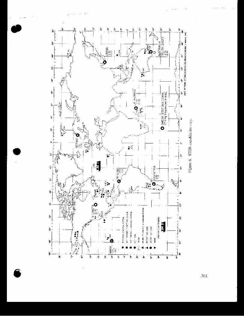
3. To test the global covcrugc of the syslern
111 ordur to test the global coverage, orlc should interconiparc the results ol' signal reception and precision obtained f'torn all tlic ciglit stations to determine if all or only selectcd OMEGA transmitting statrorms arc i~eedrd and at tlic same tiwe to detcmmine the cxtent they arc interconlrolled.
1:igurc h illustrates the geograpliic~l loc,~tions ol thc c ~ g h t OMLGA stations relativc to our tracking network. ?'his figtlrc s l~ows that most of 0111 t rack~ng ststrons arc within about 5000 miles. This d~s tancc is bl-1irvc.d to be wit l i~n thc good \~gnal reccptioii range for V1,F transmissions.
Obviously, tlic first thing that wc shall try to d o 1s to coordirlate the time transrnissioiis from the OMEGA st;ftio~is. Next we shall try to \elect thc loc,itlon\ which are the most suitable for the test, rn partrculnr, the \ i t ? \ fronm our tr,~cking stattons. Thcrc have been a
a number of people fro111 tl-ic Drpartmcnt of L)cfcnse, the National Bureau of Standards, and so on, wl-lo have participated i n this program wrth us and with whom we certainly shall coordinate the test program.
Comment bn Units for V L F Phase Recording
Wc would like to rrlake one conmmcim t in regard t o the units for phase recording; that is the units of ~nicrosecond and cyclc. 1 rccall some years ago when VLF receivcxs were designed; there was a coilsidcrable discussiun on liow the phase should bc rccordcd and in what ur~its the phase sliuuld be exprcsscd. 'I'hc dccision at the tirile was in favor of the u~ l i t of tirric arid furthcrnmorc the f~l l l scnlc of 3 pli~lse record was cl-losen to be 100 rnicro- seconds for phase-tracking VLI: rec~iver .
Whilc tlic rcasorl at the time was t l ~ t tlic f r cq i t c~~cy ol' the VLI-: triinsmissions was not rigidly controlled and sub.jec.1 to ~harlge, v l -~d also th;rt tllc full scale in timc units would be casicr for tht: operator tu record atlci to rcad, thc itnportant rcasori which remains valid today is in thc simplicity in recerver dusign and urlil'orrnity in phasc records.
This decis~nil w a s not rnCldv w ~ t h o u t cons~~l ta t inn w~t l i a ther Llserq. In rctrosl?cct, if one looks at the past phasc rccords, lie will Ilnd ii~ariy ,idvantages when Iic trie\ t o use the phase records. Had tllc p11:lsc rczurds bccrl rc~ordccl ill cycles, lle would havc to know tlic carrier frcqircrir,y of tlie Ir;ln\t-nitter In ordcr to know exactly what is tlic full scale. The disadvantage of tlus system is that the phase rccord is not con tlnuous: unlike the cyclc
recordings, the phase of a signal does not come back to the same point after a pcrturba- tion due t o sudden ionospheric disturbance.
Perhaps it is time t o re-examine the need of standardization in the selection of units for phase recordings. We really d o !lot see an easy so!ution nor a great conflict between the navigator's unit of cycles and the time user's unit of microseconds provided thc uni t is clearly stated.
Figurc 1 . The ten-second OMEGA transrnissiun sequence.