Effective September, 2005 Copyright 2005 800-621-1506 www.appletonelec.com PAGE 1 I-1 I Unions, Couplings and Seals: Explosionproof, Dust-Ignitionproof Page Description 2-4 UNY and UNF Unions; UNL Union Elbows 4 Dimensions 2,3,5 UNY and UNF Expansion Unions 5 Dimensions 2,3,7-9 EYS, EYSEF/EYDEF, EYSF/EYSM and ESUF/ESUM Sealing Fittings 10,11,15 Grayloy ® Iron and Malleable Iron Drain Sealing Fittings and Sealing Hubs 13,14 Sealing Fittings Dimensions 15 Sealing Hubs Dimensions 16 Sealing Cement and Filler 2,3,12 EYDM Drain Sealing Fittings 14 Dimensions 16 Sealing Cement and Filler 2,3,17 EXGJH/EXLK Flexible Couplings 18 Dimensions 2,3,19 PLG Close-Up Plugs and BR Reducers 2,3,20 EL 45° and 90° Elbows, and UNA Flexible Elbows 20 Dimensions 2,3,21 ECDB Combination Drain-Breather 22-24 Liquid tight Strain Relief Cord and Cable Connectors 25 Wire Mesh Strain Relief for Use with Aluminum & Steel Cord Grips 26-27 TMC, TMCX Cable Connectors 28-42 Cable Glands 28 Selection Guide 29 A2 Industrial 30 A2F Flameproof Ex d & Increased Safety 31 T3CDS 32 PXSS2K 33 Protex 2000 (PXB2KX) 34 Protex 2000 (PX2KX) 35 C2KX Marine 36-39 Adaptors and Reducers 40-41 Stopper Plugs 42 Accessories and Tools 43 Rigid Metal Conduit Fittings 43 Entrance Caps 44 Expansion Couplings and Bonding Jumpers 45 Deflection and Expansion Couplings 46 Conduit Hubs 47 Pulling Fittings 48 Reducers 49-51 Beam Clamps and Hangers 52 Cable Tray Clamps 53-62 Liquid tight Flexible Metal Conduit Connectors and Hubs (ST, STB, STN and PG Series)
Transcript
Effective September, 2005Copyright 2005
800-621-1506www.appletonelec.com
PAGE 1
I-1I
Unions, Couplings and Seals:Explosionproof, Dust-Ignitionproof
Page Description 2-4 UNY and UNF Unions; UNL Union Elbows 4 Dimensions 2,3,5 UNY and UNF Expansion Unions 5 Dimensions 2,3,7-9 EYS, EYSEF/EYDEF, EYSF/EYSM and ESUF/ESUM Sealing Fittings 10,11,15 Grayloy® Iron and Malleable Iron Drain Sealing Fittings and Sealing Hubs 13,14 Sealing Fittings Dimensions 15 Sealing Hubs Dimensions 16 Sealing Cement and Filler 2,3,12 EYDM Drain Sealing Fittings 14 Dimensions 16 Sealing Cement and Filler 2,3,17 EXGJH/EXLK Flexible Couplings 18 Dimensions 2,3,19 PLG Close-Up Plugs and BR Reducers 2,3,20 EL 45° and 90° Elbows, and UNA Flexible Elbows 20 Dimensions 2,3,21 ECDB Combination Drain-Breather 22-24 Liquid tight Strain Relief Cord and Cable Connectors 25 Wire Mesh Strain Relief for Use with Aluminum & Steel Cord Grips 26-27 TMC, TMCX Cable Connectors 28-42 Cable Glands 28 Selection Guide 29 A2 Industrial 30 A2F Flameproof Ex d & Increased Safety 31 T3CDS 32 PXSS2K 33 Protex 2000 (PXB2KX) 34 Protex 2000 (PX2KX) 35 C2KX Marine 36-39 Adaptors and Reducers 40-41 Stopper Plugs 42 Accessories and Tools 43 Rigid Metal Conduit Fittings 43 Entrance Caps 44 Expansion Couplings and Bonding Jumpers 45 Deflection and Expansion Couplings 46 Conduit Hubs 47 Pulling Fittings 48 Reducers 49-51 Beam Clamps and Hangers 52 Cable Tray Clamps 53-62 Liquid tight Flexible Metal Conduit Connectors and Hubs (ST, STB, STN and PG Series)
Effective September, 2005Copyright 2005
PAGE 2
800-621-1506www.appletonelec.com
I-2
I
Unions, Sealing Fittings, Flexible Couplings, Elbows, Drain/Breather, Close-Up Plugs: ExplosionproofUNILETS® for Use with Threaded Metal Conduit
Applications: Unions• UNY and UNF unions are used for joining conduit and connecting conduit to enclosures. Facilitates modifications, permits removal of enclosures without turning or removal of conduit.
• Expansion unions compensate for expansion and contraction of conduit.
Applications: Sealing Fittings• Prevent passage of gases, vapors or flames from one portion of conduit system to another. Restrict any ex-plosion to the sealed off enclosure. Prevent pressure piling within conduit system.
• Required in Class 1, Division 1 and 2 locations within 18” of enclosures containing apparatus that may cause arcs, sparks or high temperatures.
• Required in Class I, Division 1 and 2 locations where 2” or larger conduit enters enclosure, fitting housing termi-nals, splices or taps.
• Required in Class 1, Division 1 and 2 locations at the boundary where conduit leaves classified location.
• Required in Class 1, Division 1 and 2 locations where two or more enclo-sures are connected by 36” or less conduit. Seal must be located within 18” of either enclosure.
• Required where cables (which exceed rate of gas or vapor transmis-sion permitted for seals) are used in Class 1, Division 2 locations.
Applications: Sealing Hubs• Used to seal vertical conduit risers at switch gear and motor control centers, sheet metal structures, or cast boxes and enclosures.
Applications: Flexible Couplings• Used in areas where vibration and/or movement is a problem. Also used in place of rigid conduit in difficult-bend situations.
Applications: Combination Drain/Breather• ECBD, when installed in bottom of hous-ing, functions as a drain for water formed by condensation within system. Installed in top of housing, it serves as a breather, providing ventilation to minimize conden-sation and prevent mildew formation.
ECDB Drain/Breathers
➌ EY, EYS, EYD Series Drain Seals
➍ ES Series Sealing Hubs
➊ UNY/UNF Unions ➋ UNY/UNF Expansions Unions
➎ EXGJH/EXLK Flexible Couplings
EL Elbows
BR Bell ReducerPLG Close-Up Plugs
Effective September, 2005Copyright 2005
800-621-1506www.appletonelec.com
PAGE 3
I-3I
Unions, Sealing Fittings, Flexible Couplings, Elbows, Drain/Breather, Close-Up Plugs: ExplosionproofUNILETS® for Use with Threaded Metal Conduit
Features: All Fittings• Explosionproof, dust-ignitionproof.
• Smooth, rounded integral bushing in each hub protects conductor insulation.
• Accurately tapped, tapered threads for tight, rigid joints and ground continuity.
Features: Non-Expansion Unions❶ Concentric ring interlocked design of 1/2”, 3/4” and 1” sizes makes possible smaller diameter, allowing use in tight-er spaces. 1-1/4” and larger UNY sizes have removable male nipple.
• Choice of malleable iron or alumi-num.
Features: Expansion Unions❷ One-piece design eliminates need for disassembly during installation.
• Telescoping cylinder within cylinder design permits expansion or contraction.
• Standard or long types available.
• Small external diameters—excellent in restricted areas in wiring of pumps, motors, and other equipment.
• Internal phosphor bronze “bonding jumper” ring assures positive ground between telescoping cylinders.
• Removable nipple in male sealing fitting may be used interchangeably in top or bottom hub.
• EYS—for sealing vertical conduit. Large opening for damming and filling.
• Expanded Fill EYSEF/EYDEF— allow up to 40% conduit fill in compliance with the National Electrical Code.
• EYSF/EYSM—for sealing vertical con-duit. Large opening for damming and fill-ing.
• ESUF/ESUM for sealing vertical or horizontal conduit. Pouring spout rotates 90° Removable cover provides full access for damming 2-1/2” thru 4” sizes have threaded cover openings for damming.
• EYF/EYM—close radius type for seal-ing vertical or horizontal conduit runs.
• EYDM Drain Sealing Fittings—close radius type for sealing vertical conduit runs. Access cover has drain valve for automatic draining of water accumula-tion above the seal.
• Kwiko® A sealing cement is a specially formulated water soluble powder. Mixed to the proper proportions, it is poured in sealing fittings and hardens to contain
and restrict the passage of gases and explosions in classified areas.
• Fiber Filler-makes dams around and between all conductors to prevent sealing compound from leaking while being poured in its liquid state.
Features: Sealing Hubs❹ UL Listed for use in hazardous locations when Kwiko® A Sealing Compound or Crouse-Hinds Chico® A Sealing Compound are used to make the seal.
Features: Flexible Couplings❺ Heavy duty design resists mechani-cal abuse. Watertight.
• Electrical conductivity equal to rigid conduit on a similar length basis—no bonding jumper required.
• Interior insulating liner protects con-ductors from abrasion under vibrating conditions.
• EXGJH—both end fittings are female, each furnished with a removable male nipple.
• EXLK—female end fitting with union at one end and a female end fitting with a removable male nipple at the other end.
Standard Materials• UNY and UNF (Non-Expansion) Unions, 1/2” thru 1”: steel or aluminum. 1-1/4” thru 6”: malleable iron or aluminum.
• UNY and UNF Expansion Unions: steel.
• UNL Unions: malleable iron and steel.
• EYSF/EYSM, EYF/EYM and EYDM Seals: malleable iron or Almag 35 aluminum.
• EYS, EYSEF/EYDEF, and ESUF/ESUM: malleable iron.
• EYD and EYS Seals: Grayloy®-iron.
• EXGJH and EXLK Couplings, 1/2” thru 2”: outer bronze braid, inner brass core with insulating liner; 2-1/2” thru 4”: outer stainless steel braid, inner stainless steel core with insulating liner. End Fittings: 1/2” thru 2”—brass; 2-1/2” thru 4”—stainless steel.
• PLG Close-Up Plugs: malleable iron, steel, or aluminum.
Standard Finishes• Unions—UNY,UNF and UNL (Non-Ex-pansion) and UNY and UNF (Expansion)
of malleable iron have triplecoat—(1) zinc electroplate, (2) dichromate, and (3) epoxy powder coat, of steel have zinc electroplate, of aluminum 1/2” thru 2” have natural finish and 2-1/2” thru 4” have epoxy powder coat.
• Sealing Fittings— EYSF/EYSM, ESUF/ESUM, EYF/EYM,EYDM and EYD/EYS of malleable iron and Grayloy®-iron have triple-coat—(1) zinc electroplate, (2) dichromate, and (3) epoxy powder coat, of Almag 35 aluminum have epoxy powder coat.
• Sealing Hubs—ES of malleable iron have a triple-coat—(1) zinc electroplate, (2) dichromate, and (3) epoxy powder coat.
• Flexible Couplings—EXGJH and EXLK natural finish.
• Close-up Plugs—PLG of malleable iron have a triple-coat—(1) zinc electroplate, (2) dichromate, and (3) epoxy powder coat; steel have zinc electroplate; alumi-num have natural finish.
• Bell Reducers—BR of malleable iron have a triple-coat—(1) zinc electroplate, (2) dichromate, and (3) epoxy powder coat; aluminum have natural finish.
• Elbows—EL are malleable iron and have zinc electroplate; UNA are mal-leable iron and have a triple-coat—(1) zinc electroplate, (2) dichromate, and (3) epoxy powder coat.
• Combination Drain/Breathers—ECDB are passivated stainless steel and have a natural finish.
Options• For ES Sealing Hubs, add suffix BLSG for sealing gaskets and locknuts (pro-vide a water and oil-tight connection).
Compliances• UL Standard 886
• Appleton malleable iron products conform to ASTM A47-77, Grade 32510. which has the following proper-ties: tensile strength, 50,000 psi; yield, 32,000 psi; and elongation, 10%.
• Appleton a luminum products are produced from a high strength copper-free (4/10 or 1% max.) alloy.
• Class I, Div. 1 & 2 and Class II, Div. 1 & 2, if installed as follows: Unions, Elbows, Plugs, Flex. Couplings—NEC 501-4 (a)(b); Seals—NEC 501-5 (a)(b)(c)(d)(e) and NEC 502-5; Drains—NEC 501-5(f).
Effective September, 2005Copyright 2005
PAGE 4
800-621-1506www.appletonelec.com
I-4
I
Unions: UNY, UNF, and UNL;Explosionproof, Dust-IgnitionproofUNILETS® for use with Threaded Metal Conduit
Class I, Div. 1 and 2Groups A‡,B◆,C,DClass II, Div. 1 and 2Groups E,F,GClass III
Catalog Number Dimen. in Dimen. in Size Inches Millimeters Steel (1/2” to 1”) and Aluminum (Inches) A B A B Malleable (1-1/4” to 6”) (1/2” to 4”)
UNL 90° Elbow Unions For connecting conduit to enclosure
Male-Female A B C A B C 1/2-1/2 2.44 1.38 1.75 62.0 35.1 44.5 UNL50N‡
1/2-3/4† 2.46 1.63 1.69 62.5 41.4 42.9 UNL50-75N‡
3/4-1/2† 1.94 1.38 1.50 49.3 35.1 38.1 UNL75-50N‡
3/4-3/4 2.03 1.63 1.56 51.6 41.4 39.6 UNL75N‡
‡ Indicates items in the shaded area which are U.L. Listed for Class I, Groups A,B,C & D; Class II, Groups E,F and G; and Class III.◆ Indicated items in the shaded area which are U.L. Listed for Class I, Groups B,C and D; Class II, Groups E,F and G; and Class III.† Male end given first.
Effective September, 2005Copyright 2005
800-621-1506www.appletonelec.com
PAGE 5
I-5I
Expansion Unions: UNY and UNF;Explosionproof, Dust-IgnitionproofUNILETS® for Use with Threaded Metal Conduit
Class I, Div. 1 and 2Groups C,DClass II, Div. 1 and 2 Groups E,F,GClass III
Catalog Number Size (Inches) Steel
UNY Male Unions— Standard For connecting conduit to enclosure 1/2 UNY50 3/4 UNY75 1 UNY100 UNYL Male Unions— Long For connecting conduit to enclosure 1/2 UNYL50 3/4 UNYL75 1 UNYL100
UNF Female Unions— Standard For connecting conduit to conduit 1/2 UNF50 3/4 UNF75 1 UNF100 UNFL Female Unions— Long For connecting conduit to conduit 1/2 UNFL50 3/4 UNFL75 1 UNFL100
Dimensions in Inches
A B C DCatalog Size (Overall Length at (MaximumNumber (Inches) Max. Expansion) Expansion)
NEC Sec. 501-5 Highlights on Sealing Fitting RequirementsClass I, Div. 1 and 2.
Sealing fittings prevent passage of gases, vapors or flames from one por-tion of a conduit system to another. They also restrict large amounts of ig-nitable gases or vapors from accumu-lating to confine explosive pressure.
Appleton sealing fittings are suitable for Class I and II locations.EYS, SF and EYD are for sealing verti-cal conduit. EY and ESU are for seal-ing vertical and horizontal conduit. SF and EYD also have drain valves.
Class I, Div. 1 and 2Seals must be placed in each conduit within 18” of a device that may produce arcs, sparks, or high temperatures.
Sec. 501-5(a)(1) permits explosion-proof unions, couplings, elbows, and Appleton ER Conduit Outlet Bodies between seal and appara-tus enclosure.
Class I, Div. 1 and 2Where 2” or larger conduit enters enclo-sure, fitting housing terminals, splices or taps, seals are required within 18” or such enclosure.
2” or larger conduit
Class I, Div. 1 and 2Sealing fittings must be installed at boundary between a hazardous and non-hazardous area.** Sealing fitting must also be installed at boundary between a Class I, Div. 1 area and a Class I, Div. 2 area.
Enclosure to be sealed
IMPORTANT NOTE: Where 2” or larger conduit is used with an enclosure required to be approved for Class I, Div. 1, or at a boundary where any size conduit leaves a hazardous area to a non-hazardous area (or from Div. 1 to Div. 2), external seals must ALWAYS be used. However, external seals need not be placed within 18” of an enclosure containing an arcing device if the product is factory sealed for the specific Class and Group.
Other NEC Requirements• Splices and taps are not to be used in sealing fittings.• Where moisture may accumulate in system, an ap-proved method must be provided to remove suchaccumulation.• Depth of sealing compound should be equal to trade size of conduit, having a minimum thickness of 5/8”.
Sealing Compound
Seal may be positionedon either side of boundary
Effective September, 2005Copyright 2005
800-621-1506www.appletonelec.com
PAGE 7
I-7I
Sealing Fittings: EYS and ESU;Explosionproof, Dust-Ignitionproof, RaintightUNILETS® for use with Threaded Metal Conduit
Class I, Div. 1 and 2 Groups A,B◆,C,DClass II, Div. 1 and 2 Groups E,F,GClass III
Kwiko® A Catalog Number Size Turning Radius† Cement Req’d Almag 35* (Inches) Inches (cm) Ozs. (Grams) Malleable Iron* Aluminum
‡ Per Nec 501-5(c)(6) seals in Class I, Division 1 and 2 must be limited to conductor fill of 25% of cross sectional area of a rigid metal conduit of the same trade size unless approved for higher percentage fill. See 40% fill seals on page I-9. ◆ Indicated items in the shaded area which are suitable for Class I, Groups A,B,C and D; Class II, Groups E,F,G; and Class III.* U.L. Listed for use with Appleton “Kwiko® A” and Crouse-Hinds “Chico® A” cement.† Turning radius with cover or plug removed.
1/2”—1”
1/2”—1”
1/2”—1”
Effective September, 2005Copyright 2005
PAGE 8
800-621-1506www.appletonelec.com
I-8
I
Sealing Fittings for Close Turning Radius: EY; Explosionproof, Dust-Ignitionproof, RaintightUNILETS® for use with Threaded Metal Conduit
Class I, Div. 1 and 2Groups A‡,B,C,DClass II, Div. 1 and 2Groups E,F,GClass III
Kwiko® A Catalog Number Size Turning Radius† Cement Req’d Malleable Almag 35 Inches Inches (cm) Ozs. (Grams) Iron* Aluminum*
EY Vertical and Horizontal Conduit Seals for Close Turning Radius (25% fill)**
** Per Nec 501(c)(6), seals in Class I, Division 1 and 2 must be limited to conductor fill of 25% of cross sectional area of a rigid metal conduit of the same trade size unless approved for higher percentage fill. See 40% fill seals on page I-9.Shaded area indicates items which are U.L. Listed for Class I, Groups B,C, and D; Class II, Groups E,F and G; and Class III.‡ Indicates items which are U.L. Listed for Class I, Groups A,B,C, and D; Class II, Groups E,F and G; and Class III.* U.L. Listed for use with Appleton “Kwiko® A” and Crouse-Hinds “Chico® A” cement.† Turning radius with cover or plug removed.‡ Not U.L. Listed. CSA Certified only.
Effective September, 2005Copyright 2005
800-621-1506www.appletonelec.com
PAGE 9
I-9I
Sealing Fittings for Close Turning Radius and 40% Fill: EY; Explosionproof, Dust-Ignitionproof, RaintightUNILETS® for use with Threaded Metal Conduit
Class I, Div. 1 and 2Groups A‡,B,C,DClass II, Div. 1 and 2Groups E,F,GClass III
Kwiko® A Catalog Number Size Turning Radius† Cement Req’d Malleable Almag 35 (Inches) Inches (cm) Ozs. (Grams) Iron* Aluminum*
EXPANDED FILL EYSEF and EYDEF (40% fill) EYSEF 1/2”-4” Vertical and Horizontal Conduit Seals for Close Turning Radius Female 1/2 1.25 (3.18) 2 (56.8) EYSEF50‡ EYSEF50AL‡
Shaded area indicates items which are U.L. Listed for Class I, Groups B,C, and D; Class II, Groups E,F and G; and Class III.‡ Indicates items which are U.L. Listed for Class I, Groups A,B,C, and D; Class II, Groups E,F and G; and Class III.* U.L. Listed for use with Appleton “Kwiko® A” and Crouse-Hinds “Chico® A” cement.† Turning radius with cover or plug removed.
1/2” - 3/4” 1” - 2-1/2” 3” - 4”
1/2” - 3/4” 1” - 2-1/2” 3” - 4”
Effective September, 2005Copyright 2005
PAGE 10
800-621-1506www.appletonelec.com
I-10
I
EYS Grayloy™-Iron Sealing Fittings:Explosionproof, Dust-Ignitionproof, RaintightUNILETS® for use with Threaded Metal Conduit
Class I, Div. 1 and 2Groups A‡,B,C,DClass II, Div. 1 and 2Groups E,F,GClass III
‡ Shaded area indicates items which are U.L. Listed for Class I, Groups A,B,C, and D; Class II, Groups E,F and G; and Class III.* U.L. Listed for use with Appleton “Kwiko® A” and Crouse-Hinds “Chico® A” cement.† Turning radius with cover or plug removed.** Per Nec 501(c)(6), seals in Class I, Division 1 and 2 must be limited to conductor fill of 25% of cross sectional area of a rigid metal conduit of the same trade size unless approved for higher percentage fill. See 40% fill seals on page I-9.
Female Male
Female
Male
Female/Male EYS
Kwiko® A Size Turning Radius† Cement Req’d Catalog Number (Inches) Inches (cm) Ozs. (Grams) Grayloy™-Iron*
EYS Vertical and Horizontal Conduit Seals (25% fill)** for Close Turning Radius
‡ Per Nec 501-5(c)(6) seals in Class I, Division 1 and 2 must be limited to conductor fill of 25% of cross sectional area of a rigid metal conduit of the same trade size unless approved for higher percentage fill. See 40% fill seals on page I-9. * U.L. Listed for use with Appleton “Kwiko® A” and Crouse-Hinds “Chico® A” cement.† Turning radius with cover or plug removed.
Effective September, 2005Copyright 2005
PAGE 12
800-621-1506www.appletonelec.com
I-12
I
Drain Sealing Fittings: EYD;Explosionproof, Dust-Ignitionproof, RaintightUNILETS® for Use with Threaded Metal Conduit
Class I, Div. 1 and 2Groups B,C,DClass II, Div. 1 and 2Groups E,F,GClass III
Kwiko® A Catalog Number Size Turning Radius◆ Cement Req’d Malleable Almag 35 (Inches) Inches (cm) Ozs. (Grams) Iron† Aluminum†
EYDM Vertical Conduit Drain Seals for Close Turning Radius (25% fill)‡
‡ Per Nec 501-5(c)(6) seals in Class I, Division 1 and 2 must be limited to conductor fill of 25% of cross sectional area of a rigid metal conduit of the same trade size unless approved for higher percentage fill. See 40% fill seals on page I-9. Shaded area indicates items which are UL Listed for Class I, Groups B,C and D; Class II, Groups E,F and G; and Class III.
† U.L. Listed for use with Appleton “Kwiko® A” and Crouse-Hinds “Chico® A” cement.◆ Turning radius with cover or plug removed.
Effective September, 2005Copyright 2005
800-621-1506www.appletonelec.com
PAGE 13
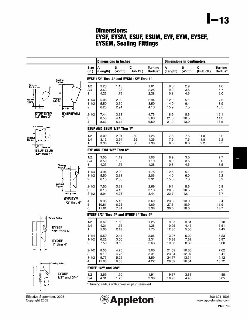
I-13I
Dimensions in Inches Dimensions in Centimeters
Size A B C Turning A B C Turning (In.) (Length) (Width) (Hub CL) Radius* (Length) (Width) (Hub CL) Radius*
Size A B Turning A B Turning (In.) (Length) (Width) Radius* (Length) (Width) Radius* EYS, Vertical and Horizontal Sealing, Close Turning Radius 1/2” Thru 6”
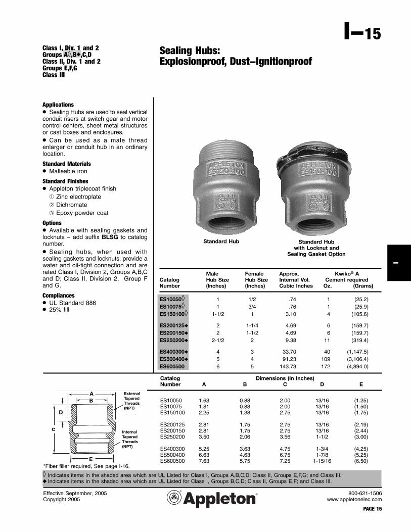
Class I, Div. 1 and 2Groups A◊,B◆,C,DClass II, Div. 1 and 2Groups E,F,GClass III
Applications• Sealing Hubs are used to seal vertical conduit risers at switch gear and motor control centers, sheet metal structures or cast boxes and enclosures.
• Can be used as a male threadenlarger or conduit hub in an ordinary location.
Options• Available with sealing gaskets and locknuts − add suffix BLSG to catalog number.
• Sealing hubs, when used with sealing gaskets and locknuts, provide a water and oil-tight connection and are rated Class I, Division 2, Groups A,B,C and D; Class II, Division 2, Group F and G.
Compliances• UL Standard 886• 25% fill
Male Female Approx. Kwiko® ACatalog Hub Size Hub Size Internal Vol. Cement required Number (Inches) (Inches) Cubic Inches Oz. (Grams)
◊ Indicates items in the shaded area which are UL Listed for Class I, Groups A,B,C,D; Class II, Groups E,F,G; and Class III.◆ Indicates items in the shaded area which are UL Listed for Class I, Groups B,C,D; Class II, Groups E,F; and Class III.
Kwiko® A TwinPak® Sealing CementsEach plastic pouch contains: Pre-measured Kwiko® A cement and Pre-measured water (in an inner bag).Squeeze pouch to break inner water bag and knead mixture thoroughly, then pour. Kwiko® A TwinPak® also includes adequate amount of fiber filler packed separately.
1/2” and 3/4” Sizes:Suitable for Class I, Groups A,B,C and D; Class II, Groups E,F and G, and Class III.Custom lengths available—consult factory.
1” Size:Suitable for Class I, Groups C and D; Class II, Groups E,F and G, and Class III.
1-1/4” thru 4” Sizes:Suitable for Class I, Group D; Class II, Groups E, F and G, and Class III.
Flexible Couplings: EXGJH and EXLK;Explosionproof, Dust-Ignitionproof, WatertightUNILETS® for use with Threaded Metal Conduit
Class I, Div. 1 and 2Groups A,B,C,DClass II, Div. 1 and 2Groups E,F,GClass III
Shaded area (1/2” and 3/4” sizes) indicates items suitable for Class I, Groups A and B as well as Class I, Groups C,D; Class II, Groups E,F,G; and Class III.
1/2” thru 2” brass alloy is standard.1/2” thru 2” available in stainless steel. Add suffix —SS.2-1/2” thru 4” stainless steel is standard.1/2” thru 1” stainless steel nipple. Add suffix —NS.NOTE: Unions are not available in stainless steel.
◊ Indicates items in the shaded area which are UL Listed for Class I, Groups A,B,C and D; Class II, Groups E,F and G; and Class III.◆ Indicates items in the shaded area which are UL Listed for Class I, Groups B,C and D; Class II, Groups E,F and G; and Class III.
Effective September, 2005Copyright 2005
PAGE 20
800-621-1506www.appletonelec.com
I-20
I
45° and 90° Elbows:Explosionproof, Dust-IgnitionproofUNILETS® for use with Threaded Metal Conduit.
Class I, Div. 1 and 2Groups A,B,C,DClass II, Div. 1 and 2Groups E,F,GClass III
Size Dimensions (A) Catalog Number NPT Threads Inches Inches (mm) Malleable Iron Aluminum
Shaded area indicates items suitable for Class I, Groups A and B in addition to Class I, Groups C,D; Class II, Groups E,F,G; and Class III.
800-621-1506www.appletonelec.com
PAGE 21
I-21I
Drain, Breather, Universal Drain and Breather:Explosionproof, Dust-Ignitionproof, Thread/Joint Lubricants
Class I, Div. 1 and 2Groups B,C,DClass II, Div. 1 and 2Groups E,F,GClass III
Effective and stable at temperatures from-100°F to 750°F (-38°C to +399°C). Homo-geneous metallic powder in a hydrocarbon agent. Supports ground continuity.
Effective and stable at temperatures from 0°F to 250°F (18°C to 121°C). Petroleum based lubricant.
Shaded area indicates items suitable for Class I, Group B, Groups C and D; Class II, Groups E, F and G; and Class III.
ECDB38
ECDB50HP
TLNC—Non Conductive 4 oz. TLNC-4
TLC—Conductive, High-Temperature 3 oz. TLC-3
DRAIN FITTINGS:Generally installed at bottom of enclosure housing to drain moisture caused by condensa-tion.
BREATHER FITTINGS:Generally installed at top of enclosure housing to minimize condensation.
UNIVERSAL DRAIN-BREATHER FITTINGS:Generally installed at top and/or bottom of enclosure housing. The features of a drain fitting and a breather fitting are combined into one fitting.
Thread/joint lubricants prevent seizing and galling and reduce wear and breakage of mating parts. These lubricants have excellent qualities that inhibit corrosion and retard galvanic action on dissimilar metals.
Type - Thread/Joint Lubricants Size✝ Catalog Number
*Also suitable for Class I, Div. 2 per NEC 501.10(B).
CRN50
BRTB4X
ECDB50B
Type Size Catalog Number
NEMA 3R Universal Drain and BreatherFor high performance water drainage and continuous ventilation. Stainless Steel.
1/2” ECDB50HP
NEMA 4X BreatherFor continuous ventilation. Stainless Steel. 1/2” BRTB4X
NEMA 4X DrainFor automatic water drainage. Stainless Steel. 1/2” ECD50B4X
Group B Universal Drain and BreatherRaintight. For automatic water drainage and continuous ventilation. Stainless Steel.
3/8” ECDB38B1/2” ECDB50B
Groups C & D Universal Drain and BreatherFor automatic water drainage and continuous ventilation. Stainless Steel.
3/8” ECDB38
Non-Hazardous Location Drain*Aluminum. For steel add suffi x - S. 3/8” CRN38
1/2” CRN503/4” CRN75
Effective July, 2007Copyright 2007
ECD50B4X
Effective September, 2005Copyright 2005
PAGE 22
800-621-1506www.appletonelec.com
I-22
I
Liquidtight Strain Relief Cord and Cable Connectors and Wire Mesh Strain ReliefAluminum and Steel, for use with Flexible Power or Control Cable.
ApplicationsAluminum and Steel CG Series:
• Provide a liquidtight and strain relief termination for flexible type neoprene, hypalon and PVC jacketed power or control cord and cable.
• For use in wet or dry locations seal-ing electrical connections against dust and dirt, oil, water or other atmosphere containing moisture.Wire Mesh Strain Relief:
• For use with cord and cable subjected to flexure, vibration, motion, or strain. Cap on standard CG Series cable connector is replaced with cap with woven wire mesh strain relief.
FeaturesAluminum and Steel CG Series:
• Available in straight or 90° type, alu-minum or steel construction to meet the requirements of rugged service on all types of equipment.
• Identification label clearly states the catalog number and minimum-maxi-mum cable diameter range for which the connector is designed.
• Elastomeric sealing gland firmly and safely grips cable jacket, provid-ing strain relief and protecting internal wiring connections against external tension on cable or cord.
• Steel or Teflon* washer reduces friction between gland and connector cap; provides even pressure distribu-tion and eliminates leakage resulting from gland distortion.
• Large aluminum connectors 1-1/2” thru 4” and all steel connectors are constructed with hex head cap.Wire Mesh Strain Relief:
• Stainless steel wire mesh prevents pull-out of cord and cable.
• Wire mesh strain reliefs for use with aluminum cord grips have knurled cap.
• Wire mesh strain reliefs for use with steel cord grips have hex cap.
Standard Materials• CG Aluminum connectors consist of aluminum body and cap of copper-free aluminum (4/10 of 1% copper or less). Sealing gland is an elastomer, and washer is steel or Teflon*, 90°
connectors have cast aluminum body.
• CG Steel connectors sizes 1/4 thru 2” have machined steel body and cap. Sealing gland is and elastomer and washer is steel or Teflon.*Wire Mesh Strain Relief:
• Copper free aluminum (4/10 or 1% copper or less) cap with stainless steel wire mesh strain relief.
• Machined steel cap with zinc electroplate finish and stainless steel wire mesh strain relief.
SizesAluminum and Steel CG Series
• CG Series in aluminum construction is available in straight type from 1/4” thru 4”, 90° type from 3/8” thru 1-1/4”.
• CG Series in steel construction is available in straight type from 1/4” thru 2” and 90° type from 3/8” thru 1-1/4”.Wire Mesh Strain Relief:
• 3/8” thru 1-1/4”.
Compliances• UL Listed, File No. E14817.
• Suitable for classified location use in Class I, Div. 2 areas. See listing page for detailed hazardous area usage information.
• NEMA 3R (Rain tight)* Teflon is a registered trademark of E.I. DuPont de Nemours & Co.
Effective September, 2005Copyright 2005
800-621-1506www.appletonelec.com
PAGE 23
I-23I
Liquidtight Strain Relief Cord and Cable Connectors: StraightFor use in Wet or Dry Locations
Class I, Div. 2Class II, Div. 1 and 2Class IIINEC 501-4(b), 502-4(a)(2),503-3(a)
Straight Connectors Catalog Numbers Cable Range Dimensions (In.)
If locknuts are required, use BL type locknuts: Catalog Section CF* Remove sufficient outer covering of cord or cable to pass conductors through connector body.
For replacement glands for CG and CG90 connectors, see Catalog Section CC, Page 5.
For 90° Connectors see page I-24
Effective September, 2005Copyright 2005
PAGE 24
800-621-1506www.appletonelec.com
I-24
I
90° Connectors Catalog Numbers Cable Range Dimensions (In.)Aluminum Steel (Inches) A B
Liquidtight Strain Relief Cord and Cable Connectors: 90°For use in Wet or Dry Locations
Class I, Div. 2Class II, Div. 1 and 2Class IIINEC 501-4(b), 502-4(a)(2),503-3(a)
If locknuts are required, use BL type locknuts: Section CF* Remove sufficient outer covering of cord or cable to pass conductors through connector body.
For replacement glands for CG and CG90 connectors, see Catalog Section CC, Page 5.
Effective September, 2005Copyright 2005
800-621-1506www.appletonelec.com
PAGE 25
I-25I
Wire Mesh Strain Relief for Use with Aluminumand Steel Cord Connectors
For Aluminum Cord Connectors Use For Steel Cord Connectors Use Dimensions (Inches)CG-Straight CG-90 Catalog Number CG-Straight CG-90 Catalog Number A B
For Connectors with 3/8 Inch Hubs For Connectors with 3/8 Inch Hubs
Applications• TMC connectors are designed for use with the following cables: MC/MCHL – Corrugated Interlocked Aluminium/Steel Armor and Continuously Welded Armor Cables, e.g. TECK or CLX.
• TMC connectors provide a means for terminating jacketed type MC cable, forming a mechanical watertight con-nection and providing ground continuity for cable armor.
• For Class I hazardous locations – See TMCX.
• Watertight-NEMA Type 4.Features
• Integral ‘O’ ring face seal providing – 4X & IP66
• Independent sealing and armor clamping
• True 360º grounding
• Superior pull out prevention
• Compact slim profi le
• Reduced installation time (no disas-sembly required)
• Widest Cable acceptance Range
• Re-usable design• Additional Integral Deluge proof seal
for protection in extreme offshore and onshore environments
• Metric option available
Standard Materials• Bodies, Sleeve and gland nut are copper-free aluminum, nickel plated brass, stainless steel.
( 1) Where explosion proof enclosures are being used the TMC must be installed in conjunction with an approved pouring or compound sealing fi tting. In Division 2 areas the TMC can be fi tted directly to an enclosure which has no source of ignition in accordance with NEC/CEC requirements.
* Stainless Steel is priced by quote only. Contact your factory representative for assistance.
800-621-1506www.appletonelec.com
PAGE 27
I-27I
Effective September, 2008Copyright 2008
Class I, Div. 1 and 2, Groups A,B,C,DClass I, Zone 1, AExd IICClass II, Div. 1 and 2 Groups E,F,GClass IIINEMA 4X, IP66
TMCX Connectors For Jacketed and Non-Jacketed Metal Clad Cable: Explosionproof, Dust-IgnitionproofTMCX For Hazardous Locations
Applications• TMCX connectors are designed for use with the following cables: MC/MCHL – Corrugated/ Interlocked Aluminium/Steel Armor and Continuously Welded Armor Cables, e.g. TECK or CLX
• TMCX connectors provide a means for terminating jacketed type MC cable, forming a mechanical watertight con-nection and providing ground continuity for cable armor.
• For use on horizontal or vertical runs.
• For use in Class I, Div. 1 & 2 and Class II, Div. 1 & 2 hazardous locations.
• For non-hazardous locations – Use TMC.Features
• Independent sealing and armor clamping
• True 360º grounding• Superior pull out prevention • Compact slim profi le• Reduced installation time• Widest cable acceptance range• Supplied complete with epoxy sealing
compound• Disconnectable design• Additional Integral Deluge proof seal for protection in extreme offshore and onshore environments
Standard Materials• Bodies, Sleeve and gland nut are copper-free aluminum, nickel plated brass, stainless steel.
* Stainless Steel is priced by quote only. Contact your factory representative for assistance.
800-621-1506www.appletonelec.com
I-28
I
Effective September, 2008Copyright 2008
PAGE 28
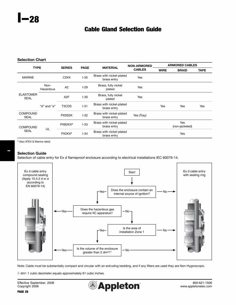
Selection Chart
TYPE SERIES PAGE MATERIALNON-ARMORED
CABLESARMORED CABLES
WIRE BRAID TAPE
MARINE C2KX I-35Brass with nickel-plated
brass entryYes
ELASTOMER SEAL
Non-Hazardous
A2 I-29Brass, fully nickel
platedYes
“d” and “e”
A2F I-30Brass, fully nickel
platedYes
T3CDS I-31Brass with nickel-plated
brass entryYes Yes Yes
COMPOUND SEAL
PXSS2K I-32Brass with nickel-plated
brass entryYes (Tray)
COMPOUND SEAL
UL
PXB2KX* I-33Brass with nickel-plated
brass entryYes
(non-jacketed)
PX2KX* I-34Brass with nickel-plated
brass entryYes
* Also ATEX & Marine rated.
Start
Does the enclosure contain aninternal source of ignition?
Does the hazardous gasrequire IIC apparatus?
Is the area ofinstallation Zone 1
Is the volume of the enclosuregreater than 2 dm3?
Selection GuideSelection of cable entry for Ex d fl ameproof enclosure according to electrical installations IEC 60079-14.
Note: Cable must be substantially compact and circular with an extruding bedding, and if any fi lters are used they are Non-Hygroscopic.
dm3: 1 cubic decimeter equals approximately 61 cubic inches.
Ex d cable entry with sealing ring
Ex d cable entry compound sealing
(Apply 10.4.2 d or e according to
EN 60079-14)
Yes
Yes
Yes
Yes No
No
No
No
Cable Gland Selection Guide
Effective September, 2008Copyright 2008
800-621-1506www.appletonelec.com
PAGE 29
I-29I
A2 Industrial Cable GlandUnarmored Cable
Applications• A2 type brass indoor and outdoor cable gland for use with all types of unarmored cable providing mechanical cable retention and an environmental seal on the cable outer sheath.Features• Designed and tested to BS 6121: Part 1: 1989, meets and surpasses the requirements of EN 50262:1999.• Brass grade CuZn39Pb3 (CW614N) to EN12168.• Continuous operating temperature range: -60°C to +150°C.Materials:• Gland: Brass, fully nickel plated
• Seal: Solo LSF• Cable type: Unarmored. Sealing technique - Displacement seal concept. Sealing area(s) - outer sheath.
Optional Accessories:• Shroud, locknut, earth tag, entry thread seal, serrated washers (I-38). Adaptors and reducers (I-35 thru I-37).• Also avail able in Brass with Nickel Plated finish, Stainless Steel & Aluminum.• Brass with nickel plated brass entry replace RA5 with RA7.• Aluminum replace RA5 with RA1.
• 316 Stainless steel replace RA5 with RA4.Compliances/Approvals:
A2F Flameproof Ex d* & IncreasedSafety Ex e Cable GlandUnarmored Cable
Applications• For use in Zone I, Zone 2, Zone 21 and Zone 22 hazardous area locations.Features• Dual Certified flameproof (Type ‘d’) and Increased Safety (Type ‘e’) indoor and outdoor cable glands.• Continuous operating temperature range: -60°C to +130°C.Materials:• Gland: Brass, fully nickel plated
• Seal: Solo LSF• Cable type: Unarmored. Sealing technique - Displacement seal concept. Sealing area(s) - outer sheath.Optional Accessories:• Shroud, locknut, earth tag, entry thread seal, serrated washers (I-38). Adaptors and reducers (I-35 thru I-37).• Integral Entry Thread Seal option available (for this option pre-fix gland type with ‘R’, e.g. 25RA2F). Also avail-able in Brass with Nickel Plated finish, Stainless Steel & Aluminum.• Brass full nickel plate add suffix -5.• Brass nickel plated entry only, add suffix -7.
• Code of protect ion category - ATEX II 2 GD Ex d* I IC & Ex e II, Ex nR II, Ex tD A621, Equipment Zone I & 2, Zone 21 & 22 - Gas Groups IIA, IIB & IIC, ATEX IM2, Ex d I, Ex e I.
• Compliance Standards - EN 60079-0:2004, EN 60079-1:2004, EN 60079-7:2003, EN 60079-15:2003, E N 6 1 2 4 1 - 0 : 2 0 0 4 E N 6 1 2 4 1 -1:2004
* The A2F Cable Gland is suitable for use with all forms of equipment protection permitted in Zone 1, Zone 2, Zone 21 and Zone 22 provided always that the prevailing code of practice for selection and installation is observed, e.g. IEC 60079-14. See page 28.
Ordering Information
Gable Gland Size
Available Entry Threads “C” Maximum
Thread Length
“E”
Overall Cable Diameter “A”
Across Flats “D”
Across Corners
“D”
Nominal Protrusion
Length “F”
NPT Catalog Number
Metric Catalog Number
PVC Shroud Reference
Cable Gland Weight (Ozs)Standard Option
NPT NPT Metric Min Max Max Max20S/16 1/2” 3/4” M20 0.591 0.126 0.343 0.945 1.047 0.827 20S16A2F1RA531 20S16A2F1RA5 PVC04 1.90
Applications• For use in Zone I, Zone 2, Zone 21 and Zone 22 – hazardous area lo-cations.Features• TRITON CDS (Compensating Displace-ment seal) T3CDS Flameproof Ex d and Increased Safety Ex e brass cable gland for all types of armored & braided cable including lead sheathed versions, provides a Flameproof seal on the cable inner sheath and an en-vironmental seal on the cable outer sheath.Inner flameproof seal:− Unique new CDS system, compat-
ible with all types of cable (eliminates cable damage and cold flow)− At the critical cable sealing point
the CDS system protects the cable inner sheath f rom any excess force, which is transferred to and absorbed by the internal compen-sator incorporated in the CDS sys-tem− A l lows the Cable Gland to be
tightened face to face every time re-gardless of cable diameter.
• Equipped with a unique Reversible
Armor Cone and Bi-Directional ArmorClamping Ring which can accommo-date SWA, braided and STA cables.• The Cable Gland provides mechani-cal cable retention, and electrical continuity via armor termination.
• Continuous operating tempera-ture range of -60°C to +130°C.Materials:• Standard Cable Gland: Brass with Nickel-Plated threaded entry• Seal: Solo LSF• Cable type: S.W.A., S.T.A. & Wire Braid. Sealing technique - Unique Compensat-ing Displacement Seal (CDS) System. Sealing area(s) - Inner & outer sheath.Optional Accessories:• Shroud, locknut, earth tag, entry thread seal, serrated washers (I-38). Adaptors and reducers (I-35).• Integral Entry Thread option is avail able. For this option, pre-fix type with ‘R’ - example: RT3CDS or RT3CD-SPB.Compliances/Approvals:• C o d e o f p r o t e c t i o n c a t e g o r y : ATEX II 2/3 GD Ex d* IIC & Ex e II, EX nR II, Ex tD A21 IP66, Equip-ment Zone I, Zone 2, Zone 21 and
Zone 22 – Gas Groups IIA, IIB, IIC • Compliance Standards: Class I, Div. 2, Groups ABCD, Class II, Div. 2, Groups EFG, Enclosure Type 3,4,4X, Class III, Ex d IIC, Ex e II, NEMA 3,4,4X
• Ingress Protection: IP66, IP67 & IP68
* The T3CDS Cable Gland is suitable for use with all forms of equipment protection permitted in Zone 1, Zone 2, Zone 21 and Zone 22 provided always that the pre-vailing code of practice for selection and installation is observed, e.g. IEC 60079-14. See page 28.
T3CDS Cable GlandSWA, STA and Wire Braid Cable
Ordering Information
Cable Con-nector Size
Available Entry Threads ‘C’ Minimum
Thread Length ‘E’
Cable Bedding Diameter ‘A’
Overall Cable Diameter ‘B’
Armour Range † Across Flats ‘D’
Across Corners
‘D’
Nominal Protru-
sion Length ‘F’
NPTCatalog Number
MetricCatalog Number
Cable Gland Weight (Ozs)
Standard Option Grooved Cone Stepped Cone
NPT NPT Metric NPT Metric Min Max Min Max Min Max Min Max Max Max
90 3-1/2” 4” M90 1.417 0.591 2.622 3.126 3.000 3.559 0.0 0.063 0.124 0.124 4.488 5.063 5.512 90T3CDS1RA739 90T3CDS1RA7 179.50All dimensions in inches.*For IP67 & IP68 requirements the Cable Diameter ‘B’ (minimum value) shown should be increased by 0.04mm to ensure complete compliance.Substitutions:Full nickel plated brass - replace RA7 with RA5.316L stainless steel - replace RA7 with RA4.Optional PVC shrouds not recommended.
Effective September, 2008Copyright 2008
PAGE 32
800-621-1506www.appletonelec.com
I-32
I
Applications• Flame Proof Class I Division 2 Cable Connector suitable for Tray, Un-armored and Shipboard cables.Features• Connector provides an environmental seal on the cable jacket and an explosion proof compound barrier seal around the cable inner cores.• The connector is UL listed for NPT or Metric entry threads and is manufac-tured in Brass.• Continuous operating temperature -60°C to +100°C.Materials:• Connector: Brass construction (other materials available - consult factory). Finish is Brass with nickel plated brass threaded entry as standard.• Seal: Solo LSF/Epoxy putty
• Cable type: Unarmored, Tray and Shipboard cable. Sealing technique - Displacement seal concept. Sealing area(s) - Inner compound barrier and outer sheath.
Optional Accessories:• Locknut, earth tag, entry thread seal, serrated washer (I-38). Adaptors and reducers (I-35 thru I-37).• Brass full nickel plate add suffix -5.• Brass nickel plated entry only, add suffix -7.• 316 Stainless steel add suffix -4.Compliances/Approvals:• C o d e o f p r o t e c t i o n c a t e g o r y : ATEX II 2 GD Ex d IIC & Ex e II, Ex nR II, Ex tD A21 IP66, Equip-ment Zone I, Zone 2, Zone 21 and Zone 22 – Gas Groups IIA, IIB, IIC
• Compliance Standards: Class I, Div. 2, Groups ABCD, Class II, Div. 2, Groups FG, Class I, Zone 1, AEx d IIC, AEx e II
• Ingress Protection: IP66, IP67 & IP68 (to a depth of 10M), NEMA 4X
Note: CENELEC Zone I Certified version also available. Consult factory.
All dimensions in inches.lncreased metric thread engagement is required for gas groups A and B. Please specify gas group, thread form and size when ordering. Substitutions:Full nickel plated brass - replace RA7 with RA5.316L stainless steel - replace RA7 with RA4.
800-621-1506www.appletonelec.com
PAGE 33
I-33I
Effective September, 2008Copyright 2008
Applications• Flame proof Class I Division 2 Cable Connector for wire braid armor cables.Features• Connector provides mechanical retention and electrical continuity via a disconnectable armor termination.
• The connector is UL listed for supply with either NPT or Metric entry threads.• The connector provides an flame proof compound seal around the cable inner core and has an internal seal ing ring to prevent ingress of dust and moisture.Materials:• Connector: Brass construction (other materials available - consult factory). Finish is Brass with nickel plated brass threaded entry as standard.• Compound material: Epoxy putty.• Cable type: Braid armor (non-jacketed) . Armor terminat ion - Disconnectable armor cone and ring. Sealing area(s) - Compound barrier to inner cable cores.
Optional Accessories:• Earth tag, entry thread seal, serrated washer (I-38). Adaptors and reducers (I-35 thru I-37).• Brass full nickel plate add suffix -5.• Brass nickel plated entry only, add suffix -7.• 316 Stainless steel add suffix -4.Compliances/Approvals:• cUL Listed - E201187• UL 2225, UL 886 and UL 514B• Class I, Div. 2, Groups A, B, C & D• Class II, Div. 1, Groups F & G• Class III, Div. 1 & 2• Ingress Protection: NEMA 4, Oil
All dimensions in inches.lncreased metric thread engagement is required for gas groups A and B. Please specify gas group, thread form and size when ordering. Substitutions:Full nickel plated brass - replace RA7 with RA5.316L stainless steel - replace RA7 with RA4.
Effective September, 2008Copyright 2008
PAGE 34
800-621-1506www.appletonelec.com
I-34
I
Protex 2000 (PX2KX) Connector:Explosion proof Compound Barrier Type Cable ConnectorArmored and Jacketed Cables.
Applications• Explosion Proof Class I Division 1 Brass cable connector suitable for wire Braid Armor & Jacketed cables.
Features• Connector provides an environmentalseal on the cable outer jacket and anexplosion proof compound barrier seal around the cable inner cores.
• Connector provides mechanicalcable retention and electrical continuity via armor termination.
• The connector is UL listed forNPT and Metric threads.
• PX2KX forms part of a comprehensiveconnector range for marine shipboard and IEE45 armored & jacketed cables.
Materials:• Connector: Brass construction. Finishis Brass with nickel plated brass thread-ed entry as standard.
All dimensions in inches.Substitutions:Full nickel plated brass - replace RA7 with RA5.316L stainless steel - replace RA7 with RA4.
800-621-1506www.appletonelec.com
PAGE 35
I-35I
Effective September, 2008Copyright 2008
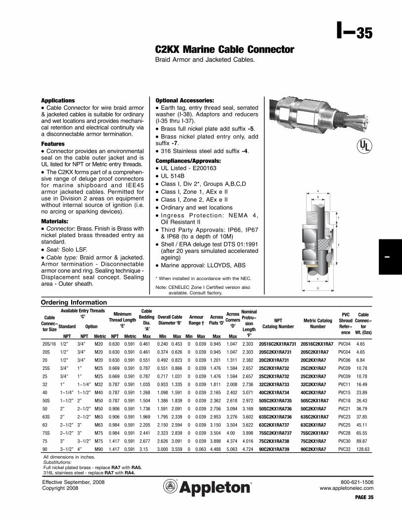
C2KX Marine Cable ConnectorBraid Armor and Jacketed Cables.
Applications• Cable Connector for wire braid armor & jacketed cables is suitable for ordinary and wet locations and provides mechani-cal retention and electrical continuity via a disconnectable armor termination.
Features• Connector provides an environmentalseal on the cable outer jacket and isUL listed for NPT or Metric entry threads.
• The C2KX forms part of a comprehen-sive range of deluge proof connectorsfor marine shipboard and IEE45armor jacketed cables. Permitted for use in Division 2 areas on equipment without internal source of ignition (i.e. no arcing or sparking devices).
Materials:• Connector: Brass. Finish is Brass withnickel plated brass threaded entry as standard.
• Seal: Solo LSF.
• Cable type: Braid armor & jacketed. Armor termination - Disconnectablearmor cone and ring. Sealing technique -Displacement seal concept. Sealing area - Outer sheath.
All dimensions in inches.Substitutions:Full nickel plated brass - replace RA7 with RA5.316L stainless steel - replace RA7 with RA4.
Effective September, 2008Copyright 2008
PAGE 36
800-621-1506www.appletonelec.com
I-36
I
Applications• A wide range of Thread Conversion Adaptors and Reducers for both Industrial and Hazardous Area applications, providinga means of connection between cable entry devices and equipment havingdis-similar threads.
Materials:• Adaptors and Reducers: Available in a variety of materials and finishes includingBrass, aluminum, stainless steel and non-metallic (e.g. nylon), with optional nickel plating of brass components.
The Hazardous Area versions can be supplied as Certified Components suitablefor use on any Zone 1 or Zone 2 approvedequipment having Flameproof Ex ‘d’,Increased Safety Ex ‘e ’ , or NonIncendive Ex ‘n’ / Ex ‘nR’ methods of protection. It should be noted that when using Component approved ThreadConversion Adaptors & Reducers inassociation with explosion protected elec-trical equipment the following basic rules must be observed in line with good engi-neering practice:
1. No more than one conversion adaptoror reducer should be used at one time on any given cable entry.
737 Series reducer
737 Series adaptor
Adaptors and Reducers
Dimensions: (See Table B on following page)
2. Stopping Plugs should be fitteddirectly into unused entries of the equipment, and not into an adaptor or reducer.
3. The female connection thread of a Thread Conversion Adaptor shall ‘step’ not more than one ‘size’ up from the male connection thread, or equal to one ‘size’ up in the case of a thread gender change.
Example: M20 (M) to M25 (F) or M20 (M) to 3/4" NPT (F) is permitted
Whereas M20 (M) to M32 (F) or M20 (M) to 1" NPT (F) is not permitted
Options:• Nickel Plated Brass add suffix -5.
• 316 Stainless Steel add suffix -4.
Dimension Data Table
To obtain 737 Adaptor and & Reducer nominal dimensions, follow the steps below:
1. Select the male thread using the left hand column of Table A.
2. Select the female thread using the column headings of Table A and cross referencing the data with the male thread selection from Step 1. Identify the key reference number prefi xed "A" for Adaptor or "R" for Reducer.
3. Using this key reference number, refer to the corre-
sponding dimensions in Table B (on following page).
Note: The data in both tables include Adaptors and Reducers that are certifi ed for use in Hazardous Areas. Dimensional data for other industrial versions is available upon request. Please contact Technical Support.
Applications• A comprehensive range of Stopper Plugs which are designed to close any unused entries in electrical equipment. In general care should be taken to en-sure that a suitable Entry Thread Seal-ing Washer is also selected and installed, where applicable, to ensure that an ef-fective seal is made at the entry, thereby maintaining the integrity of the enclosure or equipment I.P. rating.
Features• Catering to both Industrial and Haz-ardous Area applications the range cov-ers a number of different design types which are supplied in both metallic and non-metallic (e.g. Nylon) forms.
Materials:• Stopper plugs: Available in brass, aluminum, stainless steel and non-me-tallic nylon. Optional nickel plating of brass components also available.
Compliances/Approvals:• Hazardous Area cer t i f icat ion:ATEX 001284U (component).
• Equipment certification:ATEX 001003.
Class I, Div.2,Type 4X; Exd/Exe IP68
Stopper Plugs
Ex ‘d’ RecessedStopper Plug Type ‘A’
Ex ‘d’ RecessedStopper Plug Type ‘B’
747 Series Stopper Plug
Plug SizeA/F Socket
in mm747 SERIESMale Size
N’Plated BrassPart Number
M16 8 M16 747FAM15
M20 747FAM25
M20 10M25 747FAM35
M32 747FAM45
M25 10M40 747FAM55
M50 747FAM65
M32 10M63 747FAM75
M75 747FAM85
M40 10M90 747FAM95
1/2”NPT 747FAT15
M50 103/4”NPT 747FAT25
1”NPT 747FAT35
M63 141-1/4”NPT 747FAT45
1-1/2”NPT 747FAT55
M75 142”NPT 747FAT65
3”NPT 747FAT75
3-1/2”NPT 747FAT85
Optional ‘O’ Ring
Hexagon HeadStopper Plug
757 Series Stopper Plug
Plug Size757 SERIESMale Size
N’Plated BrassPart Number
M16M16 757DM15
M20 757DM25
M20M25 757DM35
M32 757DM45
M25M40 757DM55
M50 757DM65
M32M63 757DM75
M75 757DM85
M40M90 757DM95
1/2”NPT 757DT15
M503/4”NPT 757DT25
1”NPT 757DT35
M631-1/4”NPT 757DT45
1-1/2”NPT 757DT55
M752”NPT 757DT65
3”NPT 757DT75
3-1/2”NPT 757DT85
Effective September, 2008Copyright 2008
800-621-1506www.appletonelec.com
PAGE 41
I-41I
Stopper Plugs
Optional ‘O’ Ring
Mushroom HeadStopper Plug
767 Series Stopper Plug
Plug SizeA/F Socket
in mm767 SeriesMale Size
N’Plated BrassPart Number
NylonPart Number
— 6M16 767DM15 767ERM12
M20 767DM25 767ERM22
M16 8M25 767DM35 767ERM32
M32 767DM45 767ERM42
M20 10M40 767DM55 767ERM52
M50 767DM65 767ERM62
M25 10M63 767DM75 767ERM72
M75 767DM85 767ERM82
M32 10M90 767DM95 767ERM92
1/2”NPT 767DT15 767ERT12
M50 103/4”NPT 767DT25 767ERT22
1”NPT 767DT35 767ERT32
M63 101-1/4”NPT 767DT45 767ERT42
1-1/2”NPT 767DT55 767ERT52
M75 102”NPT 767DT65 767ERT62
3”NPT 767DT75 767ERT72
— 103-1/2”NPT 767DT85 767ERT82
Available Stopper Plug Options
Description Allen Key SlotMetallic Non-Metallic
Ex ‘d’ Ex ‘e’ Industrial Ex ‘e’ Industrial
747 Recessed Non-Tamper Proof Type ‘A’ X X
747 Recessed Tamper Proof Type ‘B’ X X
757 Hexagon Head X
757 Hexagon Headc/w ‘O’ ring seal X
767 Mushroom Head
767 Mushroom Headc/w ‘O’ ring seal
Effective September, 2008Copyright 2008
PAGE 42
800-621-1506www.appletonelec.com
I-42
I
Locknuts – Nickel Plated BrassBrass Locknuts are recommended for use in securing brass cable glands to a gland plate or into equipment.
350NPTLN5 350NPT 1Earth Tags – Pear (Nickel Plated Brass)Installed between the cable gland and equipment. Provide an earth bond connection as specified in BS 6121 : Part 5 : 1993.
Entry Thread Seals – Sealing (IP) WashersIt is essential to maintain the integrity of the degree of I.P. protection at which Explosion Proof equipment has been rated. The need for a Sealing Washer will depend on the I.P. rating, code of protection and the type of entry holes available within that equipment (e.g. for Ex e apparatus or ter-minal boxes which are permitted to have untapped through clearance holes it is necessary to fit a sealing washer to ensure that the minimum IP54 requirement is met). Other equipment with tapped entry holes may not require a sealing washer to maintain the rated integrity of the instal lation.Entry Thread Sealing Washers are produced in 2mm thick white nylon as standard which are recommended and meet the specified requirements of Shell’s Offshore operations.To verify the effectiveness of the nylon entry sealing washers, independent 3rd party tests to BS EN 60529:1992 have been conducted on certain Cable Gland types at IP66, IP67 & IP68 levels of protection. Documentation of these high standard tests is available upon request.
350NPTETS 350NPT 1Serrated Washers – Stainless SteelAvailable in Plated Steel or Stainless Steel as standard, these “shake-proof” Serrated Washers fitted internally to the equipment and before a locknut act as an anti-vibration device to prevent the gland and locknut arrangement from inadvertently loosening in service.
ShroudsPush on shrouds are used to minimise the risk of dirt or foreign substances gathering on the Cable Gland body, and/or point of cable to gland interface. Standard shrouds are produced in Black PVC. Refer to the specific cable gland page.
Cable Gland Accessories and Tools
Effective September, 2008Copyright 2008
800-621-1506www.appletonelec.com
PAGE 43
I-43I
Service Entrance HeadsThreaded Entrance Caps in Malleable Iron or Aluminum.
Applications• Designed for overhead service entrance to buildings to prevent rain from entering conduit.
Features• Simple construction; easy to install.
• Weather resistant.
• Variety of knockouts allows use with different sizes and numbers of wires.
• Cat. No. F125 thru F250 have exclu-sive snap-on covers.
Standard Materials• All bodies and caps are malleable iron except for F125 thru F250 which are aluminum.
• Phenolic insulators.
Standard Finish• Triple coat— (1) zinc electroplate, (2) dichromate, and (3) epoxy powder coat.
• Aluminum: natural finish.
Size Range• 1/2” thru 2 1/2”.
• 5” thru 6”.
Compliances• UL Standard 514B.
• CSA Standard C22.2 No. 18. Number ofCatalog Size and Dia. of Dimensions (In.)Number (In.) Holes A B C
Malleable Iron Threaded Entrance CapsF50 1/2 (4) 5/16” 2-3/4 2-5/32 2-9/32F75 3/4 (3) 13/32” and (2) 3/8” 3-5/32 2-9/32 2-15/32F100 1 (3) 1/2” and (2) 7/16” 3-13/16 2-21/32 2-29/32
Aluminum Threaded Entrance Caps with Exclusive “Snap-On” CoverF125 1-1/4 (3) 5/8” and (2) 7/16” 4-5/16 2-7/8 3-5/8F150 1-1/2 (3) 3/4”, (2) 19/32” 5 3-5/16 4-11/32 and (1) 7/16”F200 2 (3) 1”, (2) 3/4” and (1) 17/32” 6-11/32 4-1/2 5-9/16F250 2-1/2 (3) 1-5/16”, (3) 7/8” and (1) 1” 9 6-1/4 7-3/4
Expansion Couplings and Bonding Jumpers for Rigid Metal ConduitAvailable for 4-inch or 8-inch conduit movement.
Applications• To accommodate linear movement of conduit installations caused by ther-mal expansion and contraction and by structural shift.Features• Weatherproof.
• Concrete tight.
• Durable construction.
• Corrosion resistant finish.
• UL listed and CSA Certified with bonding jumpers in indoor and outdoor locations.Standard Materials• Fitting body and cap—malleable iron.
• Grounding ring—braided and tinned copper wire.
• Packing seal—lubricated textile fiber.
• Bushing—phenolic plastic.
• Washer—zinc plated steel.
• Gasket—fiber stock.
• Body (6” size only)—zinc plated steel.Standard Finishes• Fitting body and cap—hot dipped galvanized.
• Other components par ts—see standard materials information.Size Range• 1/2” thru 5”, 4” conduit movement.• 1/2” thru 6”, 8” conduit movement.Compliances• UL 514B
• CSA C22.2 Number 18
• Federal spec WF-408E
• NEMA FB1
Bonding JumpersApplications• To ensure bonding and grounding continuity between segmented rigid metal conduit runs and for use with expansion couplings as required by NEC 250.98.Standard Materials/Finishes• C l a m p s — m a l l e a b l e i r o n , h o t d i p p e d z i n c g a l va n i ze d .• Strap—copper braid, tin plated.• Hardware—steel, mechanical zinc plated.Size Range• 1/2” thru 6” conduit sizes.
“XJ” Expansion Couplings Use with Bonding JumperTrade Dimensions in inches StrapSize Catalog Max. Dia. Overall Length Catalog Length(In.) Number A B Number (In.)
Deflection and Expansion Couplings for RMC and IMC
Applications• These couplings, for rigid metal conduit or IMC will provide a flexible and watertight connection for protec-tion from damage due to any type movement.
• For installation indoors, outdoors, buried underground or in concrete (center of fitting is to be in the center of the joint between two sections of concrete).
Features • Designed for linear expansion (up to 3/4”) or contraction (up to 3/4”) of conduit or for misalignment of axes of coupled conduit runs in any direction angular (up to 30°) or parallel (up to 3/4”).
• Dampens vibrations between two sections of coupled conduit. The internal copper bonding jumper has the capacity to carry ground fault currents equal to the conductor sizes required by UL and the NEC.
Standard Materials• Hot-dip galvanized finished ductile iron couplings.
• Molded Neoprene sleeve.
• Tinned flexible copper braid bonding jumper.
• Stainless steel clamping bands.
Compliances• Watertight (NEMA 4), raintight and concretetight.
Normal Expansion Contraction Misalignment Misalignment (up to 3/4”) (up to 3/4”) Angular Parallel (up to 30°) (up to 3/4”)
Effective September, 2008Copyright 2008
PAGE 46
800-621-1506www.appletonelec.com
I-46
I
Conduit Hubs for Threaded RMC and IMCClass I, Div. 2Class II, Div. 1 and 2Class IIINEC 501-4(b), 502-4(a)(b),503-3(a)
Applications• Uni-seal conduit hubs are used for installing threaded rigid and IMC conduit systems into sheet metal enclosures, eliminating the need for welded hubs.
Features• Patented (space saving) hex-hub wedge adaptor fits nearly flush against inside walls of enclosures.
• Single wrench installation, simple two-piece construction.
• Protective flame-resistant insulated throat eliminates any need for end bushings.
• Locking edge of body bites into enclosure wall, makes hub self-locking, eliminates the need for lock-nuts, provides continuous 360° pres-sure on both sides of enclosure, forms positive grounding and vibration-resis-tant connection.
• Built-in recessed neoprene gasket.
• Full, machined tapered threads (NPT).
Standard Materials• HUB-50 thru HUB-100; steel.
• HUB-125 thru HUB-600 and HUB-9050 thru HUB-90100: malleable iron.
Applications• For use at intermediate locations to facilitate wire pulling through long runs of rigid conduit.
• For wet (PBFW Weatherproof) or dry (PBF non-weatherproof) loca-tions.
• For vertical or horizontal runs of rigid conduit.
Features • Convenient and economical wire pulling.
• Provides safe ground continuity.
• Type PBFW (Weatherproof) con-nector fitting consists of two end bushings—one threaded, one pre-cision bored with three set-screws, braided grounding ring, washer packing gland and insulating bush-ing.
• Type PBF (non-weatherproof) same as PBFW except without braided grounding ring, washer and braided packing ring.
Standard Materials• End bushings are malleable iron finished with zinc electroplate, di-chromate and epoxy powder coat.
• Setscrews are steel finished with zinc electroplate.
• Grounding ring is a preformed braided copper packing.
• Washer is steel finished with zinc electroplate.
• Insulating bushing is polypropyl-ene.
• Packing Gland for PBFW Series is a preformed braided ring.
Size Range• 1/2” through 4” trade (hub) size.
Compliances• N.E.C. article 370-18(a)(1).
SLEEVE
Braided Copper Grounding Ring Packing Gland
TYPE PBF
TYPE PBFW
Effective September, 2008Copyright 2008
PAGE 48
800-621-1506www.appletonelec.com
I-48
I
Shaded area indicates items suitable for Class I, Group A in addition to Class I, Groups B,C,D; Class II, Groups E,F,G and Class III. † Class I, Groups C,D; Class II, E,F,G; Class III. * Not UL Listed,
Reducing Bushings for Threaded RMC and IMCClass I, Groups A,B,C,DClass II, Groups E,F,GClass III
Applications• RB reducing bushings are designed to reduce conduit hubs to a smaller size and are used in threaded rigid and IMC conduit systems.
Features • Smooth, rounded integral bushing protects conductor insulation.
• Full, machined tapered threads (NPT).
Standard Materials• RB50-13 thru RB200-150: Steel.
• RB250-100 thru RB600-500: Malleable Iron.
• RB50-13A thru RB600-500A: Aluminum
Standard Finishes• Steel bushings: zinc electroplate.
• Malleable iron bushings: zinc electroplate, dichromate and epoxy powder coating.
Conduit Cable Tray Clamps and Grounding Conductor ClampType TCC Single and TCCD Double Supporting Clamps, and TCGC Grounding Clamp.
Applications: TCC and TCCD• For supporting rigid conduit to cable tray flange at each location where tray cable exits the tray and is run through rigid conduit raceway to control panel boards, motor starters and other elec-trical devices.
Applications: TCGC• To provide a means for securely at-taching a grounding conductor to cable tray to maintain grounding continuity for the entire cable tray system.
• To protect equipment through a reliable method for carrying ground fault currents.
• For installation indoors or outdoors, with most types of cable trays with in-side or outside flanges.
Features: TCC and TCCD• Clamps mount on all types of tray configurations (inside, outside or dou-ble flange).
• Exclusive design provides full 360° swivel, allowing exit conduit position-ing at any angle, eliminating the need for separate inside or outside flange clamps, and field modification.
• Unique clamp mounting provides greater cable capacity and working area within the tray by reducing inter-nal clamp obstruction.
• Exclusive TCCD double conduit clamps conserve space where multiple cables exit the tray at one location.
• Only four clamps fill needs for all conduit sizes from 1/2” thru 4”.
• Fewer catalog numbers reduce job-site inventory and the chances of er-rors and confusion.
Features: TCGC• Meets requirements of NEC Articles 250.4(A)(3) and 392.6(J) for grounding and bonding.
• Quick and easy installation—low in-stalled cost. No drilling or special tools required.
• Accommodates solid (where suit-able) or stranded aluminum or copper grounding conductors from #6 to 2/0.
• Setscrew bonds the clamp to the tray and another setscrew securely attaches the grounding conductor to
the clamp—outstanding pull-out and vibration resistance.
Standard Materials• TCC and TCCD base and conduit clamp are malleable iron. Hot dipped galvanized finish.
• TCGC has copper free aluminum body, tin electroplated.
• Nuts, bolts and other hardware are steel. Mechanically galvanized finish.
Size Range• Type TCC (single conduit clamp) avail-able in 1/2” through 4” conduit size.
• Type TCCD (double conduit clamp) available in 1/2” through 2” conduit size.
• Type TCGC accommodates wire sizes #6 to 2/0.
Compliances• UL Standard 467.
Catalog RigidNumber Size (In.)
Type “TCC” Cable Tray Clamp for Single Line ConduitTCC-50100G 1/2, 3/4, 1
TCC-125200G 1-1/4, 1-1/2, 2
TCC-250300G 2-1/2, 3
TCC-350400G 3-1/2, 4
Type “TCCD” Cable Tray Clamp for Double Line ConduitTCCD-50100G 1/2, 3/4, 1
TCCD-125200G 1-1/4, 1-1/2, 2
Type “TCGC” Cable Tray Grounding Conductor ClampTCGC For ground wire sizes #6 to 2/0
Effective September, 2008Copyright 2008
800-621-1506www.appletonelec.com
PAGE 53
I-53I
Liquidtight Connectors and Hubs for Liquidtight Flexible Metal ConduitGeneral Information and special features.
Applications• Seal out oil, water, dirt, dust and fumes wherever liquidtight flexible metal conduit is used.
• Typical applications include food processors, beverage plants, chemical plants, dairies, machine shops, plastic fabricators, petroleum machinery, and gantry cranes.
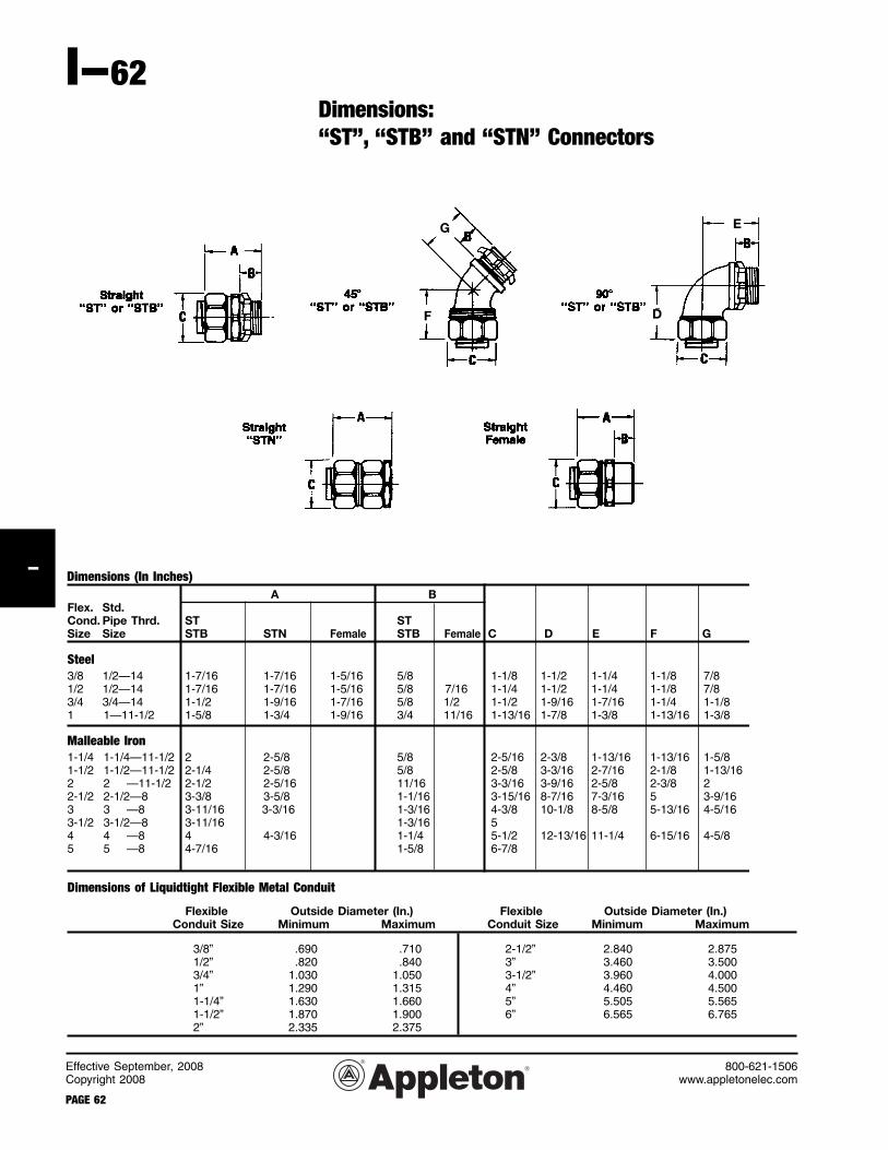
ST and STB SeriesFor connections to threaded hubs. Insulated throat on STB protects conductors. Connectors are available with grounding lugs. Straight sizes 3/8” thru 5”; 45° and 90°, 3/8” thru 4”. Straight and 90° styles in sizes 3/8” thru 2” also available with certain metric thread sizes. See page I-49.
STN Space-Saving Connectors for En-closuresAppleton STN Series makes liquidtight connections to sheet metal enclosures. Space-saving, self-locking gasketed wedge forms a perfect seal and allows more wiring room. Straight sizes 3/8” thru 4”; 90° sizes 3/8” thru 1”.
STG Neoprene Sealing Gasket AssemblySteel backed, neoprene gasket assem-bly assures a liquidtight connection to a rough metal surface such as knock-outs in steel junction boxes. Sizes 1/2” thru 4” feature bonded gasket/retainer assembly. 1/4 and 3/8 available in thermoplastic material.
Female Steel ST ConnectorsFor liquidtight connections to threaded rigid metal conduit. Sizes 3/8” thru 1”.
Features • Extra-long ferrule resists pull-outs. All Appleton liquidtight fittings feature a one-piece, deep-grip ferrule design that simplifies installation and prevents conduit sleeving. Its extra length and sharply defined threads provide greater surface contact with the conduit for excellent grounding continuity, greater pull-out strength (4X UL requirements)...and added protec-tion against excessive external conduit flexing and vibration. It virtually elimi-nates the need for an external strain relief in many applications.
• External grounding lugs available on all Appleton liquidtight connec-tors. Where National Electrical Code permits an external equipment bonding jumper, [NEC sections 250-96(b), 501-16(b) and 502-16(b)], Appleton ST and STB connectors are offered with an in-tegral bonded steel zinc electroplated lug. Cut-away view shows extended ferrule design for maximum ground-ing effectiveness. Grounding lugs also available in STN, STL and Female ST Series. Consult factory.
• Wire mesh strain relief available on all STB, STN, and female ST con-nectors. Woven stainless steel mesh sleeve alleviates flexing stress at liq-uidtight connection.
Effective September, 2008Copyright 2008
PAGE 54
800-621-1506www.appletonelec.com
I-54
I
Installation Features of “ST”, “STB”and “STN” Connectors and Hubs for Liquidtight Flexible Metal Conduit
Liquidtight Connectors
A
B
Liquidtight Hubs
Sealing Gasket
Neoprene sealing gasket eliminates common connection problems and assures a liquidtight installation. Seals against oil, water, dirt and chemicals.
Space Saving Hex-HubWedge Adapter
Male shank of unique Appleton hex-hub wedge adapter “finger tightens” into connector body. Flared surface of adapter wedges box wall against lock-ing edge of body. Forms full 360° con-tact on both sides of box wall.
Insulated Throat
Insulating insert recessed into hex-hub wedge adapter protects against wire damage...without reduction in throat diameter. Perfect for extreme vibration conditions. Nothing to come loose, de-teriorate, crack or break!
Using hacksaw, cut liquid-tight flexible conduit mak-ing certain that the jacket and conduit are flush. (A) Place compression nut over conduit. (B) Screw ferrule onto the spiralled steel inner wall of the conduit. The firm grip of the ferrule threading against the inner conduit wall provides a continuous, permanent, positive metal-to-metal ground. There are no sharp edges to cause injury to wire during or after installation. (C) Place the liquidtight flexible conduit with the ferrule into con-nector body. (D) Tighten compression nut as far as i t wi l l go. This wi l l assure correct collaring of the conduit—the end of the metal edge of the ferrule will curve out slightly (E) This prevents damage to the conduit jacket itself at the time of installa-tion, and also insures against future damage from frequent flexing, jarring or vibration.
C
D
E
Effective September, 2008Copyright 2008
800-621-1506www.appletonelec.com
PAGE 55
I-55I
Liquidtight “ST” and “STB” Connectors for Liquidtight Flexible Metal ConduitST Series with plain throat; STB Series with insulated throat.
Class I, Div. 2Class II, Div. 1 and 2Class IIINEC 501-4(b), 502-4(a)(2), 503-3(a)
Applications• Provides a dependable connection for liquidtight flexible metal conduit. Seals out oil, water, dust, dirt and fumes.
Features• ST Series has plain throat; STB Series has insulated throat to protect against wire damage.
• Unique long ferrule with more pronounced threads provides over four times UL pull-out requirements.
• Ferrule also provides maximum surface contact for better sealing and a continuous, permanent, positive metal-to-metal ground.
• Liquidtight/raintight/oiltight.
• Suitable for wet locations.
• Full, machined tapered threads (NPT).
• Compact design with small turning radius.
Standard Materials• 3/8” to 1” (straight): steel.
• 1-1/4” to 5” (straight) and 3/8” to 4” (45° and 90°): malleable iron.
• Ferrule: (3/8” to 1”) steel; (1-1/4” to 5”) aluminum.
Standard Finishes• Steel-zinc electroplate.
• Malleable iron-zinc electroplate, di-chromate and epoxy powder/zinc elec-troplate.
Size Range:• 3/8” thru 5” conduit size (straight)
• 3/8” thru 4” conduit size (45° and 90°)
Compliances• UL Standard 514B.
• CSA Standard C22.2 No. 18
• Suitable for hazardous locationsClass I, Div. 2Class II, Div. 1 and 2Class III, Div. 1 and 2NEC 501-4(b), 502-4(a)(2), 503-3(a)
For connector dimensions, see page I-48.
ST Connectors
Straight 45° 90°
Catalog Size Catalog Size Catalog SizeNumber (In.) Number (In.) Number (In.)
Liquidtight “ST” and “STB” Connectors with External Grounding Lugs for Liquidtight Flexible Metal ConduitST Series with plain throat; STB Series with insulated throat.
Class I, Div. 2Class II, Div. 1 and 2Class IIINEC 501-4(b), 502-4(a)(2), 503-3(a)
Applications• For use with liquidtight flexible metal conduit where an external, visible equipment bonding jumper is desired.
Features• ST-L Series has plain throat; STB-L Series has insulated throat to protect against wire damage.
• Unique long ferrule with more pronounced threads provides over four times UL pull-out requirements.
• Ferrule also provides maximum surface contact for better sealing and a continuous, permanent, positive metal-to-metal ground.
• Adequately sized bonded lugs provide excellent grounding continuity and allow for visible ground path inspection.
• Liquidtight/raintight/oiltight.
• Suitable for outdoor use.
• Full, machined tapered threads (NPT).
Standard Materials• 3/8” to 1” (straight): steel.
• 1-1/4” to 5” (straight) and 3/8” to 4” (45° and 90°): malleable iron.
• Ferrule: (3/8” to 1”) steel; (1-1/4” to 5”) aluminum.
Standard Finishes• Steel-zinc electroplate.
• Malleable iron—zinc electroplate, dichromate and epoxy powder/zinc electroplate.
Liquidtight Flexible Metal ConduitConnectors with Wire Mesh Strain ReliefSTB, STN, and Female ST Types.
Applications• For use with liquidtight flexible metal conduit subjected to flexure, vibration, motion, or strain. “STB” Type connects to threaded hubs. “STN” Type is for connections to sheet metal enclosures. Female ST Type connects to threaded rigid conduit and IMC.
Features• Unique long ferrule with more pronounced threads provides over four times UL pull-out requirements.• Ferrule also provides maximum surface contact for better sealing and a continuous, permanent, positive metal-to-metal ground.• Stainless steel wire mesh prevents pull-out of flexible conduit from fitting.• Insulated throat (STB and STN Series) protects against wire damage.• STN Type has space-saving hex hub wedge adapter that fits nearly flush
against inside walls of enclosures, providing maximum wiring room.• Liquidtight/raintight/oiltight.• Suitable for wet locations.• STB Series has full, machined tapered threads (NPT).
Standard Materials• Straight STB, STN, and Female ST connectors—3/8” to 1” are steel, 1-1/4” and over are malleable iron.• 45° and 90° connectors—all sizes are malleable iron.• Ferrule—3/8”to 1” are steel; 1-1/4” and over are aluminum.• Wire Mesh—stainless steel.
Standard Finishes• Steel—zinc electroplate.• Malleable iron—zinc electroplate, di-chromate and epoxy powder/zinc elec-troplate.
Size Range:• All STB, Female ST and straight STN connectors: 3/8” thru 3” conduit size.• STN 90° connectors: 3/8” thru 1” conduit size.
Compliances• UL Standard 514B.• CSA Standard C22.2 No. 18• Suitable for hazardous locationsClass I, Div. 2Class II, Div. 1 and 2Class III, Div. 1 and 2NEC 501-4(b), 502-4(a)(2), 503-3(a)
For Wire Mesh Strain Relief (with cap) only, see catalog Section ST.
Catalog Size Catalog SizeNumber (In.) Number (In.)
• Suitable for hazardous locationsClass I, Div. 2Class II, Div. 1 and 2Class III, Div. 1 and 2NEC 501-4(b), 502-4(a)(2), 503-3(a)
For connector dimensions, see page I-48.
Effective September, 2008Copyright 2008
PAGE 60
800-621-1506www.appletonelec.com
I-60
I
Liquidtight “ST-F” Female Connectorsand “STG” Sealing Gaskets for LiquidtightFlexible Metal Conduit Connectors
Applications• Female ST ConnectorsFor use with liquidtight flexible metal conduit when making connection to threaded rigid conduit and IMC.
• STG Sealing GasketsGaskets provide a positive seal between shoulder of male hub connector and sheet metal enclosure.
Features• All ST Connectors have a unique long ferrule with more pronounced threads that provide over four times UL pul l -out requirements. The ferrule also provides maximum surfacecontact for better sealing and a continuous, permanent, positive metal-to-metal ground.
• Liquidtight/raintight/oiltight.
• Suitable for wet locations.
• Full, machined tapered threads (NPT).
• Female ST Connectors have compact design with small turning radius.
• STG Sealing Gaskets in sizes1/4” and 3/8” are one piece elastomeric gaskets. Sizes 1/2” thru 6” have unique bonded gasket/retaining-ring assembly for easy installation. Standard Materials
• ST Connectors: 3/8” to 1”—steel with steel ferrule; 1-1/4” to 4”—malleable iron with aluminum ferrule.
• STG Sealing Gaskets: 1/4” and 3/8”—elastomericmaterial; 1/2” to 6”—steel retaining ring with bonded neoprene gasket.
Compliances• UL Standard 514B.• CSA Standard C22.2 No. 18.• Suitable for hazardous locationsClass I, Div. 2Class II, Div. 1 and 2Class III, Div. 1 and 2NEC 501-4(b), 502-4(a)(2), 503-3(a)
• STG Sealing Gaskets are UL listed raintight when used with raintight enclosures and Appleton Liquidtight and Cord Grip fittings.
Catalog Size Catalog SizeNumber (In.) Number (In.)
“PG” and “ISO” Metric Thread Liquidtight Insulated Connectors for Liquidtight Flexible Metal Conduit
Applications• Provides a dependable connection for liquidtight flexible metal conduit.
Features• Unique long ferrule with more pro-nounced threads provides over four times UL pull-out requirements. The ferrule also provides maximum sur-face contact for better sealing and a continuous, permanent, positive metal-to-metal ground.
• Insulated throat protects against wire damage.
• Liquidtight/raintight/oiltight.
• Suitable for wet locations.
• Full, machined metric threads.
• Compact design with small turning radius.
Standard Materials• 3/8” to 1” (straight): steel.
• 1-1/4” to 2” (straight) and 3/8” to 2” (45° and 90°): malleable iron.
• Ferrule: (3/8” to 1”) steel; (1-1/4” to 2”) aluminum.
• Insulators: Nylon.
Standard Finishes• Steel-zinc electroplate.
• Malleable iron—zinc electroplate, dichromate and epoxy powder coat.
Size Range• 3/8” thru 2” conduit size.
Compliances• UL Standard 514B, File No. E14814. CSA File No. 65178.
• “PG” Metric Thread—German indus-try Std. DIN 40430.