68
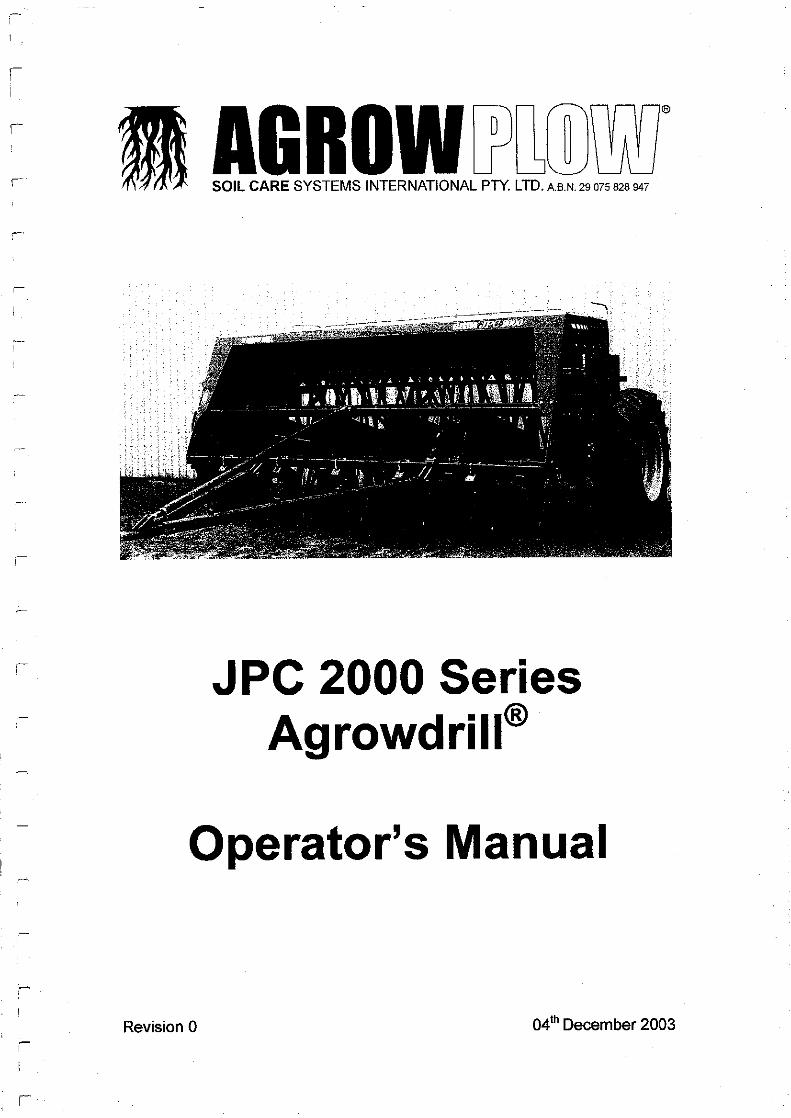
i I r - ' . I r I AG ROW DJUWITJJ SOIL CARE SYSTEMS INTERNATIONAL PTY. LTD. AB.N. 29 075 828 947 JPC 2000 Series Agrowdrill® Operator's Manual Revision 0 04 th December 2003
i I
r
-'
. I
r
I
AG ROW DJUWITJJ SOIL CARE SYSTEMS INTERNATIONAL PTY. LTD. AB.N. 29 075 828 947
JPC 2000 Series Agrowdrill®
Operator's Manual
Revision 0 04th December 2003


JPC 2000 Series Agrowdrill
Agrowplow Soil Care Systems International Pty Ltd
ABN 29 075 828 947
Contact Details
134 Thornton Street WELLINGTON NSW 2820
PO Box 270 WELLINGTON NSW 2820
Phone: 02 6845 1566 FAX: 02 6845 1603
Email: [email protected]
Website: www.agrowplow.com
II i Quality ' Endorsed i Company i 150il001 UCIIWT ; -do,do Aurttllllt
'Prosperity Through Soil Care'
Page i


JPC 2000 Series Agrowdrill
Table of Contents
1.0 Safety ....................................................................................................... 1 1.1 Safety is the Operators responsibility ................................................ 1 1.2 Safe Operation Needs a Qualified Operator ...................................... 1
1.2.1 Understand the Instructions, Rules and Regulations ................ 1 1.2.2 Have Training with Actual Operation ......................................... 1 1.2.3 Know the Work Conditions ........................................................ 2
1.3 Safety Instructions ............................................................................. 2
2.0 J PC 2000 Series Specifications .............................. 4
3.0 Principles of Direct Drilling ..................................... 6 3.1 Weed Control. .................................................................................... 6 3.2 Timing ................................................................................................ 6 3.3 Seed .................................................................................................. 6 3.4 Seed Placement ................................................................................ 7 3.5 Ensure Adequate Plant Nutrition ....................................................... 7 3.6 The Job's Not Finished at Seeding .................................................... 8
3.6.1 Weed Control ............................................................................ 8 3.6.2 Insect Pest Control .................................................................... 8 3.6.3 Use of Fertiliser ......................................................................... 8 3.6.4 Grazing Management.. .............................................................. 9
4.0 Hectaremeter Installation ...................................... 1 O 4.1 Installation Procedure ...................................................................... 10 4.2 Hectaremeter Shaft Sensor Installation ........................................... 11
5.0 Operating lnstructions ........................................... 13 5.1 Hitching and Levelling ...................................................................... 13
5.1.1 Hitching ................................................................................... 13 5.1.2 Hydraulic Lift Circuit ................................................................ 13 5.1.3 Levelling .................................................................................. 15
5.2 Tyre Pressures ................................................................................ 15 5.3 Seeding Depth ................................................................................. 15 5.4 Row Spacing ................................................................................... 16 5.5 Operating Speed .............................................................................. 16 5.6 Hopper Selection ............................................................................. 16
Page ii


JPC 2000 Series Agrowdrill
6.0 Calibration Instructions ......................................... 17 6.1 Farmscan 1100 Hectaremeter ......................................................... 17 6.2 Operation of the Hectaremeter ........................................................ 17 6.3 Calibrating the Hectaremeter ........................................................... 18 6.4 Metering Rates ................................................................................ 19 6.5 Method for Checking Metering Rates .............................................. 19
6.5.1 Calibration Procedure .............................................................. 20 6.6 Field Calibration ............................................................................... 21 6. 7 Plotting Calibration Charts ............................................................... 22 6.8 Adjusting the Seed and Fertiliser Rates ........................................... 22
6.8.1 Gearbox Adjustments .............................................................. 22 6.8.2 Restrictors ............................................................................... 23 6.8.3 Gate Settings .......................................................................... 24
6.9 Calibration Charts ............................................................................ 24 6.10 Agrowdrill Calibration Settings ......................................................... 32
7 .0 Operating Tips ........................................................ 33 7.1 After the First Round ........................................................................ 33 7.2 Gradual Slowing of Fertiliser Flow ................................................... 33 7.3 Seizing of the Metering System ....................................................... 33 7.4 Checking the Rotation of the Drives ................................................ 34 7 .5 Cleaning Seed and Fertiliser Hoppers ............................................. 34
8.0 Lubrication and Maintenance ............................... 35 8.1 Pre-Operation Check ....................................................................... 35 8.2 Daily Service .................................................................................... 35 8.3 Lubrication ....................................................................................... 35 8.4 Replacing Soil Openers ................................................................... 36 8.5 Downtube Assembly ........................................................................ 36 8.6 Replacing Adjustable Gates ............................................................ 37 8.7 Servicing Fluted Rollers ................................................................... 37
8. 7 .1 Drive Sprocket Bearings .......................................................... 37 8.7.2 Fluted Rollers .......................................................................... 37 8.7.3 Drive Shaft Mounting Bushes .................................................. 38
8.8 Major Servicing of the Metering Mechanism .................................... 38 8.9 Servicing the Gearboxes ................................................................. 39 8.10 Drive Chain Adjustments ................................................................. 39 8.11 Drive Chain Maintenance ................................................................ 40 8.12 Hectaremeter Sensor and Cable ..................................................... 40 8.13 Hectaremeter Multimeter Test ......................................................... 40
8.13.1 Reed Type Sensor .................................................................. 40 8.13.2 Sensor Cable ........................................................................... 41
8.14 End of Season Storage .................................................................... 41
9.0 Trouble Shooting ................................................... 42 9.1 Underframe ...................................................................................... 42 9.2 Metering System .............................................................................. 44 9.3 Hydraulics ........................................................................................ 46 9.4 Hectaremeter ................................................................................... 47
Page iii


JPC 2000 Series Agrowdrill
1.0 Safety
1.1 Safety is the Operators Responsibility
The Agrowdrill is a robust and versatile direct drill capable of operating under a wide variety of conditions. It can be used for direct drilling applications as well as traditional cultivation and seeding to maximise seed germination and plant establishment for pastures, summer crops, cereals, oil seeds and legumes.
The Agrowdrill presents an operator with hazards associated with setting up, on and off road transport, tillage and seeding applications, as well as machine service and maintenance. The operator must be aware of these hazards.
The dealer will explain the capabilities, safe application, service requirements .and restrictions of the Agrowdrill and demonstrate the safe operation of the Agrowdrill according to Soil Care Systems International instructions. The dealer can also identify unsafe modifications or use of unapproved attachments.
The following publications provide information on the safe use and maintenance of the Agrowdrill and attachments:
• The operator's manual delivered with the Agrowdrill gives operating information as well as routine maintenance and service procedures. It is a part of the Agrowdrill and must stay with the machine if it is sold. Replacement operator's manuals can be ordered from your Agrowplow Dealer.
• The Agrowdrill has machine decals that instruct on safe operation and care.
1.2 Safe Operation Needs a Qualified Operator
1.2.1 Understand the Instructions, Rules and Regulations
• The written instructions for the operation of the Agrowdrill are included in the Agrowdrill operator's manual and on the machine decals.
• Check the rules and regulations for your location. These rules may include any Federal and State safety requirements.
1.2.2 Have Training with Actual Operation
• Operator training must consist of a demonstration and verbal instruction. This training is given by your dealer when the Agrowdrill is delivered.
Page 1


JPC 2000 Series Agrowdrill
• New operators must start in an area without bystanders and use all the controls until they can operate the Agrowdrill safely under all conditions of the work area.
1.2.3 Know the Work Conditions
• Operators must know any prohibited uses or work areas. They need to know about excessive slopes and rough terrain.
• Operators must know the local road transport regulations, and understand the dangers and requirements of transporting wide and heavy equipment.
• Always wear protective clothing when maintaining or servicing the Agrowdrill.
• For operators to be qualified, they must not use drugs or alcoholic drinks that impair their alertness or coordination while working. Operators who are taking prescription drugs must get medical advice to determine if they can safely operate a machine.
1.3 Safety Instructions
READ THESE SAFETY INSTRUCTIONS CAREFULLY BEFORE ALLOWING ANY PERSON TO OPERATE THE AGROWDRILL
1. Review this manual before each season of use. 2. Never allow anyone unfamiliar or untrained to operate the implement 3. Operators must know and abide by any road transport regulations
pertinent to the transit of your Agrowdrill. 4. Never leave the Agrowdrill in a raised position. Accidental release of
control levers or hydraulic hose failure will result in the machine dropping. This can cause serious injury to someone near or under the implement.
5. Do not transport the Agrowdrill without the tractor drawbar being in a locked position. Transporting without the drawbar locked will result in loss of implement control and serious damage or injury.
6. Do not transport an Agrowdrill in excess of 20 kph. Transporting at greater speeds will result in loss of implement control and cause serious damage or injury.
7. Do not transport an Agrowdrill with a vehicle of less gross mass than that of the Agrowdrill being towed. Transporting with a smaller lead vehicle will result in loss of implement control and cause serious damage or injury.
8. Do not pull the Agrowdrill from any point other than from the tractor drawbar. Pulling from a point other than the designated tractor drawbar can result in tractor instability and cause serious damage or injury.
9. Extreme caution should be used when clearing coulters, tynes or soil openers. These may be very sharp and cause serious injury.
10. Do not ride on an Agrowdrill at any time.
Page 2


JPC 2000 Series Agrowdrill
11. Use due care when adjusting or maintaining any aspect of the Agrowdrill. Failure to do so may result in serious injury.
12. When undertaking maintenance on the Agrowdrill the operator must ensure that the tractor is turned off and the hydraulics are fully lowered. Accidental release of control levers or hydraulic hose failure will cause the implement to drop down. This can cause serious injury to someone near or under the machine.
13. If the Agrowdrill must be in a raised position for service or maintenance, ensure the unit is securely supported with proper support stands or the cylinder stoppers supplied with your Agrowdrill. After the implement is secured release the hydraulics on to the supports and stop the tractor engine before starting work. If supports are not used accidental release of control levers or hydraulic hose failure will cause the implement to drop down. This can cause serious injury to someone near or under the machine.
14. Do not remove any safety instruction decals. 15. Ensure that any safety decals are clear and visible. Clean and replace
as necessary.
Page 3


JPC 2000 Series Agrowdrill
2.0 JPC 2000 Series Specifications
Model
Frame Width
Box 1 & 4 Each
Box 2 & 3
Number of Toolbars
Toolbar Spacing
Underframe Clearance
Maximum Number of Sowing Rows
Drawbar Power kW
Required HP
Wheel Equipment
Wheel Centres
-
Transport & Shipping
Width
Height
Length
Unladen Mass
Depth Control
Main Frame
Trailed Hitch
Hopper
20R 24R 28R 32R
3.6m 4.2m 5.1m 5.7m
527 litres 612 litres 741 litres 827 litres
479 litres 558 litres 675 litres 753 litres
5
0.5m
0.67m with 732 Coil Tyne
24 28 34 38
65-75 70-90 85-105 100-140
85 - 100 90 - 120 115-140 130-190
18.4 x 34 Lugged Tyre
4.6m 5.2m 6.0m 6.7m
5.01m 5.6m 6.5m 7.1m
2.34m
3.04m
3000kg 3400kg 3800kg 4200kg
Hydraulic rephasing cylinders with manual depth adjustment.
5 bar standard 100 x 100 x 6mm High Tensile RHS with 350 grade end walls and centre supports.
A-frame is a rigid construction made from High Tensile 100 x 100 x 6mm RHS with heavy duty levelling tube assembly.
Construction of 2mm and 5mm HRC to resist corrosion.
Page4


JPC 2000 Series Agrowdrill
Metering Mechanism
Transmission
Optional Equipment
2 Large 70mm diameter dual row fluted rollers (fine and course seed) per outlet. Made from glass filled nylon and finished to a non-stick, low friction surface.
Single lever control for each hopper compartment. Fully enclosed transmission housing. Infinite speed variation from zero to maximum rates. Single lever control of gate settings giving infinite variation of gate clearance under distributors allowing easy adjustment for varying seed sizes.
Standard Coil Tyne 700 Series Coil Tyne 732 Series Coil Tyne Extension Stubs Front or Rear Platform Single and Double Outlet Feed Cups 2nd and 3rd Seeding Tubes Fabricated or Cast Sowing Boots Internal Lid Assemblies Fertiliser Screens Baffles Rear Seed Tube Rack Rear Hitch with Hydraulic Couplings
Figure 2.1: JPC 2000 Series Agrowdrill
Page 5


JPC 2000 Series Agrowdrill
3.0 Principles of Direct Drilling
3.1 Weed Control
Good weed control is essential for successful establishment of a new crop or pasture.
Weed control is one of the main reasons for traditional cultivation practices -the ground-engaging tool physically cuts and tears the roots of unwanted plants from the soil.
Direct drilling calls for a different approach. Some of the alternatives available for weed control include:
• Heavy grazing • Spraying with herbicides • Slashing • A combination of the above
3.2 Timing
Timeliness of the seeding operation is critical for good germination, growth and best yield results.
There are two main aspects of timeliness you must consider: • Always check the optimum seeding date for your district and seed on
time. • Ensure the best use of available moisture after rain by seeding while
the soil is moist.
3.3 Seed
Use only good quality certified seed. Certified seed is guaranteed to meet a minimum standard germination percentage and to be free of weed seeds and impurities. Use the recommended seeding rate.
Your seed supplier or your local advisory officer can tell you how many kilograms per hectare (kg/Ha) you should sow. Adequate plant population will also help your establishing crop or pasture compete with weeds.
Be sure to inoculate legume seed with the correct strain of Rhizobia bacteria. Failure to inoculate could lead to a poor pasture stand. Talk to your seed supplier about inoculation and ask them to supply the inoculant.
Page 6

JPC 2000 Series Agrowdrill
Your seed supplier will also be able to advise about chemical protection of your seed for insect attack and various soil borne diseases.
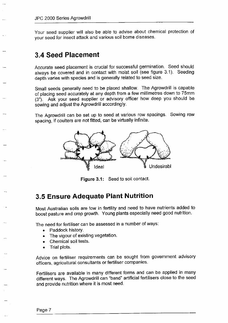
3.4 Seed Placement
Accurate seed placement is crucial for successful germination. Seed should always be covered and in contact with moist soil (see figure 3.1 ). Seeding depth varies with species and is generally related to seed size.
Small seeds generally need to be placed shallow. The Agrowdrill is capable of placing seed accurately at any depth from a few millimetres down to 75mm (3"). Ask your seed supplier or advisory officer how deep you should be sowing and adjust the Agrowdrill accordingly.
The Agrowdrill can be set up to seed at various row spacings. Sowing row spacing, if coulters are not fitted, can be virtually infinite.
Figure 3.1: Seed to soil contact.
3.5 Ensure Adequate Plant Nutrition
Most Australian soils are low in fertility and need to have nutrients added to boost pasture and crop growth. Young plants especially need good nutrition.
The need for fertiliser can be assessed in a number of ways: • Paddock history. • The vigour of existing vegetation. • Chemical soil tests. • Trial plots.
Advice on fertiliser requirements can be sought from government advisory officers, agricultural consultants or fertiliser companies.
Fertilisers are available in many different forms and can be applied in many different ways. The Agrowdrill can "band" artificial fertilisers close to the seed and provide nutrition where it is most need.
Page 7


JPC 2000 Series Agrowdrill
3.6 The Job's Not Finished at Seeding!
Careful preparation and seeding of a crop or pasture are only the first steps in the management process. There is a great deal of careful management practises needed after the Agrowdrill has given your seed the best chance of establishment.
3.6.1 Weed control
Effective weed control can be the difference between a profit and disaster. Good weed control before seeding will ensure emerging seedlings have a good start and an even better finish.
Certified seed, adequate fertility, correct seeding rates and placement of seed will put the odds in your favour for good germination and emergence.
The management practices after emergence however are just as important. Inspect your crop or pasture regularly for weed growth. If weeds become a problem you have a number of options open to you:
• Use a selective herbicide to kill weeds. • Strategic grazing or slashing can help reduce weed growth. • Applying fertiliser may help in some situations. • Cutting hay can remove weeds.
3.6.2 Insect Pest Control
Insect pests can seriously damage emerging or established crops and pastures. During your regular inspection you should also be on the lookout for insects. Consideration of the following points will help prevent or eliminate insects:
. • Grow species or varieties that are resistant to the common pests in your area.
• Use treated seed. • Spray only if absolutely necessary.
Note: Information on chemical control of weeds and insects should be available from government advisory officers, agricultural consultants, chemical resellers or spraying contractors.
3.6.3 Use of Fertiliser
Maintaining good nutrition is important for sustained production
All crops and pastures can benefit, in some situations, from additional fertiliser after seeding. Fertiliser can be added in many forms.
Page 8


JPC 2000 Series Agrowdrill
3.6.4 Grazing Management
New pastures can usually only stand light grazing in the first season. Perennial crops can also be grazed.
The following are some important points to remember: • Graze only when plants cannot be pulled out • Graze heavily for short periods to remove weeds. • Some species need to set seed each year, so allow this to take place. • Allow plenty of time for the pasture to recover after grazing.
Figure 3.2: The JPC 2000 Series Agrowdrill is designed for both direct drilling and traditional tillage practices
Page 9


JPC 2000 Series Agrowdrill
4.0 Hectaremeter Installation
The electronic Farmscan 1100 Hectaremeter is designed to fit virtually any farm tractor. It displays and records area sown and displays working speed (km/h).
Figure 4.1: Hectaremeter and Mounting Bracket
4.1 Installation Procedure
1. Mount the Hectaremeter in the tractor cab. Mount the control unit in a convenient location in the cab using the bracket and securing knobs supplied. The unit is not waterproof and therefore must be installed in a tractor cab. It must be protected against moisture. Warranty will not cover moisture damage.
2. Connect and secure the cable from the Hectaremeter to the shaft sensor.
The cable should be secured with cable ties along the A-frame, away from any risk of damage such as lubricants and moving parts. Dust caps should be plugged together when the cable is in use to ensure dust caps stay clean. Make sure dust caps are fitted when the cable is not being used.
Page 10


JPC 2000 Series Agrowdrill
3. Power Connection. Do not connect power until all other installation is complete.
The power cable must be connected DIRECTLY to the 12V DC vehicle battery terminals. DO NOT join power cable with any other electrical equipment or the vehicle chassis, as this may cause interference.
Use cable ties to secure power cable away from risk of damage.
Connection to battery terminals must be clean and tight.
Typical Batte,y Hook-Ups:
Two 12V Batteries One 12V Battery
Connection detail
Figure 4.2: Hectaremeter battery connection
Warning: Disconnect power cable from battery when arc welding on machinery as damage to the unit will result.
4.2 Hectaremeter Shaft Sensor Installation
The Agrowdrill comes with the Hectaremeter shaft sensor already installed. In the event of replacement or relocation the following points must be considered.
• The magnet, fitted to the shaft, must sweep past the sensor once per rotation with a clearance of 3-5mm. Do not use substitute magnets.
• Clamp the shaft magnet around a shaft or lock collar that is driven by a ground wheel. The clamp is adjustable from 19mm up to 38mm diameter. The magnet can be transferred to a larger clamp if required.
• The sensor and the magnet must face end to end.
Page 11


JPC 2000 Series Agrowdrill
• Do not remove the sensor from the aluminium bracket, as damage to the sensor will result.
Reed lype Sensor
Figure 4.3: Shaft Sensor Installation
• As the sensor is not affected by moisture or mud the main precaution is to protect the sensor and cable from physical damage. As a precaution keep the sensor cable away from aerial leads, engine kill switch cables or wires to electronic clutches and solenoid valves. Use the cable ties provided to secure the sensor cable.
Page 12

JPC 2000 Series Agrowdrill
5.0 Operating Instructions
5.1 Hitching and Levelling
The Agrowdrill should be matched to the tractor size to maximise performance and efficiency. A mismatched tractor and implement will be inefficient and cost money, as well as being unsafe.
5.1.1 Hitching
The hitching procedure is as follows:
1. Pin the tractor drawbar into the central position.
2. Attach the Agrowdrill to the drawbar and set the adjustable levelling tube so that the machine is approximately level.
Warning: Ensure the drawbar pin is locked into position so that it cannot work itself out when the machine is in operation or transit. Failure to do this may result in serious injury or death.
3. Attach the hydraulic coupling to your tractor remote outlet, taking care to clean away any dirt.
The working depth ofthe Agrowdrill is controlled by the hydraulic rams attached to the wheel assemblies. These are operated by the remote hydraulic system.
On some tractors it is necessary to set the hydraulic system to operate in the "single acting" or "bypass". Consult the tractor operator's manual.
4. Disengage the jack stand and adjust the hitch level to suit the drawbar height of the tractor. When level, ensure the levelling tube is locked using the locknut.
5.1.2 Hydraulic Lift Circuit
The procedure to connect and prime the hydraulic lift circuit is as follows:
1. Ensure both the tractor remotes and the hose couplings are clean and then connect to the tractor.
2. Loosen the hydraulic connector on the input line of the right hand wheel lift cylinder (see figure 5.1). This should be done to allow air to escape while the hydraulics are being primed.
Page 13

JPC 2000 Series Agrowdrill
·•·.· ..•. , ... •.·· .. ·· ........ .
. .
__ ,·,:(·•:
Figure 5.1: Right Hand Wheel Lift Cylinder
3. Slowly pressurise the hydraulics until oil appears at the loosened connection on the right hand cylinder.
Note: Stand well clear of the loosened connection as oil under pressure can spray wildly outwards. It is a good idea to place a hessian bag or similar material over the connection to minimise oil movement.
4. Retighten the connection as soon as oil appears.
5. Continue to prime the hydraulic lift circuit until the right hand cylinder is fully extended. Hold the hydraulics open for a further 15 to 20 seconds to allow air to clear from the circuit.
6. Fully raise and lower the machine several times to expel any residual air trapped in the circuit.
The lift circuit is now fully primed and the Agrowdrill can now be moved.
Page 14

JPC 2000 Series Agrowdrill
5.1.3 Levelling
The Agrowdrill must be level while operating. The levelling procedure is as follows:
1. Start working at the desired depth and observe the machine from both the side and the rear.
2. Adjust the levelling tube so that the machine is level from front to rear.
3. Retighten the locking collar on the levelling tube when adjustments are completed.
It is very important that the Agrowdrill be levelled correctly to achieve good results. As a final check, dig to the bottom of the furrow at two or three points across the working width of the machine and check the seeding depth. Ensure that the front and rear tynes are seeding at the same depth.
5.2 Tyre Pressures
Ensure that both tyres are inflated to a pressure between 250 - 285 kPa (35 -40 psi). A low tyre pressure on one side will cause an uneven seeding depth.
5.3 Seeding Depth
Seeding depth will vary depending on the species being sown. Generally speaking, small seeded species should be sown shallower. Larger seeded species will emerge if sown deeper.
The following are important guidelines:
• Seeding deeper than recommended will drastically reduce the chances of good germination and emergence.
• In hot, dry conditions the topsoil will tend to dry out rapidly and lead to poor germination.
• In wet, cool conditions the topsoil will remain moist and shallow placed seed will germinate effectively.
Consult a seed reseller or Advisory Officer for a recommendation regarding seeding depth if unsure.
Page 15

JPC 2000 Series Agrowdrill
5.4 Row Spacing
The row spacing of the Agrowdrill is infinitely variable. The only restriction will be the number of outlets on the hopper.
In some conditions it may be advantageous to seed in 127mm rows eg Irrigated Lucerne or Ryegrass. Other crops or pastures may require a wider spacing eg Sorghum at 350mm.
Consult a seed reseller or Advisory Officer for a recommendation regarding row spacing if unsure.
5.5 Operating Speed
The Agrowdrill will produce the best results if operated between 4 arid 8 km/h. Optimum speed will vary with the soil type, vegetative cover and root matter present.
Operating at higher speeds will increase soil surface disturbance, reduce penetration and seriously reduce the accuracy of seed and fertiliser placement. High speeds will also increase wear on the openers.
5.6 Hopper Selection
The metering system in all hoppers is identical meaning seed or fertiliser can be used in any hopper. In deciding which hopper to use it may be necessary to take into account and blending or banding options that may be used.
Model 20R 24R 28R 32R Bin 1 527 litres 612 litres 741 litres 827 litres Bin 2 479 litres 588 litres 675 litres 753 litres Bin 3 479 litres 588 litres 675 litres 753 litres Bin 4 527 litres 612 litres 741 litres 827 litres
Table 5.1: JPC 2000 Series Agrowdrill hopper capacities.
Page 16

JPC 2000 Series Agrowdrill
6.0 Calibration Instructions
6.1 Farmscan 1100 Hectaremeter
Before you can use your Agrowdrill the Hectaremeter must be calibrated and the metering rates must be checked for both seed and fertiliser.
Warning: If the Hectaremeter and metering system calibration is not carried out carefully then any data obtained will be unreliable.
The Hectaremeter must be calibrated to suit the width and distance the Agrowdrill travels per pulse from the shaft sensor.
The width and distance calibration factors are permanently stored in the memory whenever the 'CAL' routine is completed, as outlined below.
Important: If the calibration factors are corrupted due to outside interference, the readout will display 'HELP' to show that the calibration factors must be checked.
For ease of calibration both the width (Sowing Width) and Distance (Pulse Distance) calibration factors for a range of Agrowdrill configurations are supplied on section 6.10.
6.2 Operation of the Hectaremeter
Page 17
Not used in calibration
Up Key Down Key
m TOTAL ffi s [RE:ETJ ~
Calibration Key
Resets calibration figures to zero
Power ON/OFF
Figure 6.1: Farmscan 1100 Hectaremeter Calibration Keys
JPC 2000 Series Agrowdrill
ON/OFF KEY: The ON/OFF key turns the Hectaremeter power ON or OFF. Whenever the Hectaremeter is turned ON the TOTAL hectares will be displayed first. From this point you can select any other key
TRIP KEY: The TRIP key displays the trip Hectares and works just like the trip meter in your car. You can reset the TRIP Hectares for each paddock or load without losing the TOT AL Hectares.
Maximum trip reading is 999.9 Hectares. Resolution is 00.00 to 99.99 then 100.1 to 999.9 Hectares.
RESET KEY: Use the RESET key to set the TOTAL or TRIP Hectares back to zero. After selecting either TOTAL or TRIP Hectares, hold the RESET key down for approx. 3 seconds to clear the displayed figure back to zero.
SPEED KEY: The SPEED key displays the working speed (km/h) at any time whilst travelling.
MEMORY: Both the TOTAL and TRIP area readings are automatically stored in permanent memory - every 6 minutes of operation or when the unit is switched OFF using the ON/OFF key. The last 6 minutes of operating data will be lost if the power is interrupted at the source without first switching the unit of using the ON/OFF key.
FLASHING DECIMAL POINT: The decimal point on the display will flash for each pulse the meter receives from the shaft sensor to indicate that the unit is working. The sensor being mounted on the drive shaft enables the flashing decimal point to be interpreted that the drive shaft is engaged and turning.
6.3 Calibrating the Hectaremeter
Follow the steps below to enter the calibration factors.
1. Switch the Hectaremeter on.
2. Press the 'CAL' key to display H1 (The distance calibration factor) Eg. H1
0000
Page 18

JPC 2000 Series Agrowdrill
3. Use the up and down arrow keys to set the distance calibration factor to the Pulse Distance (in millimetres) as shown on the calibration chart for your model Agrowdrill.
Eg.2557
4. Press the 'CAL' key again to confirm the previous setting and display H2 (The width calibration factor)
5. Use the up and down keys to set the width calibration factor to the width (in metres) For standard configurations this distance can be obtained from section 6.10 or simply measure the distance from outside tyne to outside tyne and add one row spacing.
6. Press the 'CAL' key again to confirm the width setting, store them in memory and exit the calibration cycle. The Hectaremeter is now calibrated.
6.4 Metering Rates
Due to variations in seed sizes that can occur from crop to crop, season-toseason as well as normal variations between varieties, the gearbox and quadrant settings given on the calibration charts for seed and fertiliser should be used as a guide only. Cleanliness of samples will also effect actual rates, especially with oaten and some barley varieties.
For total accuracy it is recommended that you check the rate of flow from the metering system for each seed and fertiliser to be used. This will provide very accurate rates of seeding, and can be recorded for future reference. Blank charts have been pr9vided for you to record your own specific charts for future use.
6.5 Method for Checking Metering Rates
Our recommended static methods of checking metering rates use: • An accurate set of electronic scales (accurate to at least 2 grams) most
electronic kitchen scales will suffice. • A small amount of seed and/or fertiliser. • The use of five seeding rows to test each sample.
• Small containers to collect the seed and/or fertiliser.
If you do not wish to purchase a good set of electronic scales, it will be necessary to meter each sample through all hoses used across the machine and for a greater working distance. You must obtain a sufficient amount quantity for a reasonable degree of accuracy with conventional scales.
Page 19

JPC 2000 Series Agrowdrill
6.5.1 Calibration Procedure
1. Establish the working width of your drill. 1.1 Measure the row spacing in metres. 1.2 Multiply this figure by the number of rows on your machine.
2. Determine the rolling circumference of your drive wheel. 2.1 Ensure the tyre is inflated to recommended pressure. 2.2 Lift the machine into transport position. 2.3 Mark the tyre at contact point with the ground. 2.4 Place a peg or marker at this same location. 2.5 Tow the machine for x number of wheel revolutions. (The greater
the number of revolutions used the more accurate the calculation.) 2.6 Measure the distance travelled (in metres) and divide by x to obtain
the rolling circumference.
3. Calculate the number of wheel revolutions per Hectare. 3.1 Using the information obtained in steps 1 & 2 above use the
following formula
3.2 10000
Wheel Revs/Ha=--------Wheel Circ. x Working Width
4. Calculate idle shaft revolutions per Hectare. 4.1 This calculation is simply the Wheel Revs/Ha (see 3.2) multiplied
by the idle shaft ratio for your drill. The ratio for the JPC 2000 Series Agrowdrill is as follows:
Idle Shaft Ratio = 1.96
5. Distance to travel a Hectare.
5.1 10000
Distance to travel Ha = ----Working width
6. Hectare meter settings.
6.1
6.2
Wheel Circumference H1 - Pulse Distance=------
Idle Shaft Ratio
H2 - Working Width (see 1 above)
For Example:
An 20 Run Drill with 24 tynes at 178mm spacing.
From (1) the working width = =
24x0.178 4.272m
From (2) the wheel circumference is 5.01m
Page20

JPC 2000 Series Agrowdrill
Therefore using the formula in (3.2):
Wheel Revs / Ha :a :;:
Therefore using equation (4.1) Idle shaft revs :a
=
Using equation (5.1 ): Distance to travel Ha =
=
To calibrate your drill:
10000 I (5.01 X 4.272) 467.23
467.23 X 1.96 915.77
10000 / 4.272m 2340.Bm
1. Set the quadrant lever on the approximate setting indicated from the rate charts.
2. Position containers to collect from a number of hoses. (The more hoses used the more accurate your calibration. Usually 5 hoses are adequate.)
3. Turn the crank handle the equivalent of a Ha, 467.23 revs, or a fraction thereof. (It follows that the closer to Ha you use the more accurate your calibration) In general figures 1150th of a Ha has proven adequate. For the above this would be 1150th of 467 .23 = 18.25 revs.
4. Collect the material from the containers and weigh this. Say 417 grams was collected.
5. Unless you collected from all 24 hoses and turned the crank handle· 915.77 turns, you will need to amend the weight collected as follows:
kg/Ha= ( ( Number of Rows on Drill) )
Weight of seed collected x --------- x Fraction of Ha Number of Rows Collected
1000
It should be noted that by collecting seed from five (5) hoses and cranking the equivalent of 1 / 50th of a Ha, the above formula will simplify to:
kg/ Ha = = =
Weight Collected x Number of rows on Drill / 100 417 X 24 /100 100 kg/ Ha
Alter the gearbox quadrant setting up or down as required and repeat the procedure until the desired seeding rate is required.
6.6 Field Calibration
The following procedure can be used to determine the precise application rate during the seeding operation:
1. Fill the hopper to the top and level the seed and fertiliser.
Page 21

JPC 2000 Series Agrowdrill
2. Set the trip meter on the Hectaremeter. 3. Commence seeding and work until the hoppers are more than half
empty. 4. Refill the hoppers taking careful note of the amount added in kilograms. 5. Note the number of hectares indicated. 6. Calculate the actual sowing rate using the following formula:
Kg/ Ha = Kg of seed or fertiliser used / Hectares sown
7. Readjust rates as necessary.
6. 7 Plotting Calibration Charts
This procedure will allow for the plotting of calibration charts for seeds or fertilisers not listed or for the modification of existing charts.
1. Set the varibox adjusting lever to the maximum setting and carry out the calibration procedure as outlined in the section above.
2. Select a blank chart (or draw a new one) suitable to the seeding rate achieved.
3. Find the point on the x-axis (bottom) that corresponds to the achieved seeding rate.
4. Mark a point on the maximum quadrant setting line that corresponds to the achieved seeding rate.
5. Draw a straight line from this point to the bottom left hand corner (0,0).
This line indicates the approximate amount of seed or fertiliser rate at any given quadrant setting.
6.8 Adjusting the Seed and Fertiliser Rates
Adjusting the seed and fertiliser rates on the Agrowdrill is very simple as it only involves three components:
• Gearbox. • Restrictors applied to the fluted rollers. • Adjustable gates under the fluted rollers.
All three may need to be adjusted.
6.8.1 Gearbox Adjustments
The Agrowdrills unique gearbox allows adjustments of seed and fertiliser rates over a wide range by simply adjusting one lever for each.
The levers are located on the bottom of the hopper in the centre of the machine. The lever closest to the front of the machine adjusts the front hopper.
Page22
JPC 2000 Series Agrowdrill
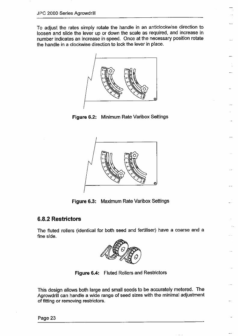
To adjust the rates simply rotate the handle in an anticlockwise direction to loosen and slide the lever up or down the scale as required, and increase in number indicates an increase in speed. Once at the necessary position rotate the handle in a clockwise direction to lock the lever in place.
0
Figure 6.2: Minimum Rate Varibox Settings
0
Figure 6.3: Maximum Rate Varibox Settings
6.8.2 Restrictors
The fluted rollers (identical for both seed and fertiliser) have a coarse and a fine side.
Figure 6.4: Fluted Rollers and Restrictors
This design allows both large and small seeds to be accurately metered. The Agrowdrill can handle a wide range of seed sizes with the minimal adjustment of fitting or removing restrictors.
Page23

JPC 2000 Series Agrowdrill
Recommended Restrictor and Gate Settings:
Seed Gate Setting Restrictors Fitted Lupins 3 No Oats 3 No
Wheat 2 2 of4 Canela 0.75 3 of4
Sub Clover 1 3 of4 Lucerne 1 3 of4
Single Super 2 No OAP 1.5 No Urea 1.5 No
To reposition Restrictors:
1. Grasp the rear arm of the restrictor and gently twist the arm sideways to release it from under the adjustable stopper and remove
2. Reinsert the restrictor into the new position or leave out as required.
6.8.3 Gate Settings
The gate adjustment levers are located on the right hand end of the Agrowdrill, the front lever adjusting the front hopper. In most circumstances you will not need to adjust the gate settings. The gates may need to be opened to meter very large seeds.
Adjust as follows:
1. Check the gate setting recommendation for the seed or fertiliser being used (refer to the above table).
2. Loosen the Knob (rotate in an anticlockwise direction) slide the lever up or down the scale as required. Once at the necessary position lock the lever in place (rotate the knob in a clockwise direction).
6.9 Calibration Charts
The following charts are intended as guide only. They are based on a standard row spacing of 175mm and do not take into account variety changes or cleanliness of the sample.
Correctly calibrating the Agrowdrill at each change of seed, fertiliser or application rate will prevent any undesired metering rates. The calibration procedure is outlined in section 6.5.
Page24

JPC 2000 Series Agrowdrill
-WHEAT -
----
8
7
6
5
4
3
2
1
0
-------:--. . . . . • • • • • T
--------• • • • • •
0 25 50 75 100 125 150 175 200 225 250
RESTRICTORS 2 of 4 I GATE SETTING 2
8
7
6
5
4
3
2
1
0
/ /
/. . . . ' ' ' • '
0 20 40
NO RESTRICTORS / GATE SETTING 3
Page 25
Sowing Rate in kg / Ha @ 175mm (7") row spacing
- OATS -
/
. . • '
60
/
/ /
./
. . . . • • ' T • ' ' '
80 100 120 Sowing Rate in kg / Ha
@ 175mm (7") row spacing
. '
140
• •
160

8
7
6
5
4
3
2
1
0 0
. . I I
20 40
NO RESTRICTORS / GA TE SETTING 3
JPC 2000 Series Agrowdrill
- LUPINS -
• . . I
60 80
---. . . I I I
100 120 140
Sowing Rate in kg / Ha @ 175mm (7") row spacing
180
- RYEGRASS -7
6
5
4
3
2
1
0
0 2 4
RESTRICTORS 2 of 4 / GA TE SEmNG 1
6 8 10 12 14 16 18 20 Sowing Rate in kg / Ha
@ 175mm (7") row spacing
Page26

JPC 2000 Series Agrowdrill
7
6
5
4
3
2
1
0
0 2 4
RESTRICTORS 3 of 4 / GATE SETTING 1
-LUCERNE-
6 8 10 12 14 16 18 20 Sowing Rate in kg / Ha
@ 175mm (7") row spacing
- SUB CLOVER -7
6
5
4
3
2
1
0
0 2 4
RESTRICTORS 3 of 4 / GATE SETTING 1
Page27
6 8 10 12 14 16 18 20 Sowing Rate in kg / Ha
@ 175mm (7") row spacing

7
6
5
4
3
2
1
0
0 3 5
JPC 2000 Series Agrowdrill
- CANOLA -
7 9 11 13 15 17 19
RESTRICTORS 3 of 4 / GATE SETTING 0,75
Sowing Rate in kg / Ha @ 175mm (7") row spacing
8
7
6
5
4
3
2
1
0
- SINGLE SUPER -...
/"
/ /
/
/ ' . . . . . . . . .
' . ' ' ' ' ' . ' ' I
0 25 50 75 100 125 150 175 200 225 250 275 300
NO RESTRICTORS /GATE SETTING 2
Sowing Rate in kg / Ha @ 175mm (7") row spacing
Page28

JPC 2000 Series Agrowdrill
- D.A.P. (High Analysis Only) -8
7
6
5
4
3
2
1
0 0
/ •
/ . . . I I •
50 100
NO RESTRICTORS / GATE SETTING 1.5
8
7
6
5
4
3
2
1
0 /.
•
/ .
-,
_/
. . -, •
_/
,/ ,/
_/
• . . . . . . . • I I I I I
150 200 250 Sowing Rate in kg / Ha
@ 175mm (7") row spacing
- UREA --
/ /
/ /
• . • . . . • • • I I I
0 50 100 150 200 250
NO RESTRICTORS /GATE SETTING1 .5
Page 29
Sowing Rate in kg / Ha @ 175mm (7") row spacing
,/
. I
300
. I
300

8
7
6
5
4
3
2
1
0
8
7
6
5
4
3
2
1
0
-
. ' --, •
0 20 40
RESTRICTORS / GATE SETTING
-
. ' -, •
0 20 40
RESTRICTORS /GATE SETTING
JPC 2000 Series Agrowdrill
. . . • --, '
60 80 100 Sowing Rate in kg / Ha
@ 175mm (7") row spacing
' . .
• I •
60 80 100 Sowing Rate in kg / Ha
@ 175mm (7") row spacing
-
• ' ' '
120 140 180
-
' .
' ' 120 140 180
Page30

JPC 2000 Series Agrowdrill
No Restrictors One Restrictor
Two Restrictors Three Restrictors
Figure 6.5: Restrictor Positioning
Page 31

"U Ill cc (D
c,., N
6.10 Agrowdrill Calibration Settings
The following table provides a guide to the correct calibration factors for the JPC 2000 Agrowdrill. For accuracy it is recommended that the procedure outlined in Section 6.5.1 be followed for calibration.
These settings are for the standard row spacing only and are based on an 18.4 x 34 tyre size.
Machine Size No. of
Rows
Row Spc. I Sowing mm Width
Wheel I idle shaft I distance to I FarmScan I Kee Rev/Ha. Rev/Ha. travel Ha. Pulse Dist. Clrc. Dist.
No.
Hoses No. I Multiply By
Turns kg/ Ha
c.... "U 0 N 0 0 0 (/) (D ::::!. (D C/)
;g
i ::::!.

JPC 2000 Series Agrowdrill
7.0 Operating Tips
7 .1 After the First Round
The following is a list of points that should be checked after the first pass or round of a paddock:
1. Ensure both the seed and fertiliser drives are rotating. Note: Problems in this area can be avoided with adequate maintenance and checking the rotation of the drives before commencing.
2. Check that the seed and fertiliser are running evenly through all rows. 3. Ensure that the bottoms of the delivery tubes are not blocking up with
wet soil. If this occurs the soil should be allowed to dry before continuing.
4. Check the soil openers for any loose bolts. 5. Check the machine for any loose bolts. 6. Retension all tyne clamps.
7 .2 Gradual Slowing of Fertiliser Flow
This often happens when using fertilisers such as single super that have a high percentage of fine powder. The powder generally builds up at the bottom of the fertiliser hopper and slows the flow rate. This may also occur with limecoated seeds, as the lime is prone to flaking off.
To avoid this problem, occasionally run the fertiliser hopper to a low level and clear away any powder build up manually by opening the gate settings to the widest setting. Only do this while the machine is stationary.
7 .3 Seizing of the Metering System
This can easily happen when using highly soluble and corrosive fertilisers such as urea. Such fertilisers will 'cake' rapidly in moist conditions and may seize the fluted rollers.
This can be avoided by never leaving the Agrowdrill filled with fertiliser or seed in moist conditions.
Page 33

JPC 2000 Series Agrowdrill
7 .4 Checking the Rotation of the Drives
The rotation of the seed and fertiliser metering mechanism can be easily checked by 'ratcheting' the Varibox adjustment levers. Simply loosen the knurled knobs and move the lever backwards and forwards a number of times. This will rotate the drives allowing the following to be done:
• Check if the metering system is seized with 'caked' fertiliser. • Free small blockages caused by 'caked' fertiliser. If the 'caking' is
severe the hopper may need to be cleaned out manually. • Check for blockages in the fluted rollers, delivery tubes or soil openers. • The quantity of seed and fertiliser under each opener should be
observed to ensure equal metering of seed and fertiliser across the width of the machine.
7 .5 Cleaning Seed and Fertiliser Hoppers
Thorough cleaning of the seed and fertiliser hopper is very important for a number of reasons including:
• Fertiliser left in the hopper will cause corrosion of the metal parts of the Agrowdrill.
• If you are changing to a different seed all the previous seed must be removed to prevent contamination.
• Seed left in the Agrowdrill will attract mice, rats and insects.
The following is the procedure for cleaning: 1. Try to have as little seed or fertiliser as possible remaining after
finishing the seeding. 2. Scrape all the remaining seed or fertiliser to one side and scoop into
bags or buckets. Sweep the bottoms of the hoppers clean with a broom.
3. Remove all restrictors and open the gates under the fluted rollers. For end of season cleaning remove verandahs to allow easier cleaning.
4. Use an air compressor or water hose to blow or wash out any remaining seed or fertiliser. A vacuum cleaner used to suck out remaining seed or fertiliser also works well.
5. Close the gates under the fluted rollers and reinstall the restrictors into the desired location. Replace the verandahs.
6. Clean away any seed or fertiliser that may have spilled onto the frame of the Ag rowd rill.
Note: If the Agrowdrill is washed with water allow the hoppers to dry out thoroughly by placing the Agrowdrill in the sun with the hopper lids open.
When the Agrowdrill is clean and dry, apply a light coating of diesel to the insides of the hoppers to prevent any corrosion from fertiliser.
Page 34

JPC 2000 Series Agrowdrill
8.0 Lubrication and Maintenance
The Agrowdrill is an extremely robust and durable machine and will give many years of service with simple routine maintenance.
8.1 Pre-Operation Check
Check the following points before operation:
• Check all nuts and bolts are tight. • Check tyne spacings are correct. • Check all sowing hoses and tubes are unblocked and correctly
positioned. • Check all grub screws are tight. • Check metering shafts are easily turned using the crank handle
provided. The shafts should not be jammed or hard to turn. • Check the Hectaremeter is installed correctly and functioning properly.
8.2 Daily Service
Before starting work each day the Agrowdrill should be carefully checked for the following:
• Loose soil opener mounting bolts. Tighten as necessary. • Excessively worn soil openers. Replace as necessary. • Bent or blocked down tubes. In rough or stony conditions down tube
mounting brackets may bend. Straighten if possible or replace. • Quick visual check of entire machine.
8.3 Lubrication
The lubrication schedule for the Agrowdrill is as follows:
Item Action Interval Drive Chains Apply Oil 20 Working Hours
Wheel Axle Bearings Grease 100 Working Hours Chains Wash and Grease 200 Working Hours Varibox Check Oil 200 Working Hours Varibox Change Oil 3 Years
Page 35
JPC 2000 Series Agrowdrill
8.4 Replacing Soil Openers
You should replace soil openers when they wear past the tungsten tip or lose their point. Blunt tips or worn heels will reduce the digging efficiency and seed placement accuracy of the Agrowdrill.
The procedure for changing soil openers is as follows:
1. Place the Agrowdrill on a hard surface and lift to the highest position and secure using the ram safety stoppers.
2. Turn the tractor off. 3. Remove retaining bolts that attach the opener to the shank. Depending
on the type of opener there may be one or two bolts. 4. Remove worn opener and any damaged bolts. 5. Install new openers and any bolts and tighten bolts firmly.
8.5 Downtube Assembly
Use the following procedure to service the down tube assembly:
1. Remove the rubber boot from the retaining lugs on the fluted roller housing.
2. Twist the bottom of the flexible tube off the seeding boot and remove the downtube assembly.
3. Screw out the flexible tube. 4. Replace the rubber boot or flexible tube as required. Ensure the new
flexible hose is of similar length.
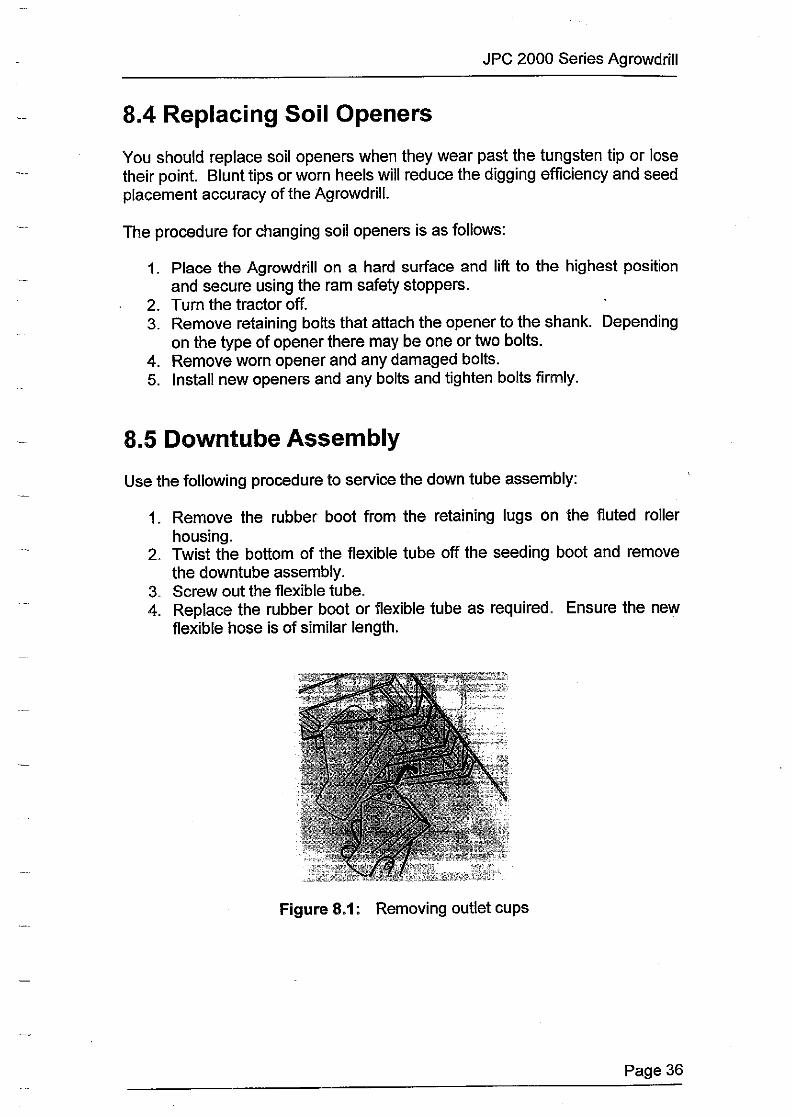
Figure 8.1: Removing outlet cups
Page 36

JPC 2000 Series Agrowdrill
8.6 Replacing Adjustable Gates
The adjustable gates are controlled by a hexagonal rod connected to the adjustment lever. Use the following procedure to replace worn or broken gates:
1. Remove the drive chain cover plate from the left side of the hopper. 2. Loosen the bolt that retains the gate adjustment lever. 3. Slide the hexagonal shaft out and remove worn or broken gates as
required. 4. Slide the shaft back in assembling and replacing the gates as
necessary. 5. Tighten the bolt that retains the gate adjustment lever. 6. Replace the drive chain cover plate.
8. 7 Servicing the Fluted Rollers
The fluted rollers are driven by hexagonal shafts through the drive chains and sprockets on the left side of the Agrowdrill. These shafts are supported by self-aligning ball bearings adjacent to the sprockets and by glass filled nylon bushes mounted between every third outlet.
Servicing procedures are as follows:
8. 7 .1 Drive Sprocket Bearings
1. Remove the drive chain cover. 2. Remove the drive chain. 3. Remove the grub screws that retain the drive sprocket and slide the
sprocket off the end of the shaft. 4. Loosen the grub screw retaining the bearing locking collar and rotate
the collar to release the bearing. 5. Remove the two retaining bolts from the bearing housing and slide the
bearing off the end of the shaft. 6. Replace the bearing and reinstall, reversing the above procedure.
8.7.2 Fluted Rollers
1. Remove the drive chain cover and drive chain. 2. Remove the two mounting bolts from the self-aligning bearing. 3. Pull the drive shaft out. In most cases it won't be necessary to remove
the shaft completely. Only slide the hexagonal shaft far enough to reach the worn or damaged rollers.
4. Replace rollers as necessary and reverse the above procedure to reassemble.
Page 37

JPC 2000 Series Agrowdrill
8.7.3 Drive Shaft Mounting Bushes
The Agrowdrill is fitted with glass filled nylon bushes between every third row. These bushes require no lubrication, are extremely wear resistant and should last the life of the machine.
Use the following procedure if service is needed:
1. Remove the fluted roller shaft as outlined in the above section. 2. Remove the retaining bolt from the worn or damaged bush and replace
the bush. 3. Reinstall the drive shaft.
Figure 8.2: Drive shaft mounting bushes
8.8 Major Servicing of the Metering Mechanism
In the event of the metering mechanism requiring major servicing the bottom of the hoppers can be completely removed.
1. Remove the down tube assemblies and fluted roller drive sprockets and bearing assembly as outlined in previous sections.
2. Remove all restrictors.
Figure 8.3: Removing and installing restrictors
Page 38
JPC 2000 Series Agrowdrill
3. Remove the retaining bolt from the front and rear of each fluted roller assembly and lower the entire metering mechanism from the bottom of the hoppers.
4. Installation procedure is the reverse of the above. The ends of the metering assembly will need to be resealed with a quality silicone sealant.
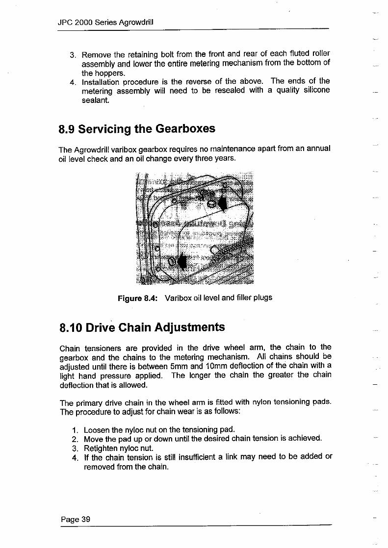
8.9 Servicing the Gearboxes
The Agrowdrill varibox gearbox requires no maintenance apart from an annual oil level check and an oil change every three years.
Figure 8.4: Varibox oil level and filler plugs
8.10 Drive Chain Adjustments
Chain tensioners are provided in the drive wheel arm, the chain to the gearbox and the chains to the metering mechanism. All chains should be adjusted until there is between 5mm and 10mm deflection of the chain with a light hand pressure applied. The longer the chain the greater the chain deflection that is allowed.
The primary drive chain in the wheel arm is fitted with nylon tensioning pads. The procedure to adjust for chain wear is as follows:
1. Loosen the nyloc nut on the tensioning pad. 2. Move the pad up or down until the desired chain tension is achieved. 3. Retighten nyloc nut. 4. If the chain tension is still insufficient a link may need to be added or
removed from the chain.
Page 39

JPC 2000 Series Agrowdrill
8.11 Drive Chain Maintenance
The drive chains will benefit from some form of lubrication. The two recommended methods are:
• Oil chains regularly during seeding using a quality chain oil. • Remove the drive chains annually and store them in a pot of quality
chain oil.
Note: The most crucial measure to ensure long chain life is to avoid leaving the Agrowdrill exposed to the weather between seeding jobs.
8.12 Hectaremeter Sensor and Cable
Check the function of the Hectaremeter sensor and cable by the following procedure:
1. Switch the Hectaremeter on. 2. Check that the H1 and H2 calibration factors are entered correctly. 3. Press SPEED key. Display should read 0.0. 4. Disconnect sensor from cable, at the sensor itself. 5. Use a pair of long nose pliers and intermittently short the pins of the
connecting plug on the cable together. The speed readout should show random numbers. If the speed readout responds, reconnect sensor.
6. If no response, reconnect sensor and repeat test at tractor breakaway plug (if used). If at this point the speed responds, then the cable between the breakaway plug and the sensor is faulty and will need replacing.
7. If still no response at the tractor breakaway plug repeat the test directly into the Hectaremeter unit itself.
8. If no response is registered at this point return the Hectaremeter unit to the nearest Farmscan dealer or authorised service agent.
8.13 Hectaremeter Multimeter Test
8.13.1 Reed Type Sensor
If the Hectaremeter is malfunctioning the reed type sensor can be checked using the following procedure:
1. Disconnect cable from sensor. 2. Rotate the shaft so that the magnet is as close as possible to the
sensor. 3. Measure the resistance of the sensor using a multimeter. It should be
a short circuit (ie the multimeter shows infinity).
Page40

JPC 2000 Series Agrowdrill
4. Rotate the shaft so that the magnet is as far away as possible from the sensor.
5. Measure the resistance of the sensor using a multimeter. It should be an open circuit (ie the multimeter shows zero).
8.13.2 Sensor Cable
Check the function of the sensor cable using the following procedure:
1. Disconnect Hectaremeter and Sensor from sensor cable. 2. Place a sturdy wire link across the two terminals at the Hectaremeter
end of the cable. 3. Measure the resistance across the two terminals at the sensor end
using a multimeter. It should be a short circuit. 4. If it is short circuit, check that any breakaway connections are clean
and connect firmly. If loose use a small object to close the female connection slightly.
5. Physically inspect cable for damage as it may have been crushed or cut.
8.14 End of Season Storage
To ensure a long and trouble free working life please take the following steps when storing the Agrowdrill for long periods.
• Clean out the hoppers thoroughly according to the procedure outlined in section 7.5.
• Shed the Agrowdrill for protection against the weather. • Ensure chains are properly oiled and covered before storage or remove
chains and store them in an oil bath. • Ensure all grease nipples are thoroughly greased before storage. By
excluding air and moisture from inside the bearings the chance of corrosion will be minimised. For best results grease the bearings while they are still warm from the last working.
Page 41
SIMPLE ROUTINE MAINTENANCE WILL
PROLONG THE LIFE OF THE JPC 2000 SERIES
AGROWDRILL

7J ~ (1)
.;,. N
9.0 Trouble Shooting Guide
9.1 Underframe
The Problem Possible Cause
Soil is too dry
Poor penetration Insufficient weight • Machine not level
Soil is too dry
Working too deep • High soil opener wear
Highly abrasive soil
Machine not level
The soil is too dry and hard
Tynes 'laying back' Machine not level
Working too fast
Possible Solution
• Wait for rain or irrigate
• Keep hoppers full Fill tyres with water to add weight
• Adjust levelling tube to suit
• Wait for rain or irrigate
Raise Agrowdrill to shallower depth
• Use tungsten tipped points
• Adjust levelling tube to suit
• Wait for rain or irrigate
• Adjust levelling tube to suit
• Slow to a suitable speed
c.. 7J (')
N 0 0 0 (I) (1) ::::!. (1) (/l
:g
i ::::!.

""Cl Dl :0 CD _.,. t,J
I
The Problem
Too much surface disturbance
Too deep on one side
Machine blocking up with trash
Blocked downtubes or seeding boots
Possible Cause
Not working deep enough
Working too fast
Incorrect depth setting
Low depth wheel pressure on one side •
Low tractor tyre pressure •
Too much trash
Wet Conditions
Tynes too close
Misalignment of tynes
• Mud build up •
Insect or rodent nests •
Kinked downtube •
Possible Solution
• Adjust deeper
• Slow to a suitable speed
• Adjust depth stoppers evenly
Inflate to recommended pressures
Inflate as recommended in tractor manual
• Graze heavily before seeding
• Slash paddock
• Control weeds before seeding
• Allow soil and trash to dry
• Adjust spacing to wider setting
• Adjust tyne spacing to correct alignment
Rec lace anv bent or twisted tvnes Clean blockage and wait for drier
conditions
• Remove downtube and clean Prevent mice or insect infestations
• Repair or replace Avoid conditions where tubes may be
damaaed
c.... ""Cl ()
N 0 0 0 (/) CD :J.
ffi :g
i :3.:

"tl Ill :0 (1)
.i:.
.i:.
9.2 Metering System
The Problem
Falling fertiliser rate
Incorrect metering rates
Some rows not metering
Some rows metering too quickly
Self feeding seed or fertiliser
Possible Cause
Powder build up in hopper
Caking
Different seed or fertiliser than that used to calibrate the Agrowdrill
Blocked roller
Stripped roller
Fertiliser clods in hopper
Restrictor cap missing
Broken adjustable gate
Gate settings too wide
Restrictor caps not in place
Damaged gate
•
•
•
•
•
• •
•
•
•
•
Possible Solution
See 'Operating Tips' section
See 'Operating Tips' section
Recalibrate
Clean out hopper and unblock
Replace roller
Clear blockages
Clean out hoppers and check location of restrictors
Replace gate
Close up gate setting
Clean out hopper and check location of restrictor caps
Replace gate
c.... "tl (") I\) 0 0 0 (/) (1) ~
ar u,
:g
i 2:

7J
c2l CD .i,,. 0,
The Problem
Failure to meter seed or fertiliser
-
Broken Chain
Notes:
Possible Cause
Sprockets loose on shaft
Gearbox broken
Chain dismounted
Broken drive chains
Chain misalignment
Worn chain
Incorrect chain tension
Seized shafts
•
•
•
•
•
•
•
• • • •
Possible Solution
Tighten or replace grub screw on sprockets
Replace gearbox
Check alignment
Check condition of chain
Replace chain
Realign chain
Replace chain
Retension chain
Grease bearings Clean metering system Remove spilled fertiliser
c.... 7J 0 N 0 0 0
en CD ::::l. CD
"' t i ::::l.
I

1J Dl :c CD
~
9.3 Hydraulics
The Problem
Uneven lift
Poor lift response
Notes:
Possible Caus~
Hydraulics not primed
Air in hydraulic hose
Low oil level in tractor
- I
Possible Solution
• Prime hydraulic system
• Bleed air from system
9 Add oil according to tractor operation manual
t.. 1J 0 I\) 0 0 0 Cl) CD ~
cii' (/)
l;'
i ~

7J g 9.4 Hectaremeter .j>. ---.I
The Problem
No response from ON/OFF switch
Hectaremeter total wrong
Decimal point will not flash
Hectare or Speed does not work
Trip or Total Hectares fail to reset
• •
•
• • • •
• • • • • • • • • • • • • •
Probable Cause / Remedy
Check that power cable connections at battery are clean and tight Measure voltage from power cable at monitor connection point. It should be between 12-13.8 V DC If voltage ok and unit fails, return to nearest Farmscan dealer or authorised service aaent. Check that calibration factors H 1 and H2 are correct Is the machine overlapping or underlapping? Is the unit counting headlands? Switch to SPEED readout and make sure it is reading at a constant speed. Cable or sensor could be damaged if readout is jumpy. Is the magnet facing the sensor end to end? Is the correct magnet being used? Is the magnet too far away from the sensor? (3-5mm gap) Is the magnet staying in line with the sensor on corners? Is the wheel loose? Is the sensor on a non-driven wheel? Tractor drive wheels will cause an over reading . Reolace wheel / shaft sensor if none of the above . This is normal if TOTAL hectares are above 999.9, or it is extremely cold . Speed must be above 2.0km/h to register . Check that the calibration factors H1 and H2 are correct. Check that maanet and sensor are correct with correct aao /3-5mml Press TOTAL or TRIP key first to select area to be cleared . RESET key must be pressed and held down for at least 3-4 seconds If hectares still fail to reset, return unit to nearest Farmscan dealer or authorised service aaent.
c.... 7J (")
N 0 0 0 Cl) <D ::l. <D en
:g
i ::l.

·1
"U DI :c CD J>. CX)
I . · 1
The Problem
Hectares count up on their own without moving
or
Calibration figures keep changing
Notes:
•
•
•
•
•
- I
Probable Cause/ Remedy
Switch off all other electronics to eliminate electrical interference as the cause .
If switching off electronic eliminates the fault, ensure the Hectaremeter cables are not running alongside wiring from other electrical devices, and / or physically move the Hectaremeter in relation to the other equipment.
If petrol engine in close proximity, stop the engine to see if interference is caused by ignition system . Note: Carbon ignition leads must be fitted to spark plugs and coil to stop interference.
Disconnect Sensor from cable at wheel I shaft. If the problem stops, replace the sensor. Make sure the Hectaremeter has an independent power cable, wired directly to the battery + and - terminals . If unit still counts hectares, return unit to nearest Farmscan dealer or authorised service aaent.
c... "U () I\) 0 0 0
r:n CD :::!. CD
"' :6' i 2.:
-~


