36
HL-LHC Planned Activities - Accelerator I. Bejar Alonso – HL-LHC Technical coordinator On behalf of HL-LHC WPs Leaders
| Date post: | 19-Dec-2015 |
| Category: |
Documents |
| Upload: | anna-townsend |
| View: | 219 times |
| Download: | 0 times |
HL-LHC Planned Activities - Accelerator
I. Bejar Alonso – HL-LHC Technical coordinator
On behalf of HL-LHC WPs Leaders
Click here to add footer 2
HL-LHC BASELINE (P. FESSIA PRESENTATION)

Click here to add footer 3
Equipment on the Beam Tunnel equipment Vert. J Surface Eq. Dis.
DF(X-M) + SC Link DSH (X-M)
Cryo line IR+MSAlignment
QPS2
Magnet systemMQXFA MQXFB, MBXF, MBRD, MQYY,
Q5 1.9, Q6 1.9MCBXFB, MCBXFA, MQSXF, MCTXF, MCTSXF,
MCDXF, MCDSXF, MCOXF, MCOSXF, MCSXF,MCSSXF,MCBRD, MCBYY
Beam vacuum
TAXS, TAXN
Interaction Region and MS IP 1,5
Collimation (TCTPM, TCL, TCLM, TCTP)
Beam diagnosticBPMSQW, BMPSQ, BPMSQT, BMLC
DS Collimation for ion IP 2
H.F. dipoles
Cryo-bypass+TCLD
DFH(X-M) + Power converters
SC link/powering IP 7
Hor. SC Link DSH + DFA
Power converters
EE
Crab Cavity cryomodules
RF systemLoads, circulators, RF power, LLRF, HVPS,
central LLRR
DS Collimation pp (TBC RUN II) IP 1,5
H.F. dipoles
Cryo-bypass+TCLD
DS Collimation pp (TBC RUN II) IP 7
H.F. dipoles
Cryo-bypass+TCLD
Rad-hard electronics for BLM and BPM
CC diagnostic and protection
PIC
BIS
DFA+ SC Link DSHA
DFHA + Power converters
SC link/Powering
arcIP 1,5
Cryoplant IP 1,5
CB Warm compressor and other surface eq.
In orange Works
during LS2
Click here to add footer 4
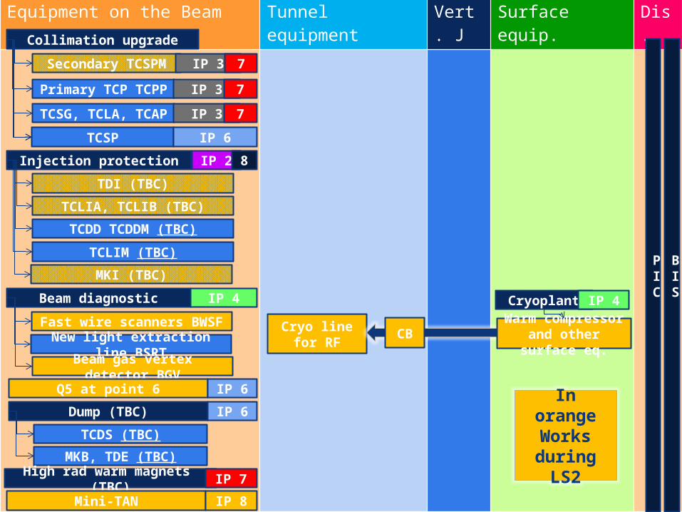
Equipment on the Beam Tunnel equipment Vert. J Surface equip. Dis.
Cryo line for RF
Beam diagnostic IP 4
Fast wire scanners BWSF
New light extraction line BSRT
Beam gas vertex detector BGV
Injection protection IP 2 8
TDI (TBC)
TCLIA, TCLIB (TBC)
TCDD TCDDM (TBC)
TCLIM (TBC)
MKI (TBC)
Q5 at point 6 IP 6
Dump (TBC) IP 6
TCDS (TBC)
MKB, TDE (TBC)
PIC
BIS
High rad warm magnets (TBC) IP 7
Collimation upgrade
Secondary TCSPM
Primary TCP TCPP
TCSG, TCLA, TCAP
IP 3 7
IP 3 7
IP 3 7
TCSP IP 6
Mini-TAN IP 8
CB
Cryoplant IP 4
Warm compressor and other surface eq.
In orange Works during
LS2
Click here to add footer 5
HL-LHC OPTIONS
Click here to add footer 6
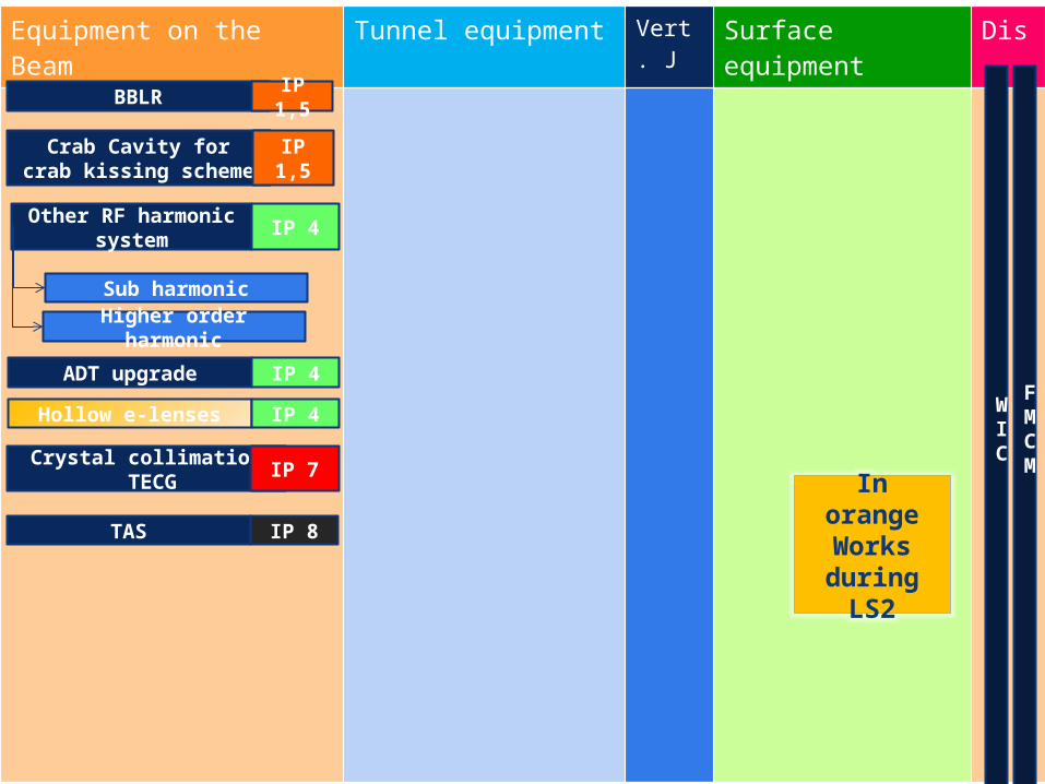
Equipment on the Beam Tunnel equipment Vert. J Surface equipment Dis.
WIC
FMCM
Other RF harmonic system
IP 4
Sub harmonic
Higher order harmonic
ADT upgrade IP 4
Crystal collimation TECG
IP 7
BBLR IP 1,5
TAS IP 8
Hollow e-lenses IP 4
Crab Cavity for crab kissing scheme
IP 1,5
In orange Works during
LS2
Click here to add footer 7
HL-LHC ARCHITECTURE & INSTALLATION DURING LS2
Click here to add footer 8
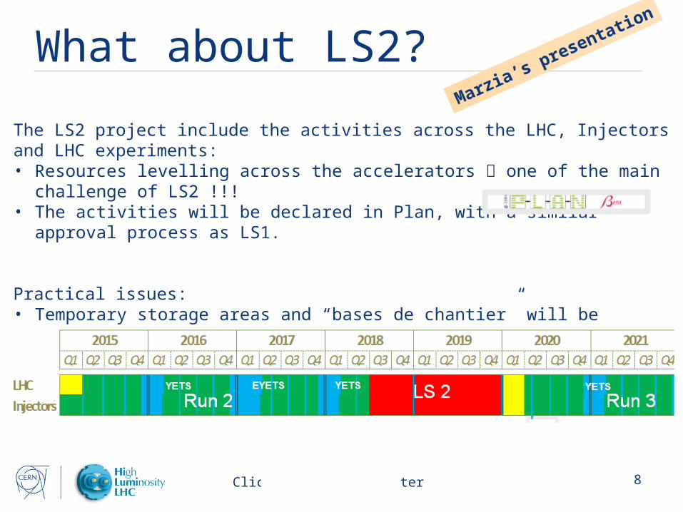
What about LS2?
The LS2 project include the activities across the LHC, Injectors and LHC experiments:• Resources levelling across the accelerators one of the main challenge of LS2 !!!• The activities will be declared in Plan, with a similar approval process as LS1.
Practical issues:• Temporary storage areas and “bases de chantier” will be installed at the earliest 6
months before, and dismounted at the latest 6 months after LS2;• Buffer zone availability: most probably the existing areas are not sufficient;
Marzia’s presentation
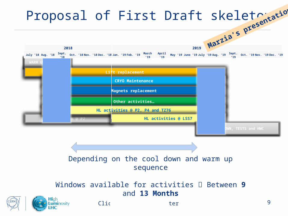
Click here to add footer 9
2018 2019
Proposal of First Draft skeleton
Depending on the cool down and warm up sequence
Windows available for activities Between 9 and 13 Months
WARM UP and TESTS
Lift replacement
CRYO Maintenance
Magnets replacement
Other activities…
Cool Down @ P7
HL activities @ P2, P4 and TZ76
HL activities @ LSS7
COOL DOWN, TESTS and HWC
July '18 Aug. '18Sept. '18
Oct. '18 Nov. '18 Dec. '18 Jan. '19 Feb. '19March
'19April '19 May '19 June '19 July '19 Aug. '19
Sept. '19
Oct. '19 Nov. '19 Dec. '19
Marzia’s presentation
Click here to add footer 10
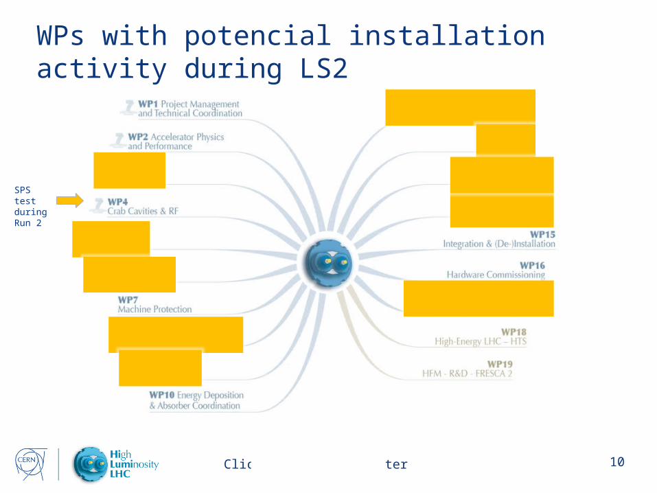
WPs with potencial installation activity during LS2
SPS test during Run 2
Click here to add footer 11
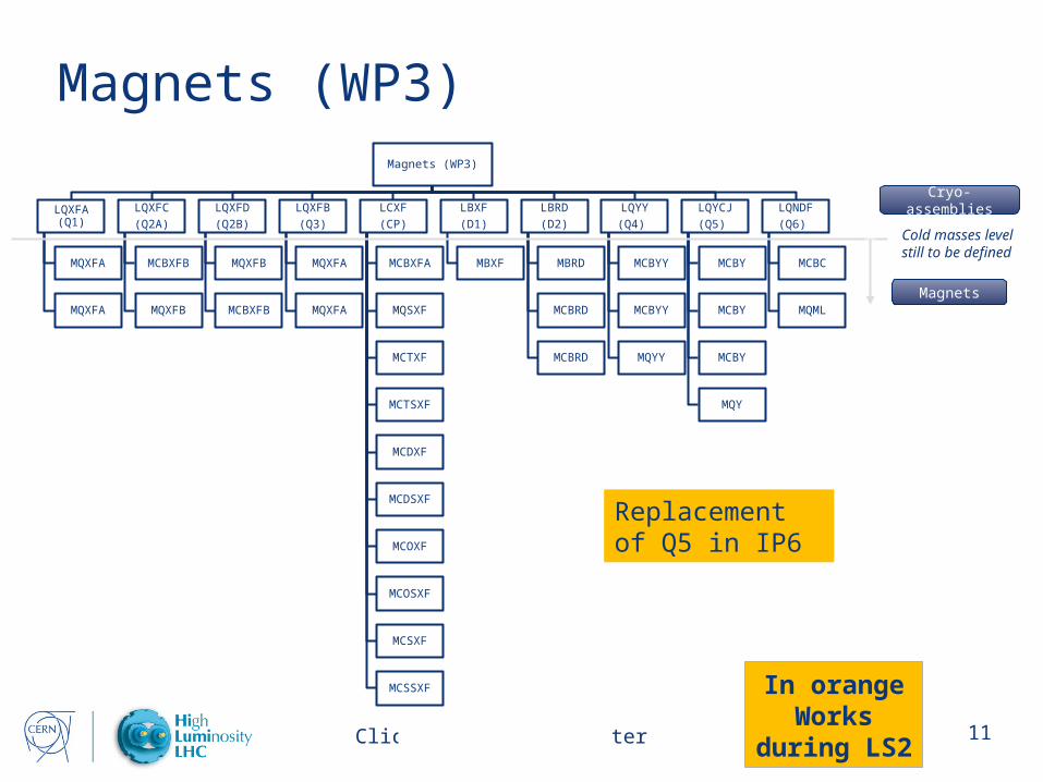
Magnets (WP3)Magnets (WP3)
LQXFA (Q1)
MQXFA
MQXFA
LQXFC
(Q2A)
MCBXFB
MQXFB
LQXFD
(Q2B)
MQXFB
MCBXFB
LQXFB
(Q3)
MQXFA
MQXFA
LCXF
(CP)
MCBXFA
MQSXF
MCTXF
MCTSXF
MCDXF
MCDSXF
MCOXF
MCOSXF
MCSXF
MCSSXF
LBXF
(D1)
MBXF
LBRD
(D2)
MBRD
MCBRD
MCBRD
LQYY
(Q4)
MCBYY
MCBYY
MQYY
LQYCJ
(Q5)
MCBY
MCBY
MCBY
MQY
LQNDF
(Q6)
MCBC
MQML
Cold masses levelstill to be defined
Cryo-assemblies
Magnets
Replacement of Q5 in IP6
In orange Works
during LS2
Click here to add footer 12
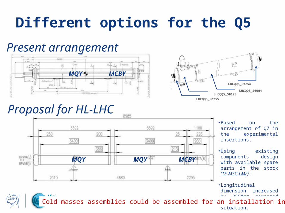
Different options for the Q5
Proposal for HL-LHC
Present arrangement
MQY MCBY
MQY MQY MCBY
• Based on the arrangement of Q7 in the experimental insertions.
• Using existing components design with available spare parts in the stock (TE-MSC-LMF).
• Longitudinal dimension increased by 3650mm compared to the present situation.
Cold masses assemblies could be assembled for an installation in LS2
LHCQQS_S0255
LHCQQS_S0123
LHCQQS_S0254
LHCQQS_S0004
Click here to add footer 13
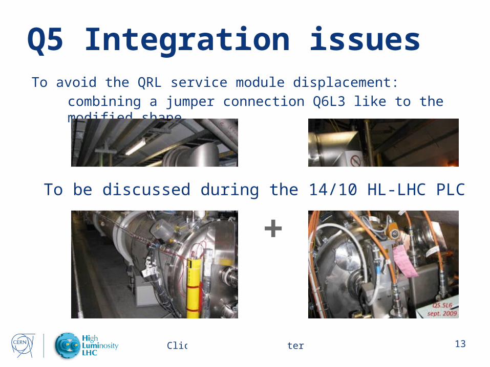
Q5 Integration issuesTo avoid the QRL service module displacement:
combining a jumper connection Q6L3 like to the modified shape
+To be discussed during the 14/10 HL-LHC PLC
Click here to add footer 14
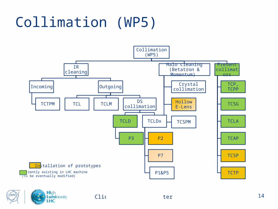
Collimation (WP5)
Collimation (WP5)
IR cleaning
Incoming
TCTPM
Outgoing
TCL TCLM DS collimation
TCLD
P3
TCLDx
P2
P7
P1&P5
Halo cleaning (Betatron & Momentum)
Crystal collimation
Hollow E-Lens
TCSPM
Present collimators
TCP, TCPP
TCSG
TCLA
TCAP
TCSP
TCTPCurrently existing in LHC machine(to be eventually modified)
Installation of prototypes

Click here to add footer 15
Cold Powering (WP6)
Cold Powering (WP6)
Tunnel Interconnection Cryostats
[DF]
Arc
[DFA]
DFAA
(L1)
DFAB
(R1)
DFAI
(L5)
DFAJ
(R5)
DFAM
(L7)
DFAN
(R7)
Matching sections
[DFM]
DFMA
(L1)
DFMB
(R1)
DFMI
(L5)
DFMJ
(R5)
DFMM
(L7)
DFMN
(R7)
Inner triplets
[DFX]
DFXA
(L1)
DFXB
(R1)
DFXI
(L5)
DFXJ
(R5)
Current Leads HTS
[DFLH]
Surface Interconnection Cryostats
[DFH]
Arc
[DFHA]
DFHAA
(L1)
DFHAB
(R1)
DFHAI
(L5)
DFHAJ
(R5)
DFHAM
(L7)
DFHAN
(R7)
Matching sections
[DFHM]
DFHMA
(L1)
DFHMB
(R1)
DFHMI
(L5)
DFHMJ
(R5)
Inner triplets
[DFHX]
DFHXA
(L1)
DFHXB
(R1)
DFHXI
(L5)
DFHXJ
(R5)
Superconducting links HTS
[DSH]
Arc
[DSHA]
DSHAA
(L1)
DSHAB
(R1)
DSHAI
(L5)
DSHAJ
(R5)
DSHAM
(L7)
DSHAN
(R7)
Matching sections
[DSHM]
DSHMA
(L1)
DSHMB
(R1)
DSHMI
(L5)
DSHMJ
(R5)
Inner triplets
[DSHX]
DSHXA
(L1)
DSHXB
(R1)
DSHXI
(L5)
DSHXJ
(R5)
Superconducting links
[DSL]
Matching sections
[DSLM]
DSLMM
(L7)
DSLMN
(R7)
Power
converters
Superconducting link P7
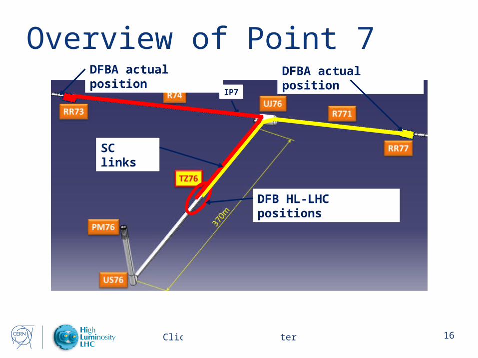
Click here to add footer 16
IP7
Overview of Point 7DFBA actual position DFBA actual position
DFB HL-LHC positions
SC links
Click here to add footer 17
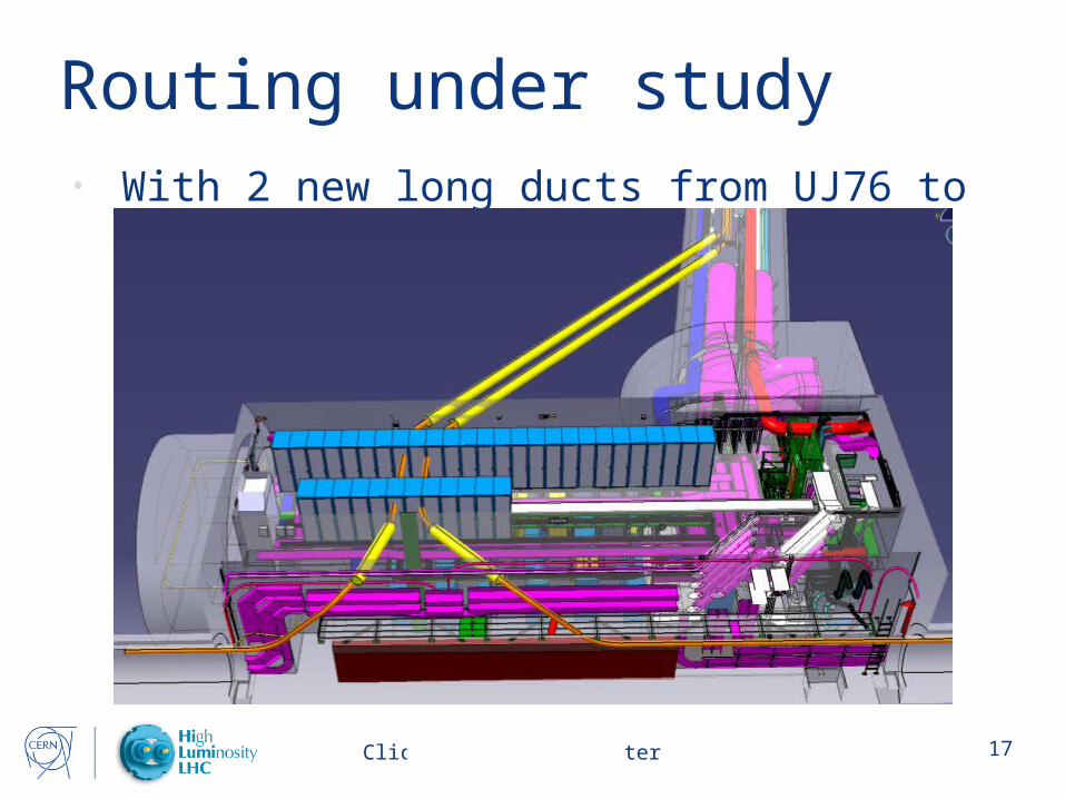
Routing under study• With 2 new long ducts from UJ76 to the TZ76
gallery
Click here to add footer 18
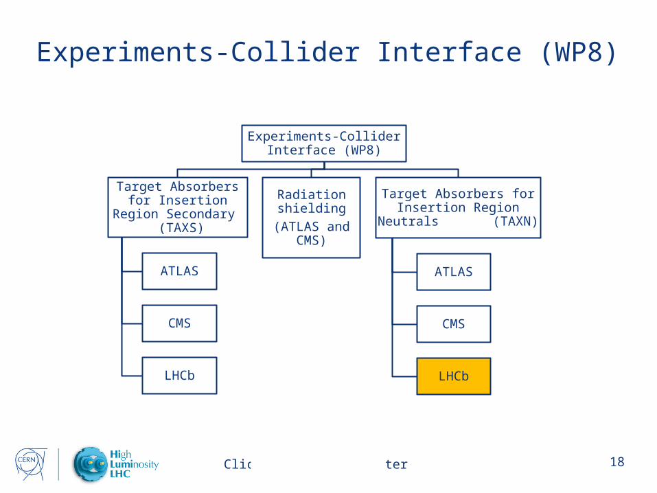
Experiments-Collider Interface (WP8)
Experiments-Collider Interface (WP8)
Target Absorbers for Insertion Region
Secondary (TAXS)
ATLAS
CMS
LHCb
Radiation shielding
(ATLAS and CMS)
Target Absorbers for Insertion Region Neutrals
(TAXN)
ATLAS
CMS
LHCb
Click here to add footer 19
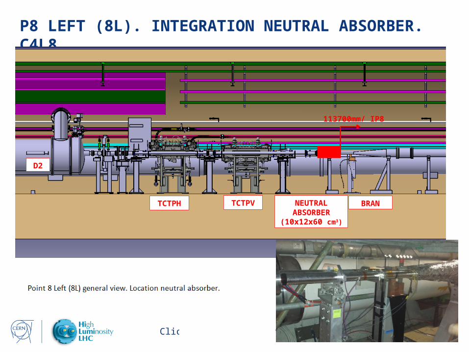
P8 LEFT (8L). INTEGRATION NEUTRAL ABSORBER. C4L8
D2
TCTPV NEUTRAL ABSORBER
(10x12x60 cm3)
113700mm/ IP8
TCTPH BRAN
Click here to add footer 20
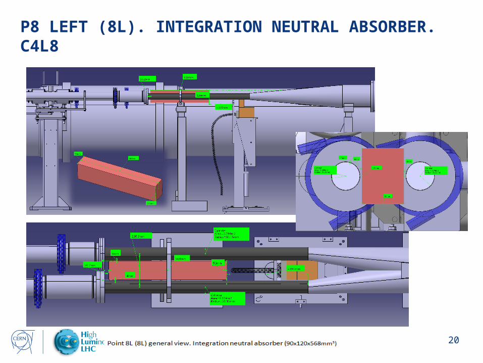
P8 LEFT (8L). INTEGRATION NEUTRAL ABSORBER. C4L8

Click here to add footer 21
Cryogenics (WP9)
Cryogenics
(WP9)
Storage
Warm
(QSV)
QSVA
(80 m3)
QSVB
(250 m3)
Cryogenic
(QSD)
QSDQ?
Refrigeration
Warm compressors
stations
QSCA
QSCB
QSCC
QSCD
QSCE
QSCF
QSCG
Refrigeration units
QSRA
QURA
QSRB
QURC
QURD
QURE
QURF
QSRG
QURCG
Dryers
(QSA)
Distribution
Warm piping
Surface
QSP
Shafts
QPP
Ring
Helium
(QRPR)
Warm recovery
(QRPW)
Cryogenic
Interconnection boxes
QUIA
QUIB
QUIC
QUIF
Transfer lines
Shafts
QPLB
QPLG
Underground
QULA
QULCA/B
QULF
Ring
QRL
Experimental areas and
LSS
QXL
Specific to HL-LHC
LHC existing
Modified for HL-LHC (already existing)
Cryogenics in P4
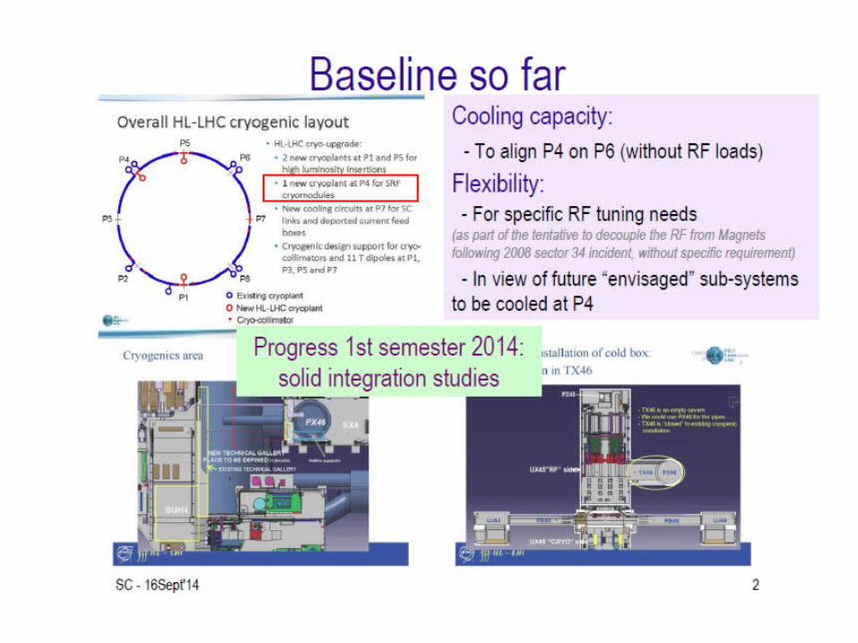
Click here to add footer 22

Click here to add footer 23
Cryogenics P4
Under study alternative scenarios that take in consideration different upgrade phases
Decision to be taken in Autumn 2015
Click here to add footer 24
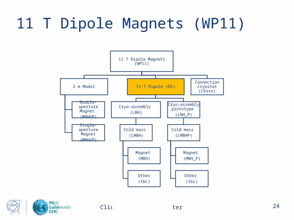
11 T Dipole Magnets (WP11)
11 T Dipole Magnets (WP11)
2 m Model
Double-aperture Magnet
(MBHDP)
Single-aperture Magnet
(MBHSP)
11-T Dipole (DS)
Cryo-assembly
(LBH)
Cold mass
(LMBH)
Magnet
(MBH)
Other
(tbc)
Cryo-assembly prototype
(LBH_P)
Cold mass
(LMBHP)
Magnet
(MBH_P)
Other
(tbc)
Connection cryostat (LExxx)
Click here to add footer 25
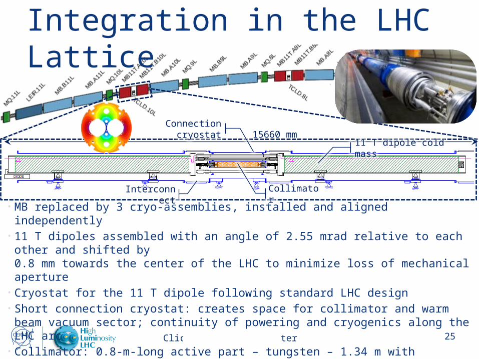
• MB replaced by 3 cryo-assemblies, installed and aligned independently• 11 T dipoles assembled with an angle of 2.55 mrad relative to each other and shifted by
0.8 mm towards the center of the LHC to minimize loss of mechanical aperture• Cryostat for the 11 T dipole following standard LHC design• Short connection cryostat: creates space for collimator and warm beam vacuum sector;
continuity of powering and cryogenics along the LHC arc• Collimator: 0.8-m-long active part – tungsten – 1.34 m with transitions and expansion joints• RF-shielded gate valves allow for independent operation of cold and room temperature
beam vacuum sectors
Integration in the LHC Lattice
Interconnect Collimator
11 T dipole cold mass
Connection cryostat15660 mm

Click here to add footer 26
Vacuum (WP12)
Vacuum (WP12)
Vacuum (V)
Beam screen
Non-shielded (VSC)
P2
(VSCG)
P8
(VSCG)
Shielded Beam Screen
(VSM)
P1
(VSMA)
P5
(VSMA)
Vacuum chambers (VCj)
Vacuum layout (LV)
LSS 1 LSS 5 LSS 4Insulation vacuum
(LVI)
By pass vacuum layout
(LV)
Vacuum layout experiments (LVXj)
ATLAS
CMS
LHCb
ALICE
j: 1, 2, 5, 8
Support to all WPs

Click here to add footer 27
Beam Diagnostics & Instrumentation (WP13)
Beam Diagnostics & Instrumentation (WP13)
Beam Loss Monitors
[BLM]
Cryogenic [BLMC]
RadHard electronics
[BLE]
Fast Wire scanners
[BWSF]
Beam Position Monitors
[BPM]
Cryogenic
Cryogenic stripline [BPMSQ]
Tungsten shielded cryogenic stripline
[BPMSQT]
Warm
Q1 stripline
[BPMSWQ]
Electronics
[BPE]
Luminosity Monitors
[BRANQ]
Wideband pick-ups
[BPW]
Synchrotron light monitors
[BSR]
Light Extraction
[BSRTM]
Interlock Abort Monitor
[BSRA]
Streak cameras [BSRS]
Halo diagnostics
[BSRH]
Beam Gas Vertex Detector
[BGV]
Chamber
[BGVC]
Detector
[BGVD]
Long Range Beam Beam Compensator
Collimator wire prototype
[TCTPW?]
Final
[BBLR]
Installation of prototypes
Click here to add footer 28
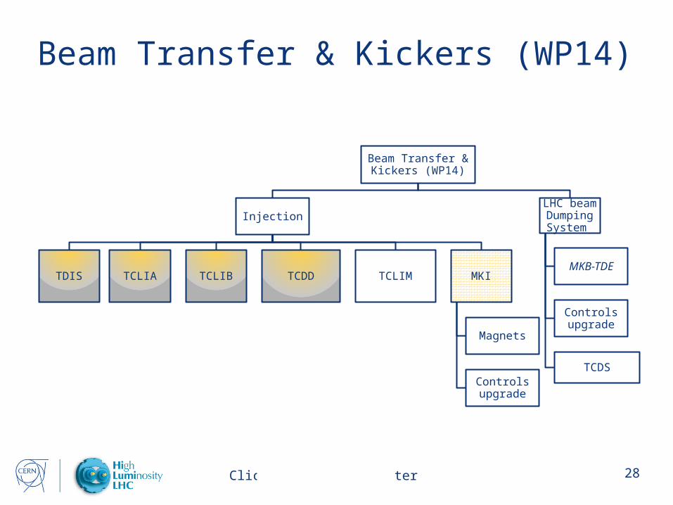
Beam Transfer & Kickers (WP14)
Beam Transfer & Kickers (WP14)
Injection
TDIS TCLIA TCLIB TCDD TCLIM MKI
Magnets
Controls upgrade
LHC beam Dumping System
MKB-TDE
Controls upgrade
TCDS
Click here to add footer 29
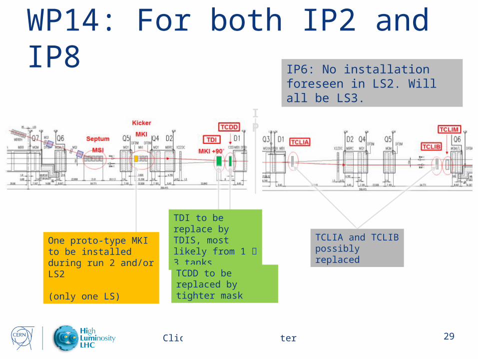
WP14: For both IP2 and IP8
IP
One proto-type MKI to be installed during run 2 and/or LS2
(only one LS)
TDI to be replace by TDIS, most likely from 1 3 tanks
TCDD to be replaced by tighter mask
TCLIA and TCLIB possibly replaced
IP6: No installation foreseen in LS2. Will all be LS3.

Click here to add footer 30
Surface Cryogenics P4
SUH4
PX46 SX4
EXISTING TECHNICAL GALLERY
NEW TECHNICAL GALLERYPLACE TO BE DEFINED (1.8mx2m) Halfen supports
Click here to add footer 31
Other infrastructures/works• Minor works for Cold Powering P7• Possibility to advance civil engineering
(excavation and buildings) in P1 and P5 and use of surface buildings for storage
• Installation work compatible with maintenance and consolidation work
• Importance of SM18 upgrade
Click here to add footer 32
Conclusions• Identify and prepare work that can be done
in LS2 on the time frame allocated for which the technology/solution is mature and can not bring any risk to the run 3 start date
• Integrate as early as possible our work planning with other LS2 Works
• Work together with the consolidation team to optimize resources
Click here to add footer 34
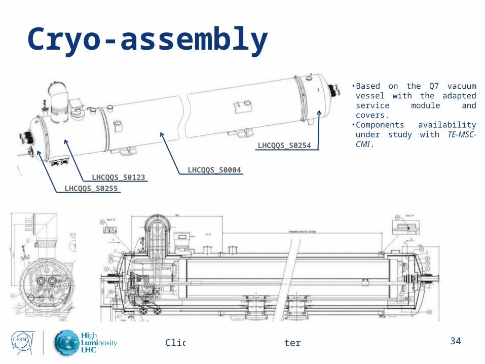
Cryo-assembly
LHCQQS_S0255
LHCQQS_S0123
LHCQQS_S0254
LHCQQS_S0004
• Based on the Q7 vacuum vessel with the adapted service module and covers.
• Components availability under study with TE-MSC-CMI.
Click here to add footer 3535
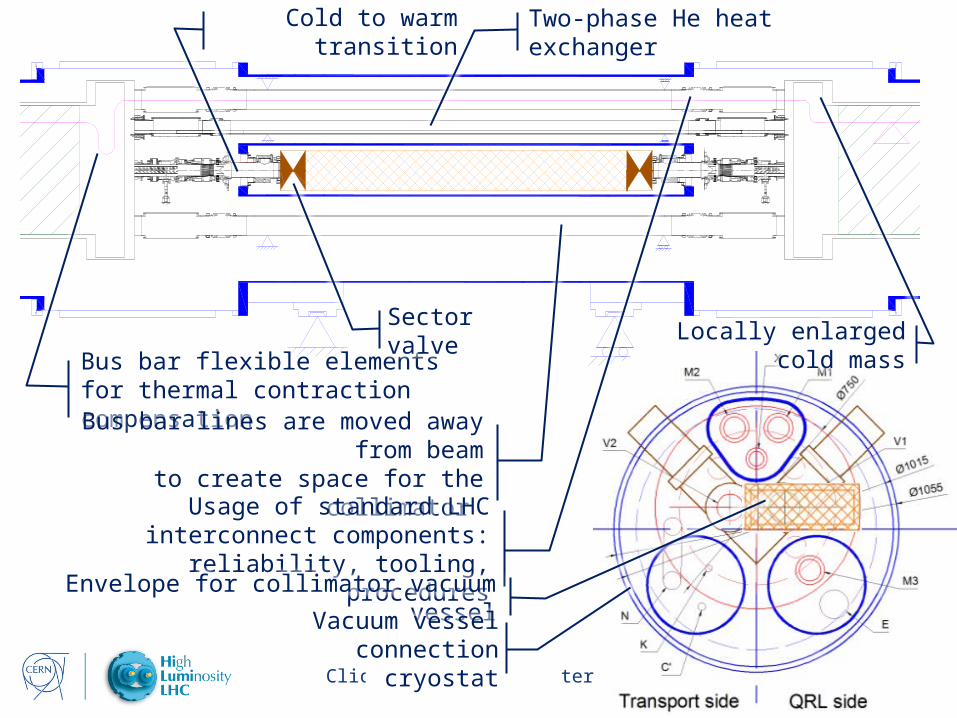
Bus bar flexible elements for thermal contraction compensation
Bus bar lines are moved away from beamto create space for the collimator
Cold to warm transition
Locally enlarged cold mass
Two-phase He heat exchanger
Sector valve
Usage of standard LHC interconnect components: reliability, tooling, procedures
Envelope for collimator vacuum vessel
Vacuum vesselconnection cryostat
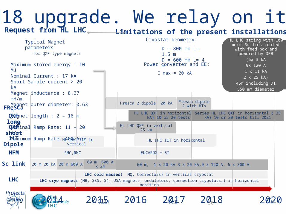
Click here to add footer 362014 2015 2016 2017 2018
LHC cryo magnets (MB, SSS, S4, USA magnets, ondulators, connection cryostats…) in horizontal position
LHC cold masses( MQ, Correctors) in vertical cryostat
20 m 20 kA 60 m 600 A x 24 60 m, 1 x 20 kA 3 x 20 kA,9 x 120 A, 6 x 300 A
HL LHC 11T in vertical
HL LHC QXF in vertical 25 kA
HL LHC 11T in horizontal
HL LHC QXF in horizontal ( 25 kA) 10 or 20 tests
Fresca 2 dipole 20 kA Fresca dipole 2 with HTs
HL LHC string with 100 m of Sc link cooled with feed box and
powered by DFB
(6x 3 kA
9x 120 A
1 x 11 kA
2 x 25 kA)
45m including D1
550 mm diameter
SMC,RMC EUCARD2 + 5T
Projects timing
Series HL LHC QXF in horizontal ( 25 kA) 10 or 20 tests till 2021
20 m 600 A
36
SM18 upgrade. We relay on itLimitations of the present installationsRequest from HL LHC
2020
Sc link
LHC
HFM
11T Dipole
QXF short
QXF long
FReSCa
Typical Magnet parameters for QXF type magnets
Maximum stored energy : 10 MJNominal Current : 17 kAShort Sample current > 20 kAMagnet inductance : 8,27 mH/mMagnet outer diameter: 0.63 mMagnet length : 2 – 16 m max.Nominal Ramp Rate: 11 – 20 A/sMaximum Ramp Rate: 400 A/s
Cryostat geometry:
Power converter and EE:
I max = 20 kA
D = 800 mm L= 1.5 mD = 600 mm L= 4 m


