CODE GENERATION FOR EMBEDDED REAL TIME SYSTEM MAHMOOD AGHAJANI SIROOS TALAB A project report submitted in fulfillment of the requirement for the award of the degree of Master of Science (Computer Science) Faculty of Computer Science and Information Systems Universiti Teknologi Malaysia APRIL 2010
Transcript
i
CODE GENERATION FOR EMBEDDED REAL TIME SYSTEM
MAHMOOD AGHAJANI SIROOS TALAB
A project report submitted in fulfillment of the
requirement for the award of the degree of
Master of Science (Computer Science)
Faculty of Computer Science and Information Systems
Universiti Teknologi Malaysia
APRIL 2010
iii
To my father and my brother (Arian)
To my respected supervisor
iv
ACKNOWLEDGEMENT
I would like to express my gratitude to all those who have given me the
possibility to complete this thesis. In particular, I wish to express my sincere
appreciation to my supervisor, Dr. Dayang Norhayati bt.Abang Jawawi who first
introduced me to academic software engineering research, and continuously guided me
with patient and encouragement along these two years, allowing me to go through my
research study with a balance of freedom and guidance. I also wish to thank to all my
colleagues especially Yavuz Selim Sengoz, Susila Sabil , and Mohd Zulkfli Bin Mohd
Zaki who have helped me to sort out my research.
v
ABSTRACT
Applying simple and reuse software to Embedded Real Time systems
poses significant challenges to industrial software which is applicable for large
expert domain. ERT Software development is complex due to multidisciplinary
knowlege required the development method such as software engineer, mechanical
engineer and electrical engineer. So, users of ERT software development framework
are not limited to desiners and developers who have software engineer background.
The developed framework consists of three main elements: a modified component
model, a component based timing analysis approach, and a code generator.An
important part of the ERT framework which helps to develop ERT system is called
code generator.Most of the code generators which are implemented by ERT
frameworks can not represent complexity of ERT system. Currently many Object
Oriented Analysis and Desigin methodology are available for implemenation of
code generators,but their model cannot support ERT Component Base
Development(CBD) directly . This motivate the study to propose criteria to evaluate
exiting ERT frameworks, Then code generation in support CBD. This study consider
further two important criteria which are Large Scale and Iterative development to be
integrated with a Component Oriented Programing (COP) by developing a code
generation tool. Thus , in this research a new tool was developed to support CBD
framework method for ERT systems. To evaluate the applicability of the new tool,an
ERT Case Study was designed and developed .Important features of COP and a
commercial tool wich is called Rational Rose are compared based on a case study in
this research. The result showed the advantages of COP code generation for
supporting CBD method.
vi
ABSTRAK
Mengaplikasi perisian yang ringkas dan guna-semula kepada Sistem
Terbenam Masa Nyata memberi cabaran yang signifikan kepada perisian industri
yang dapat dipakai oleh pakar domain yang besar. Pembangunan perisian ERT
adalah kompleks disebabkan oleh pengetahuan yang pelbagai disiplin memerlukan
kaedah pembangunan seperti jurutera perisian, jurutera mekanikal dan jurutera
elektrik. Oleh itu, pengguna rangka kerja perisian pembangunan ERT tidak terhad
hanya kepada pereka dan pembangun yang mempunyai latar belakang jurutera
perisian. Rangka kerja yang dibangunkan ini terdiri daripada tiga elemen utama:
komponen model yang diubahsuai, komponen berasaskan kaedah analisis masa, dan
penjana kod. Bahagian penting bagi rangkakerja ERT yang membantu untuk
membangunkan sistem ERT dipanggil kod penjana. Kebanyakan kod penjana yang
diimplemen oleh rangka kerja ERT tidak dapat mewakili kompleksiti sistem ERT. Di
waktu ini, kebanyakan metodologi Analisis dan Merekabentuk Berorientasikan
Objek boleh didapati bagi implementasi panjana kod, namun model mereka tidak
menyokong ERT Pembangunan Berorientasikan Komponen (CBD) secara terus. Ini
adalah motivasi bagi kajian ini bagi mengusulkan kriteria untuk menguji rangka kerja
ERT sedia ada, dan seterusnya menjana kod yang menyokong CBD. Kajian ini
mengambil kira dua kriteria utama iaitu pembangunan Skala Besar dan Berlelar.
Oleh itu, dalam kajian ini alat bantuan baru telah dibangunkan untuk menyokong
kaedah rangka kerja CBD bagi sistem ERT. Ciri penting bagi COP dan alat bantuan
komersial yang dipanggil Rational Rose dibandingkan berasaskan kajian kes di
dalam kajian ini. Hasil menunjukkan kelebihan COP menjana kod bagi menyokong
kaedah CBD.
vii
TABLE OF CONTENTS
CHAPTER TITLE PAGE
DECLARATION ii
DEDICATION iii
ACKNOWLEDGEMENTS iv
ABSTRACT v
ABSTRAK vi
TABLE OF CONTENTS vii
LIST OF TABLES xii
LIST OF FIGURES xiii
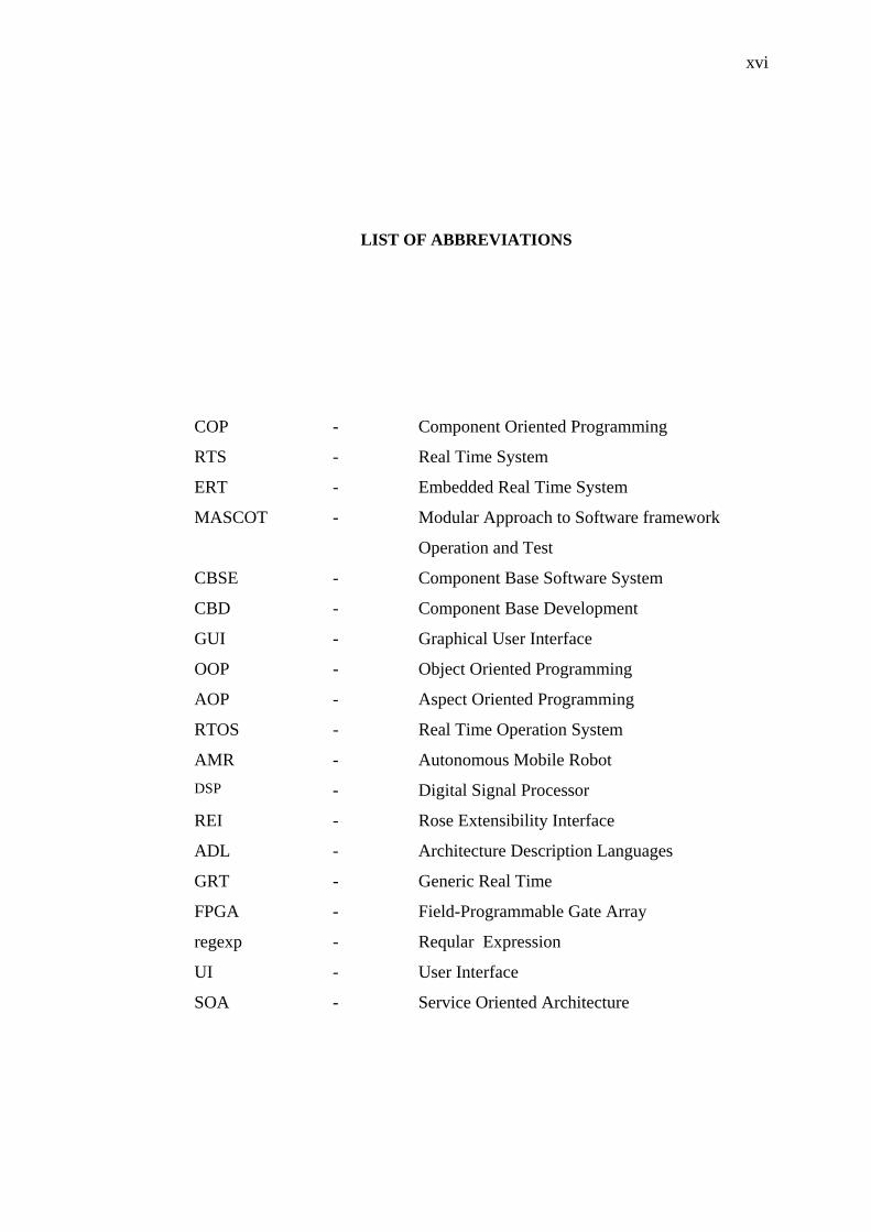
LIST OF ABBREVIATIONS
xvi
1 INTRODUCTION 1
1.1 Overview 1
1.2 Background of the problem 4
1.3 Problem Statement 7
1.4 Project Aim 8
1.5 Objective of Study 8
1.6 Scope of the Project 8
2 LITERATURE REVIEW 9
2.1 Overview 9
2.2 Code Generation Technology 10
viii
2.3 Pervious Reviews on Code Generation 11
2.3.1 Comparison of Dataflow Architecture and
Real Time Workshop Embedded Coder
11
2.3.2 Reviews the Object Oriented Design on
ERT
12
2.4 ERT Code Generation Frameworks 13
2.4.1 UML-RT 16
2.4.1.1 Time Managing 17
2.4.1.2 UML-RT and Code Generator
Features
20
2.4.1.3 UML-RT and Robot Controller 21
2.4.2 Giotto 24
2.4.2.1 Time Managing with Giotto
Compiler
26
2.4.2.2 Giotto Code Generation 31
2.4.2.3 A Giotto–Base Autonomous
Helicopter System
31
2.4.3 Simulink 33
2.4.3.1 Time Managing in Simulink 35
2.4.3.2 Simulink and Code Generator
(Real-Time Workshop) Features
36
2.4.4 Labview 36
2.4.4.1 Time Managing 37
2.4.4.2 Labview Code Generation 38
2.4.5 Component oriented programming (COP) 39
2.4.5.1 Mapping of component behaviour
to task and time managing
40
2.4.5.2 Analysis pattern for autonomous
Mobile Robot software
40
2.4.5.3 COP Framework 41
2.4.5.4 Components approach in COP 42
2.5 Discuss on the Evaluation of the Framework 43
ix
3 RESEARCH METHODOLOGY
3.1 Overviews 46
3.2 Research Methodology 47
3.3 Operational Research Framework 49
3.4 ERT Case Study 51
3.4.1 Card and Fingerprint based Time Recording Terminal
52
3.4.2 Concurrency operation in STPro 54
4 CODE GENERATOR FOR EMBEDDED REAL
TIME SOFTWARE
55
4.1 Overviews 55
4.2 Criteria of Evaluations for CBD Methodologies in
ERT Code Generator
56
4.3 Reason on choosing the four criteria 58
4.4 UML RT 58
4.4.1 Iterative development in UML RT 59
4.4.2 Optimized Design Concept 60
4.4.3 Large scale development in UML RT 61
4.4.4 Integration and adaptation 62
4.5 Giotto 62
4.5.1 Iterative development 63
4.5.2 Optimization development 64
4.5.3 Large scale development 66
4.5.4 Interaction and adaptation 67
4.6 Simulink 67
4.6.1 Iterative development 68
4.6.2 Optimizing generated code 71
4.6.3 Large-scale development 76
4.6.4 Integration and adaption 77
4.7 Labview 77
4.7.1 Iteration development on Labview 77
4.7.2 Optimizing Generated Code 79
4.7.3 Large scale development 81
x
4.7.4 Integration and adaption 81
4.8 Discussion on the Evaluation of Criteria for Code Generators
81
4.9 Discusstion 84
5 RATIONAL ROSE REAL TIME TOOL 85
5.1 Introduction 85
5.2 Component Composition 86
5.3 Code generation 90
5.3.1 Capsule 91
5.3.2 Capsule State Diagrams 92
5.3.3 Classes 93
5.3.4 Associations 93
5.3.5 Dependency 95
5.3.6 Internal messages 95
5.4 Following criteria by Rational Rose RT 97
5.4.1 Supporting the Large Scale by Rational
Rose RT
98
5.4.2 Supporting the Iterative Development by
Rational Rose RT
101
5.4.3 Discussion
102
6 COP TOOL 104
6.1 Introduction 104
6.2 COP TOOL requirement 105
6.2.1 Module 1:Component Development 105
6.2.2 Module 2:Component Integration 105
6.2.3 Module 3: Code generation 106
6.3 COP tool design 106
6.3.1 COP Composition Class Diagram 108
6.3.2 COP Code Generation class diagram 108
6.3.3 User Interface 112
6.3.4 The Tool architecture design 115
6.4 Following criteria by COP tool 117
xi
6.4.1 Supporting the Large Scale by COP tool 117
6.4.2 Supporting the Iterative Development by
COP tool
119
6.4.3 Discussion
121
7 CONCLUSION 124
7.1 Summary 115
7.2 Research Contribution 126
7.3 Future works
127
REFERENCES 128
xii
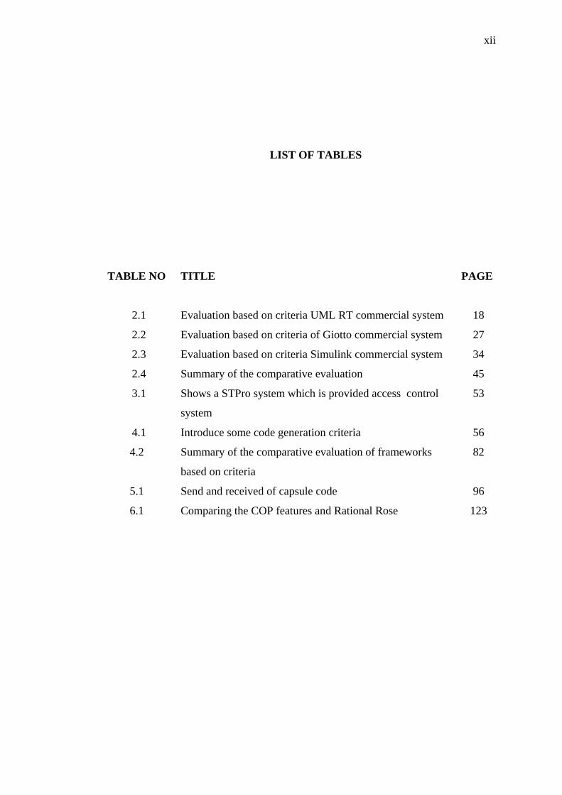
LIST OF TABLES
TABLE NO TITLE PAGE
2.1 Evaluation based on criteria UML RT commercial system 18
2.2 Evaluation based on criteria of Giotto commercial system 27
2.3 Evaluation based on criteria Simulink commercial system 34
2.4 Summary of the comparative evaluation 45
3.1 Shows a STPro system which is provided access control
system
53
4.1 Introduce some code generation criteria 56
4.2 Summary of the comparative evaluation of frameworks
based on criteria
82
5.1 Send and received of capsule code 96
6.1 Comparing the COP features and Rational Rose 123
xiii
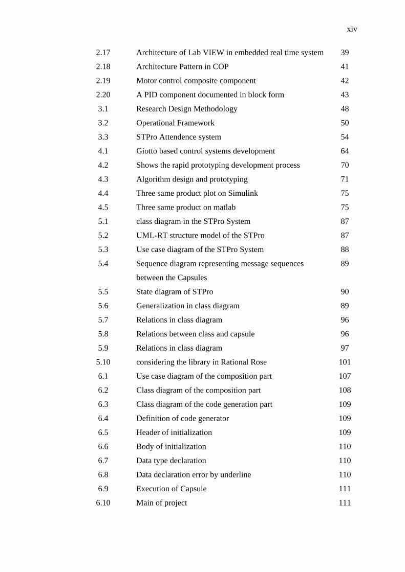
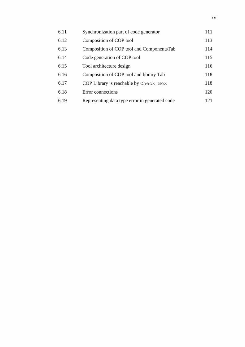
LIST OF FIGURES
FIGURE NO TITLE PAGE
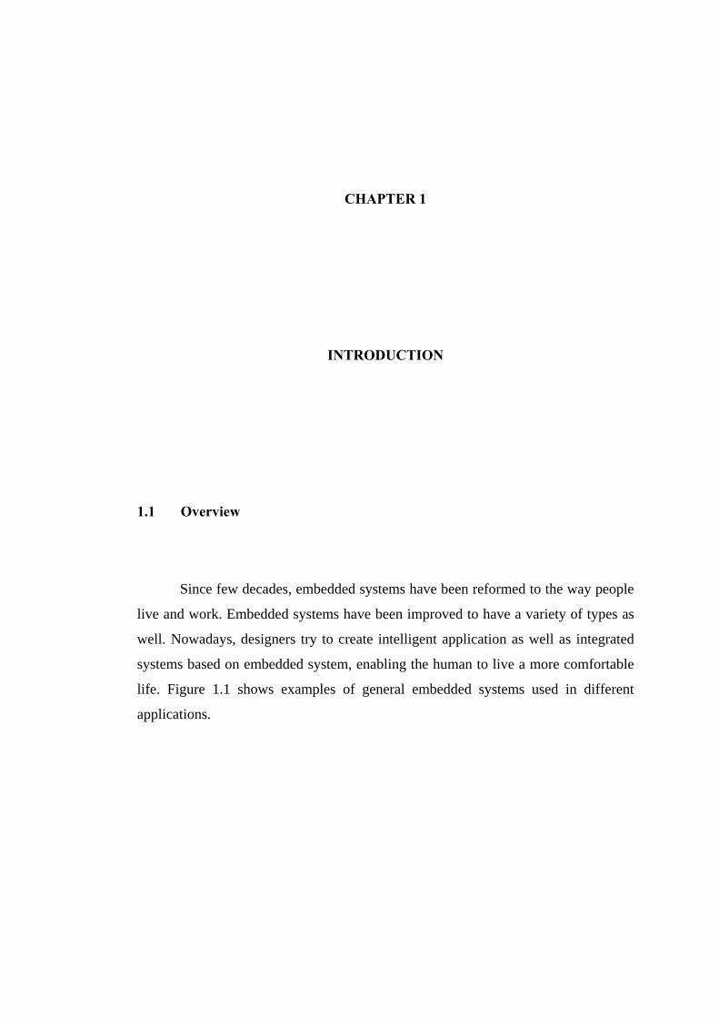
1.1 Example of embedded systems 2
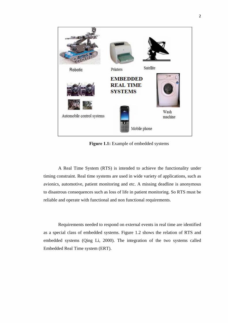
1.2 Embedded real time system 3
2.1 Programming model of a node processor (wikender,
1999).
14
2.2 Sequence diagram with time consuming 17
2.3 Timing diagram example 18
2.4 Capsule structure diagrams 22
2.5 Capsule structure diagrams 22
2.6 Capsule state transaction diagrams 23
2.7 Component diagram 23
2.8 Traditional control systems development process 25
2.9 The Giotto based control system development 25
2.10 Giotto time tasking diagram 26
2.11 Giotto program example (control off or controller on
specification on helicopter controller)
29
2.12 Workflow of the design framework that iteratively
refines code generation using schedulability
30
2.13 Time tasking on Giotto 32
2.14 There are no race conditions 32
2.15 The Giotto case block in simulink 33
2.16 Typical output logic for a digital delay generator 38
xiv
2.17 Architecture of Lab VIEW in embedded real time system 39
2.18 Architecture Pattern in COP 41
2.19 Motor control composite component 42
2.20 A PID component documented in block form 43
3.1 Research Design Methodology 48
3.2 Operational Framework 50
3.3 STPro Attendence system 54
4.1 Giotto based control systems development 64
4.2 Shows the rapid prototyping development process 70