21
communications URC Utility Relay Company i-comm modbus / rs-485
communications
URC Utility Relay Company
i-comm modbus / rs-485
instruction manual
C h a g r i n F a l l s , O H 4 4 0 2 3 P h o n e : 8 8 8 . 2 8 9 . 2 8 6 4w w w . u t i l i t y r e l a y . c o m
AC-PROCommunicatingTrip Units
ZERO-HertzCommunicatingTrip Units

Table of Contents 1.0 Introduction ------------------------------------------------------ 1 2.0 AC-PRO Communications Components ------------------- 2 2.1 AC-PRO Trip Unit ----------------------------------------------- 2 2.2 PT Module --------------------------------------------------------- 2 2.3 AC-PRO Breaker Wiring ---------------------------------------- 3 3.0 ZERO-Hertz Communications Components -------------- 4 3.1 ZERO-Hertz Trip Unit ------------------------------------------- 4 3.2 ZERO-Hertz Breaker Wiring ----------------------------------- 5 4.0 System Components - Computer Hardware -------------- 6 4.1 RS-485 Direct ----------------------------------------------------- 6 4.2 RS-232 to RS-485 Conversion --------------------------------- 7 4.3 Ethernet ------------------------------------------------------------ 8 4.4 LCI Ethernet ------------------------------------------------------ 9
5.0 System Components – Software------------------------------ 9 5.1 Trip Unit Programming ------------------------------------------ 10 5.2 MODBUS --------------------------------------------------------- 10 5.3 DDE Addressing (with EXCELTM) ----------------------------- 11 6.0 Technical Support ---------------------------------------------- 11
Appendix A AC-PRO MODBUS RTU Item Names ---------------- 12 Appendix B ZERO-Hertz MODBUS RTU Item Names ------------ 15
January 2013 Revision 1.4

AC-PRO / ZERO-Hertz, Communications System - Instruction Manual
Page 1
Creating a complete power monitoring and communications system for a low voltage power distribution system is easy with Utility Relay Company’s AC-PRO and ZERO-Hertz communicating trip unit. The trip units communicate using industry standard MODBUS RTU protocol through a single shielded twisted pair wire connected to the RS-485 port. A number of trip units can be daisy-chained together to simplify installation. Information available from an AC-PRO trip unit at each breaker includes:
• Currents, 3-phase (±2% accuracy for currents between 10% and 150% of the CT rating) • Voltages, 3-phase • KW, 3-phase (±5% accuracy for currents between 10% and 150% of the CT rating) • KWH, Total • KVA, 3-phase • Power Factor Data • Breaker Position • Overload and Alarm Conditions • Last Trip Data • Phase Currents at the Time of Trip • Trip Counter
Information available from a ZERO-Hertz trip unit at each breaker includes:
• DC Current ((±10% accuracy for currents between 10% and 150% of the transducer rating) • Ground Fault Current (if applicable) • Current Direction • Overload and Alarm Conditions • Last Trip Data • Trip Current at the Time of Trip • Trip Counter
A host PC running OPC software with Modbus device drivers collects information from the trip units. The driver interrogates each trip unit individually and reports that information back to the host PC applications on a continual basis. Additional trip units can be added to the system by simply providing the new trip unit’s ADDRESS to the OPC software. AC-PRO and ZERO-Hertz trip units are compatible with the MODBUS RTU communication protocol supplied with most HMI systems such as Wonderware’ s InTouch TM, Intellution TM, Square D’s PowerLogic SMS-3000 TM and ION Enterprise TM, and Power Measurements PEGASYS TM.
1.0 Introduction
Utility Relay Company
Page 2
An AC-PRO MODBUS Communications system consists of the following hardware components: 1. AC-PRO Trip Unit and breaker retrofit components. 2. Host PC (supplied by others). 3. Cabling Topology (supplied by others).
Additional components to consider include:
1. OPC software with Modbus device drivers (supplied by others). 2. Modbus RTU/Ethernet converter (supplied by others). 3. Human-Machine Interface (HMI) System (supplied by others).
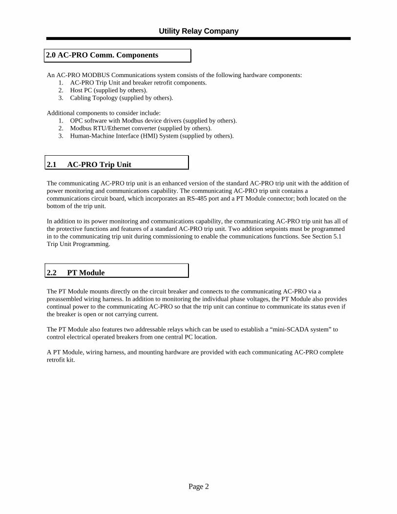
2.1 AC-PRO Trip Unit The communicating AC-PRO trip unit is an enhanced version of the standard AC-PRO trip unit with the addition of power monitoring and communications capability. The communicating AC-PRO trip unit contains a communications circuit board, which incorporates an RS-485 port and a PT Module connector; both located on the bottom of the trip unit. In addition to its power monitoring and communications capability, the communicating AC-PRO trip unit has all of the protective functions and features of a standard AC-PRO trip unit. Two addition setpoints must be programmed in to the communicating trip unit during commissioning to enable the communications functions. See Section 5.1 Trip Unit Programming.
2.2 PT Module The PT Module mounts directly on the circuit breaker and connects to the communicating AC-PRO via a preassembled wiring harness. In addition to monitoring the individual phase voltages, the PT Module also provides continual power to the communicating AC-PRO so that the trip unit can continue to communicate its status even if the breaker is open or not carrying current. The PT Module also features two addressable relays which can be used to establish a “mini-SCADA system” to control electrical operated breakers from one central PC location. A PT Module, wiring harness, and mounting hardware are provided with each communicating AC-PRO complete retrofit kit.
2.0 AC-PRO Comm. Components

AC-PRO / ZERO-Hertz, Communications System - Instruction Manual
Page 3
The communicating AC-PRO is provided with a quick disconnect communications cable assembly. The cable assembly features a heavy-duty twist-lock connector and a terminal block, which mounts inside the switchgear. The purpose of the terminal block is to provide a connection location for the twisted pair wire as it is daisy-chained from cell to cell in a switchgear lineup. This enables any individual communicating AC-PRO (mounted on a circuit breaker) to be removed without disrupting communications between the other communicating AC-PRO trip units.
9V Lithium
Long-Life Battery
AC TRIP UNIT
UTILITY RELAY COMPANY
SAVE
SELF TEST OK
PICK-UP
PUSH TO VIEWLAST TRIP DATA
AND SETTINGSREVIEW
ADJUSTDISPLAY
PUSH TO
CONTRAST
With
2.3 AC-PRO Breaker Wiring

Utility Relay Company
Page 4
A ZERO-Hertz MODBUS Communications system consists of the following hardware components:
1. Communicating ZERO-Hertz Trip Unit and breaker retrofit components. 2. Host PC (supplied by others). 3. Cabling Topology (supplied by others).
Additional components to consider include:
4. OPC software with Modbus device drivers (supplied by others). 5. Modbus RTU/Ethernet converter (supplied by others). 6. Human-Machine Interface (HMI) System (supplied by others).
The ZERO-Hertz trip unit is available in four models: Method of DC Current Sensing Model Number: Transducers Only Transducer or Shunt Input Communications B-201 YES B-202 YES YES B-203 YES B-204 YES YES Trip unit models B-202 and B-204 are equipped with an RS-485 MODBUS communications port. This port allows the trip unit to communicate with a host PC or other RS-485-based communications system. In addition to its continuous DC current monitoring and communications capability, the communicating ZERO-Hertz has all of the protective functions and features of a non-communicating ZERO-Hertz trip unit. Two addition setpoints must be programmed in to the communicating trip unit during commissioning to enable the communications functions. See Section 5.1 Trip Unit Programming.
3.0 ZERO-Hertz Comm. Components
3.1 ZERO-Hertz Trip Unit
AC-PRO / ZERO-Hertz, Communications System - Instruction Manual
Page 5
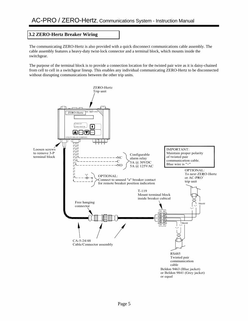
The communicating ZERO-Hertz is also provided with a quick disconnect communications cable assembly. The cable assembly features a heavy-duty twist-lock connector and a terminal block, which mounts inside the switchgear. The purpose of the terminal block is to provide a connection location for the twisted pair wire as it is daisy-chained from cell to cell in a switchgear lineup. This enables any individual communicating ZERO-Hertz to be disconnected without disrupting communications between the other trip units.
UTILITY RELAY COMPANY
SELF TEST OK
ENTER
PICK-UP
MENU
WITH QUICK-TRIP Long-Life Battery
9V Lithium
With
3.2 ZERO-Hertz Breaker Wiring

Utility Relay Company
Page 6
URC trip units communicate over the RS-485 interface at 9600 Baud, with 8 data bits, 1 stop bit and no parity using the Modbus RTU communications protocol. There are four simple hardware configurations to connect between a PC and a communicating URC trip unit on a breaker.
Connecting trip units directly to a PC is an easy way to set up a stand-alone system. The major benefit is that a stand-alone system is that it does not require a large initial investment in hardware. The system can start out small, yet it is flexible enough to allow additional trip units to be added to the system at any time.
Workstation
SUBSTATION #1 Up to 32 trip unitscan be daisychained
together.
SUBSTATION #2SUBSTATION #3
As system demands grow, additional twisted pairs of wire can be added, each twisted pair capable of supporting an additional 32 AC-PRO or ZERO-Hertz communicating trip units. The host PC can also be connected to a Local Area Network (LAN), allowing other computer sites access to AC-PRO information. Cable requirements:
• Belden 9463 shielded twisted pair (or equivalent) cabling is recommended • Maximum cable length is 4000 feet.
4.0 System Components-Computer Hardware
4.1 RS-485 Direct

AC-PRO / ZERO-Hertz, Communications System - Instruction Manual
Page 7
RS-232 communications is a convenient method to periodically monitor trip units without incurring the expense of a network. RS-232 to RS-485 converters and hardware are readily available and inexpensive. Using a Laptop When continual power monitoring and communications is not necessary, a laptop computer is a very useful tool. A substation can be wired for communications with the communications cable terminating at an inexpensive RS-232 to RS-485 converter located in the substation. When required, a laptop computer can be connected directly to the RS-232 computer for periodic monitoring. At any time, the RS-232 to RS-485 converter can be removed, and the substation can be connected to a larger power monitoring system with the addition of an LCI (see Section 4.4) or other RS-485 to Ethernet Converter.
SUBSTATION #1
Laptop Computer
Up to 32 trip unitscan be daisychained
together.
SUBSTATION #2SUBSTATION #3
RS232to
RS485
RS232to
RS485
RS232to
RS485
RS-232 Converters Most, if not all, RS-232 to RS-485 converters and boards will have 4 wire connections TX+, TX- RX+, and RX-. The trip units use a 2 wire connection system, so at some convenient point, usually right at the converter or board connector, connect as follows:
TX+ and RX+ together TX- and RX- together
Shielded twisted pair cable should be used between the RS-232 to RS-485 converter and the trip units (Belden 9463 or equivalent cable is recommended).
4.2 RS-232 to RS-485 Conversion
Utility Relay Company
Page 8
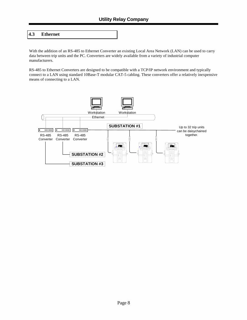
With the addition of an RS-485 to Ethernet Converter an existing Local Area Network (LAN) can be used to carry data between trip units and the PC. Converters are widely available from a variety of industrial computer manufacturers. RS-485 to Ethernet Converters are designed to be compatible with a TCP/IP network environment and typically connect to a LAN using standard 10Base-T modular CAT-5 cabling. These converters offer a relatively inexpensive means of connecting to a LAN.
EthernetWorkstation Workstation
SUBSTATION #3
SUBSTATION #2
SUBSTATION #1
RS-485Converter
RS-485Converter
RS-485Converter
Up to 32 trip unitscan be daisychained
together.
4.3 Ethernet

AC-PRO / ZERO-Hertz, Communications System - Instruction Manual
Page 9
The LCI (Local Communications Interface), manufactured by Utility Relay Company, is a substation monitor that continuously monitors up to 32 AC-PRO and/or ZERO-Hertz communicating trip units that are connected to the LCI’s RS-485 port. The LCI offers three key benefits:
1. The 4-line X 20-character display provides easy monitoring of a critical power and trip data from any trip unit connected to the RS-485 port.
2. The built-in Ethernet port acts as a Modbus RTU to Modbus Ethernet converter and easily connects to a LAN with a simple CAT-5 cable. A unique IP address for the LCI is user-programmable from the LCI’s front panel.
3. Embedded Web Pages in the LCI provide critical information across the LAN with no additional software to install or setup. Information can be accessed by typing the LCI’s IP address in the command line of any standard web browser on the LAN.
Contact Utility Relay Company for more information about the LCI.
EthernetWorkstation Workstation
LCI LCI LCI
SUBSTATION #3
SUBSTATION #2
SUBSTATION #1 Up to 32 trip unitscan be daisychained
together.
In addition to AC-PRO and/or ZERO-Hertz communicating trip units equipped with an RS-485 port, the following additional software may be required:
1. OPC software with a Modbus device driver. 2. EXCELTM or LOTUS 1-2-3TM can be used to view information provided by the OPC software. 3. Human-Machine Interface (HMI) System. These systems are used to view trip unit information graphically
and often contain their own compatible MODBUS Driver.
4.4 LCI Ethernet
5.0 System Components - Software

Utility Relay Company
Page 10
Both the AC-PRO and the ZERO-Hertz communicating trip units have two additional programmable setpoints that are not found on the non-communicating trip units. Those two setpoints are
• ADDRESS• REPLY DELAY
These setpoints need to be programmed during the normal commissioning of the trip unit (Refer to the section on Commissioning in the AC-PRO or ZERO-Hertz Instruction Manual). The setpoints appear after all of the Pick-Up and Delays settings have been made.
ADDRESS Each trip unit that shares the same twisted pair must have a unique address. The address is selectable from 1 to 127 in increments of 1. In most applications only addresses 1 thru 32 will be used due to the limitations of RS-485 communications.
The ADDRESS identifies each individual trip unit connected to the same twisted pair wire. NOTE: Two trip units can have the same ADDRESS as long as they are not connected to the PC, Ethernet converter or RS-232 converter via the same twisted pair cable.
REPLY DELAY The REPLY DELAY set point is the minimum delay between the trip unit’s receipt of a MODBUS packet and its reply. Adjusting it enables the trip unit to operate properly with other manufacturers’ MODBUS RS-485 connections. The reply delay can be either 5 or 10 milliseconds.
The factory default of this set point is 5 milliseconds.
The OPC software with Modbus device drivers runs on the Host PC and communicates with the trip units via Modbus communications protocol. It creates the communications messages, sends them, and retrieves the responses. This data can then be shared with most WINDOWSTM programs requesting information (via DDE). DDE is supported by most HMI systems.
Other programs which accept DDE include EXCELTM, WORDTM and LOTUS 1-2-3TM. These programs do not contain OPC software. A downloadable version of OPC software with Modbus device drivers (both Modbus RTU and Modbus Ethernet) from KEPWARE TM (along with installation instructions) is available at:
http://www.utilityrelay.com/products/Communications.html
The free version of this software provides a 2-hour continuous runtime environment with an unlimited number of restarts.
The MODBUS Driver runs in the background on the host PC and immediately begins to communicate with all of the trip units connected to the PC when the program is started. The only time that the software needs to be modified is when a trip unit is added or removed from the system.
5.1 Trip Unit Programming
5.2 MODBUS

AC-PRO / ZERO-Hertz, Communications System - Instruction Manual
Page 11
Dynamic Data Exchange (DDE) is a programming format that allows most programs running under WINDOWSTM to request and receive data from other programs. Programs such as EXCELTM or LOTUS 1-2-3TM use DDE requests to get specific data from OPC software that supports Modbus device drivers. DDE requests include a formatted “address” of the data being sought. WINDOWSTM is responsible for processing those requests and retrieving data from the MODBUS-DDE Driver. DDE data consists of the following components:
1. DDE Source Name 2. Topic Name 3. Item Name
DDE Source Name – This is the name of the DDE Driver being used. Topic Name – This is the name of the trip unit to be addressed. The Topic Name must be defined in the MODBUS-DDE Driver (by its ADDRESS and COM port or TCP/IP settings). Item Name – The data point to read or write. “Item Names” are frequently numbers, but are still called “Names”. The format of a DDE address is as follows: DDE SourceName | TopicName!’ItemName’ For example, in Microsoft ExcelTM, the following command could be typed into a cell to retrieve a piece of data (NOTE: The following syntax is for InTouch Wonderware): MODBUS|BREAKER1!’256 IR’ Where: MODBUS is the DDE Source Name. BREAKER1 is the Topic Name defined by the user using MODBUS. 256 IR is the Item Name of the desired piece of information from the trip unit.
NOTE: The AC-PRO and ZERO-Hertz are compatible with most MODBUS drivers.
You will need to consult the specific MODBUS driver manufacturer for the proper syntax. See Appendix A for a complete list of available Item Names for AC-PRO trip units. See Appendix B for a complete list of available Item Names for ZERO-Hertz trip units.
For technical support, contact Utility Relay Company 888-289-2864, or visit us on the web at: www.utilityrelay.com
5.3 DDE Addressing with EXCELTM
6.0 Technical Support

Utility Relay Company
Page 12
PRODUCT UPDATES THAT REQUIRED NEW MODBUS (DDE) ITEMS
Date New AC-PRO
feature Did Any Old Register Addresses Change?
February 1, 2003 Kilowatt Hours Yes† February 1, 2006 Quick-Trip No
November 1, 2011 KWH No
† The old Register Address are shown in italics, to the left of the new Register Address.
Old Register Address
Item Register Address Description (Data Point Name) Unit Size Data
Type 83 Force Reset N/A Word OC 84 Force Trip N/A Word OC 86 Force Clear Last Trip Data N/A Word OC 111 Force Clear KW-Hrs (after 2/1/03) N/A Word OC 112 Force Relay 1 (on for 100mS) N/A Word OC 113 Force Relay 2 (on for 100mS) N/A Word OC 256 Current Phase A Amps Word IR 257 Current Phase B Amps Word IR 258 Current Phase C Amps Word IR 259 Current GF Amps Word IR 260 Current UB % Word IR 262 Voltage AG Volts Word IR 263 Voltage BG Volts Word IR 264 Voltage CG Volts Word IR 265 Voltage AB Volts Word IR 266 Voltage BC Volts Word IR 267 Voltage CA Volts Word IR 268 KW Phase A kW Word IR 269 KW Phase B kW Word IR 270 KW Phase C kW Word IR
272 271 KVA Phase A kVA Word IR 273 272 KVA Phase B kVA Word IR 274 273 KVA Phase C kVA Word IR
274 KW-Hrs Register 3 0.1 KWH * 232 Word IR 275 KW-Hrs Register 2 0.1 KWH * 216 Word IR 276 KW-Hrs Register 1 0.1 KWH Word IR
271 277 KW Signs & Lead/Lag PF N/A Word IR Bit 0; Phase A, 1 = Lead PF, 0 = Lag PF Bit 1; Phase B, 1 = Lead PF, 0 = Lag PF Bit 2; Phase C, 1 = Lead PF, 0 = Lag PF Bit 8; Phase A KW, 1 = Pos, 0 = Neg Bit 9; Phase B KW, 1 = Pos, 0 = Neg Bit 10; Phase C KW, 1 = Pos, 0 = Neg
Bit 11; KW-Hrs, 1 = Pos, 0 = Neg (N/A/ for trip units made before 2/1/2003)
Appendix A AC-PRO MODBUS RTU Item Names

AC-PRO / ZERO-Hertz, Communications System - Instruction Manual
Page 13
Old Register
Address Item Register
Address Description (Data Point Name) Unit Size Data Type
275 278 Alarm Code N/A Word IR Bit 0; 1 = Trip Output Bit 1; 1 = Current > LT Pickup Bit 3; 1 = Actuator Disconnected
Bit 4; 1 = Memory Error Bit 6; 1 = A/D Error
Bit 8; 1 = Breaker Closed, 0 = Breaker Open or Feature Unused Bit 9; 1 = Times 10 Range Bit 11; 1 = Divide by 10 Range
276 279 CT Rating Amps Word HR
277 280 LT Pickup Amps Word HR
278 281 LT Delay Sec. Word HR Value stored is 2 times the actual delay in seconds
279 282 ST Pickup Amps Word HR
280 283 ST Delay Sec. Word HR Binary 0 =. 07 Sec Delay Band Binary 1 = .10 Sec Delay Band Binary 2 = .15 Sec Delay Band Binary 3 = .20 Sec Delay Band Binary 4 = .30 Sec Delay Band Binary 5 = .40 Sec Delay Band (N/A for trip units made before 2/1/03)
281 284 ST I2 T N/A Word HR Bit 0; 0 = Off, 1 =On
282 285 I Pickup Amps Word HR
283 286 GF Pickup Amps Word HR
284 287 GF Delay Sec. Word HR Binary 0 = .10 Sec Delay Band Binary 1 = .20 Sec Delay Band Binary 2 = .30 Sec Delay Band Binary 3 = .40 Sec Delay Band Binary 4 = .50 Sec Delay Band
285 288 GF I2 T N/A Word HR Bit 0; 0 = Off, 1 = On
286 289 U/B Pickup % Word HR
287 290 U/B Delay Sec. Word HR
288 291 Trip Unit Address N/A Word HR
289 292 Reply Delay mS Word HR
290 293 Last Trip Current Phase A Amps Word IR
291 294 Last Trip Current Phase B Amps Word IR
292 295 Last Trip Current Phase C Amps Word IR
293 296 Last Trip Current GF Amps Word IR
294 297 Last Trip Current U/B % Word IR 295 298 Last Trip Code N/A Word IR
Binary 0 = Instantaneous Binary 1 = LT Binary 2 = ST Binary 3 = GF Binary 4 = Unbalanced Binary 5 = Forced Trip Thru Communications Binary 7 = QT Ground Fault (after 2/1/06) Binary 8 = QT Instantaneous (after 2/1/06
Binary 65535 = No Last Trip Binary 6 = Close Fault Binary 11 = I-Override

Utility Relay Company
Page 14
Old Register
Address Item Register
Address Description (Data Point Name) Unit Size Data Type
296 299 Trip Count Instantaneous N/A Word IR
297 300 Trip Count LT N/A Word IR
298 301 Trip Count ST N/A Word IR
299 302 Trip Count GF N/A Word IR
300 303 Trip Count U/B N/A Word IR
301 304 Trip Count Forced N/A Word IR
305 Close Fault N/A Word IR
303 306 Serial Number Byte 0 N/A Word IR
304 307 Serial Number Byte 1 N/A Word IR
305 308 Serial Number Byte 2 N/A Word IR
306 309 Serial Number Byte 3 N/A Word IR
307 310 Serial Number Byte 4 N/A Word IR
308 311 Serial Number Byte 5 N/A Word IR
309 312 Serial Number Byte 6 N/A Word IR
316 Range Multiplier 0-X1 1-X10 2-X0.1
N/A Word IR
317 Quick-Trip GF Pickup Amp Word HR
318 Quick-Trip Instantaneous Pickup Amp Word HR
319 KWH MS KWH Word IR
320 KWH LS KWH Word IR
321 Trip Count Quick-Trip GF N/A Word IR
322 Trip Count Quick-Trip Instantaneous N/A Word IR
323 Thermal Memory, 0 = Off, 1 = On N/A Word HR
324 QT-Switch, 0 = Off, 1 = On N/A Word IR

AC-PRO / ZERO-Hertz, Communications System - Instruction Manual
Page 15
Item Register
Address Description (Data Point Name) Unit Size Tag Type
83 Force Reset N/A Bit DO
84 Force Trip N/A Bit DO
86 Force Clear Last Trip N/A Bit DO
87 Force Alarm Relay On N/A Bit DO
88 Force Alarm Relay Off N/A Bit DO
256 Largest Current Amps Word IR
257 Current GF Amps Word IR
258 Direction N/A Word IR Bit 0; 0 = Forward, 1 = Reverse
259 Alarm Code N/A Word IR Bit 0; 1 = Trip Output Bit 1; 1 = Current > LT Pickup Bit 3; 1 = Actuator Disconnected Bit 4; 1 = Memory Error Bit 5; 1 = Xducer Error Bit 6; 1 = A/D Error
Bit 7; 1 = Alarm Relay in Alarm State Bit 8; 1 = Breaker Closed, 0 = Breaker Open or Feature Unused Bit 9; 1 = Times 10 Range Bit 10; 1 = Minus Transducer is Present
260 Last Trip Code Binary 0 = Instantaneous Binary 1 = LT Binary 2 = ST Binary 3 = GF Binary 5 = Forced Trip Thru communications Binary 7 Reverse Current Binary 8 = UV OL Binary 10 = I-QT Binary 11 = GF-QT Binary 65535 + No Last Trip
N/A Word IR
261 Last Trip Current Amps Word IR
262 Last Trip Current GF Amps Word IR
263 Last Trip Direction N/A Word IR Bit 0; 0 = Forward, 1 = Reverse
264 Trip Count Instantaneous N/A Word IR
265 Trip Count LT N/A Word IR
266 Trip Count ST N/A Word IR
267 Trip Count GF N/A Word IR
269 Trip Count Forced N/A Word IR
271 Trip Count Reverse N/A Word IR
272 Trip Count UV OL N/A Word IR
274 Serial Number Byte 0 N/A Word IR
275 Serial Number Byte 1 N/A Word IR
276 Serial Number Byte 2 N/A Word IR
277 Serial Number Byte 3 N/A Word IR
278 Serial Number Byte 4 N/A Word IR
279 Serial Number Byte 5 N/A Word IR
280 Serial Number Byte 6 N/A Word IR
282 DC Input N/A Word IR Bit 0; 0 = Transducer, 1 = Shunt
Appendix B ZERO-Hertz MODBUS RTU Item Names

Utility Relay Company
Page 16
Item Name Description (Data Point Name) Unit Size Tag Type
283 Transducer Rating Amps Word IR
284 LT Pickup Amps Word HR
285 LT Delay Sec. Word HR Value stored is 2 times the actual delay in seconds
286 LT & ST Thermal Memory N/A Word HR Bit 0; 0 = Off, 1 = On
287 ST Pickup Amps Word HR
288 ST Delay Sec. Word HR Binary 0 = .07 seconds Binary 1 = .10 seconds Binary 2 = .15 seconds Binary 3 = .20 seconds Binary 4 = .35 seconds
289 ST I2 T N/A Word HR Bit 0; 0 = Off, 1 =On
291 I Pickup Amps Word HR
292 GF Pickup Amps Word HR
293 GF Delay Sec. Word HR Binary 0 = .10 seconds Binary 1 = .20 seconds Binary 2 = .30 seconds Binary 3 = .40 seconds Binary 4 = .50 seconds
294 GF I2 T N/A Word HR Bit 0; 0 = Off, 1 = On
295 RC Pickup Amps Word HR
296 RC Delay Sec. Word HR Binary 0 = .10 seconds Binary 1 = .20 seconds Binary 2 = .30 seconds Binary 3 = .40 seconds
297 RC I2 T N/A Word HR Bit 0; 0 = Off, 1 = On
301 Unit Address N/A Word IR
302 Reply Delay mS Word HR
303 Alarm Relay Under Comm. Control N/A Word HR Bit 0; 0 = Off, 1 = On
304 Alarm Relay on Overload N/A Word HR Bit 0; 0 = Off, 1 = On
305 Alarm Relay on Trip N/A Word HR Bit 0; 0 = Off, 1 = On
306 Alarm Relay on Error Bit 0; 0 = Off, 1 = On N/A Word HR
307 I-QT Bit 0: 0 = Off, 1 = On N/A Word HR
308 GF-QT Bit 0: 0 = Off, 1 = On N/A Word HR
309
QT-Switch Bit 0: 0 = Off, 1 = On Via Switch N/A Word IR
310 I-QT Trip Count N/A Word IR
311 GF-QT Trip Count N/A Word IR


