I . . I DISCLAIMER This report was prepared as an account of work sponsored by an agency of the United States Government. Neither the United States Government nor any agency thereof, nor any of their employees, makes any warranty, express or implied, or assumes any legal liability or responsi- bility for the accuracy, completeness, or usefulness of any information, apparatus, product, or process disclosed, or represents that its use would not infringe privately owned rights. Refer- ence herein to any specific commercial product, process, or service by trade name, trademark, manufacturer, or otherwise does not necessarily constitute or imply its endorsement, recom- mendation, or favoring by the United States Government or any agency thereof. The views and opinions of authors expressed herein do not necessarily state or reflect those of the United States Government or any agency thereof. .. 2 % 2 cn w cl Y c, W \D ul 0 .. F W \o ul Z ? I
Transcript
I . .
I DISCLAIMER
This report was prepared as an account of work sponsored by an agency of the United States Government. Neither the United States Government nor any agency thereof, nor any of their employees, makes any warranty, express or implied, or assumes any legal liability or responsi- bility for the accuracy, completeness, or usefulness of any information, apparatus, product, or process disclosed, or represents that its use would not infringe privately owned rights. Refer- ence herein to any specific commercial product, process, or service by trade name, trademark, manufacturer, or otherwise does not necessarily constitute or imply its endorsement, recom- mendation, or favoring by the United States Government or any agency thereof. The views and opinions of authors expressed herein do not necessarily state or reflect those of the United States Government or any agency thereof.
.. 2
% 2 cn w cl
Y
c, W \D ul
0 . . F
W \o ul
Z ?
I
DISCLAIMER
Portions of this document may be illegible in electronic image products. Images are produced from the best available original document .
I. Introduction
This is the fourth Technical Progress Report for DOE Contract No. DE-ACOZ- 94CE50389 awarded to Ford Motor Company on July 1, 1994. The overall objective of this contract is to advance the Proton-Exchange-Membrane (PEW fuel cell technology for automotive applications. Specifically, the objectives resulting from this contract are to:
(1) Develop and demonstrate on a laboratory propulsion system within 2-112 years a fully hctional PEM Fuel Cell Power System (including fuel cell peripherals, peak power augmentation and controls). This propulsion system will achieve, or will be shown to have the growth potential to achieve, the weights, volumes, and production costs which are competitive with those same attributes of equivalently performing internal combustion engine propulsion systems.
Select and demonstrate a baseline onboard hydrogen storage method with acceptable weight, volume, cost, and safety features and analyze fbture . alternatives.
Analyze the hydrogen infrastructure components to ensure that hydrogen can be safely supplied to vehicles at geographically widespread convenient sites and at prices which are less than current gasoline prices per vehicle-mile.
Identify any future R&D needs for a fully integrated vehicle and for achieving the system cost and performance goals.
II. Technical Progress Summary
Task 4.1 Conceptual Propulsion System Design (WBS 1)
Fuel ceIl system weights and volume were obtained from the Fuel Cell Power System (FCPS) spreadsheet model developed by Directed Technologies, Inc. @TI). These weights and volumes were used to calculate the power system requirements for the Ford Aspire, Aluminum Intensive Vehicle (AIV) Sable and Econoline (E-150) Van. The AIV Sable is the reduced weight version of the Ford Taurus.
2
Task 4.1 Conceptual Propulsion System Design (WBS 1) (cont'd)
The specific vehicle configurations with their propulsion requirements are as follows:
Fuel Cell Size (kW)
Electric Motor Size (kW)
Fuel Cell Weight, kg (lb)
. ' Electric Motor Weight, kg (lb)
Hydrogen Weight, kg (W*
Hydrogen Tank Weight, kg (lb)
Curb Weight, kg (lb)
Performance Test Weight, kg (lb)
Ref Production Curb Weight, kg (lb)
ASPIRE
55
60
350(770)
79( 174)
5.9( 13)
21.8(48)
1322(2908)
1096(2412)
943 (2075)
AIV SABLE
95
104
589(1296)
137(301)
6.8( 15)
24.5(54)
1733(3 8 12)
1608(3537)
1170 (2575)
E150
140
154
858( 1887)
201(443)
10.9(27)
44(97)
2869(63 12)
2704.5(5950)
2250 (4950)
* Hydrogen required for 560 km (350 miles) Federal Urban Driving Schedule (FUDS)
Power system requirements that are calculated using an EXCEL Spreadsheet Simulation Program, are in agreement with the tabulated data obtained from the Corporate Vehicle Simulation Program (CVSP) calculations.
The weight and volume of the fuel cell systems for the three vehicle models are not compatible with the available volume and weight-distribution configurations of the vehicle platforms. At a weight density of 8 kgkW and a volume density of 13.7 WkW, it is not possible to house the he1 cell engine in the corresponding vehicle.
3
Task 4.2 Hydrogen Fuel-Related Research and Development (WBS 2)
The Hydrogen Vehicle Safety Workshop was hosted by Ford and DTI on April 1 1, 1995 at the Ford Scientific Research Laboratories in Dearborn.
The Electrolyser Corporation Ltd. (Electrolyser) was the fourth hydrogen hfiastructure subcontractor to receive their subcontract with an effective award date of April 24, 1995.
The effective award date for ED0 Fiber Science @DO) was May 10, 1995. The BOC Gases Division of the BOC Group, Inc. Q30C Gases) and Aero Tec Laboratories, Inc. (ATL) both received their subcontracts on May 23, 1995.
The Lawrence Livermore National Laboratory (LLNL) contract began on April 10, 1995.
The following subtasks were completed by Directed Technologies, Inc. (DTI):
Subtask 4.2.1 Hydrogen Onboard Storage
A draft Onboard Hydrogen Storage Report was completed during the quarter and is currently being reviewed internally prior to submission to Ford. The report examines compressed gaseous, liquid, metal hydride, and carbon adsorption hydrogen storage systems. Compressed gas storage at 5,000 psia in thin polymer lined, carbon composite vessels is recommended as the best near term storage option based on system weight, volume, cost and safety. Conceptual designs as well as near and far term system cost projections are presented for each of the systems.
DTI also provided oversight to Lawrence Livermore National Laboratory, ED0 Fiber Science, and Aero Tec Laboratories in their cooperative research and development of polymer lined composite pressure vessels.
Subtask 4.2.2 Safety Issues
Hydrogen Accident History Assessment
Results of the accident history assessment conducted over the last six months were collected in a written report. The accident history report was subjected to internal review and then submitted to Ford for review.
4
Subtask 4.2.2 DTI - Safety Issues (cont’d)
Vehicle Safety Issues Study and Preliminary Hydrogen Vehicle Safety Report
A draft report examining the safety of hydrogen fuel carried onboard a vehicle was prepared and submitted to Ford. Origmlly the report was to be a collection of the safety analyses conducted by the infkastructure subcontractors. However, due to the late signing of the subcontracts, DTI prepared the entire document and circulated it to each subcontractor for review and comment. This report is preliminary and will be updated by both DTI and the other subcontractors during the remainder of Phase I and during Phase II.
The Hydrogen Vehicle Safety Workshop, hosted by Ford and DTI, brought together all program participants to discuss safety issues, to review the Phase I program safety objectives, and to review the Working Draft Safety Report created by DTI.
The draft vehicle safety demonstration plan was submitted to Ford. Discussions were continued with the University of Miami regarding possible home garage safety demonstrations or simulations. Vehicle gas leakage rates were investigated to define an appropriate test program.
DTI attended the Hydrogen Safety Codes and Standards Workshop sponsored by the National Hydrogen Association (NHA) and National Renewable Energy Laboratory (NREL) at Hilton Head, SC. Task groups were formed to consider the development of four safety standards: hydrogen refbeling connectors, high pressure storage tanks, hydride storage tanks, and refbeling stations.
Subtask 4.2.3 Hydrogen Infrastructure Studies
Coordination of Infrastructure Subcontractor Studies
DTI maintained close contact with the infrastructure study subcontractors to disseminate relevant information and coordinate study assumptions. Examples of the shared information include: (1) a design basis clarification on liquid hydrogen transportation costs, (2) a safety-related concern expressed by BOC Gases on onboard hydrogen tank warm-up during filling, (3) relevant material presented at the April Hydrogen Program Annual review meeting, and (4) the draft hydrogen cost and performance database manual written by Energetics.
Analysis of Subcontractor Infrastructure Studies
A review was made of the Air Products draft analysis of hydrogen cost fiom an on-site natural gas reformer. This is the first detailed hydrogen production cost estimate and will serve as a model for subsequent analyses. The results were discussed with Air Products and suggestions were made for additional information to help fill out the infrastructure parameter space.
An investigation was made of the Heat of Compression (temperature rise of hydrogen in the target tank when filling fiom a feed tank of higher pressure) during hydrogen tank fast fill operation. Theoretically, the temperature rise is sigdcant but Praxair is analyzing the problem and currently doesnlt believe the filling system will require heat exchangers to cool the hydrogen. The overall problem is analogous to the fast fill of a natural gas (NG) tank.
Analysis of Non-Subcontractor Infrastructure Related Work
DTI analyzed the latest Princeton University hydrogen infiastructure work and compared the costs of hydrogen fiom natural gas, coal, methanol (domestic and imported) and biomass for the generic Ford refbeling options (50-car fleet, single station, regional 30 tpd and large 300 tpd plant). The Princeton cost estimates were compared with other commercial options for producing hydrogen. DTI also reviewed the cost estimate of compressed hydrogen based on an IFC PC-25 reformer unit.
DTI attended the DOE Annual Hydrogen Program Review in Coral Gables, Florida (April 18-2 1) to review the recent work of hydrogen production, storage, and safety researchers. Los Alamos National Laboratory reported on proprietary "operating conditions" within the PEM fbel cell system that could eliminate CO poisoning at levels up to 100 ppm without oxygen bleeding. This could lead to relaxation of the hydrogen purity standards for onboard hydrogen storage thereby reducing hydrogen cost. NREL reported on the development of an inexpensive hydrogen lead detector using optical fibers coated with tungsten oxide and a thin layer of platinum or palladium.
The following tasks were completed by Praxair, Inc. (Praxair):
During the reporting period, detailed evaluation and analysis continued for the six infhtructure supply scenarios that Praxair is pursuing. The bulk of the effort has centered on developing and optimizing designs for the vehicle heling subsystems that are incorporated in each of the scenarios. The production options which provide hydrogen to the fbeling subsystems are being examined, yet further work remains to finalize these designs. Capital and operating costs are being developed, and an Infrastructure Fuel Cost Model spreadsheet is being assembled to provide a consistent means of comparing results.
The six Mastructure options being evaluated by Praxair are again summarized in Figure 1. These scenarios will provide the basis for understanding the relative effects of remote vs. local production, large vs. small production rate, natural gas vs. methanol feedstock, and liquid vs. gaseous product form.
6
Figure 1. Supply
A Remote liquid hydrogen production with tank transport distribution to -60 "small" gas stations
Scenarios
27,300 (60,000)
for Evaluation
F Local methanol reforming for a "large" gas station 2,727 (6,000)
I B Remote liquid hydrogen production with tank transport distribution to -100 "large" gas stations
273,000 (600,000)
Local steam methane reforming (SMR) for a "small" gas station with an option for liquid hydrogen backup Local steam methane reforming (SMR) for a "large" gas station with an option for liquid hydrogen backup ILocal methanol reforming for a "small" gas station
454 (1,000)
2,727 (6,000)
454 (1,000)
7
Task 4.2 Hydrogen Fuel-Related Research and Development (WBS 2) Praxair (cont’d)
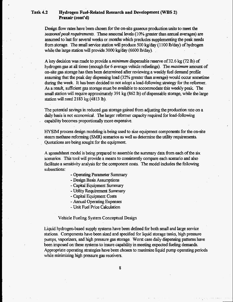
Design flow rates have been chosen for the on-site gaseous production units to meet the seasomlpeak requirements. These seasonal levels (1 O?? greater than annual averages) are assumed to last for several weeks or months which precludes supplementing the peak needs from storage. The small service station will produce 500 kg/day (1 100 lb/day) of hydrogen while the large station will provide 3000 kdday (6600 lb/day).
A key decision was made to provide a minimum dispensable reserve of 32.6 kg (72 lb) of hydrogen gas at all times (enough for 6 average vehicle refbelings). The maximum amount of on-site gas storage has then been determined after reviewing a weekly fuel demand profile assuming that the peak day dispensing load (32% greater than average) would occur sometime during the week. It has been decided to not adopt a load-following strategy for the refbrmer. As a result, suflicient gas storage must be available to accommodate this weekly peak The small station will require approximately 391 kg (862 lb) of dispensable storage, while the large station will need 2 183 kg (48 13 lb).
The potential savings in reduced gas storage gained from adjusting the production rate on a daily basis is not economical. The larger reformer capacity required for load-following
. capability becomes proportionally more expensive.
HYSIM process design modeling is being used to s i e equipment components for the on-site steam methane reforming (SMR) scenarios as well as determine the utility requirements. Quotations are being sought for the equipment.
.
A spreadsheet model is being prepared to assemble the summary data fiom each of the six scenarios. This tool will provide a means to consistently compare each scenario and also facilitate a sensitivity analysis for the component costs. The model includes the following subsections:
- Operating Parameter Summary - Design Basis Assumptions - Capital Equipment Summary - Utility Requirement Summary - Capital Equipment Costs - Annual Operating Expenses - Unit Fuel Price Calculation
Vehicle Fueling System Conceptual Design
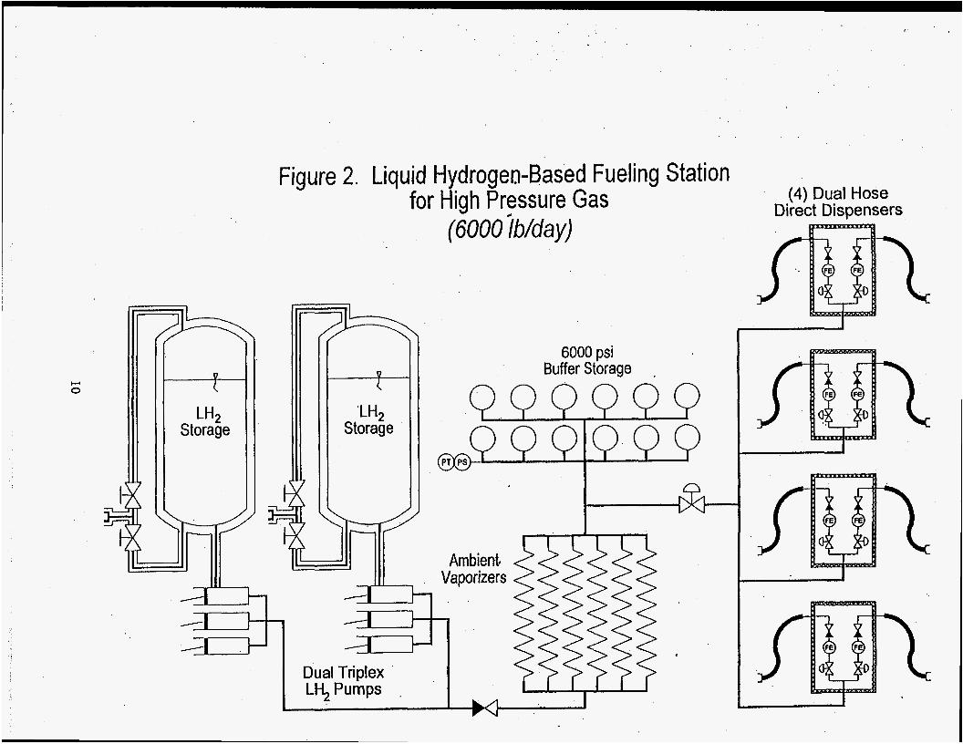
Liquid hydrogen-based supply systems have been defined for both small and large service stations. Components have been S i and s p d e d for liquid storage tanks, high pressure pumps, vaporizers, and high pressure gas storage. Worst case daily dispensing patterns have been imposed on these systems to insure capability in meeting expected fbeling demands. Appropriate operating strategies have been chosen to maximize liquid pump operating periods while minimizing high pressure gas receivers.
8
Task 4.2 Hydrogen Fuel-Related Research and Development (WBS 2) Praxair (cont’d)
Flow schematic drawings have been prepared for these options. As an example, Figure 2 presents the flow schematic for the large station design. Equipment costs are being collected for these systems and will be included in the Fuel Cost Model previously described.
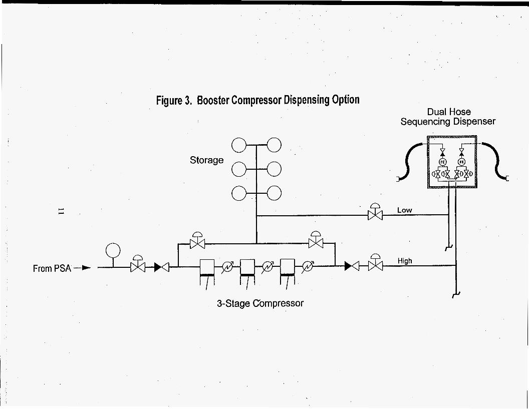
The gaseous hydrogen-based fieling system designs are nearing completion. A detailed evaluation was made comparing the cascade storage system (discussed in the last Quarterly Report) with a booster compressor storage and fbeling concept. The performance and costs of the cascade system were analyzed at three different storage pressure levels: 41.4,48.3, and 58.3 MPa (6000,7000, and 8460 psig). The optimal pressure level among these three choices was found to be 48.3 MPa (7000 psig) where a balance was struck between available dispensing volume and unit cost of storage.
However, the booster compressor concept shown in Figure 3 provides a substantial reduction (-50%) in storage costs. Greater storage recovery efficiencies can be achieved (90% vs. 52%), lower pressure storage can be utilized (24.8 MPa or 3600 psig), and larger water volume receivers result in lower unit costs. Figure 3 also presents a concept whereby a single compressor could serve the dual purpose of both storing gas and boosting pressure to fill vehicle tanks to 34.5 MPa (5000 psig). It is unclear yet whether there is a machine available on the market which can provide the flexibility needed for both functions. If not, two separate compressors could be used to achieve the same results.
Dispensing hardware for the vehicle fbehg stations would be extensions of what is being developed today for the natural gas vehicle market. Discussions with equipment vendors regarding the suitability of their hardware for hydrogen service and higher service pressures has not met with great concern. Metering issues would most likely be simplified with pure hydrogen as opposed to varying natural gas compositions both seasonally and geographically. Preliminary analysis of fill termination issues indicates that achieving accurate hydrogen fills may be less problematic than natural gas fbeling.
Hydrogen Vehicle Safety Analysis
There has been limited activity on this task during the quarter. Further review of NGV fbeling station designs and safety approaches has begun. Vehicle heling connector designs will be reviewed.
Final Report
A dr& of the section covering the task on Vehicle Fueling System Designs is nearing completion.
9
c, 0
Storage T
Figure 2. Liquid Hydrogen-Based Fueling Station for High Pressure Gas
Task 4.2 Hydrogen Fuel-Related Research and Development (WBS 2) Air Products (cont’d)
The following tasks were completed by Air Products and Chemicals (Air Products):
Air Products will study various production, storage, and distribution systems, to supply individual fbeling stations with hydrogen fbel, and evaluate the economics of the most practical options. The study will be conducted in stages: a screening of hydrogen production, storage, and distribution alternatives followed by economic evaluation of multiple hydrogen supply scenarios. The following five scenarios will be developed:
Scenario 1: Large remote natural gas steam - methane reformer ( S M R ) plants (30 and 300 tons/day hydrogen capacity) supplying liquid hydrogen to between 10 - 100 large heling stations capable of handling 500 vehicles per day each.
Scenario 2: Large local SMR plant with pressure swing adsorption (PSA) clean up (30 and 300 tons/day hydrogen capacity) supplying gaseous hydrogen via pipeline to the same market profile as above.
Scenario 3: On-site natural gas SMR plant (3 tondday hydrogen capacity) supplying gaseous hydrogen to a single large fueling station capable of handling between 83 - 500 cardday.
Scenario 4: The same as scenario 3, but using on-site partial oxidation of heavy hydrocarbons as the production method.
Scenario 5: Water electrolysis at a home garage (6 Ib./day hydrogen capacity) to supply compressed hydrogen to fbel 1 car/day.
Air Products will also conduct a safety analysis of all aspects of hydrogen distribution, dispensing, and onboard storage, and provide advice on onboard hydrogen storage techniques. Additionally, Air Products will evaluate the possible impact of hture technologies and will also develop recommendations for fbture work in consultation with Ford.
Hydrogen Infrastructure Study
Analyses of Scenarios 1,2, and 3 were completed and drafts were submitted to Directed Technologies, Inc. @TI) for comment.
12
Task 4.2 Hydrogen Fuel-Related Research and Development (WBS 2) Air Products (cont’d)
Scenario 1, Remote Natural Gas Reformation. PSA Clean-up. Hydrogen Liquefier Single Large Stations 30 & 300 TPD:
The wholesale price of hydrogen from a 30 tpd liquid hydrogen natural gas reformation plant as delivered to a customer vehicle would be $1.59/lb ($24.66/GJ) at a 10% after tax real rate of return. The hydrogen would be dispensed as a 5000 psig gas from multiple 3 tpd stations, an average distance of 500 miles from the production facility. The expected investment would be $71,000,000. .
The wholesale price of hydrogen from a larger 300 tpd Liquid Hydrogen Natural Gas Reformation plant would be $1.08/lb. The expected investment would be $283,000,000.
Scenario 2, Local Natural Gas Reformation. PSA Clean-up. Gaseous Hydrogen Pipeline Single Large Stations 30 & 300 TPD:
The wholesale price of pipeline hydrogen from a 30 tpd natural gas reformation plant as delivered to a customer vehicle would be $1.3 5Ab ($20.92/GJ) at a 10% after tax real rate of return. The hydrogen would be dispensed as a 5000 psig gas from multiple 3 tpd stations connect by a 30 mile long pipeline. The expected investment would be $85,000,000.
The wholesale price of hydrogen from a larger 300 tpd Natural Gas Reformation plant would be $1.16/lb. The expected investment would be $699,000,000.
Scenario 3,On-site Natural Gas Reformation. PSA Clean-up. Gaseous Hydrogen Compression. Single Large Stations 3 TPD:
The wholesale price of hydrogen from a 3 tpd liquid hydrogen natural gas reformation plant as delivered to a customer vehicle would be $1.68/lb ($26.13/GJ) at a 10% after tax real rate of return. The hydrogen would be dispensed as a 5000 psig gas from a single 3 tpd station located at the site of the production facility. The expected investment would be $10,200,000.
Hauled in liquid hydrogen would be competitive and would likely be used for peak demand periods or to provide hydrogen when the production facility was out-of-service for maintenance or catalyst change-out.
13
Task 4.2 Hydrogen Fuel-Related Research and Development (WBS 2) Air Products (cont'd)
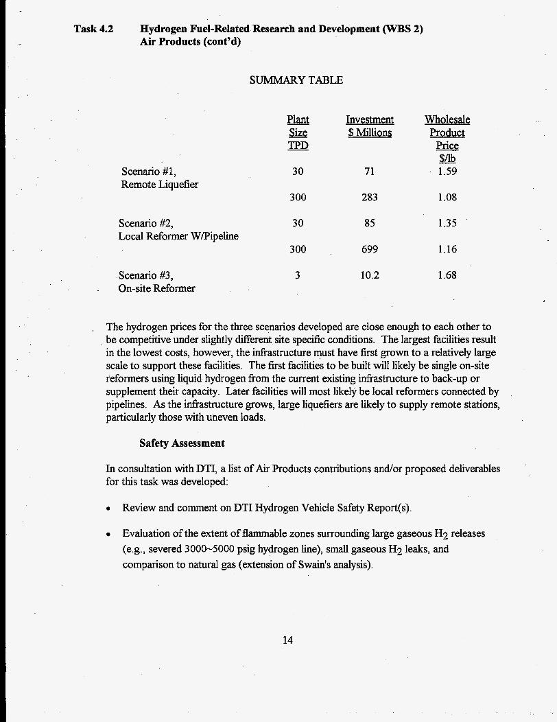
SUMMARY TABLE
Scenario #1, Remote Liquefier
Scenario #2, Local Reformer W/Pipeline
Scenario #3, . On-site Reformer
Plant &e TpD
30
300
30
300
3
Investment $ Millions
71
283
85
699
10.2
Wholesale Product
Price $/lb
. 1.59
1.08
1.35
1.16
1.68
. The hydrogen prices for the three scenarios developed are close enough to each other to be competitive under slightly different site specific conditions. The largest facilities result in the lowest costs, however, the infiastructure must have first grown to a relatively large scale to support these facilities. The first facilities to be built will likely be single on-site reformers using liquid hydrogen fiom the current existing infrastructure to back-up or supplement their capacity. Later facilities will most likely be local reformers connected by pipelines. As the infrastructure grows, large liquefiers are likely to supply remote stations, particularly those with uneven loads.
Safety Assessment
In consultation with DTI, a list of Air Products contributions and/or proposed deliverables for this task was developed:
0 Review and comment on DTI Hydrogen Vehicle Safety Report(s).
Evaluation of the extent of flammable zones surrounding large gaseous H2 releases (e.g., severed 3000-5000 psig hydrogen line), small gaseous H2 leaks, and comparison to natural gas (extension of Swain's analysis).
14
Task 4.2
0
' 0
0
0
0
Hydrogen Fuel-Related Research and Development (WBS 2) Air Products (cont'd)
Evaluation of the extent of flammable zones resulting fiom a liquid H2 line failure on a he1 station tank.
List of information needs which are generally related to vehicle configuration. Included are H2 storage vs. H2 use areas, types of piping proposed, machinery (H2 expanders, air blowers), available venting locations, etc.
List of safety considerations for the vehicle and the fuel station stressing inherent safety. For the vehicle this will include minimization of venting of H2. .
List of the types of small piping joints and valves (manual, automatic, pressure let down, etc.) that have been successfully used in Air Products' hydrogen systems (plants, gaseous hydrogen (GH2) trailers, liquid hydrogen (LH2) trailers, customer stations, etc.)
Failure rate (probability or frequency) data for vessels and piping components. This includes: burst failure, shut-off valve leakage, check valve leakage.
Application of quantified risk assessment (QRA) to H2 releases for both the vehicle and the fuel station systems, once these systems are better defined.
A report titled %igh Pressure Jet Releases fiom an Onboard Hydrogen Storage System", that examines the extent of the flammable zone resulting from a high pressure hydrogen leak, was submitted to DTI. Such a leak might occur fiom a small 5,000 psig fuel line which is severed during a vehicle accident. If an excess flow or inertia activated solenoid valve fails to function, the high pressure storage tank will empty-out.
Two different cases were evaluated, namely vertical release and horizontal release. The releases were assumed to occur from a height of 2 ft. above the ground, with the vehicle stationary, and with no equipment to impede the flow. The severed line sizes ranged fiom 1/16" to 1/4" in diameter.
Briefly, it was found that:
0 The area of the flammable mixture increases with the line size and with the storage pressure.
0 Buoyancy provides only a modest benefit in reducing the flammable area near the ground.
0 Typical daytime weather conditions reduce the flammable area relative to night time conditions. The major benefit is the increased wind speeds during day time.
15
Task 4.2 Hydrogen Fuel-Related Research and Development (WBS 2) Air Products (cont’d)
A comparison of flammable areas was made with similar line releases fiom a natural gas vehicle storage system at 3,000 psig. Natural gas would require larger line sizes to supply an internal combustion engine. Nevertheless, for equal 3,000 psig release pressures, hydrogen produced significantly larger flammable areas than did natural gas. One factor for this increased area is the very high sonic jet velocity for hydrogen - about three times that of natural gas.
The following tasks were completed by Lawrence Livermore National Laboratory (LLNL), ED0 Fiber Science (EDO), and Aero Tec Laboratories, Inc. (ATL):
A summary of work planned was presented to Ford in April and outlined lightweight pressure vessel developments to date (outside of this program), and other related capabilities of the three organizations (LLNL, EDO, and ATL). The Tank Performance Factor (burst pressure * internal volume / tank weight) for this technology (initiated by LLNL) is expected to be -5.0-5.5 million cm (-2.0-2.2 million in.) using T- 1000 carbon fiber (-3.0-3.5 million cm using T-700 fiber). The best alternative carbon fiber composite tank designs without LLNL technology are -3 .O-3.5 million cm using T- 1000 graphite fiber (currently a factor of -5 more expensive than T-700). Tanks can be designed to withstand a variety of non-pressure related loads if desired for added safety. They can be packaged into vehicles more easily because weight and volume penalties associated with dividing tanks into multiple units are reduced using LLNL technology.
In order to achieve the highest performance factor (lightest weight) vessels projected by this technology, a thin-walled liier is required throughout the entire surface area of the vessel, the highest strength-to-weight carbon fiber (e.g., T-1000) is required, the lightest weight boss (e.g., aluminum with a narrow bore) is required, and other safety/design features need to be ignored. For the purposes of this program we have chosen to consider: a variety of safety/design features, heavier bosses which enable quick fills and which are compatible with valves that may be selected with safety as the chief criterion (instead of weight), the use of less expensive fibers (e.g., T-700), and the use of thicker end domes. The use of thicker end domes will enable us to design, fabricate, and test the key components of this technology, while staying within the cost and time constraints of the program. In short, we expect to advance the state-of-the-art in pressure vessel technology, while agreeing to deliver operational hardware for testing in Phase 111 of this DOE/Ford program.
16
. . , . ~ .. - ~ j . . , ~. . ~ . . ,. .
Task 4.2 Hydrogen Fuel-Related Research and Development (WBS 2) LLNL/EDO/ATL (cont'd)
Develop Bladder-Lined Tank Fabrication Method
LLNL, ATL, and ED0 have designed and revised a series of prehminary tests to address the challenge of bonding the cylindrical portion of the bladder material to rigid end domes. A low density polyethylene (LDPE) carboy was procured, cut into samples, and used for trial seams to the'silver coated laminate by ATL. After testing a variety of seam methods and conditions, successfid bonding from the -0.01 cm (-0.004 in.) thick laminate to the -0.48 cm (-3/16 in.) thick LDPE was achieved. Samples of the bonded material are being sent to LLNL for evaluation. Orders have been submitted for samples of the specific resin used to manufacture the LDPE carboys for use in the end domes and samples of the specific resin used for the outer layer of our silver coated laminate for use in the end domes, if desired. Both resins need to be ground under cryogenic conditions to form powders for rotomolding (the method to be used for fabricating the thick LDPE end domes). ED0 has contracted with Rotational Molding of Utah to fabricate thick LDPE end domes to the specifications agreed on by LLNL, ATL, and EDO. Rotational Molding of Utah has a supplier of LDPE powders, but is willing to work with alternative LDPE powders if necessary. Delivery of LDPE end domes should commence in early August. A number of methods for lightweighting the end domes are being examined.
Preliminary measurements of the silver coated laminate material using the American Society for Testing and Materials (ASTM) permeability test rig at LLNL show comparable permeability rates to measurements -2 years ago and consistency between samples. Permeability measurements can be performed at room temperature h1l0 C (*20° F). This may be adequate to see temperature effects since permeability varies exponentially with temperature. Permeability measurements at larger temperature ranges or at pressures beyond a few atmospheres will be beyond the cost constraints of this program. LLNL has examined other lamination materials that would expand the operating temperature range of the pressure vessels and could enable higher curing temperatures of the composite with the bladder in place. LLNL has obtained samples of one alternate material fiom a vendor and has performed proof-of-principle experiments with ATL. Although significant work with alternate lamination materials is beyond the scope of this program, it may be of interest to other sponsors and may provide a superior design for DOEEord.
Metal Boss Design
A boss integration procedure has been designed which involves encapsulating a metal flanged boss into a molded end dome. The boss incorporates a capture feature which will lock it into the composite overwrap. The boss also incorporates a wrench flat to backup external plumbing connections. The possibility of using an internally located valve, such as a derivative of the series 1700 solenoid operated CNG (compressed natural gas) cylinder valve fiom Superior Valve Company is being examined.
17
Task 4.2 Hydrogen Fuel-Related Research and Development (WBS 2) LLNL/EDO/ATL (cont'd)
Phase I Report
LLNL, EDO, and ATL have determined a baseline set of materials and fabrication procedures that can be used to attempt the fabrication of a first generation bladder-lined pressure vessel. The silver-coated mylar that is laminated with low density polyethylene (LDPE) to form the cylindrical section of the bladder will be used to seam it to rigid LDPE end domes. The end domes will have an integrated boss and will be formed by rotornolding. M e r attaching the bladder to the end domes, it will be used as an inflatable mandrel for the carbon fiber epoxy overwrap. A low temperature curing cycle will be specified that is compatible with the bladder materials and the DOELFord operating temperature range of -40' C to +60° C (-40 F to +140° F).
Phase I Program Management
Multiple conference calls, faxes, and overnight mailing of samples and test results has been adequate to provide effective communication between the three organizations.
Baseline Pressure Vessel Design, Analysis, and Trade Study
ED0 and LLNL have commenced the evaluation of various epoxies and curing schedules that will be compatible with the bladder materials and the DOE/Ford operating temperature range. LLNL, EDO, and ATL are examining a number of methods for lightweighting the end domes.
Sealing and End Cap Design
LLNL, ATL, and ED0 have performed a preliminary design of a -30.5 cm (-12 in.) diameter bladder end cap for production by ED0 with rotomolding to be performed by Rotational Molding of Utah. ATL has successllly formed trial seals between the thin laminate and thick LDPE carboy.
Metal Boss Design and Fabrication
The challenges associated with the design of a boss for use with a thin end dome liner are being considered. However, under the scope of this program, the design will probably be limited to thick end domes. The possibility of using an internally located valve, such as a derivative of the series 1700 solenoid operated CNG (compressed natural gas) cylinder valve fi-om Superior Valve Company is being examined.
Phase I1 Program Management Tasks
Multiple conference calls, faxes, and overnight mailing of samples and test results has been adequate to provide effective communication between the three organizations.
18
Task 4.2 Hydrogen Fuel-Related Research and Development (WBS 2) LLNL/EDO/ATL (cont’d)
Material Fabrication and Test
LLNL, EDO, and ATL are considering various options for the design of the thin composite layer and adhesive that will contact the bladder. Sample fabrication is about to commence.
Subscale Prototype Vessel Fabrication and Test
Subscale prototype vessel fabrication has been initiated by placing the order for end domes with Rotational Molding of Utah.
The following tasks were completed by The Electrolyser Corporation, Ltd. (Electrolyser):
The purpose of this project is to investigate the technical feasibility, safety and cost of an electrolyhc hydrogen &el inhstructure for the Ford Fuel Cell Electric Vehicle. The project includes a cost analysis for a range of vehicle filling systems based on electrolytic hydrogen supply.
Systems Analysis
For the system task, information is being gathered on the different electrolysis processes. In the near term (next twenty years), it appears that two of these processes could play a role in large-scale electrolytic hydrogen production: liquid alkaline @OH) electrolysis and the solid polymer electrolyte (SPE) process. From preliminary process analysis, it seems that the SPE process may be suitable to small filling stations but is limited in scaling up to large plants due to the heat generated in the cells.
The costing analysis has focused on costing larger units based on the liquid KOH process using a plant cost range set by Electrolyser‘s current EI-250 technology and the estimated unit costs for an advanced design of alkaline electrolyser, which is currently under development and will be available in 5 years. Electrolyser’ s cost estimates indicate that the advanced alkaline technology, which could reduce costs by a factor of two fkom current levels, could be competitive with a large-scale steam reformer plant.
Safety Report
A written summary of comments were sent to DTI regarding the Preliminary Safety Report. A systematic failure mode analysis of the two filling station systems, commercial and home, was started.
Trends in the Hydrogen Market
A meeting was held with the Japanese WE-NET delegation to discuss global sourcing of hydrogen.
19
Task 4.2 Hydrogen Fuel-Related Research and Development (WBS 2) Electrolyser (cont'd)
Project Management
AProgram Management Plan was drW and submitted to Ford.
The following tasks were completed by BOC Gases (BOC):
Pathway 1 - 60 TPD Steam Methane Reforming ( S M R ) and Liquefier Option
A literature survey and patent search has been started to determine current state-of-the-art for large hydrogen liquefiers for the purpose of selecting which of several process cycle options to consider.
After the feed stream cost, the cost of liquid hydrogen fuel is strongly affected by the efficiency and capital cost of the liquefaction plant. Current hydrogen liquefaction plants are based on the Claude cycle and utilize reciprocating compression machinery for main feed and recycle compressors. This is because hydrogen's molecular weight is very low (2.02) and a large number of stages would be required for centrifugal compressors in this
. service. As the size of the liquefaction plant increases (>30 tpd) multiple large reciprocating compressors are required with no economy of scale. If practical ways of utilizing centrifugal compression machinery can be developed for large hydrogen liquefaction plants, then many benefits could be realized in addition to economies of scale. Work done by Union Carbide in the late 70's (US Pat. 3,992,167, Beddomne) presented an approach for the utilization of centrifugal compression machinery for very large liquefaction plants based on mixing propane with hydrogen to increase the molecular weight of the gas.
,
An objective of Pathway 1 will be to determine whether this scheme is practical for a plant as small as 60 tpd.
Pathway 2 - 11.5 TPD and 0.2 TPD SMR Options
Most of the work carried out for this option has been to concentrate on plant size vs. gaseous storage evaluations since this is critical to the overall scheme design and economics. A spreadsheet has been developed to look at the power and capital required to meet the fluctuating demand pattern with different plant sizes, storage volumes and pressures. All work has been focused on the 1.5 tpd option and once this has been evaluated, similar work will be done for the 0.2 tpd option.
20
~
Task 4.2 Hydrogen Fuel-Related Research and Development (WBS 2) BOC Gases (cont'd)
For the evaluation, the storage pressure has been varied between 5250 psi and 10,000 psi. Initial assessments have been for storage vessel sizes have been based on 4 inch diameter and 20 R long vessels Initial indications are that the higher storage pressure is attractive and the costs appear to be less even though the pressure is higher. To complete the analysis, however, the compression costs and powers are required as these could clearly have a significant impact on the final selection.
The cost of storage and compression is a significant element of the total cost. There may be a case for minimizing it and utilizing a larger steam methane reformer.
No work was planned or carried out on this task during the current reporting period. However the work on the plant size vs. gaseous storage taking part in the Pathway 2 task will be very similar for this task with only the reformer specifications differing.
Liquid Storage and Filling System
The work carried out this period was a review of the design basis and development of a list of design basis assumptions to cover items which did not appear in the DTI design basis document.
Task 4.3 Lightweight Fuel Cell Research and Development (WBS 3)
May 23, 1995 was the effective award date for the subcontracts to both Thermo Power Corporation, Tecogen Division (Tecogen) and Mechanical Technology, Inc. (MTI).
The following tasks were completed by H Power Corporation (H Power):
System Design
The computerized heat and mass balance program was used to finalize the cell and stack design.
Drawings
The detail design of the cell's molded carbon separators was completed. The preform mold was procured, installed and is operational.
21
- _ . . .. . . . .
. :
Task 4.3 Lightweight Fuel Cell Research and Development (WBS 3) H-Pow er (con t' d)
Single-cell Testing
The single-cell hardware; which mimics, at 1/20 ft2 size, the real hardware; was designed and quotes received. Procurement of the hardware is in progress. The testing of H Power's "standard" electrodes will be performed in the new hardware.
Modeling
A mock-up of the stack was constructed and checked. One error was discovered and corrected.
ProcurementIFabrication
Drawings for the stack hardware were sent to potential vendors for price quotes. Initial molding trials, using the recently procured preform mold, were started.
Documentation
The drawings for the stack were completed and copied for submission to vendors for quotes.
Other
For the molding of the cell separators, a compression press was designed, procured and installed at H Power's.facility in New Jersey. Test parts were fabricated.
The following tasks were completed by Energy Partners, Inc. (Energy Partners):
Energy Partners has already developed and successfidly tested several large active area multi-cell stacks. However, during the previous reporting period, the three main areas of concern as follows:
a) Performance improvements b) Reduction of platinum loading c) Stack design and weight reduction.
Performance Improvements
Energy Partners' he1 cells with Nafion 1 15 membranes (the only commercially available brand) exhibit very early departure from a "quasi-linear" region in a polarization curve for hydrogen/& operation. In addition, very high air flows (corresponding to the stoichiometric ratios of 3.5 and higher) are needed to maintain this performance. Figure 1 shows a polarization curve for the best performing cell in a multi-cell stack.
22
Task 4.3 Lightweight Fuel Cell Research and Development (WBS 3) Energy Partners (cont’d)
1 .I 1
9 On9 - 0.8 - 9 0.7 - - 0.6
0.5
Q) cl)
0 > Q) 0
0.4 0.3
0 100 200 300 400 500 600 700 800 900 1000 current density (mNcmY)
Figure 1 Energy Partners he1 cell performance
A search for improvements has been diversified in several directions, such as optimization of the flow field, study of resistive losses in he1 cell hardware, testing of various membranes and membrane/electrode assemblies, and most recently a study of diffusion problems in a backing layer or at the interface between backing and catalyst layers.
Flow Field Analysis
Energy Partners’ analysis of the flow field indicated that larger manifolds at cell inlet and outlet are needed, as well as wider flow channels. The current design of the air flow field includes two inlet and two outlet manifolds, with a 0.066 cm2 cross sectional area each. The enlarged inlet and outlet manifolds have been machined on the air side of a collector plate. This plate was then assembled in a single cell stack and tested in operation. The test did not show any improvement in performance.
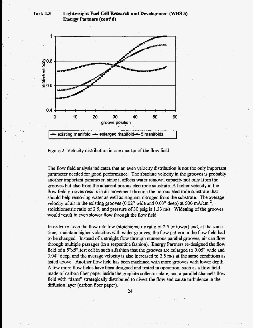
A finite element analysis of the flow field has shown that enlarged manifolds provided slightly better velocity distribution in the flow field grooves. The pressure drop in the manifolds has been reduced sigruficantly. However, in order to get more even flow distribution through the flow field, the number of manifolds has to be increased. Figure 2 shows velocity distribution in onequarter-of the- flow field for three different scenarios, namely (i) existing manifolds, (ii) enlarged manifolds, and (iii) five enlarged manifolds.
23
- , . .. _. ... . - ...I_-
Task 4.3
1
E0.8
? ’
20.6
0 0 Q
Q > m
- .- c -
Lightweight Fuel Cell Research and Development (WBS 3) Energy Partners (cont’d)
0.4 ! I I I I I I I I I I
0 10 20 30 40 groove position
50 60 .
~ ~~
w a n i f o l d + enlarged manifold+ 5 manifolds I
Figure 2 Velocity distribution in one quarter of the flow field
The flow field analysis indicates that an even velocity distribution is not the only important parameter needed for good performance. The absolute velocity in the grooves is probably another important parameter, since it affects water removal capacity not only fiom the grooves but also fiom the adjacent porous electrode substrate. A higher velocity in the flow field grooves results in air movement through the porous electrode substrate that should help removing water as well as stagnant nitrogen fiom the substrate. The average velocity of air in the existing grooves (0.02” wide and 0.03” deep) at 500 mA/cm ’, stoichiometric ratio of 2.5, and pressure of 30 psig is 1.33 d s . Widening of the grooves would result in even slower flow through the flow field.
In order to keep the flow rate low (stoichiometric ratio of 2.5 or lower) and, at the same time, maintain higher velocities with wider grooves; the flow pattern in the flow field had to be changed. Instead of a straight flow through numerous parallel grooves, air can flow through multiple passages (in a serpentine fashion). Energy Partners re-designed the flow field of a 5”xS’ test cell in such a fashion that the grooves are enlarged to 0.05” wide and 0.04” deep, and the average velocity is also increased to 2.5 m/s at the same conditions as listed above. Another flow field has been machined with more grooves with lower depth. A few more flow fields have been designed and tested in operation, such as a flow field made of carbon fiber paper inside the graphite collector plate, and a parallel channels flow field with “dams” strategically distributed to divert the flow and cause turbulence in the difksion layer (carbon fiber paper).
24
Task 4.3 Lightweight Fuel Cell Research and Development (WBS 3) Energy Partners (cont'd)
All of the above depicted flow fields have been tested in 160 cm2 single cell test fixture and/or in 780 cm2 multi-cell stack. So far, none of the tested flow fields resulted in expected performance improvements in hydrogedair operation, which indicates that a flow field might not be the major reason for poor air performance.
Flow Rate - Stoichiometric Ratio
Stoichiometric ratio is a very important parameter in fuel cell design and operation. Usually, the air flows corresponding to a stoichiometric ratio of 2 to 3 are used in PEM fuel cells. A higher ratio results in higher oxygen concentration throughout the cell, as shown in Figure 3. However, a higher ratio (higher air flow rates) results in higher compressor capacity and higher pressure drop through the stack and piping system, thus increasing the hotel load.
c.' 'si Q) r a
0 B
0.2
0.15
0.1
0.05
0 0 2 4 6 8 10
stoichiometric ratio
Figure 3 Oxygen exit concentration as a function of stoichiometric ratio
Resistance Measurements
Resistive losses, both electronic resistance in cell hardware and ionic resistance in membrane can significantly impair the fuel cell performance. Energy Partners has calculated and experimentally verified the resistance of the fuel cell hardware. The resistance of two electrodes and two halves of the collector plate, including the contact resistances, is found to be 0.02 &m2. This corresponds to 10 mV voltage drop at 500 mA/cm2. The resistance in membrane is much higher, particularly ifthe membrane is not well humidified.
25
Task 4.3 Lightweight Fuel Cell Research and Development (WBS 3) Energy Partners (cont’d)
Testing of Various Electrodes and Membranes
In addition to Energy Partners’ standard electrodes used in conjunction with Nafion 1 15 membrane, several other experimental membrane electrode assemblies, prepared in-house or acquired from vendors (such as BCS Technologies, and W.L. Gore & Associates) have been tested. BCS Technologies claims that their MEA does not need any humidification; however we have not been able to replicate their perfomance in our hardware. Particularly interesting are the Goreselect membrane and the GoreCarbel membrane electrode assembly because they are made of a very thin (about 20 pm) composite material. This material has very good mechanical properties and much lower resistance than Nafion. The H2/02 performance was up to expectations, but the Hdair performance exhibited the same features as all the other configurations we tested. These tests may help in identifjmg the causes of poor air performance.
Reduction in Platinum Loading
Energy Partners makes the electrodes with heavy loaded Platinum black (4 mg/cm2). . Commercially available electrodes by E-TEK, Inc., Natick, MA, with 20% Pt supported
on Carbon, have a standard platinum loading of 0.35-0.4 mg/cm2.
. Researchers at the Texas A&M University’s Center for Electrochemical Studies and Hydrogen Research and Los Alamos National Lab have demonstrated electrodes for PEM fuel cells with ultra-low Pt loading (<0.05 mg Pt/cm2).
PSIT of Andover, MA, is developing a novel electrochemical catalyzation (ECC) technique to prepare high utilization carbon-supported PEM electrodes with as low as 0.05 mg Pt/cm2. Energy Partners has delivered a single cell standard stack (780 cm2) to PSIT for testing of their electrodes in realistic environment. Lately, Energy Partners delivered more hardware that enabled PSIT to assemble a multi-cell stack.
PSIT has run a cell prepared with their ECC anode (0.05 mg/cm2, Energy Partners’ standard cathode (4 mg/cm2) and Nafion 115 membrane. The cell exhibited stable performance over the life of the test averaging approximately 0.7 V at 300 amps per square foot (ASF) (323 mA/cm2) in Hd02 operation at 40 psig and 55” C. In H2/Air operation, only 250 ASF ( 269 mNcm2) at 0.6 V, 40 psig and 55°C was achieved. When the cell was reversed, i.e., the low loaded ECC electrode was on the cathode side, the performance was even worse. Such a cell demonstrated a 100 mV performance deficit at 300 ASF in hydrogerdoxygen operation when compared to the previous test when the ultra-low loaded electrode was used as an anode and a high loaded electrode as a cathode (Figure 4). The air performance was poor, typical of a damaged or unoptimized electrode structure. Nevertheless, these results are encouraging when combined with the earlier reported data because operation with an ultra-low platinum loading has now been demonstrated on both the anode and the cathode, which corresponds to cell loading of 0.1 mg Pt/cm2.
26
Task 4.3 Lightweight Fuel cell Research and Development (WBS 3) Energy Partners (cont'd)
Improvements are needed in electrode structure so that satisfactory performance is achieved in hydrogenlair operation as well. If necessary, a slightly higher platinum may be used, that would still be well below the program goal of 0.25 mg Pt/cm2.
1
0.8
.c m .- c c. z 0.6 0 Q
loading
0.2 0 100 200 300 400
current density (ASF) 500 600
Figure 4 Polarization curves for various cell configurations test fixture: EP single cell
Energy Partners has re-designed and machined the stack end-plate. The new end-plate weighs 15.3 lb., which is a reduction of over 40%. A stack with the new reduced-weight end-plates has been assembled and tested in operation; the performance has not been affected.
27
Task 4.3 Lightweight Fuel Cell Research and Development (WBS 3) Energy Partners (cont’d)
Energy Partners’ current stack design includes an internal humidification section for both anode and cathode inlet streams The humidification water loop is coupled with a cooling water loop inside the stack. This configuration does not provide for any regulation of the reactant gases humidity. Therefore, an option is to remove the internal humidification section fiom the stack. This would also result in about 10% weight savings.
An analysis of flows and velocities in inlet manifolds has begun. Initial calculations indicate that the oxidant manifolds and headers in current Energy Partners stack design are not big enough for the flows that will be required for 10 kW (650 slpm). Solutions are being sought.
Stack configuration, i.e., cell size, number of cells, manifold size, number of manifolds and their position, depends on the result of the flow field analysis and selected membrane/electrode assembly and its performance. Nevertheless, preparations for re- designing the stack have begun. Figure 5 shows conceptual reactants flow pathways through the stack for the options being considered.
m active cells humidification ,
cells active cells I I
Figure 5 Reactants flow pathway through the stack; a) with internal humidification, and
b) without humidification
A 50-cell stack without humidification section and with reduced-weight end plates is estimated to weigh less than 160 lb., which is more than 20% weight saving as compared with the current Energy Partners stack design.
The following tasks were completed by International Fuel Cells (IFC):
Materials Purchasing
The materials purchasing task was established to acquire critical long lead-time materials required for execution of the program. An initial review of the materials required for the program identified thin membrane and electrode catalyst as the critical long lead time materials. All other materials identified did not require long lead times for ordering or were available at IFC.
28
Task 4.3 Lightweight Fuel Cell Research and Development (WBS 3) IFC (cont'd)
The thin membrane material was ordered at the outset of the program and was available at IFC on April 17, 1995. In late April, after review of subscale test results carried out under earlier programs, the appropriate electrode catalyst was identified and a purchase order was issued for quantities sUacient for the first two quarters of the program. IFC plans to evaluate the reqLiirement for future catalyst purchases based on the yields demonstrated with this first lot of material. The first lot of material was received in June of 1995 and was available in time for single cell testing.
This task was concluded with the acquisition of both the membrane and catalyst materials.
Scale-up Low-Catalyst Loaded Cathode and Anode
The focus of this task was to take low platinum loaded PEM electrode catalyst technology developed under earlier programs and scale it to a cell size consistent with the program requirements. The chosen cell size was that used in IFC's earlier Unmanned Underwater Vehicle program. The active area for this cell is 0.278 square feet. The low platinum loaded electrode catalyst technology had been developed at 4.5 square inch cell active areas. The task was principally focused on scaling the electrode catalyst to 40 square inches.
At the outset of the program, FC's Technology Group was consulted on the incorporation of low loaded electrodes into this program. It was concluded that a scale-up version of low loaded electrode technology, developed under internal research and development (IR&D), was feasible. The technology group provided the procedure for electrode fabrication. . Single cell tests in the laboratory on cells made with electrodes based on this procedure had shown promising performance at low platinum loadings.
First, the full-scale and sub-scale thin substrate materials were prepared for use in the low-catalyst loaded electrode manufacturing trials in April of 1995. Those materials were to be used to qualify the low-catalyst loaded catalyst layer application techniques first at sub-scale and then at full-scale.
Next, the ingredients required to make the first full-scale, low-catalyst loaded electrodes were prepared. Enough material was prepared for a I11-scale single cell incorporating low-catalyst loaded electrodes. Subscale catalyzing trials were conducted per the low- catalyst loaded electrode formulation and procedure developed under FC's earlier internal research and development programs. This effort involved several trials to finalize the parameters in the catalyzing process to make uniform catalyst layers repeatably on the chosen substrate material.
29
Task 4.3 Lightweight Fuel Cell Research and Development (WBS 3) IFC (cont'd)
After completing the sub-scale catalyzing trials, the effort shifted to producing similar catalyst layers at full-scale (0.278 square feet active area). Again several trials were required to match the processing parameters to the 111-size substrate material and the full- sized catalyzing equipment. Some compromises were made in the fabrication procedures during the scale-up effort. At the completion of the effort, Ill-sized electrodes had been fabricated at 0.30-0.33 mg/cmZ platinum loading. Efforts to reduce the catalyst loading krther were postponed until satisfactory performance was demonstrated in a full-scale single cell test at these loadings under this task.
The testing task was concluded with the preparation of full-scale, the low platinum loaded electrodes.
Manufacture Dual Water Transport Plate Assemblies
The principle effort in this task was the design and manufacture of the dual water transport plate assemblies required for the first single cell test(s). The dual water transport plate is a unique bi-polar plate design that provides passive water removal on the cathode side of the cell as well as enhanced humidification on the anode side of the cell.
First, the prints required for the manufacture of dual water transport plate assemblies for the first single cell were prepared. Though these assemblies had been made and tested by IFC in earlier programs, their design had to be slightly modified to accommodate the thinner membrane being used under this program.
Then a single set of anode and cathode water transport plate assemblies were prepared per procedures developed in earlier PEM programs at IFC. The assemblies were successfully pressure tested to 53 psia and were made available for testing later.
This task concluded with the successful pressure test and delivery of the dual water transport plate assemblies to testing.
Prepare Test Facility for Single Cell Test
The work effort for this task centered on the preparation of the test stand required for short duration testing of single cells in IFC's component development laboratory. Laboratory testing was been adopted for this program to shorten development cycle times and minimize cost to the program.
30
Task 4.3 Lightweight Fuel Cell Research and Development (WBS 3) IFC (cont'd)
Much of the effort under this task focused on the preparation and calibration of reactant saturators required for the single cell test@). The saturators were prepared and installed in the test stand in a laboratory hood. After satisfactory pressure testing the saturators were calibrated to determine if they could provide sufficient reactant humidification over the desired cell operating envelope. The results of the reactant saturator calibration showed that they had sufficient saturation capability to cover the anticipated cell operating envelope without jeopardizing the single cell(s).
Another large segment of the effort under this task was the preparation of an electrical load system capable of operating over the anticipated range of cell performances. Initially, the availability of power supplies and load banks was reviewed. After selection of the appropriate equipment, the equipment was checked out and released to the laboratory. The necessary cabling and current shunt were also prepared. The completed electrical load system is capable of operating full-sized single cells and stacks at current densities up to 250 amperes.
This task was concluded with the satisfactory demonstration of electrical load system, the satisfactory calibration of the reactant saturators, and the satisfactory pressure testing of the associated test stand plumbing.
Test Low-Catalyst Loaded, Full-scale Single Cell(s) with Advanced Membrane
The primary focus here was the assembly and testing of low platinum loading, full-scale single cells with thin membranes. The electrodes prepared earlier were to be combined with the already prepared and tested dual water transport plate assemblies.
Initially, the advanced thin membrane, purchased early in the program (DuPont's Nafion@ NE-1 12), was processed in preparation for the first single cell. Sufficient material was prepared to allow for a number of single cell builds.
In May, the low-catalyst loaded electrodes prepared at 0.278 square foot active area, were edge impregnated and trimmed in preparation for lamination to the membrane. The platinum loadings for both anode and cathode electrodes were 0.30 - 0.33 mg/cm2. The subsequent lamination of these electrodes and the NE-1 12 membrane into a membrane electrode assembly (MEA) was successfbl.
A single cell with 0.278 square foot active area and 0.30 mg/cm2 Pt loading was assembled and successfully pressure tested in late May. A test plan was drafted and reviewed in early June. The draft test plan was reviewed and revised per comments of the Systems Analysis and Performance Group.
31
Task 4.3 Lightweight Fuel Cell Research and Development (WBS 3) IFC (cont'd)
After completion of the test plan and successful pressure testing, the cell was installed into the test facility. Initial performance of the single cell was dramatically lower than that expected. The cell was tested on hydrogen and air at both ambient and 30 psig. In both cases, performance was consistently low. Product water removal through the cathode and anode water transport plates appeared normal and no leakage was observed during the test.
IFC was performing a series of diagnostic tests to determine the cause of the low performance at the end of the reporting period. Additionally, the manufacturing and assembly procedures used to produce the membrane and electrode assembly for this single cell were being reviewed for discrepancies relative to earlier sub-scale cells. The output of the diagnostic tests and the procedural review will form the basis for a teardown plan for this single cell as well as a preliminary plan for the preparation of the next single cell for testing.
Prepare Components for Bill of Materials @OM) 4-Cell Stack
. The objective of this task is to prepare the necessary components for the a Bill-of-Material four-cell stack based on the most successful single cell design tested under the testing task. Since the design and function of the dual water transport plates required for the four-cell stack has been demonstrated in earlier programs, these components were prepared for the BOM four-cell stack during this quarter.
.
The following tasks were completed by Thermo Power Corporation, Tecogen Division (Tecogen):
This section of the report describes the work performed by Tecogen' and its subcontractor, Analytic Power Corporation. Under Phase I of this project, a 12 kW PEM fuel cell stack will be provided to Ford Motor Company which has been designed to meet the following performance goals:
Gross Power Output 12 kW Cell Voltage Current Density 800 ASF Power Density
0.6 volts or greater
8 1bkW net or less Stack Efficiency 47%
Phase I - Definition, Planning, Design, and Evaluation - consists of six (6) tasks. The work performed under each of these task during this reporting period is summarized below.
Tecogen is a division of Thermo Power Corporation, a Thermo Electron Company
32
Task 4.3 Lightweight Fuel Cell Research and Development (WBS 3) Tecogen (cont'd)
Cell Stack Design
Most of the work on the detailed design and analysis of the 12 kW PEM fbel cell stack was performed prior to the actual start of the contract on May 2, 1995. In addition, performance tests were conducted on a four-cell substack and sealing tests were conducted on a single cell mock-up to veri% the integrity of the sealing concept. The results of some of this work are summarized below.
The Phase I cell stack design and analysis is essentially complete. This includes the detailed computational fluid mechanics calculations performed to optimize the flow distribution within the cells.
Work on this task is currently focused on preparing of new four-cell substack, that incorporates the new sealing concept, for a performance verification and seal concept acceptance test and on upgrading the test stand.
RESULTS OF PEM FLUID FLOW STUDIES
Stack Flow Distribution
The stack flow distribution refers to the variation in the flow in the cathodes or anodes between cells in a stack. Ideally, all the cells in a stack would operate at the same voltage. In order to achieve this, all of the cells must receive roughly the same amount of flow. The flowfields of the cells are connected hydraulically in parallel in the stack by the inlet and exit manifolds. Since there are pressure drops in these manifolds, it is physically impossible for each cell to "see" the same pressure drop. To minimize variations in flow between cells, the pressure drop between the inlet and exit manifolds should be kept at least 10 times higher than the total pressure drop in the manifold.
This can be accomplished either by port control or field control. With port control the bulk of the pressure drop across the flowfield occurs in the inlet or exit (or both) port area. Usually this is an element with precisely machined grooves in it. The ports Erom cell to cell are made very consistent so that any variations in the pressure drop in the flowfield have little effect on the flow distribution. With field control, the pressure drop in the port is kept as low as possible and all of the pressure drop occurs within the flowfield itself.
Tecogen tried using both of these approaches in the stack designs during this program and found field control to be the most effective. Port control resulted in too high of a total pressure drop and tended to inhibit good distribution across the cell by limiting the gas velocities that could be generated. Field control does put an additional requirement on the flowfield element in that the pressure drop must be consistent fiom part to part.
33
Task 4.3 Lightweight Fuel Cell Research and Development (WBS 3) Tecogen (cont'd)
Cell Flow Distribution
The groove geometry in the flowfield is critical in determining how the reactant gas gets distributed over the active area of the cell. This distribution, in turn, has a dramatic effect on the overall cell performance. A cell with uniform reactant distribution will run well, while one with non-uniform distribution will tend to show poor performance -- particularly when there are inerts in the reactant streams. In order to determine the most effective geometries, the flow patterns using both Finite Element and Finite Difference techniques were examined.
FEA Analysis
The Algor FEA soRware was used to perform this analysis. Because of computer hardware limitations, there was an inability to apply this to flowfields with a large number of grooves. Figure I shows the velocity distribution for the original "2" flow flowfield pattern. This flow pattern was abandoned because at the time extensive flooding in the comers of the baffles was observed. The Algor flow distribution is felt of be accurate because it predicts the lowest velocities in the exact locations that flooding was observed.
Finite Difference Computer Model
Modeling Approach
When it became clear that the finite element approach to model flowfields with large numbers of grooves could not be used, a finite difference code was written. With this approach the flowfield is assumed to be flooded with water and therefore have a 0% porosity and the grooves are considered as a complex network of pipes.
A laminar fluid analysis code has been completed which uses a back-substitution technique to solve for the pressures at all the nodes in a flowfield with narrow grooves parallel to the flow direction and wider channels perpendicular to the flow (See Figure 2). The code allows the user to enter values for the diameter of the flowfield as well as the number of channels. In addition the inlet and exit pressure can be specified as well as the geometry of the grooves and channels (width and depth). At present, the code only considers laminar flow, and includes a routine that verifies that the maximum Reynolds number is less than 2000 before proceeding with the analysis. If this is not the case, the code automatically increases the exit pressure until the condition is satisfied. Data from the code includes pressures and flows at all the nodes and is in standard spreadsheet format readable by Lotus or Excel.
34
Task 4.3 Lightweight Fuel Cell Research and Development (WBS 3) Tecogen (cont'd)
Modeling Results
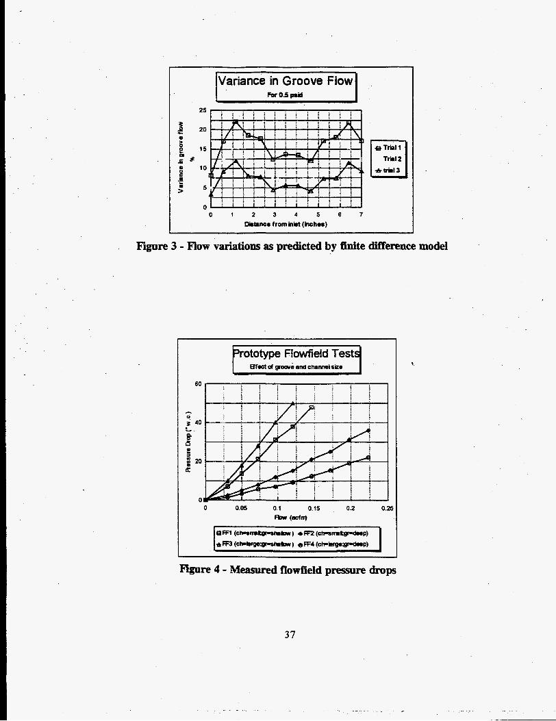
The objective in this modeling was to examine the effect of variations in the groove and channel dimensions on the flow distribution. Also important is the total flow through the flowfield and how this relates to an average cell oxygen utilization. Three trials were conducted using the finite difference model:
Trial I - Grooves: .010 wide x.020 deep. Channels: .040 wide x.030 deep Trial 2 - Grooves: .010 wide x.015 deep. Channels: .040 wide x.030 deep Trial 3 - Grooves: .010 wide x.015 deep. Channels: .050 wide x.030 deep
In each case, the inlet pressure was specified and fixed at 40 psig, the exit pressure to 39.5 psig, and the temperature was assumed constant at 180'F. The groove spacing (pitch) and channel spacing was kept constant for the trials. The grooves were spaced every .050" and parallel to the flow while the channels were spaced approximately every 1/2" and perpendicular to the grooves. This had the effect of dividing the flowfield up into 13 flow "sections." Since the flowfield is circular, the number of grooves in each section is different -- there are fewer grooves in sections close to the inlet while there are more grooves in sections in the center of the flowfield.
Figure 3 compares the variance in the flow between grooves located between common channels for the three trials. The highest variation occurs in grooves that are located from 1/2" to I - 1/2" from the inlet or exit sections. This is reasonable since it is in this area that the gas experiences the most significant change in direction. This is also where gas velocities are the highest and, as a result, where most of the pressure drop occurs. With a circular flowfield and a smaller cross-sectional area at the ports, the gas velocity will always be higher in this region. That is why in Figure 3 you see the same general pattern from case to case. The most significant result of the analysis is the drastic reduction in the % variation in the groove flow between Trial I and Trial 3. For a constant utilization, the variation in flow in the grooves will translate directly into a variation in the local current density.
The results in this area are in good agreement with those obtained by Dr. Eric Kalu at the University of South Carolina running a similarly structured code.
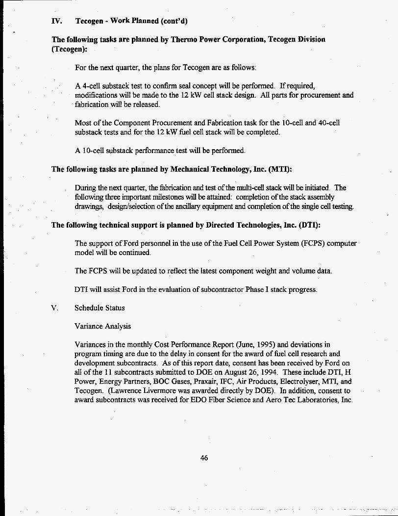
In addition to the flow distribution results, measurements were taken of the total pressure drop across the flowfields as a function of flow rate. The results of this testing are shown in Figure 4. From these measurements, a total pressure drop across the cathode of the stack of about 15-30" W.C. (0.5-1.0 psig ) is expected.
35
Figure 1 - "2" Flow Distribution
figure 2 - Field control flowfield geometry
36
[Variance in Groove Flow 1 1 For 0.5 p d I
25
z 2 20 e 6 g 15 .a Pap $ 10 *trial3 c
0 0 1 2 3 4 5 6 7
DhtPnce from inM (inch-)
Figore 3 - Flow variations as predicted by finite difference model
prototype Fiowfieid Test4
*re 4 - Measured flowfield pressure drops
37
. - . . . . . . . . . I - . . . . ..
.
Task 4.3 Lightweight Fuel Cell Research and Development (WBS 3) Tecogen (cont’d)
Four-Cell Substack Perfbrmance Test
Ultimately, the test of any flowfield design is its impact on stack performance. Once the groove and channel sizes were determined, a 4 cell substack was operated with the advanced field control flowfields. The tests were performed with hydrogen and air at 35 psig. Humidification was estimated to be 5-10% at the cathode and 100% at the anode.
The performance curve obtained fiom this testing is shown in Figure 5 . Note that the graph shows the average cell voltage. The cell voltage was approximately 0.7 volts at 800 ASF and 0.6 volts at 1000 ASF. Measurements during the testing showed that the cell voltage variation at 1000 ASF was about 50 mV. While single cells have achieved higher performance levels, this performance is the best to date on a mukiple-cell pressurized stack. These improved results were principally due to the improved flow field designs and a new membrane material.
Seal Configuration Test
A four-cell substack test is scheduled for the next quarter to confirm the integrity of the seal design concept with the cells operating at design pressure and temperature conditions. Preparations of the parts for this test are underway.
.
The seal configuration that will be used has been successfidly tested previously in a single cell mock-up where each of the potential leak paths was determined to be leak tight.
Test Stand Upgrade
The test stand is being upgraded with a new air compressor to increase its capacity to 12 kW and other moditications are being made to facilitate he1 cell stack testing. The new air compressor, for 12 kW operation, has been installed and checked out. Work on plumbing modification and signal conditioning is in progress.
38
r
35 psig WAir
1 -2
1 al ul lm
0.8 > - 8 0.6 d) - ul
Q) E 0.4
0.2 2
0 0 500 1000 1500 2000
Current Density (asf)
Figure 5 - Substack Performance with advanced flowfields
39
POWER
VOLTAGE
CELL VOLTAGE volts
CURRENT DENSITY
DIAMETER (ACTIVE)
DIAMETER (OUTER) 9.3 in
ACTIVE AREA I 31.9 I in2 -~ ~
FRAME AREA 35.3 in2
TOTAL AREA 67.2 in2
~
Task 4.3 Lightweight Fuel Cell Research and Development (WBS 3) Tecogen (cont’d)
12 kW PEM Fuel Cell Stack Design Characteristics
The design characteristics of the 12 kW PEM fuel cell stack that will be developed for delivery to Ford are summarized in the following table.
STACK LENGTH 21.4 in
STACK WEIGHT 65.7 lb
SPECIFIC WEIGHT (GROSS)
CELLS/COOLER 12 I CATALYST LOADING 0.2 mgm/cm2
Hz CONSUMPTION 6 scfm
AIR FLOW I 27 I scfm
Components ProcurementRabrication
Sources for some potentially long-lead items have been identified and purchase orders placed.
40
Task 4.3 Lightweight Fuel Cell Research and Development (WBS 3) MTI (cont’d)
Stack Specifications - Establish Design Operating Conditions and Cell Size
This task is complete.
Stack Assembly Drawings
Work on this task was initiated in parallel with the Stack Specifications task efforts and has continued at a rapid pace since its completion. A preliminary stack assembly design has now been completed and an internal review is plarmed €or the next reporting period.
DesigdSelect Ancillary Equipment
This task has progressed at a slower pace due to the emphasis on the longer lead tasks.
Single Cell Tests
Tests have proceeded with various humidification component designs. and an 8: 1 active: humidification cell ratio design point has been selected. Tests are now underway to select the bipolar plate component design.
The foIlowing technical support was provided by Directed Technologies, Inc. @TI):
Air Compression System Design
DTI continued the preliminary design of the air compression system with an emphasis on structural and aerodynamic features. Draft full scale l i e drawings of the integrated hydrogen expanderhr compression were prepared.
Fuel Cell System Component Sizing
Computations were made for the baseline fuel cell power requirements and fuel consumption rates for three classes of fuel cell vehicles (based on Aspire, Taurus, Econoline) to be used as a starting basis for detailed drive cycle simulations to be conducted by Ford. High pressure hydrogen storage tank volumes and weights for multi- tank configurations for various classes of automobiles were recomputed. DTI worked with Ford personnel to produce a simple tank weight and volume algorithm to be used in the vehicle design process.
Phase I Testing Plan
DTI has prepared and submitted a draft Phase I stack testing plan to Ford.
41
rn.
Iv,
Current Problems
The delay in consent for the award of he1 cell research and development subcontracts continued to affect program timing during this quarter.
Work Planned
Task 4.1 Conceptual Propulsion System Design (WBS 1)
Improved weight and volume density of he1 cell systems will be used to recalculate the power system requirements and packaging efforts.
Task 4.2 Hydrogen Fuel-Related Research and Development (WBS 2)
The following subtasks are planned by Directed Technologies, Inc. (DTI):
Subtask 4.2.1 Hydrogen Onboard Storage
The final Onboard Hydrogen Storage Report will be submitted. DTI will continue the oversight of the LLNL/EDO/ATL Tank research and development.
Subtask 4.2.2 Safety Issues
The final Accident History Assessment report will be submitted and The Hydrogen Vehicle Safety Report will continue to be updated.
Subtask 4.2.3 Hydrogen Infrastructure Studies
The subcontractor studies will be coordinated and the Infrastructure Study results will be evaluated.
The following tasks are planned by Praxair, Inc. (Praxair):
Work planned during this next quarter will be directed toward completing the Hydrogen ProductiodDistribution Options Evaluation and Vehicle Fueling System Conceptual Design tasks as well as halizhg the Inhistructure Fuel Cost Model spreadsheet.
Effort will then focus on the Hydrogen Vehicle Safety Analysis task as the above work is completed. Draft sections for the Final Report will be forwarded to Directed Technologies Inc. for review as they are completed.
42
IV. Air Products - Work Planned (cont’d)
The following tasks are planded by Air Products and Chemicals (Air Products):
In the next quarter, work will be initiated on Scenarios 4 & 5 of the Hydrogen Mastructure Study task. Some additional effort will be undertaken, as appropriate, to refine the analyses of the previously submitted draft analyses for Scenarios 1,2, and 3.
Air Products will continue to examine the other items noted above in the Safety Assessment task.
The following tasks are planned by Lawrence Livermore National Laboratory (LLNL), ED0 Fiber Science (EDO), and Aero Tee Laboratories, Inc. (ATL):
LLNL, EDO, and ATL plan to work at an accelerated pace during the next quarter, in an attempt to finish the entire program by the end of December, 1995 instead of the projected scheduled date of February, 1996. This would result in reduced program management costs and additional time for assessment of hardware.
A boss that is compatible with a thick end dome will be designed and fabricated and a boss . that is compatible with a thin end dome will be designed.
Sample fabrication will commence in the Material Fabrication and Test task.
In the Subscale Prototype Vessel Fabrication and Test task, fabrication will be finished and testing will start.
The following tasks should be finished in the next quarter:
Develop Bladder-Lined Tank Fabrication Method Metal Boss Design Phase I Report Phase I Program Management Baseline Pressure Vessel Design, Analysis, and Trade Study Sealing and End Cap Design
The following tasks will be started in the next quarter:
Mid-Phase 11 Report Fully Integrated Prototype Vessel Manufacture and Test
43
IV. Electrolyser - Work Planned (cont’d)
The following tasks are planned by The Electrolyser Corporation, Ltd. (Electrolyser):
Electricity Supply Strategies
Electrolyser has prellrmnary contracts with two utilities: Manitoba Hydro and North States Power regarding electricity and costing for off-peak electrolysis. This activity is planned to begin in the next quarter after the cost models become available. A follow-up of earlier meetings with utilities will o w to determine, on a caseby-case basis, the cost of hydrogen production using largescale utility-controlled electrolysis.
system Analysis:
The costing of the large scale filling stations and the development of the Process and Instrumentation Drawings (P&ID) diagrams for the home fihg station will be completed.
Safety Analysis
The plans are to complete the hydrogen filling station safety analysis, including a failure mode analysis of the home filling station and the commercial filling station.
Trends in the Hydrogen Market Place Recommendations
These tasks will begin in the next quarter.
The following tasks are planned by BOC Gases (BOC):
Pathway 1 - 60 TPD SMR and Liquefier Option
No work is planned for the next reporting period.
Pathway 2 - 1.5 TPD and 0.2 TPD SMR Options
During the next quarter, it is planned to complete the plant size vs. storage size evaluation. This will require cost estimates to obtained from vendors to make the evaluation more meaningful. Specifications for the steam methane reformer options will be developed and sent to several vendors. Estimates for several plant sizes will be obtained. Similarly specifications will be developed to obtain machinery quotations.
Specifications will be developed for the methanol reformer, PSA and compression. Preliminary quotations from vendors will be obtained. Electrolyser will input cost, power and utility consumption data into the plant size vs. gaseous storage model to optimize.
44
IV. BOC Gases - Work Planned (cont’d)
Liquid Storage and Filling System
A preliminary plot plan will be produced. Specifications will be prepared and sent to several vendors for estimates of pumps storage and vaporizer prices. A specification for metering will be prepared and sent to vendors. A preliminary filling station layout will be prepared.
Task 4.3
The following tasks are planned by H Power Corporation (H Power):
Lightweight Fuel Cell Research and Development (WBS 3)
During the next quarter, the design for the compression mold will be completed and the mold procured. The design of the test stand will begin in the Test Facility task.
The following tasks are planned by Energy Partners, Inc. (Energy Partners):
For the next quarter, the plans for Energy Partners are to:
Continue the performance improvements by experimenting with various membrane/ electrode assemblies, backing layers, flow fields and cell operating conditions.
Select the best performing MEA and cell configuration at the end of the quarter .
Complete the design of a 10 kW stack: determine a required number of cells, and stack configuration, make drawings of altthe stack components.
The following tasks are planned by International Fuel Cells (IFC):
Test Low-loaded, Full-scale Single Cell(s) with Advanced Membrane
Work will continue on this task in the next quarter.
Prepare Components for BOM 4-Cell Stack
The electrodes and membrane and electrode assemblies will be prepared in the next quarters pending successll single cell testing.
45
IV. Tecogen - Work Planned (cont’d)
The following tasks are planned by Thermo Power Corporation, Tecogen Division (Tecogen):
For the next quarter, the plans for Tecogen are as follows:
A 4-cell substack test to confirm seal concept will be performed. Ifrequired, modifications will be made to the 12 kW cell stack design. AU parts for procurement and fabrication will be released.
Most of the Component Procurement and Fabrication task for the 10-cell and 40-cell substack tests and for the 12 kW fbel cell stack will be completed.
A 10-cell substack performance test will be performed.
The following tasks are planned by Mechanical Technology, Inc. (MTI):
During the next quarter, the fabrication and test of the multi-cell stack will be initiated. The following three important milestones will be attained: completion of the stack assembly drawings, designheledion of the ancillary equipment and completion of the single cell testing.
The following technical support is planned by Directed Technologies, Inc. (DTI):
The support of Ford personnel in the use of the Fuel Cell Power System (FCPS) computer model will be continued.
V.
The FCPS will be updated to reflect the latest component weight and volume data.
DTI will assist Ford in the evaluation of subcontractor Phase I stack progress.
Schedule Status
Variance Analysis
Variances in the monthly Cost Performance Report (June, 1995) and deviations in program timing are due to the delay in consent for the award of fbel cell research and development subcontracts. As of this report date, consent has been received by Ford on all of the 11 subcontracts submitted to DOE on August 26, 1994. These include DTI, H Power, Energy Partners, BOC Gases, Praxair, IFC, Air Products, Electrolyser, MTI, and Tecogen. (Lawrence Livermore was awarded directly by DOE). In addition, consent to award subcontracts was received for ED0 Fiber Science and Aero Tec Laboratories, Inc.
46
V. Schedule Status (cont’d)
Detailed Activity Schedule
The Activity Schedule for this quarterly report is the Monthly Milestone Schedule Status Report for June, 1995. A more detailed Activity Schedule will be submitted with the Program Management Plan due in Month 14 of this program. See Attachment I.
Signature of Principal Investigator:
47
ATTACHMENT I
Ford Motor Company P. 0. Box 2053, MD 3439, SRL Dearborn, MI 48121-2053
Name
1.0 Conceptual Propulsion System Design
2.0 Hydrogen Fuel-Related R&D
LO Lightweight Fuel Cell R&D
1.0 Control & Ancillary Subsystems
5.0 Complete Power System Integration
5.0 Fully Functional Power System Demonstration
7.0 Proposed Future Development Plan
LO Reporting RequirementdProgram Management
J ' FISCAL YEAR MILESXlNE SCHEDULE -PLAN -STATUS REPORT
June, 1995
Direct-Hydrogen-Fueled PEM FC System for Transp. Appls.