1 Plastic Collapse Behaviors of Perforating Guns with Scallops Haifeng Zhao, David Iblings, Aleksey Barykin, and Mohamed Mehdi Schlumberger May 10, 2016, Galveston, TX 2016 International Perforating Symposium (IPS) IPS-16-39
Transcript
1
Plastic Collapse Behaviors of Perforating Guns with Scallops
Haifeng Zhao, David Iblings, Aleksey Barykin, and Mohamed Mehdi
Schlumberger
May 10, 2016, Galveston, TX
2016 International Perforating Symposium (IPS) IPS-16-39
2 2
Outline
I. Introduction to Perforating Gun and Conveyance
Systems
II. Ultimate Collapse Strength for Recessed Tubulars
III. Finite Element Analysis (FEA) and Test Validation
IV. Conclusions and Future Work
2
3 3
I. Introduction to Perforating Gun and Conveyance Systems
3
4 4
Slickline Coiled Tubing
Wireline Tubing-Conveyed Perforating (TCP):
Completions and Drillstem testing
Open-string TCP system
Perforating Gun and Conveyance Systems
4
5 5
Density and Phasing
Distance (in degrees) between charges
Phasing Density
Number of shots per foot (spf)
360/ 6 =60 phasing
1 ft
5
6 6
II. Ultimate Collapse Strength for Recessed Tubulars
6
7 7
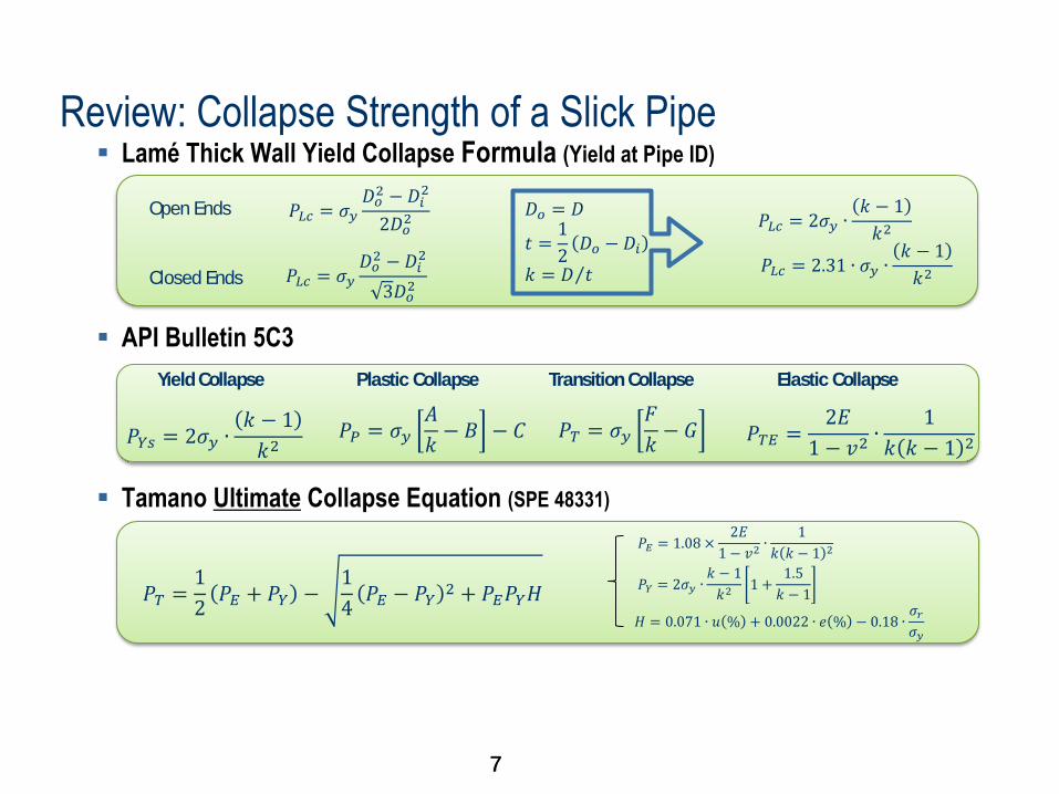
Review: Collapse Strength of a Slick Pipe Lamé Thick Wall Yield Collapse Formula (Yield at Pipe ID)
API Bulletin 5C3
Tamano Ultimate Collapse Equation (SPE 48331)
𝑃𝐿𝑐 = 𝜎𝑦𝐷𝑜2 −𝐷𝑖
2
2𝐷𝑜2 Open Ends
Closed Ends 𝑃𝐿𝑐 = 𝜎𝑦𝐷𝑜2 − 𝐷𝑖
2
3𝐷𝑜2
𝐷𝑜 = 𝐷
𝑡 =1
2𝐷𝑜 − 𝐷𝑖
𝑘 = 𝐷 𝑡
𝑃𝐿𝑐 = 2𝜎𝑦 ∙𝑘 − 1
𝑘2
𝑃𝐿𝑐 = 2.31 ∙ 𝜎𝑦 ∙𝑘 − 1
𝑘2
𝑃𝑌𝑠 = 2𝜎𝑦 ∙𝑘 − 1
𝑘2
Yield Collapse
𝑃𝑃 = 𝜎𝑦𝐴
𝑘− 𝐵 − 𝐶
Plastic Collapse
𝑃𝑇 = 𝜎𝑦𝐹
𝑘− 𝐺
Transition Collapse
𝑃𝑇𝐸 =2𝐸
1 − 𝑣2∙
1
𝑘 𝑘 − 1 2
Elastic Collapse
𝑃𝑇 =1
2𝑃𝐸 + 𝑃𝑌 −
1
4𝑃𝐸 − 𝑃𝑌
2 + 𝑃𝐸𝑃𝑌𝐻
𝑃𝐸 = 1.08 ×2𝐸
1 − 𝑣2∙
1
𝑘 𝑘 − 1 2
𝑃𝑌 = 2𝜎𝑦 ∙𝑘 − 1
𝑘21 +
1.5
𝑘 − 1
𝐻 = 0.071 ∙ 𝑢 % + 0.0022 ∙ 𝑒 % − 0.18 ∙𝜎𝑟𝜎𝑦
7
8 8
Ultimate Collapse Strength of Scalloped Gun Carriers
𝑃𝑐 = 𝜇 ∙ 𝑃𝑇
𝜇 – Collapse strength reduction factor due to scallops
𝑃𝑇 – Tamano ultimate collapse strength equation
𝝁
𝑃𝑇 𝑃𝑐
Definition
Slick Pipe Recessed Pipe Collapse strength
reduction factor
8
9 9
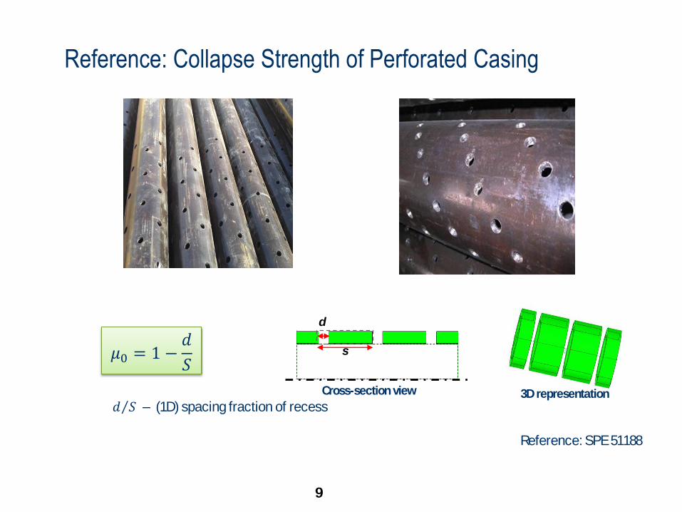
Reference: Collapse Strength of Perforated Casing
𝜇0 = 1 −𝑑
𝑆
Reference: SPE 51188
𝑑 𝑆 – (1D) spacing fraction of recess
3D representation
d
s
Cross-section view
9
10 10
𝜇 for Scalloped Gun Carriers
𝜇1 = 1 −𝑑
𝑆∙ℎ
𝑡
𝜇2 = 1 − 𝑓𝑟
𝜇3 = 1 − 𝛼𝑓𝑟
𝑓𝑟 – (3D) volume fraction of recess
𝛼 – fitting factor
h
t
d
Cross-section view 3D representation
s 𝑑×ℎ
𝑆×𝑡 – (2D) area fraction of recess
10
11 11
III. FEA and Test Validation
11
12 12
Modeling Approach Description Nonlinear post-buckling analysis using Riks method based on
arc length scheme in ABAQUS
Material model: isotropic hardening plasticity with bilinear,
power law or measured stress-strain curve
Boundary conditions: external pressure prescribed on the
exterior surface with end connection supported
Collapse Criteria When the collapse pressure is reached, the structure will deform dramatically and lose pressure-bearing
capacity.
Local Yielding
12
13 13
Physical Understanding of Collapse (Post-buckling)
0 0.05 0.1 0.15 0.2 0.25 0.30
0.2
0.4
0.6
0.8
1
1.2
U/D
P/P
ma
x
Collapse
P3
P1
P2
-3 -2 -1 0 1 2 30
0.05
0.1
0.15
0.2
0.25
0.3
x/S
U/D
Collapse
P1
P2
P3
Collapse pressure definition
13
14 14
Example: Collapse Animation of 15SPF 5 FT
Deformation Scale Factor = 1
14
15 15
Test Validation of FEA
Description Test Temp
[Deg F]
D/t Tested Collapse
Pressure
[psi]
FEA
𝑷𝒄𝒐𝒍𝒍𝒂𝒑𝒔𝒆
[psi]
Difference
with Tests [%]
Test 1 368 9.4 32,250 30,660 -4.9%
Test 2 318 10.7 22,500 22,831 +1.5%
Test 3 250 10.7 24,263 23,651 -2.5%
Test 4 250 14.0 18,329 18,633 +1.7%
Test 5 400 11.6 22,745 23,311 +2.4%
Note:
• Detailed geometric, product name and material parameters are confidential.
• Stress/strain data utilized in the FEA analyses is full measured data from a test
15
16 16
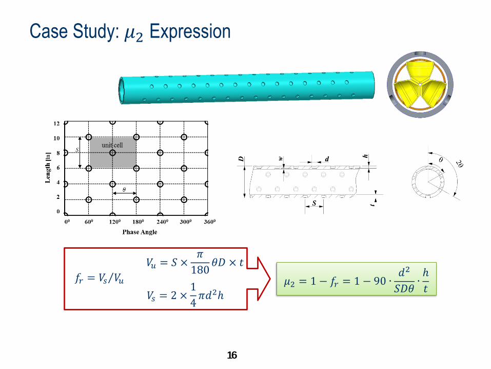
Case Study: 𝜇2 Expression
𝜇2 = 1 − 𝑓𝑟 = 1 − 90 ∙𝑑2
𝑆𝐷𝜃∙ℎ
𝑡 𝑓𝑟 = 𝑉𝑠 𝑉𝑢
𝑉𝑢 = 𝑆 ×𝜋
180𝜃𝐷 × 𝑡
𝑉𝑠 = 2 ×1
4𝜋𝑑2ℎ
16
17
Case Study: Parametric Study of 7-in OD, 5-ft Length Carrier
17
D [in] t [in] q [deg] S [in] w [in] d [in]
7
0.5
0.7
1.0
60 4.0 0.2 1.0
D [in] t [in] q [deg] S [in] h [in] d [in]
7 0.7
25.7
36
45
60
90
4.0 0.5 1.0
D [in] t [in] q [deg] S [in] h [in] d [in]
7 0.7 60
4.0
6.0
8.0
12.0
16.0
0.5 1.0
D [in] t [in] q [deg] S [in] h [in] d [in]
7 0.7 60 4.0
0.3
0.4
0.5
0.6
1.0
D [in] t [in] q [deg] S [in] h [in] d [in]
7 0.7 60 4.0 0.5
0.7
1.0
1.3
D [in] t [in]
7
0.5
0.7
1.0
Dimension of slick pipes
Wall Thickness, t
Angular Phasing, q
Longitudinal Spacing, S
Scallop Depth, h
Scallop Diameter, d
𝜇FEA = 𝑃scallopFEA 𝑃pipe
FEA
Definition of “true” 𝝁
18 18
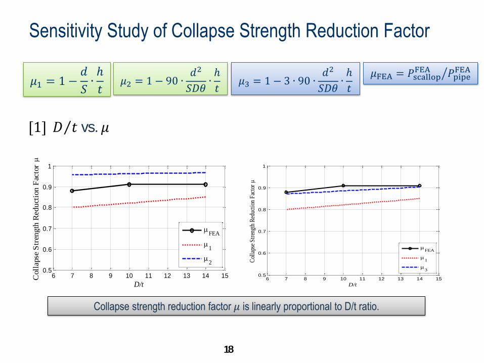
Sensitivity Study of Collapse Strength Reduction Factor
𝜇1 = 1 −𝑑
𝑆∙ℎ
𝑡 𝜇2 = 1 − 90 ∙
𝑑2
𝑆𝐷𝜃∙ℎ
𝑡
[1] 𝐷 𝑡 vs. 𝜇
𝜇3 = 1 − 3 ∙ 90 ∙𝑑2
𝑆𝐷𝜃∙ℎ
𝑡
𝜇FEA = 𝑃scallopFEA 𝑃pipe
FEA
6 7 8 9 10 11 12 13 14 150.5
0.6
0.7
0.8
0.9
1
D/t
Coll
apse
Str
ength
Reduct
ion F
acto
r
FEA
1
2
6 7 8 9 10 11 12 13 14 150.5
0.6
0.7
0.8
0.9
1
D/t
Col
laps
e S
tren
gth
Red
ucti
on F
acto
r
FEA
1
3
Collapse strength reduction factor 𝜇 is linearly proportional to D/t ratio.
18
19 19
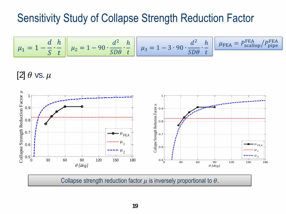
Sensitivity Study of Collapse Strength Reduction Factor
𝜇1 = 1 −𝑑
𝑆∙ℎ
𝑡 𝜇2 = 1 − 90 ∙
𝑑2
𝑆𝐷𝜃∙ℎ
𝑡
[2] 𝜃 vs. 𝜇
𝜇3 = 1 − 3 ∙ 90 ∙𝑑2
𝑆𝐷𝜃∙ℎ
𝑡
𝜇FEA = 𝑃scallopFEA 𝑃pipe
FEA
0 30 60 90 120 150 1800.5
0.6
0.7
0.8
0.9
1
q [deg]
Coll
apse
Str
ength
Reduct
ion F
acto
r
FEA
1
2
0 30 60 90 120 150 1800.5
0.6
0.7
0.8
0.9
1
q [deg]
Col
laps
e S
tren
gth
Red
ucti
on F
acto
r
FEA
1
3
Collapse strength reduction factor 𝜇 is inversely proportional to 𝜃.
19
20 20
Sensitivity Study of Collapse Strength Reduction Factor
𝜇1 = 1 −𝑑
𝑆∙ℎ
𝑡 𝜇2 = 1 − 90 ∙
𝑑2
𝑆𝐷𝜃∙ℎ
𝑡
3 𝑆 vs. 𝜇
𝜇3 = 1 − 3 ∙ 90 ∙𝑑2
𝑆𝐷𝜃∙ℎ
𝑡
𝜇FEA = 𝑃scallopFEA 𝑃pipe
FEA
2 4 6 8 10 12 14 16 18 20 22 240.5
0.6
0.7
0.8
0.9
1
S [in]
Coll
apse
Str
ength
Reduct
ion F
acto
r
FEA
1
2
2 4 6 8 10 12 14 16 18 20 22 240.5
0.6
0.7
0.8
0.9
1
S [in]
Col
laps
e S
tren
gth
Red
ucti
on F
acto
r
FEA
1
3
Collapse strength reduction factor 𝜇 is inversely proportional to S.
20
21 21
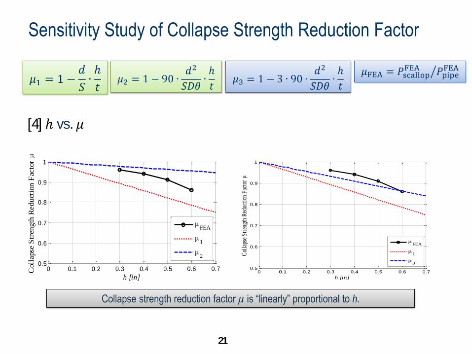
Sensitivity Study of Collapse Strength Reduction Factor
𝜇1 = 1 −𝑑
𝑆∙ℎ
𝑡 𝜇2 = 1 − 90 ∙
𝑑2
𝑆𝐷𝜃∙ℎ
𝑡
[4] ℎ vs. 𝜇
𝜇3 = 1 − 3 ∙ 90 ∙𝑑2
𝑆𝐷𝜃∙ℎ
𝑡
𝜇FEA = 𝑃scallopFEA 𝑃pipe
FEA
0 0.1 0.2 0.3 0.4 0.5 0.6 0.70.5
0.6
0.7
0.8
0.9
1
h [in]
Coll
apse
Str
ength
Reduct
ion F
acto
r
FEA
1
2
0 0.1 0.2 0.3 0.4 0.5 0.6 0.70.5
0.6
0.7
0.8
0.9
1
h [in]
Col
laps
e S
tren
gth
Red
ucti
on F
acto
r
FEA
1
3
Collapse strength reduction factor 𝜇 is “linearly” proportional to h.
21
22 22
Sensitivity Study of Collapse Strength Reduction Factor
𝜇1 = 1 −𝑑
𝑆∙ℎ
𝑡 𝜇2 = 1 − 90 ∙
𝑑2
𝑆𝐷𝜃∙ℎ
𝑡
[5] 𝑑 vs. 𝜇
𝜇3 = 1 − 3 ∙ 90 ∙𝑑2
𝑆𝐷𝜃∙ℎ
𝑡
𝜇FEA = 𝑃scallopFEA 𝑃pipe
FEA
0 0.3 0.6 0.9 1.2 1.50.5
0.6
0.7
0.8
0.9
1
d [in]
Coll
apse
Str
ength
Reduct
ion F
acto
r
FEA
1
2
0 0.3 0.6 0.9 1.2 1.50.5
0.6
0.7
0.8
0.9
1
d [in]
Col
laps
e S
tren
gth
Red
ucti
on F
acto
r
FEA
1
3
Collapse strength reduction factor 𝜇 is a quadratic function of d.
22
23 23
IV. Conclusions and Future Work
23
24 24
Conclusions and Future Work An analytical collapse strength equation based on Tamano formula was proposed for scalloped
perforating guns.
The proposed equation was thoroughly validated with the aid of FEA in a multivariable parametric
space – an analysis hardly affordable with the use of physical tests.
An FEA method used to validate the proposed equation showed strong agreement with the test
data giving collapse predictions for scalloped tubulars within 5% of the test results.
The method applied to scalloped perforating guns can also be used for any tubulars with
patterned cutouts or recesses, such as prepacked sand screens, perforated or slotted liners, etc.
24
25 25
Questions?
25
Publications
• Zhao, H., Iblings, D., Barykin, A., and Mehdi, M., 2015, Plastic Collapse Behaviors of Tubulars with Recess Patterns,
Proceedings of ASME International Mechanical Engineering Congress & Exposition, IMECE2015-50204, Houston, TX.
• Zhao, H., Iblings, D., Barykin, A., and Mehdi, M., 2016, Plastic Collapse Behaviors of Tubulars with Recess Patterns, ASCE-
ASME Journal of Risk and Uncertainty in Engineering Systems, Part B: Mechanical Engineering , Accepted.