INSTALLATION GENERAL Read these instructions through carefully before unpacking, inspecting, and installing Sunnen KKN-100 Square Honing Fixture. SUGGESTED TOOLS & MATERIALS The following tools and materials are required for unpacking and installing the Fixture. KKN-270 Square Honing Setup Kit Knife Tin Snips Hex Wrenches Coarse File Open End Wrenches Hacksaw Cleaning Solvent INSTALLATION All references to right and left in these instructions are, unless otherwise noted, as seen by the operator as one looks at the Fixture or Machine. 1. Remove Fixture from its shipping carton. 2. Check contents against packing list (see Figure A, page 4a & Figure B, page 4d). 3. Remove right rear Splash Guard from Machine Top Plate. 4. On older Machine use the Template, located in center of these instructions, to lay out, drill and tap mounting holes (see center pullout). 5. Place Spacers on Top Plate as shown and align holes in Spacers with mounting holes in Top Plate (see Figure 1). 6. Remove Guide Cover. Save for reinstallation. 7. Reinstall Belt Guard. 8. Position Fixture on Spacers with Fixture Arm forward as shown (see Figure 2). Align holes in Bearing Tube Feet, Spacers and Top Plate and secure with Mounting Bolts and Lockwashers provided. Snug, do not tighten at this time. HORIZONTAL ALIGNMENT To check the horizontal alignment of the Fixture Arm, proceed as follows: 1. Obtain a Dial Indicator. 2. Install Torque or Oiler Bar, whichever Bar fits your Dial Indicator, in Fixture. 3. Clamp Indicator to Bar, so tip rests on the side of the Spindle Nose as shown (see Figure 3). Zero Indicator. 4. Move Fixture Arm back and forth (stroke) and note runout on Indicator. This is to check parallelism between side of Spindle Nose and the I-KKN-100I INSTALLATION, OPERATION & MAINTENANCE INSTRUCTIONS for SUNNEN KKN-100 SQUARE HONING FIXTURE http://www.sunnen.com SUNNEN PRODUCTS COMPANY • 7910 MANCHESTER AVENUE • ST. LOUIS, MO 63143, U.S.A. • PHONE: 314-781-2100 FIGURE 2, Position Fixture FIGURE 1, Top Plate GUIDE COVER SPACER UNUSED TAPPED HOLE BEARING TUBE FEET (4) TORQUE BAR FIXTURE ARM FIGURE 3, Indicator TORQUE BRACKET ASSEMBLY CLAMP GROOVE OILER BAR DIAL INDICATOR SPINDLE NOSE
Transcript
INSTALLATIONGENERALRead these instructions through carefully beforeunpacking, inspecting, and installing Sunnen KKN-100 Square Honing Fixture.
SUGGESTED TOOLS & MATERIALSThe following tools and materials are required forunpacking and installing the Fixture.
KKN-270 Square Honing Setup KitKnife Tin SnipsHex Wrenches Coarse FileOpen End Wrenches HacksawCleaning Solvent
INSTALLATIONAll references to right and left in these instructionsare, unless otherwise noted, as seen by the operatoras one looks at the Fixture or Machine.
1. Remove Fixture from its shipping carton.
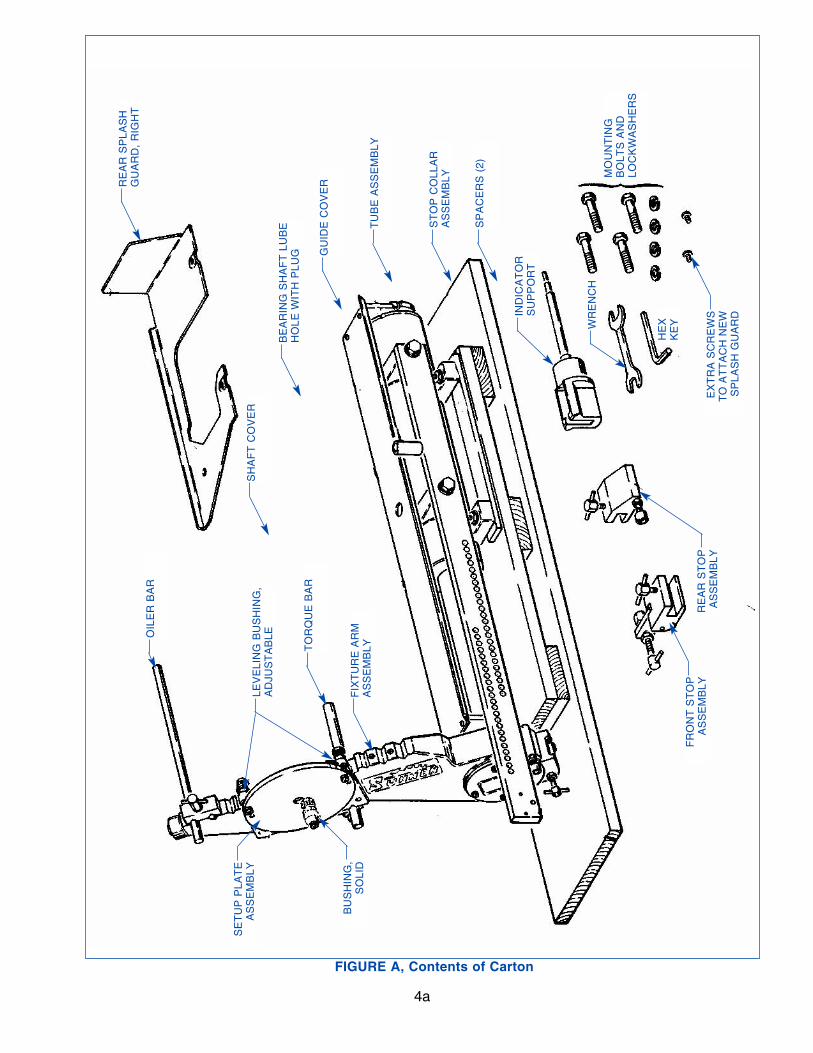
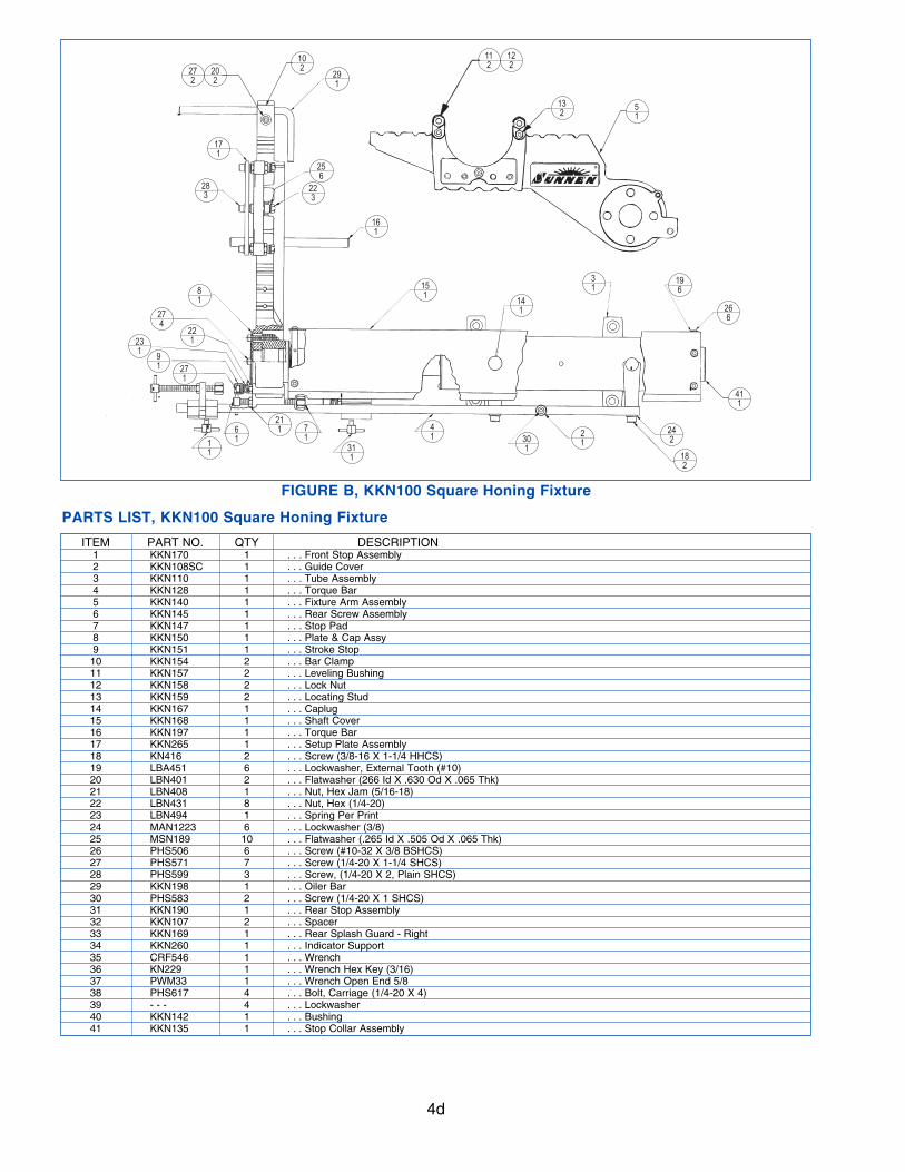
2. Check contents against packing list (see Figure A, page 4a & Figure B, page 4d).3. Remove right rear Splash Guard from Machine
Top Plate.
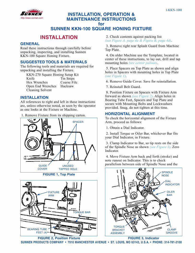
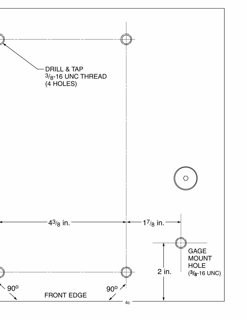
4. On older Machine use the Template, located incenter of these instructions, to lay out, drill and tapmounting holes (see center pullout).5. Place Spacers on Top Plate as shown and align
holes in Spacers with mounting holes in Top Plate(see Figure 1).6. Remove Guide Cover. Save for reinstallation.
7. Reinstall Belt Guard.
8. Position Fixture on Spacers with Fixture Armforward as shown (see Figure 2). Align holes inBearing Tube Feet, Spacers and Top Plate andsecure with Mounting Bolts and Lockwashers provided. Snug, do not tighten at this time.
HORIZONTAL ALIGNMENTTo check the horizontal alignment of the FixtureArm, proceed as follows:
1. Obtain a Dial Indicator.
2. Install Torque or Oiler Bar, whichever Bar fitsyour Dial Indicator, in Fixture.
3. Clamp Indicator to Bar, so tip rests on the sideof the Spindle Nose as shown (see Figure 3). ZeroIndicator.
4. Move Fixture Arm back and forth (stroke) andnote runout on Indicator. This is to checkparallelism between side of Spindle Nose and the
SUNNEN PRODUCTS COMPANY • 7910 MANCHESTER AVENUE • ST. LOUIS, MO 63143, U.S.A. • PHONE: 314-781-2100FIGURE 2, Position Fixture
FIGURE 1, Top Plate
GUIDECOVER
SPACER
UNUSEDTAPPED HOLE
BEARING TUBEFEET (4)
TORQUE BAR
FIXTUREARM
FIGURE 3, Indicator
TORQUEBRACKET
ASSEMBLYCLAMP
GROOVE
OILERBAR
DIAL INDICATOR
SPINDLENOSE
line of motion of the Fixture Arm.
5. Runout should be within .002 in. (0,05mm) overthe 2.3in. (58mm) straight length of the Spindle Nose.
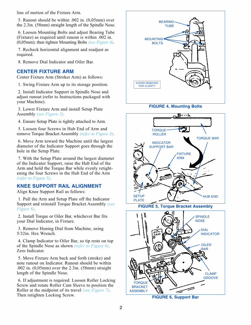
6. Loosen Mounting Bolts and adjust Bearing Tube(Fixture) as required until runout is within .002 in.(0,05mm); then tighten Mounting Bolts (see Figure 4).7. Recheck horizontal alignment and readjust as
required.
8. Remove Dial Indicator and Oiler Bar.
CENTER FIXTURE ARMCenter Fixture Arm (Stroker Arm) as follows:
1. Swing Fixture Arm up to its storage position.
2. Install Indicator Support in Spindle Nose andadjust runout (refer to Instructions packaged withyour Machine).
3. Lower Fixture Arm and install Setup PlateAssembly (see Figure 5).4. Ensure Setup Plate is tightly attached to Arm.
5. Loosen four Screws in Hub End of Arm andremove Torque Bracket Assembly (refer to Figure 3).6. Move Arm toward the Machine until the largest
diameter of the Indicator Support goes through thehole in the Setup Plate.
7. With the Setup Plate around the largest diameterof the Indicator Support, raise the Hub End of theArm and hold the Torque Bar while evenly retight-ening the four Screws in the Hub End of the Arm(refer to Figure 5).
KNEE SUPPORT RAIL ALIGNMENTAlign Knee Support Rail as follows:
1. Pull the Arm and Setup Plate off the IndicatorSupport and reinstall Torque Bracket Assembly (seeFigure 6).2. Install Torque or Oiler Bar, whichever Bar fits
your Dial Indicator, in Fixture.
3. Remove Honing Dial from Machine, using5/32in. Hex Wrench.
4. Clamp Indicator to Oiler Bar, so tip rests on topof the Spindle Nose as shown (refer to Figure 6).Zero Indicator.
5. Move Fixture Arm back and forth (stroke) andnote runout on Indicator. Runout should be within.002 in. (0,05mm) over the 2.3in. (58mm) straightlength of the Spindle Nose.
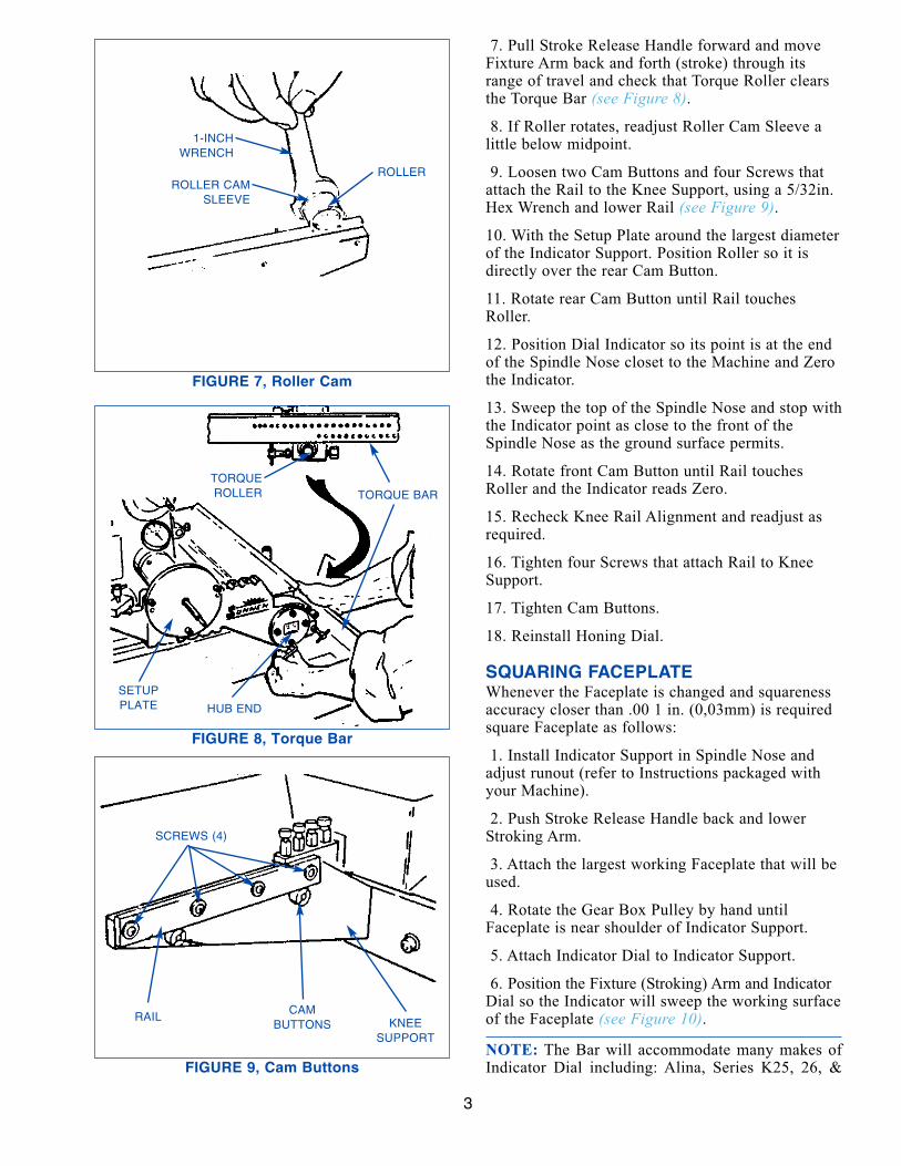
6. If adjustment is required: Loosen Roller LockingScrew and rotate Roller Cam Sleeve to position theRoller at the midpoint of its travel (see Figure 7).Then retighten Locking Screw.
2
FIGURE 6, Support Bar
FIGURE 4, Mounting Bolts
FIGURE 5, Torque Bracket Assembly
COVER REMOVEDFOR CLARITY
MOUNTINGBOLTS
BEARINGTUBE
FIXTUREARM
HUB ENDSETUPPLATE
INDICATORSUPPORT BAR
TORQUE BAR
TORQUEROLLER
CLAMPGROOVE
OILERBAR
DIAL INDICATOR
SPINDLENOSE
TORQUEBRACKET
ASSEMBLY
7. Pull Stroke Release Handle forward and moveFixture Arm back and forth (stroke) through itsrange of travel and check that Torque Roller clearsthe Torque Bar (see Figure 8).
9. Loosen two Cam Buttons and four Screws thatattach the Rail to the Knee Support, using a 5/32in.Hex Wrench and lower Rail (see Figure 9).
10. With the Setup Plate around the largest diameterof the Indicator Support. Position Roller so it isdirectly over the rear Cam Button.
11. Rotate rear Cam Button until Rail touchesRoller.
12. Position Dial Indicator so its point is at the endof the Spindle Nose closet to the Machine and Zerothe Indicator.
13. Sweep the top of the Spindle Nose and stop withthe Indicator point as close to the front of theSpindle Nose as the ground surface permits.
14. Rotate front Cam Button until Rail touchesRoller and the Indicator reads Zero.
15. Recheck Knee Rail Alignment and readjust asrequired.
16. Tighten four Screws that attach Rail to KneeSupport.
17. Tighten Cam Buttons.
18. Reinstall Honing Dial.
SQUARING FACEPLATEWhenever the Faceplate is changed and squarenessaccuracy closer than .00 1 in. (0,03mm) is requiredsquare Faceplate as follows:
1. Install Indicator Support in Spindle Nose andadjust runout (refer to Instructions packaged withyour Machine).
2. Push Stroke Release Handle back and lowerStroking Arm.
3. Attach the largest working Faceplate that will beused.
4. Rotate the Gear Box Pulley by hand untilFaceplate is near shoulder of Indicator Support.
5. Attach Indicator Dial to Indicator Support.
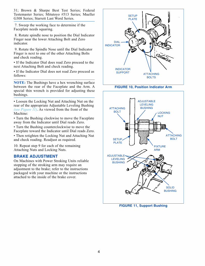
6. Position the Fixture (Stroking) Arm and IndicatorDial so the Indicator will sweep the working surfaceof the Faceplate (see Figure 10).
NOTE: The Bar will accommodate many makes ofIndicator Dial including: Alina, Series K25, 26, &
3
FIGURE 9, Cam Buttons
FIGURE 7, Roller Cam
FIGURE 8, Torque Bar
ROLLERROLLER CAM
SLEEVE
1-INCHWRENCH
HUB END
SETUPPLATE
TORQUEROLLER
KNEESUPPORT
SCREWS (4)
CAMBUTTONS
RAIL
TORQUE BAR
31; Brown & Sharpe Best Test Series; FederalTestemaster Series; Mitutoyo #513 Series; MuellerG308 Series; Starrett Last Word Series.
7. Sweep the working face to determine if theFaceplate needs squaring.
8. Rotate spindle nose to position the Dial IndicatorFinger near the lower Attaching Bolt and Zeroindicator.
9. Rotate the Spindle Nose until the Dial IndicatorFinger is next to one of the other Attaching Boltsand check reading.
• If the Indicator Dial does read Zero proceed to thenext Attaching Bolt and check reading.
• If the Indicator Dial does not read Zero proceed asfollows:
NOTE: The Bushings have a hex wrenching surfacebetween the rear of the Faceplate and the Arm. Aspecial thin wrench is provided for adjusting thesebushings.
• Loosen the Locking Nut and Attaching Nut on therear of the appropriate Adjustable Leveling Bushing(see Figure 11). As viewed from the front of theMachine:
• Turn the Bushing clockwise to move the Faceplateaway from the Indicator until Dial reads Zero.
• Turn the Bushing counterclockwise to move theFaceplate toward the Indicator until Dial reads Zero.
• Then retighten the Locking Nut and Attaching Nutand check reading. Readjust as required.
10. Repeat step 9 for each of the remainingAttaching Nuts and Locking Nuts.
BRAKE ADJUSTMENTOn Machines with Power Stroking Units reliablestopping of the stroking arm may require an adjustment to the brake; refer to the instructionspackaged with your machine or the instructionsattached to the inside of the brake cover.
4
FIGURE 10, Position Indicator Arm
FIGURE 11, Support Bushing
ATTACHINGBOLTS
INDICATORSUPPORT
SETUPPLATE
DIALINDICATOR
SOLIDBUSHING
ADJUSTABLELEVELINGBUSHING
SETUPPLATE
ATTACHINGBOLT
FIXTUREARM
ATTACHINGBOLT
LOCKINGNUT
ADJUSTABLELEVELINGBUSHING
4a
FIGURE A, Contents of Carton
RE
AR
SP
LAS
HG
UA
RD
, R
IGH
T
BE
AR
ING
SH
AF
T L
UB
EH
OLE
WIT
H P
LUG
SH
AF
T C
OV
ER
GU
IDE
CO
VE
R
TU
BE
AS
SE
MB
LY
ST
OP
CO
LLA
RA
SS
EM
BLY
SP
AC
ER
S (
2)
IND
ICA
TO
RS
UP
PO
RT
MO
UN
TIN
GB
OLT
S A
ND
LOC
KW
AS
HE
RS
WR
EN
CH
HE
XK
EY
EX
TR
A S
CR
EW
ST
O A
TT
AC
H N
EW
SP
LAS
H G
UA
RD
RE
AR
ST
OP
AS
SE
MB
LY
FR
ON
T S
TO
PA
SS
EM
BLY
FIX
TU
RE
AR
MA
SS
EM
BLYT
OR
QU
E B
AR
LEV
ELI
NG
BU
SH
ING
,A
DJU
ST
AB
LE
BU
SH
ING
,S
OLI
D
SE
TU
P P
LAT
EA
SS
EM
BLY
OIL
ER
BA
R
NOTICEREMOVE THIS DRAWING FOR DRILLINGMOUNTING HOLES IN MBB-1650 HONINGMACHINES, SERIAL No’s 51017 ANDLOWER.
DO NOT USE THIS DRAWING AS A TEM-PLATE, AS PAPER SHINKAGE MIGHTCAUSE ERRORS IN THE DIMENSIONS.
LAYOUT PATTERN WITH A SCRIBE AND ACOMBINATION SQUARE.
(IF YOU DO NOT NEED THIS SHEET,REMOVE AND DISCARD.)
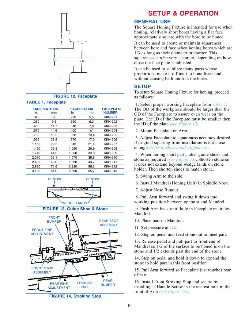
SETUP & OPERATIONGENERAL USEThe Square Honing Fixture is intended for use whenhoning, relatively short bores having a flat faceapproximately square with the bore to be honed.
It can be used to create or maintain squarenessbetween bore and face when honing bores which are1/3 as long as their diameter or shorter. Thissquareness can be very accurate, depending on howclose the face plate is adjusted.
It can be used to stabilize many parts whose proportions make it difficult to hone free-hand without causing bellmouth in the bores.
SETUPTo setup Square Honing Fixture for honing, proceedas follows:
1. Select proper working Faceplate from Table 1.The OD of the workpiece should be larger than theOD of the Faceplate to assure even wear on theplate. The ID of the Faceplate must be smaller thenthe ID of the plate (see Figure 12).2. Mount Faceplate on Arm.
3. Adjust Faceplate to squareness accuracy desiredif original squaring from installation is not closeenough (refer to Horizontal Alignment).4. When honing short parts, alter guide shoes and
stone as required (see Figure 13). Shorten stone soit does not extend beyond wedge lands on stoneholder. Then shorten shoes to match stone.
5. Swing Arm to the side.
6. Install Mandrel (Honing Unit) in Spindle Nose.
7. Adjust Nose Runout.
8. Pull Arm forward and swing it down intoworking position between operator and Mandrel.
9. Push Arm back until hole in Faceplate encirclesMandrel.
10. Place part on Mandrel.
11. Set pressure at 1/2.
12. Step on pedal and feed stone out to meet part.
13. Release pedal and pull part to front end ofMandrel so 1/2 of the surface to be honed is on thestone and 1/2 extends past the end of the stone.
14. Step on pedal and hold it down to expand thestone to hold part in this front position.
15. Pull Arm forward so Faceplate just touches rearof part.
16. Install Front Stroking Stop and secure byinstalling T-Handle Screw in the nearest hole in thefront of Arm (see Figure 14).
9
FIGURE 14, Stroking Stop
FIGURE 12, Faceplate
FIGURE 13, Guide Shoe & Stone
TABLE 1, Faceplate
FACEPLATE OD FACEPLATEID FACEPLATEin. mm In. mm NUMBER
17. Make fine adjustment using Front Stop FineAdjustment and then tighten Locking Screw.
18. Push Arm back and then release pedal.
19. Move part to rear end of Mandrel so 1/2 of thesurface to be honed is on the stone and 1/2 extendspast the end of the stone.
20. Step on pedal and hold it down to expand thestone to hold part in this rear position.
21. Pull Arm forward so Faceplate just touches rearof part.
22. Install Rear Stop Assembly and secure byinstalling T-Handle Screw in the nearest hole in thefront of Arm (refer to Figure 14).23. Make fine adjustment using Rear Stop FineAdjustment and then tighten Locking Screw.
NOTE: Bumper Springs provide a maximum cushion of 1/16 in. (0,002mm) at either end of thestroke. Make allowance for this when honing veryshort bores. Bumper Springs cushion can be madefirmer or softer be releasing Locking Nut and turningthe Screw in the center of the Bumper. RetightenLocking Nut when desired cushion is obtained.
HONING THE PARTHone the part using Sunnen's KKN-100 SquareHoning Fixture as follows:
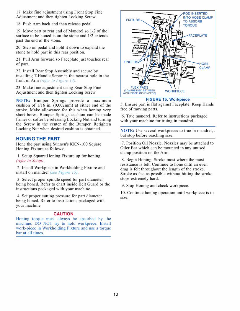
1. Setup Square Honing Fixture up for honing(refer to Setup).2. Install Workpiece in Workholding Fixture and
install on mandrel (see Figure 15).3. Select proper spindle speed for part diameter
being honed. Refer to chart inside Belt Guard or theinstructions packaged with your machine.
4. Set proper cutting pressure for part diameterbeing honed. Refer to instructions packaged withyour machine.
CAUTIONHoning torque must always be absorbed by themachine. DO NOT try to hold workpiece. Installwork-piece in Workholding Fixture and use a torquebar at all times.
5. Ensure part is flat against Faceplate. Keep Handsfree of moving parts.
6. True mandrel. Refer to instructions packagedwith your machine for truing in mandrel.
NOTE: Use several workpieces to true in mandrel, .but stop before reaching size.
7. Position Oil Nozzle. Nozzles may be attached toOiler Bar which can be mounted in any unusedclamp position on the Arm.
8. Begin Honing. Stroke most where the mostresistance is felt. Continue to hone until an evendrag is felt throughout the length of the stroke.Stroke as fast as possible without hitting the strokestops extremely hard.
9. Stop Honing and check workpiece.
10. Continue honing operation until workpiece is tosize.
10
FIGURE 15, Workpiece
FLEX PADS(COMPRESSED BETWEEN
WORKPIECE AND FINGERS)WORKPIECE
HOSECLAMP
FACEPLATE
ROD INSERTEDINTO HOSE CLAMPTO ABSORBTORQUE
FIXTURE
FINGERS
MAINTENANCEGENERALThe following routine maintenance is provided as aguide in caring for your Square Honing Fixture.
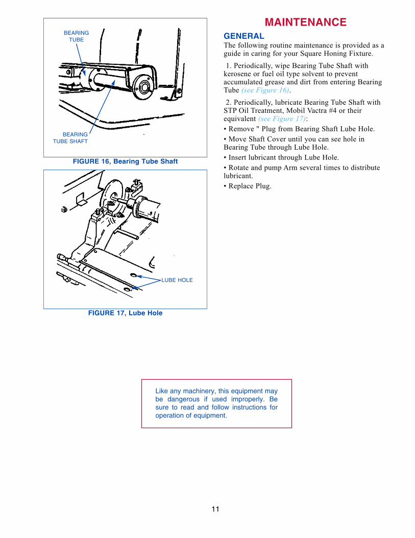
1. Periodically, wipe Bearing Tube Shaft withkerosene or fuel oil type solvent to preventaccumulated grease and dirt from entering BearingTube (see Figure 16).2. Periodically, lubricate Bearing Tube Shaft with
STP Oil Treatment, Mobil Vactra #4 or theirequivalent (see Figure 17):• Remove " Plug from Bearing Shaft Lube Hole.
• Move Shaft Cover until you can see hole inBearing Tube through Lube Hole.
• Insert lubricant through Lube Hole.
• Rotate and pump Arm several times to distributelubricant.
• Replace Plug.
11
FIGURE 16, Bearing Tube Shaft
FIGURE 17, Lube Hole
Like any machinery, this equipment maybe dangerous if used improperly. Besure to read and follow instructions foroperation of equipment.
SUNNEN PRODUCTS COMPANY7910 Manchester Road, St. Louis, MO 63143 U.S.A.Phone: 314-781-2100 Fax: 314-781-2268U.S.A. Toll-Free Sales and Service:1-800-325-3670International Division Fax: 314-781-6128
Sunnen® reserves the right to change orrevise specifications and product designin connection with any feature of ourproducts contained herein. Such changesdo not entitle the buyer to correspondingchanges, improvements, additions, orreplacements for equipment, supplies oraccessories previously sold. Informationcontained herein is considered to beaccurate based on available informationat the time of printing. Should any discrepancy of information arise, Sunnenrecommends that user verify discrepancywith Sunnen before proceeding.
“SUNNEN® AND THE SUNNEN LOGO ARE REGISTERED TRADEMARKS OF SUNNEN PRODUCTS COMPANY.”