I NASA Technical Memorandum 100793 I . I I I Mechanics of Composite Materials: Past, Present, and Future christos c. chamis Lewis Research Center Cleveland, Ohio - (EaSA-TB- lOOn3) lECBABiICS CF CGCOPGSXTP ma- 13744 41 P CSCL 11D EILTEBZALS: PAST, FEESENT ALLC EGTUBE (NASS) Uaclas ~3124 o 3 2 ~ 3 Presented at the I 21st Annual Meeting of the Society for Engineering Science Blacksburg, Virginia, October 15-17, 1984
Transcript
I NASA Technical Memorandum 100793
I . I I
I Mechanics of Composite Materials: Past, Present, and Future
christos c. chamis Lewis Research Center Cleveland, Ohio
-
(EaSA-TB- l O O n 3 ) lECBABiICS CF CGCOPGSXTP m a - 13744 41 P CSCL 11D EILTEBZALS: PAST, FEESENT ALLC EGTUBE (NASS)
Uaclas ~ 3 1 2 4 o 3 2 ~ 3
Presented at the I
21st Annual Meeting of the Society for Engineering Science Blacksburg, Virginia, October 15-17, 1984
MECHANICS OF COMPOSITE MATERIALS: PAST, PRESENT, AND FUTURE
C h r i s t o s C. Chamis N a t i o n a l Ae ronau t i cs and Space A d m i n i s t r a t i o n
Lewis Research Center C leve land, Oh io 44135
ABS TRACT
Composite mechanics d i s c i p l i n e s a r e presented and desc r ibed a t t h e i r
v a r i o u s l e v e l s o f s o p h i s t i c a t i o n and a t t e n d a n t sca les o f a p p l i c a t i o n .
C o r r e l a t i o n w i t h exper imenta l da ta i s used as t h e pr ime d i s c r i m i n a t o r between
a l t e r n a t i v e methods and l e v e l of s o p h i s t i c a t i o n . Ma jor emphasis i s p laced
on: ( 1 ) where composi te mechanics has been; ( 2 ) what i t has accompl ished; ( 3 )
where i t i s headed, based on p resen t research a c t i v i t i e s ; and ( 4 ) a t t h e r i s k
o f be ing presumptuous, where i t shou ld be headed. The d i s c u s s i o n i s developed
u s i n g se lec ted , b u t t y p i c a l , examples o f each composi te mechanics d i s c i p l i n e
i d e n t i f y i n g degree o f success, w i t h r e s p e c t t o c o r r e l a t i o n w i t h exper imenta l
da ta , and problems remain ing . The d i s c u s s i o n i s cen te red about f i b e r / r e s i n
composi tes drawn m a i n l y from t h e a u t h o r ' s research a c t i v i t i e s l e x p e r i e n c e
spanning two decades a t Lewis.
STAR CATEGORY 24
Key words: Fiber-compos t e s ; R e s n -mat r ices ; I n t e r p l y h y b r i d s ; I n t r a p l y
h y b r i d s ; Micromechanics; Macromechanics; Combined-stress f a i l u r e ; Laminate
theo ry ; S i n g u l a r i t y mechanics; L i f e l d u r a b i l i t y ; F r a c t u r e toughness; Damage
t o l e r a n c e ; P rog ress i ve f r a c t u r e ; S t r u c t u r a l a n a l y s i s ; Envi ronmenta l e f f e c t s
INTRODUCTION/BACKGROUND
Composite mechanics has evolved to encompass a wide range of continuum
and discrete mechanics methods.
fiber/matrix composite behavior.
predicted at various inherent scales (corresponding to the fabrication
processes) in the composite from microstructure to structural response. Within
each inherent scale has evolved a specialty composites mechanics discipline
with several levels of sophistication.
These methods are used to study and predict
The composite behavior is studied and/or
The various levels of sophistication that have evolved in each composite
mechanics discipline were influenced by three important factors: (1)
capturing the intrinsic physics; ( 2 ) degree o f local detail desired; and (3)
technical interests of the investigator(s1. Collectively, these three factors
have led to numerous significant contributions at the various scales of
composite behavior.
The objective of this report is to describe/discuss composite mechanics
at its various levels of sophistication and attendant inherent scales of
application with respect to past, present, and future.
such a report is to stimulate thinking which will hopefully lead t o
lifejdurability; and ( 7 ) structural analysis. The scale levels associated
with each discipline and the various levels of sophistication of composite
math models in each discipline are described. What has been accomplished in
each discipline, emphasis on current research, and future trends are
summarized. The future trends are mainly conventional. Greater progress will
be achieved by pursuing unconventional and innovative methods which are
14
dedicated, adaptive, and expert-system-driven. Composite mechanics spans many
disciplines with each playing a very significant role in its future growth and
success. Successful contributions, which are timely and cost-effective, will
require the col lective/coord
di sc i pl i nes .
C11 Murthy, P.L.N. and Cham
nated research efforts of experts from these
REFERENCES
s , C.C., "ICAN: Integrated Composites Analyzer,"
NASA Report TM-83700, National Aeronautics and Space Administration,
Washington, DC, 1984.
C21 Chamis, C.C., "Simplified Composite Micromechanics Equations for Hygral,
Thermal and Mechanical Properties," SAMPE Quarterly, Vol. 15, Apr. 1984,
pp. 14-23. (NASA Report TM-83320, National Aeronautics and Space
Administration, Washington, DC, 1983.)
C31 Chamis, C.C., "Simplified Composite Micromechanics Equations for Strength,
Fracture Toughness, and Environmental Effects," NASA Report TM-83696,
National Aeronautics and Space Administration, Washington, DC, 1984.
[41 Chamis, C.C., Lark, R.F., and Sinclair, J.H., "Mechanical Property
Characterization o f Intraply Hybrid Composites," NASA Report TM-79306,
National Aeronautics and Space Administration, Washington, DC,. 1979.
C51 Chamis, C.C. and Sinclair, J.H., "DurabilitylLife of Fiber Composites in
Hygrothermomechanical Environments," in Composite Materials: Testinq and
Design, ASTM, Philadelphia, PA, 1982, pp. 498-512. (NASA Report TM-82749,
National Aeronautics and Space Administration, Washington, DC, 1981.)
[ 6 1 Chamis, C.C. and Smith, G.T., "Resin Selection Criteria for Tough
Composite Structures," AIAA Journal, Vol. 23, June 1985, pp. 902-911.
(NASA Report TM-83449, National Aeronautics and Space Administration,
Washington, DC, 1983.)
15 *
[ 7 1 Chamis, C.C. and S i n c l a i r , J.H., "Mechanical Behav io r and F r a c t u r e
C h a r a c t e r i s t i c s of O f f - A x i s F i b e r Composites: 11-Theory and Comparisons,"
NASA Repor t TP-1082, N a t i o n a l Ae ronau t i cs and Space A d m i n i s t r a t i o n ,
Washington, DC, 1978.
[ 8 1 Chamis, C.C., L a r k R.F., and S i n c l a i r , J.H., "An I n t e g r a t e d Theory for
P r e d i c t i n g t h e Hygrothermomechanical Response o f Advanced Composite
S t r u c t u r a l Components," NASA Repor t TM-73812, N a t i o n a l Ae ronau t i cs and
Space A d m i n i s t r a t i o n , Washington, DC, 1977.
[ 9 1 Chamis, C.C. and S u l l i v a n , T . M . , "Combined-Load S t r e s s - S t r a i n
R e l a t i o n s h i p s for Advanced F i b e r Composites," NASA Repor t TM-X-71825,
N a t i o n a l Ae ronau t i cs and Space A d m i n i s t r a t i o n , Washington, DC, 1976.
[ l o ] Mur thy , P.L.N. and Chamis, C.C., "A S tudy o f I n t e r p l y Layer E f f e c t s on
t h e Free Edge S t r e s s F i e l d of A n g l e p l i e d Laminates," Computers and
S t r u c t u r e s , Vol. 20, No. 1-3, 1985, pp. 431-441. (NASA Repor t TM-86924,
N a t i o n a l A e r o n a u t i c s and Space A d m i n i s t r a t i o n , Washington, DC, 1984.)
1111 Mur thy , P.L.N. and Chamis, C.C. , " I n t e r l a m i n a r F r a c t u r e Toughness:
Three-Dimensional F in i t e -E lemen t Mode l i ng f o r End-Notch and Mixed Mode
F lexu re , " NASA Repor t TM-87138, N a t i o n a l Ae ronau t i cs and Space
A d m i n i s t r a t i o n , Washington, DC, 1985.
[121 Chamis, C.C. and G i n t y , C . A . , "Composite D u r a b i l i t y and Damage
To lerance: S i m p l i f i e d P r e d i c t i v e Methods," NASA Repor t TM-100179,
N a t i o n a l Ae ronau t i cs and Space A d m i n i s t r a t i o n , Washington, DC, 1987.
[131 Chamis, C.C. and Smith, G . T . , "CODSTRAN: Composite D u r a b i l i t y S t r u c t u r a l
A n a l y s i s , " NASA Repor t TM-79070, N a t i o n a l Ae ronau t i cs and Space
I A d m i n i s t r a t i o n , Washington, DC, 1978. I
1 6
1141 I r v i n e , T.B. and Gin ty , C.A., "Progress ive F r a c t u r e o f F i b e r Composites,"
Journal o f Composite M a t e r i a l s , Vol. 20, Mar. 1986, pp. 166-184. (NASA
Report TM-83701, Nat iona l Aeronaut ics and Space A d m i n i s t r a t i o n ,
Washington, DC, 1983.)
C151 Chamis, C.C. and S i n c l a i r , J.H., "Ana lys is o f High V e l o c i t y Impact on
H y b r i d Composite Fan Blades," NASA Report TM-79133, i n S t r u c t u r e s ,
S t r u c t u r a l Dynamics, and M a t e r i a l s , A I A A , New York, 1979, pp. 249-257.
(Nat iona l Aeronaut ics and Space A d m i n i s t r a t i o n , Washington, DC, 1979.)
[161 Chamis, C.C. and Lynch, J.E., "High-Tip-Speed F i b e r Composite Fan Blades:
V i b r a t i o n and S t r e n g t h Ana lys is , : NASA Report TM-X-71589, N a t i o n a l
Aeronaut ics and Space A d m i n i s t r a t i o n , Washington, DC, 1974.
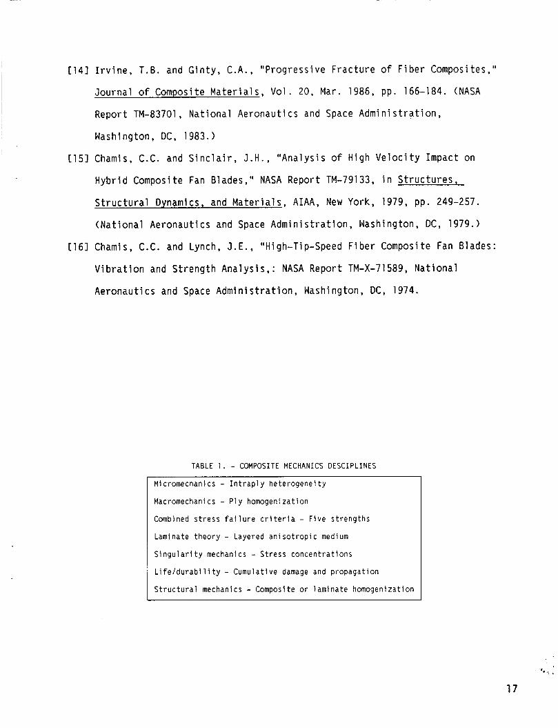
TABLE 1 . - COMPOSITE MECHANICS DESCIPLINES
Micromechanics - I n t r a p l y h e t e r o g e n e i t y
Macromechanics - P l y homogenizat ion
Combined s t r e s s f a i l u r e c r i t e r i a - F i v e s t r e n g t h s
Laminate t h e o r y - Layered a n i s o t r o p i c medium
S i n g u l a r i t y mechanics - S t r e s s c o n c e n t r a t i o n s
L i f e / d u r a b i l i t y - Cumulat ive damage and p ropaga t ion
S t r u c t u r a l mechanics - Composite or l am ina te homogenizat ion
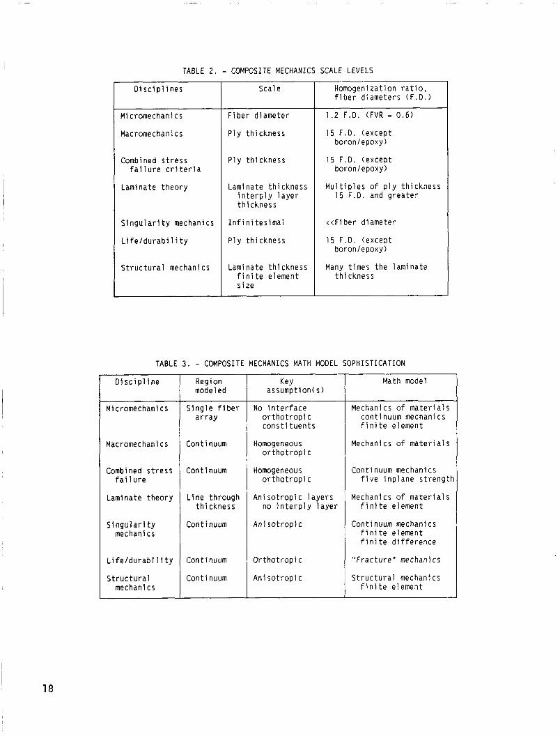
TABLE 2. - COMPOSITE MECHANICS SCALE LEVELS
D i s c i p l i n e s
Micromechanics
Macromechanics
Combined s t r e s s f a i l u r e c r i t e r i a
Laminate t h e o r y
S i n g u l a r i t y mechanics
L i f e l d u r a b i l i t y
S t r u c t u r a l mechanics
Scale
F i b e r d iamete r
Ply t h i c k n e s s
Ply t h i c k n e s s
Laminate t h i c k n e s s i n t e r p l y l a y e r t h i c k n e s s
I n f i n i t e s i mal
Ply t h i c k n e s s
Laminate t h i c k n e s s f i n i t e element s i z e
Homogenizat ion r a t i o , f i b e r d iameters ( F . D . )
1.2 F .D . ( F V R = 0.6)
15 F.D. (excep t boronlepoxy)
1 5 F.D. (excep t boronlepoxy)
M u l t i p l e s o f p l y t h i c k n e s s 15 F.D. and g r e a t e r
< < F i b e r d iameter
15 F .D . ( excep t boron/epoxy)
Many t imes t h e l a m i n a t e t h i c k n e s s
TABLE 3. - COMPOSITE MECHANICS MATH MODEL S O P H I S T I C A T I O N ~~ ~
D i s c i p l i n e
~
Micromechanics
Macromechani cs
Combined s t r e s s f a i 1 u r e
Laminate t h e o r y
S i n g u l a r i t y mechanics
L i f e l d u r a b i 1 i t y
S t r u c t u r a l mec han i c s
Region modeled
S i n g l e f i b e r a r r a y
Cont inuum
Cont inuum
L i n e th rough t h i c k n e s s
Cont inuum
Con t i nuum
Continuum
Key assumpt ion(s)
No i n t e r f a c e o r t h o t r o p i c cons t i tuen t s
Homogeneous o r t h o t r o p i c
Homogeneous o r t h o t r o p
Ani s o t r o p i c no i n t e r p
A n i s o t r o p i c
C
1 aye rs y l a y e r
O r t h o t r o p i c
A n i s o t r o p i c
Math model
Mechanics o f m a t e r i a l s cont inuum mechanics f i n i t e element
Mechanics o f m a t e r i a l s
Cont inuum mechanics f i v e i n p l a n e s t r e n g t h
f i n i t e element
Cont inuum mechanics f i n i t e element f i n i t e d i f f e r e n c e
" F r a c t u r e " mechanics
S t r u c t u r a l mechanics
Mechanics o f m a t e r i a l s
f i n i t e element
I 18
TABLE 4. - COMPOSITE MECHANICS
[Where has i t been? What has i t accomp l i shed? l
D i s c i p l i n e
Compos i t e
Compos i t e
Combined s t r e s s
Laminate t h e o r y
S i ngu l a r i t y mechanics
L i f e l d u r a b i 1 i t y
S t r u c t u r a l
m i cromechani cs
macromechanics
f a i 1 u r e
mechanics
Research conducted
Cons ide rab le
N e g l i g i b l e
Min imal
Cons ide rab le
S u b s t a n t i a l
S u b s t a n t i a l
Min imal
Success (understood/ q u a n t i f i e d )
~
P a r t i a1
Excep t iona l
N o t i c e a b l e
Acceptable
Promi s i ng
Promi s i ng
H i g h l y accep tab le
A p p l i c a t i o n
L i m i t e d
Ex tens i ve
Ex tens i ve
E x t e n s i v e
L i m i t e d
L i m i t e d
Ex tens i ve
TABLE 5 . - COMPARISON OF MEASURED AND PREDICTED ELASTIC PROPERTIES OF ANGLEPLIED LAMINATES
[AS/3531-5 w i t h 1.8 p e r c e n t m o i s t u r e and room tempera tu re . ]
Laminate
[0 /*452/0/+45Is
Measured
P r e d i c t e d
Percen t d i f f e r e n c e
1 0 2 / ~ 4 5 / 0 2 / 9 0 / 0 3 5
Measured
P r e d i c t e d
Percen t d i f f e r e n c e
[ ( 0 / * 4 5 / 9 0 ) 2 I s
Measured
P r e d i c t e d
Percen t d i f f e r e n c e
L o n g i t u d i n a l modulus, M S I
6.3
6.3
0
13.0
13.0
0
6.68
7.20
+7.8
Transverse modulus,
MS I
3.08
3.2
+3.9
4.2
4.5
+7.1
6.62
7.20
+8.7
Shear Modulus,
MS I
3.21
3.80
+18.4
1 . 5
1.6
+6.7
2.34
2.70
15.4
Ma jo r Poi sson ' s
R a t i o
0.803
.781
-2.70
0.325
.318
-2.2
0.350
f333
-4.8
19
TABLE 6 . - COMPARISON OF FRACTURE STRESSES
[The specimen was loaded t o f r a c t u r e i n combined a x i a l compression and t o r s i o n a l
l o a d i n g c o n d i t i o n . ]
S t r e s s type S t r e s s va lue , KSI
A x i a l
To rs i onal
Measured P r e d i c t e d
Lower bound Upper bound
20.2 17 .9 19.4
2 3 . 1 2 0 . 6 2 2 . 3
Notch type - 90
P l y o r i e n t a t i o n ; [&IS; e i n degrees
aLT = L o n g i t u d i n a l t e n s i o n . TT = Transverse t e n s i o n . S = I n t r a p l y shear.
Numbers denote f a i l u r e modes as f o l l o w s : ( 1 ) i n i t i a l f r a c t u r e due t o i n t r a p l y shear i n the
no tch t i p zone (2 ) minimal i n t r a p l y shear ing d u r i n g f r a c t u r e ( 3 ) some i n t r a p l y shear o c c u r r i n g near c o n s t r a i n t s
( g r i p s ) (4 ) de lamina t ions occur i n no tch t i p zone p r i o r t o any i n t r a p l y damage
I = I n t e r p l y de lamina t ion .
Unnotched -- s o l i d
Notched -- through s l i t
Notched -- through ho le
20
0 3 5
LT LT LT -- s3 s 3
s1 51 s1 LT LT LT
s1 s1 s1 LT LT LT
Mode Measured
1 62
2 190
3 288
4 42 5
5 6 6 7
TABLE 9. - COMPOSITE MECHANICS
[Where is it headed? Where should it go?]
Predicted Predicted/ measured
6 4 1.03
186 .98
3 0 3 1.05
4 5 4 1.01
6 5 3 .98
___
Di scipl i ne
Compos i te mi cromechani cs
Compos i te macromechanics
Combined stress fai 1 ure
Laminate theory
Singularity mechanics
Life/durabi 1 i ty
Structural mechanics
Effort/approach
Negligible
Negl i gi b 1 e
Negl igi ble
Nonl i near
(traditional)
(classical)
(classical )
(conventional)
Extensive homogeneous anisotropy (classical)
Progressive fracture (semi conventional)
Fami 1 iari ty with available GPFEC (user mode) limited FE development
Should go (personal view)
Fracture initiation and propagation
Combined mode fracture and mode tracking
In situ ply strengths and failure mode branching
Increase computational efficiency and three- dimensional behavior
Local heterogeneity and nonl ineari ty
Hygral, thermal, mechani- cal, and temporal aspects properly and tractably integrated
Development of composite mechanics specialty finite elements and substructuring methods
21
TAKEUP DRUM MONOMER SOLUTION
BROAD GOODS
I N SITU POLYMERIZATION
PL IES D I E
FIGURE 1. - PMR POLYIMIDE PROCESS.
FROM GLOBAL
ANALYSIS
COMPONENT TO GLOBAL STRUCTURAL STRUCTURAL
ANALYS I S /--- f ,I--- \
\ / 0 \
\ I' /'
/ I LAM1 NATE / \ I
I I \ \ \ \
\ \
LAMINATE \ / !-/z-!p I t THEORY
THEORY
LAMINATE \ / !-/z-!p I t THEORY
PLY
COMPOS I TE MICROMEC"""'rC THEORY - k -
IICS
/
I I
\ /
~ O P - D O W N CONSTITUENTS , ' TRACED
MATERIALS PROPERTIES P ( , T, M)
/ OR \
UPWARD INTEGRATED
"SYNTHESIS" I -------- "DECOMPOSITION" OR 'I.
BLADE
FIGURE 2. - ICAN: INTEGRATED COMPOSITES ANALYZER.
22
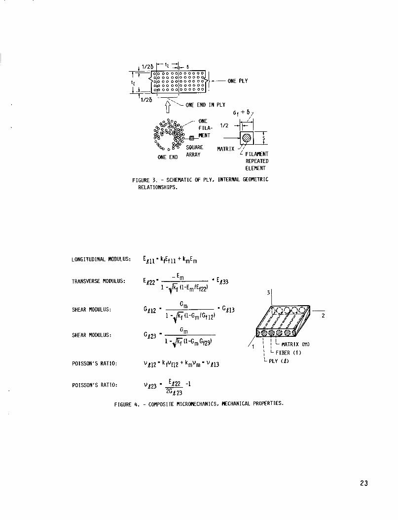
ONE END ARRAY
7 1
MATRIX ,! FILAMENT
REPEATED ELEMENT
FIGURE 3. - SCHEMATIC OF PLY, INTERNAL GEOMETRIC RELATIONSHIPS.
L T LONGITUDINAL TENSION TT TRANSVERSE TENSION IS I NTRALAMINAR SHEAR LF LONGITUDINAL FLEXURE TF TRANSVERSE FLEXURE L I LONGITUDINAL IMPACT T I TRANSVERSE IMPACT
FIGURE 20. - 3-D PLY AND INTERPLY STRESS FIELDS AS THE FREE EDGE IS APPROACHED (+20°PLY. Ck201 AS/E LAM I NATE 1 .
33
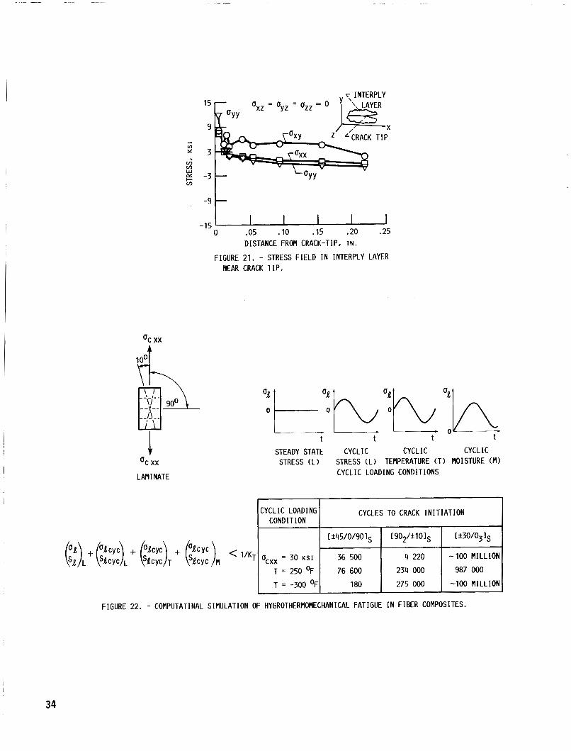
15
9 LCRACK T I P
I
v)
* 3 v) v)
2 -3 5
CYCLIC LOADING CONDITION
Ucxx = 30 K S I
T = 250 OF
T = -300 OF
-9 t
CYCLES TO CRACK I N I T I A T I O N
c*45/0/90 1 [ 9O2/fl 01s [+30/03 Is
36 500 4 220 -100 M I L L I O N
76 600 234 000 987 000 180 275 000 -100 M I L L I O N
0 -05 -10 .I5 -20 .25 DISTANCE FROM CRACK-TIP. I N .
FIGURE 21. - STRESS F I E L D I N INTERPLY LAYER
-15
NEAR CRACK T I P .
t I t t STEADY STATE CYCLIC CYCLIC CYCLIC
STRESS (L) STRESS (L) TEMPERATURE ( T ) MOISTURE (M) CYCLIC LOADING CONDITIONS
F IGURE 22. - COMPUTATINAL S IMULATION OF HYGROTHERMOMECHANICAL FATIGUE I N F I B E R COMPOSITES.
34
(a ) NO LOAD. (b) LOAD EQUAL APPROXIMATELY ONE-HALF FRACTURE LOAD.
C-SCAN RECORD
G
0 SELECT CRITICAL "G" AND CRITICAL "a"
C-SCAN RECORD CODSTRAN
INTERCHANGE
__ _ _ _ _ _
I
12 000
10 000
8 000 m d
d 6 000 4 0 2
4 000
2 000
0
2 a = 0.625
NOTE: CRACK OPENING DIS- PLACEMENT BETWEEN A AND B
I ,001 .002 .003 ,004 .005
CRACK OPENING DISPLACEMENT, I N .
FIGURE 23. - CODSTRAN PREDICTED RESULTS COMPARED WITH EXP DATA.
0 DETERMINE REQUISITE PROPERITIES AT DESIRED CONDITIONS USING COMPOSITE MICROMECHANICS
0 RUN 3-D F I N I T E ANALYSIS ON ENF ("F) FOR AN ARBITRARY LOAD
0 SCALE LOAD TO RATCH INTERLAMINAR SHEAR STRESS AT ELEMENT NEXT TO CRACK-TIP
0 WITH SCALED LOAD EXTEND CRACK AND PLOT STRAIN ENERGY RELEASE (GI VERSUS CRACK LENGTH (a )
EXTENDED CRACK LENGTH. a
0 METHOD HAS VERSATILITY/GENERALITY
FIGURE 24 . - GENERAL PROCEDURE FOR PREDICTING COMPOSITE INTERLAMINAR FRACTURE TOUGHNESS USING THE END-NOTCH-FLEXURE (ENF) OR MIXED- MODE-FLEXURE (NNF) METHOD.
35
5
4
3
2
1
0
-1 . a 1
17.0
r MIDSPAN DEFLECTION ( W )
, .
MODE / - GLOBAL MIXED ( I & 11) ----- LOCAL MIXED ( I & 11) --- LOCAL I
A 0' -----/@
i /i i
MODE / / - GLOBAL MIXED ( I & 11) ----- LOCAL MIXED ( I & 11) --- LOCAL I
A 0' -----/@ -- LOCAL 1 1
I I 1.2 1.3 1 1.1
EXTENDING CRACK-TIP DISTANCE. I N .
FIGURE 25. - MIXED-MODE-FLEXURE ENERGY RELEASE RATE AND COMPONENTS (ASIE).
36
LOCAL TRANSVERSE q- BORON TORSIONAL STRENGTHENING P L I E S 7 / / I STIFFENING PLIES
/ I / 1 ' ; , .
GRAPHITE/ KEVLAR CENTR I FUGAL AND FLE URAL LOAD P L I
Mechanics o f Composite M a t e r i a l s : Pas t , P resen t , and Fu tu re
NASA TM-100793 4. Title and Subtitle 5 . Report Date
10. Work Unit No.
7. Author@)
C h r i s t o s C. Chamis
I 505-63-1 1
8. Performing Organization Report No.
E-3936
9. Performing Organization Name and Address
N a t i o n a l A e r o n a u t i c s and Space A d m i n i s t r a t i o n Lewi s Research Center C leve land , O h i o 44135-3191
' iber-composi t e s ; Resin-matr ices; I n t e r p l y h y b r i d s : n t r a p l y h y b r i d s ; M i cromechani cs; Combi ned-stress a i l u r e : Laminate t h e o r v , S i n q u l a r i t v mechanics;
11. Contract or Grant No.
~
U n c l a s s i f i e d - U n l i m i t e d S u b j e c t Category 24
13. Type of Report and Period Covered
9. Security Classif. (of this report)
Uncl a s s i f i ed
~~ 1 Techn ica l Memorandum 2. Sponsoring Agency Name and Address
20. Security Classif. (of this page) 21. No of pages 22. Price'
Uncl ass i f i ed 40 A03 ,
N a t i o n a l A e r o n a u t i c s and Space A d m i n i s t r a t i o n Washington, D.C. 20546-0001
14. Sponsoring Agency Code
~
~~
5. Supplementary Notes
Presented a t t h e 2 1 s t Annual Mee t ing o f t h e S o c i e t y for E n g i n e e r i n g Science, B lacksburg , V i r g i n i a , October 15-17, 1984. I n v i t e d paper .
6. Abstract
Composite mechanics d i s c i p l i n e s a r e p resen ted and d e s c r i b e d a t t h e i r v a r i o u s l e v e l s o f s o p h i s t i c a t i o n and a t t e n d a n t sca les o f a p p l i c a t i o n . C o r r e l a t i o n w i t h exper imen ta l d a t a i s used as t h e p r ime d i s c r i m i n a t o r between a l t e r n a t i v e methods and l e v e l o f s o p h i s t i c a t i o n . Ma jo r emphasis i s p l a c e d on: ( 1 ) where composi te mechanics has been; ( 2 ) what i t has accompl ished; ( 3 ) where i t i s headed, based on p r e s e n t r e s e a r c h a c t i v i t i e s ; and ( 4 ) a t t h e r i s k o f b e i n g presumptuous, where i t shou ld be headed. The d i s c u s s i o n i s developed u s i n g s e l e c t e d , b u t t y p i c a l examples o f each compos i te mechanics d i s c i p l i n e i d e n t i f y i n g degree o f success, w i t h r e s p e c t t o c o r r e l a t i o n w i t h exper imen ta l d a t a , and problems rema in ing . The d i s c u s s i o n i s c e n t e r e d about f i b e r i r e s i n composi tes drawn m a i n l y from t h e a u t h o r ' s r e s e a r c h a c t i v i t i e s / e x p e r i e n c e spanning two decades a t Lewis .
7. Key Words (Suggested by Author@)) I 18. Distribution Statement
i f e / d u r a b i l i t y ; F r a c t u k e toughness:-Damage t o l e r a n c e ; ' r o g r e s s i v e f r a c t u r e ; S t r u c t u r a l a n a l y s i s ; n v i ronmental e f f e c t s