I 2004 5th Asian Control Conference I Design of Decentralized Power System Stabilizers for I Multimachine Power System using Model Reduction and I Fast Output Sampling Techniques ! I I Rajeev Gupta", B.Bandyopadhyay* and A.M.Kulkarni+ *Systems and Control Engineering, Email: [email protected], [email protected]Indian Institute of Technology Bombay, Mumbai INDIA -400 076 , Indian Institute of Technology Bombay, Mumbai INDIA - 400 076 I +Department of Electrical Engineering, 1 Email: ani1Oee.iitb.ac.h I Abstract Power System Stabilizers (PSSs) are added to excitation systems to enhance the damping during low frequency oscillations. In this paper, the design of decentralized PSSs for 10 machines with 39 buses using fast output sampling feedback via reduced order model is proposed. The nonlinear model of multimachine system is linearized at a particular operating point and a linear model is obtained. Using model reduction technique, lower order model is obtained from the higher order model and for this reduced model a stabilizing state feedback gain is obtained. Using aggregation technique, state feedback gain is obtained for the higher order model, A decentralized fast output sampling feedback gain which realizes this state feedback gain is obtained using LMI approach. This method does not require state of the system for feedback and is easily implementable. This decentralized fast output sanipIing control via reduced order model is applied to non-linear plant model of the multimachine. This method gives very good results for the design of Power System Stabilizers. Keywords: Decentralized control, fast output sampling feedback, multimachine system, nonlinear simulation, power system stabilizer, reduced order model. 1 INTRODUCTION Power System Stabilizers are added to excitation systems to enhance the damping of electric power system during low frequency oscillations. Several methods are used for the design of PSSs. Tuning of supplementary excitation controls for stabilizing system modes of oscillations has been the subject of much research during the past 35 years [l]. Two basic tuning techniques have been successfully utilized with power system stabilizer applications: Phase compensation method and the Root locus method. A commonly used approach is based around the conventional PSS structure which is composed of a wash out circuit and a cascade of two-phase lead networks. A number of PSS input signals, such as terminal voltage, rotor speed, accelerating power, electric power etc., and linear combinations of these have been extensively investigated and recommendations regarding their use have 1 been reported in the literature. Phase compensation consists of adjustment of the stabilizer to compensate for the phase lags through the generator, excitation system and power system, such that, the stabilizer path provides torque changes which are in 'phase with the speed changes [2] - [4]. This is the most straightforward approach, easily understood and implemented in the field and is most widely'used. The design of such PSSs requires the determination(or tuning) of few parameters for each machine viz. the overall dc gain, the wash out circuit time constant, and the various constants for the two-lead netyorks. A number of sequential and simultaneous approaches for tuning of these parameters have been reported in literature[5] - 171. Although the above approaches have been used and have produced satisfactory Tesults regarding the damping of local modes of oscillation, their outcome may not be considered the best possible. This is because of the restrictive assumptions made and the intuitive nature of the design process IS]. Synthesis by root locus involves the shifting of eigenvalues associated with power system 'modes of oscillation, by adjusting the stabilizer pole and zero locations in the s-plane 191. This approach gives an additional insight to the performance, by working directly with the closed-loop characteristics of the systems, as opposed to the open loop nature of the phase compensation technique. But it is more complicated to apply, particdrly in the field. hiloreover, the performance of these stabilizers considerably degrades with the changes in I I I I 1384 Authorized licensed use limited to: INDIAN INSTITUTE OF TECHNOLOGY BOMBAY. Downloaded on December 4, 2008 at 04:59 from IEEE Xplore. Restrictions apply.
Transcript
I 2004 5th Asian Control Conference
I
Design of Decentralized Power System Stabilizers for I Multimachine Power System using Model Reduction and
I Fast Output Sampling Techniques !
I I
Rajeev Gupta", B.Bandyopadhyay* and A.M.Kulkarni+ *Systems and Control Engineering,
Indian Institute of Technology Bombay, Mumbai INDIA -400 076
,
Indian Institute of Technology Bombay, Mumbai INDIA - 400 076 I
+Department of Electrical Engineering, 1
Email: ani1Oee.iitb.ac.h I
Abstract
Power System Stabilizers (PSSs) are added to excitation systems to enhance the damping during low frequency oscillations. In this paper, the design of decentralized PSSs for 10 machines with 39 buses using fast output sampling feedback via reduced order model is proposed. The nonlinear model of multimachine system is linearized at a particular operating point and a linear model is obtained. Using model reduction technique, lower order model is obtained from the higher order model and for this reduced model a stabilizing state feedback gain is obtained. Using aggregation technique, state feedback gain is obtained for the higher order model, A decentralized fast output sampling feedback gain which realizes this state feedback gain is obtained using LMI approach. This method does not require state of the system for feedback and is easily implementable. This decentralized fast output sanipIing control via reduced order model is applied to non-linear plant model of the multimachine. This method gives very good results for the design of Power System Stabilizers. Keywords: Decentralized control, fast output sampling feedback, multimachine system, nonlinear simulation, power system stabilizer, reduced order model.
1 INTRODUCTION
Power System Stabilizers are added to excitation systems to enhance the damping of electric power system during low frequency oscillations. Several methods are used for the design of PSSs. Tuning of supplementary excitation controls for stabilizing system modes of oscillations has been the subject of much research during the past 35 years [l]. Two basic tuning techniques have been successfully utilized with power system stabilizer applications: Phase compensation method and the Root locus method.
A commonly used approach is based around the conventional PSS structure which is composed of a wash out circuit and a cascade of two-phase lead networks. A number of PSS input signals, such as terminal voltage, rotor speed, accelerating power, electric power etc., and linear combinations of these have been extensively investigated and recommendations regarding their use have 1 been reported in the literature. Phase compensation consists of adjustment of the stabilizer to compensate for the phase lags through the generator, excitation system and power system, such that, the stabilizer path provides torque changes which are in 'phase with the speed changes [2] - [4]. This is the most straightforward approach, easily understood and implemented in the field and is most widely'used. The design of such PSSs requires the determination(or tuning) of few parameters for each machine viz. the overall dc gain, the wash out circuit time constant, and the various constants for the two-lead netyorks. A number of sequential and simultaneous approaches for tuning of these parameters have been reported in literature[5] - 171. Although the above approaches have been used and have produced satisfactory Tesults regarding the damping of local modes of oscillation, their outcome may not be considered the best possible. This is because of the restrictive assumptions made and the intuitive nature of the design process IS].
Synthesis by root locus involves the shifting of eigenvalues associated with power system 'modes of oscillation, by adjusting the stabilizer pole and zero locations in the s-plane 191. This approach gives an additional insight to the performance, by working directly with the closed-loop characteristics of the systems, as opposed to the open loop nature of the phase compensation technique. But it is more complicated to apply, par t icdr ly in the field. hiloreover, the performance of these stabilizers considerably degrades with the changes in
I
I
I
I 1384
Authorized licensed use limited to: INDIAN INSTITUTE OF TECHNOLOGY BOMBAY. Downloaded on December 4, 2008 at 04:59 from IEEE Xplore. Restrictions apply.
the operating condition during normal operation. It is also known that for a multimachine system, eigenvalue assignment is often too involved and complex for simultaneous stabilization of multivariable systems and may not provide satisfactory results for sequential multivariable systems applied as SISO systems. Not much attempts have been made for designing the power system stabilizers for multimachine power system using multivariable control theory. The complexity stems from the fact that insufficient degree of freedom is available to the designer in assigning eigenstructure by fixed gain output feedback method. Moreover, even if a sufficient degree is available or a dynamic output feedback stabilizer is sought, numerical problems often arise regarding the solution of sets of high dimensional nonlinear algebraic equations, for which a solution may or may not exist. It is also well known that, in application of multivariable Nyquist array methods to multimachine power system, many difficulties arive for the attainment of necessary diagonal dominance condition [lo].
Since the eigenvalue assignment and Nyquist array approaches have proved to be cumbersome, modern control methods have been used by several researchers to take advantage of the optimal control techniques. These methods utilize a state space representation of power system model and calculate a gain matrix which when applied as a state'feedback control will minimize a prescribed objective function. Successful application of the optimal control to power system stabilizers requires that the constraints imposed by power system nonlinearities be used effectively and that a Limited number of feedback signals be included [ l l ] . As a result, reports have appeared in the literature concerning the application of LQR theory for the design of power system stabilizers(PSSs). First LQR theory was applied to single machine infinite bus(SM1B) system. Later, this was extended to multimachine case. It is quite easy t o realize that neither of these approaches can be successful while dealing with real-life power systems which, in general, may have thousands of state variables [12]- [13]. The reason is that all the states may not be available for measurement or may be difficult to measure. In this case, the optimal control law requires to design the state observer. This increases the implementation cost and reduces the reliability of control system. Another disadvantage of the observer based control system is that, even slight variations of the model parameters from their nominal values may result into significant degradation of the closed loop performance. Hence, it is desirable to go for an output'feedback design method.
In recent years there have been several attempts at designing power system stabilizer using H, based robust control techniques [14]- 1151. In this approach, the uncertainty in the chosen system is modeled in
terms of bounds on frequency response. A H, optimal controller is then synthesized which guarantees robust stability of the closed loop system. Other performance specifications such as disturbance attenuation criteria are also imposed on the system. However, it should be noted that the main objective of using a PSS is to provide a good transient behaviour. Guaranteed robust stability of the closed loop, though necessary, is not adequate as a specification in this application. In addition to this, the problem of the poorly damped pole-zero cancellations and the choice of weighting functions used in design, limit the usefulness of this technique for PSS design. H, design, being essentially a frequency domain technique does not provide much control over transient behavior and closed loop pole location. It would be more desirable to have a robust stabilizer which, in addition guarantees an acceptable level of small signal transient performance. Moreover, this will lead t o dynamic output feedback, which may be feasible but leads to a higher order feedback system WI. The static output feedback problem is one of the most investigated problems in control theory. The complete pole assignment and guaranteed closed loop stability is still not obtained by using static output feedback [17]. Another approach to pale placement problem is to consider the potential of time-varying fast output sampling feedback. With Fast output sampling approach proposed by Werner and Furuta [IS], it is generically possible to simultaneously realize a given state feedback gain for a family of linear, observable models. This approach requires to increase the low rank of the measurement matrix of an associated discretized system, which can be achieved by sampling the output several times during one input sampling interval, and constructing the control signal from these output samples. Such a control law can stabilize a much larger class of systems than the static output feedback [19]-[22]. In fast output sampling feedback technique gain matrix is generally full [ZO], This results in the control input of each machine being a function of outputs of all machines, Centralized fast output sampling feedback PSSs require transmission of signal among the generating units. This requirement in itself no longer constitutes a problem from practical and technical view points. This is due to the rapid advancement in optical fiber communication and their adoption by power utilities. However, if a completely decentralized PSS can be found so that no significant deterioration in the system performance is experienced compared to state and centralized fast output sampling feedback based schemes, then such a scheme would be more advantageous, in terms of practicability and reliability. In such schemes not only is the cost implementation drastically reduced but also the risk of loss of stability due to signal transmission failure is minimized[23]. Also due to
1385
Authorized licensed use limited to: INDIAN INSTITUTE OF TECHNOLOGY BOMBAY. Downloaded on December 4, 2008 at 04:59 from IEEE Xplore. Restrictions apply.
the geographically distributed nature of power system, the decentralized control scheme may be more feasible than the centralized control scheme. In decentralized power system stabilizer, the control input for each machine should be function of the output of that machine only. This can be achieved by designing a decentralized PSS using fast output sampling feedback technique in which the gain matrix should have all off-diagonal terms zero or very small compare to diagonal terms. In decentralized PSS, to activate the proposed controller at the same instant, proper synchronization signal is required to be sent to all machines. Thus, the decentralized stabilizer design problem can be translated into a problem of diagonal gain matrix design for multi machine power system[24]. For a large power system, the order of the state matrix may be quite large. I t would be difficult to work with these complex systems in their original form [25]. In particular to compute the state feedback gain needed to obtain the decentralized fast output sampling feedback based power system stabilizer becomes very tedious for a large power system. One of the ways t.0 overcome this difficulty is to develop a reduced order model for a large power system. Then a state feedback gain can be computed from the reduced model of the power system and using aggregation techniques, a state feedback gain can be obtained for the higher order (actual) model. This paper proposes the design of a power system stabilizer for multi machine system using fast output sampling feedback via reduced order model. A brief outline of the paper is as follows: Section 2 presents basics of power system stabilizer whereas Section 3 contains the modeling of multi machine system. Section 4 presents a brief review on decentralized fast output sampling feedback control method. Section 5 contains the simulations of multi machine at different operating points with the proposed controller followed by the concluding section.
2 Power System Stabilizers
Implementation of a power system stabilizer implies adjustment of its frequency characteristic and gain to produce the desired damping of the system oscillations in the frequency range of 0.2 to 3.0 Hz. The transfer function of a generic power system stabilizer may be expressed as
where K, represents stabilizer gain and the stabilizer Gequency characteristic is adjusted by varying the time constant T,, Tl,Tz,T3 and T4.
A power system stabilizer can be made more effective if it is designed and applied with the knowledge of associated power characteristics. Power system
I
stabilizer must provide adequate damping for' the range of frequencies of the power system oscillation modes. To begin with, simple analytical models, such as that of a single machine connected to an idinite bus, can be useful in determining the frequencies of local mode oscillations. Power system stabilizer should also be designed to provide stable operation for the weak power system conditions and associated loading. Designed stabilizer must ensure for, the robust performance and satisfactory operation with an external system reactance ranging fmm 20% to 80% on the unit rating [26].
3 Multimachine Power System Analysis
Analysis of practical power system involves! the simultaneous solution of equations consisting of synchronous machines and the associated excitation system and prime movers, interconnecting transmission network, static and dynamic load (motor) loads, and other devices such as HVDC converters, static var compensators. The dynamics of the machine rotor circuits, excitation systems, prime mover' and other devices are represented by differential equations. The result is that the complete system model consists of large number of ordinary differential and algePraic equations [27]. I
Model 1.0 is assumed for synchronous machines by neglecting damper windings. In addition, the following assumptions are made for simplicity [28]. 1
I 1. The loads are represented Iiy constant impedances.
2. Transients saliency is ignored by considering xq= xd. 1
3. Mechanical power is assumed to be constant.
4. Efd is single time constant AVR.
I I
I
3.1 Generator equations The machine equations ( for kth machine ) are
j
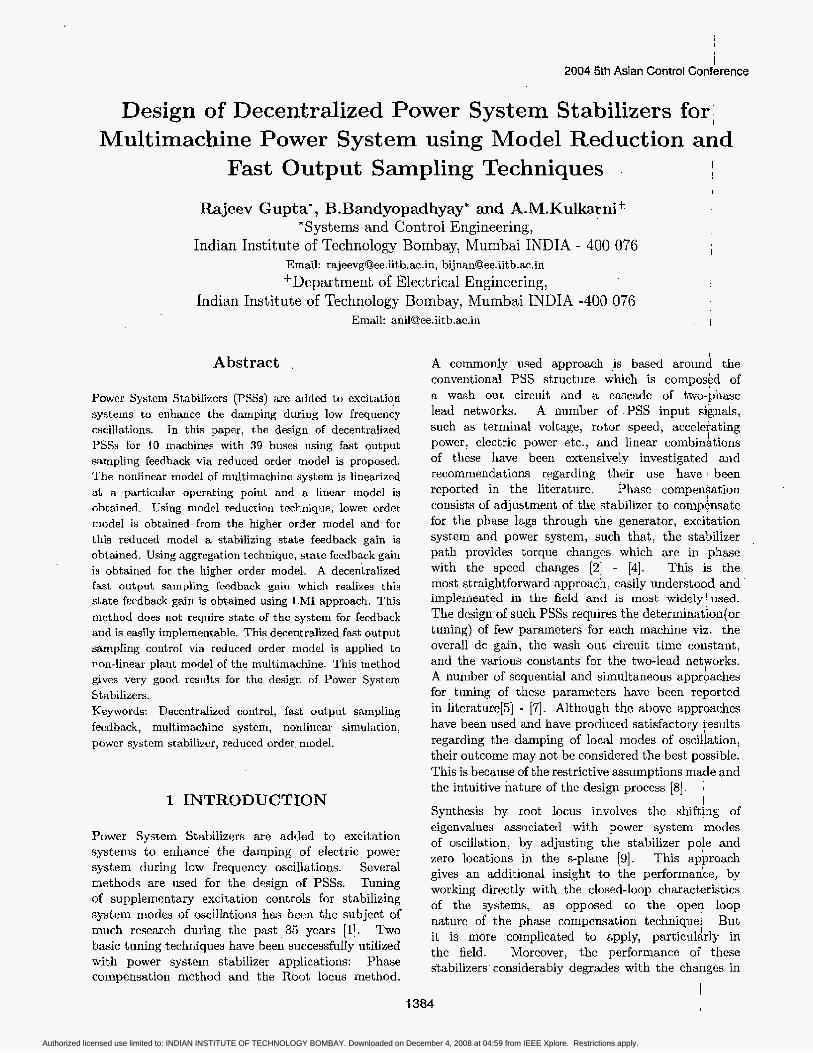
3.2 State space model of multi machine system The state space model of a 10-machine 39 bus system as shown in Fig. 1 can be obtained using machine data, line data and load flow as given in [28] as
Authorized licensed use limited to: INDIAN INSTITUTE OF TECHNOLOGY BOMBAY. Downloaded on December 4, 2008 at 04:59 from IEEE Xplore. Restrictions apply.
43
Figure I: Block diagram of 10 machine an
where
39 bus System
xk (k=l, lO) denotes the states of kth machine, and Yk
(k=1,10) denotes the output of the k th machine.
The elements of network parameters.
matrix depend on the machine and
4 On Fast Output Sampling Feedback
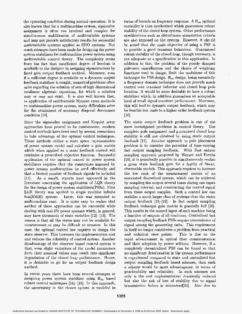
4.1 Review on Fast Output Sampling Feedback The problem of pole assignment by fast output sampling was studied by Werner and Furuta [IS]. It was shown that fast output sampling feedback technique has the features of static output feedback and makes it possible to arbitrariIy assign the system poles. Unlike static output feedback, fast output sampling feedback always guarantees the stability of the closed loop system. In fast output sampling, each sampling period T is subdivided into N subintervals A = r / N . N must be chosen greater than or equal to the observability index. The Iast N output samples are measured at the time instant t = lA, 1 = 0,1, . . . and a constant control signal is applied over a period 7. The control signal is constructed as a linear combination of the last output samples. Since the feedback gains are piecewise constant, their method could easily be implemented and indicated a new possibility. The method i s explained briefly in the following.
Figure 2: Fast output sampling feedback method
Consider a plant described by a linear model
X= AX + Bu, ( 7)
7J = cx, (8)
with (A, B)controllable and (C, A) observable. Assume the plant is to be controlled by a digital controller, with sampling time T and zero order hold, and that a sampled data state feedback design has been carried out to find a state feedback gain F such that the closed loop system
(9) IC ( k ~ + T ) = (aT + r,F)3: ( k ~ ) ,
has desired properties. Hence !DT = eAT and = !;eAs ds B. Instead of using a state observer, the following sampled data control can be used to realize the effect of the state feedback gain F by output feedback. Let A = T / N , and consider
1 Y W - A ) 1 (10)
for kr 5 t < (k + l)r> where the matrix blocks Lj represent output feedback gains, and the notation L, gk has been introduced for convenience. Note that 1/r is the rate at which the loop is closed, whereas output samples are taken at the N-times faster rate I/A. This control law is illustrated in Fig.2.
To show how a fast output sampling controller (10. ) can be designed to realize the given sampled-data state feedback gain, we construct a fictitious, lifted system for which (10 ) can be interpreted as static output feedback. Let ( @,I',C ) denote the system (8) at the
1387
Authorized licensed use limited to: INDIAN INSTITUTE OF TECHNOLOGY BOMBAY. Downloaded on December 4, 2008 at 04:59 from IEEE Xplore. Restrictions apply.
rate l /A . Consider the discrete-time system having at time t = k~ the input ub = u ( k ~ ) , state 21, = z (k . r ) and output as
T dominant eigenvalues, by truncating the systems. Using Eqn.(24) and Eqn.(25), we get,
Yk+l = C O Z k + D O U k , (12)
where CO and Do is the same as defined in [19].
Assume that the state feedback gain F has been designed that ((a, + r ,F) has no eigenvalues a t the origin. Then, assuming that in intervals kr 5 t < kT + T
U ( t ) = FZ(kT) , (13)
one can define the fictitious measurement matrix
above
C ( F , N ) = (CO -t DoF)(@., + (14)
which satisfies the fictitious measurement equation yk = C x k . For L to realize the effect of F , it must satisfy
LC = F. (15)
Let I/ denote the observability index of (@,I?). It can be shown that for N 2 v , generically C has full column rank, so that any state feedback gain can be realized by a fast output sampling gain L.
If the initial state is unknown, there will be an error A uk = ?&- Fxk in constructing the control signal under state feedback. One can verify that the closed loop dynamics are governed by
'
[ Xk+I ] = [ @ T + r r F AUkf l 0 LDo-Fr, ] [ F u k ] '
(16) Thus, one can say that the eigenvalues of the closed loop system under a fast output sampling control law (10) are those of @T -t r,F together with those of
The controller obtained from the above equation will give desired behavior, but might require excessive control action. To reduce this effect we relax the condition that L exactly satisfy the above linear equation and include a constraint on the gain L. Thus we arrive at the following inequations
L D ~ - m,.
This can be formulated in the framework of Linear Matrix Inequalities as follows [19]
In this form, the LMI Toolbox MATLAB can be' used for synthesis [29]. 1
4.2 Model reduction ! It is usually possible to describe the dynami'cs of physical systems by a number of simultaneous linear differential equations with constant coefficients $s
5 = Ax + Bu. (19)
The simulation and design of controllers become very cumbersome if the order of the system goes !high. One way to overcome this difficulty is to develop a reduced model of the higher order system. One of the well known technique is based on dominant eigenvalue retention. this is explained in the following section.
Let us consider a plant defined by I
I
The discrete time invariant systems with sampling interval T sec can be represented as 1
1
There exists a transformation V such that, ~
I
2 = vz, I (23)
transforms the above system into the following) block modal form 1
where,
Authorized licensed use limited to: INDIAN INSTITUTE OF TECHNOLOGY BOMBAY. Downloaded on December 4, 2008 at 04:59 from IEEE Xplore. Restrictions apply.
4.3 state feedback gain and decentralized fast output sampling feedback controller gains Let U(.) = STzT be a stabilizing control for the reduced order model in Eqn.(26). Thus closed loop reduced model (@I + l?lST) becomes stable. Now,
+% = [I. Or*(n-r,] 2, (27) = [I , : v - h
Therefore, we get,
u(k ) = s, [ I T : 0,*,,-,)] v-lz, (28) sx,
nrhich makes the closed loop systems ( Q T +I',S) stable and has no eigenvalues at the origin. Thus S F is the stabilizing state feedback gain for the system in Eqn.(22).
Using this F , If LMI constraints given in Eqns.(l7-18) are solved, fast output sampling feedback controller gain matrices may become full[ZO]. This results in the control input of each machine being a function of outputs of all machines. Due to the geographically distributed nature of power system and lack of communication' system (unavoidable delays), the decentralized control scheme may be more feasible than the centralized control scheme. Decentralized fast output sanipling feedback control can be achieved by making the off diagonal elements of LO, L I , . . . , Ljv-1 matrices zero.
With this structure of Li , the problem can be formulated in the framework of Linear Matrix Inequalities using Eqns.( 17-18) and the desired matrices can be obtained. Now it i s evident that the control input of each machine is a function that machine only and this makes the fast output sampling based power system stabilizer design a decentralized one[24]. In decentralized PSS,'to activate the proposed controIler at same instant, proper synchronization signal is required to be sent to all machines.
5 Case Study
The Nonlinear differential equations governing the behavior of a power system can be linearized about a particular operating point to obtain a linear model which represents the small signal oscillatory response of a power system.
The model of the 10 machine system as shown in Fig. 1 is considered for designing fast output sampling feedback controller using LMI approach of MATLAB software.
The following steps are used for the designing decentralized PSSs for the multimachine system using fast output sampling feedback method:
5.1 Linearization of multimachine power system and model reduction The 10 machines, 39 bus power system data are considered for designing fast output sampling feedback controIler via reduced order model using LMI approach of MATLAB. The single line diagram of the system is shown in Fig.1. The machine data, line data and load flow data are given[28].
The above multimachine power system is modeled using Simulink Toolbox, of MATLAB and a linear state space model is obtained for the same. Then discrete model obtained for sampling time T = 0.1 sec. The' reduced order model of order of 20 is computed from the discrete model as discussed in Section 4.
5.2 Computation fast output sampling feedback controIler gains via reduced order model Using the method discussed in Section 4, a stabilizing gain matrix S, (10 x20) via reduced order model can be obtained using LMI Toolbox. Using aggregation techniques, the state feedback gains F (10 x40) can be calculated for the higher order (actual) model.
Using this F , LMI constraints given in Eqns.(l7-18) are solved for different values of p l , p2 and ps to find the decentrdized gain matrix. L for the actual model. The decentralized fast output sampling feedback gain matrix L (10x100) via reduced order model is obtained as given in Appendix.
The closed loop responses under the control law €or linearized model is satisfactory and abIe to stabilize the outputs. The eigen values of (aN +T'LC) is found to be within the unit circle.
5.3 Simulation with Non-linear model A SIMULINK based block diagram including all the nonlinear blocks is generated using Eqns. (2-4) [as]. The slip of the machine is taken as output. The slip signal with decentralized gain L and a limiter is added to V,,f signal. This is used to damp out the small signal disturbances via modulating the generator excitation. The output must be limited to prevent the PSS acting to counter action of AVR. The disturbances considered i s a self clearing fault at different bus cleared after. 0.1 second. The limits of PSS output are taken as kO.1. In decentralized PSS, to activate the proposed controller at same instant, proper synchronization signal is required to send to all machines. All PSSs can be applied simultaneously to the respective machine.
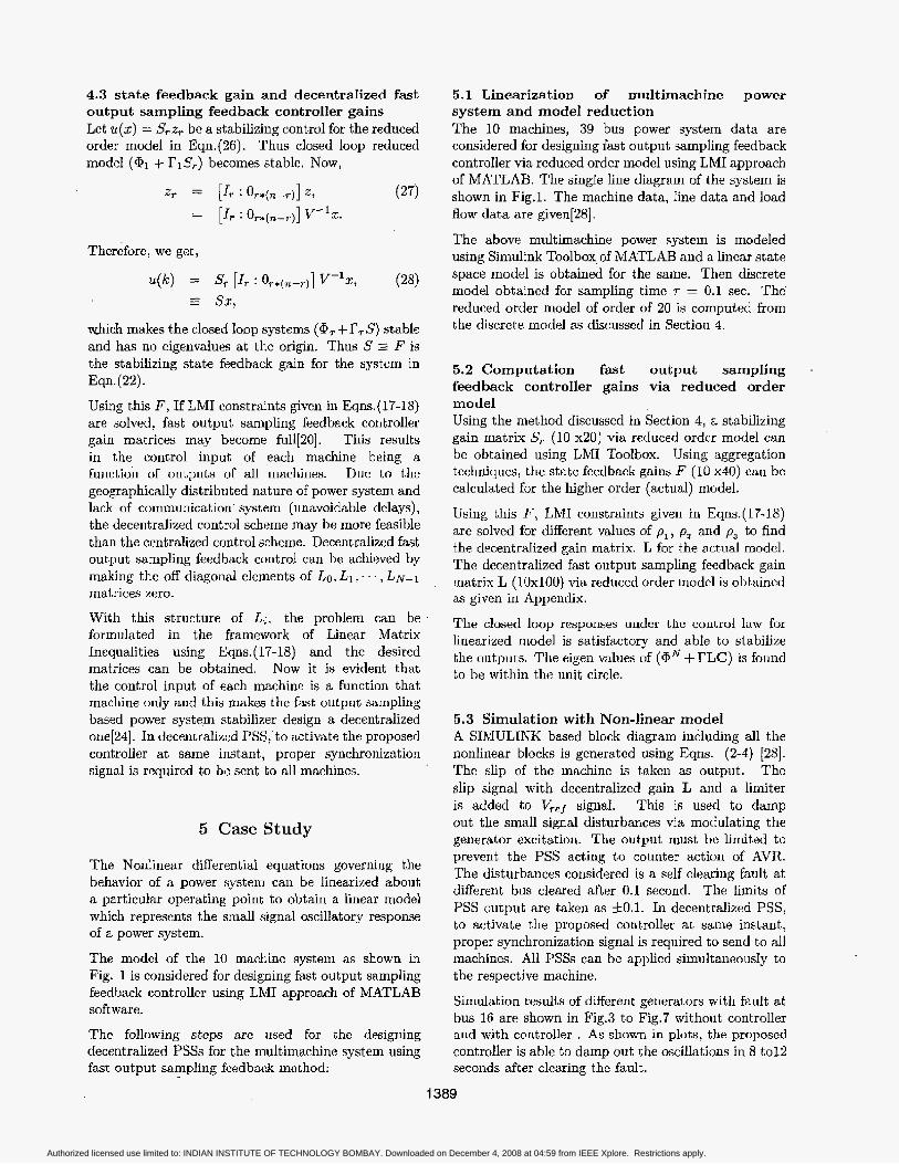
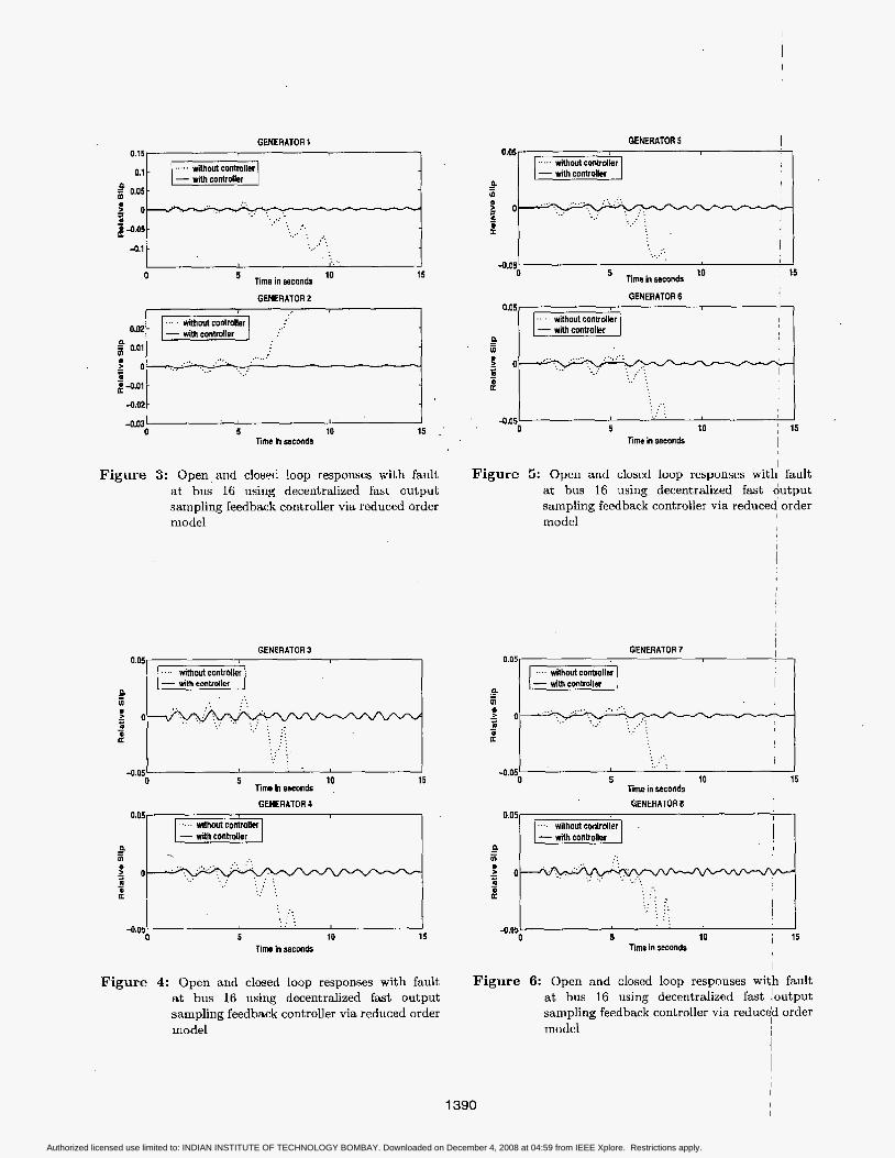
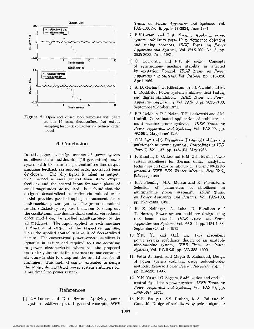
Simulation results of different generators with fault at bus 16 are shown in Fig.3 to Fig.7 without controller and with controller . As shown in plots, the proposed controller is able to damp out the oscillations in 8 to12 seconds after clearing the fault.
1389
Authorized licensed use limited to: INDIAN INSTITUTE OF TECHNOLOGY BOMBAY. Downloaded on December 4, 2008 at 04:59 from IEEE Xplore. Restrictions apply.
GENERATOR 1
n B 5 g h
-
-
-0.05
- with contrdler 0.05 I
:'..:.: . . . . . . . . . . . I
I
I
. . . . ..: . _ . , _ . . . . . . . . . . . . . .
0 0
I . . . ....
g -0.05
4.1 .' . . . . . . . * :
, : .
0.05 I
- wlth controller n
3 a 3
P
- - In ..................
. . . . . . . . .. _ : . m - i ,.,
. . . . . . . . . . .
I .. . . . . - . . I .
..I . 4.05
10 15 Timeinmancia 0
GENERATOR 2
m . . . . . . . . . . . . m 2 0
4.01
-0.02
. . . . . ...
. . I 0 5 10 15 "'
Time in sstmds
Figure 3: Open,and closed loop responses with fault Figure 5: Open and closed loop responses with fault at bus 16 using decentralized fast output at bus 16 using decentralized fast output sampling feedback controller via reduced order sampling feedback controller via reduced order model model
GENERATOR 3 0.05
.... without controller 1
I 0 5 10 15
lime in seconds
GENERATOR 4
. . . . . a . . . '. :. . . . t . . . . . . . .
0 5 10 15 Time in seconds
-0.05
Figure 4: Open and closed loop responses with fault at bus 16 using decentralized fast output sampling feedback controller via reduced order model
Figure 6: Open and closed loop responses with fault at bus 16 using decentralized fast !output sampling feedback controller via reduced order model
1
i
1390 I
Authorized licensed use limited to: INDIAN INSTITUTE OF TECHNOLOGY BOMBAY. Downloaded on December 4, 2008 at 04:59 from IEEE Xplore. Restrictions apply.
GENERATOR 9 0.05
I .. without controller 1
GENERATOR 10
-0.05 0 5 10 15
Time in seconds
Figure 7: Open and closed loop responses with fault at bus 16 using decentralized fast output sampling feedback controller via reduced order model
6 ConcIusion
In this paper, a design scheme of power system stabilizers for a multimachine( 10 generators) power system with 39 buses using decentralized fast output sampling feedback via reduced order model has been developed. The slip signal is taken as output. The method is more general than static output feedback and the control input for these plants of small magnitudes are required. It is found that the designed decentralized controller via reduced order model provides good damping enhancement for a midtimachine power system. The proposed method results satisfactory response behaviour to damp out the oscillations. The decentralized control via reduced order model can be applied simultaneously to the all machines. The input applied to each machine is function of output of the respective machine, Thus the applied control scheme is of decentralized nature. The conventional power system stabilizer is dynamic in nature and required to tune according to power characteristics where as, the proposed controller gains are static in nature and one controller structure is able to damp out the oscillations for all machines. This method can be extended to design the robust decentralized power system stabilizers for a multimachine power system.
References
[l] E.V.Larsen and D.A. Swann, Applying power system stabilizers part- I: general concepts, IEEE
Trans. on Power Apparatus and Systems, Vol. PAS-100, No. 6, pp. 3017-3024, June 1981.
[2] E.V.Larsen and D.A. Swann, Applying power system stabilizers part- 11: performance objective and tuning concepts, IEEfl Trans. on Power Apparatus and Systems, Vol. PAS-100, No. 6, pp. 3025-3033, June 1981.
[3] C. Concordia and F.P. de mello, Concepts of synchronous machine stability as affected by excitation Control, IEEE 5"s. on Power Appumtus and Systems, Vol. PAS-88, pp. 316-329, April 1969.
[4] A. D. Gerhart, T. HiIlesland, Jr., J.F. Luini and M. L. Rockfield, Power system stabiIizer field testing and digital simulation, IEEE Trans. on Power Appumtus und Systems, Vol. PAS-90, pp. 2095-2100, September/Octob er 19 71.
[5] F.P. DeMello, P.J. Nolan, T.F. Laskowski and J.M. Undrill, Ceordinated application of stabilizers in multi-machine power system, IEEE Trans. on Power Apparatus und Systems, Vol. PAS-99, pp. 892-901, May/June' 1980.
[6] C.M. Lim and S. Elangovan, Design of stabilizers in multi-machine power systems, Proceedings of IEE, Part-C,, Vol. 132, pp. 146-153, May'1985.
[7] P. Kundur, D. C. Lee and R.M. Zein El-din, Power system stabilizers for thermal units: analytical techniques and on-site validation, Paper FBO-227-9 presented IEEE PES Winter Meeting, New York, February 1980.
[8] R.J. Fleming, M.A. Mohan and K. Parvatisam, SeIection of parameters of stabilizers in multimachine power system" IEEE TrcLns. on Power Apparatus and Systems, Vol. PAS-100,
[9] K. E. Bollinger, A. Laha, R. Hamilton and T. Harras, Power system stabilizer design using root locus methods, IEEE Dam. on Power Apparatus and Systems, Vol. PAS-94, pp. 1484-1488, Sept ember/Oc t ober 1975.
[lo] Y.N. Yu and Q.H. Li, Pole placement power system stabilizers design of an unstable nine-machine system, IEEE Trans. on Power
[II] Fathi A. Saleh and Magdi S. Mahmoud, Design of power system stabjlizer using reduced-order methods, Electric P o w e r Sgstem Research, Vol. 33,
[12] Y.N. Yu and C. Siggers, Stabilization and optimal control signal for a power system, IEEE Trans. on Power Apparatus and Systems, Vol. PAS-90, pp.
1131 K.R. Padiyar, S.S. Prabhu, M.A. Pai and K. Gomitthi, Design of stabilizers by pole assignment
pp. 2329-2333, 1981.
Systems, Vol. PWRS-5, pp. 353-358, 1990.
pp. 219-226, 1995.
1469-1481, 1971.
1391 .
Authorized licensed use limited to: INDIAN INSTITUTE OF TECHNOLOGY BOMBAY. Downloaded on December 4, 2008 at 04:59 from IEEE Xplore. Restrictions apply.
with output feedback, Electric Power Systems Research, Vo1.2, No. 3,pp. 140-145, July'1980
[14] S. Chen and 0. P. Malik, H, based power system stabilizer design, IEE Proceedings p t . C, Vol. 142, No. 2, pp. 179-184, March 1995,
[IS] A. Soos and 0. P. Malik, An Hz Optimal adaptive power system stabilizer , IEEE Trans. on Energy Conversion, Vol. EC-17, pp. 143-149, March 2002,
[l6] P. Shrikant b o and I. Sen, Robust pole placement stabilizer design using linear matrix inequalities, IEEE Trans. on Power Systems, Vol. 15, No. 1, pp. 3035-3046, February 2000.
[17] V.L. Syrmos, C. adallah and P. Dorato, Static output feedback: A survey , Proceedings of the 33'd IEEE Conference on Decision and control, Lake Buena, Vusta FL(USA), Vol.VM-13 1:30, pp. 837-842, December'l994.
[lS] H.Werner and K.Furuta, Simultaneous stabilization based on output measurement,. Kybernetika, Vol. 31, pp. 395-411, 1995.
[19] H.Werner, Multimodel robust control by fast output sampling - LMI approach. Automatics, Vol.
[20] Rajeev Gupta, B. Bandyopadhyay and A.M.Kulkarni, Design of power system stabilizer for multimachine power system using fast output sampling feedback technique, 4 th Asian Control conference, ASCC2002, Singapore, pp. 1916-1921, September 2002.
[21j A.B.Chammas and C.T.Leondes, Pole assignment by piecewise constant output feedback, International Journal of Control, vol. 29, pp.
1221 B.M.Patre, B.Bandyopadhyay and H.Werner, Control of discrete two-time scale system by using piece constant periodic output feedback, Spstem Science,'Vol. 23, pp. 23-37, 1997.
[23] TVI. Aldeen and F. Crusca, Multimachine power system stabilizer design based on new LQR approach, IEE Proceedings of generation, transmission and distribution, Vol. 142, No. 6, pp.
[24] Rajeev Gupta, B. Bandyopadhyay and A.M.Kulkami, Design of Decentralized Power System Stabilizer for Multi-Machine Power System using Fast Output Sampling Feedback Technique, National Power System conference, NPSCZOO2, IIT Kharagpur (India), pp. 362-367.December 2002;
[25] E. J. Davison, A method for simplifying linear dynamic systems, IEEE Trans. o n Automatic Control, Vol.AC-11, pp. 93-101, January' 1966.
I261 E.V.Larsen and D,A.Swann, Applying power system stabilizers Part- 111: practical consideration,
34, No.2, pp. 1625-1630, 1998.
31-38,1979.
395-411, 1995.
IEEE Pans . on Power Apparatus and Systems; Vol. PAS-100, No. 6, pp. 3035-3046, June 1981.
[27] P.Kundur, Power System Stability and Control, McGraw-Hill, Inc., Newyork, 1993.
[28] K.R. Padiyar, Power System Dynamics Stability and Control, Interline publishing private 'Ltd., Bangalore, 1996.
[29] P.Gahenet, A.Nemirovski, A.J.Laub, and M.Chilali, LMI toolbox €or Matlab: user malnual,
1
The Math works Inc., Nutick MA, 1995. I
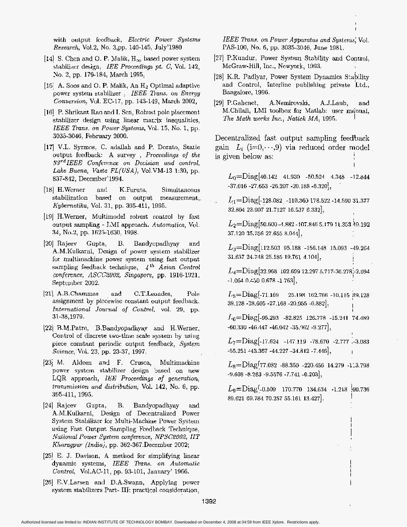
Decentralized fast output sampling feedback gain Li ( i d , . - . ,9) via reduced order model is given below as: I
Authorized licensed use limited to: INDIAN INSTITUTE OF TECHNOLOGY BOMBAY. Downloaded on December 4, 2008 at 04:59 from IEEE Xplore. Restrictions apply.