Project co-funded by the European Commission within the FP7 (2007–2013) Grant agreement no.: 308630 I-PAN I-PAN PROCESS AND TECHONOLOGICAL ARCHITECTUREL Project type: Collaborative Project Start date of project: 1 st October 2012 Duration: 36 months D2.2 I-PAN PROCESS AND TECHNOLOGICAL ARCHITECTURE WP n° and title WP2 - I-Pan Process and Technological Architecture WP leader IBL SPA Responsible Author(s) Marco Peschiera Contributor(s) CTECH, IMAL, STELA, IDP, ECSC, UMIL Planned delivery date M6 (03/2013) Actual delivery date M6 (03/2013) Reporting period RP1 Dissemination Level PU Public x PP Restricted to other programme participants (including the Commission Services) RE Restricted to a group specified by the consortium (including the Commission Services) CO Confidential, only for members of the consortium (including the Commission Services)
Transcript
Project co-funded by the European Commission within the FP7 (2007–2013) Grant agreement no.: 308630
I-PAN I-PAN PROCESS AND TECHONOLOGICAL ARCHITECTUREL
Project type: Collaborative Project
Start date of project: 1st October 2012 Duration: 36 months
D2.2 I-PAN PROCESS AND TECHNOLOGICAL ARCHITECTURE
WP n° and title WP2 - I-Pan Process and Technological Architecture
PP Restricted to other programme participants (including the Commission Services)
RE Restricted to a group specified by the consortium (including the Commission Services)
CO Confidential, only for members of the consortium (including the Commission Services)
D2.2 - I-Pan Process and Technological Architecture
Dissemination level - PU
I-PAN GA_NR.308630-REV.1.0 Page 2 of 57
Document information
Abstract
Wood is one of man’s most valuable resources and has been an important construction material throughout the history of mankind. In the engineered wood (EW) sector, Oriented Strand Board (OSB), which has replaced plywood over the last decades, has become the reference panel worldwide, accounting for 60% of the American and European EW markets. The downsides of the OSB panels are their relatively high density, making them unsuitable for lightweight applications, whilst state-of-the art binding resins are made using precursors from toxic or hazardous substances (e.g. like phenols, formaldehyde) and are cured at relatively high temperatures. Moreover, in the raw material collecting process, a large portion of the trees is wasted and not all OSB panels can be recycled. The OSB production footprint accounts for approximately 0,244 tCO2 per cubic meter of OSB.
The I-PAN project will provide a sustainable and viable alternative to OSB panels by employing a new type of light strand panels characterized by mechanical properties suitable for a wide range of applications. I-PAN aims to design a breakthrough lightweight wooden panel, adopting recycled wood for 50% of its volume and 50% poplar wood for the remainder utilizing the upper part of the tree that is commonly underused. Moreover, a novel manufacturing process will be designed and state-of-the-art resins will be innovated to achieve lower curing temperatures (~10%), thus minimizing volatile organic chemical (VOC) emissions and leading to a consistent reduction in production energy (~15%) and costs. The aforementioned advancements will be validated and will be the object of the so-called Life Cycle Assessment (LCA) analysis (Ciaotech-PNO).
In this deliverable, after an overview of the main objectives, the processes and state-of-the-art technologies will be analyzed, together with the I-PAN progress beyond the current state-of-the-art. We will then focus on the I-PAN processes themselves (i.e. drying, blending, mat forming) and the technological architecture. Such processes will be based on state-of-the-art OSB manufacturing and production chain and key elements will be innovated and designed in order to meet the challenging I-PAN objectives.
Keywords
Poplar, wood, osb, panels, engineered wood
Authors
Editor(s) Marco Peschiera
Contributors IDP, IMAL, CTECH,STELA
Peer Reviewers IDP;ECSC
D2.2 - I-Pan Process and Technological Architecture
Dissemination level - PU
I-PAN GA_NR.308630-REV.1.0 Page 3 of 57
Document history
Version Date Reviewed paragraphs Short description
0.1 13/01/2013 first First draft
0.2 14/02/2013 all Second draft
0.3 21/03/2013 All Release for peer review
1.0 29/03/2013 all Final version for the EC
* Abbreviations of editor/contributor name
D2.2 - I-Pan Process and Technological Architecture
Dissemination level - PU
I-PAN GA_NR.308630-REV.1.0 Page 4 of 57
TABLE OF CONTENTS
Contents
LIST OF ABBREVIATIONS AND DEFINITIONS 6
INTRODUCTION 7
1 STATE-OF-THE-ART OF THE MANUFACTURING OF OSB PANELS IN EUROPE AND GLOBALLY, AND NOVEL TECHNOLOGIES THAT WILL BE DEVELOPED 9
1.1 Overview 9
1.2 State of the Art in Engineered Wood 15
1.3 State of the Art in manufacturing processes 16
1.4 Progress beyond State of the Art 20
2 I-PAN PROCESSES AND TECHNOLOGIES 27
2.1 LOG DEBARKING AREA AND RECYCLED WOOD RECLAIM 27 2.1.1 technological innovations accomplished 28
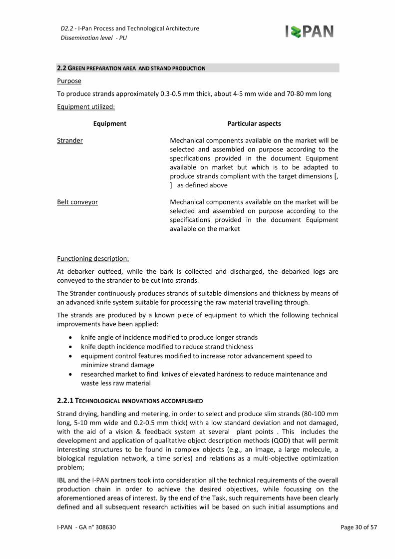
2.2 Green preparation area and strand production 30 2.2.1 Technological innovations accomplished 30
2.3 Strand storage green area 32
2.4 Strand drying and screening area 33 2.4.1 Technological innovations accomplished 34 2.4.2 Refining area and fine layer blending 35
2.5 Storage, preparation and dosing of the chemical components 37 2.5.1 Technological innovations accomplished 4039
2.6 Core and surface layer blending area 4241 2.6.1 TECHNOLOGICAL INNOVATIONS ACCOMPLISHED 4241
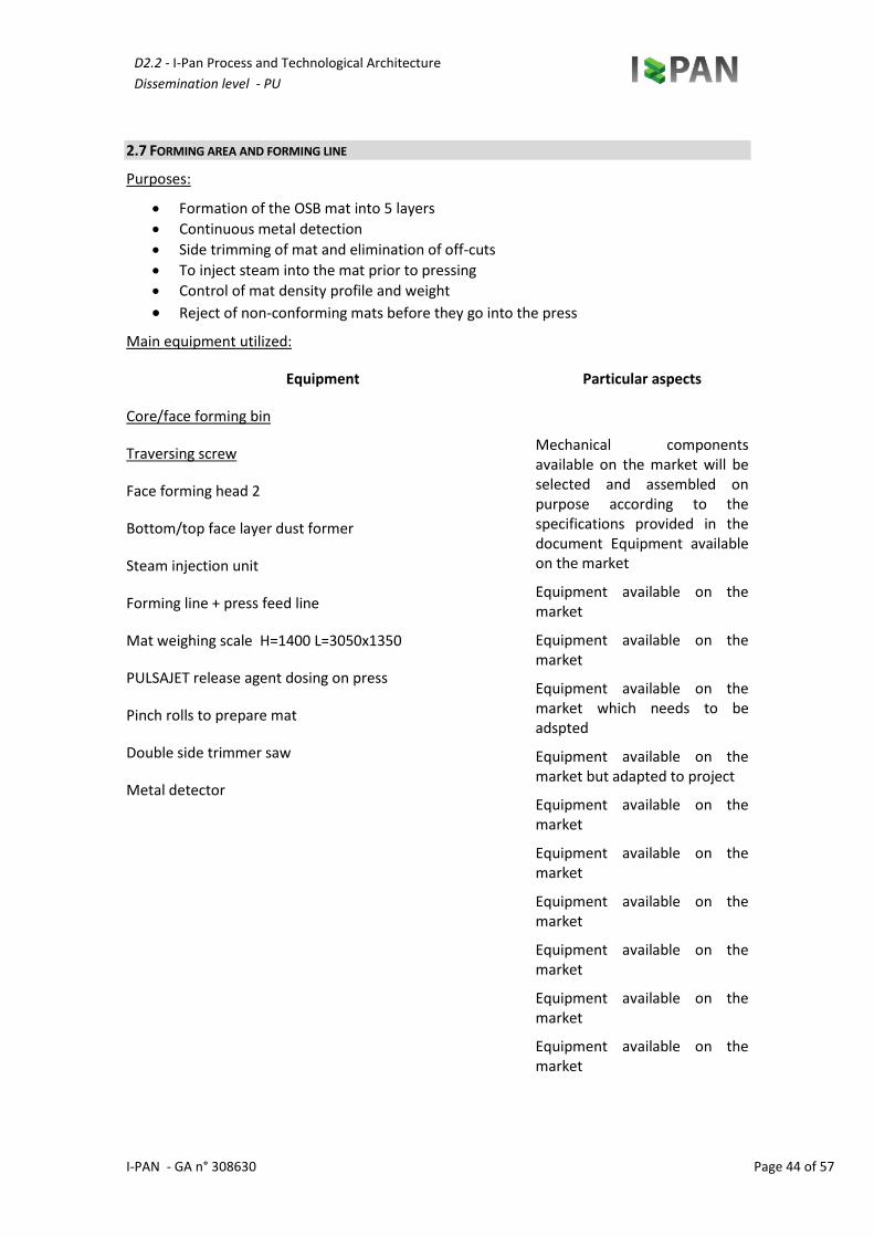
2.7 Forming area and forming line 4443 2.7.1 technological innovations accomplished 4544
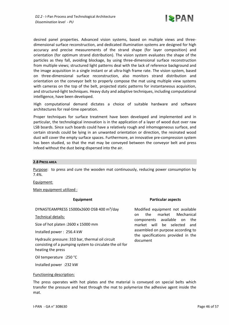
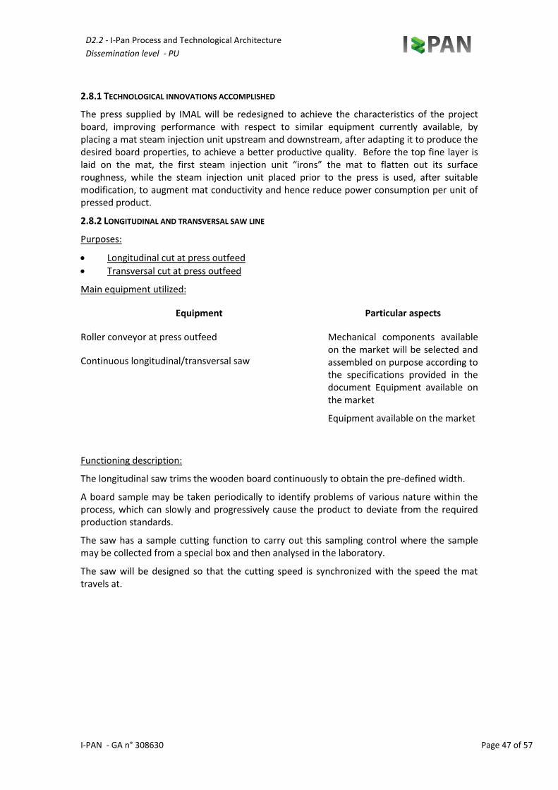
2.8 Press area 4645 2.8.1 Technological innovations accomplished 4746 2.8.2 Longitudinal and transversal saw line 4746
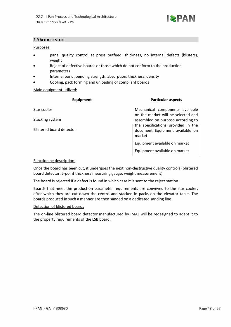
2.9 After press line 4847
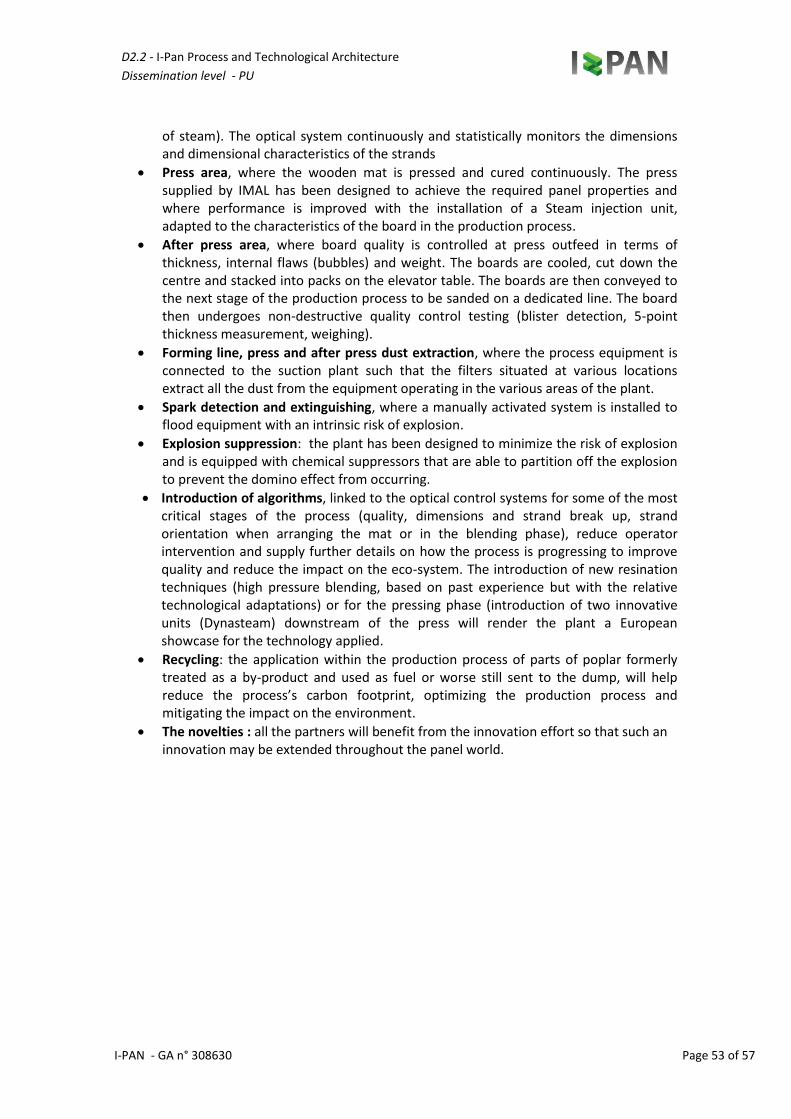
2.10 Forming line, press and after press dust extraction 4948
2.11 Spark detection and extinguishing area 5049
D2.2 - I-Pan Process and Technological Architecture
Dissemination level - PU
I-PAN GA_NR.308630-REV.1.0 Page 5 of 57
2.12 Explosion relief systems 5150
3 CONCLUSIONS 5251
4 BIBLIOGRAPHY 5453
LIST OF FIGURES
Figure 1. Blue areas (R&D Impacted areas), Orange Areas (main environmental benefits) ........................................10
Table 1 List of abbreviations...................................................................................................................................6
Table 3 I-PAN general flow sheet...........................................................................................................................53
Table 4 I-PAN recycles part flow sheet...................................................................................................................54
D2.2 - I-Pan Process and Technological Architecture
Dissemination level - PU
I-PAN - GA n° 308630 Page 6 of 57
LIST OF ABBREVIATIONS AND DEFINITIONS
Tabella 1List of abbreviations
DoW Description of Work
EC European Commission
PMQP Project Management and Quality Plan
WP Work Package
PMB Project Management Board
TMB Technical Management Board
PM Project Manager
DM Deliverable Manager
QM Quality Manager
PR Peer reviewer
D2.2 - I-Pan Process and Technological Architecture
Dissemination level - PU
I-PAN - GA n° 308630 Page 7 of 57
INTRODUCTION
Wood is one of man’s most valuable resources and has been an important construction material throughout the history of mankind. With the advent of the scientific and industrial revolution, the engineered wood (EW) sector has substantially progressed both in terms of higher quality wooden materials, and in terms of production and manufacturing, and panels and plywood represent about 12% of the total volume.
The woodworking industry is a very important sector in Europe, consisting of more than 100,000 companies, employing about 2 million people, thus accounting for nearly 2% of the manufacturing value added in Europe and in 2004 EU15 production totalled 45.6 million m3 (1).
The European Commission and the international policymakers are launching important actions taking into account that wood-based panels store CO2 and thus act as a carbon sink. At the last meeting of the Conference of the Parties to the Kyoto Protocol (COP 9), the international Conference stressed the importance to the political world of including wood-based products as carbon sinks under the Kyoto Protocol. An ambitious Roadmap 2010 study of the European Confederation of Woodworking Industries (CEI-Bois) has put together a challenging plan to make wood products the leading materials by the end of 2010. Such roadmap was based on two important assumptions: (i) forests and wood products (including wood-based panels) are important carbon sinks and (ii) 1 m3 of wood used in the building sector can reduce the CO2 emission from fossil fuels by up to 1,1 tonnes (2). Studies put forward four strategic implementation processes: Building with Wood, Living with Wood, Wood in Packaging and Transport, and Wood Products in Sustainable Development.
In this respect, wood-based panels have a relevant role and the I-PAN project aims at providing novel and highly environmental friendly solutions in the field of the engineered wood (EW) based boards.
The most important heavy EW in the market is the Oriented Strand Board (OSB) that, over the last decades, has replaced plywood in many sectors connected with the structural panel market, becoming basically the reference panel worldwide. Whenever lightness does not represent a critical advantage, OSB panels represent the material of choice, with highly appreciated properties.
In fact, OSB is employed in a variety of industrial sectors, ranging from the building sector, to the maritime industry and the recreational sector. OSB panels have the following main characteristics:
Easily engineered in terms of size, thickness, strand orientation and with a relatively large choice of adhesives, e.g. UF, PG, MF, MDI, PU resins, etc…
Uniform and flawless (gaps, core voids, holes).
Stable and durable.
Water-resistant (waterproofing can be achieved with additional membranes).
Desirable structural properties: high strength-weight ratio and rigidity.
Versatility: it can be employed for wall/roof sheeting, subfloors or single-layer floors and I-joists
Less costly than traditional plywood.
Within the market of traditional wood-based panels, lightweight boards represent a doable alternative to heavy EWs, when lightness is highly desirable.
The application of light boards though is not just restricted to furnishings and interiors as this type of wooden board is successfully employed in the building industry, marine and caravan
D2.2 - I-Pan Process and Technological Architecture
Dissemination level - PU
I-PAN - GA n° 308630 Page 8 of 57
construction and many others. There are three types of light board currently available on the market: (i) Traditional wood-based panels: panels made from veneers (plywood); (ii) Composite panels: panels made from wood particles and other lightweight, non-wood-based materials; (iii) Sandwich panels: panels made from several layers of materials and/or different structures.
The main challenge for the light wood-based panel industry is to reach higher level functional characteristics of Lightweight Strand Board (LSB) by engineering traditional wood based panels through innovations to the OSB manufacturing process as well as by continuously increasing the efforts to manage and use valuable resources in a sustainable manner throughout the entire life-cycle. Recovery and recycling of wood residues also form an integral part of the eco-efficient utilization of resources.
In such “Wood in Sustainable Development process”, light wood-based boards are an effective answer to today’s changing lifestyle thanks to the significant benefits for furniture manufacturers and their customers:
For manufacturers: decrease in raw material and transport costs, easier handling and a safer production process, optimized energy requirements, less expensive packaging.
For customers: lower purchase costs, improved ergonomics (packages lighter to carry, furnishings easier to assemble and carry around), better design.
In addition, the use of wood-based panels helps mitigate climate change by sequestrating carbon, not only during their primary lifetime, but beyond as well, since they can also be recycled. While the particleboard industry already took up this challenge some time ago, manufacturers have only recently started using recycled wood in their production processes.
The concept of the I-PAN project is to boost the utilization of traditional wood-based panels, by engineering their properties to match lightweight application requirements, reducing manufacturing costs along the overall process, allowing a highly sustainable approach at the same time. The virtuous circle allowing a sustainable manufacturing process will range from a reduction in raw material process input to the use of recycled material and minimisation of wastes along with innovative technologies enabling savings in energy consumption and reduction in pollutant compound emissions.
In this deliverable we will focus on the I-PAN processes and architecture. Key elements will be innovated, and they will consist of three main R&D areas:
i) Strand drying, handling and metering, in order to select and produce slim strands (80-100 mm long, 5-10 mm wide and 0.2-0.5 mm thick) with a low standard deviation and not damaged, with the aid of a vision & feedback system. This will include the development and application of qualitative object description methods (QOD) that will allow interesting structures to be found in complex objects (e.g. an image, a large molecule, a biological regulation network, a time series) and relations as a multi-objective optimization problem;
ii) Resins. The polymerization of the urea based resins shall guarantee higher moisture content in strands and low curing temperatures.
iii) Mat forming. Resins will need to be distributed on the strands in a well optimized way, minimizing resin utilization and VOCs.
All the technical requirements of the overall production chain are considered and clearly defined. These outcomes will be important for all subsequent research activities.
D2.2 - I-Pan Process and Technological Architecture
Dissemination level - PU
I-PAN - GA n° 308630 Page 9 of 57
1 STATE-OF-THE-ART OF THE MANUFACTURING OF OSB PANELS IN EUROPE AND GLOBALLY, AND NOVEL TECHNOLOGIES THAT WILL BE DEVELOPED
1.1 OVERVIEW
The present chapter will be focused on providing an overview of the main processes and technologies that will be employed. The processes will be based on state-of-the-art OSB manufacturing and production chain. In particular key elements will be innovated and designed in order to meet the I-PAN challenging objectives. They will consist of three main R&D areas while different partners are involved in the various innovation steps (see Figure 1.1):
1) Innovation in process steps dealing with strand drying, handling and metering by: i) Improving the quality of the drying process since a dry strand requires less glue and
makes the panel more resistant, reduce energy costs by recycling air into the flow, reducing the volatile organic compounds and reducing time. The novel I-PAN drying system will consist in a highly efficient process for drying strands with low-caloric heat. Low emissions as well as a high-quality final product will be the advantages of the STELA belt drier technology, characterized by low energy consumption.
ii) Obtaining top quality strands of given dimensions (80-100 mm long, 5-10 mm wide and 0.2-0.5 mm thick). This will be achieved in I-PAN by changing the inclination of the stainless steel blades, the speed at which wood is fed into the machine and rotor rotation speed inside the strander, which is responsible for strand production. Such a system will communicate with an optical recognition system that will send a feedback to the machine, in order to obtain strands of a well-defined dimension. The fact strands are not damaged and have a uniform dimensionality is of great importance for the mechanical properties of the boards, which must also meet OSB EN300 standard requirements. Moreover, by such a process optimization, the wood waste will be substantially reduced.
iii) Improving the process of handling, conveying and dosing of dried strands. Such strands shall not be damaged as they are produced after chipping in order to guarantee the best mechanical properties of the final product.
2) Polymerization at lower resin temperatures in order to reduce toxic elements in the emissions and reduce the cost of energy by: Developing a new formaldehyde-based resin suitable for bonding recycled wood and poplar strands to form LSB-type panels. The new resin will permit the production of LSB panels for structural use with low formaldehyde emissions satisfying the most stringent European Standards as per EN 13986. There will be a reduction in both formaldehyde emission during the production of the panels and the emissions from the finished panels, thus helping to protect the health of the working personnel and of the product’s end users. The new resin to be developed within the framework of I-PAN will cure/polymerize at temperatures of up to 10% lower than the conventional resins currently used. It will further be able to withstand strand moisture contents of over 3.5%. Thus the strand drying and mat hot-pressing processes of the panel production will be less energy-demanding, leading to a reduction in the energy consumption of the overall panel production process.
3) Innovations in the blending process and surface layer treatment for dust forming will greatly improve Mat Forming by:
i) Optimizing the consumption of resin and decreasing machine time for the same quantity of strands treated, thus reducing the energy consumption at the same output
D2.2 - I-Pan Process and Technological Architecture
Dissemination level - PU
I-PAN - GA n° 308630 Page 10 of 57
level. Traditionally, the same amount of resin is used for all strands and is a function of the time spent in the blender with major drawbacks of a great deal of waste and lack of efficiency in the production process. The innovation targeted in the blending process within the context of the I-PAN project is to achieve a more precise distribution of the resin on the strands to bring about a major benefit in terms of resin consumption reduction and energy saving during the blending process. The blending process will be improved by introducing new mechanical technologies on nozzles and blender engine, including image processing, as well as on software interoperability between the blender and the vision system. Dedicated monitoring systems are required for optimal resin distribution and specific treatments must be used for strands of different sizes. The monitoring system can also reduce possible strand damage due to an excessively long blending time. In the blending process, the high pressure system which injects the resin over a metered flow of strands, should also keep the equipment and the conveyors downstream to the gluing system cleaner. This will bring environmental benefits, i.e. less waste produced (wood waste + hardened glue) and attenuate problems related to operator health and safety in the unfortunate case of glue that might not have hardened completely, that might be more toxic and that might have stuck to the inner walls of the blender.
ii) A further relevant step in the mat forming process is related to the quality and accuracy of the strand orientation. Strand size and orientation must be controlled for each layer to obtain the desired panel properties for an optimized resin distribution. Control is influenced by many features that will be evaluated in real time. Such feature selection and measurement is made difficult by overlaps and colour similarities in strands, background patterns due to the conveyor belt, and the external environment, which is affected by dust, humidity, extreme temperatures, and glue residues. The quality and accuracy of strand orientation will be significantly enhanced by introducing advanced vision systems based on multiple views and three-dimensional surface reconstruction, and dedicated illumination systems will be designed for high accuracy and precise measurements of the strand shape (for layer composition) and orientation (for optimum strand distribution).
iii) Developing and testing a technological application for surface layer treatment, by exploiting the know-how acquired in other industrial sectors in order to achieve an innovative system for distributing a layer of wood dust over a raw board (mat).The aim of the dust forming process is to produce a layer of wood dust a couple of mm thick (2-5mm) on the two sides of the finished raw board starting from the mat forming process until the lamination of the finished raw board. Presently, a process of this kind has not been yet accomplished on an industrial scale. Such a process is complex as the wood dust will need to be produced in the mills, screened to obtain the right dust grains size and then resinated with urea-based resin and uniformly distributed on the top and bottom of the mat. The surface properties of the wood dust layer shall be such as to permit lamination of the raw board, after the pressing process, with various types of paper or other coating surfaces.
D2.2 - I-Pan Process and Technological Architecture
Dissemination level - PU
I-PAN - GA n° 308630 Page 11 of 57
OSB production has been widely assessed in the last 40 years, and only recently almost the entire panel board production has shifted to OSB. The growth of the OSB market has been substantial in the United States and Canada, but OSB plants are a l so operating in Europe and South America. Almost all the panels are used in structural applications in the same way as plywood. OSB characterised by greater bending strength along the panel direction (usually the parallel to the longest side) results in a product comparable to traditional plywood.
The materials employed are low-density hardwoods such as aspen and the like, but other species can be used, e.g. southern pine, lodgepole pine, jack pine, and scotch pine. High-density wood is still difficult to handle and cut and boards are relatively heavy. OSB is usually produced with a lower thickness, i.e. 11.1 or 12.7 mm, than wafer board used for similar applications. Such a reduced thickness thus permits a relatively large amount of material reduction in OSB manufacturing. Most OSB is now made with 75 mm strands or longer in the surface layers. The core can be made of smaller strands and can possibly be oriented. Today’s OSB panels are made with oriented layers (mostly three-layer [some with a randomly laid core], or five-layer constructions if needed) that are laid up similar to those in plywood. Moreover, OSB manufacturing allows the use of small and irregular logs, but straight 350mm diameter logs are generally preferred. In fact, logs are usually debarked with a ring-type debarker. Such debarking is very time consuming and inefficient with smaller logs. However, a large amount of the logs used are smaller in diameter. Drum debarkers specifically designed for smaller-diameter logs are also used for debarking smaller logs to prevent damaging the knives during the debarking operation.
The manufacturing process starts with the high-quality cut of wood flakes. This process requires green logs (50°C hot pond treatment might be required in cold climates). Most stranders are still of the disc type. New knife-ring flaker and disc machines have been developed to produce flakes from full-length logs without the need to slash the logs to lengths of about 900 mm long, as is required for feeding into the older disc flakers. The continued improvement of flakers will help the development of OSB. The material is then dried, and the finer material is screened out. Continuous pressing is also used in OSB manufacture, and steam-injection pressing, already used for particleboard, MDF, and PSL, might be considered.
Figure1 Blue areas (R&D Impacted areas), Orange Areas (main environmental benefits)
D2.2 - I-Pan Process and Technological Architecture
Dissemination level - PU
I-PAN - GA n° 308630 Page 12 of 57
This accelerates the pressing of phenolic-bonded panels, isocyanate-bonded panels, and 19 mm thick panels. Chemical modification of composites to provide dimensional stabilization has been proposed and performed, only to a limited degree. The major concern being expressed by the industry regards excessive thickness swell. In order to correct such issues steam treating is regarded as promising.
The resination process applied in traditional OSB panel production technology is normally carried out after the drying process, when the strands are weighed and fed into the blender. The blender consists of a large rotating drum (about 4 metres in diameter) inside which the material is blended with the resin. The glue mixture is sprayed through a set of spinning heads and the material is continuously mixed with the resin as the drum rotates. The drum is equipped inside with a set of paddles arranged in a radial manner over the entire length of the drum. The resined material is then conveyed to the forming line by suitable conveyors.
IMAL TECHNOLOGY
The traditional resination technology briefly described above has however the following major drawbacks:
Each spinning head is driven by an electric motor which is mounted inside the rotating drum. An elevated quantity of dust, naturally present in the material, tends to form within this enclosed environment, and an electric device running inside a dusty environment constitutes a potential ignition source which can cause serious damage to equipment and injury to persons.
The other major problem is caused by the rapid and excessive build up of dirt inside the blender, requiring frequent downtimes for cleaning operations. Resin and glued dust tend to settle in the gaps between the mixing paddles, filling them rapidly and which in time affects blending quality and performance. To avoid this problem, operators gradually increase drum rotation speed until the paddle gaps fill up completely and they have to stop the blender. Cleaning is generally a long and complex operation (about 8 hours) and the operators are forced to work in an unhealthy environment (volatile chemicals and powders).
To remedy the aforementioned issues and to achieve a significant reduction in the amount of consumed resin, IMAL has recently introduced an innovative resination concept, the core of which is a new concept blender equipped with a high pressure glue mixture injection system. The resination process takes place in three stages: distribution of the flow of material which is to be resined, application of the glue mixture and lastly the actual blending of the two. With the special accelerator rolls mounted at blender infeed, it is possible to achieve a fine and continuous flow of material with a large exposed surface area where the glue mixture is applied. In-house specifically designed injectors are used to apply the glue mixture, coupled with conventional sprayer terminals. This technology, which utilizes pump units operating over a pressure range of between 30 and 100 bar, produces an ideal nebulisation of the mixture that is carefully sprayed over the material flow through numerous injection points arranged directly over blender infeed. The resined material, then, enters in the second stage and in the blender, which consists of a fixed, outer, cylindrical casing, containing a rotating mixing shaft equipped with specially designed spirals, to achieve the best blending performance without damaging the material. It is possible to achieve significant resin savings with this new resination system (over 20% depending on the type of material) and to solve the problems encountered with traditional resination technology. There is absolutely no risk of a fire breaking out because there are no electrical devices operating inside a dusty environment and dirt build-up is greatly reduced with respect to the traditional blender thanks to the special
D2.2 - I-Pan Process and Technological Architecture
Dissemination level - PU
I-PAN - GA n° 308630 Page 13 of 57
blender lining which the material is able to slide over and which ensures that the blender is kept sufficiently clean.
DEVELOPMENT OF THE IMAL TECHNOLOGY
In view of the novel resination concept and its high potential, IMAL will address the glue mix injection process. Sometimes, state-of-the-art terminals are not flexible enough to control nebulisation pressure in relation to flow rate. In cases where glue flow rate is relatively low, it is necessary to reduce the number of active injection points to maintain the pressure required for optimal nebulisation, this though impacts on the blend of the glue mixture over the material. The aim of this research project is to design a new nozzle with a variable section orifice to achieve an accurate control of the nebulising pressure in relation to flow rate. We are confident that the design of such a nozzle will consent a further and significant decrease in the amount of glue mixture used in the process with evident benefits for the manufacturer.
The I-PAN project will focus on the innovation of the state-of-the art OSB manufacturing process by developing and improving the technologies supporting the different steps of the process with the final aim of producing a lighter and greener EW made of highly renewable resources, e.g. 50% selected poplar wood and 50% re-cycled wood.
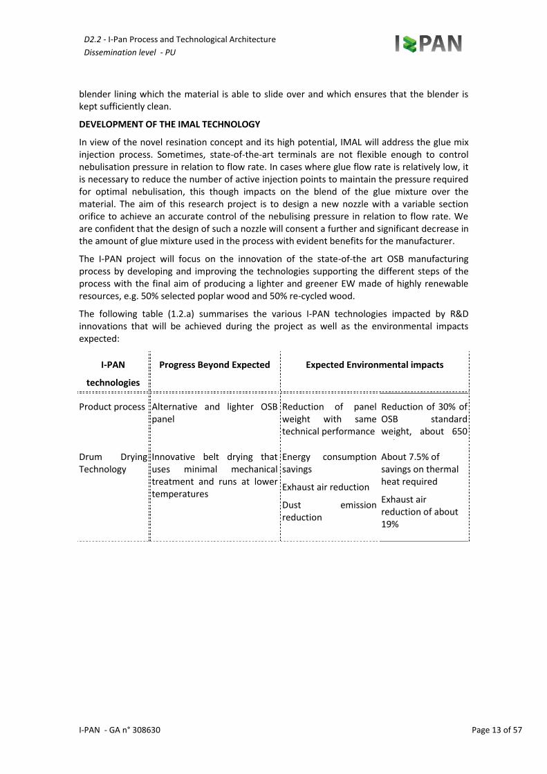
The following table (1.2.a) summarises the various I-PAN technologies impacted by R&D innovations that will be achieved during the project as well as the environmental impacts expected:
Reduction of panel weight with same technical performance
Reduction of 30% of OSB standard weight, about 650 kg/mc
Drum Drying Technology
Innovative belt drying that uses minimal mechanical treatment and runs at lower temperatures
Energy consumption savings
Exhaust air reduction
Dust emission reduction
About 7.5% of savings on thermal heat required
Exhaust air reduction of about 19%
19% Total dust emission
reduction at 10mg/Nm3
D2.2 - I-Pan Process and Technological Architecture
Dissemination level - PU
I-PAN - GA n° 308630 Page 14 of 57
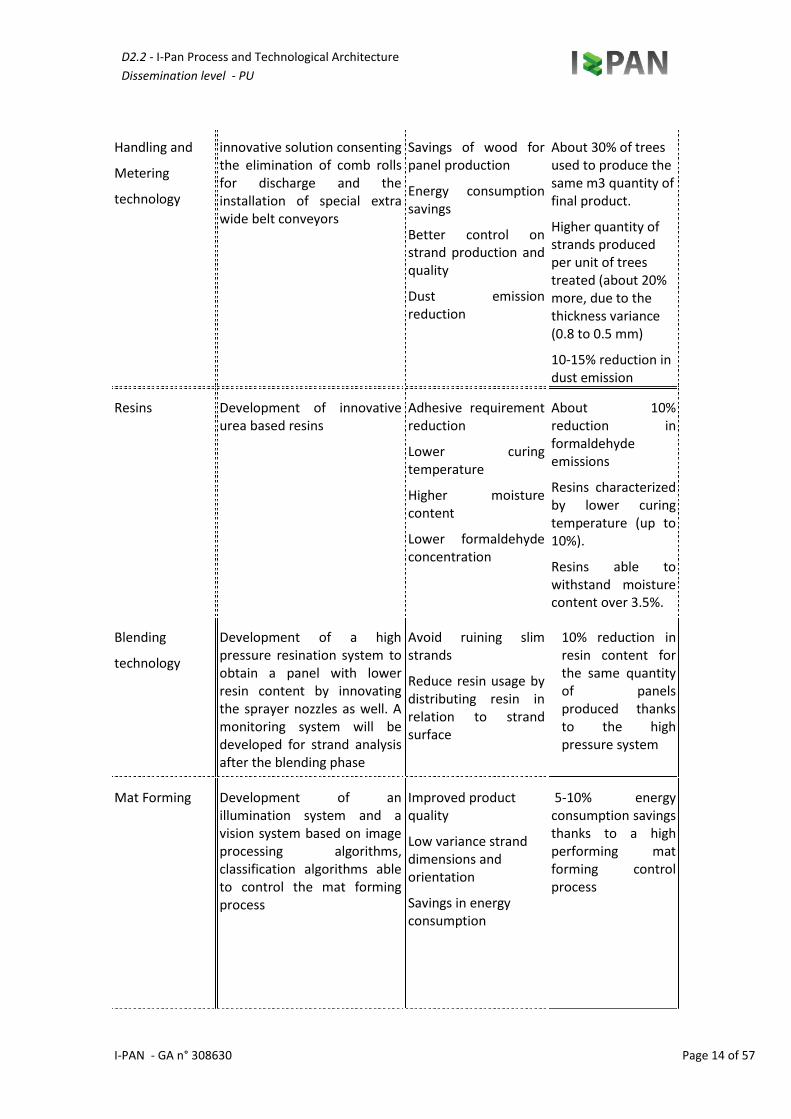
Handling and
Metering
technology
innovative solution consenting the elimination of comb rolls for discharge and the installation of special extra wide belt conveyors
Savings of wood for panel production
Energy consumption savings
Better control on strand production and quality
Dust emission reduction
About 30% of trees used to produce the same m3 quantity of final product.
Higher quantity of strands produced per unit of trees treated (about 20% more, due to the thickness variance (0.8 to 0.5 mm)
10-15% reduction in dust emission
Resins Development of innovative urea based resins
Adhesive requirement reduction
Lower curing temperature
Higher moisture content
Lower formaldehyde concentration
About 10% reduction in formaldehyde emissions
Resins characterized by lower curing temperature (up to 10%).
Resins able to withstand moisture content over 3.5%.
Blending
technology
Development of a high pressure resination system to obtain a panel with lower resin content by innovating the sprayer nozzles as well. A monitoring system will be developed for strand analysis after the blending phase
Avoid ruining slim strands
Reduce resin usage by distributing resin in relation to strand surface
10% reduction in resin content for the same quantity of panels produced thanks to the high pressure system
Mat Forming Development of an illumination system and a vision system based on image processing algorithms, classification algorithms able to control the mat forming process
Improved product quality
Low variance strand dimensions and orientation
Savings in energy consumption
5-10% energy consumption savings thanks to a high performing mat forming control process
D2.2 - I-Pan Process and Technological Architecture
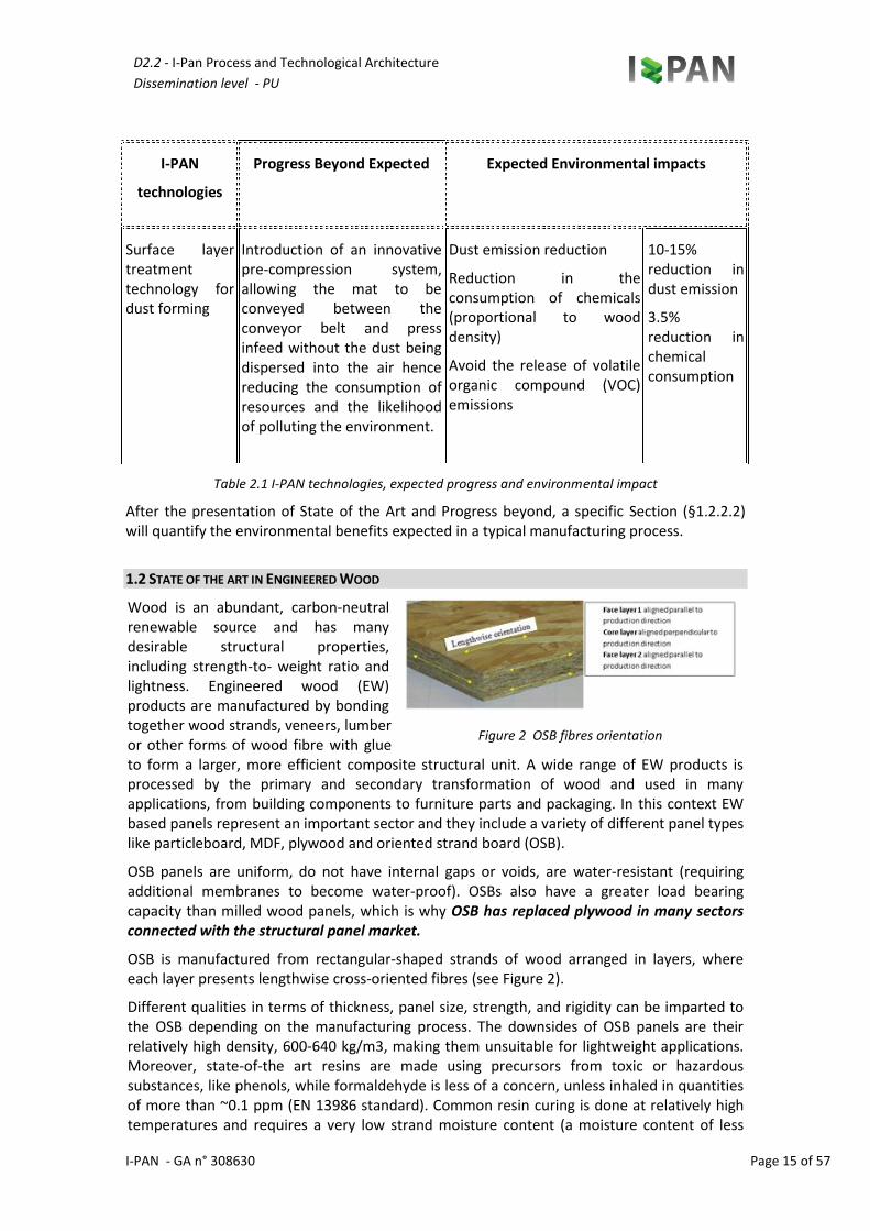
Surface layer treatment technology for dust forming
Introduction of an innovative pre-compression system, allowing the mat to be conveyed between the conveyor belt and press infeed without the dust being dispersed into the air hence reducing the consumption of resources and the likelihood of polluting the environment.
Dust emission reduction
Reduction in the consumption of chemicals (proportional to wood density)
Avoid the release of volatile organic compound (VOC) emissions
10-15% reduction in dust emission
3.5% reduction in chemical consumption
Table 2.1 I-PAN technologies, expected progress and environmental impact
After the presentation of State of the Art and Progress beyond, a specific Section (§1.2.2.2) will quantify the environmental benefits expected in a typical manufacturing process.
1.2 STATE OF THE ART IN ENGINEERED WOOD
Wood is an abundant, carbon-neutral renewable source and has many desirable structural properties, including strength-to- weight ratio and lightness. Engineered wood (EW) products are manufactured by bonding together wood strands, veneers, lumber or other forms of wood fibre with glue to form a larger, more efficient composite structural unit. A wide range of EW products is processed by the primary and secondary transformation of wood and used in many applications, from building components to furniture parts and packaging. In this context EW based panels represent an important sector and they include a variety of different panel types like particleboard, MDF, plywood and oriented strand board (OSB).
OSB panels are uniform, do not have internal gaps or voids, are water-resistant (requiring additional membranes to become water-proof). OSBs also have a greater load bearing capacity than milled wood panels, which is why OSB has replaced plywood in many sectors connected with the structural panel market.
OSB is manufactured from rectangular-shaped strands of wood arranged in layers, where each layer presents lengthwise cross-oriented fibres (see Figure 2).
Different qualities in terms of thickness, panel size, strength, and rigidity can be imparted to the OSB depending on the manufacturing process. The downsides of OSB panels are their relatively high density, 600-640 kg/m3, making them unsuitable for lightweight applications. Moreover, state-of-the art resins are made using precursors from toxic or hazardous substances, like phenols, while formaldehyde is less of a concern, unless inhaled in quantities of more than ~0.1 ppm (EN 13986 standard). Common resin curing is done at relatively high temperatures and requires a very low strand moisture content (a moisture content of less
Figure 2 OSB fibres orientation
D2.2 - I-Pan Process and Technological Architecture
Dissemination level - PU
I-PAN - GA n° 308630 Page 16 of 57
than 3.5%). Moreover, in the raw material collecting process, a large portion of the trees is wasted, while among the raw material employed in the manufacturing of the OSB panels, not all of them can be recycled for new OSBs. Furthermore the OSB production footprint accounts for approximately 0.244 tCO2 per cubic meter of OSB [3].
Lightweight boards represent a doable alternative to heavy EWs, when lightness is highly desirable. They have similar characteristics with respect to the existing panels, with the exception of the typology of the wood employed. Poplar is frequently the wood of choice for lightweight boards, whereas composites made of wood and synthetic polymers could be also used. Moreover lightweight boards are manufactured following the same main production steps as OSB, i.e. i) collection of raw wood; ii) gluing; iii) drying; iv) pressing. Current lightweight boards share many of the characteristics of OSB panels, in particular they present:
Density lower than 500 Kg/m3, compared to OSB density which is typically 600-680kg/m3.
Versatility for lightweight applications.
Desirable structural properties.
More specifically, typical lightweight boards include:
Composite boards made of wood particles and expanded polystyrene (EPS) balls, with a typical density of about 450 Kg/m3.
Full poplar plywood boards with a typical density of about 400 Kg/m3.
Sandwich boards characterized by honeycomb geometry and with a typical density of about 250 Kg/m3.
From market evidence, only full poplar plywood boards are suitable for most applications being very light and characterized by mechanical properties that may be used in a wide range of applications. However, they are costly and not easily engineered. On the environmental side, they utilize less adhesive than heavier boards but the amount of glue needed is still proportional to strand weight and not to strand surface. Such boards can be produced from certain parts only (mainly the lower part) of poplar trees, while the rest is wasted, and they cannot be fully recycled.
1.3 STATE OF THE ART IN MANUFACTURING PROCESSES
In state-of-the-art drying technologies, wet strands are fed into the drier at a moisture of approx. 60 %. First of all, the wet product is distributed over the belt width via two screw conveyors and is levelled. The strands are then fed into the drying zone by the belt motion. Inside the drier tunnel, hot air at a temperature of approx. 95 °C aerates through the strands. Fans provide the necessary ventilation for convective drying. In this way the final moisture is ultimately expected to be about 3%. Fines are separated from the strand layer itself by a filtering pad. The product is then shifted and mixed after half the drier length by means of a proven turning device in order to achieve a dried product as homogeneous as possible. These measures aim to guarantee an homogeneously dry product.
The current state-of-the-art of strand handling and metering systems is strongly affected by strand damage issues. After the drying process, wood strands for OSB production for both the surface and core layers are usually conveyed into storage systems, a bin with a rubber belt on the bottom. Conventional arrangements are normally equipped with a discharge system consisting of rotating discs fitted with cutting knives / milling cutters. Milling cutters can cut in two directions, namely conventional or climb milling:
• Conventional milling: chip thickness starts at a minimal thickness, and increases up to the maximum. The cut is so light at the beginning that the tool does not cut, but slides across
D2.2 - I-Pan Process and Technological Architecture
Dissemination level - PU
I-PAN - GA n° 308630 Page 17 of 57
the surface of the material, until sufficient pressure is built up and the tooth suddenly bites and begins to cut. This might deform the material, and dull the blades.
• Climb milling: each tooth of the cutter engages the material at a specific point, and the width of the cut starts at the maximum and decreases to a minimal thickness. The chips are arranged behind the cutter, leading to easier swarf removal. The tooth of the cutter does not rub on the material, thus blade life is longer.
However, such methodologies, involving scraping on the strands, could eventually tear them. Another factor worth considering is the ability of the cutters to remove swarf. If such swarf is not readily removed, the flutes might clog and prevent the cutting efficiency, overheat and wear the blades or knives. In this way there is considerable energy consumption and material waste.
Technology has changed sawmill operations significantly in recent years, emphasizing waste minimization and increasing energy efficiency as well as improving operator safety.
However, with the current technology, due to the energy demanding procedures and blade wear, there are difficulties in obtaining strands of the desired dimensions. Currently, the maximum admissible strand thickness is 0.7 mm, meaning higher wood consumption and heavier panels. A reduction in strand size could mean a considerable reduction in wood consumption (a 20% thickness reduction could lead to a 30% wood reduction) that will convert into economical and environmental benefits.
The current state-of-the-art of the blending process is accomplished with the application of various algorithms that take into account the type of resin and wood. Well-defined quantities of dry wood are analysed for specific moisture content (about 3%), which is proportional to the quantity of resins depending on the type of wood being used and the end product. The strands are mixed inside blenders, equipped with special nozzles mounted on the inside that inject the resin and additives, mixing them homogeneously with a helical motion. The blender blends the wood and resin together after which an even mat of material is formed and placed on a conveyor belt, ready for the pressing process. During this process the strands tend to break up and are not always uniformly covered with resin.
For some types of panels (e.g. MDF and Particleboard (PB), a high pressure blending system has been applied as well to reduce the amount of resin consumed, thus impacting on industrial costs by over 18% in the case of PB, and 30% in the case of MDF boards. This process has not yet been tested in the production of OSB, neither has it been tried with poplar wood as a raw material. The structure and angle of the nozzles used to spray the resin and additives are still a topic of research, where the aim is to find the best and most uniform distribution of the resin over the strands inside the blender.
Sprayers are currently mounted inside the blender and require continuous maintenance. Moreover performance is often affected because sprayers easily become dirty and in many cases, can be a source of ignition. The ratio between the resins and wood used in the blending process varies significantly in relation to various physical wood parameters (type, moisture content, size of strands or chips) and resins (urea, thermosetting resins, phenolformaldehyde (PF), natural resins and isocyanate), ranging between 3 and 20% of the wood. The blending process is critical for ensuring the quality of the OSB panels. Techniques for quality analysis can be divided into on-line and off-line methods: on-line methods are non-destructively integrated in the production process measuring a few properties, while off-line approaches can measure, possibly in a destructive way, many properties [10]. No solution has been presented in the literature to control strand properties accurately after blending, in particular
D2.2 - I-Pan Process and Technological Architecture
Dissemination level - PU
I-PAN - GA n° 308630 Page 18 of 57
by using image processing. Some works deal with the control of strand properties going into the blending phase and on their influence on the final product.
In literature, a five-class classification of strand shape and size before blending is presented by evaluating their effect on the mechanical properties of the final OSB panel [11], the strand area is measured from images at the stranding output to evaluate their shape at different temperatures before blending [12], neural networks are used for fast, accurate granulometry of falling strands by image processing [13] [14] . Many on-line systems for the analysis of OSB panels, in particular for strand orientation, have been presented by using computer vision approaches (e.g., [10] [15]) to measure strand size and orientation and detect pores.
No solution has been presented in the literature for the on-line monitoring of mat formation, in particular by using image processing. Partially related works assess strand properties, like angle and size, from images captured by CCD cameras. Some methods observe strand distribution during the production process and can be used to monitor mat formation and its final structure, such as: i) A line-detection method based on small eigenvalue analysis with Canny edge detectors
first identify the strands, while an elliptic fitting analysis then determines the fibre orientation [16].
ii) A comparison method using Fast Fourier Transform (FFT) and Filtered Image Analysis (FIA) [17] [18]
iii) A method to visually analyse the arrangement of strands [19] by observing the number of strands and area and orientation of each strand.
iv) A Computer tomography method (CT) used to detect the presence and size of pores in OSB panels [11], [20], [21], [22], [23].
v) A method that uses Bi-dimensional images [24]. vi) A method based on three-dimensional models [25] where void regions are estimated by
segmentation based on the Otsu algorithm and subsequent morphological operations. Voids ratio distribution along panel thickness is evaluated [26] by using CT and image binarization.
vii) A method of analysis of Macro-pores [11], [27]
As far as the state-of-art of the resins used in OSB process is concerned, it’s possible to refer to all the resins used in the chipboard industry: phenol-formaldehyde resins (PF), polymeric diphenyl methane diisocyanate (PMDI), melamine-formaldehyde (MF), melamine- urea-formaldehyde (MUF) and urea-formaldehyde (UF) resins. Uniform gluing of the large-area strands of OSB with small amounts of conventional liquid PF resin is difficult and for this reason, PF in powder form was the adhesive used in the early stages of OSB production in North America. Although this adhesive is more expensive, the low quantities employed (2 to 3% by weight based on dry strands) made its use acceptable. The liquid PF resins on the other hand, react faster and permit a higher moisture content of the finished board. By improving the elements of the manufacturing process, it was possible to reduce the amount of liquid resin needed. Thus, 3.5-4% of liquid resin load is required to obtain the same board quality as with 2-2.5% powder resin. Liquid phenolic resins also allow a higher resin load where special applications require a greater strength than that which powder resins can give. Powder resin does not adhere sufficiently to the strands and if more than 3% is added de-mixing occurs.
PMDI adhesives were promoted to overcome the dimensional instability of OSB panels after exposure of their edges to high moisture. These binders are more reactive than PF resins and help to achieve shorter press cycles (increased productivity). However, they have the disadvantage of sticking heavily to the press hot plates and the release agents developed to avoid this problem were not fully successful. This is why the isocyanate binders are normally used in the core layer of OSB together with phenolic resins, which are applied in the surface
D2.2 - I-Pan Process and Technological Architecture
Dissemination level - PU
I-PAN - GA n° 308630 Page 19 of 57
layers. The reactivity (cure factor) of the latter has increased considerably over the last few years, however it is still lagging behind when compared to UF, MUF and PMDI.
MUF and UF resins have also been employed in OSB production, however at levels higher than the previous adhesives (higher than 8% by weight based on dry strands). Straight MF resins are also commercially available for OSB, the current high price of melamine, however, makes them of no economic value to the OSB industry. Trials have also taken place with tannin resins, which are reactive and moisture resistant. More recently, MUPF resins have gained much attraction in Europe due to their potential of achieving the more demanding standards at an acceptable cost.
There is a difference between the resins employed in North America and Europe, which is mainly due to the different standards applied. In North America, OSB binders are either phenolic or PMDI based, whereas phenolic resins are supplied in either powder (PPF) or liquid (LPF) form and PMDI is supplied in liquid form only. Combinations of these two binder types are often employed and most commonly PMDI is used in the core, while PF is used in the surface layers of the panel to avoid the problems with panel stickiness on the press platens. In Europe apart from LPF, PPF and PMDI, melamine-urea-formaldehyde and melamine-urea-phenol-formaldehyde (MUPF) resins are readily applied. This difference in the OSB adhesives employed in North America and Europe is caused by the need to satisfy the stringent V100 test of EN 300. This demand cannot be satisfied by PPF, while economically unacceptable levels of LPF or PMDI are needed. Furthermore, increasing the phenolic resin level gives a dark colour to the boards. Hence, MUPF accounts for 50% of the OSB binder consumption in Europe, being used mainly in the surface layers with a tendency to replace PMDI usage in the core layers. Different adhesive formulations may be used for the surface and core layers. The amount of adhesive mix to be added is calculated starting from a solid adhesive substance to oven dry wood basis. The most commonly used adhesives are Urea-Formaldehyde (UF), melamine-urea formaldehyde resin (MUF), phenol formaldehyde (PF), Melamine-Urea-Phenol-Formaldehyde (MUPF) and the isocyanate-based adhesives (MDI).
Using UF resins is not without its disadvantages. UF is not weather resistant, which precludes use outdoors. Also, it releases formaldehyde, controversially classified as carcinogenic by the International Agency for Research on Cancer (IARC) as of 2004 but currently classified as 3-R40 substance, i.e. limited evidence of carcinogenic effects, by the European Union.
Since regulations like EN 13986 limit the maximum concentration of formaldehyde in the air, this can restrict the number of indoor uses for boards bonded with such a resin. The moisture resistance of UF can be improved by fortifying it with melamine to form a MUF resin. These adhesives are clear and strong, but are more costly. PF resins on the other hand are much more weather resistant and do not have the same issues as formaldehyde does. Admittedly, they are more expensive, being approximately twice the price of UF resins. Higher temperatures and longer time periods are required to cure PF. Not only does this reduce productivity but it can also lead to significant penetration of the adhesive into the wood chip; if the glue has been absorbed by the particles then it is not available to bond them together and poor board strength might result. MDI resins have been used for the commercial production of particleboards, MDF and OSB. Relative to the volumes of UF adhesives used, however, the isocyanate adhesives can be employed in lesser amount. Although more expensive than formaldehyde based adhesives, MDI performs so well that a particleboard with adequate properties can be made with much less resin than is possible with formaldehyde resins. The first isocyanates caused production problems as they made the board stick to the metal plates. This has largely been solved with the use of release agents (see Galbraith et al.). The resin binder costs around 15-25% of total manufacturing costs.
D2.2 - I-Pan Process and Technological Architecture
Dissemination level - PU
I-PAN - GA n° 308630 Page 20 of 57
When the required adhesive amount used is considered (typically 2-10 % of wood weight), then it can be seen that a small change in use or cost can have a significant effect on profit.
1.4 PROGRESS BEYOND STATE OF THE ART
In order to substantially improve the characteristics of future EW, it is fundamental to understand the physical properties that match EWs with the performance required. The aforementioned EWs show very good performance with respect to their application. However, also in view of a future greener Europe (resource-efficient Europe - Flagship initiative under the EU2020 Strategy), the waste produced during their manufacturing (presently, 2.3% of the overall waste comes from wood), the employment of hazardous chemical substances (e.g. adhesives based on phenols) and carbon footprint (considering production and eliminated trees), need to be largely reduced without jeopardizing EWs performance.
The desirable properties of the raw or recycled wood, which has to be employed in EW panels, are mainly: • Low-density, since low-density woods tend to have better resistance properties than
higher density woods. • The combination of different blends of wood that does not negatively impact on the
board’s structural performance. • Good structural efficiency, e.g. high strength-weight ratio, durability. • Easy to process and handle. • Easy to recycle and grow sustainably. The wood waste recovery in the EU area disappointedly amounted to about 25 million in 2008, i.e. 2.3 % of the total recovery [28]. In certain countries, like Finland, such a waste could reach about 2300 kg/per capita. I-PAN will contribute to the enhancement of wood waste recovery, in particular from industrial waste. In particular:
• About 20% of the recycled wood will come from poplar wood as a waste product in other industrial processes. Such a wood waste product is in the form of solid wood off-cuts or fibrous wood as a result from wood transformation or manufacturing processes.
• About 60% will come from brushwood produced from tree felling, i.e. wood particles and fibres.
• About 20% will come from plywood and OSB waste. Certain classes of materials will not be considered in the recycling process, i.e. when: • Wood exceeds the limits of chemical contamination given in clause 6 of the EPF standard
[29]. • Treated wood, i.e. poles, sleepers, etc.
Moreover recycled wood shall satisfy the following characteristics, as required by the European Panel Federation: • Cleanliness, i.e. the material shall be free of contaminants such as plastic, soil, concrete,
stones, metal etc. • Quality. The recycled wood shall not be degraded or rotted, and without a relevant
concentration of chemicals (clause 6 of the EPF standard). • Moisture content shall normally not exceed 20% of the total moisture content. An
excessive amount of moisture content could imply inadequate storage conditions and wood degradation.
I-PAN project aims at developing a novel EW board, namely Light Strand Board, which will cope with the aforementioned aspects:
D2.2 - I-Pan Process and Technological Architecture
Dissemination level - PU
I-PAN - GA n° 308630 Page 21 of 57
• It will employ the lightweight I-214 clone poplar wood, with the desirable structural properties.
• It will employ recycled wood waste at 50% (chemically treated EW waste wood is not currently employed).
• It will employ a novel resin innovated so as to cure at room-temperature, thus reducing the amount of toxic substances released into the air, or inhaled by persons.
• I-PAN manufacturing processes will need less energy, and thus will have a lower carbon footprint with respect to the state-of-the-art EW industrial processes.
• I-PAN will have a lower density, thus reducing the transportation carbon footprint. • I-PAN solution will allow the use of just a certain part of the poplar trees, leaving the rest
to continue to grow. In this sense poplar fields will be left alive and able to sequestrate CO2 from the atmosphere.
Proper poplar wood will be chosen first to avoid growth-related defects (knots, spiral grain, tension wood, discoloured or decayed heartwood) that could affect LSB panel characteristics or cause finishing defects. After logging and collecting poplar raw wood, strands are produced, cut, dried, subsequently blended, glued and further processed (mat forming). In the last production stage such mats are pressed together. I-PAN will employ light poplar strands. Existing picker rolls in storage and metering systems produce large quantities of fine material as they break up strands. Moreover, current strander technology reaches a minimum thickness of 0.2 mm with a high standard deviation, which leads to a large amount of chips and fines detrimental to final quality. In order to achieve the desired structural and mechanical properties, I-PAN will conduct its research towards a determination of factors that could substantially reduce the growth-related defects in poplar wood. Secondly I-PAN research will aim at slim strands with a low standard deviation (about 0.1 mm), i.e. 80-100 mm long, 5-10 mm wide and 0.2-0.5 mm thick.
As far as the OSB Manufacturing process is concerned, the following paragraphs will present the expected progress beyond in detail with the purpose of making clear the innovation steps needed to obtain a greener poplar based LSB production.
Innovation to the drum drying system currently available in OSB production will have a strong influence on the energy savings expected in the process and properties of the final product. In fact, in the drum, strands are mechanically treated and could be broken into small pieces. The novel I-PAN system will employ a belt drying system that uses minimal mechanical treatment: strands are evenly distributed on the drying belt only with a lesser risk of being damaged or broken even. Moreover in I-PAN the belt drier will run at a lower temperature, thus allowing less energy to be used for manufacturing, and saving time for the cooling process (currently done by leaving strands free to cool at room temperature). Since the exhaust air is hotter at the end of the drying process, and since it is not fully saturated with dust, the novel drying system will employ different drying cycles, where the exhaust air will be funnelled back to the machine at the end of each cycle. This will allow energy saving (7.4 % of the thermal energy), and a lesser amount of dust released and wasted into the air.
The innovative handling and metering solution will consist in the elimination of comb rolls for discharge and the installation of special extra wide belt conveyors. Such conveyors are aimed at storage bin discharge to prevent ruining the strands, while metering the material to gluing systems. Since they do not ruin the strands, the following important advantages will be achieved:
• Strands are not broken, maintaining their dimensional characteristics, which are absolutely necessary for obtaining a perfect board surface, assuring the best mechanical
D2.2 - I-Pan Process and Technological Architecture
Dissemination level - PU
I-PAN - GA n° 308630 Page 22 of 57
traction and bending properties;
• Accurate and constant metering of the strands at gluing system infeed.
In this way, wear on the cutter blades, presence of swarf and strand damage will be avoided. Hence, even more energy will be saved and less material will be wasted in the long run. Taking into consideration the state-of-the-art described earlier as a starting point, three major lines of research will be followed during the proposed project:
• The first line is related to identifying the correct angle and hardness of the strander blades to produce whole strands 0.2-0.5 mm thick, and to convey the strands to the subsequent stages of the process without breaking them. This research will involve the blades and the relative inclination required to produce whole strands of the desired size. Blade lifespan will need to be compatible with the industrial costs and the blades must be easily replaceable in order to optimize production costs and timing. Flaking speed will need to be controlled by using the information received from the vision system, which gives a continuous feedback on the statistical analysis of the strands produced and the flaker processing parameters. A lower strand thickness compared to the state of the art (0.7 mm minimum thickness) would also mean a considerable saving of wood for panel production.
• The second line of research is related to finding ways to reduce the amount of electric power used per kilogram of handled material; this line of research is aimed at finding mechanical and computerised solutions in order to reduce the amount of energy required for strand production, by means of both the control software and the type of transmission.
• The third line is aimed at a continuous interoperability between the strand production system and the software monitoring the size and orientation of the strands downstream of the strander, and of the distribution detected by the optical system. This line of research involves the software solutions. An industrial software (PLC) will be designed to interact continuously with the vision system. In this way it will be possible to vary the process parameters in real time and check the effect on the strands via a feedback. Hence, the strand production system shall be automated and work on well-defined technical quality standards in relation to the type of wood fed into the system.
Such research will have different types of expected advancements and impacts:
1. economical, by reducing the amount of dust and fines produced by a non-ideal flaking process;
2. environmental, i.e. less waste, fewer resources used, and a reduction in the amount of electricity consumed (thus less CO2 produced)
3. technical, i.e. panel will be made from strands of the right size and correctly oriented, enhancing panel performance.
Resins are a fundamental part of the EW production in terms of costs and EW quality and environmental aspects, and in I-PAN important innovations will be targeted. As said earlier the resin binder costs account for around 15-25 % of total manufacturing costs, and changes in the design and processes could result in substantial savings. Resins are also responsible for the structural and physical properties of the final EW product. They are traditionally applied without optimizing the gluing process in terms of quantity (typically 2-10 % of wood weight) and processing. At the same time, the amount of resin required during mat forming depends on the moisture content of the dried strands, i.e. drier strands with a moisture content of less
D2.2 - I-Pan Process and Technological Architecture
Dissemination level - PU
I-PAN - GA n° 308630 Page 23 of 57
than 3.5%, are preferred. In particular, if the adhesive is not well absorbed by the wood particles, poor board structural strength might result.
Regarding the environmental aspects the so-called volatile organic compound (VOC) emissions represent a concern. Resins typically contain formaldehyde, which, even if it is not listed in Annex I of 689/2008/EC Regulation (export and import of dangerous chemicals regulation), or on a priority list for risk assessment, its use is banned in certain applications because of its toxicity. The maximum admissible formaldehyde concentration in finished products is less than 0.1 ppm or 0.4 ppm (EN 13986), depending on the board classes.
A major improvement in the resin-related issues mentioned above, is one of I-PAN’s primary targets in the project. Indeed, a research will be conducted during the I-PAN project on urea based resins in order to achieve the following results: • Urea based resins with an optimized mixing process, in order to reduce the amount of
adhesive required. More specifically a combination of a urea-formaldehyde (UF) resin with melamine and/or phenol and a special cross-linking agent/hardener will be studied. The successful performance of such a new resin system will be due to the synergistic action of its properly formulated components.
• Resins characterized by a lower curing temperature (up to 10%). • Resins able to withstand moisture content of over 3.5%. • Lower formaldehyde concentration. The ultimate objective will be to reach the ‘as low as
natural wood’ formaldehyde concentration. The novel low emission resin system meets the performance requirements of European standards EN 13986 and EN 300 for OSB type panels. The incorporation of a suitable formaldehyde catcher as part of the new resin system will be studied too.
Such an innovation will be able to compete with the performance of MDI-based systems, while the cost of the new resin system will not be higher than the cost of an MDI-based one.
The aforementioned results shall bring a strong added value and shall be at the same time feasible in terms of costs. Moreover such objectives are remarkable, in a sector where greater competitiveness and respect of more stringent environmental laws shall be achieved.
Drum blenders distribute resins as a function of the time the strands are retained inside the drum, which results in a poor resin distribution. Other drawbacks include i) drum blenders get dirty very quickly; ii) blending efficiency is lost with a dirty blender; iii) solid resin lumps can damage the continuous press when thin boards are produced; iv) high costs for blender cleaning and maintenance (labour/down-time); v) the way the strands are moved inside the drum damages them. During the I-PAN project a new blender system will be designed in order to achieve the following goals:
i) prevent damage to slim strands ii) reduce resin usage by distributing the resin in relation to the strand surface (and not
as at present, in proportion to board weight). Other features will also be introduced such as to avoid both downtimes for cleaning operations and the presence of solid glue lumps in the process. The innovation to the blender system will also involve a monitoring system and a pressure resination system.
The introduction of the monitoring system during blending and for controlling the amount of resin represents a significant advancement in the state of the art of OSB panel production since current production processes for OSB panels do not include monitoring during the blending phase.
D2.2 - I-Pan Process and Technological Architecture
Dissemination level - PU
I-PAN - GA n° 308630 Page 24 of 57
In particular, no computer vision methods are used for strand analysis after the blending phase nor for controlling the amount of resin in real time. In addition, advanced vision and three-dimensional reconstruction techniques will give a unique contribution to accuracy, quality control, and dynamical adaptivity, with reasonable computational complexity for real-time operation. Optimization of the amount of resin will also result in a better use of resources and raw materials while producing lighter and less expensive panels.
The pressure resination system to be developed in I-PAN will involve the innovative application of a technology that has already been tried and tested in the PB industry and OSB panel production, to obtain a panel with lower resin content (at least 5-10%) and better technical properties in relation to the shape of the strands produced. This will involve the study of new sprayer nozzles, the analysis of the pressures applied, how the pressure will be distributed inside the blender and the constant control of the resin flow being injected into it. In this case, it will be necessary to initiate a specific research on how the resin reacts when subject to high pressure and investigate the geometry of the blending tools so that strands will be evenly resinated with minimum breakage when processed inside the blender. The research and application of the high pressure resination technology should lead to a reduction in the amount of resin consumed, with clear benefits in both economic and technical terms with regard to the properties of the strands and the resins used, as well as the related environmental benefits.
As far as the innovation expected in I-PAN on the mat forming process is concerned, it will be necessary to obtain the right size and quality of the finished LSB product. To reach this goal, during mat forming, the strands must be stratified and remain flat after distribution. However, state-of-the-art technology is not able to ensure such a performance.
The innovation in the mat forming process will consist in an optical recognition and vision system coupled with advanced algorithms and an efficient feedback system, allowing the desired low-variance strand dimensionality and orientation to be achieved.
Thanks to the information processed by the vision system, it will be possible to create a database of variables to correlate the amount of resin employed to the amount of wood going into the process and the surface of the wood handled. Hence a specific algorithm will be applied to the variables in order to reduce firstly the amount of resin consumed, by considering the surface of handled material rather than the wood weight. It will also be possible to verify the distribution of the orientation of the strands at mat forming stations, the core layer forming station (with strands laid transversally) and the surface layer forming station (with strands laid longitudinally). In this way the performance of the panel produced will be improved and it will be possible to intervene, via software, on the strand forming process.
In addition, within the context of mat forming process, specific illumination systems, innovative image processing algorithms and classification algorithms based on computational intelligence will be defined.
Finally, advances are expected in the definition of real-time dedicated hardware and software architectures for the monitoring system. Integration of vision-based monitoring with the blender for overall online blending control and optimization will result in an industrial innovation. Innovation in strand orientation monitoring and control will be most significant by making it possible to achieve lower production energy consumption and a reduction in resin consumption (proportional to wood density).
Regarding the surface layer treatment technologies for dust forming, the I-PAN project consists in the technological application and development of the know-how acquired in other
D2.2 - I-Pan Process and Technological Architecture
Dissemination level - PU
I-PAN - GA n° 308630 Page 25 of 57
industrial sectors to achieve an innovative system for distributing a layer of wood dust over a raw board (mat). The board mat has a relatively rough surface and there could be vertical strands that do not lie perfectly flat which need to be “ironed out” by steam before the layer of wood dust can be laid on the strand mat. The compact bottom layer, produced by a pre-compression system adapted to suit I-PAN’s purpose, conveys the mat between the conveyor belt and press infeed without the dust being dispersed into the air as it is carried along on the various conveyors, hence reducing the consumption of resources and the likelihood of polluting the environment.
The new R&D measures proposed by I-PAN shall be of a mechanical/process nature so that the tiny grains of wood dust can settle inside the gaps in the outer frame of the panel and provide an homogenous base for contact, thus in large part eliminating the problems related to mat rugosity.
The system used in I-PAN to distribute the layer of wood dust, shall be able to handle such surface information at software level as the greater the rugosity, the greater the amount of dust will be needed. There is the risk, in the wood dust distribution process, that dust clouds might form and generate undesirable ignition sources which are also harmful to the operator’s health and safety. This is why an innovative distribution technique shall be studied to prevent pollutants from being released into the air. The new system will also reduce the waste of wood dust itself as there will be no migration of the wood dust grains through the gaps of the core of the mat.
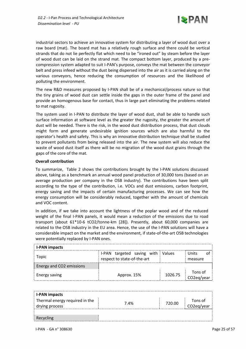
Overall contribution
To summarize, Table 2 shows the contributions brought by the I-PAN solutions discussed above, taking as a benchmark an annual wood panel production of 30,000 tons (based on an average production per company in the OSB industry). The contributions have been split according to the type of the contribution, i.e. VOCs and dust emissions, carbon footprint, energy saving and the impacts of certain manufacturing processes. We can see how the energy consumption will be considerably reduced, together with the amount of chemicals and VOC content.
In addition, if we take into account the lightness of the poplar wood and of the reduced weight of the final I-PAN panels, it would mean a reduction of the emissions due to road transport (about 61*10-6 tCO2/tonne-km [28]). Presently, about 60,000 companies are related to the OSB industry in the EU area. Hence, the use of the I-PAN solutions will have a considerable impact on the market and the environment, if state-of-the-art OSB technologies were potentially replaced by I-PAN ones.
I-PAN impacts
Topic I-PAN targeted saving with respect to state-of-the-art
Values Units of measure
Energy and CO2 emissions
Energy saving Approx. 15% 1026.75 Tons of
CO2eq/year
I-PAN impacts
Thermal energy required in the drying process
7.4% 720.00 Tons of
CO2eq/year
Recycling
D2.2 - I-Pan Process and Technological Architecture
Dissemination level - PU
I-PAN - GA n° 308630 Page 26 of 57
Recycled wood waste 50% 15000 tons/year
Chemicals
Resin content 5-10% 0.007 – 0.014
tons resin/tons
panels
Formaldehyde emissions Approx. 10% <~0.1 ppm
Others
Exhaust air 19% 104500 kg/h
Dust emissions 19% 83,79 kg/h
Curing temperatures Reduced by up to 10% < 100 °C
Wood saving due to 20% strand thickness reduction
30% 21000 tons/year
Table 3 I-PAN IMPACT: expected contributions with respect to emissions, CO2 footprint and energy saving. Values are based on an estimation of 30,000 tons of LSB panel production
D2.2 - I-Pan Process and Technological Architecture
Dissemination level - PU
I-PAN - GA n° 308630 Page 27 of 57
2 I-PAN PROCESSES AND TECHNOLOGIES
The I-PAN production process is articulated into various phases and work processes. The process hypothesized in I-PAN and its technological innovations may be divided as follows:
2.1 Log debarking area and recycled wood reclaim;
2.2 Green preparation area and strand production;
2.3 Strand storage green area;
2.4 Strand drying area + screening area;
2.5 Preparation, storage and dosing of the chemical components;
2.6 Core and surface layer blending area;
2.7 Forming and forming line area;
2.8 Press area;
2.9 After press area;
2.10 Forming line, press and after press dust extraction;
2.11 Spark detection and extinguishing system;
2.12 Explosion suppression system;
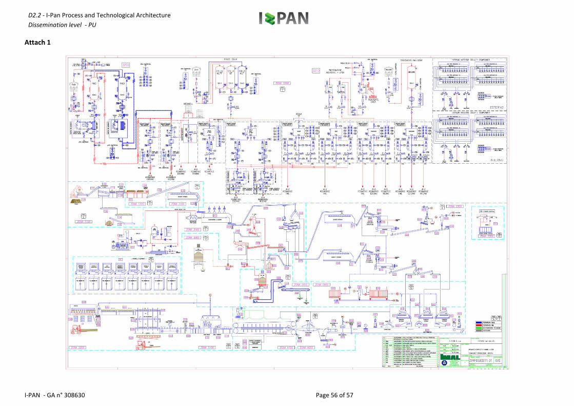
Attachment 1 shows the flow sheet for the project
2.1 LOG DEBARKING AREA AND RECYCLED WOOD RECLAIM
Purposes of the area:
To introduce the wooden logs into the production process (between 1800 mm and 2400 mm long);
Log debarking, bark separation
To recycle at least 50 % of the wood
Process
Both poplar logs and recycled wood with the following properties may be utilized in the production process:
Dimensions of logs: between 1800 mm and 2400 mm log
Minimum diameter of 80 mm and maximum which can fit inside a Ø 480 mm cylinder, 150 mm average with 12% max bark
Atro reference moisture content: 120% bark
Wood recycled from poplar waste or from suitably treated material
D2.2 - I-Pan Process and Technological Architecture
Dissemination level - PU
I-PAN - GA n° 308630 Page 28 of 57
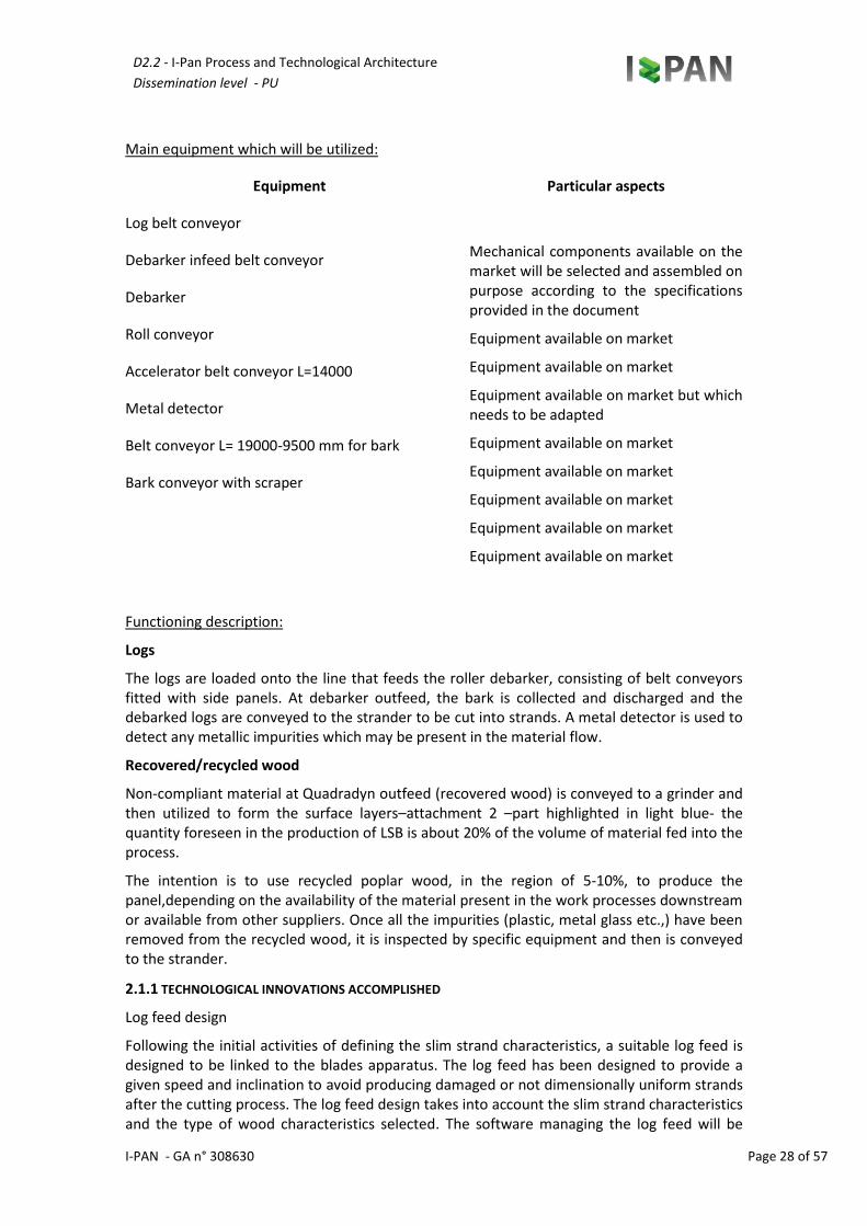
Main equipment which will be utilized:
Equipment Particular aspects
Log belt conveyor
Mechanical components available on the market will be selected and assembled on purpose according to the specifications provided in the document
Equipment available on market
Equipment available on market
Equipment available on market but which needs to be adapted
Equipment available on market
Equipment available on market
Equipment available on market
Equipment available on market
Equipment available on market
Debarker infeed belt conveyor
Debarker
Roll conveyor
Accelerator belt conveyor L=14000
Metal detector
Belt conveyor L= 19000-9500 mm for bark
Bark conveyor with scraper
Functioning description:
Logs
The logs are loaded onto the line that feeds the roller debarker, consisting of belt conveyors fitted with side panels. At debarker outfeed, the bark is collected and discharged and the debarked logs are conveyed to the strander to be cut into strands. A metal detector is used to detect any metallic impurities which may be present in the material flow.
Recovered/recycled wood
Non-compliant material at Quadradyn outfeed (recovered wood) is conveyed to a grinder and then utilized to form the surface layers–attachment 2 –part highlighted in light blue- the quantity foreseen in the production of LSB is about 20% of the volume of material fed into the process.
The intention is to use recycled poplar wood, in the region of 5-10%, to produce the panel,depending on the availability of the material present in the work processes downstream or available from other suppliers. Once all the impurities (plastic, metal glass etc.,) have been removed from the recycled wood, it is inspected by specific equipment and then is conveyed to the strander.
2.1.1 TECHNOLOGICAL INNOVATIONS ACCOMPLISHED
Log feed design
Following the initial activities of defining the slim strand characteristics, a suitable log feed is designed to be linked to the blades apparatus. The log feed has been designed to provide a given speed and inclination to avoid producing damaged or not dimensionally uniform strands after the cutting process. The log feed design takes into account the slim strand characteristics and the type of wood characteristics selected. The software managing the log feed will be
D2.2 - I-Pan Process and Technological Architecture
Dissemination level - PU
I-PAN - GA n° 308630 Page 29 of 57
integrated with an optical identification system able to provide a feedback to the flakers in order to obtain strands of a desired size and shape as well as managing the feeding speed. The equipment management software will operate in such a way that the pressure exerted on the log being cut, and the inclination of the knives vary so as to optimize energy consumption and strand quality. In addition, the software checks the size of the log to be cut, and optimizes the cut in such a way as to obtain strands of the same length.
IMAL is in charge of defining the technologies to be employed in the log feed apparatus, studying a system that utilizes less power for log feed and which can convey them at the highest possible speed.
D2.2 - I-Pan Process and Technological Architecture
Dissemination level - PU
I-PAN - GA n° 308630 Page 30 of 57
2.2 GREEN PREPARATION AREA AND STRAND PRODUCTION
Purpose
To produce strands approximately 0.3-0.5 mm thick, about 4-5 mm wide and 70-80 mm long
Equipment utilized:
Equipment Particular aspects
Strander Mechanical components available on the market will be selected and assembled on purpose according to the specifications provided in the document Equipment available on market but which is to be adapted to produce strands compliant with the target dimensions [, ] as defined above
Belt conveyor Mechanical components available on the market will be selected and assembled on purpose according to the specifications provided in the document Equipment available on the market
Functioning description:
At debarker outfeed, while the bark is collected and discharged, the debarked logs are conveyed to the strander to be cut into strands.
The Strander continuously produces strands of suitable dimensions and thickness by means of an advanced knife system suitable for processing the raw material travelling through.
The strands are produced by a known piece of equipment to which the following technical improvements have been applied:
knife angle of incidence modified to produce longer strands
knife depth incidence modified to reduce strand thickness
equipment control features modified to increase rotor advancement speed to minimize strand damage
researched market to find knives of elevated hardness to reduce maintenance and waste less raw material
2.2.1 TECHNOLOGICAL INNOVATIONS ACCOMPLISHED
Strand drying, handling and metering, in order to select and produce slim strands (80-100 mm long, 5-10 mm wide and 0.2-0.5 mm thick) with a low standard deviation and not damaged, with the aid of a vision & feedback system at several plant points . This includes the development and application of qualitative object description methods (QOD) that will permit interesting structures to be found in complex objects (e.g., an image, a large molecule, a biological regulation network, a time series) and relations as a multi-objective optimization problem;
IBL and the I-PAN partners took into consideration all the technical requirements of the overall production chain in order to achieve the desired objectives, while focussing on the aforementioned areas of interest. By the end of the Task, such requirements have been clearly defined and all subsequent research activities will be based on such initial assumptions and
D2.2 - I-Pan Process and Technological Architecture
Dissemination level - PU
I-PAN - GA n° 308630 Page 31 of 57
evaluations.
IBL defined the technical requirements, in collaboration with all the partners, that should be satisfied by the I-PAN technologies on the overall innovative manufacturing process. Moreover, IBL was able to provide IMAL and IDP with the specs of innovative features required for handling slim strands, including the expected characteristics of the special belt conveyors to be designed.
Definition of the blade characteristics
The characteristics of the rotors and blades have been analysed. The aim is to design a system, with a well given inclination of the blades and their properties, in order to save energy, produce minimal waste and at the same time cut strands accurately, i.e. 80-100 mm long, 5-10 mm wide and 0.2-0.5 mm thick. This is achieved by changing the inclination of the stainless steel blades, the speed at which the wood travels into the machine and the rotation speed of the rotor inside the flaker, responsible for strand production. IMAL was in charge of defining the technologies to be employed in the blades and rotors apparatus.
Handling, metering analysis and implementation
Thanks to IDP ‘s efforts, we are able to introduce innovative solutions, which will eliminate comb rolls for discharge by designing and developing special belt conveyors. The aim is to provide a system which does not damage the strands and which minimizes blade wear. The belt conveyor developed in this task will be specially designed for processing the characteristics of the slim strands obtained. The belt conveyor will be equipped with a control system for the handling, selection and storage of the strands for further processing (e.g. blending).
D2.2 - I-Pan Process and Technological Architecture
Dissemination level - PU
I-PAN - GA n° 308630 Page 32 of 57
2.3 STRAND STORAGE GREEN AREA
Purpose:
Storage and metering of strands for continuous feed to the dryer
Equipment utilized:
Dryer feed bin Mechanical components available on the market will be selected and assembled on purpose according to the specifications provided in the document Equipment available on the market
Functioning description:
The strands are metered continuously to the dryer. Two infrared moisture measuring systems, one at infeed and the other at outfeed, monitor strand moisture content continuously.
The bin, with a storage volume of 200 m³, acts as a storage silo and reserve for the strands and at the same time is able to meter the process material continuously and accurately thanks to a conveying system which does not ruin the strands and limits the generation of fine material.
The bin filling level provides the feedback to the next zone to determine the required instant flow rate.
The maximum (mechanical) level sensor stops bin load and signals a functioning anomaly to the system.
A system to optimize bin discharge is currently being investigated to ensure an homogenous and constant dryer belt load.
D2.2 - I-Pan Process and Technological Architecture
Dissemination level - PU
I-PAN - GA n° 308630 Page 33 of 57
2.4 STRAND DRYING AND SCREENING AREA
Purposes:
to dry the strands (evaporating at least 57% of the moisture content);
to screen the strands out into 3 fractions on the basis of their dimensions
Main equipment utilized:
Equipment Particular aspects
Belt dryer Equipment available on the market but which is to be adapted to overcome strand issues
Equipment available on the market
Equipment available on the market
Equipment available on the market
Equipment available on the market
Mechanical components available on the market will be selected and assembled on purpose according to the specifications provided in the document
Boiler to produce hot water
Various conveyors
Roller screens
Strand distribution system
Functioning description:
The product travels through the belt dryer chamber through which hot air flows and about 57% of its initial moisture content is evaporated.
The belt dryer, manufactured by STELA and adapted to suit the technical requirements of the IPAN process, is to possess the following technical characteristics:
Capacity (H2O evaporated)
12 ton/h
Capacity (dried strands) 9.6 ton/h
Initial moisture content 60% Atro
Final moisture content 3% Atro (+- 0.5%).
Mat height 70 ÷ 200 mm Working temperature 90 °C
Water temperature at inlet
95÷105 °C
Water temperature at outlet
70÷80 °C
Thermal power Approx. 13.5 MWt 16.2 MWt at -10°C
Installed power 332 KWe
Power savings with respect to similar models
-10% Strand not ruined About 90% of the flow at infeed
D2.2 - I-Pan Process and Technological Architecture
Dissemination level - PU
I-PAN - GA n° 308630 Page 34 of 57
from calculations
The hot water boiler is a commercial energy-efficient boiler with low environmental emission and has the following features:
Working thermal power 6 MW/h Heat input 6.522 MW/h
Useful output at lowest load 92.5% Fume flow rate to power ratings 13450 m³/h
Average output 92% Dust emission 1 mg/m³
NOx emission like NO2 70 mg/m³ CO Emission 50 mg/m³
SO2 Emission 20 mg/m³
(*) all values are given with an oxygen content in the gaseous effluent at a project rated 3%.
The heat exchanger is a commercial 3 MW tube bundle heater, with a thermal oil primary circuit and a secondary hot water circuit at project temperature (110 °C at 6 Bar).
Drying efficiency is continuously monitored by an on-line system located at material outfeed, after the discharge screw conveyor.
The strands then move on to the roller screening phase where they are screened out into 3 fractions on the basis of their dimensions (fine/core, core, face) and four fractions in relation to their geometrical shape:
A. Fine material ………….. (estimated as being about 15-30% of the total);
B. Extra fine material ………….. (estimated as being about 30-40% of the total);
C. Core layer material … (estimated as being about 40-60% of the total);
D. Face layer material ... (estimated as being about 40-60% of the total);
An optical controlling system (UNIMI/ECS) has been foreseen in this area due to the necessity to ensure that the strands remain intact, to highlight any breakage in the dried strands.
2.4.1 TECHNOLOGICAL INNOVATIONS ACCOMPLISHED
The reduction in the drying process costs is the object of the research and will be achieved through an efficient low-caloric heat drying.
Several measurements will be conducted to monitor and obtain accurate information on the air system temperatures in all its parts, exhaust air in particular. Such information will be important for estimating future systems running at their full potential.
The hot air is generated in indirect heat exchangers supplied with hot water at about 105 °C, and fans ventilate the strands. Such fans are arranged in order to optimize convection and to enhance the drying process. The product is shifted and mixed after half the drier length by means of a proven turning device in order to achieve a dried product as homogeneous as possible.
D2.2 - I-Pan Process and Technological Architecture
Dissemination level - PU
I-PAN - GA n° 308630 Page 35 of 57
We have also studied a controlling and monitoring system that acts during the manufacturing process, since it is essential to guarantee drying efficiency and, more indirectly, energy consumption. The return flow temperature and the hot air temperature is measured and according to this data, fan speed was regulated solely to achieve the best drying performance.
Energy saving achieved during this manufacturing step compared to a standard drying system.
STELA has conducted a research on the cost reduction for the innovative drying system for low density products in order to reduce dust emission and power consumption per kg of material handled, such an application will be implemented within the IPAN project.
A novel design and technological solutions have been studied to substantially reduce manufacturing times and the presence of the VOC substances released into the environment.
Hot air generated and fans ventilating the strands.
The fact the new system has an optimized design to enhance convection efficiency and the use of exhaust air for different cycles. In order to avoid the high dust emissions and to save energy, the exhaust air has been re-circulated with special heat-exchangers up to 95 °C to provide the most suitable drying air conditions for water evaporation.
Re-circulating the air has accelerated the drying process making it more efficient than state-of-the-art systems. More specifically the drying system control has a flexible control range retention time in active zones of 6 - 30 min.
The dust content was filtered from the product layer and the belt themselves, so that less wooden dust is released into the air. Moreover the drying system is run at low pressure to further reduce the amount of VOCs released into the environment. The velocity of the air through the belt is very low so that the filter (plastic belt and the product layer on it) work correctly.
STELA has carried out research on the times and reduction in VOCs for the innovative drying system for low density products in order to reduce dust emission and power consumption per kg of handled material.
2.4.2 REFINING AREA AND FINE LAYER BLENDING
Purposes:
Refining fraction 2 particles (oversize)
Dosing and blending of fine material (dust for surface layers)
Main equipment utilized:
Equipment Particular aspects
Refiner mill Equipment available on market
Equipment available on market
Equipment available on market
Equipment available on market
Equipment available on market
Equipment available on market but adapted to
Refiner mill suction line
Double metering screw and bin
PAL 160 CTS blender
4 screw doser, 250 spiral
D2.2 - I-Pan Process and Technological Architecture
Dissemination level - PU
I-PAN - GA n° 308630 Page 36 of 57
Conveying systems prevent strand breakage
Mechanical components available on the market will be selected and assembled on purpose according to the specifications provided in the document
Functioning description:
The oversize material-fine reject material, screened out by the roller screen is sent to the mill for further refining and then screened by the mesh screen to screen out dust, fine material for the surface layer, core layer material.
The screen selects the dry material on the basis of the project specified dimensions.
After the screening process, the fine material for the surface layers is conveyed to the dosing system (WEIGHING AND DOSING) and blending system to feed the fine layer formers.
Self-cleaning disk chain conveyor at blender outfeed
The pneumatic dust extraction conveyor from the refiner mill consists of piping, fan and cyclone with rotary valve.
D2.2 - I-Pan Process and Technological Architecture
Dissemination level - PU
I-PAN - GA n° 308630 Page 37 of 57
2.5 STORAGE, PREPARATION AND DOSING OF THE CHEMICAL COMPONENTS
Purposes:
Resin transfer [MDI, MUPF , MUF, UF] from tank or truck
Hardener and urea preparation and transfer
Emulsion transfer from tank and truck
PMDI /Mesamol core and face layer dosing
Fine/core and face layer resin dosing
Water and urea dosing for fine, core and face layers
Hardener dosing for fine, core and face layers
Emulsion dosing for fine, core and face layers
Main equipment utilized:
Chemical component transfer systems Equipment available on the market
Equipment available on market but adapted to prevent strand breakage
Mechanical components available on the market will be selected and assembled on purpose according to the specifications provided in the document
Dosing systems
Functioning description:
A motorized pump transfers the liquid from the truck to the storage tank for each type of chemical component (resin, emulsion, PMDI).
Each storage tank is equipped with a double level control to prevent the occurrence of environmental accidents:
- Pressure level control to continuously monitor tank level;
- Vibrating level control for when maximum level is reached.
Each tank has a motorized pump to transfer the liquid from the tank to the dosing box. The water dosing box on the other hand is connected to the main supply line and is equipped with a solenoid valve which opens to let water into the box when a request is made.
Each dosing box is equipped with a volumetric flow meter to ensure the component is dosed correctly in relation to the instant quantity of wood within the process.
The dosed chemical components are then conveyed to an injection chute at blender infeed to be blended with the wood.
The PMDI is sent to the face and core blenders by a pre-assembled dosing unit equipped with a pump for high pressure injection.
The adhesive is sent to the fines blender or, suitably mixed inside a static mixer where it is finely homogenized, to the high pressure injection system at the infeed to the face and core blenders.
D2.2 - I-Pan Process and Technological Architecture
Dissemination level - PU
I-PAN - GA n° 308630 Page 38 of 57
Hardener and emulsion are sent separately to the face, core and fines blender by a dosing unit equipped with pump for high pressure injection.
D2.2 - I-Pan Process and Technological Architecture
Dissemination level - PU
I-PAN - GA n° 308630 Page 39 of 57
Water and urea are sent separately to the face, core and fines blender by a dosing unit equipped with pump for low pressure injection.
The resin and chemical component injection system consists of two injection beams for each face and core blender, each beam consisting of a set of separate injection nozzles with 3 manifolds fed with:
Resin-hardener or PMDI
emulsion
water-urea
Raw materials: Resin, chemical components, water as per the project specifications
Resin Liquid resin compliant with European standard quality.
MUPF Approximate concentration: 64%
MUF/UF Approximate concentration: 64%
PMDI Approximate concentration: 100%
Paraffin
Emulsion Approximate concentration: 50-58%
Hardener: suitable for MUPF / UF resin
Consumptions (tolerance: +5%):
OSB/3
Component Face Core
MUF/UF (dry to dry wood) 9.6%
PMDI (dry to dry wood) 3.9% 3.9%
Paraffin (dry to dry wood) 2% 2%
D2.2 - I-Pan Process and Technological Architecture
Dissemination level - PU
I-PAN - GA n° 308630 Page 40 of 57
LSB
Component Face Middle Core
MUF/UF (dry to dry wood) 12% 9.6% 9.6%
PMDI (dry to dry wood) 3.9% 3.9%
To be verified in the work process
Paraffin (dry to dry wood) 1% 1% 1%
Hardener (dry to dry wood) 3.5%
WATER
pressure 5 bar min. temperature < 35°C
Hardness < 120 mg CaO/l Chloride content < 80 ppm
pH a 20°C 6 ÷ 7.5 Maximum consumption for face layer, intermediate layer and core layer dosing
1200 kg/h
2.5.1 TECHNOLOGICAL INNOVATIONS ACCOMPLISHED
The polymerization of the urea based resins guarantees a higher moisture content in strands and low curing temperatures.
We have considered all the technical requirements of the overall production chain in order to achieve the desired objectives.
IBL has defined, in collaboration with all the partners, the technical requirements that have to be met by the I-PAN technologies on the overall innovative manufacturing process. CTECH has supported IBL in the definition of the overall process architectural approach. IMAL, STELA, IDP, ECSC, UMIL have been asked to provide technical specifications of the technologies for the development of the project .
CHI will carry out a prior state of the art search using web databases of patents and publications to trace and study any related work in the area of resins for OSB and resins for bonding recycled/poplar wood using a sample sent by IBL/IMAL.
CHIMAR will design, on the basis of the samples sent in December and information received and processed on the patents, a resin which meets the project requirements.
IMAL has extended the prototype application of the new resination system to the LSB board with the aim to improve blending quality, performance and to reduce resin consumption and
D2.2 - I-Pan Process and Technological Architecture
Dissemination level - PU
I-PAN - GA n° 308630 Page 41 of 57
consequently the impact on the environment.
The development of the resin precursors and polymerization based on urea, formaldehyde, melamine and/or phenol will be prepared in the lab and then the plant.
The synthesis of thermosetting formaldehyde-based resin samples and all experimental resins in the laboratory is characterized according to standard analytical methods (solids content, viscosity, pH value, specific gravity, free formaldehyde, reactivity (gel-time, stability) and the reactivity/curing behaviour of the experimental resins is determined by performing DSC or similar analysis tests.
The resin samples are prepared for an initial application in the production of laboratory strand boards and at the premises of CHI. Suitable additives such as hardeners/cross-linking agents, formaldehyde catchers, wax emulsions, will be used to formulate the glue mixture for the coating/spraying of the strands.
The physical, mechanical and formaldehyde emission properties of the panels produced will be determined following the requirements of European standard EN 300 for OSB type panels. The evaluation results will help to draw useful conclusions for the performance of the experimental resins and their effectiveness as satisfactory binders for LSB.
IMAL will contribute to the resin validation activities.
D2.2 - I-Pan Process and Technological Architecture
Dissemination level - PU
I-PAN - GA n° 308630 Page 42 of 57
2.6 CORE AND SURFACE LAYER BLENDING AREA
Purposes:
storage and continuous dosing of the strands to the blenders without breaking up their 3-dimensional composition
continuous weighing and dosing of the strands
strand resination
conveying of the resinated strands to the formers
Main equipment utilized:
Equipment Particular aspects
Bins Mechanical components available on the market will be selected and assembled on purpose according to the specifications provided in the document Equipment available on the market
Equipment available on the market but requiring modification to prevent strand break up
Equipment available on the market but requiring modification
Conveyors
Chute with accelerator rolls for strands
Functioning equipment:
The bins act as storage silos for the strands for the core and surface layers respectively. The strands are metered continuously and accurately to the bin scales by means of an innovative 4-chain conveyor which prevents strand break up and at the same time limits the generation of fine material.
At bin outfeed the belt conveyors feed the material to the bin scales in a continuous and controlled manner which then weigh the core/face material to enable the correct calculation of the quantity of resin and additives required for the subsequent blending process.
A system to monitor moisture content is installed at the outfeed to the weighing bins which provides instant information.
The material that has been weighed and metered by the weighing bin falls into an acceleration chute equipped with two counter-rotating brush rolls which give the material the right amount of acceleration to optimize the subsequent resin/additive injection process.
The resin is applied at high pressure by two rows of special nozzles fed by the chemical component dosing system to ensure that it is distributed in a uniform manner.
The process material now containing the right amount of bonding agent is fed into the blenders where it is blended mechanically and in a controlled manner such as not to break the strands.
A belt conveyor system at blender outfeed conveys the resinated material from the blenders to the formers for the next stage of the work process.
2.6.1 TECHNOLOGICAL INNOVATIONS ACCOMPLISHED
The innovation to the blending process is the introduction of novel nozzles and blender technologies, ranging from image processing to interoperability. The IMAL research activities are focussed on the nozzles, aimed at optimizing the distribution of the resin over the mat
D2.2 - I-Pan Process and Technological Architecture
Dissemination level - PU
I-PAN - GA n° 308630 Page 43 of 57
layers. Current state-of-the-art technology simply distributes a relatively uncontrolled amount of resin over the dried strands. The I-PAN innovation consists in distributing uniform films of resin over the strands. This has led to the development of a carefully designed and engineered nozzle.
The innovation lies in the definition of specific illumination systems, innovative image processing algorithms, and classification algorithms, which are also based on computational intelligence. In particular, the real-time evaluation of the strand characteristics and classification according to granulation, orientation and size is addressed via sophisticated algorithms. Images will be processed via a Filtered Image Analysis (FIA) and Fast Fourier Transform (FFT) or similar methods. The 2D images obtained, coupled with 3D models, will thus provide estimates of macro-pores, void regions, their distributions and morphologies. Such information will be used to coordinate machine operation, optimize the handling and monitoring processes, and provide a better quality control.
IBL, IMAL and UNIMI will organize the interoperability between the equipment and the optical feedback.
The focus on the blending machine innovation and the integration of vision-based monitoring with the blender for overall online blending control has been innovated with the introduction of novel nozzles and blending technology, ranging from image processing to interoperability.
In fact, the quantity of resin is related to the size of the strands. The monitoring system can also reduce possible strand damage due to long blending time. Real-time monitoring will control the blending effects on the strands and the resin amount by advanced vision and three-dimensional reconstruction techniques to monitor the strands after the resin has been sprayed as well. Open blenders consent the monitoring of the strands as they fall from the conveyor belts. Cameras suitably positioned in several locations will permit the analysis of the strand’s surface by image processing: three-dimensional reconstruction will be used to analyze surface roughness and strand thickness for better controlling the amount of resin sprayed, preventing possible strand damage and, in turn, a better utilization of resources and raw materials to obtain lighter and less expensive panels.
D2.2 - I-Pan Process and Technological Architecture
Dissemination level - PU
I-PAN - GA n° 308630 Page 44 of 57
2.7 FORMING AREA AND FORMING LINE
Purposes:
Formation of the OSB mat into 5 layers
Continuous metal detection
Side trimming of mat and elimination of off-cuts
To inject steam into the mat prior to pressing
Control of mat density profile and weight
Reject of non-conforming mats before they go into the press
Main equipment utilized:
Equipment Particular aspects
Core/face forming bin
Mechanical components available on the market will be selected and assembled on purpose according to the specifications provided in the document Equipment available on the market
Equipment available on the market
Equipment available on the market
Equipment available on the market which needs to be adspted
Equipment available on the market but adapted to project
Equipment available on the market
Equipment available on the market
Equipment available on the market
Equipment available on the market
Equipment available on the market
Equipment available on the market
Traversing screw
Face forming head 2
Bottom/top face layer dust former
Steam injection unit
Forming line + press feed line
Mat weighing scale H=1400 L=3050x1350
PULSAJET release agent dosing on press
Pinch rolls to prepare mat
Double side trimmer saw
Metal detector
D2.2 - I-Pan Process and Technological Architecture
Dissemination level - PU
I-PAN - GA n° 308630 Page 45 of 57
Functioning description:
The traversing screw conveyors load the forming bins in a uniform manner over their entire width.
Each bin has an internal volume of approximately 5 m³ and feeds a forming head with material suitable for either the core or face layer: the strands are appropriately oriented and distributed to form a 2600 mm wide mat on the forming belt. The face layer forming heads lay the strands longitudinally while the core layer forming head lays the strands transversally.
The fine formers on the other hand, lay the outer layers of dust. The core layer, laid directly on the forming belt is pre-compressed as it travels under the pressure rolls, the height of which may be adjusted.
A steam injection unit positioned immediately after the forming station applies steam to the outer surface of the mat (500 kg/hour of steam max).
The sides of the mat are trimmed by the double longitudinal saw prior to pressing to achieve a width of between 1960 mm and 2600 mm:
The longitudinal saw consists of a metal load bearing frame which supports two cutting units each housing an independently moving motorized blade and relative suction hoods.
The trimmings are collected on a transversal screw conveyor mounted below and conveyed to a recycling circuit.
Two rotating brushes keep the blades clean as they rotate, conveying dust and trimmings to the collector screw below.
Once the sides of the mat have been trimmed, the mat is weighed on a weighing scale and x-rayed to take the surface density profile. Any metals or foreign contaminants which may be present in the board are detected as it passes underneath a metal detector .
The mat is rejected if any defects or foreign contaminants are found through a reject device which opens and discards mats which are not suitable for the pressing process. The rejects are conveyed pneumatically to a storage bin to be recycled back into the work process.
The mat then proceeds and enters the DYNASTEAMPRESS press, which has the particular characteristic of starting the pressing process with the injection of saturated steam into the top and bottom of the mat to then proceed with the traditional pressing and curing processes.
In cases where PMDI is used as the bonding agent for the surface layer, a release agent is sprayed onto the steel press belts.
2.7.1 TECHNOLOGICAL INNOVATIONS ACCOMPLISHED
IBL has defined, in collaboration with all the partners, the technical requirements that should be met by the I-PAN technologies on the overall innovative manufacturing process.
A suitable 0.2-0.5 mm thick layer has been studied to apply to the mat surface. Wood dust needs to be produced in the mills and then screened out to obtain the proper size. Resin is then applied to the dust and the mix is placed continuously over the top and bottom of the mat to obtain a uniform surface. Moreover, the application of such a layer means that the surface of the mat may be laminated with various coatings.
The study of the algorithms for the software dedicated to monitor and control mat formation, with particular attention to strand orientation are extremely important to reach this aim. The main objective is to ensure a suitable orientation of the flakes in each strand to achieve the
D2.2 - I-Pan Process and Technological Architecture
Dissemination level - PU
I-PAN - GA n° 308630 Page 46 of 57
desired panel properties. Advanced vision systems, based on multiple views and three-dimensional surface reconstruction, and dedicated illumination systems are designed for high accuracy and precise measurements of the strand shape (for layer composition) and orientation (for optimum strand distribution). The vision system evaluates the shape of the particles as they fall, avoiding blockage, by using three-dimensional surface reconstruction from multiple views; structured light patterns deal with the lack of reference background and the image acquisition in a single instant or at ultra-high frame rate. The vision system, based on three-dimensional surface reconstruction, also monitors strand distribution and orientation on the conveyor belt to properly compose the mat using multiple view systems with cameras on the top of the belt, projected static patterns for instantaneous acquisition, and structured-light techniques. Heavy duty and adaptive techniques, including computational intelligence, have been developed.
High computational demand dictates a choice of suitable hardware and software architectures for real-time operation.
Proper techniques for surface treatment have been developed and implemented and in particular, the technological innovation is in the application of a layer of wood dust over raw LSB boards. Since such boards could have a relatively rough and inhomogeneous surface, and certain strands could be lying in an unwanted orientation or direction, the resinated wood dust will cover the empty surface spaces. Furthermore, an innovative pre-compression system has been studied, so that the mat may be conveyed between the conveyor belt and press infeed without the dust being dispersed into the air.
2.8 PRESS AREA
Purpose: to press and cure the wooden mat continuously, reducing power consumption by 7.4%.
Equipment:
Main equipment utilized :
Equipment Particular aspects
DYNASTEAMPRESS 15000x2600 OSB 400 m³/day
Technical details:
Size of hot platen :2600 x 15000 mm
Installed power : 256.4 kW
Hydraulic pressure: 310 bar, thermal oil circuit consisting of a pumping system to circulate the oil for heating the press
Oil temperature :250 °C
Installed power :232 kW
Modified equipment not available on the market Mechanical components available on the market will be selected and assembled on purpose according to the specifications provided in the document
Functioning description:
The press operates with hot plates and the material is conveyed on special belts which transfer the pressure and heat through the mat to polymerize the adhesive agent inside the mat.
D2.2 - I-Pan Process and Technological Architecture
Dissemination level - PU
I-PAN - GA n° 308630 Page 47 of 57
2.8.1 TECHNOLOGICAL INNOVATIONS ACCOMPLISHED
The press supplied by IMAL will be redesigned to achieve the characteristics of the project board, improving performance with respect to similar equipment currently available, by placing a mat steam injection unit upstream and downstream, after adapting it to produce the desired board properties, to achieve a better productive quality. Before the top fine layer is laid on the mat, the first steam injection unit “irons” the mat to flatten out its surface roughness, while the steam injection unit placed prior to the press is used, after suitable modification, to augment mat conductivity and hence reduce power consumption per unit of pressed product.
2.8.2 LONGITUDINAL AND TRANSVERSAL SAW LINE
Purposes:
Longitudinal cut at press outfeed
Transversal cut at press outfeed
Main equipment utilized:
Equipment Particular aspects
Roller conveyor at press outfeed Mechanical components available on the market will be selected and assembled on purpose according to the specifications provided in the document Equipment available on the market
Equipment available on the market
Continuous longitudinal/transversal saw
Functioning description:
The longitudinal saw trims the wooden board continuously to obtain the pre-defined width.
A board sample may be taken periodically to identify problems of various nature within the process, which can slowly and progressively cause the product to deviate from the required production standards.
The saw has a sample cutting function to carry out this sampling control where the sample may be collected from a special box and then analysed in the laboratory.
The saw will be designed so that the cutting speed is synchronized with the speed the mat travels at.
D2.2 - I-Pan Process and Technological Architecture
Dissemination level - PU
I-PAN - GA n° 308630 Page 48 of 57
2.9 AFTER PRESS LINE
Purposes:
panel quality control at press outfeed: thickness, no internal defects (blisters), weight
Reject of defective boards or those which do not conform to the production parameters
Internal bond, bending strength, absorption, thickness, density
Cooling, pack forming and unloading of compliant boards
Main equipment utilized:
Equipment Particular aspects
Star cooler Mechanical components available on the market will be selected and assembled on purpose according to the specifications provided in the document Equipment available on market
Equipment available on market
Equipment available on market
Stacking system
Blistered board detector
Functioning description:
Once the board has been cut, it undergoes the next non-destructive quality controls (blistered board detector, 5-point thickness measuring gauge, weight measurement).
The board is rejected if a defect is found in which case it is sent to the reject station.
Boards that meet the production parameter requirements are conveyed to the star cooler, after which they are cut down the centre and stacked in packs on the elevator table. The boards produced in such a manner are then sanded on a dedicated sanding line.
Detection of blistered boards
The on-line blistered board detector manufactured by IMAL will be redesigned to adapt it to the property requirements of the LSB board.
D2.2 - I-Pan Process and Technological Architecture
Dissemination level - PU
I-PAN - GA n° 308630 Page 49 of 57
2.10 FORMING LINE, PRESS AND AFTER PRESS DUST EXTRACTION
Purposes:
Dust extraction from the emission points in various areas of the plant;
Filtration of air before it is released into the atmosphere;
Main equipment utilized:
Equipment Particular aspects
Suction lines Equipment available on the market
Equipment available on the market
Mechanical components available on the market will be selected and assembled on purpose according to the specifications provided in the document
Conveying lines
Functioning description:
All the process equipment requiring dust extraction is connected to the suction plant so that the filters located at various points of the plant extract all the dust from the machinery operating in the various areas of the plant. Innovative solutions have been adopted to minimize dust emission into the environment inside and outside of the building.
D2.2 - I-Pan Process and Technological Architecture
Dissemination level - PU
I-PAN - GA n° 308630 Page 50 of 57
2.11 SPARK DETECTION AND EXTINGUISHING AREA
Purposes:
Detection and extinguishing of sparks
Construction of a flooding system for equipment with fire/explosion risks;
Main equipment utilized:
Equipment Particular aspects
Spark detecting system Equipment available on the market
Equipment available on the market
Mechanical components available on the market will be selected and assembled on purpose according to the specifications provided in the document
Flooding and explosion relief system
Functioning description:
A manually activated system floods equipment that has an intrinsic fire risk (only the alarm is automatic) and where it is not possible to extinguish the flames from the outside.
Extinguishing linked to a spark detecting system on the other hand is entirely automatic (installed for each piece of equipment where such a risk is present) and the extinguishing points are equipped with automatic solenoid valves.
D2.2 - I-Pan Process and Technological Architecture
Dissemination level - PU
I-PAN - GA n° 308630 Page 51 of 57
2.12 EXPLOSION RELIEF SYSTEMS
Purpose: to mitigate the effects of an explosion;
Main equipment utilized:
Equipment Particular aspects
Explosion relief system Equipment available on the market
Mechanical components available on the market will be selected and assembled on purpose according to the specifications provided in the document
Functioning description:
The plant has been designed to minimize the risk of explosion. However, due to the intrinsic nature of the material handled, it is not possible to fully eliminate this risk. An accurate analysis of the plant has consequently been carried out, to assess the equipment where there is risk of explosion and to equip the machinery with pre-determined explosion relief rupture panels to attenuate the pressure of the explosion. The plant will therefore need to be equipped with an explosion detection system and with chemical suppressors that are able to partition off the explosion to prevent a domino effect within the plant.
The press is to be equipped with its own fire suppression system to ensure the necessary safety if a fire should break out in the equipment.
The optimal system should consist of water sprinklers activated by optical flame warning devices.
The flame warning devices are equipped with an electronic optical control and transmit an anomaly to the signalling and fire extinguishing station.
Furthermore, the extinguishing plant may be activated manually in the immediate vicinity of the press and in the control area.
The sprinklers are positioned above and inside the press to ensure a safe coverage of the areas at risk and minimize water consumption.
The sprinklers operate at a working pressure of between 4 and 10 bar so that the water is sprayed in drops of a size such as to optimize the extinguishing of the flame.
D2.2 - I-Pan Process and Technological Architecture
Dissemination level - PU
I-PAN - GA n° 308630 Page 52 of 57
3 CONCLUSIONS
The I-PAN project, in all its phases, requires its partners to focus on technological innovation and improvement of the processes affecting the environment to reduce resource consumption and environmental emissions (both within the work area and into the atmosphere) aimed at reducing the quantity of resin employed, working the press at lower temperatures with respect to similar systems and a series of technical innovations scattered throughout the project, the combination of which will achieve the project target.
In Task 2.2, as reported in the present deliverable, the processes and related architectures have been analysed and designed in terms of requirements and innovation according to the project objectives. In particular the I-PAN partners address the following areas:
Log debarking area and recycled wood reclaim: the wooden logs (between 1800 mm and 2400 mm long), are fed into the production process after which they go through the debarking process, enabling at least 50% of the wood to be recycled. A metal detector detects any metallic impurities which may be present.
Green preparation area and strand production: the strands produced are approximately 0.3-0.5 mm thick, 4-5 mm wide and 70-80 mm long. A strander produces strands of suitable dimensions and thickness continuously utilizing an advanced system of knives that have been adapted to the type of raw material employed in the work process. An optical control system continuously and statistically monitors the dimensions and dimensional characteristics of the strands.
Strand storage green area, where the strands are stored and metered for continuous feed to the dryer. Two infrared measuring systems, one at dryer infeed and the other at dryer outfeed continuously monitor strand moisture content. The maximum level sensor (mechanical) stops material load and signals a functioning anomaly to the plant.
Strand drying and screening area, where the strands are dried (losing at least 57% of their moisture) and then separated into 3 fractions on the basis of their dimensions. Dryer efficiency is constantly monitored by an on-line system located at material outfeed, after the discharge screw conveyor. The optical system continuously and statistically monitors the dimensions and dimensional characteristics of the strands during this phase
Preparation, storage and dosing of the chemical components, where the resins are transferred [MDI, MUPF, MUF, UF] , hardener, urea and emulsion are prepared and transferred, after which they are dosed. The resin and chemical component injection system consists of two injection wings for each core and face layer blender; each wing is equipped with a set of separate injection nozzles with 3 manifolds supplied with: i) resin-hardener or PMDI; ii) emulsion; iii) water-urea.
Core and surface layer blending, which consists in the storage and continuous metering of the strands to the blenders, maintaining their three-dimensional composition throughout the weighing operation, blending process and conveying of the resinated strands to the formers. A system controls the moisture content of the material at the outfeed to the weighing bins, after which the material is weighed and metered and then the resin is sprayed uniformly at high pressure over the strands by two sets of special sprayer nozzles fed by the chemical component dosing system.
Forming and forming line area where the OSB /LSB mat is formed into 5 layers and at the same time, is checked for the presence of metals, the sides are trimmed, it is controlled for quality and then steam is injected prior to its entry into the press. A steam injection unit injects steam into the upper surface of the mat (max 500 kg/hour
D2.2 - I-Pan Process and Technological Architecture
Dissemination level - PU
I-PAN - GA n° 308630 Page 53 of 57
of steam). The optical system continuously and statistically monitors the dimensions and dimensional characteristics of the strands
Press area, where the wooden mat is pressed and cured continuously. The press supplied by IMAL has been designed to achieve the required panel properties and where performance is improved with the installation of a Steam injection unit, adapted to the characteristics of the board in the production process.
After press area, where board quality is controlled at press outfeed in terms of thickness, internal flaws (bubbles) and weight. The boards are cooled, cut down the centre and stacked into packs on the elevator table. The boards are then conveyed to the next stage of the production process to be sanded on a dedicated line. The board then undergoes non-destructive quality control testing (blister detection, 5-point thickness measurement, weighing).
Forming line, press and after press dust extraction, where the process equipment is connected to the suction plant such that the filters situated at various locations extract all the dust from the equipment operating in the various areas of the plant.
Spark detection and extinguishing, where a manually activated system is installed to flood equipment with an intrinsic risk of explosion.
Explosion suppression: the plant has been designed to minimize the risk of explosion and is equipped with chemical suppressors that are able to partition off the explosion to prevent the domino effect from occurring.
Introduction of algorithms, linked to the optical control systems for some of the most critical stages of the process (quality, dimensions and strand break up, strand orientation when arranging the mat or in the blending phase), reduce operator intervention and supply further details on how the process is progressing to improve quality and reduce the impact on the eco-system. The introduction of new resination techniques (high pressure blending, based on past experience but with the relative technological adaptations) or for the pressing phase (introduction of two innovative units (Dynasteam) downstream of the press will render the plant a European showcase for the technology applied.
Recycling: the application within the production process of parts of poplar formerly treated as a by-product and used as fuel or worse still sent to the dump, will help reduce the process’s carbon footprint, optimizing the production process and mitigating the impact on the environment.
The novelties : all the partners will benefit from the innovation effort so that such an innovation may be extended throughout the panel world.
D2.2 - I-Pan Process and Technological Architecture
Dissemination level - PU
I-PAN - GA n° 308630 Page 54 of 57
4 BIBLIOGRAPHY
1. EPF – European Panel Federation.
2. CEI-bois, residues Wood and wood-based panel products: sustainable and renewable.
3. Status of Energy Use in the Canadian Wood Products Sector. s.l. : Canadian Industry Program for Energy Conservation (CIPEC), 2009.
4. DOE Poplar Genome Based Research for Carbon Sequestration in Terrestrial Ecosystems.
5. Tuskan, G. Genome-Enabled Discovery of Carbon Sequestration Genes in Poplar project.
6. European forests provide solutions to future challenges. s.l. : Copa and Cogeca, 2011.
7. G.E. Scarascia-Mugnozza, Marcel R. Hoosbeek. Increased litter build up and soil organic matter stabilization in a poplar plantation after 6 years of atmospheric CO2 enrichment (FACE): Final results of POP-EuroFACE compared to other forest FACE experiments. 2008.
8. Woody biomass production during the second rotation of a bio-energy Populus plantation increases in a future high CO2 world. C. Calfapietra, M. Liberloo. 2006.
9. The Effect of Elevated Atmospheric CO2 Concentration on Two Populus Clones Grown in a FACE System. R. Tognetti, A. Raschi. 2005.
10. H. Thoemen, M. Irle, M. Sernek. Wood-Based Panels: An Introduction for Specialists, Brunel University Press. 2010.
11. T. Nishimura, J. Amin, M. P. Ansell. Image analysis and bending properties of model OSB panels as a function of strand distribution, shape and size. s.l. : Wood Science and Technology, Springer Berlin/Heidelberg, vol. 38, pp. 297-309, 2004.
12. Influence of log temperature in irregularities on strand geometry detected by digital image analysis. V. Gaete-Martinez, S.M.Shaler. s.l. : Maderas. Ciencia y tecnología, vol. 9, pp. 211-221, 2007.
13. Virtual environment for granulometry analysis. S. Ferrari, V. Piuri, F. Scotti. s.l. : Proc. IEEE Conference on Virtual Environments, Human-Computer Interfaces and Measurement Systems, pp. 156-161, 2008, 2008.
14. Image processing for granulometry analysis via neural networks. S. Ferrari, V. Piuri, F. Scotti. 2008 : Proc. IEEE International Conference .
15. The relationship between the arrangement of wood strands at the surface of OSB and the modulus of rupture determined by image analysis. T. Nishimura, M.P. Ansell, N. Ando. s.l. : Wood Science and Technology, Springer Berlin/Heidelberg, vol. 35, pp. 555-562, 2008.
16. C. Hu, C.I. Tanaka, R. Okai, T. Ohtani. C. Hu, C.I. Tanaka, R. Okai, T. Ohtani. s.l. : Annals of Forest Science, pp. 385-390, 2005.
17. Monitoring fiber orientation in OSB during production using filtered image analysis. T. Nishimura, M.P. Ansell. s.l. : Wood Science and Technology, Springer Berlin / Heidelberg, vol. 36, no. 3, pp. 299-309, 2002.
18. Fast Fourier Transform and Filtered Image Analyses of Fiber Orientation in OSB. T. Nishimura, M.P. Ansell. s.l. : Wood Science and Technology, Springer Berlin/Heidelberg, vol. 36, pp. 287-307, 2002.
19. Evaluation of the arrangement of wood strands at the surface of OSB by image analysis. T. Nishimura, M.P. Ansell, N. Ando. s.l. : Wood Science and Technology, Springer Berlin/Heidelberg, vol. 36, pp. 96-99, 2002.
D2.2 - I-Pan Process and Technological Architecture
Dissemination level - PU
I-PAN - GA n° 308630 Page 55 of 57
20. 2D pore size distribution in particleboard and Oriented Strand Board. G. Standfest, A. Petutschnigg, M. Dunky. s.l. : Proc. International Symposium on Image and Signal Processing and Analysis, pp.359-364, 2009.
21. 3D Microstructure Characterization of Wood Based Panels. G. Standfest, S. Kranzer, D. Salaberger, B.Plank, A. Petutschnigg, M. Dunky. s.l. : Proc. Processing Technologies for the Forest and Biobased Products Industries, pp. 96-101, 2010.
22. Characterization of Internal Void Structure of Strand-Based Wood Composites Using X-Ray Tomography and Digital Tools. B, Zhang, Q. Wu, L. Wang, G. Han. s.l. : Proc. ASME/ASCE/SES Conference on Mechanics and Materials, 2005.
23. Determination of local material properties of OSB sample by coupling advanced imaging techniques and morphology-based FEM simulation. V. Sebera, L. Muszynski. s.l. : Holzforschung: international journal of the biology, chemistry, physics and technology of wood, vol. 65, pp. 811–818, 2011.
24. 2D pore size distribution in particleboard and Oriented Strand Board. G. Standfest, A. Petutschnigg, M. Dunky. s.l. : 2D pore size distribution in particleboard and Oriented Strand Board," Proc. International Symposium on Image and Signal Processing and Analysis, pp.359-364, 2009.
25. 3D Microstructure Characterization of Wood Based Panels. G. Standfest, S. Kranzer, D. Salaberger, B.Plank, A. Petutschnigg, M. Dunky. s.l. : Proc. Processing Technologies for the Forest and Biobased Products Industries, pp. 96-101, 2010.
26. Characterization of Internal Void Structure of Strand-Based Wood Composites Using X-Ray Tomography and Digital Tools. B. Zhang, Q. Wu, L. Wang, G. Han. s.l. : Proc. ASME/ASCE/SES Conference on Mechanics and Materials, 2005.
27. Macro-void distribution analysis in strand-based wood composites using an X-ray computer tomography technique. M.Sugimori, F. Lam. s.l. : Macro-void distribution analysis in strand-based wood composites using an X-ray computer tomography technique, 1999.
28. Guidelines for Measuring and Managing CO2. s.l. : CEFIC, 2011.
29. 761/2001/CE and revised in 1221/2009/CE.
30. COM(2006) 302.
31. EC 1907/2006.
32. Waste statistics. s.l. : Eurostat, 2011.
33. CEH Formaldehyde profile. s.l. : SRI Consulting, 2010.
34. NIOSH, Centers for Desease Control Prevention. [Online]
35. Forestry in the EU and the world. s.l. : Eurostat, 2011.
36. Forestry in the EU and the world. s.l. : Eurostat, 2011.
37. North American & European Engineered Wood Markets in Construction & Buildings Poised for Growth Upswing. s.l. : Frost&Sullivan, 2011.
38. Carbon footprinting: towards a universally accepted definition. Carbon Management. L. Wright, S. Kemp, I. Williams. 2011.
39. Forestry in the EU and the world. s.l. : Eurostat, 2011.
40. Greenhouse gas protocol, Progress Report. 2006.
D2.2 - I-Pan Process and Technological Architecture
Dissemination level - PU
I-PAN - GA n° 308630 Page 56 of 57
Attach 1
D2.2 - I-Pan Process and Technological Architecture