IS : 2026 Part I II ) - 1981 ( Reaffirmed 1984 1 Indian Standard SPECIFICATION FOR POWER TRANSFORMERS PART Ill INSULATION LEVELS AND DIELECTRIC TESTS ( Second Revision Fourth Reprint MAY 1993 UDC 621’314’222’6 : 621’317’333 BUREAU OF INDIAN STANDARDS MANAK BHAVAN, 9 BAHADUR SHAH ZAFAR MARG NEW DELHI 110002 Cc 9 February 1982 (Reaffirmed 2001)
Transcript
7/28/2019 I S 2026_3r
http://slidepdf.com/reader/full/i-s-20263r 1/45
IS : 2026 Part III ) - 1981
( Reaffirmed 1984 1
I ndi an St andard
SPECIFICATION FOR POWER TRANSFORMERS
PART Ill INSULATION LEVELS AND DIELECTRIC TESTS
( Second Revision
Fourth Reprint MAY 1993
UDC 621’314’222’6 : 621’317’333
BUREAU OF INDIAN STANDARDS
MANAK BHAVAN, 9 BAHADUR SHAH ZAFAR MARG
NEW DELHI 110002
Cc 9 February 1982
(Reaffirmed 2001)
7/28/2019 I S 2026_3r
http://slidepdf.com/reader/full/i-s-20263r 2/45
IS:2026(PartIII)-1981
I ndian St andard
SPECIFICATION FOR POWER TRANSFORMERS
PART III INSULATION LEVELS AND DIELECTRIC TESTS
(Second Revision
Transformers Sectional Committee, ETDC 16
Chairman
SHRI D. V. NARKE
Members
Representing
Bharat Heavy Bkctricals Ltd, Bhopal
Smu D. P. GUPTAHRI PaeM ~~ } ( Alternates to Shri D. V. Narke )
. SHIUR. S. ARORA Directorate General of Supplies & Disposals
SHIUD. R. CHANDRAN AItctnate )( Inspection Wing ), New Delhi
Smu A. V. BHE~MARAO Gujarat Electricity Board, VadodaraSHRIS. H. MAKHIJANI (Alternate )
SHP.IS.D. CHOTRANEY Bombay Electric Supply and Transport Under-
SHRIY. K. PALVANKARAfterttate )taking, Bombay
SHRID. DHAR The General Electric Co of India Ltd, AllahabadSHRIB. A. SUBIU~UNYAMAlternate )
DIRECTOR SUBSTATIONS Central Electricity Authority, New DelhiDEPUTY DIRECTOR SUFISTATZONS( ACemate )
JOINTDIRECTORI ( SUBSTATION Rese;rc~c~;igns and Standards Organization,
DEPUTYDIRECTORTANDARDS( ELJX ) (Afternate )
DR M. V. Josm Electrical Research and Development Association,
SHIUP. K. JOSHI Al ternate )Bombay
SHRID. B. MEHTA Tata Hydro-Electric Power Supply Co Ltd.
SHRIR. cI3ANDRAMOULI (Alternate )Bombay
( Continued on page 2 )
@ Copyright 1982
BUREAU OF INDIAN STANDARDSThis publication is protected under the I ndian Copyr ight Act ( XI V of 1957 1 andreproduction in whole or in part by any means except with written permission of thepublisher shall be deemed to be an infrigement of copyright under the said Act.
7/28/2019 I S 2026_3r
http://slidepdf.com/reader/full/i-s-20263r 3/45
IS : 2026 Part III ) - 1981
( Continued rom page 1 )
Members Representing
SHRI V. R. NAR~~IMHANStiar C. S. SARMA Alternate )SI-IRI . OMKUMAR
SHRIP. S. RAMAN Afternate )SHIUI. S. PATF%&rat U. K. PATWARDHANDR G. M. PHADKE
Central Power Research Institute, BangaloreNGEF Ltd. Bangalore
DR VAKILAHMED Direc;eEtkneraI of Technical Development,
SHRIS. K. PALHAN Alternate )SHRI C. R. VARIER Crompton Greaves Ltd, Bombay
SHRI S. V. MANERIKAR Alternote )SHRI T. V. VIDYARATNA AJ Kirloskar Electric Co Ltd, Bangalore
SHRI M. D. KALLIANPURAIternate )SHRIS. P. SACHDEV, Director General, BIS ( Ex-oficio Member )
Director ( Elec tech )
SecretorySHRI K. M. BUTIA
Deputy Director ( Elec tech ), BIS
Panel for Insulation Levels and Dielectric Tests for Power Transformers,ETDC 16/P9
Convener
SHRID. V. N-
Members
Bharat Heavy Electricals Ltd. Bhopal
gt s&& N~b~“R} ( Al tern+ to Shri D. V. Narke )
SW A. K. CHOPM Punjab State Electricity Board, Patiala
* SHN K. L. BHATlA( Afternate )( Continued on prqpc 2 )
7/28/2019 I S 2026_3r
http://slidepdf.com/reader/full/i-s-20263r 4/45
I!3:2026(PartIU)-1981
I ndi an St andard
SPECIFICATION FOR POWER TRANSFORMERS
PART III INSULATION LEVELS AND DIELECTRIC TESTS
0. FOREWORD
0.1 This Indian Standard ( Part III ) was adopted by the Indian StandardsInstitution on 26 May 1981, after the draft finalized by the TransformersSectional Committee had been approved by the Electrotechnical DivisionCouncil.
0.2 This standard was first issued in 1962 and was revised in 1977 with aviewo align it with the revision of IEC Publication76 ‘Power transformers’issued by the International Electrotechnical Commission and issued in thefollowing four parts:
.,
Part I GeneralPart II Temperature-rise
Part III Insulation levels and dielectric tests
Part IV Terminal marking, tappings and connections
0.3 The second revision of this standard ( Part III ) has been undertakenwith a view to bring it in line with the latest thinking at the IEC level. Themost significant modiScation in this revision is that the line of demarcationto have lightning impulse test as a routine test, has been shifted from> 145 kV to > 300 kV.
0.4 This second revision also clarifies some anomalies noticed in the firstrevision with regard to induced overvoltages and impulse withstand tests.
0.5 This standard ( Part III ) is to be read in conjunction with IS,: 2026( Part I )-1977*, IS : 2026 ( Part II )-1977t and IS : 2026 ( Part IV )-1977$
0.6 This standard ( Part III ) is based on IEC Pub 76-3 ( 1980 ) ‘Powertransformers : Part III Insulation levels and dielectric tests’ and IEC
*Specificationor power transformers : Part I General (fist revision ).flpecification for power transformers: Part II Temperature-rise (first revision ).$Speciiication for power transformers: Part IV Terminal marking, tappings and
connections (first revision ).
3
7/28/2019 I S 2026_3r
http://slidepdf.com/reader/full/i-s-20263r 5/45
IS : 2026 ( Part III) - 1981
Document 14 ( Central Office ) 51 Draft Amendment No. 1 to Pub 76-3,issued by the International Electrotechnical Commission.
0.7 For the purpose of deciding whether a particular requirement of thisstandard is complied with, the final value, observed or calculated, expressingthe result of a test, shall be rounded off in accordance with IS : 2-1960*.The number of significant places retained in the rounded off value should bethe same as that of the specified value in this standard.
1. SCOPE
1.1 This standard ( Part III ) specifies the requirements relating to insulationlevels and dielectric tests for power transformers.
2. GENERAL
2.1 The dielectric tests ( see Table 1 ) shall generally be carried out at themanufacturer’s works with the transformer approximately at ambienttemperature.
2.2 The transformers shall be completely assembled as in service, exceptthat for liquid-filled transformers the fitting of external cooling and
supervisory equipment shall not be necessary.2.3 Transformers for cable box connections or direct connections to metalenclosed SF 6 installations shall be so designed that the temporary connec-tions can be made for dielectric tests, using temporary bushings, if _necessary.
2.4 When the manufacturer proposes to use non-linear elements or surgedivertors ( built into the transformer or fitted externally ) for the limitationof transferred overvoltage transients, this shall be brought to the attentionof the user.
NATE - The insulating requirements for power transformers and the correspondinginsulation tests are given with reference to specifk windings and their terminals. Forliquid-filled transformers the requirements apply to the internal insulation only, andare not related to the properties of external bushing insulation under different weatherconditions or contamination. Any additional requirement or tests regarding externalinsulation which are deemed necessary shall be subject to agreement between thepurchaser and the supplier. When an od-filled transformer is specified for operation atan altitude higher than 1 000 m, it may then be necessary to select bushings designedfor higher insulation levels than those specified for the internal insulation of thetransformer windings. Bushings are subjected to separate type and routine tests inaccordance with IS : 2099-1973t which also verify their phase-to-earth insulation,
*Rules for rounding off numerical values ( revised).tSpecification for bushings for alternatiog voltages above 1 000 volts ( firsf r ev i s i on .
4
7/28/2019 I S 2026_3r
http://slidepdf.com/reader/full/i-s-20263r 6/45
external as well as internal. It is presupposed that bushings and tap-changers arespecified, designed and tested in accordance with IS : 2099-1973’ and IS : 846%1977t.The insulation tests on the complete transformer, however, check the correct appli-cation and installation of these components.
2.5 If a transformer fails to meet its test requirements due to a fault in abushing, to facilitate continuation and completion of the test without delay,the replacement of the faulty bushings shall be permissible. A particularcase arises for tests with partial discharge measurements, where certain typesof commonly used high voltage bushings create difficulty because of theirrelatively high level of partial discharge in the dielectric. When suchbushings are mounted on the transformer it shall be permissible to exchangethem for bushings of a partial discharge free type during the testing of thetransformer ( see Appendix A ).
3. HIGHE;ST VOLTAGE FOR EQUIPMENT AND INSULATIONLEVEL
3.1 Highest Voltage for Equipment - Each winding of a transformer shallbe assigned a value of highest voltage for equipment denoted by U, which isthe maximum value of the highest voltage of a system to which the windingmay be connected in respect of its insulation.
The rules for coordination of transformers insulation with respect to
transient overvoltages are formulated differently depending on the value ofu When rules about specific tests fori different windings in a transformerar?in conflict, the rule for winding with the highest Urn value shall apply.Rules for a number of special cases are given in 4.
3.1.1 The standard values of U,,, are listed in Tables 2 to 4. The value tobe assigned to a transformer winding shall be the one equal to or nearestabove the rated voltage of the winding.
NOTE 1 -Single-phase transformers intended for connection in star to form athree-phase bank are designated by phase-to-earth rated voltage, for example,
z/T%!!- kV. The phase-to-phase value determines the choice of U, ( in this case, wn-
sequently, U, = 420 kV ).
NOTE 2 - It may happen, particularly for tapped windings, that for some reasonthe rated voltage of a winding is chosen slightly higher than a standard value of U,,,but that the system to which the winding will be connected has a system highestvoltage which stays within the standard value. The insulation requirements are to becoordinated with actual system conditions, and therefore the standard value shall beaccepted as U, for the transformer, and not the nearest higher value.
3.1.2 The value U, assigned to each winding in the transformer is part ofthe information to be supplied with an enquiry and order.
*Specification or btishings or alternating voltages above 1 000 volts (f i rst revision ).tspecification for on-load Cap-changers.
5
7/28/2019 I S 2026_3r
http://slidepdf.com/reader/full/i-s-20263r 7/45
TABLE 1 REQUIREMENTS AND TESTS FOR DIFFERENT CATEGORIES OF WINDINGS
3.2nsulation Level - The rated withstand voltages for the winding whichconstitute its insulation level shall be verified by a set of dielectric tests, andthe set of tests is different depending on the value of U, ( see 5 ).
33.1level:
a)
Two alternative definitions are used to describe rated insulation
The rated lightning impulse and short duration power frequencywithstand voltages.
NOTE -Definition ( a ) applies for all windings with highest voltage Urnlower than 300 kV, and for windings with U, equal to or greater than 300 kVthat are specified according to Method 1 ( see 5 and Table 1 ).
b) The rated lightning and switching impulse withstand voltages
( phase-to-earth ).
NOTE - Definition ( b ) applies for windings with U, equal to or greaterthan 300 kV that are specified according to Method 2 ( see 5 and Table 1 1.
3.2.2f there is a winding with non-uniform insulation, the insulationlevel of the neutral terminal shall also be specified by the purchaser( see also 5.5.3 ). If there is a winding with non-uniform insulation andU, > 300 kV, it shall be tested according to Method 1 or Method 2( ee , able 1 ), and in the case of Method 2 further information shall begiven about the choice of certain alternative procedures in the imincedovervoltage withstand test ( see 11.4 ).
3.2.3 The insulation level assigned to each winding of a transformer ispart of the information to be supplied with an enquiry and order.
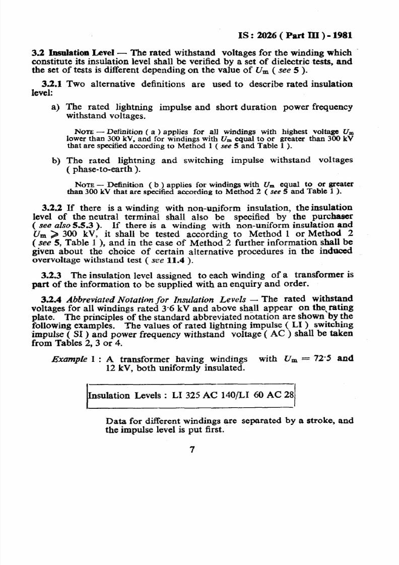
3.2.4 Abbreviated Notation for I nsulation L evels - The rated withstandvoltages for all windings rated 3-6 kV and above shall appear on the,ratingplate. The principles of the standard abbreviated notation are shown by thefollowing examples. The values of rated lightning impulse ( LI ) switchingimpulse ( SI ) and power frequency withstand voltage ( AC ) shall be taken
from Tables 2,3 or 4.
Example 1 : A transformer having windings with U, = 72.5 and12 kV, both uniformly insulated.
Insulation Levels : LI 325 AC 14O/LI 60 AC 28
Data for different windings are separated by a stroke, and
the impulse level is put first.
7
7/28/2019 I S 2026_3r
http://slidepdf.com/reader/full/i-s-20263r 9/45
IS:u)%i(PartrII)-1981
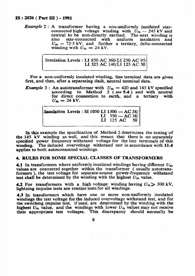
Example 2 : A transformer having a non-uniformly insulated star-connected high voltage winding with U, = 245 kV andneutral to be non-directly earthed. The next winding isalso star-connected with uniform insulation andU, = 72.5 kV, and further a tertiary, delta-connectedwinding with U, = 24 kV.
Insulation Levels : LI 850 AC 360-LI 250 AC 951LI 325 AC 14O/LI 125 AC 50
For a non-uniformly insulated winding, tine terminal data are giventit, and then, after a separating dash, neutral terminal data.
Exmple 3 : An autotransformer with U, = 420 and 145 kV specifiedaccording to Method 2 ( see 5.4 ) and with neutralfor direct connection to earth, and a tertiary withu, = 24 kV.
-Insulation Levels : SI 1050 LI 1300 -AC 38/LI 550 -AC 381LI 125 AC 50
In this example the specification of Method 2 determines the testing ofthe 145 kV winding as well, and this means that there is no separatelyspecified power frequency withstand voltage for the line terminals of thiswinding. The induced overvoltage withstand test in accordance with 11.4applies to both autoconnected windings.
4. RULES FOR SOME SPECIAL CLASSES OF TRANSFORMERS
4.1 In transformers where uniformly insulated windings having different U,,,
values are connected together within the transformer ( usually autotrans-formers ), the test voltage for separate-source power-frequency withstandtest shall be determined by the winding with the highest Urn value.
43 For transformers with a high voltage winding having U,) 300 kV,lightning impulse tests are routine tests for all windings.
4.3 In transformers which have one or more non-uniformly insulatedwindings the test voltage for the induced overvoltage withstand test, and forthe switching impulse test, ifused, are determined by the winding with thehighest Urnvalue, and the windings with lower U rnvalues may not receivetheir appropriate test voltages. This discrepancy should normally be
8
7/28/2019 I S 2026_3r
http://slidepdf.com/reader/full/i-s-20263r 10/45
IS: 2026(PartIII)-1981
accepted. If the ratio between the windings is variably by tappings, thisshould be used to bring the test voltage for the winding with lower U,voltage as close as possible to the appropriate value.
4.4 During switching impulse tests, the voltages developed across differentwindings are approximately proportional to the turns ratios. If ratedswitching impulse withstand voltages are assigned to several windings, theproblem shall be solved as specified in 4.3. A tapped winding of lower U,without assigned switching impulse withstand voltage shall be connected onits principal tapping during the switching impulse test.
45 Series windings in booster regulating transformers, phase shiftingtransformers, etc, where the rated voltage of the winding is only a smallfraction of the voltage of the system, shall have a value of Urn corresponding
to the system voltage.
NW - It is often impracticable to test such transformers in formal compliancewith this specification and it should be agreed between manufacturer and the u&rwhich teats have to be omitted or modified.
5. Y#NSULATION REQUIREMENTS AND DIELECTRIC WITHSTANDTESTS
5.1 The requirements and tests for different categories of windings shall beas given in Table 1.
Nom - The extension of the lightning impulse test to include impulses choppedon the tail is sometimes specified, particularly for cases where the transformer is notprotected by surge arresters. This modification is dealt with in 13.
5.2 Insulation requirements abd dielectric withstand tests for windings withUrn < 300 kV, uniform insulation.
5.2.1 The rated withstand voltages of the winding shall be as follows:
a) A rated short-duration power-frequency withstand voltage in
accordance with Table 2.b) A rated lightning impulse withstand voltage for the line terminals in-
accordance with Table 2.
c) If specified, a rated impulse withstand voltage for the neutralterminal, with the same peak value as for the line materials.
5.2.1.1 For values of Ur n ower than 52 kV there are two lists ofalternatives impulse withstand voltages in Table 2.
For U, = 123, 145, 170, and 245 kV there are different altetitives of
power frequency and impulse withstand voltages in Table.2.
9
7/28/2019 I S 2026_3r
http://slidepdf.com/reader/full/i-s-20263r 11/45
TABLE 2 RATEJXWITHSTAND VOLTAGES FOR TRANSFORMER WINDINGSWITH HIGHEST VOLTAGE FOR EQUIPMENT U, < 300 kV
No,re - The underlined values are preferred in IS : 585-1962 Specification forvoltages and frequency for ac transmission and distribution systems ( revised 1.
The choice between List 1 and List 2 for U, < 52 kV and the choicebetween alternative rated withstand voltages for Urn = 123, 145, 170 and245 kV depends on the severity of overvoltage conditions to be expected inthe system and on the importance of particular installation. Guidance maybe obtained from IS : 2165-1977*. The values chosen should be clearly
stated in the enquiry.
*Specification for insulation coordination ( secmd revision ).
10
7/28/2019 I S 2026_3r
http://slidepdf.com/reader/full/i-s-20263r 12/45
IS:2026(PartIII)-1981
5.2.2 The rated withstand voltages shall be verified by the followingdielectric tests:
4
‘3
4
4
A separate-source power frequency voltage withstand test ( see 10 )( routine test ). This test is intended to verify the power-frequencywithstand strength of the winding under test to earth and otherwindings.
An inducedo vervoltage withstand test ( see 11.2 ) ( routine test ).This test is intended to verify the power frequency withstandstrength along the winding under test, between its phases, and toearth and other windings.
A full-wave lightning impulse test for the line terminals ( see 12 )
( type test ). This test is intended to verify the impulse withstandstrength of each line terminal to earth and other windings, and alongthe winding under test.
NOTE This test becomes a routine test when the winding considered formspart of a transformer of which at least one winding has the highest voltage forequipment U, > 300 kV.
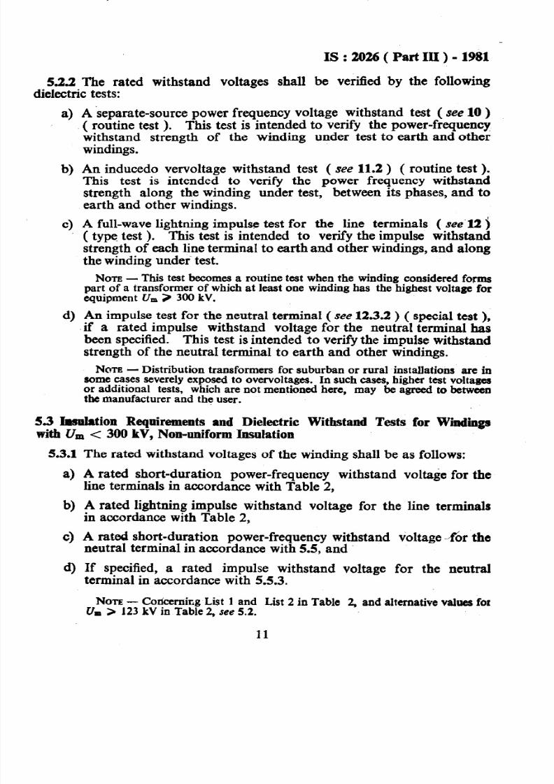
An impulse test for the neutral terminal ( see 12.3.2 ) ( special test ),if a rated impulse withstand voltage for the neutral terminal hasbeen specified. This test is intended to verify the impulse withstand
strength of the neutral terminal to earth and other windings.NATE - Distribution transformers for suburban or rural installations are in
some cases severely exposed to overvoltages. In such cases, higher test voltagesor additional tests, which are not mentioned here, may be agreed to betweenthe manufacturer and the user.
5.3 Insnbtion Requirements and Dielectric Withstand Tests for Windingswith U, < 300 kV, Non-uniform Insulation
5.3.1
a)
b)
c)
d)
The rated withstand voltages of the winding shall be as follows:
A rated short-duration power-frequency withstand voltage for theline terminals in accordance with Table 2,
A rated lightning impulse withstand voltage for the line terminalsin accordance with Table 2,
A rated short-duration power-frequency withstand voltage -%r theneutral terminal in accordance with 5.5, and
If specified, a rated impulse withstand voltage for the neutralterminal in accordance with 5.5.3.
NOTE Concernirg List 1 and List 2 in Table 2, and alternative values forU= > 123 kV in Table 2, see 5.2.
11
7/28/2019 I S 2026_3r
http://slidepdf.com/reader/full/i-s-20263r 13/45
I!3 : 2026 ( Part III ) - 1981
5.3.2 The rated withstand voltages shall be verified by the followingdielectric tests:
a)
b)
4
4
An induced overvoltage withstand test ( see 11) ( routine test ).This test is intend-o to verify the power frequency voltage withstand
strengtk of the lin Lerminals to earth and other windings and thewithstand strength : :r ;ueen the phases and along the winding undertest. The test is carried Jt according to 11.3.
A full-wave lightning im&se test for the line terminals ( see 12 )
( type test ). The purpose of the test is as specified under 5.2.2 ( c ).
NoTE - This test becomes a routine test when the winding considered formspart of a transformer of which at least one winding has the highest voltage forequipment U, > 300 J cV.
A separate-source power-frequency voltage withstand test for theneutral terminal ( see 10 ) (routine test ). This test is intended toverify the power-frequency voltage withstand strength of the neutralterminal to earth.
An impulse test for the neutral terminal ( see 12.3.2 ) ( special test ),if a rated ‘impulse withstand voltage for the neutral terminal hasbeen specified. The purpose of the test is as specified under533(d).
5.4 bulation Requirements and Dielectric )Ilithstand Tests for Windii
with Urn > 300 kV, Non-uniform Insulation - There are two alternative
methods, Method 1 ( see 5.4.1 ) and Method 2 ( see5.4.2 ) for the specifica-tion and testing of transformers which have! winding belonging to thiscategory. Which method has been selected is part of the information to besupplied with an enquiry and with an order, and if Method 2 has beenselected it is also necessary to indicate the choice between alternativeprocedures in the induced overvoltage withstand test ( see 11.4 ).
M ethod 1 - For specifying and testing this method makes use of ratedlightning impulse withstand voltage and a rated short-duration power-
frequency withstand voltage. The latter is also intended to represent asu5cient withstand strength against switching impulse voltages ( see 5.4.1).
Meihod 2 - For specifying and testing this method makes use of a ratedswitching impulse withstand voltage and a rated lightning impulse withstandvoltage. The induced power-frequency overvoltage test is related only tostresses under normal operating conditions and temporary overvoltages.The induced voltage test procedure specified differs from that of Method 1in that the duration is longer, the test voltage phase-to-earth is lower, andthe test criterion is based on the measurement of partial discharges in the
transformer ( 8ee 5.42 ).
12
7/28/2019 I S 2026_3r
http://slidepdf.com/reader/full/i-s-20263r 14/45
IS:2026(PartIII)-1981
5.4.1Method 1
5.4.1.1 The rated withstand voltages of the winding shall be as follows:
a) A rated short-duration power-frequency withstand voltage for lineterminals in accordance with Table 3;
b) A rated lightning impulse withstand voltage for line terminals, inaccordance with Table 3;
c) A rated short-duration power-frequency withstand voltage forneutral terminal, in accordance with 5.5; and
d) If specified, a rated lightning impulse withstand voltage for neutralterminal, in accordance with 5.5.3.
5.4.1.2 The withstand voltages shall be verified by the followingdielectric tests:
a) An induced overvoltage withstand test ( see 11) ( routine test ).The test is carried out in accordance with 11.3. The purpose of thistest is as specilkl under 5.3.2 ( a ).
b) A full-wave lightning impulse test for the line terminals ( see l2)( routine test ). The purpose of this test is as specified under5.2.2( c ).
TAB= 3. TEST VOLTAGES FOR LINE TERMINALS OF WINDINGS WITH&, 2 300 kV, SPECIFIED IN ACCORDANCE WITH METHOD 1
( Clauses 3.1.1, 3.2.4 and 5.4.1.1 )
HI- VOLTAOE RATEDSHORT-DURATION RATED hXiTlWW
KBREQIJIPMENT POWER-FREQUENCY
ulu WITHSTAND OLTAGE rm~:LE7~
(1) (2) (3)
kV rms kVrms kV peak
300
{
395 950460 1050
362
{
460 1050510 1 175
420
{
570 1300-630 1 425
Non 1 - The underlined value is the preferred value in IS : 585-1962 Speciticationfor voltages and frequency for ac transmission and distribution systems ( revised ).
NOTES- Guidance for the choice between alternative rated withstand ~01tagtcombinations may be obtained from IS : 2165-1977 Specification for insulation Co-ordination ( seeold revisfon ).
I
7/28/2019 I S 2026_3r
http://slidepdf.com/reader/full/i-s-20263r 15/45
7/28/2019 I S 2026_3r
http://slidepdf.com/reader/full/i-s-20263r 16/45
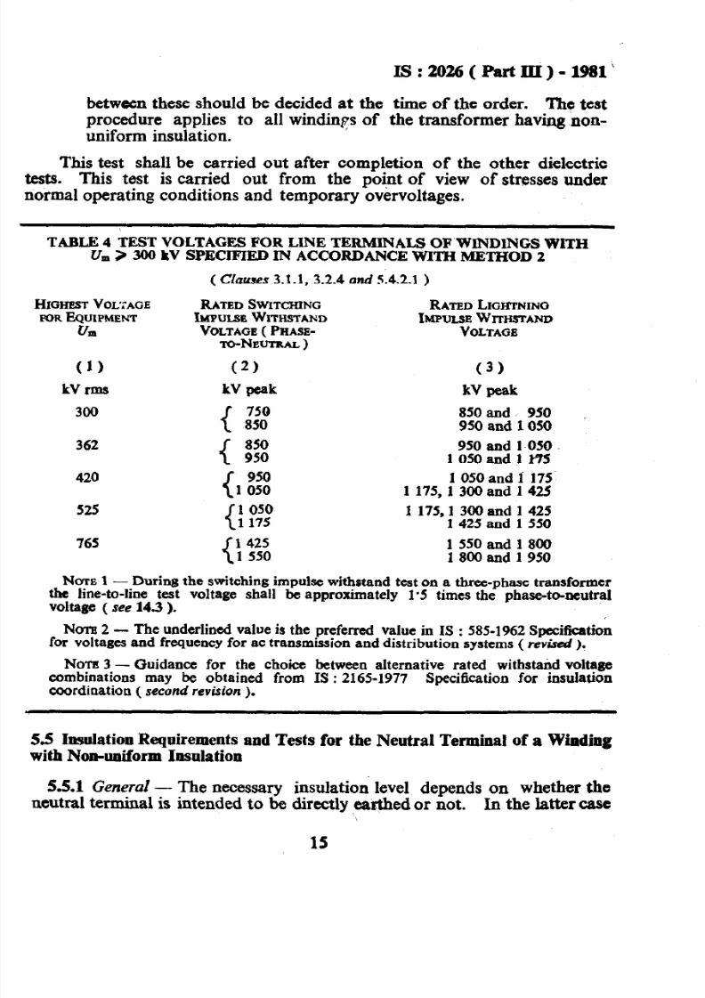
between these should be decided at the time of the order. The testprocedure applies to all windings of the transformer having non-uniform insulation.
This test shall be carried out after completion of the other dielectrictests. This test is carried out from the point of view of stresses undernormal operating conditions and temporary overvoltages.
TARLR 4 TEST VOLTAGES FOR LINE TERMINALS OF WINDINGS WITHU, > 300 LV SPECIFIED IN ACCORDANCE WITH METHOD 2
(Clauses 3.1.1, 3.2.4 and 5.4.2.1 )
HIGHESTVOLTAGEFOREQUIPMENT
u*
(1)
kVrms
300
362
420
525
RATED SWITCHINGIMPULSBWITHSTANDVOLTAGE PHASE-
m-Newr~~~)
(2)
kV peak
{
750850
{ f:X
{
9501 050
: z
RATED LIGHTNINOIMPULSEWITHSTAND
VOLTAGE
(3)
kV peak
850 and 950950 and 1050
950 and 1 050105Oandlk75
1 050 and 1 1751175,13OOand1425
1 175,l 300 and 1 4251 425 and 1 550
155Oand180018OOand1950
765 1 4251 550
Ncm 1 - During the switching impulse withstand test on a three-phase transformerthe line-to-line test voltage shall be approximately 1’5 times the phase-t&neutralvoltage ( see 14.3 ).
Nom2 - The underlined value is the preferred value in IS : 585-1962 Specificationfor voltages and frequency for ac transmission and distribution systems ( rev&d ).
NOTE 3 - Guidance for the choice between alternative rated withstand voltagecombinations may be obtained from IS : 2165-1977 Specification for insulationcoordination ( second revision ).
5.5 Insulation Requirements and Tests for the Neutral Terminal of a Windingwith Non-uniform Insulation
5.5.1 General - The necessary insulation level depends on whether theneutral terminal is intended to be directly earthed or not. In the latter case
‘\
15
7/28/2019 I S 2026_3r
http://slidepdf.com/reader/full/i-s-20263r 17/45
IS:2026( PartII)-1981
an overvoltage protective device should be installed on the neutral terminalin order to limit transient over voltages otherwise non-uniform insulationof the winding is not recommended.
NOTE- 55.2 and 5.5.3 deal with determination of the necessary minimum with-stand voltage for the neutral terminal. An increase of the value may sometimeseasily be arranged and can improve the interchangeability of the transformer in thesystem. It may also be necessary to design the winding with higher neutral insulationlevel because of the test connection to be used for the induced power-frequency test ofthe transformer ( see 11.3 ).
5.5.2 Neutral Terminal I ntended to be Di rectly Earthed - This i neutralterminal which is permanently connected to earth directly or through acurrent transformer but without any intentionally added impedance in the
connection.5.5.2.1 In this case the short-time power-frequency withstand voltage
shall be at least 38 kV.
5.5.2.2 No impulse test on the neutral terminal is recommended.During impulse tests on a line terminal the neutral terminal shall be connec-ted directly to earth.
5.53 Neutral Terminal not Intended to he Directly Earthed - This isneutral terminal which is not permanently in direct connection to earth.
This may be connected to earth through a considerable impedance ( forexample, arc-suppression coil earthing ). Separate phase-winding neutralterminal may be connected to a regulating transformer. The rated voltageof the surge arrester which is to be installed for neutral protection.shall beselected at least equal to the maximum power-frequency voltage under suchconditions of system faults as are considered.
5.5.3.1 It is the responsibility of the user to select the overvoltageprotective device, to determine its impulse protection level, and to specifythe corresponding impulse withstand voltage for the neutral terminal of thetransformer; A suitable standard value should preferably be selected from
Table 2. The corresponding rated power-frequency withstand voltage fromthe table shall also apply. It should be checked that the power-frequencywithstand voltage is greater than the above mentioned system-fault voltage.
553.2 The rated impulse withstand voltage of the neutral terminal isverified by either of the two tests described under 12.3.2. A chopped-waveimpulse test on the neutral is not recommended.
6. TESTS ON A TRANSFORMER WiTH A TAPPED WINDING
6.1 If the tapping range is rt5 percent or less, the dielectric test shall bedone with the transformer connected on the principal tapping.
16
7/28/2019 I S 2026_3r
http://slidepdf.com/reader/full/i-s-20263r 18/45
IS : 2026 ( Part III ) - 1981
4~2 If the tapping range is larger than f5 percent, the choice of tappingcannot\be prescribed universally. Testing conditions determine the choiceof tappmg required for induced power-frequency test and for switchingimpulse test ( see 4 ).
6.3 Under lightning impulse test the dielectric stresses are distributeddifferently depending on the tapping connection and general design of thetransformer. Unless impulse testing on a particular tapping has beenagreed, the two extreme tappings and the principal tapping shall be used,-one tapping for each of the three individual phases of a three-phase trans-ray or the three single-phase transformers designed to form a three-phase
7. INSULATION REQUIREMENTS AND TEST CONDITIONS FORDRY TYPE TRANSFORMERS
7.0 Pending preparation of a separate standard for dry type transformersthe provisions of 7.1 shall apply.
7.1 Dry type transformers are not a uniform category with respect toinsulation requirements and tests. The clauses of thi’s standard are applica-ble when dry type transformers are intended for general power distributio%in public or industrial systems. They are then designed in accordancewith 5.2 and Table 2 ( List 1 or 2 ).
However, for application in particular systems where the insulationrequirements are lower than in general, and where this has been proven byexperience, dry type transformers not designed for impulse type tests andwith even lower power frequency test voltage may be applied. No definite
. figures are recommended here.
8. REPEATED DIELECTRIC TESTS
8.1 lf a transformer has already withstood complete dielectric acceptancetests according to this standard, in accordance with 5.2, 5.3 or 5.4.1, andsubsequently. acceptance tests are to be repeated, the test voltage levels shallbe reduced to 75 percent of the original values, unless otherwise agreed, and
provided that the internal insulation has not been modified in the meantime.
NOTE The rule does not apply to the induced power freqbency overvoltage test( see 11.4 ) on transformers specified in accordance with 5.4.2.
9. INSULATION OF AUXILIARY WIRING
9.1 Unless otherwise specified, the wiring for auxiliary power and controlcircuitry shall be subjected to a one-minute,power-frequency withstand testwith 2-O kV rms to earth. Motors andequipment shall fulfil insulation requirements
apparatus for auxiliaryto the relevant
17
7/28/2019 I S 2026_3r
http://slidepdf.com/reader/full/i-s-20263r 19/45
IS,:2026(PartIII)- 1981
zhdian Standards ( which are generally lower than the value specified for the,wiring alone and which may sometimes make it necessary to disconnect themin order to test the circuits ).
NATE- Auxiliary e uipment for large transformers is usually dismantled forshipment. After camp etion of erection on site a 1 000 V megohm meter test isf
recommended.
10. SEPARATE-SOURCE VOLTAGE WITHSTAND TEST
10.1 he separate-source voltage jest shall be made with single-phasealternating voltage as neaily as possible to the sine-wave form and of anyconvenient frequency not less than 80 percent of the rated frequency.
10.2 The peak value of voltage shall be measured. The peak value divided _
by l/r shall be equal to the test value.
10.3 The test shall be commenced at a voltage not greater than one-third ofthe specified test value and shall be increased to this value as rapidly as isconsistent with measurements. At the end of the test, the voltage s-1 bereduced rapidly to less than one-third-of the test value before switching off.
10.4 The full test voltage shall be applied for 60s between the winding uhdertest and all terminals of the remaining windings, core, frame and tank orcasing of the transformer, connected together to earth.
10.5 The test shall be successful if no collapse of the test voltage occurs.
No-m - On windings with non-uniform insulation the test shall be carried out withonly the test voltage specified for the neutral terminal, The line terminals thereforereceive a modified induced overvoltage test in accordance with 11.3 or 11.4.
11. INDUCED OVERVOLTAGE WITHSTAND TEST
11.1 General - The test shall be carried out in three alternative ways inaccordance with 11.2, 11.3, or 11.4 for different categories of windings.
11.1.1 An alternating voltage shall be applied to the terminals of onewinding of the transformer. The voltage shall be, as nearly as possible, to
the sine-wave form and of a frequency suitably increased above the ratedf&quency to avoid excessive excitation current during the test.
+ 11.1.2 The peak value of the induced test voltage shall be measured. The
peak value divided by d2-shall be equal to the test value.
11.13 The test shall_ be qommenced at a voltage not greater than one-- third of the test value and Wall be increased to the test value as rapidly as is
consistent with measurement. At the end of the test, the voltage shall bereduced apidly to lessthan one-third of the test value before switching off.
18
7/28/2019 I S 2026_3r
http://slidepdf.com/reader/full/i-s-20263r 20/45
11.1.4 Unless otherwise specified in the subsequent clauses, the durationof the test at full test voltage shall be 60s for any test frequency up to andincluding twice the rated frequency. When the test frequency exceeds twice
the rated frequency, the duration of the test shall be120 x rated frequency
test frequencyseconds,
but not less than I5 seconds.
11.2 Induced Overvoltage Withstand Test for Transformers with UoiformIyInsulated High-Voltage Winding - The test voltage across an untappedwinding of the transformer shall be equal to twice the ratedvoltage, but theline-to-line test voltage of any three-phase winding shall not exceed the
rated withstand voltage as given in Table>2, co1 2.11.2.1 A three-phase winding shall preferably be tested with symmetrical
three-phase voltages induced in the three winding phases. If the windinghas a neutral terminal, this may be earthed during the test.
11.2.2 The test shall be successful if no collapse of the test voltage o&irrs.
11.3 Iodnced Phase-@Ear&b Overvoltage Withstand T&for Transformer withNon-uniformly Insulated High-Voltage Windings - Urn -c 300 kV ( see 5.3 ),or U,,, ) 300 kV, specified according to Method 1 ( see 54.1).
113.1 The line terminals shall receive the test voltage value specified inthe appropriate table.
11.3.2 On single-phase transformers the test is normally carried. out with,the neutral terminal earthed. If the ratio between the windings is variableby tappings, this should be used to satisfy test voltage conditions on differtntwindings simultaneously as far as possible. In exceptional cases ( see 4 )the voltage on the neutral terminal may be raised by, connection to anauxiliary booster transformer. Another winding of the transformer undertest may also be connected in series with the high voltage winding.
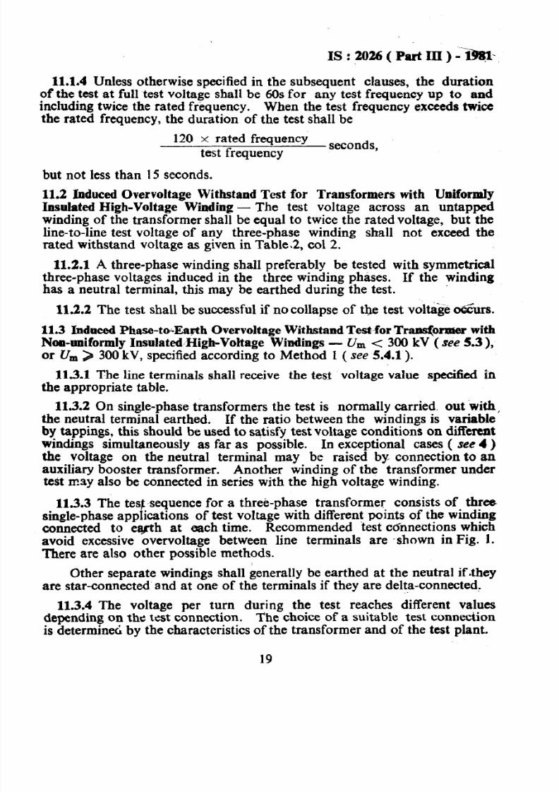
11.3.3 The test,sequence for a three-phase transformer consists of threesingle-phase applications of test voltage with different points of the windingconnected to ewh at each time. Recommended test cdnnections whichavoid excessive overvoltage between line terminals are -shown in Fig. 1.There are also other possible methods.
Other separate windings shall generally be earthed at the neutral iftheyare star-connected and at one of the terminals if they are delta-connected.
11.3.4 The voltage per turn during the test reaches different values
depending on the test connection. The choice of a suitable test connectionis determined by the characteristics of the transformer and of the test plant.
19
7/28/2019 I S 2026_3r
http://slidepdf.com/reader/full/i-s-20263r 21/45
IS : 2026 Pait III ) - 1981
NOTE - In the case of transformers with domplicated windings arrangements it isrecommended that the complete connection of all windings during the test should bereviewed between manufacturer and user at the contract stage so that the testrepresents a realistic service stress combination as far as possible.
113.5 The test is successful if no collapse of the test voltage occurs.
u/3 u 0
UlTi@
wl
00 u 0 0,II=4
4
u 0 0
IH/J u 0 0
L!uT’
IIJCO3
“a-“t1-W =
Un, Un2
“t =U2. Unl-U. Unr
Un, Un2
I%. 1 CONNECTIONS FOR SINGLE-PHASE INDUCED OVERVOLTAGE
WITHSTAND TESTS ON TRANSFORMERSWITH
NON-UNIFORM INSULATION
NOTE 1 - Connection ( a ) may be used when the neutral is designed to withstand atkast one-third of the voltage U. Three different generator connections to the lowvoltage winding are shown. Only ( al ) is possible, if the trapsformer has unwoundmagnetic return paths ( shell form or five-limb core form ).
NOTE 2 - Coonectioo (b ) is possible and recommended for three-phase trans-formers having unwound magnetic return paths for the flux in the tested limb. Ifthere is a delta-connected winding, it has to be open during the test.
Nore3- Connection ( c ) shows an auxiliary booster transformer, which gives abias voltage XJ, at the neutral terminal of an auto-transformer under test. Ratedvoltages of the two auto-connected windings are U,,, U,,, and the corresponding testvoltages, VI, u,. This connectioo may also be used for a three-phase transformer
without unwound magnetic return paths having the neutral insulation designed for less,th@one-third of the voltage II.
20
7/28/2019 I S 2026_3r
http://slidepdf.com/reader/full/i-s-20263r 22/45
IS : 2026 ( Part III) - 1981
11.4 Induced Overvoltage Withstand Test for Transformers with Non-uniformly Insulated High-Voltage Windings, 17, > 300 kV, SpecifiedAccording to Method 2 ( 5.4.2 )
11.4.i The test applies to all non-uniformly insulated windings_ of thetransformer, regardless of whether they are auto-connected or separate.
11.4.2 The- neutral terminal of the winding under test shall be earthed.For other separate windings, if they are star-connected they shall be earthedat the neutral, and if they are delta-connected they shall be earthed at oneof the terminals.
A three-phase transformer shall be tested either phase by phase in asingle-phase connection that gives voltages on the line terminals as shownin Fig. 2, or in symmetrical three-phase connection. The choice shah beagreed between the parties at the time of placing the order.
U -o*su -0.50
iii
I-I 1 1
FIG. 2 CONNECTIONS FOR INDUCED OVERVOLTAGEWITHSTAND TESTONNON-UNIFORMLY INSULATED I-~GH VOLTAGE WINDING
ACCORDING TO METHOD 2
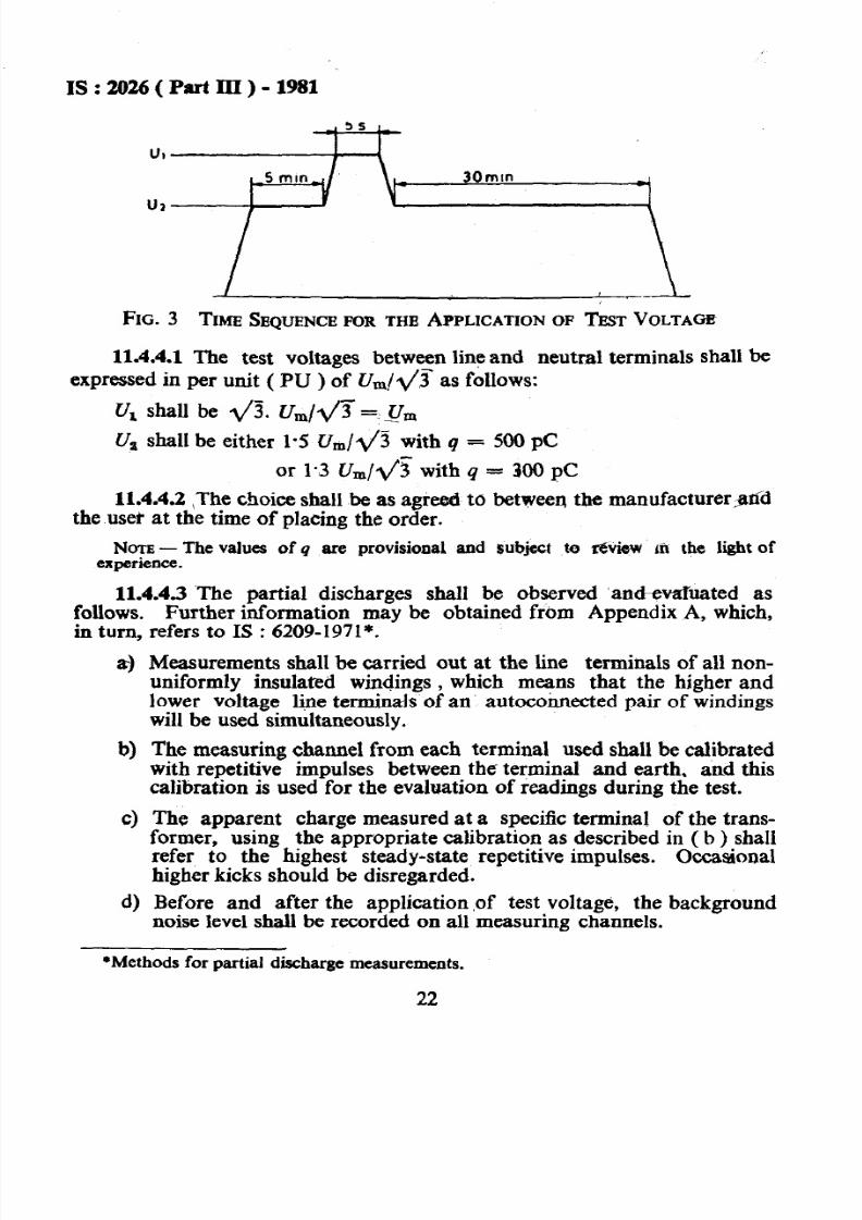
11.4.3 The time sequence for the application of test voltage shall, be asshown in Fig. 3. The voltage shall be switched on at a level not higher thanone-third of U,, raised to Uz, held there for a duration of 5 min, raised toU,, held there for a duration of 5 seconds, immediately reduced againwithout interruption to U, , eld there for a duration of 30 min, and reducedto a value below one-third of U, efore switching off.
14.4.3.1 The duration of the test shall be independent of the testfrequency.
11.4.4 During the whole application of test voltage partial discharge shallbe monitored as described below. The apparent charge shall not be higherthan a specified value q.
21
7/28/2019 I S 2026_3r
http://slidepdf.com/reader/full/i-s-20263r 23/45
IS:2026(PartIII)-1981
FIG. 3 TIME SEQUENCE IR THE APPLICATIONOF TEST VOLTAGE
11.4.4.1The test voltages between line and neutral terminals shall be
expressed in per unit ( PU ) of U,,J@ as follows:
Uz shall be either l-5 Um/ l / j with q = 500 PC
or 1.3 Ur n/ q5with q = 300 pC
11.4.4.2The choice shall be as agreed to between the manufactureraddthe user at the time of placing the order.
NOTE The values of q are provisional and Sttbje4 te Tevidw ~h the lit of
experience.
11.4.4.3 The partial discharges shall be observed ‘andevahrated as, Further information may be obtained from Appendix A, which,ollows.
in turn,
a)
refers to IS : 6209-1971*. --_
Measurements shall be carried out at the line terminals of all non-uniformly insulated windings , which means that the higher andlower voltage li,ne terminals of an autoconnected pair of windingswill be used simultaneously.
b)
4
d)
The measuring channel from each terminal used shall be calibratedwith repetitive impulses between the terminal and earth, and thiscalibration is used for the evaluation of readings during the test.
The apparent charge measured at a specif?c terminal of the trans-former, using the appropriate calibration as described in ( b ) shallrefer to the highest steady-state repetitive impulses. Occasionalhigher kicks should be disregarded.
Before and after the application of test voltage, the backgroundnoise level shall be recorded on all measuring channels.
*Methods for partial discharge measurements.
22
7/28/2019 I S 2026_3r
http://slidepdf.com/reader/full/i-s-20263r 24/45
e)
f-l
g)
h)
3
IS:2026(PartIII)-1981
The background noise level shall be lower than half the specifiedlimit for apparent charge q.
During the raising of voltage up to level U, and reduction from U,down again, possible inception and extinction voltages shall benoted.
A reading shall be taken and noted during the first period atvoltage U,.Observations during the short application of voltage lJz shall not berequired.
During2h
edischarg
whole of thes econd period at voltage U,, the partiallevel shall be continuously observed and readings at
intervals noted or recorded.
11.4.4.4 The test shall be successful, if:
4
W
No collapse of the test voltage occurs,
The continuous level of apparent charge q during the last 29 of the3Q min application of voltage U, stays below the specified limit inall the measuring channels, and does not show a sign&ant, steadilyrising trend near this limit.
If the apparent charge reading rises above the specified limit for a
significant time and then returns below this level again the test maycontinue without interruption until acceptable readings have beenobtained for 30 min. Occasional high kicks should be disregarded.
NOTE - As long as no breakdown occurs, and unless very high partiaI&-charges are’sustained for a long time the test shall be regarded as non-destruc-tive. A failure to meet the partial discharge acceptance criterion shall, therefore,not warrant immediate rejection but lead to consultation between user andmanufacturer about further investigation. Suggestions for such procedures aregiven in Appendix A. Difliculties concerning the bushings are mentioned in 2.
.
12. LIGHTNING rir;rPULSE TEST
12.1 General - The impulse generator circuit, impulse shape measuringequipment and calibration method shall be in accordance with IS : 2071( Part I)-1974*, IS : 2071 (Part II)-1974t and IS : 2071 (Part III )-1976#.
121.1 For oil-immersed transformers the test voltage chosen shallnormally be of negative polarity, because this reduces the risk of erraticexternal flashover in the test circuit.
*Methods of hi voltage testing: Part I General detbritions and test requirementa( firsf revision ).
*Methods of high voltage testing: Part II Test procedures (first revision ).$Methods of high voltage testing: Part III Measuring devices ( fi rst revision ).
23
7/28/2019 I S 2026_3r
http://slidepdf.com/reader/full/i-s-20263r 25/45
I S : 2026 ( Part III ) - 1981
12.1.2 Bushing spark gapsprevent sparkover during the
may be removed or their spacing increased totest.
12.1.3 When non-linear elements or surge diverters - built into the trans-
former or external - are installed for the limitation of transferred overvol-tage transients, the impulse test procedure shall be discussed in advance foreach particular case. If such elements are present during the test, theevaluation of test records may be difficult ( see 12.5)
12.1.4 The test impulse shall be a full standard lightning impulsel-2 f 30 percent/50 f 20 percent microseconds.
12.1.5 There are cases, however, where this standard impulse shape cannot reasonably be obtained, because of low winding inductance or high
capacitance to earth. The resulting impulse shape is then often oscillatory.Wider tolerances may, in such cases, be permitted by agreement between theparties. The amplitude of opposite polarity of an oscillatory impulseshould not exceed 50 percent of the first amplitude.
The impulse shape problem may also be treated by alternative methodsof earthing during the test ( see 12.3 ).
12.1.6 The impulse circuit and measuring connections shall remainunchanged during calibration and full voltage tests.
12.2 Test Sequence - The test sequence shall consist of one impulse of avoltage between 50 percent and 75 percent of the full test’ voltage, and threesubsequent impulses at full voltage. If during any. of these applications an Iexternal flashover in the circuit or across a bushing gap should occur, or ifthe oscillographic recording should fail on any of the specified measuringchannels, that application shall be disregarded and a further applicationmade.
12.2.1 Additional impulses at amplitudes not higher than 50 percent maybe used but need not be shown in the report of the test.
123 Termind Comtections
123.1 Terminal Comiectiom Dur ing Tests on Line Terminah
12.3.1.1 The impulse test-sequence is applied to each of the lineterminals of the tested winding in succession. In the case of a three-phasetransformer, the other line terminals of the winding shall .be eartheddirectly or through a low impedance, such as a current measuring shunt.
123.13 If the winding has a neutral terminal, the neutral shall beearthed directly or through a low impedance, such as a current measuringshunt. The tank shall be earthed.
24
7/28/2019 I S 2026_3r
http://slidepdf.com/reader/full/i-s-20263r 26/45
123.13 In the case of a separate-winding transformer, terminals ofwindings not under test are likewise earthed directly or through impedancesso that under all circumstances the voltage appearing on them is limited to
less than 75 percent of their rated withstand voltage.12.3.1.4 In the case of an auto-transformer, when testing the line
terminals of the high-voltage winding, it may happen that the standardimpulse wave-form can not reasonably be obtained if the line terminals ofthe common winding are earthed directly or through a current measuringshunt. The same applies to the testing of the line terminals of the oommonwinding if the line terminals of the high-voltage winding are earthed. It isthen permissible to earth the non-tested line terminals through resistors notexceeding 400 ohms. On the other side the voltages appearing on the non-
tested line terminals to earth should not exceed 75 percent of their ratedlightning impulse withstaad voltage.
12.3.15 With impulse testing windings with low impedance it is difficultto obtain correct impulse shape on the tested terminals. In this case widertolerances may be applied by agreement between the parties ( see 12.15 ).It is also possible to simplify the problem by earthing the no&testedterminals of the winding through resistors. The resistance value shall notbe higher than 500 ohms and shall be chosen so that the voltage appearingon the terminals- is limited to not more than 75 percent of their rated with-stand voltage. Alternatively by agreement at the time of placing the orderthe transferred surge method in accordance with 12.3.3 may be employed.
Exceptions from this main procedure are given under 12.3.2 and 12.33.
123.2 I mpulse Test on a Neutral Terminal
12.3.2.1 When the neutral terminal of a winding has a rated impulsewithstand voltage it may be verified by an impulse test ‘applied through anyone of the line terminals or through all three line terminals of a three-phasewinding connected together. The neutral terminal is connected to earth
through an impedance, and the voltage amplitude developed across thisimpedance when a -standard lightning impulse is applied to the line terminalshall be equal to the rated withstand voltage of the neutral terminal. Theamplitude of the impulse applied to the line terminal is not prescribed butshall not exceed 75 percent of the rated lightning impulse withstand voltageof the line terminal.
12.3.2.2 As an alternative an impulse test corresponding to the ratedwithstand voltage of the neutral may be applied directly to the neutral withal1 line terminals earthed. In this case. however, a longer duration of the
front time is allowed-up to 13 microseconds.
-25
7/28/2019 I S 2026_3r
http://slidepdf.com/reader/full/i-s-20263r 27/45
12.33 Tr an.$erred Surge Method
12.3.3.1 When the low voltage winding cannot in service be subjectedto lightning overvoltages from the low voltage system, this winding may byan agreement between the manufacturer and the user, be impulse-tested withsurges transferred from the high voltage winding. A guidance for thispurpose is provided in Appendix B.
1233.2 This method is justified when the design is such that animpulse directly applied to the low voltage winding could result in unrealis-tic stressing of higher voltage windings, particularly when there is a largetapping winding physically adjacent to the low voltage winding.
12.333 In applying the transferred surge method, the tests on the low
voltage winding are carried out simultaneously with the impulse tests on theadjacent higher voltage winding. The line terminals of the low voltagewinding are connected to earth through resistances of such value that theamplitude of transferred impulse voltage between line terminal and earth orbetween different line terminals or across a phase winding is as highas possible but not .exceeding the rated impulse withstand voltage. Theresistance shall not exceed 5 000 ohms. The wave at the low voltage windingterminals may have any shape and shall be acceptable.
12.3.3.4 The details of the procedure shall be agreed before the test.
12.4 Records of Test
12.4.1 The oscillographic recordes obtained during calibrations and testsshall clearly show the applied voltage impulse shape ( front time, time tohalf value ).
12.4.2 At least one more measurement channel shall be used. In mostcases an oscillogram of the current flowing to earth from the tested windingwill present the best sensitivity for fault indication. The current flowingfrom tank to earth, or the transferred voltage in a non-tested winding are
examples of alternative suitable measuring quantities.
12.5 Test Criteria - The absence of significant differences between voltageand current transients recorded at reduced voltage and those recorded at fulltest voltage constitute evidence that the insulation has withstood the test.
NOTE1 -The detailed interpretation of the oscillographic test records anddiscrimination of marginal disturbances from true records of failure require a greatdeal of skill and experience.
No.1732 If there is doubt about the interpretation of possible discrepanciesbetween o~~ill~~arns, hree subsequent impulses at full voltage shall be applied, or
the wfiole impulse test on the terminal shall be repeated.
7/28/2019 I S 2026_3r
http://slidepdf.com/reader/full/i-s-20263r 28/45
Is:2026(PartIII)-.19&I
NOTE3 -Additional obs&iitions during the test (smmd effect, etc) may beused to confirm the oacilIogra~hic rawrds, but they do not cotwitutc evidawe iathCUlSdVeS.
13. TEST WITH LIGHTNING IMPUISE, CHOPPED ON ‘ITIETAIL
13.1 General - This test is a special test to be carried out on line terminalsof a winding. When it has been agreed to carry out this test it shall becombined with the full lightning impulse test in the manner described below.The peak value of the chopped impulse shall be the same as for the fullimpulse.
Usually, the same settings of the impulse generator and measuringequipment are used, and only the chopping gap equipment is added. Thestandard lightning impulse sl.$l have a time to chopping between 2 to 6
microseconds.
13.2 Chopping Gap md Characteristics of the Chopping - The use of atriggered-type chopping gap with adjustable timing is recommendedalthough a plain rod-rod gap is allowed. The chopping circuit shall be soarianged that the amount of overswing to opposite polarity of the rdedimpulse will be limited to not more than 30 percent of the z?mplitu of thechopped impulse.
13.3 Test Sequence and Test Criteria - As indicated under 13.1, this test iscombined with full impulse test in a single sequence. The recommended
order of the different pulse applications is:
a) one reduced full impulse,
b) one 100 percent full impulse,
c) one or more reduced chopped impulses,
d) two 100 percent chopped impulses, and
e) two 100 percent full impulses.
13.3.1 The same types of measuring channels and oscillograms as for thefull impulse test ( see 12 ) shall be used.
13.3.2 In principle, the detection of faults during a chopped impulse testdepends essentially on a comparison of the oscillographic records of 100percent and reduced chopped impulses. The neutral current record ( or anyother supplementary recording ) presents a superposition of t&sientphenomena due to the front of the original impulse and from the chopping.Account should therefore be taken of the possible variations, even slight, ofthe chopping time delay. The latter part of the oscillation pattern is then
modified, and this effect is difficult to separate from the record of a fault.
27
7/28/2019 I S 2026_3r
http://slidepdf.com/reader/full/i-s-20263r 29/45
1333 The recordings of successive 100 percent full impulse tests con&i-
tute a supplementary criterion of a fault, but they do not constitute inthemselves a quality criterion for the chopped impulse test.
14. SWITCHING IMPULSE TEST
14.1 General
14.1.1 Measuring equipment and calibration methods shall be in accord-ance with 1s : 2071 ( Part I )-1974*. The test is a routine test for windingswith & > 300 kV specified according to Method 2 ( see 5.4.2 ).
14.13 The impulses shall be applied either directly from the impulse
voltage source to a line terminal of the winding under test, or to a lowervoltage winding so that the test voltage is inductively transferred to thewinding under test. The specified test voltage shall appear between line -andneutral terminals and the neutral shall be earthed. In a three-phase trans-former the voltage developed between line terminals during the test shahbeapproximately 1.5 times the voltage between line and neutral termi,nals( see 143 ).
14.13 The test voltage should normally be of negative polarity becausethis reduces the risk of erratic external Sashover in the test circuit.
14.1.4 The voltage developed across different windings of the transformerare approximately proportional to their effective numbers of turns, and the.$est voltage shall be determined by the winding with the highest U, value#*e 4).
.X4.1.5 The voltage impulse shall have a virtual front time of at least 20
z&l‘croseconds, a time above 90 percent of the specified amplitude of at least
microseconds, and a total duration from the virtual origin to the firstzero passage of at least 500 microseconds.
NOTE - The impulse form is purposely different from the standard waveshape of25012 500 microseconds.
NOTE - TKe front time shah be selected by the manufacturer so that the voltagedistribution along the winding under test will be essentially uniform. Its value isusually less than 250 microseconds.the magnetic circuit.
During the test considerable flux is developed mThe impulse voltage can be sustained up to the instant when
the core reaches saturation and the magnetizing impedance of the possible impulseduration can be increased by introducing remanence of opposite polarity before eachfull voltage test impulse. This is accomplished by lower voltage impulses of simflarshape but opposite polarity or by temporary connection to a dc voltage source.
*Methods of high voltage testing: Part I General de&&ions and test requjrements( jirst rfrvtiorr .
28
7/28/2019 I S 2026_3r
http://slidepdf.com/reader/full/i-s-20263r 30/45
IS:2026(PartIII)-1981
14.2 Test Seqaence and Records - The test sequence shall consist of oneimpulse ( calibration impulse ) of a voltage between 50 percent and 75 per-cent of the full test voltage and three subsequent impulses at full voltage. If
the oscillographic recording should fail, that application shall be disregardedand a further application made. Oscillographic records shall be obtainedof at least the impulse wave-shape on the line terminal under test.
143 Terminal Connections
14.3.1 During the test the transformer shall be in a no-load condition inorder to present &Sent impedance. Windings not used for the test shallbe suitably earthed at one point but not short-circuited. For a single-phasetransformer the neutral of the tested winding shall be earthed.
143.2 A three-phase winding shall be tested phase by phase with theneutral terminal earthed and with the transformer so connected that avoltage of opposite polarity and about half amplitude appears on the tworemaining line terminals ( see Fig. 2 ).
1433 Bushing spark gaps and additional means for limitation of over-voltages shall be as specified for the lightnipg impulse test ( see 12.1 1.
144 Test riteriaF
- The test is successful if there is no sudden collapse ofvoltage ind cated on the oscillograms.
NOTE However, the successive osdosrams may be different because of theinfluence of magnetic saturation on impulse duration.
14.4.1 Additional observations during the test ( abnormal sound effects,etc ) may be used to confirm the oscillographic records, but they do notconstitute evidence in themselves.
15. INFORMATION REQUIRED WITH ENQUIRY AND ORDER
15.1 The technical information on insulation and dielectric tests to besupplied with the enquiry and order is given in Appendix C.
29
7/28/2019 I S 2026_3r
http://slidepdf.com/reader/full/i-s-20263r 31/45
IS:24mi(PartIu)-198l
APPENDIX A
( Clauses 2.5, 11.4.4.3 and 11.4.4.4 )
APPLICATION GUIDE FO ’ PARTIAI, DISCHARGE
MEASUREMENTS DURING &D UCED OVERVOLTAGE
WITHSTAND TEST ON TRANSFORMERS
A-l. INTRODUCI’ION
A-l.1 A partial discharge ( PD ) is an electric discharge that only partially
bridges the insulation between conductors.
In a transformer such a partial discharge causes a transient change ofvoltage to earth, at every externally available winding terminal.
A-l.2 Measuring impedances are connected effectively between the earthedtank and the terminals, usually through a bushing tap or through a separatecoupling capacitor as described under A-2.
A-1.2.1 The actual charge transferred at the site of a partial discharge
cannot be measured directly. The preferred measure of the intensity of apartial discharge is the apparent charge, q, as defined in 23.1 of IS : 6209-1971*.
A-1.22 The apparent charge, q, related to any measuring terminal isdetermined by a suitable calibration ( see A-2 ).
A-l.23 A particular partial discharge gives rise to different values ofapparent charge at different terminals of the transformer. The comparisonof simultaneously collected indications at different terminals may give
information about the location of the partial discharge source within thetransformer ( see A-5 ).
A-$2.4 The acceptance test procedure specified in the standard calls formeasurement of apparent charge at the winding line terminals.
This is considered to give sufficiently ‘good sensitivity to arbitrarydischarge sources irrespective of location, provided that the recommenda-_tions below are observed. The specified, tentative acceptance values ofapparent charge are based on practical experience from partial discharge
measurements on transformers which have in addition passed traditional acdielectric tests.
*Methods for partial discharge measuremqnts.
2 30
7/28/2019 I S 2026_3r
http://slidepdf.com/reader/full/i-s-20263r 32/45
rs;2026(PartIII)+m
A-2. CONNECTION OF MEASURING AND CAtiBRATION CIRCUI’I’S- CALIBkATION PROCEDURE
A-2.1 Themeasuring equipment is connected to the terminals by matchedcoaxial cables. The measuring impedance in its s’ plest form is thematching impedance.of the cable which may, in turn, be he input impedanceof the measuring instrument.
A-2.2 Inorder to improve the signal-to-noise ratio of ,the complete measur-ing system, it may be convenient to make use of tuned circuits, pulse trans-formers; and amplifiers between the test object terminals and the cable. Thecircuit shah represent a reasonably constant resistance, when viewed fromthe test object terminals, throughout the frequency range used for the partialdischarge measurement.
A-2.3 During the measurement of partial discharge between a line terminalof a winding and the earthed tank, the preferred arrangement is to instalthe measuring impedance effectively between the condenser bushing capaci-tance tap and the earthed flange ( fig. 4 ). If a capacitance tap is notprovided it is also possibte to insulate the bushing flange from the tank and
FI G. 4 Cr~curr FOR PARTIAL DISCEURGEMEASIJ RBMBNTHENCONDENSERURG CAPA~TAN~B TAP LSAVAILABLB
31
7/28/2019 I S 2026_3r
http://slidepdf.com/reader/full/i-s-20263r 33/45
IS:2026(PartIlI)-1981
use it as the measuring terminal. The equivalent capacitances between thecentral conductor, the measuring terminal and earth work as an attenuatorfor the partial discharge signal. This is, however, covered by the calibra-tion which takes place between the top terminal of the bushing and earth.
A-2A If measurements have to be taken at a live terminal without anyavailable condenser bushing tap ( or insulated flange ), the method with ahigh-voltage coupling capacitor shall be used. A partial discharge-freecapacitor shall be used, and its capacitance value shall be suitably large incomparison with the calibration genemtor capacitance C,. The measuringimpedance ( with a protective gap ) shall be connected between the low-tension terminal of the capacitor and earth ( see Fig. 5 ).
A-23 Thecalibration of the complete measurir$ system is made by injectingknown charges between the calibration terminals. A calibration generatorin accordance with IS : 6209-1971* consists of a step voltage pulse generatorwith short rise time and a small series capacitor of known capacitance C,.
The rise time should be not more than 0.1 microsecond and C, should be
*Met&d8 for putid discharge casurcments.
32
7/28/2019 I S 2026_3r
http://slidepdf.com/reader/full/i-s-20263r 34/45
Is:2026(PartlII)-1981
around 50 pF. When this generator is connected between two calibrationterminals presenting a capacitance much greater than C,,, the injected chargefrom the pulse generator will be
qcJ= L’. c,where U is the voitage step ( usually 2 to 50 V ).
A-2.5.1 It is convenient if the calibration generator has a repetitionfrequency of the order of one impulse per half cycle of the power frequencyused for the test on the transformer.
A-2.5.2 If the calibration terminals are spaced far apart, there is a riskthat stray capacitances from connecting leads may cause errors. Onemethod for calibration between earth and another terminal is shown inFig. 4. Capacitor C’ shall then be placed at the high-voltage terminal anda coaxial cable with a matching resistor shall be used from the step voltagegenerator.
A-2.53 If neither of the calibration terminals is earthed, capacitance fromthe pulse generator itself will also be a source of error. The generator shallpreferably be battery-operated and have small physical dimensions.
A-36 INSTRUMENTS AND FREQUENCY RANGE
A%33 The instruments used shall have response characteristics in con-formance with IS : 6209-1971*. -
A-3.2 Oscillographic monitoring of the test is generally useful, particularlybecause it offers possibility of discriminating between true partial dischargein the transformer and certain forms of external disturbances. This is basedon rate of repetition, point on the wave, polarity differences, etc.
A-33 The indications shall be observed continuously or at frequent intervalsthroughout the test period. Continuous recording by oscillograph or taperecorder is not obligatory.
A-3.4 Measuring systems for partial discharges are classified as narrow-
band or wide-band systems.A-3.4.1 A narrow-band system operates with a band width of about
10 kHz or less at a certain tuning frequency ( for example radio noisemeters ). A wide-band system utilizes a relatively large ratio between upperand lower limit of the frequency band, for example, 150 to 50 kHz or even400 to 50 kHz.
A-3.4.2 By using a narrow-band system, interference from local broadcast-ing stations may be avoided by suitably adjusting the mid-band frequency,but a check has to be made to show that winding resonances near the
*Methods for partial discharge measurements.
33
7/28/2019 I S 2026_3r
http://slidepdf.com/reader/full/i-s-20263r 35/45
7/28/2019 I S 2026_3r
http://slidepdf.com/reader/full/i-s-20263r 36/45
IS : 2026 ( Part III ) - 1981
c) Investigation to determine whether the partial discharge source iswithin the transformer or outside (spitting from objects at floatingpotential in the hall, from live parts in air, or from sharp edges onearthed parts of the transformer ). As the test concerns the internal
insulation, provisional electrostatic shielding on the outside ispermitted and recommended.
d) Investigation of the probable location of the source ( or sources ) interms of the electrical circuit diagram of the transformer. Thereare several known and published methods. One is based on correla-tion of readings and calibrations at different pairs of terminals ( inaddition to the obligatory readings between live terminal and earth ).It is described in A-5. It is also possible to identify individual pulseshapes during the test with corresponding calibration wave forms, if
records from wide-band circuits are used. A particular case is theidentification of partial discharge in the dielectric of the condenserbushings ( see A-5 ).
e) Investigation by acoustic or ultrasonic detection of the geographicallocation of the source or sources within the tank.
f) Determination of the probable physical nature of the source p”jconclusions drawn from variation with test voltage level, hysteresiseffect, pulse pattern along the test voltage wave, etc.
g) Partial discharge in the insulation system may be caused byinsufficient drying or oil impregnation. Re-processing of the trans-former, or a period of rest, and subsequent repetition of the testmay, therefore, be tried. It is also well known that a limitedexposure to a relatively high partial discharge may lead to localcracking of oil and temporarily reduced extinction and reinceptionvoltages, but that the original conditions may be self-restored in amatter of hours.
h) If the partial discharge indications are above the acceptance limit
but are not considered as very important, it may be agreed to repeatthe test, possibly with extended duration, and even with increasedvoltage level. Relatively limited variation af the partial dischargelevel with voltage increase, and absence of increase with time maybe accepted as evidence that the transformer is suitable for service.
j) Traces of partial discharges, visible.after untanking are usually notfound unless the transformer has been exposed for a considerableduration of time to levels which are very high in comparison withthe acceptance limit. Such a procedure may be the last resort ifother means of improving the behaviour of the transformer oridentifying the source have failed. .
35
7/28/2019 I S 2026_3r
http://slidepdf.com/reader/full/i-s-20263r 37/45
IS:2026(PartIII)-1981
A-5. LOCATION OF PARTIAL DISCHARGE SOURCES BY MEANSOF ‘MULTI-TERMINAL MEASUREMENT’ AND ‘PROFILECOMPARISON’
A-5.1 An arbitrary partial discharge source will deliver signals at all accessi-ble measuring terminal pairs of the transformer, and the pattern of thesesignals is a unique ‘fingerprinp. If calibration pulses are fed in at alternativecalibration terminal pairs, these pulses also deliver characteristic combina-tions of signals at the measuring pairs.
If there is an evident correlation between the profile of the testreadings at different measuring terminal pairs and the profile obtained atthe same measuring terminals for pulses fed in at particular pair of calibra-
tion terminals, then it is assumed that the actual partial discharge source isclosely associated with this calibration pair.
This means that it is possible to draw a conclusion as to the locationof the partial discharge source in terms of the electric circuit diagram of thetransformer. The ‘physical location’ is different concept - a partial dischargesource which is ‘electrically~ located in the vicinity of a particular terminalmay be physically located at any place along the terminal conductorsassociated with this terminal or at the corresponding end of the windingstructure.
A-5.2 The procedure for obtaining the profile comparison is as follows:
While the calibration generator is connected to a specific pair of acalibration terminals, the indications at all pairs of measuring terminals are
-observed. The procedure is then repeated for other pairs of calibrationterminals. Calibrations are made between winding terminals and earth, butmay also be applied between the live terminals of the high voltage bushingsand their capacitance taps ( simulating partial discharge in the bushingdielectric ) between high voltage and neutral terminals, and between high-voltage and low-voltage winding terminals.
All combinations of calibration and measuring pairs form a ‘calibrationmatrix’ which gives the interpretation reference for the readings in the actualtest.
The example, Fig. 6, shows an extra high-voltage single-phase auto-connected transformer with a low voltage tertiary winding. Calibrationsand tests are made with reference to the terminals as indicated in theinformal table in Fig. 6. The line with results at 1.5 Urn is compared withdifferent calibrations and it is easy to see, in this case, that it corresponds
best to calibration ‘2*1-earth’. This suggests that there are partialdischarges with apparent charge of the order of 1 500 pC, associated withterminal 2.1, and probably from live parts to earth. The physical location
36
7/28/2019 I S 2026_3r
http://slidepdf.com/reader/full/i-s-20263r 38/45
IS : 2026 Part III ) - 1981
may be at any place along the connecting leads between the series windingand the common winding, or at the adjacent winding ends.
The method as described is successful mainly in those cases where onedistinct source of partial discharge is dominant, and the background noiseis low. Thisis certainly not always the case.
3.1
Calibration
Channel,~----A---_---
1.1 2.1 2.2 3.1arbitrary units
l*l-earth 2 000 pC 50 20 5 10
Pl-carth 2 000 pC 5 50 30 8
2*2-earth 2 000 pC 2 10 350 4
3’1-eartb2000pc 3 2 35 25
Test
UP0 < 0.5 < 0.5 < 0.5 < 0.5
u- u, < 0.5 < 0.5 0.5 0.5
u = 1.5 u, 6 40 25 8
FIG. 6 IDENTIFICATIONF PD SOURCES
37
7/28/2019 I S 2026_3r
http://slidepdf.com/reader/full/i-s-20263r 39/45
IS:2026(PartIII)-1981
A particular case of interest is to determine whether observed partialdischarges may originate in the high-voltage bushing dielectric. This is
investigated by a calibration between bushing line terminal and bushingcapacitance tap. This calibration gives the closest correlation to the profileof partial discharges in the bushing.
APPENDIX B
( Clause 12.3.3.1 )
OVERVOLTAGE TRANSFERRED FROM THE HIGH-VOLTAGEWINDING TO A LOW-VOLTAGE WINDING
B-l. GENERAL
R-l.1 The problem of transferred overvoltage is treated from a systemviewpoint in IS : 2165-1977*. The information given below concerns onlyproblems associated with the transformer itself under particular conditionsof service. The transferred overvoltages to be considered are either transientsurges or power frequency overvoltages.
B-2. TRANSFER OF SURGE VOLTAGE
B-2.1 General - A study of a particular transformer installation with regardto transferred surge overvoltages is in general justi8ed only for largegenerator transformers - which have a high turns ratio and for large high-voltage system transformers with a low voltage tertiary winding.
It, is convenient to distinguish between two mechanisms of surge transfer,namely, ‘capacitive transfer’ and ‘inductive transfer’.
B-2.2 Capacitive Transfer
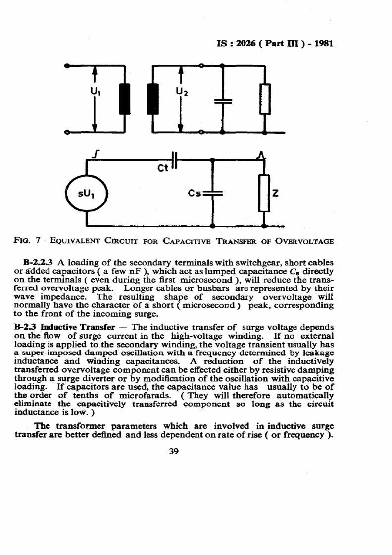
B-2.2.1 The capacitive transfer of overvoltage to a low voltage windingmay in the first approximation be described as a capacitive voltage division.The simplest equivalent circuit as seen from the low voltage winding consistsof an emf source in series with a transfer capacitance Ct ( see Fig. 7 ).
B-2.2.2 The equivalent emf is a fraction of the incoming surge on thehigh voltage side. Ct is of the order of lOWe . Cs and Ct are not well-defined quantities but dependent on the shape of the surge front. They canbe determined together by oscillographic measurements. Pre-calculation is
uncertain.
lpeci6cation for insulation coordination ( second rev& on ).
38
7/28/2019 I S 2026_3r
http://slidepdf.com/reader/full/i-s-20263r 40/45
IS:2026(PartIII)-1981
FIG. 7 EQUIVALENT IRCUIT FOR CAPACITIVBTRANSFJSRF OVFIRVOLTAGE
B-2.2.3 A loading of the secondary terminals with switchgear, short cablesor added capacitors ( a few nF ), which act as lumped capacitance C, directlyon the terminals ( even during the first microsecond ), will reduce the trans-ferred overvoltage peak. Longer cables or busbars are represented by theirwave impedance. The resulting shape of secondary overvoltage willnormally have the character of a short ( microsecond) peak, correspondingto the front of the incoming surge.
R-2.3 Inductive Transfer - The inductive transfer of surge voltage depends
on the flow of surge current in the high-voltage winding. If no externalloading is applied to the secondary winding, the voltage transient usually hasa super-imposed damped oscillation with a frequency determined by leakageinductance and winding capacitances. A reduction of the inductivelytransferred overvoltage component can be effected either by resistive dampingthrough a surge diverter or by modification of the oscillation with capacitiveloading. If capacitors are used, the capacitance value has usually to be ofthe order of tenths of microfarads. ( They will therefore automaticallyeliminate the capacitively transferred component so long as the circuitinductance is low. )
The transformer parameters which are involved in inductive surgetransfer are better defined and less dependent on rate of rise ( or frequency ).
39
7/28/2019 I S 2026_3r
http://slidepdf.com/reader/full/i-s-20263r 41/45
7/28/2019 I S 2026_3r
http://slidepdf.com/reader/full/i-s-20263r 42/45
Is:2026(Partrn) -1Y81
,c) Whether the winding is to have uniform or non-uniform insulation
and in the case of non-uniform insulation, the power frequencywithstand voltage of the neutral.
d) Whether a rated impulse withstand level is assigned to the neutral,and, in such case, the appropriate withstand voltage.
e) Whether the lightning impulse test on the line terminals shall beextended to include a chopped impulse test.
C-2. For Transformers Having a High-Voltage Winding with Urn > 300 kV :
a) Whether the transformer shall be specified and tested according toMethod I or Method 2 ( see 5.4 ).
b) If the transformer shall be specified according to Method5 a, choiceshall be made between alternative procedures for the induced over-voltage withstand test in accordance with 11.4.
C-3. It is further recommended that test connections and procedures shouldbe discussed before the time of testing5 particularly with regard to theconnection for induced overvoltage test on complicated transformerS; withnon-uniformly insulated _high-voltage winding ( see 11.3.4, Note ) and themethod to be used for impulse tests on high-power low-voltage windings andneutral terminals ( see 123 ).
41
7/28/2019 I S 2026_3r
http://slidepdf.com/reader/full/i-s-20263r 43/45
IS -: 2026 Part III ) - 1981
( Contir udfi om page 2 )
Members
SHRI S. D. CHOTRANEY
Representing
Bombay E lectric Supply and Transport Under-taking, Bombay
SHRI Y. K. PALVANKAR Alternate )DIRECTOR SUBSTATIONSSHRI P. K . DWWEDI
Central Electricity Authority, New DelhiNati$,li Thermal Power Corporation Ltd, New
SHRI A. K. GUEA UP State Electricity Board, LucknowSHRI MOINUDDIN Alternate )