WRC RESEARCH RJ3PORT No. 155
MEASUREMENTS I N MERGING FLOW
by
W. Ha l l C. Maxwell
and
Arni Snorrason
Department of C i v i l Engineering
Universi ty of I l l i n o i s a t Urbana-Champaign
Urbana, I l l i n o i s 61801
FINAL REPORT
Pro jec t No. A-103-ILL
This p r o j e c t was p a r t i a l l y supported by t h e U . S . Department o f t h e I n t e r i o r i n accordance with T i t l e I o f t h e Water Research and Development Act o f 1978,
i P.L. 95-467, Agreement No. 14-34-0001-0115.
UlJIVER3ITY OF ILLINOIS WATER RESOURCES CENTER
2535 Hydrosystems Laboratory Urbana, I l l i n o i s 61801
January 1981
Contents o f t h i s p u b l i c a t i o n do not necessar i ly ' r e f l e c t the views and p o l i c i e s o f the O f f i c e o f Water Research and Technology, U.S. Department o f the I n t e r i o r , nor does rnentlon o f t rade names o r conmerclal products c o n s t i t u t e t h e i r endorsement o r reconmendation f o r use by the U . S . Government.
ABSTRACT
Previous measurements of t h e v e l o c i t y f i e l d i n t h e v i c i n i t y of two i n t e r s e c t i n g submerged tu rbu len t j e t s provided evidence t h a t , cont rary t o t h e usual assumptions, i n t e r s e c t i n g flows may no t n e c e s s a r i l y be combined using vec tor add i t ion of v e l o c i t i e s o r momentum f l u x d e n s i t i e s .
To ga ther add i t iona l experimental evidence on t h e d e t a i l s of t h e v e l o c i t y f i e l d nea r t h e i n t e r s e c t i o n of two submerged tu rbu len t j e t s , t h i s s tudy measured time average v e l o c i t y magnitudes and d i r e c t i o n s of two perpendicular i n t e r s e c t i n g axisymmetricsubrnerged tu rbu len t incompressible a i r j e t s of approximately equal s t r eng th . Because o f t h e need t o d e t e c t r eve r se flows, a three-dimensional p i t o t - t y p e probe was used. This could sense yaw and p i t c h angles a s wel l a s v e l o c i t y magnitudes. Two s e t s o f measurements were taken. The more d e t a i l e d s e t was confined t o t h e p lane o f t h e nozzles , t h e l e s s d e t a i l e d s e t obtained c ross - sec t iona l d a t a a t four s t a t i o n s , t h r e e o f t hese being i n t h e observed r eve r se flow.
The da ta show t h a t t h e r eve r se flow spreads much more r a p i d l y perpendicular t o t h e nozzle plane than i n t h e nozzle plane, whereas t h e forward flow i s f a i r l y symmetric. , S i m i l a r i t y p r o f i l e s were found i n both t h e forward and r eve r se flows. In t h e forward flow t h e d i s t r i b u t i o n was e s s e n t i a l l y Gaussian. This was a l s o t r u e i n t h e backward flow i n t h e d i r e c t i o n normal t o t h e plane of t h e nozzles . In the p lane of t h e nozzles the backward flow p r o f i l e s were c l o s e t o s e m i - e l l i p t i c a l o r semi-c i rcu lar , depending on the s c a l e s f o r p l o t t i n g .
Maxwell, W. Hal l C . , and Arni Snorrason MEASUREMENTS I N MERGING FLOW Final r e p o r t t o t h e Off ice o f Water Research and Technology, Department of I n t e r i o r P ro jec t A-103-ILL, January 1981.
KEYWORDS: *Diffusion-flow/flow cha rac te r i s t i c s /* f low p r o f i l e s / f l u i d mechanics/* j e t s / *mixing
TABLE OF CONTENTS
ABSTRACT . . . . . . . . . . . . . . . . . . . . . . . . . . . . . . . . . . . . . . . . . . . . . . . . . . . . . . . . . LIST OF TABLES
. . . . . . . . . . . . . . . . . . . . . . . . . . LIST OF FIGURES
. . . . . . . . . . . . . . . . . . . . . . . . . . LISTOFSYMBOLS
1 . INTRODUCTION AND OBJECTIVES . . . . . . . . . . . . . . . . . . . . . . . . . . . . . 2 . VELOCITY DISTRIBUTION IN A SINGLE JET
3 . EXPERIMENTAL MEASUREMENTS IN CROSSING FLOWS . . . . . . . . . 3.1 P u r p o s e a n d S c o p e . . . . . . . . . . . . . . . . . . .
. . . . . . . . . . . . . . . . . 3.2 E x p e r i m e n t a l A p p a r a t u s
. . . . . . . . . . . . . . . 3.3 E x p e r i m e n t a l M e a s u r e m e n t s
. . . . . . . . . . . . . . . . . . . . . 3.4 D a t a R e d u c t i o n
3.5 E x p e r i m e n t a l D a t a . . . . . . . . . . . . . . . . . . . 4 . DATA ANALYSIS . . . . . . . . . . . . . . . . . . . . . . . .
. . . . . . . . . . . . . . . 5 . CONCLUSIONS AND P3COMMENDATIONS
. . . . . . . . . . . . . . . . . . . . . . 5.1 C o n c l u s i o n s
. . . . . . . . . 5.2 Recommenda t ions o n F u t u r e A p p l i c a t i o n s
. . . . . . . . . . . . . . . . . . . . . . . . . LISTOFREFERENCES
P a g e
iii
v i
v i i
v i i i
1
2
7
7
7
11
13
14
2 7
33
33
33
35
I J-
LIST OF TABLES
Table Page
1 Measured Two-dimensional Spreading Coefficients . . . . 3
2 Measured Axi-symmetrical Spreading Coefficients . . . . 5
v11
LIST OF FIGURES
Page Figure
Def in i t i on ske tch . . . . . . . . . . . . . . . . . . 8
Schematic r ep resen ta t ion of c ross ing a i r j e t a p p a r a t u s . . . . . . . . . . . . . . . . . . . . 9
Veloci ty vec to r s i n t h e p lane of t h e jets . . . . . . 15
Veloci ty i n the forward flow i n t h e p lane o f t h e n o z z l e s . . . . . . . . . . . . . . . . . . . 16
Veloci ty t r a v e r s e i n t h e backflow i n t h e p lane of t h e nozzles . . . . . . . . . . . . . . . . 17
Contours of equal v e l o c i t y i n t h e backflow a t x = 25.2 cm . . . . . . . . . . . . . . . . . . . 19
Contours of equal v e l o c i t y i n t h e backflow a t x = 25.5 cm . . . . . . . . . . . . . . . . . . . 20
Contours of equal v e l o c i t y i n t h e backflow a t x = 25.8 cm . . . . . . . . . . . . . . . . . . . 21
Contours of equal v e l o c i t y i n fbrward flow a t x = 26.2 cm . . . . . . . . . . . . . . . . . . . 2 2
Isometr ic p ro jec t ion of su r face represent ing backflow v e l o c i t i e s a t x = 25.2 cm . . . . . . . . . 2 3
Isometr ic p ro jec t ion of s u r f a c e r ep resen t ing backflow v e l o c i t i e s a t x = 25.5 cm . . . . . . . . . 2 4
I sometr ic p ro jec t ion of su r face r ep resen t ing v e l o c i t i e s a t x = 25.8 cm . . . . . . . . . . . . . . 25
Isometr ic p ro jec t ion of s u r f a c e represent ing forward v e l o c i t i t e s a t x = 26.2 cm . . . . . . . . . 26
Forward flow p r o f i l e s compared wi th Gaussian d i s t r i b u t i o n . . . . . . . . . . . . . . . . 28
Veloci ty p r o f i l e s i n t h e p lane of t h e nozzles i n the backflow . . . . . . . . . . . . . . . 2 9
Veloci ty p r o f i l e s normal t o t h e p lane of t h e nozzles i n t h e backflow . . . . . . . . . . . . . 3 1
P r o f i l e widths i n the forward and backflows . . . . . 32
LIST OF SYMBOLS
A incoming j e t nozz le , s e e Fig. 1
A. o u t l e t a r e a (per u n i t length f o r s l o t )
B incoming j e t nozzle, s e e Fig. 1
b ha l f width of v e l o c i t y p r o f i l e i n xy p lane Y
b ha l f width of v e l o c i t y p r o f i l e i n xz plane Z
C spreading c o e f f i c i e n t
j = 0 f o r p lane symmetry, = 1 f o r a x i a l symmetry
t o t a l p re s su re
p res su res sensed by l a t e r a l p o r t s
= P2 - P3
pressures sensed by upper and lower p o r t s
= P4 - P5
t r u e s t a t i c pressure
t r u e t o t a l pressure
time average ve loc i ty i n t h e x d i r e c t i o n , o r v e l o c i t y magnitude
average v e l o c i t y a t o u t l e t
average v e l o c i t y a t nozz le A o u t l e t
average v e l o c i t y a t nozz le B o u t l e t
maximum o r c e n t e r l i n e v e l o c i t y
or thogonal co-ordinate axes
ang le of p i t c h
y dev ia t ion from loca t ion of maximum v e l o c i t y
z dev ia t ion from loca t ion of maximum v e l o c i t y
angle of yaw
s tandard dev ia t ion of v e l o c i t y p r o f i l e i n xy plane
s tandard dev ia t ion of v e l o c i t y p r o f i l e i n xz p lane
2. VELOCITY DISTRIBUTION IN A SINGLE JET
The v e l o c i t y d i s t r i b u t i o n i n a submerged tu rbu len t j e t had been
considered by many i n v e s t i g a t o r s t o be adequately descri 'bed by a normal
d i s t r i b u t i o n . For both plane-symmetric and axisymmetric j e t s , t he
v e l o c i t y d i s t r i b u t i o n may be descr ibed by t h e fol lowing equat ion:
i n which u = t ime average v e l o c i t y i n t h e a x i a l , x, d i r e c t i o n ; u = average 0
v e l o c i t y a t t h e o u t l e t ; A. = o u t l e t a r e a (per u n i t l eng th f o r plane-symmetry);
C = spreading c o e f f i c i e n t ; y = a x i s normal t o x ( r a d i a l a x i s f o r a x i a l
symmetry); j = 0 f o r p lane symmetry, and j = 1 f o r a x i a l symmetry.
D i f f e ren t i n v e s t i g a t o r s have obtained d i f f e r e n t experimental
va lues f o r C, t h e spreading c o e f f i c i e n t , i n t h e case of both t h e plane-
symmetric j e t and t h e axisymmetric j e t . These r e s u l t s a r e d e a l t with i n
d e t a i l i n t h e fol lowing sec t ion .
2.2 Spreading Coef f i c i en t s f o r Plane- and Axi-Symmetric J e t s .
Table 1 summarizes spreading c o e f f i c i e n t s measured by a number of
i n v e s t i g a t o r s f o r two-dimensional t u rbu len t j e t s . The information has
been c o l l e c t e d from Refs. 1, 10 , 27 and 33. Where p o s s i b l e t h e o r i g i n a l
source of d a t a has been l i s t e d i n t h e References. The t a b l e r e f l e c t s t he
f a c t t h a t t h r e e d i f f e r e n t sources (1, 26, 33) gave t h r e e d i f f e r e n t va lues
of C from f i t t i n g F8rthmann1s data . Round-off e r r o r i n convert ing from t h e
no ta t ion of Refs. 1, 2 7 and 33 t o t h e p re sen t n o t a t i o n may account f o r p a r t
-
TABLE 1. Measured Two-dimensional Spreading Coef f i c i en t s
Experimenter
F'br t hmann
Reichard t
van d e r Hegge Zijnen
Albertson e t a l .
Reichard t
Mi l l e r & Comings
van d e r Hegge Zijnen
Nakaguchi
Olson
Bradbury
Heskestad
Knystautas
Gartshore
Heskest ad
Goldschmidt & Eskinazi
F lora & Goldschmidt
Mih & Hoopes
Jenkins & Goldschmidt
Kotsovinos
Se lec ted Average by:
Newman
Abraham
Fischer e t a l . 0.097+0.003 0.082+0.001
Year
19 34
1942
1949
1950
1951
1957
1958
1961
1962
1963
1963
1964
1965
1965
Axial C
0.098
- 0.114
0.109
- 0.093
0.092
0.107
0.100
0.100
0.098(?)
0.097
0.092
-
L a t e r a l C
0.082,0.084,0.086
0.095
0.084
0.109
0.098
0.082
0.082
0.090
0.090
0.068
0.090
0.090
0.088
0.087
0.093
of t h e d i f f e r ences . The t a b l e shows va lues ob ta ined by f i t t i n g t h e d a t a f o r
decay of t h e maximum v e l o c i t y a long t h e a x i s and va lues ob ta ined by f i t t i n g
t h e d i s t r i b u t i o n s normal t o t h e a x i s . Depending on one ' s ob j ec t i ve s ,one
may o b t a i n a "best" f i t t o e i t h e r of t h e s e d a t a sets o r , by compromising
s l i g h t l y on t h e goodness of f i t i n both cases, s e l e c t a s i n g l e spreading
c o e f f i c i e n t which a p p l i e s reasonably w e l l t o both ca se s e. g. t h e r e s u l t
ob ta ined by Albertson e t a l . (2 ) . This may then be used wi th Eq. 1. A
f u r t h e r oppor tun i ty f o r some compromise a r i s e s i n t h e s e l e c t i o n of a zero
c o r r e c t i o n o r s l i g h t s h i f t i n t h e o r i g i n of t h e co-ordinate system from t h e
phys i ca l l o c a t i o n of t h e s l o t o u t l e t .
Newman (33) concluded t h a t v a r i a t i o n s i n l a t e r a l spreading
c o e f f i c i e n t s ev ident from an examination of t h e work of e a r l i e r i n v e s t i g a t o r s
was appa ren t ly l a r g e l y due t o end e f f e c t s . E a r l i e r measurements were made
wi th low a s p e c t - r a t i o s l o t s , and i n s u f f i c i e n t c a r e was taken t o provide
f a i r i n g s on t h e end p l a t e s o r t o make them adequately l a r g e . This l e a d s
t o va lues of spreading c o e f f i c i e n t which a r e too low. H e pos tu l a t ed t h a t
v o r t i c e s forming a t t h e edge of t h e end p l a t e s induce spanwise f lows which
u s u a l l y t h i n t h e s h e a r flow. S ince t h i s problem does n o t a r i s e f o r
axisymmetric j e t s , v a r i a t i o n s i n measurements of t h e i r r a t e of growth a r e
much less. Based on a neg lec t of doub t fu l measurements Newman recommended
a l a t e r a l spreading c o e f f i c i e n t of 0.088 + 2%.
Albertson e t a l . (2) s t a t e d " . . . . c lose agreement i n t h e l i m i t e d
zone of es tab l i shment i s considered l e s s s i g n i f i c a n t than eva lua t ion of
both zones ( a s i n t h e two-dimensional case) i n terms of t h e same c o e f f i c i e n t . . . . ' I
Abraham (1) s e l e c t e d average va lues of 0.101 f o r a x i a l decay and
0.100 f o r l a t e r a l spreading a t l a r g e d i s t a n c e s from t h e o u t l e t i n h i s
TABLE 2. Measured h i - symmet r i ca l Spreading Coef f i c i en t s
Experimenter
Triipel
Betz
Ruden
Reichardt
Corrs in
Corrs in and Uberoi
Hinze and v. d. Hegge Zijnen
Keagy and Weller
Keagy, Weller, Reed & Reid
Alber t son ,Dai , J ensen& Rouse
Becher
Corrs in and Uberoi
Reichardt
Taylor , Grirnrnett, &Comings
~ l e x a n d e r , Baron & Comings
F o r s t a l l and Gaylord
Poreh and Cermak
Ricou and Spalding
Rosenweig, H o t t e l b Williams
Johannesen
Kizer
Wilson and Danckwerts
5
Year
1915
1923
1933
1942
1943
1949
1949
1949
1949
1950
1950
1950
1951
1951
1953
1955
1959
1961
1961
1962
1963
1964
1967
0.075+0.006
Average L a t e r a l C
0.072
0.081
0.076+0.002
Axia l C
- -
0.078
- -
0.076
0.078
- -
0.086
0.081
0.077
- -
0.076
0.075
0.078
0.065
- - - - - -
Average + s t . dev.
Se lec ted Average by:
Newman
Abraham
F i sche r e t a l .
L a t e r a l C
0.079
0.075
0.073, 0.076
0.072
0.071
0.072
0.071
0.075
0.070
0.075
0.081
- 0.081, 0.092
0.072
0.074
0.075
0.076, 0.078
0.071
0.081
0.076
0.073
0.070
0.085, 0.081
0.064, 0.071 pp
Year
1961
1963
19 79
0.077+0.005
Average Axial C
- 0.081
0.081+0.001
study. H e remarked t h a t t h e d a t a of Alber t son e t a l . i n d i c a t e t h a t t h e
l a t e r a l spreading c o e f f i c i e n t a c t u a l l y t ends t o i n c r e a s e wi th i nc reas ing
d i s t a n c e from t h e o u t l e t . H e i n d i c a t e d t h a t o t h e r experimental work
showed s i m i l a r t r e n d s , which agrees wi th obse rva t ions t h a t l a t e r a l d i s t r i -
bu t ions of t u r b u l e n t s t r e s s e s i n axisymmetric j e t s (7) and i n two-
dimensional jets (31) do no t e x h i b i t s i m i l a r i t y f o r d i s t a n c e l e s s than
40 diameters o r 40 s l o t h e i g h t s downstream from t h e o u t l e t .
Kotsovinos (27) a l s o advanced t h e hypothes i s t h a t t h e b a s i c
reason f o r v a r i a t i o n s i n spreading c o e f f i c i e n t s f o r p lane t u r b u l e n t jets
is t h a t growth is not exac t ly l i n e a r on a l a r g e s ca l e . Data from s e v e r a l
sources i n d i c a t e d t h a t t h e j e t width is a 'weak' non- l inear f u n c t i o n of x.
No explana t ion was advanced f o r t h e observed behavior .
F i s che r e t a l . (10) summarized va lues of l a t e r a l and a x i a l
spreading c o e f f i c i e n t s bu t d i d n o t d e t a i l t h e o r i g i n a l sources incorpora ted
i n t h e averages.
Clear ly , then , t h e r e i s no consensus on " c o r r e c t " va lues f o r
e i t h e r a x i a l o r l a t e r a l c o e f f i c i e n t s f o r two-dimensional jets.
Table 2 summarizes a x i a l and l a t e r a l spreading c o e f f i c i e n t s f o r
axisymmetr ical jets, aga in taken from Refs. 1, 10 , and 33. I n some c a s e s
where two v a l u e s a r e l i s t e d f o r t h e same t e s t , e.g. Ruden, 1933, t h e t a b l e
r e f l e c t s t h e f a c t t h a t Abraham (1) and F ischer e t a l . (10) ob ta ined
d i f f e r e n t v a l u e s of C from f i t t i n g t h e da t a . The d i f f e r e n c e aga in a l s o
i nc ludes e f f e c t s of round-off e r r o r when conver t ing from t h e n o t a t i o n used
by Abraham and by F ischer e t a l . t o t h e n o t a t i o n used h e r e i n . Table 2
i l l u s t r a t e s t h a t t h e r e is a l s o no consensus on "cor rec t" va lues of a x i a l
o r l a t e r a l c o e f f i c i e n t s f o r axi-symmetrical j e t s .
3. EmERIMENTAL MEASUREMENTS I N CROSSING FLOWS
3.1 Purpose and Scope
Measurements of v e l o c i t y time average magnitude and d i r e c t i o n
were aimed a t d e t a i l e d mapping of t h e v e l o c i t y f i e l d i n t h e v i c i n i t y of two
i n t e r s e c t i n g incompressible a i r j e t f lows. I n p a r t i c u l a r , t h e r e was an
i n t e r e s t i n t h e three-dimensional cha rac te r of t h e r e s u l t i n g j e t - l i k e
flows. Figure 1 shows a d e f i n i t i o n ske tch of the va r ious elements of t h e
flow p a t t e r n . Measurements were made holding a a t 90° and the quot ien t
u /ub i n t h e narrow range 1.015 i- 0.001. The discharge through tubes a
A and B was he ld cons tant by monitoring t h e pressure a t and ac ross the
o r i f i c e meters i n t h e i r supply l i n e s (Fig. 2) . The co-ordinate system was
a l igned with t h e x-axis approximately p a r a l l e l t o CD, t h e a x i s of maximum
v e l o c i t y f o r t h e r e s u l t a n t flow, and t h e y-axis p a r a l l e l t o a l i n e through
t h e tube o u t l e t s .
3.2 Experimental Apparatus
The apparatus used t o s tudy the v e l o c i t y d i s t r i b u t i o n i n t h e flow
f i e l d c rea t ed by two cross ing a i r j e t s is i l l u s t r a t e d i n F ig . 2. Two
i d e n t i c a l 3/16 in . (0.475 cm) i n t e r n a l diameter copper tubes were used
a s nozzles and were mounted perpendicular t o each o t h e r on a h o r i z o n t a l
board. Each copper tube was connected t o a 1 112 i n . (3.8 cm) diameter
pipe by means of tygon tubes. I n order t o maintain and monitor cons tant
pressure , a pressure r egu la to r and gauge were i n s t a l l e d i n t h e a i r supply
upstream from the 1 112-in. pipe. A d i f f e r e n t i a l water manometer was used
t o measure t h e p res su re drop ac ross t h e o r i f i c e . The p res su re on t h e
upstream s i d e of t h e p l a t e was measured using a mercury manometer. The
ho r i zon ta l board was l e v e l l e d on a t a b l e top,and a probe t r a v e r s i n g mechanism
LOCATION OF OUTLET
- D
CENTERS
! I I TUBE x , c m y , f t z , i n
A 23.68 0.956 18.77
B 23.68 1.119 18.77
Fig. 1 Defin i t ion sketch
3/16" x 1 1 / 2 " ORFICE METER -', TYGON TUBE
a 1 - I 1 1 1 / 2 " I D P I P E
NEEDLE VALVE
\ - PRESSURE GAUGE
PRESSURE REGULATOR
3/16" I D COPPER
TYGON TUBE
TUBE
Fig. 2 - Schematic representation of crossing air j et apparatus
was mounted on a r i g i d framework independent ly mounted on t h e f l o o r .
Time average v e l o c i t y magnitudes and d i r e c t i o n s were measured
us ing a United Sensor and Control Corporat ion Type DC three-dimensional
d i r e c t i o n a l probe. This had a s ens ing head diameter of 1/8-in. (0.318 cm)
and a l e n g t h of 36-in. (91.4 cm) . It was mounted on a United 'Sensor and
Control Corporat ion manual t r a v e r s e u n i t . This has b 0 t h . a l i n e a r v e r n i e r
t r a v e r s i n g s c a l e f o r d i s t a n c e read ings and a r o t a r y v e r n i e r s c a l e f o r
angle of yaw readings. The read ings p r e c i s i o n on t h e l i n e a r s c a l e was
0.01 i n . (0.025 cm) and 0 . 1 degrees on t h e angu la r v e r n i e r s c a l e .
The manual t r a v e r s e u n i t was mounted on a s t u r d y h o r i z o n t a l
c a r r i a g e running on a l a r g e r h o r i z o n t a l c a r r i a g e . This i n t u r n r a n
pe rpend icu l a r ly on h o r i z o n t a l r a i l s incorpora ted i n a heavy s t e e l frame
and was moved us ing a p o i n t gage set h o r i z o n t a l l y . The v e l o c i t y probe,
thus mounted, could be moved i n t h r e e mutual ly or thogonal d i r e c t i o n s and
r o t a t e d wi thout a l t e r i n g t h e l o c a t i o n of t h e sens ing head. Co-ordinates
w e r e recorded t o 0.01 i n . (0.025 cm), 0.001 f t (0.030 cm) and 0 .1 cm
(0.039 i n . ) , us ing t h e manual t r a v e r s e , po in t gage read ing and main
c a r r i a g e l o c a t i o n s c a l e s r e spec t ive ly .
The three-dimensional d i r e c t i o n a l probe measures t h e yaw and
p i t c h ang le of t h e v e l o c i t y vec to r a s w e l l a s t o t a l and s t a t i c p r e s su re s .
Five sens ing p o r t s a r e l oca t ed on t h e t i p of t h e probe. The c e n t r a l l y
l o c a t e d p o r t senses t h e t o t a l p r e s su re P The two l a t e r a l p o r t s sense 1'
p re s su re s P and P The probe is r o t a t e d us ing t h e manual t r a v e r s e u n i t 2 3'
u n t i l P = P a s i n d i c a t e d on a d i f f e r e n t i a l manometer. The v e r n i e r on 2 3
t h e c i r c u l a r s c a l e of t h e manual t r a v e r s e u n i t then i n d i c a t e s t h e yaw angle .
With t h e probe a l igned along t h e d i r e c t i o n f o r which P = P -P = 0 t h e 23 2 3
d i f f e r e n t i a l p re s su re P = P -P sensed by t h e two p o r t s above and below 45 4 5
t h e t o t a l p re s su re p o r t is read on a d i f f e r e n t i a l manometer. The
c a l i b r a t i o n curve f o r t h e probe can then be used t o determine t h e angle of
p i t ch . This is a func t ion of P /P i n which P = pl-112 (P2 + P3). 45 12' 12
For any p a r t i c u l a r p i t c h angle , B , t h e c a l i b r a t i o n curve of (Pt-P )/.P s 12
may be used t o determine t h e v e l o c i t y . Pt = t r u e t o t a l p re s su re and
P = t r u e s t a t i c pressure . The f l u i d v e l o c i t y is S
= [2(Pt - Ps)/pI 112 (2)
The d i f f e r e n t i a l manometers f l u i d was Meriam 827 Red O i l which
has a s p e c i f i c g r a v i t y of 0.827. The P12 manometer was t i l t e d a t 45'; t h e
'23 and P manometerswere t i l t e d a t 20.5'. For d a t a r educ t ion t h e
45
c a l i b r a t i o n curve f o r p i t c h ang le was approximated by two l i n e a r func t ions ,
one f o r p i t c h ang le s i n t h e range + 10' w i th maximum e r r o r of lo, t h e
o t h e r f o r 2 40' wi th maximum e r r o r of + 2.5'. The p i t c h ang le measurements
wereunreliablewhenvelocities, a n d h e n c e p were low. A l o w e r l i m i t 12'
of 0.8 l b s per square f o o t was t h e r e f o r e s e t on measurements of P12. A
good approximation t o t h e c a l i b r a t i o n curve f o r p i t c h ang le s i n t h e
range + 10' i s t h e cons tan t va lue 0.87 f o r (P -P )/p12. Since t h e v a s t t s
ma jo r i ty of r e l i a b l e readings f e l l w i th in t h i s range t h i s cons tan t va lue
was used f o r d a t a reduct ion .
3 .3 Experimental Measurements
For each measurement s e t t h e atmospheric temperature and p re s su re
were recorded. For t h e mapping of t h e v e l o c i t y v e c t o r f i e l d i n t h e p lane
of t h e nozz les ( z = 18.77 cm) t r a v e r s e s were made a t constant va lues of x ,
wi th y being var ied . The z - se t t i ng w a s found by t r a v e r s i n g t h e p i t o t u n t i l
maximum v e l o c i t y was found. Traverses were repea ted a t x i n t e r v a l s ranging
from 0 .1 cm up t o 0.5 cm, s o a s t o cover t h e incoming j e t s , t h e forward
j e t and t h e back flow j e t . The va lues of P 12 ' Pt , yaw angle and P a s
45 ' w e l l a s t h e coord ina tes (x, y , z ) of t h e probe t i p were recorded a t each
po in t of t h e t r a v e r s e . I n t h e zone nea r t h e s t agna t ion p o i n t , v e l o c i t i e s i n
t h e back f low j e t were very smal l and t h e r e was i n t e r f e r e n c e between t h e
probe and t h e incoming j e t s . The back flow j e t measurements were t h e r e f o r e
conducted wi th cons t an t yaw angle . The yaw ang le was s e t by moving back
i n t o a r eg ion of h ighe r v e l o c i t y back flow. The a p p l i c a b i l i t y of ho ld ing
t h e yaw a n g l e cons tan t i n t h e e n t i r e back flow region was checked from
t i m e t o t i m e where t h e back flow v e l o c i t y was s u f f i c i e n t l y h igh t o permit
it, and proved t o be adequate. S imi l a r d i f f i c u l t i e s were found near t h e
edges of t h e incoming j e t s ad jacent t o t h e backflow j e t and were again
reso lved by s e t t i n g t h e yaw ang le t o i t s va lue i n t h e ad j acen t reg ion of
h ighe r incoming v e l o c i t y . I n a l l o t h e r p o r t i o n s of t h e f low f i e l d t h e
p i t o t was set a t t h e yaw ang le determined by P = 0. 2 3
Because adjustment of t h e yaw ang le was very time-consuming
and considerably more d a t a p o i n t s had t o be c o l l e c t e d f o r mapping of t h e
c ros s - sec t iona l v e l o c i t y f i e l d , t h e yaw ang le was s e t a t a cons t an t va lue
determined i n t h e reg ion of maximum v e l o c i t y f o r t h e forward j e t . Traverses
were made a t cons t an t yaw angle and cons t an t x. For each c ross -sec t ion
t r a v e r s e s were made i n t h e y d i r e c t i o n f o r va r ious va lues of z . Three
c r o s s s e c t i o n s were measured f o r t h e back flow j e t and one f o r t h e
forward j e t . The va lues of P 12' Pt ' P45 and x , y and z were recorded f o r
each p o i n t whi le holding t h e yaw ang le cons tan t .
3.4 Data Reduction
Computer programs were developed t o analyze and present t h e da t a .
Three s e t s of programs were u t i l i z e d : one f o r handl ing raw d a t a ; one f o r
g raph ica l p re sen ta t ion of t h e v e l o c i t y v e c t o r f i e l d i n t h e p lane of t h e
nozz les ; and one f o r g raph ica l p re sen ta t ion of t h e c ros s - sec t iona l da t a .
The program f o r handl ing of raw da ta c a l c u l a t e d p i t c h ang le s
and v e l o c i t y p re s su re c o e f f i c i e n t s by l i n e a r i n t e r p o l a t i o n of t h e
c a l i b r a t i o n curves f o r t he probe. The o u t l e t average v e l o c i t i e s were
ca l cu la t ed using the c a l i b r a t i o n s f o r t h e o r i f i c e meters used i n t h e
supply l i n e s t o determine t h e a i r discharge.
The second program non-dimensionalized t h e raw d a t a and
p l o t t e d t h e v a r i a t i o n of t h e v e l o c i t y , yaw angle , 8 , and p i t c h ang le ,
6 % f o r each t r a v e r s e . A subrout ine was used t o p l o t t h e vec to r f i e l d ,
showing t h e ang le of yaw and t h e length of t h e v e l o c i t y vec to r . The
i n t e r f a c e between t h e back flow j e t and t h e incoming j e t s A and B was no t
w e l l def ined. The most probable explana t ion i s t h a t t h e incoming j e t s
i n t e r f e r e wi th t h e p i t o t tube when t h e backflow j e t i s measured and
the backflow j e t i n t e r f e r e s wi th t h e p i t o t tube when t h e incoming j e t s
a r e measured. Two s e t s of p l o t s were prepared, one g iv ing t h e forward
v e l o c i t i e s readings p r i o r i t y , t h e o t h e r g iv ing p r i o r i t y t o t h e backward
v e l o c i t i e s . The zone where t h e p l o t s d i sag ree i n d i c a t e s t h e reg ion of
i n t e r f e r e n c e .
The program f o r t h e c ros s - sec t iona l d a t a was used t o p l o t contour
o r i s o v e l o c i t y p l o t s and t o i l l u s t r a t e t h r e e dimensional s u r f a c e s viewed
from d i f f e r e n t vantage po in t s .
3.5 Experimental Data
F i g u r e 3 shows a p l o t of t h e v e l o c i t y v e c t o r f i e l d i n t h e p l ane
of t h e j e t nozz l e s . Th i s p l o t is a composite of t h e p l o t s de sc r i bed i n t h e
last s e c t i o n . The p l o t g iv ing backward v e l o c i t i e s p r i o r i t y was l a i d over
t h e p l o t g i v i n g t h e forward v e l o c i t i e s p r i o r i t y . The r e g i o n of disagreement
between t h e s e two is hatched i n F igu re 3, which is b a s i c a l l y t h e backward
p r i o r i t y p l o t . There may b e some c o r r e l a t i o n between t h e f a c t t h a t more
c o n f l i c t i s observed on one s i d e of t h e flow p a t t e r n and t h e f a c t t h a t t h e
probe always p rogressed i n t o t h e f low f i e l d from t h a t s i d e . Note a l s o t h a t
t h e l i n e a r s c a l e is i n d i c a t e d a t t h e t o p of t h e f i g u r e . Some of t h e
measurements were t aken a t a l a t e r t i m e than o the r s , and i t w a s no ted
t h a t t h e maxima of t h e later and earlier p r o f i l e s d i d n o t q u i t e l i n e
up. Th i s w a s a t t r i b u t e d t o s l o p i n t h e c a r r i a g e r a i l system, and an
i n d i c a t i o n of i t s o r d e r of magnitude is no ted on t h e f i g u r e . T h i s problem
d i d no t p r e s e n t i t s e l f dur ing any con t inuous set of measurements and on ly
became e v i d e n t n e a r t h e end of t h e exper imenta l program when some
measurements were made t o f i l l i n gaps i n t h e v e c t o r f i e l d p l o t . It would
appear t o be r ea sonab l e t o s h i f t t h e p r o f i l e s t o a l i g n t h e maxima; however \
t h e d a t a a r e p r e sen t ed a s recorded . F i g u r e 3 is u s e f u l i n a s s e s s i n g t h e
o v e r a l l c h a r a c t e r of t h e flow. However t h e d e t a i l e d t r a v e r s e s upon which
it is based a r e more u s e f u l i n a n a l y s i n g t h e e x i s t e n c e o r no t of
s i m i l a r i t y p r o f i l e s w i t h i n t h e f low and t h e i r d e t a i l e d c h a r a c t e r . Two
c r o s s - s e c t i o n a l l o c a t i o n s are f l agged on Fig. 3 a t x v a l u e s of 25.4 cm and
26.0 cm. The d e t a i l e d t r a v e r s e s f o r t h e s e two l o c a t i o n s a r e p r e sen t ed i n
F ig s . 4 and 5 . Figure 4 shows t h e v a r i a t i o n of v e l o c i t y magnitude, yaw
MAXIMUM VELOCITY 2 2 9 . 3 f p s OUTLES AT X = 2 3 . 6 8 cm
SHIFT DUE TO CARRIAGE SLOP
REGION OF CONFLICTING DATA
TRAVERSE STARTED FROM THIS SIDE
F i g . 3. V e l o c i t y v e c t o r s i n t h e p l a n e o f t h e j e t s .
THE REFERENCE VELOCITY I F 229.3 FBS THE REFERENCE ANGLE I S 180' OUTLET CENTERS AT X a 23.68 CM, Z = 1.564 FT
- YAW ANGLE, 0 +-+ -At
A.
'n 4--+ +-- ' ,,A'-. -3-
- j++ -.+ - +-A jh+-?c -
\
I - -+ -Y -F- ,/ \ . ~ x -- +
\ ./,/ '/ / PITCH ANGLE, B
Fig. 4. Veloc i ty i n the forward f low i n the plane of the nozz les .
5 - . 2 5 +
I : M , E N 1 :S - . 5 * I I
0 ' N , : L - - 7 5 -.- E
I s
S Iv I I I -1 .
-- ---- - -- - - -- - - - -- - - - -
THE X - L g C IS 26.0 CM 1 I T H E Z-LCiC I S 1 . 5 6 4 ~ ~ ! TWE 3,I"E I S 3 i 1 1 9 G 3 i
I
I I t -- 1- - ----+---.-I 0 . 1 . 2 . 3 . 4 .
- 5 1. 5 2 . 5 3 . 5
r-- .i-. . - . - . ,- " .- . .-.----.--...--z.-----.u.-.--.m....
: J . . . / C.
-r ! .THE REFERENCE VELOCITY I S 229.3 FPS
I :.- j r- / , J
THE REFERENCE ANGLE I S 180' , C 1 OUTLET CENTERS AT X - 23.68 CM, Z = 1.564 FT
;I , r i 7-
I j I
/ I T
/ f-:
i ;r . 5 -!- i
> -? > , 1
i I I i A ---6 VELOCITY
4 f
L' .+ -{ ',
-. 2
I i
.1 PITCH ANGLE, B a A.
"A
't" - i3 2 pi t:' C T 13 N (NOZZLE DIMTERS)
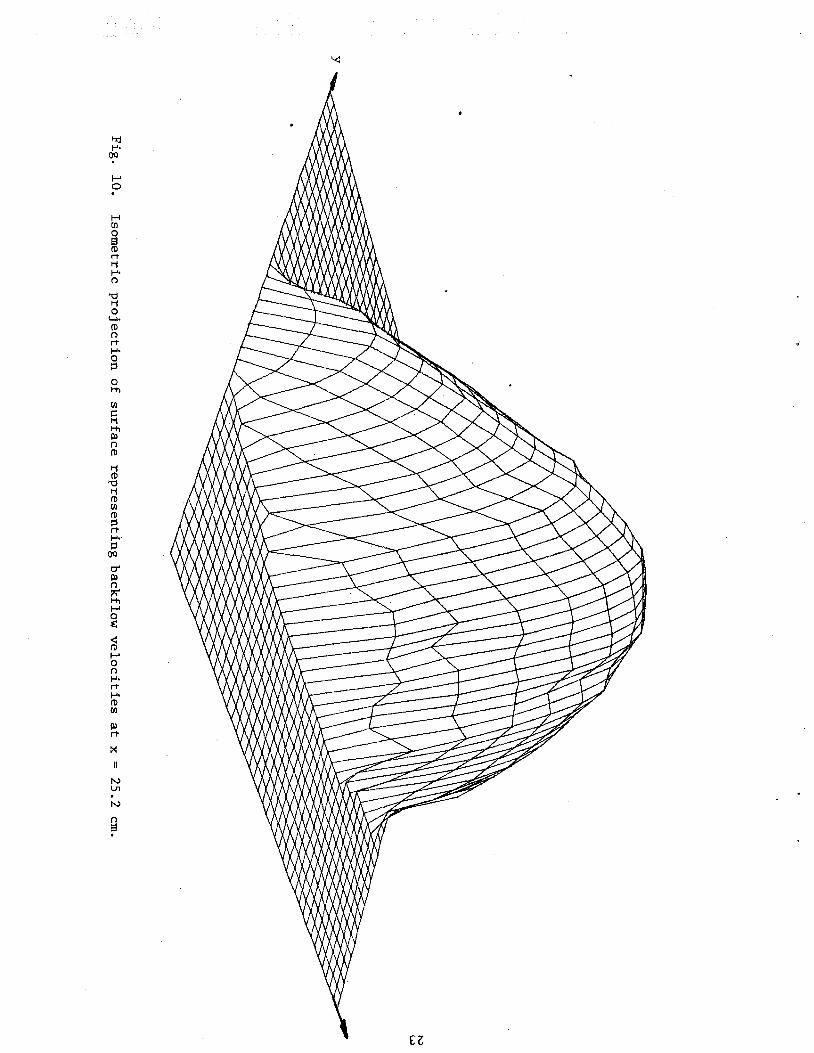
Fig. 5. Velocity traverse in the backflow in the plane of the nozzles.
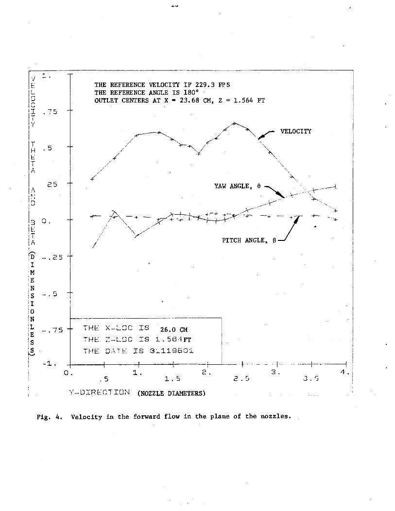
a n g l e and p i t c h a n g l e i n t h e forward f low r e g i o n as t h e two incoming jets
merge. I ts g e n e r a l form sugges t s t h e con junc t i on of two e s s e n t i a l l y
Gaussian p r o f i l e s . F igu re 5, on t h e o t h e r hand, shows t h e same parameters
i n t h e reg ion of backflow. C l e a r l y t h e v e l o c i t y p r o f i l e i n t h a t reg ion i s
non-Gaussian i n c h a r a c t e r .
F igs . 6 through 9 show contours of equa l v e l o c i t y a t f o u r
l o c a t i o n s i n t h e f low f i e l d . Figs . 6 through 8 are l o c a t e d i n t h e r eg ion
of backflow. These i l l u s t r a t e t h a t t h e backflow sp reads much more r a p i d l y
i n t h e z - d i r e c t i o n than i n t h e y -d i r ec t i on . Fig. 9 is i n t h e forward
flow. Note t h a t it i s p l o t t e d t o a d i f f e r e n t l i n e a r s c a l e t h a n t h e t h r e e
p reced ing f i g u r e s . F ig s . 1 0 through 1 3 show t h r e e dimensional s u r f a c e
p r o j e c t i o n s of t h e same d a t a viewed from a p o i n t on a l i n e p a r a l l e l t o
t h e x-axis , w i th t h e l i n e of s i g h t depressed 15' towards t h e yz p l ane and
a t an a n g l e of 45' t o bo th t h e x and y d i r e c t i o n s .
I n o r d e r t o c r e a t e F ig s . 6 through 1 3 m a t r i c e s were formed t o
ho ld d a t a from t r a v e r s e s t aken a t i n t e r v a l s of z . S ince t h e z i n t e r v a l s
were less i n some f low r eg ions t han o t h e r s , i n t e r m e d i a t e p r o f i l e s were
c r e a t e d by l i n e a r i n t e r p o l a t i o n where d a t a d i d n o t e x i s t . Then, t o
c o r r e c t f o r t h a t f a c t t h a t u n i t s and i n t e r v a l s of measurements were
d i f f e r e n t i n t h e y and z d i r e c t i o n s , a new m a t r i x was c r e a t e d u s ing a f o u r
p o i n t i n t e r p o l a t i o n scheme. This l a t te r ma t r i x i s t h a t upon which t h e
p l o t s a r e based. The e lements of t h e ma t r i x are t h u s n o t n e c e s s a r i l y
p h y s i c a l d a t a , b u t a r t i f i c i a l d a t a c r e a t e d by i n t e r p o l a t i o n .
r I-'.
OP Y
n 0
R 0 z V1
0 M
n, 9
E . P
9 . P 0 0 I-'.
.c" G- l-t 3 n,
'3 PI D 7; M P
2 s X (I
P\) Cn
Cn
p
!- 7 y (interval 0.01 in.)
4. DATA ANALYSIS
I n o rde r t o develop assumptions as t o t h e cha rac te r of s i m i l a r i t y
p r o f i l e s i n t h e flow, which could b e used as t h e b a s i s f o r development of
a so lu t ion , t h e forward and backward flow p r o f i l e s were examined f o r
s i m i l a r i t y .
Figure 14 shows t h e p r o f i l e s measured i n t h e forward flow
compared wi th a normal d i s t r i b u t i o n . Clear ly they a r e e s s e n t i a l l y
Gaussian i n charac ter . Figure 15, on t h e o t h e r hand,shows t h e v e l o c i t y
p r o f i l e s i n t h e plane of t h e nozzle i n t h e back flow. Since t h e r e is
r e v e r s a l of flow a t t h e edge of t h e j e t , t h e j e t width f o r zero v e l o c i t y
may be c l e a r l y defined. However, s i n c e i n most circumstances such a
d i s t i n c t p r o f i l e edge does not e x i s t , i t has become customary t o work wi th
t h e half-width of t h e veloc2ty p ro f i l e , i . e . t h e width of t he p r o f i l e
when t h e v e l o c i t y is equal t o ha l f t h e maximum value . I n t h i s case
b = half-width i n t h e xy plane and bZ = half-width i n t h e xz plane. Y
Because t h e r e is a d i s t i n c t edge t o t h e j e t a Gaussian p r o f i l e would
not be appropr ia te . F igure 15 has p l o t t e d on i t a cubic curve and
an e l l i p s e a s poss ib l e simple funct2ons. The e l l i p s e f i t s t h e d a t a we l l
i n t h e reg ion of higher v e l o c i t i e s and l e s s we l l i n the region where
v e l o c i t i e s a r e l e s s r e l i a b l e . It i s of course poss ib l e t o a l t e r t h e absc i s sa
s c a l e t o make t h e dimensionless base width of t h e p r o f i l e equal t o one,
i n which case t h e semi-e l l ipse becomes a semi-circle. The equat ion f o r
t h e e l l i p s e i s
The cubic equat ion is given by
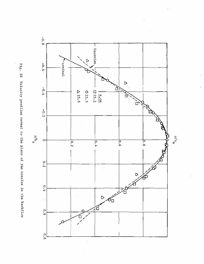
Figure 16 shows t h e corresponding p l o t f o r t h e v e r t i c a l d i s t r i b u t i o n of
v e l o c i t i e s i n t h e back flow. I n t h i s case t h e d a t a is w e l l f i t by a
simple cos ine funct ion
2 8 Az u/um = cos (- -)
3 b Z
Since t h e r e is no c l e a r r e v e r s a l of d i r e c t i o n a t t h e upper and lower edges
of t h i s p r o f i l e i t may a l s o be q u i t e w e l l f i t by the Gaussian d i s t r i b u t i o n
u/u, = exp [-2.77 ( ~ z l b ~ ) ' ]
Thus, t h e p r o f i l e i n t h e reverse flow may be represented by a combination
of Eq. 3 o r 4 w i th Eq. 5 o r 6.
Figure 17 shows t h e measured va lues of b and bZ i n t h e r eve r se Y
flow, and t h e observed va lues of a i n t h e forward flow.
The s t agna t ion poin t obtained by l i n e a r i n t e r p o l a t i o n from t h e
p r o f i l e s shown on Fig. 3, i s indica ted on Fig. 17 f o r re ference . The
da ta suggests t h a t , a f t e r some i n i t i a l d i s t ance back from t h e s t agna t ion
poin t , t h e r e i s n e g l i g i b l e spreading i n t h e plane of t h e nozzles and
approximately l i n e a r spreading normal t o t h i s plane.
44
5. CONCLUSIONS AND RECOMMENDATIONS
5.1. Conclusions
I n t e r s e c t i n g flow may no t n e c e s s a r i l y be combined us ing vec to r add i t i on
of v e l o c i t i e s o r momentum f l u x d e n s i t i e s . When two perpendicular i n t e r s e c t i n g
axisymmetric submerged tu rbu len t j e t flows of approximately equal s t r e n g t h
combine, a reg ion of backflow i s observed. The backflow spreads much more r a -
p i d l y i n t h e d i r e c t i o n perpendicular t o t h e p l ane o f t h e nozz les than i t does
i n t h e p lane of t h e nozz les . In t h e reg ion of forward flow t h e p r o f i l e s were
e s s e n t i a l l y Gaussian. In t h e reg ion of backflow t h e p r o f i l e s were approximately
e l l i p t i c o r cubic i n t h e p lane of t h e nozz le , and approximately Gaussian o r
c o s i n a l normal t o t h i s p lane . A f t e r some i n i t i a l d i s t a n c e back from t h e s t a g -
n a t i o n p o i n t observed i n t h e flow, spreading i n t h e backflow i n t h e p lane of t h e
nozz les appeared t o be n e g l i g i b l e and approximately l i n e a r normal t o t h i s p lane .
Attempts t o develop an a n a l y t i c s o l u t i o n f o r t h e flow f i e l d have so f a r proved
unsuccessfu l . The s i m i l a r i t y p r o f i l e s may, however, provide t h e b a s i s f o r
u s e f u l assumptions i n developing such a s o l u t i o n . Because o f t h e l i m i t e d amount
of d a t a which could be c o l l e c t e d i n t h i s i n v e s t i g a t i o n , it would be unwise t o
at tempt t o draw any genera l conclusions about t h e magnitudes of empir ica l
c o e f f i c i e n t s used t o f i t mathematical formulat ions t o t h e observed d a t a .
5 .2 . Recommendations on Future Appl ica t ions
The work descr ibed i n t h i s r e p o r t r ep re sen t s an i n i t i a l i n v e s t i g a t i o n
of a phenomenon t h a t , when more f u l l y understood, can lead t o an improvement
i n t h e q u a l i t y of p r e d i c t i v e computational models f o r t h e flow f i e l d s involv ing
zones of chemical, sedimentary o r thermal ly a l t e r e d d ischarges i n t o moving
c u r r e n t s . Present methods a r e gene ra l ly based on t h e no t ion t h a t an accu ra t e
gene ra l d e s c r i p t i o n of t h e flow f i e l d may r e s u l t from v e c t o r combinations of
v e l o c i t i e s o r momentum f luxes on an elementary l e v e l . Such models then have t o
be modified t o t a k e i n t o account wake e f f e c t s by t h e in t roduc t ion of drag coef-
f i c i e n t s . Extension of t h e p re sen t work which might l ead t o improved modeling
of t h e elementary process used t o syn thes i ze t h e o v e r a l l f low p a t t e r n would inc lude
numerical a n a l y t i c i n v e s t i g a t i o n of t h e p re s su re f i e l d t h a t develops when a s imple
j e t i s d i r e c t e d a t an angle toward a f l a t su r f ace , and t h e ex tens ion of t h i s
i n v e s t i g a t i o n t o t h e p re s su re f i e l d wi th in t h e flow c rea t ed by two merging s t reams.
F i n a l l y , a t h e o r e t i c a l b a s i s should be sought t o j u s t i f y t h e combination of small
elements of l a r g e flow f i e l d s , t a k i n g i n t o account backflows (which may be over-
r idden by t h e forward flow i n a proximate element). This would provide t h e
p o s s i b i l i t y of p r e d i c t i n g a flow p a t t e r n involving backflows i n some reg ions
without t h e n e c e s s i t y of in t roducing a r t i f i c i a l concepts such as drag c o e f f i c i e n t s
accounting f o r t h e blockage e f f e c t of t h e i n j e c t e d flow.
LIST OF REFERENCES
1.. Abraham, G . , " J e t D i f f u s i o n i n S tagnan t Ambient F l u i d , " D e l f t Hydrau l ics Labora to ry P u b l i c a t i o n s , No. 29, J u l y , 1963.
2 . A l b e r t s o n , M. L. , Dia, Y. B . , J ensen , R. A . , and Rouse, H . , " D i f f u s i o n o f Submerged J e t s , " T r a n s a c t i o n s , ASCE, Vol. 115, Paper No. 2409, 1950 pp. 639-697.
3. Alexander, L. G . , Baron, T. , and Comings, E. W . , " T r a n s p o r t a t i o n of Momentum, Mass, and Heat i n Turbu len t Jets," B u l l e t i n S e r i e s No. 413, U n i v e r s i t y o f I l l i n o i s Engineer ing Experiment S t a t i o n , Urbana, I l l . , May, 1953.
4. Becher, P . , " L u f t s t r a h l e n a u s Ventilations-tjffnungen, Gesundhei ts i n g e n i e u r , No. 9 /10, Mai, 1950, pp. 139-145.
5. Be tz , A . , "Versuche iiber d i e Ausbrei tung e i n e s f r e i e n S t r a h l e s , " Ergebn isse d e r Aerodynamischen V e r s u c h s a n s t a l t zu Ggt t ingen , 11, 1923. pp. 69-73.
6. Bradbury, L.J .S . , "An I n v e s t i g a t i o n I n t o t h e S t r u c t u r e of a Turbu len t P l a n e Jet," Ph.D. T h e s i s , U n i v e r s i t y of London, 1963.
7. C o r r s i n , S . , " I n v e s t i g a t i o n o f Flow i n a n A x i a l l y Symmetrical J e t of A i r , " N.A.C.A. Wartime Repor t s , W-94, Dec., 1943.
8. C o r r s i n , S . , and Uberoi, M. S . , " F u r t h e r Experiments on t h e Flow and Heat T r a n s f e r i n Heated Turbu len t A i r J e t , " N.A.C.A. T e c h n i c a l Notes , N 1865, A p r i l , 1949.
9. C o r r s i n , S. , and Uberoi, M. S., " F u r t h e r Experiments on t h e Flow and Heat T r a n s f e r i n a Heated Turbu len t A i r Jet . , N.A.C.A. Repor t s , No. 998, 1950.
10. F i s c h e r , H. B . , L i s t , E. J . , Koh, R .C .Y . , Imberger , J . , and Brooks, N .H . , Mixing i n I n l a n d and C o a s t a l Waters, Academic P r e s s , New York, N . Y . ,
1979.
11. F l o r a , J . , and Goldschmidt, V. , " V i r t u a l O r i g i n s o f a F r e e P l a n e Turbu len t Jet," American I n s t i t u t e of Aeronau t ics and A s t r o n a u t i c s J o u r n a l , Vol. 7, 1969, pp. 2344-2346.
12. F o r s t a l l , W . , and Gaylord, E. W . , "Momentum and Mass T r a n s f e r i n a Submerged Water J e t , " J o u r n a l of Appl ied Mechanics, Vol. 22, 1955, pp. 161-164.
13. Fgrthmann, E., "Turbu len t Jet Expansion," N.A.C.A. Techn ica l Memoranda, No. 789: T r a n s l a t e d from Ing. Arch., Vol. 5 , 1934, pp. 42-54.
14. G a r t s h o r e , I. S., "The Streamwise Development o f Two-Dimensional Wall Jets and Other Two-Dimensional Turbu len t Shear Flows," Ph.D. T h e s i s , Mechanical Engineer ing, McGill U n i v e r s i t y , 1965.
Goldschmidt, V. , and Eskinaz i , S. , "Two Phase Turbulent Flow i n a P l ane Jet," Jou rna l of Applied Mechanics, Vol. 33, 1966, pp. 735-747.
Hegge Zi jnen, B. G. van de r , "Measurements of t h e Ve loc i ty D i s t r i b u t i o n i n a P l a n e Turbulent Jet of A i r , " Applied S c i e n t i f i c Research, Vol. 7, Sec t ion A, 1958, pp. 256-276.
Heskestad, G . , "Two Turbulent Shear Flows," Johns Hopkins Un ive r s i t y , Mechanical Engineering Contract AF(638) -248, 1963.
Heskestad, G.,"Hot Wire Measurements i n a P l a n e Turbulent Jet," Jou rna l of Applied Mechanics, Vol. 32, 1965, pp. 721-734 (erratum, Sept. 1966, p. 710).
Hinze, J. O . , and Hegge Zi jnen, B. G. van d e r , "Transfer of Heat and Mat te r i n t h e Turbulent Mixing Zone of an Axia l ly Symmetric ~ e t , " Applied S c i e n t i f i c Research, The Hague, Sec t ion A , Vol. 1, 1949, pp. 435-461.
Jenkins , P. E . , and Goldschmidt, V. , "Mean Temperature and Veloc i ty i n a P l ane Turbulent Jet," Jou rna l of F l u i d s Engineering, Transac t ions ASME, Vol. 95, 1973, pp. 581-584.
Johannesen, N. H . , "Fur ther Resu l t s on t h e Mixing of Free Axial ly- Symmetrical J e t s of Mach Number 1.40;' Aeronaut ica l Research Council Technical Report, R and M No. 3292, 1962.
Keagy, W. R . , and Weller , A. E. , "A Study of F r e e l y Expanding Inhomogeneous J e t s , " Heat T rans fe r F lu id Mechanics I n s t i t u t e , 2nd Berkeley, C a l i f o r n i a , 1949, pp. 89-98.
Keagy, W. R . , Weller , A. E. , Reed, F. A , , and Reid, W. T. , B a t e l l e Memorial I n s t i t u t e , The Rand Corporat ion, Santa Monica, C a l i f o r n i a , Feb. , 1949.
Kizer , K. M . , "Mater ia l and Momentum Transport i n Axisymmetric Turbulent Jets of Water," American I n s t i t u t e of Chemical Engineers J o u r n a l , Vol. 9, 1963, pp. 386-390.
Knystautas , R . , "The Turbulent Jet ,From a S e r i e s of Holes i n Line," Aeronaut ica l Qua r t e r ly , Vol. 15, 1964, pp. 1-28.
Kotsovinos, N. W . , "A Study of t h e Entrainment and Turbulence i n a Plane Turbulent Jet, " W. M. Keck Laboratory Reports , KH-R-32 C a l i f o r n i a I n s t i t u t e of Technology, Pasadena, C a l i f o r n i a , 1975.
Kotsovinos, N. E . , "A Note on t h e Spreading Rate and V i r t u a l Or ig in of a P l ane Turbulent Jet," Jou rna l of F lu id Mechanics, Vol. 77, P a r t 2 , 1976, pp. 305-311.
Maxwell, W. 11. C . , and Snorrason, A . , "Measurements i n I n t e r s e c t i n g Submerged and Induced Jets," U n i v e r s i t y o f I l l i n o i s C i v i l Eng ineer ing S t u d i e s , Hydrau l ic Engineer ing Research S e r i e s , No. 34, Aug. 1979.
Maxwell, W. H. C . , "Cross ing Submerged Jets," J o u r n a l of t h e Hydrau l ics D i v i s i o n , ASCE, Vol. 105, No. HY12, Proc. P a p e r 15016,Dec. 1979, pp. 1557-1560.
Mih, W. C . , and Hoopes, J. A . , "Mean and Turbu len t V e l o c i t i e s f o r P l a n e Jet," J o u r n a l o f Hydrau l ics D i v i s i o n , ASCE, Vol. 98, 1972, pp. 1274-1294.
Miller, D. R., and Comings, E. W . , " S t a t i c P r e s s u r e D i s t r i b u t i o n i n t h e F r e e Turbu len t J e t , " J o u r n a l of F l u i d Mechanics, Vol. 3 , P a r t I, 1957, pp. 1-16.
Nakaguchi, H . , " J e t Along a Curved Wall," U n i v e r s i t y of Tokyo Research Memoranda, No. 4 , 1961.
Newman, B. G . , "Turbu len t J e t s and Wakes i n a P r e s s u r e Grad ien t , " F l u i d Mechanics o f I n t e r n a l Flow, G. Sovran, ed . , E l s e v i e r P u b l i s h i n g Company, The Nether lands , 1967, pp. 170-209.
Olson, R. E., "An A n a l y t i c a l and Exper imental Study of Two-Dimensional Submerged J e t s , " Diamond Ordnance Labs . , P roceed ings of t h e F l u i d A m p l i f i c a t i o n Symposium, 1962, pp. 267-286.
Poreh, M. , and Cermak, J. E., "Flow C h a r a c t e r i s t i c s of a C i r c u l a r Submerged Jet Impinging Normally on a Smooth Boundary," S i x t h Mid- Western Conference on F l u i d Mechanics, U n i v e r s i t y of Texas, 1959, pp. 198-212.
R e i c h a r d t , H. , "Gesetzmiisz igkei ten d e r f r e i e n Turbulenz," V . D . I . Forschungshef t , Vol. 13 , May-June, 1942, pp. 1-22.
R e i c h a r d t , H . , "Gesetzmassigkei ten d e r F r e i e n Turb,ulenz," V . D . I . Forschungshef t , Vol. 414, 1951.
Ricou, F. P . , and Spa ld ing , D. R.,"Measurements of Entra inment by Axisymmetrical Turbu len t Jets," J o u r n a l of F l u i d Mechanics, Vol. 11, 1961, pp. 21-32.
Rosenweig, R. E., H o t t e l , H. C., and W i l l i a m s , C. G . , "Smoke S c a t t e r e d L i g h t Measurement o f Turbu len t Concen t ra t ion F l u c t u a t i o n s , " - Chemical Engineer ing Sc ience , Vol. 1 5 , 1961, pp. 111-129.
Ruden, P. , "Turbu len te Ausbneitrorgijnge i m F r e i s t a h l , " Na turwissenschaf ten , Vol. 21, 1933, pp. 375-378.
41. Tay lor , J. F. , G r i m m e t t , H. L . , and Comings, E. W . , " I so thermal F r e e - -
~ e t s o f A i r Mixing w i t h Ai r , " Chemical Engineer ing P r o g r e s s , Vol. 47, No. 4, A p r i l , 1951, pp. 175-180.
42. Triipel , T., "Uber d i e Einwirkung e i n e s L u f t s t r a h l e s auf d i e umgebende ~ u f t : ' Z e i t s c h r i f t f i i r das gesamte Turbinenwesen, Vol. 1 2 , No. 5 , 1915, pp. 52-66.
43. Uberoi , M. , and Garby, L. C . , " E f f e c t o f D e n s i t y G r a d i e n t on an A i r J e t , " P h y s i c s of F l u i d s , Vol. 10, 1967, pp. 200-202.
44. Wilson, R.A.M., and Danckwerts, P. V., "S tud ies i n Turbu len t Mixing .II. A Hot A i r J e t , " Chemical Engineer ing Sc ience , Vol. 1 9 , 1964, pp. 885-895.