Surge Arresters UltraSIL Housed VariSTAR Surge Arresters 5 kA and 10 kA Class 1 IEC 60099-4 for MV Systems to 36 kV Electrical Apparatus I235-35 1 Printed in U.S.A. GENERAL The advantages of polymer housed arresters — reduced size and weight, and enhanced safety — have been refined in this new generation of surge arresters: the UltraSIL housed arrester from Cooper Power Systems. The UltraSIL housed surge arrester incorporates the industry recognized superior polymeric material — silicone rubber. Using Metal Oxide Varistors (MOVs) having excellent electrical properties, these arresters provide superior overvoltage protection for MV distribution systems. Manufacturing our own MOV disks allows strict quality control over the manufacturing process from start to finish. After production, every MOV disk must pass a series of electrical tests designed to ensure the highest individual disk quality. These MOV disks have proven their reliability and protective abilities through years of in- service use. UltraSIL housed VariSTAR arresters are available in 5 kA and 10 kA Class 1 IEC 60099-4 designs. CONSTRUCTION The MOV disks are combined with aluminum end electrodes and are encapsulated in a high-strength composite wrap insulating material on our fully automated assembly line using strict quality control processes that eliminate manufacturing variances. The composite collar is cured to the MOV disk stack to form a solid insulation MOV disk module system that is inserted and bonded to the industry leading track resistant UltraSIL silicone rubber housing. This exclusive Cooper Power Systems patented manufacturing process forms a secondary moisture seal under the primary silicone rubber housing seal, which makes the arrester impervious to moisture and capable of withstanding extreme electrical, environmental and cantilever load conditions. The composite wrapped UltraSIL arrester design represents a quantum leap in polymer arrester technology. FEATURES The UltraSIL silicone rubber housing has undergone a wide range of design tests to determine the optimum shed configuration. In addition, long term environmental testing has verified the lifetime superiority of UltraSIL silicone rubber when compared to other polymeric insulating materials. Independent laboratory tests have verified the superiority of silicone rubber in terms of hydrophobicity, resistance to UV and surface tracking performance in contaminated environments, chemical inertness, temperature stability and other key insulating properties. UltraSIL silicone rubber will not support biological growth (algae and mildew) and is non-flammable. A ground lead disconnector is optionally available for use on systems having 20A or more of available fault current. The disconnector will sense and disconnect the ground terminal in the unlikely event of arrester failure, preventing a permanent system short circuit. A disconnector that has operated gives a visual indication of internal arrester damage and the need for arrester replacement. See Figure 8 for the disconnector operating characteristics. OPERATION The operation of the VariSTAR arrester is typical of gapless metal oxide arresters. During steady state conditions, line-to-ground voltage is continuously across the arrester terminals. When overvoltages occur, the VariSTAR arrester immediately limits the overvoltage to the required protective level by conducting only the necessary level of surge current to earth. Upon passage of the overvoltage condition, the arrester returns to its initial condition once again, conducting only minimal leakage current. August 2007 • Supersedes 10/06 Figure 1. 10 kV UltraSIL housed VariSTAR surge arrester (shown with optional features). Arrester Type UNS UHS System Application Voltages 3-36 kV 3-36 kV Rated Arrester Voltages, U r 3-36 kV 3-36 kV Power System Frequency 50-60 Hz 50-60 Hz Applicable Design and Test Standard IEC 60099-4 IEC 60099-4 Nominal Discharge Current 5 kA 10 kA Line Discharge Class – 1 High Current Withstand 65 kA 100 kA Pressure Relief Class 20 kA (rms Sym.) (B) 20 kA (rms Sym.) (B) Maximum Energy, Square Wave (Repeatable 1 min) 1.83 kJ/kV U c 2.85 kJ/kV U c High Current, Short Duration Energy Handling (65 kA) 3.17 kJ/kV U c (100 kA) 3.9 kJ/kV U c
Transcript
Surge ArrestersUltraSIL Housed VariSTAR Surge Arresters5 kA and 10 kA Class 1 IEC 60099-4 for MV Systems to 36 kV
Electrical Apparatus
I235-35
1Printed in U.S.A.
GEnERALThe advantages of polymer housed arresters — reduced size and weight, and enhanced safety — have been refined in this new generation of surge arresters: the UltraSIL housed arrester from Cooper Power Systems.
The UltraSIL housed surge arrester incorporates the industry recognized superior polymeric material — silicone rubber.
Using Metal Oxide Varistors (MOVs) having excellent electrical properties, these arresters provide superior overvoltage protection for MV distribution systems. Manufacturing our own MOV disks allows strict quality control over the manufacturing process from start to finish.
After production, every MOV disk must pass a series of electrical tests designed to ensure the highest individual disk quality. These MOV disks have proven their reliability and protective abilities through years of in-service use.
UltraSIL housed VariSTAR arresters are available in 5 kA and 10 kA Class 1 IEC 60099-4 designs.
ConSTRUCTIonThe MOV disks are combined with aluminum end electrodes and are encapsulated in a high-strength composite wrap insulating material on our fully automated assembly line using strict quality control processes that eliminate manufacturing variances. The composite collar is cured to the MOV disk stack to form a solid insulation MOV disk module system that is inserted and bonded to the industry leading track resistant UltraSIL silicone rubber housing. This exclusive Cooper Power Systems patented manufacturing process forms a secondary moisture seal under the primary silicone rubber housing seal, which makes the arrester impervious to moisture and capable of withstanding extreme electrical, environmental and cantilever load conditions. The composite wrapped UltraSIL arrester design represents a quantum leap in polymer arrester technology.
FEATURESThe UltraSIL silicone rubber housing has undergone a wide range of design tests to determine the optimum shed configuration. In addition, long term environmental testing has verified the lifetime superiority of UltraSIL silicone rubber when compared to other polymeric insulating materials.
Independent laboratory tests have verified the superiority of silicone rubber in terms of hydrophobicity, resistance to UV and surface tracking performance in contaminated environments, chemical inertness, temperature stability and other key insulating properties.
UltraSIL silicone rubber will not support biological growth (algae and mildew) and is non-flammable.
A ground lead disconnector is optionally available for use on systems having 20A or more of available fault current. The disconnector will sense and disconnect the ground terminal in the unlikely event of arrester failure, preventing a permanent system short circuit. A disconnector that has operated gives a visual indication of internal arrester damage and the need for arrester replacement. See Figure 8 for the disconnector operating characteristics.
opERATIonThe operation of the VariSTAR arrester is typical of gapless metal oxide arresters. During steady state conditions, line-to-ground voltage is continuously across the arrester
terminals. When overvoltages occur, the VariSTAR arrester immediately limits the overvoltage to the required protective level by conducting only the necessary level of surge current to earth. Upon passage of the overvoltage condition, the arrester returns to its initial condition once again, conducting only minimal leakage current.
Applicable Design and Test Standard IEC 60099-4 IEC 60099-4
Nominal Discharge Current 5 kA 10 kA
Line Discharge Class – 1
High Current Withstand 65 kA 100 kA
Pressure Relief Class 20 kA (rms Sym.)(B)
20 kA (rms Sym.)(B)
Maximum Energy, Square Wave (Repeatable 1 min)
1.83 kJ/kV Uc 2.85 kJ/kV Uc
High Current, Short Duration Energy Handling (65 kA) 3.17 kJ/kV Uc (100 kA) 3.9 kJ/kV Uc
UltraSIL Housed VariSTAR Surge Arresters
2
DESIGn TESTInGThe housing material, internal components and hardware work as a system and stand up to years of exposure to environmental extremes. To assure a superior level of performance, the components and the assembled arrester units have been subjected to a testing program that accurately simulates years of exposure to field conditions. Tests include:n IEC 60099-4 Testing – Full
certification to performance requirements by an independent laboratory has been completed. A certified test report is available. Refer to Table 9.
Additional design verification of the UltraSIL housed arrester includes testing for:n UV Withstandn High Voltage Dielectric Integrityn Wet Arc Tracking Resistancen Thermal Shockn Multi-stress Environmental Test and Cyclingn Coefficients of Expansion and Materials Compatibilityn Cantilever Strengthn Terminal and Disconnector Torque
This is only a partial listing of the comprehensive design tests performed
on the UltraSIL arrester.
RoUTInE TESTSA complete automated production test program ensures a quality product. Each metal oxide varistor receives a series of electrical tests. Quality is further demonstrated by tests performed to destruction on samples from every lot of varistors.
Listed are the varistor tests performed in accordance with IEC 60099-4:n Physical Inspectionn Discharge Voltage n V1mA/cm2n Leakage Current at 80% of V1mA/cm2 Voltagen High Current, Short Duration Withstand n Thermal Stability n Aging
Each fully assembled VariSTAR arrester must pass the following routine tests:n Physical Inspectionn Reference Voltage Test UNS Iref = 3 mA UHS Iref = 4 mAn Partial Discharge Test @ 1.05 x Uc ≤ 10 pc
GEnERAL AppLICATIon RECoMMEnDATIonSThe rating of an arrester is the maximum power frequency line-to-ground voltage at which the arrester is designed to pass the IEC operating duty test. Table 1 provides a general application guide for the selection of the proper arrester rating for a given system voltage and system grounding configuration.
Gapless surge arresters must be selected with sufficient steady-state self impedance to withstand the application of line-to-earth power frequency voltages under all system conditions of operation.
Continuous VoltageA preliminary selection that is based on selecting an arrester having a “Continuous Operating Voltage”, or Uc, that equals or exceeds the normal system maximum line-to-earth operating voltage is made. Reference IEC 60099-5.
Features and Detailed Description
Figure 2.Cutaway illustration of an UltraSIL housed VariSTAR arrester.
STAINLESS STEELLINE TERMINAL
STANDARD CONNECTORS ACCOMMODATE #6 SOLID THROUGH 2/0 STRANDED LEADS.
ALUMINUM GROUND ELECTRODE
OPTIONAL ISOLATOR GROUND LEAD DISCONNECTOR
NAMEPLATE INFORMATION
STAINLESS STEEL TOP CAP
ALUMINUM LINE ELECTRTODE
UltraSIL SILICONE RUBBER HOUSING
METAL OXIDE VARISTAR (MOV) DISKS
BONDED SOLID INTERFACE
FIBERGLASS REINFORCED EPOXY COMPOSITE
OPTIONAL INSULATED HANGER
STAINLESS STEEL GROUND TERMINALWITH STANDARD WIRE CLAMP PER OPTION V, POSITION 11 (see page 10) OF CATALOG NUMBER WILL ACCOMODATE #10 AWG SOLID THROUGH 2/0 AWG STRANDED CONDUCTORS
I235-35
3
power-Frequency overvoltagesThe second application criterion to be met is a condition established by the effectiveness of system grounding. During a single line-to-earth fault, under maximum system voltage conditions, the arrester selected should have a “Rating” (Ur) that will not be exceeded by the voltages on the unfaulted phases at the point of arrester application. One must pay particular attention to systems having low coefficients of grounding, ungrounded systems and systems that are resonant grounded or that may become ungrounded under abnormal conditions of operation. This second voltage consideration may be modified for various system conditions as long as the application does not violate the selected arrester’s “Temporary Overvoltage Capability (TOV)” (see Figure 3).
Temporary system conditions resulting in sinusoidal power-frequency voltages that exceed arrester “Continuous Operating Voltage, (Uc)” or even “Arrester Rating, (Ur)” can be allowed. Consider the permissible magnitude and duration of these overvoltages (including the full time of system back-up protection), with appropriate allowances for any recent arrester discharge energies.
The voltage withstand capability application on ungrounded systems is 1.035 per unit of COV (Uc) for 24 hours. Systems which permit earth faults to remain undetected or operate with one phase earthed for periods in excess of 24 hours will require the use of an arrester having a Uc (continuous capability) equal to the system maximum phase-to-phase voltage.
Under some special system conditions, such as transformer energization using certain types of connections and ferroresonance, higher voltages can be experienced by the arrester. To ensure that the arrester's capabilities will not be exceeded, the resources of the Thomas A. Edison Technical Center and their systems application engineers are available to make recommendations.
Consult with your Cooper representative to have your individual system application needs studied.
pERFoRMAnCE TEST CHARACTERISTICSUltraSIL housed VariSTAR arresters meet the following design tests as described by IEC 60099-4:n Operating Duty Test:
UNS – twenty (20) current surges of 5 kA, 8/20 µs waveshape followed by two (2) high current surges of 65 kA crest (4/10 µs).
UHS – twenty (20) current surges of 10 kA, 8/20 µs waveshape followed by two (2) high current surges of 100 kA crest (4/10 µs).n Long Duration Current Impulse Withstand Test:
UNS – eighteen (18) current surges of 75 A, 1000 µs duration.
UHS – eighteen (18) current surges of the energy associated with the line parameters for IEC Class 1 performance (approximately 250 A, 2000 µs).
Following each of these tests, the arresters remain thermally stable as verified by:n Continually decreasing leakage current values during a thirty minute power monitoring period when energized at Uc.n No evidence of physical or electrical deterioration.n The IN (5 kA or 10 kA) discharge voltage measured after each test changed less than 5% from the initial values.
Full IEC 60099-4 certification has been completed and independently verified.
pRESSURE RELIEF (FAULT CURREnT WITHSTAnD TESTS)These tests demonstrate the ability to withstand fault currents for specific durations.
All UltraSIL housed arresters have been tested in accordance with the requirements listed in IEC 60099-4 and are non-fragmenting to the levels shown in Table 2.
TABLE 2 Pressure Relief Tests
TABLE 1Commonly Applied Voltage Ratings (Ur) of VariSTAR Arresters
System Voltage(kV rms)
Arrester Rating — Ur(kV rms)
Nominal Maximum Four-Wire StarMulti-Grounded
Neutral
Three-Wire StarSolidly GroundedNeutral at Source
Delta, Ungrounded,&
Resonant Impedance
Grounded Star
3.3 3.7 3 6 6
6.6 7.3 6 9 9
10.0 11.5 9 12 12-15
11.0 12.0 9-10 12 12-15
16.4 18.0 15 - 18-21
22.0 24.0 18-21 24 24-27
33.0 36.3 27-30 36 36-36
Arrester Type
IECPressure
ReliefClass
FaultCurrent
Amplitude(kA rms)
Sym.
MinimumFault
CurrentDuration
(Seconds)
UNS/UHS B 0.8
200.50.2
UltraSIL Housed VariSTAR Surge Arresters
4
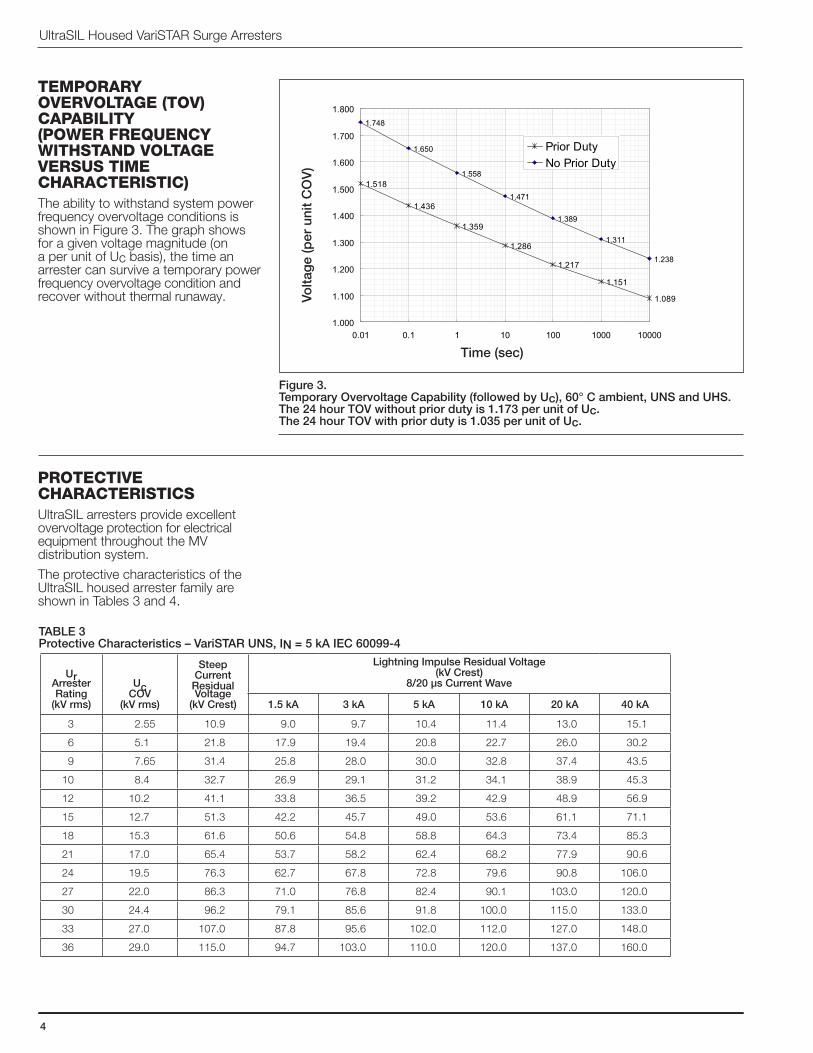
TEMpoRARy oVERVoLTAGE (ToV) CApAbILITy (poWER FREqUEnCy WITHSTAnD VoLTAGE VERSUS TIME CHARACTERISTIC)The ability to withstand system power frequency overvoltage conditions is shown in Figure 3. The graph shows for a given voltage magnitude (on a per unit of Uc basis), the time an arrester can survive a temporary power frequency overvoltage condition and recover without thermal runaway.
pRoTECTIVE CHARACTERISTICSUltraSIL arresters provide excellent overvoltage protection for electrical equipment throughout the MV distribution system.
The protective characteristics of the UltraSIL housed arrester family are shown in Tables 3 and 4.
Figure 3.Temporary Overvoltage Capability (followed by Uc), 60° C ambient, UNS and UHS. The 24 hour TOV without prior duty is 1.173 per unit of Uc. The 24 hour TOV with prior duty is 1.035 per unit of Uc.
TABLE 3Protective Characteristics – VariSTAR UNS, IN = 5 kA IEC 60099-4
UrArresterRating
(kV rms)
UcCOV
(kV rms)
Steep Current
ResidualVoltage
(kV Crest)
Lightning Impulse Residual Voltage(kV Crest)
8/20 µs Current Wave
1.5 kA 3 kA 5 kA 10 kA 20 kA 40 kA
3 2.55 10.9 9.0 9.7 10.4 11.4 13.0 15.1
6 5.1 21.8 17.9 19.4 20.8 22.7 26.0 30.2
9 7.65 31.4 25.8 28.0 30.0 32.8 37.4 43.5
10 8.4 32.7 26.9 29.1 31.2 34.1 38.9 45.3
12 10.2 41.1 33.8 36.5 39.2 42.9 48.9 56.9
15 12.7 51.3 42.2 45.7 49.0 53.6 61.1 71.1
18 15.3 61.6 50.6 54.8 58.8 64.3 73.4 85.3
21 17.0 65.4 53.7 58.2 62.4 68.2 77.9 90.6
24 19.5 76.3 62.7 67.8 72.8 79.6 90.8 106.0
27 22.0 86.3 71.0 76.8 82.4 90.1 103.0 120.0
30 24.4 96.2 79.1 85.6 91.8 100.0 115.0 133.0
33 27.0 107.0 87.8 95.6 102.0 112.0 127.0 148.0
36 29.0 115.0 94.7 103.0 110.0 120.0 137.0 160.0
Time (sec)
Volta
ge
(per
uni
t C
OV
)
UltraSIL Class 1 - 10kAVariSTAR Arrester
1.518
1.436
1.359
1.286
1.217
1.151
1.089
1.748
1.650
1.558
1.471
1.389
1.311
1.238
1.000
1.100
1.200
1.300
1.400
1.500
1.600
1.700
1.800
0.01 0.1 1 10 100 1000 10000
Time (sec)
Volta
ge (p
er u
nit C
OV)
Prior DutyNo Prior Duty
I235-35
5
InSULATIon WITHSTAnD CHARACTERISTICSTABLE 5Housing Insulation Withstand Voltages, Ur 3-36 kV, UNS and UHS, IN = 5 & 10 kA Class 1
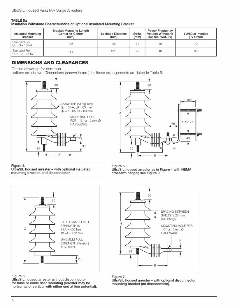
Figure 4.UltraSIL housed arrester – with optional insulated mounting bracket, and disconnector.
Figure 6.UltraSIL housed arrester without disconnector, for base or cable riser mounting (arrester may be horizontal or vertical with either end at line potential).
Figure 5.UltraSIL housed arrester as in Figure 4 with NEMA crossarm hanger, see Figure 9.
Figure 7.UltraSIL housed arrester – with optional disconnector mounting bracket (no disconnector).
DIMEnSIonS AnD CLEARAnCESOutline drawings for common options are shown. Dimensions (shown in mm) for these arrangements are listed in Table 6.
A
B
30
IN = 5 kA, O = 83 mmIN = 10 kA, O = 89 mm
DIAMETER (All Figures):
14
25
30
MOUNTING HOLE FOR 1/2" or 12 mm O HARDWARE
A
B
43
102-127
0-102
65
30 14
30
25
C
28
30
RATED CANTILEVERSTRENGTH IS5 kA = 450 Nm10 kA = 450 Nm
MAXIMUM PULLSTRENGTH (Tension)IS 5,000 N.
H
B
14
30
28
MOUNTING HOLE FOR 1/2" or 12 mm O HARDWARE
SPACING BETWEENSHEDS IS 27 mm (All Ratings)
TABLE 5aInsulation Withstand Characteristics of Optional Insulated Mounting Bracket
Insulated MountingBracket
Bracket Mounting Length Center-to-Center
(mm)Leakage Distance
(mm)Strike(mm)
Power FrequencyVoltage Withstand(60 sec, Wet, kV)
1.2/50µs Impulse(kV Crest)
Standard ForUr = 3 – 10 kV 105 150 71 36 70
Standard ForUr = 12 – 36 kV 127 226 99 48 80
I235-35
7
TABLE 6 Dimensional Data – UNS and UHS UltraSIL Housed VariSTAR Arresters
* All clearances are measured between centerlines of arresters or from centerline to earth.
UltraSIL Housed VariSTAR Surge Arresters
8
ULTRAQUIK SELECTION AND ORDERING GUIDE
Catalog Number Digits:
1 = “U”, UltraSIL Housed Arrester 2 = Arrester Class: N = IN = 5 kA (Ur = 3 to 36 kV) H = IN = 10 kA, Class 1 (Ur = 3 to 36 kV) 3 = Arrester Type: S = VariSTAR, Gapless MOV Surge Arrester
Notes:1. Protected leakage distance is approximately 45% of total leakage distance (mm).2. Total leakage distance shown includes 40 mm of the insulated base/mounting bracket.
I235-35
9
8 = Line Stud and Lead Options:
• 12 mm Line Terminal Options – all threaded studs are 12 mm x 30 mm long (except options L and M), stainless steel. A = without line lead B = with 300 mm long, 5 mm diameter E = with 450 mm long, 5 mm diameter H = with 750 mm long, 5 mm diameter insulated lead wire insulated lead wire insulated lead wire
C = with 300 mm long, 5 mm diameter F = with 450 mm long, 5 mm diameter J = with 750 mm long, 5 mm diameter insulated lead wire having insulated lead wire having insulated lead wire having (1) ring terminal (1) ring terminal (1) ring terminal
D = with 300 mm long, 5 mm diameter G = with 450 mm long, 5 mm diameter K = with 750 mm long, 5 mm diameter insulated lead wire having insulated lead wire having insulated lead wire having (2) ring terminals (2) ring terminals (2) ring terminals
L = with 45 mm long stud, without M = with 65 mm long stud, without insulated lead wire (will not allow insulated lead wire (will not allow use of universal wildlife protector) use of universal wildlife protector) • 3/8" Line Terminal Options – all threaded studs are 3/8" x 1-3/16" long, stainless steel.
0 = without line lead
1 = with 12" #6 AWG insulated lead wire 4 = with 18" #6 AWG insulated lead wire 7 = with 30" #6 AWG insulated lead wire
2 = with 12" #6 AWG insulated lead 5 = with 18" #6 AWG insulated lead 8 = with 30" #6 AWG insulated lead wire having (1) ring terminal wire having (1) ring terminal wire having (1) ring terminal
3 = with 12" #6 AWG insulated lead 6 = with 18" #6 AWG insulated lead 9 = with 30" #6 AWG insulated lead wire having (2) ring terminals wire having (2) ring terminals wire having (2) ring terminals
9 = Line Terminal Accessories
All line terminal accessory hardware is stainless steel (12 mm or 3/8" Ø, as required for digit 8)
Notes:
1. Wire clamps F R & U will accommodate #10 solid to 2/0 AWG or to 4 mm solid diameter wire. Wire clamp V will accommodate 6 mm solid or up to 14 mm diameter stranded conductor.
2. Maximum allowable torque on line terminal is 27 Nm.
3. The universal wildlife protector may only be used with 30 mm or 1-3/16” length stud.
C = No Hardware F= Nut, Wire Clamp & Universal L = 2 each: Nuts, Flat Washers & R = Nut & Wire Clamp Wildlife Protector Lock Washers (Requires “L” or “M” in Digit 8)
4545/65 mm
S = Nut, Lock Washer & T = Nut, Lock Washer (Also for U = Nut & 2 Wire Clamps V = Wire clamp, Nut, & Flat Washer Universal Wildlife Protector leads with ring terminals, see (Also for leads with ring Digit 8) terminals, see Digit 8)
UltraSIL Housed VariSTAR Surge Arresters
10
10 = Ground Terminal Options
• With ground lead disconnector
1 = Isolator with 3/8" x 1" long stainless steel stud (Requires “1” in digit 12)
D = Isolator with 12 mm x 25 mm long stainless steel stud (Requires “1” in digit 12)
• Without ground lead disconnector
0 = Stainless Steel Ground Terminal Stud, 3/8" x 1-3/16" long
A = Stainless Steel Ground Terminal Stud, 12 mm Ø x 30 mm long
B = Stainless Steel Ground Terminal Stud, 12 mm Ø x 45 mm long
C = Stainless Steel Ground Terminal Stud, 12 mm Ø x 65 mm long
11 = Ground Terminal Hardware All ground terminal accessory hardware is stainless steel (12 mm or 3/8" Ø, as required for digit 10)
Note: Maximum allowable torque on ground terminal is 27 Nm.
12 = Bracket Configurations
13 = Mounting Options
B = No Hardware V = Wire Clamp and Nut W = Washer, (Shown with optional discon- (Shown with optional Lock Washer, and Nut nector and Insulated mounting disconnector and bracket) Insulated mounting bracket)
0 = Base Mounted Arrester 1 = Insulated Mounting Bracket 2 = Conductive Mounting Bracket 3 = Conductive Mounting Bracket (Required with optional For 3/8" Hardware For 12 mm Hardware disconnector) (Requires “0” in Digit 10 and (Requires “A”, “B” or “C” in Available only if Digits 6 & 7 are “W” in Digit 11 ) See Figure 11 Digit 10 and “W” in Digit 11) See Housing Options 15 or less Figure 12
A = Without a B = NEMA Crossarm Hanger Mounting Bracket (Mounting Hardware Included) (Requires "1", "2" or "3" in Digit 12) See Figure 9
I235-35
11
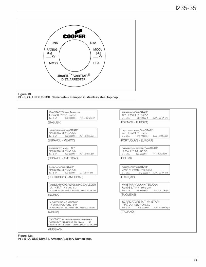
14 = Nameplate Information, See Figures 13 and 14
Nameplate information is per IEC 60099-4. Auxiliary nameplates are available in the following languages:
A = English
B = Español – Mexico
C = Españ ol – Americas
D = Português – Americas
E = Españ́ol – Europa
F = Português – Europa
G = Polski
H = Français
I = Norsk
J = Suomeksi
K = Greek
L = Italiano
M = Russian
ACCESSoRIES FoR THE UltraSIL ARRESTER
15 = Packaging.
1 = Individual carton. Each arrester with accessories is shipped in an individual cardboard carton. Individual cartons are packed within a heavy duty quadwall carton having a skid bottom and suitable for double stacking within an ocean shipping container.
2 = Individual carton. Each arrester is shipped in an individual cardboard carton. Individual cartons are stacked on a pallet and shrink wrapped, suitable for shipment within NAFTA. Quantities per pallet may be adjusted to meet shipping requirements.
Figure 9.NEMA crossarm hanger (all dimensions are as required to be in inches, per NEMA.)
ZEROTo
4.00
4.12 To
5.15
6.75
2.56
4.50
.344
1.25
.438SQUARE
.438 SQUAREHOLE
.5001.50
3/8" HARDWARE
1/2" HARDWARE
UltraSIL Housed VariSTAR Surge Arresters
12
Figure 10.Universal Wildlife Protector (for line terminal) adds 5 mm to arrester height above line terminal stud. To be used only with 3/8" or 12 mm Ø line hardware of standard length, 1-3/16" and 30 mm respectively.
20
64
26
56
SLOTSMAY BECUT HERE
UNIVERSALVALVE
OPENING
UNIVERSALVALVE
OPENINGUNIVERSALVALVEOPENING
SIDE VIEW TOP VIEW
152
Figure 11. Conductive base mounting for use with 3/8” hardware (requires “0” in digit 10, “W” in digit 11.
114
11 SQUARE
11 SQUAREHOLE
13
13
8
170
9
114
(2) 13 mm O
13
8
32
32
170
13
GALVANIZED STEEL(All dimensions in mm)
Figure 12. Conductive base mounting for use with 12 mm hardware (requires “A”, “B” or “C” in digit 10, “W” in digit 11.
114
11 SQUARE
11 SQUAREHOLE
13
13
8
170
9
114
(2) 13 mm O
13
8
32
32
170
13
(All dimensions in mm)
GALVANIZED STEEL(All dimensions in mm)
I235-35
13
Figure 13a.IN = 5 kA, UNS UltraSIL Arrester Auxiliary Nameplates.
Figure 13. IN = 5 kA, UNS UltraSIL Nameplate – stamped in stainless steel top cap.
UNS
RATING (Ur) ___ kV
MMyy
5 kA
MCOV (Uc) ___ kV
USA
UltraSIL™ VariSTAR®DIST. ARRESTER
APARTARRAYOS VARISTAR®
TIPO ULTRASIL™ UNS-ZNOIN = 5 kA IEC 60099-4
Ur = kVUc = kVAdP = 20 kA sim
Ur = kVUc = kVAdP = 20 kA sim
Ur = kVUc = kVSp = 20 kA sim
PARARRAYOS VARISTAR®
TIPO ULTRASIL™ UNS-ZNOIN = 5 kA IEC 60099-4
(ESPANOL - MEXICO)˜
VARISTAR® SURGE ARRESTERULTRASIL™ TYPE UNS-ZNOIN = 5 kA IEC 60099-4 P.R. = 20 kA sym
(ENGLISH)
(ESPANOL - AMERICAS)˜
PARA-RAIOS VARISTAR®
TIPO ULTRASIL™ UNS-ZNOIN = 5 kA IEC 60099-4
(PORTUGUEˆS - AMERICAS)
´´
PARARRAYOS VARISTAR®
TIPO ULTRASIL™ UNS-ZNOIN = 5 kA CEI 60099-4
Ur = kVUc = kVAdP = 20 kA sim
LdeS = 20 kA sim
Pr = 20 kA sym
DESC. DE SOBRET. VARISTAR®
TIPO ULTRASIL™ UNS-ZNOIN = 5 kA IEC 60099-4
(ESPANOL - EUROPA)˜
(PORTUGUEˆS - EUROPA)
OGRANICZNIK PRZEPIEC VARISTAR®
ULTRASIL™ TYP UNS-ZNOIN = 5 kA IEC 60099-4
(POLSKI)
Ur = kVUc = kVLdP = 20 kA sym
PARAFOUDRE VARISTAR®
MODELE ULTRASIL™ UNS-ZNOIN = 5 kA CEI 60099-4
(FRANÇAIS)
APARTARRAYOS VARISTAR®
TIPO ULTRASIL™ UHS-ZNOIN = 10 kA CLASE 1 IEC 60099-4
Ur = kVUc = kVAdP = 20 kA sim
Ur = kVUc = kVAdP = 20 kA sim
Ur = kVUc = kVSp = 20 kA sim
PARARRAYOS VARISTAR®
TIPO ULTRASIL™ UHS-ZNOIN = 10 kA CLASE 1 IEC 60099-4
(ESPANOL - MEXICO)˜
ULTRASIL™ TYPE UHS-ZNO
IN = 10 kA CLASS 1 IEC 60099-4 P.R. = 20 kA sym
(ENGLISH)
(ESPANOL - AMERICAS)˜
PARA-RAIOS VARISTAR®
TIPO ULTRASIL™ UHS-ZNOIN = 10 kA CLASSE 1 IEC 60099-4
(PORTUGUEˆS - AMERICAS)
´´
PARARRAYOS VARISTAR®
TIPO ULTRASIL™ UHS-ZNOIN = 10 kA CLASE 1 CEI 60099-4
Ur = kVUc = kVAdP = 20 kA sim
LdeS = 20 kA sim
Pr = 20 kA sym
DESC. DE SOBRET. VARISTAR®
TIPO ULTRASIL™ UHS-ZNOIN = 10 kA CLASSE 1 IEC 60099-4
(ESPANOL - EUROPA)˜
(PORTUGUEˆS - EUROPA)
OGRANICZNIK PRZEPIEC VARISTAR®
ULTRASIL™ TYP UHS-ZNOIN = 10 kA KLASA 1 IEC 60099-4
(POLSKI )
Ur = kVUc = kVLdP = 20 kA sym
PARAFOUDRE VARISTAR®
MODELE ULTRASIL™ UHS-ZNOIN = 10 kA CLASSE 1 IEC 60099-4
(FRANÇAIS)
VARISTAR® SURGE ARRESTER
VARISTAR® OVERSPENNINGSAVLEDERULTRASIL™ TYPE UNS-ZNOIN = 5 kA IEC 60099-4 KORTSLUTTKAP = 20 kA sym
(NORSK)
´´
RTV = 20 kA sym
VARISTAR® YLIJÄNNITESUOJAULTRASIL™ TYYPPI UNS-ZNOIN = 5 kA IEC 60099-4
(SUOMEKSI) A¥E•IKEPAYNO M.T. VARISTAR®
ULTRASIL™ TYPE UNS-ZNOIN = 5 kA IEC 600
(GREEK)
´P.R. = 20 kA sym
SCARICATORE M.T. VARISTAR®
TIPO ULTRASIL™ UNS-ZNOIN = 5 kA CEI 60099-4
(ITALIANO)
A¥E•IKEPAYNO M.T. VARISTAR®
ULTRASIL™ TYPE UNS-ZNOIN = 5 kA IEC 60099-4 KORTSLUTTKAP = 20 kA sym
(RUSSIAN)
´
VARISTAR® OVERSPENNINGSAVLEDERULTRASIL™ TYPE UHS-ZNOIN =10 kA KLASSE 1 IEC 60099-4 KORTSLUTTKAP = 20 kA sym