7
I2S Connectivity miniDSP kits v2.0 Revision Description Date V1.0 Technical note – Initial version 01-01-2009 V2.0 Adding section about configuration of kits as I2S slave 08-08-2010

I2S Connectivity
miniDSP kits
v2.0
Revision Description Date
V1.0 Technical note – Initial version 01-01-2009
V2.0 Adding section about configuration of kits as I2S slave 08-08-2010
MiniDSP kits include on-chip analog to digital (ADC) and digital to analog converters (DAC). They also have the ability to input/output digital audio signals in the I2S format (Inter IC Sound). The following technical note will clarify the system requirements to enable I2S connectivity on MiniDSP kits.
Disclaimer & Warning note
• This manual does not intend to cover the wealth of knowledge about I2S and other digital electronic concepts. I2S comes in a wide range of configurations (clock rates /ratio / bit depth…) and you should neve assume that I2S is plug&play. Do your homework in making sure signals will be compatible first.
• The target audience of this material is expected to have the necessary electronic background and knowledge required to understand the basic electronic concepts along with equipment to potentially troubleshoot his configuration (Scope/Logic analyzer).
• If you decide to customize our boards, be warned that it is outside of our support and you will be on your own. miniDSP technical support team simply can not support the wide range of ADC/DAC configurations.
• Finally, miniDSP cannot be held responsible to any damage you may do to your system or caused to the board by mis-use or mis-configuration. Warranty may be void if it is discovered that you damaged the board. With this being said we therefore strongly recommend that you first read forum posts about similar projects to gain necessary knowledge before starting any modifications to the board. About I2S I2S stands for Inter-IC Sound protocol and is most commonly used to carry audio information between IC’s. The bus consists of the following lines:
• MCLK: Master clock provided to the DSP IC. Must be synchronous with I2S clocks
• BCLK/SCLK: The bit clock line, in our case SCLK = 64 * LRCK = 64 * Fs
• LRCK: The frame synchronization which is equal to the sampling frequency (Fs)
• I2S_DATA_IN: Data input to the DSP IC. Signal available on expansion header
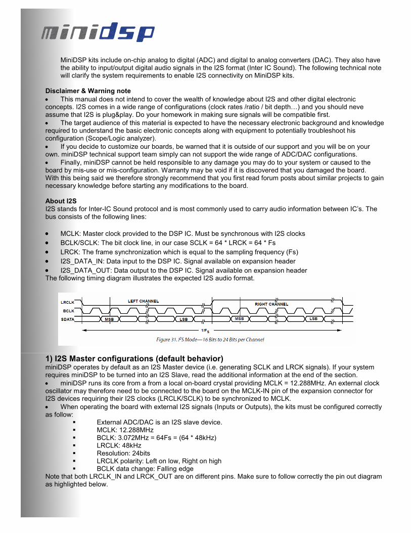
• I2S_DATA_OUT: Data output to the DSP IC. Signal available on expansion header The following timing diagram illustrates the expected I2S audio format.
1) I2S Master configurations (default behavior) miniDSP operates by default as an I2S Master device (i.e. generating SCLK and LRCK signals). If your system requires miniDSP to be turned into an I2S Slave, read the additional information at the end of the section.
• miniDSP runs its core from a from a local on-board crystal providing MCLK = 12.288MHz. An external clock oscillator may therefore need to be connected to the board on the MCLK-IN pin of the expansion connector for I2S devices requiring their I2S clocks (LRCLK/SCLK) to be synchronized to MCLK.
• When operating the board with external I2S signals (Inputs or Outputs), the kits must be configured correctly as follow:
External ADC/DAC is an I2S slave device. MCLK: 12.288MHz BCLK: 3.072MHz = 64Fs = (64 * 48kHz) LRCLK: 48kHz Resolution: 24bits LRCLK polarity: Left on low, Right on high BCLK data change: Falling edge
Note that both LRCLK_IN and LRCK_OUT are on different pins. Make sure to follow correctly the pin out diagram as highlighted below.

Board connectivity Before making any modification to your configuration, let’s look at the basic architecture of the device.
Pin Description
2 Analog out #3
4 Analog out #1
6 Ground
8 Ground
10 I2S_DATA_IN1&2
12 I2S_DATA_IN5&6
14 I2S_IN_LRCLK
16 I2S_DATA_OUT1&2
18 I2S_DATA_OUT5&6
20 I2S_OUT_LRCLK
22 3.3V
24 3.3V
26 GND
28 Analog In #2
Pin Description
1 Analog out #4
3 Analog out #2
5 Ground
7 Ground
9 MCLKIN
11 I2S_DATA_IN3&4
13 I2S_DATA_IN7&8
15 I2S_IN_BCLK
17 I2S_DATA_OUT3&4
19 IS2_DATA_OUT7&8
21 I2S_OUT_BCLK
23 5V - 300mA from USB
25 GND
27 Analog In #1
Pin Description
1 – 4 Ground
6 19 Reserved Pin
Could cause damage
if used improperly
5 Potentiometer input
10k-100kΩ
20 Potentiometer voltage
3.3V
21 Reserved Pin
Could cause damage
if used improperly
22 / 24 Ground
25 / 27 External DC input
4.5 ~ 24VDC
26 – 28 Reserved Pin
Do not use
Expansion Connector #1
5. Input RCA
connectors
4. MiniUSB 3. Button
Output RCA connectors
2. Expansion
connector #2
Pin 1
1. Expansion
connector #1
Master/Slave
jumper
Jumper in
Master position
Jumper in
Slave position S
M

Power Cycling/Boot up sequence By placing the MiniDSP in External Master Clock Slave mode, the MiniDSP requires a stable master clock (MCLK=12.288MHz) on Pin 9 of the expansion connector #2. This signal should come from a buffered clock to insure signal is clean at the DSP IC. MCLK signal is also required for the kit to power-cycle properly (i.e. microcontroller loading the program to the MiniDSP). The recommended power cycling procedure is therefore:
• Power on external device providing MCLK/LRCLK/BCLK signals
• Once clocking signals are stable, power on the MiniDSP kits. Any other sequencing order could lead to un-expected results as the MiniDSP may not be able to boot properly.
2) I2S Slave configuration miniDSP are by default configured as I2S master however, using a configuration file, it is possible to modify the configuration of the kit and turn them into I2S slave for some specific applications. The following section will explain in detail how to configure them as I2S slave. The following steps assume a similar hardware configuration than before, in other words:
I2S signals are synchronized to a single MCLK signal from a buffered source. (e.g. crystal oscillator.) miniDSP kit configured as a MCLK Slave device with center jumper.
At least one I2S device in your system is an I2S master providing LRCLK/SCLK MCLK: 12.288MHz. BCLK: 3.072MHz (64 * 48kHz) LRCLK: 48kHz Resolution: 24bits LRCLK polarity: Left on low, Right on high BCLK data change: Falling edge
Software configuration
1. Install the plug-in software on your computer. The Default installation path will be "C:\Program Files\miniDSP". If a previous version was installed, make sure to un-install first.
2. Once installation completed, we need to create a unique folder with the Board ID number to ensure that only this board will be configured as I2S slave in future synchronizations. The correct path for this folder is: “C:\Program Files\miniDSP \your_installation_path\your_plug-in_name\setting". To figure out your board ID, have a look at the synchronization pop up window. It will provide the board ID you need for the following steps.

Example
If my plug-in name is 2way-V5 and my board ID is 904848, I will need to create a folder called "904848" in the setting folder. C:\Program Files\miniDSP\MiniDSP-2way-V5\setting\904848 Note: Your board will NOT have this ID # since it is unique for each board, so make sure you follow step #2 to figure out what is your correct board ID #.
3. Next step, go to the "conf_file" folder in the “C:\Program Files\miniDSP\MiniDSP-2way-V5\setting\” and copy the "i2s_slave minidsp.conf" file into the newly created "904848" folder
"i2s_master_minidsp.conf" is the default settings configuration file "i2s_slave_minidsp.conf" is used for 2 minidsp + 1 minidigi.
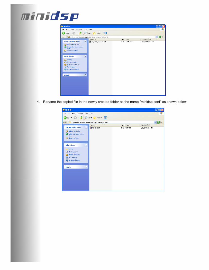
4. Rename the copied file in the newly created folder as the name "minidsp.conf" as shown below.

5. 5, Plug in the usb cable to one minidsp. Open the plug-in software and click on the Connect button
Click the "Restore to Default" at the prompt.
6. Once the restore to default complete, your board is now setup as an I2S slave and will be in that
state unless you delete the ID folder and Restore to default from the plug-in one more time. If any doubts, don’t hesitate to contact the miniDSP tech support team at [email protected] .


