51
Final Report 1999-30 I3 0314 00026 8l I 3 0314 00026 8200 hin~ Automatic Detection of Driver Fatigue - Phase III Minnesota Guidestar CTS TE 228.3 .K38 1999 L L

FinalReport 1999-30I3 0314 00026 8l I
3 0314 00026 8200
hin~
Automatic Detection ofDriver Fatigue - Phase III
Minnesota Guidestar
CTSTE228.3.K381999
LL


4I3< c 5 7•pTechnical Report Documentation Page
1. Report No. 2. 3. Recipients Accession No.
MN/RC - 1999-28
4. Title and Subtitle 5. Report Date
ARCHIVAL OF TRAFFIC DATA: Phase II December 19986.
7. Author(s) 8. Performing Organization Report No.
Shashi Shekhar
Xinhong Tan9. Performing Organization Name and Address 10. Project/Task/Work Unit No.
University of Minnesota
Computer Science 11. Contract (C) or Grant (G) No.
200 Union Street, S.E. (c) 71984 TOC# 138Minneapolis, Minnesota 5545512. Sponsoring Organization Name and Address 13. Type of Report and Period Covered
Minnesota Department of Transportation Final Report 1995-1998395 John Ireland Boulevard Mail Stop 330 14. Sponsoring Agency CodeSt. Paul, Minnesota 55155
15. Supplementary Notes
16. Abstract (Limit: 200 words)
Traffic centers gather information from traffic sensors at regular intervals, but storing the data for future analysisbecomes an issue. This report details work to improve the speed and effectiveness of traffic databases.
In this project phase, researchers redesigned the data model based on the previous phase's data model and decreasedthe storage requirements by one-third. Researchers developed a web-based Graphical User Interface (GUI) for usersto specify the query of interest; the outcome of the performance tuning gave users reasonable response time.
The beneficiaries of this effective database would include the driving public, traffic engineers, and researchers, whoare generally not familiar with the query language used in the database management system. This report summarizesthe detailed reference, such as benchmark query, sample data, table schema, conversion code, and other information.
17. Document Analysis/Descriptors 18. Availability Statement
Physical design Oracle implementation No restrictions. Document available from:
Graphic user interface Performance tuning National Technical Information Services,
Springfield, Virginia 2216119. Security Class (this report) 20. Security Class (this page) 21. No. of Pages 22. Price
Unclassified Unclassified 158

Automatic Detection of Driver Fatigue
Phase III Report
Prepared by:
Sarbjit Singh Kaur
Martin Eriksson
Nikolaos P. Papanikolopoulos
Artificial Intelligence, Robotics, and Vision Laboratory
Department of Computer Science
University of Minnesota
Minneapolis, MN 55455
June 1999
Published by
Minnesota Department of Transportation
Office of Research Services
First Floor
395 John Ireland Boulevard, MS 330
St. Paul, MN 55155
The contents of this report reflect the views of the authors who are responsible for the facts and accuracy of the data
represented herein. The contents do not necessarily reflect the views or policies of the Minnesota Department of
Transportation at the time of publication. This report does not constitute a standard, specification, or regulation.
The authors and the Minnesota Department of Transportation do not endorse products or manufacturers. Trade or
manufacturer's name appear herein solely because they are considered essential to the report.


AcknowledgmentsWe would like to thank Steve Hay and Ron Cassellius for their support.


Executive Summary
Sleep deprivation and sleep disorder are becoming a more common problem for car drivers
in a society in which people seem not to have enough time to perform all the activities they need to
carry out on a daily basis. Reducing the number of accidents related to driver fatigue would save the
society a significant amount of money and personal suffering. By monitoring the driver's
symptoms, we can determine driver fatigue early enough as to take preventive course to avoid an
accident due to lack of awareness.
This paper describes advances towards a non-intrusive approach for real-time detection of
driver fatigue. It uses a video camera that points directly towards the driver's face. It monitors the
driver's eye in order to detect micro-sleeps (short periods of sleep of about 3-4 seconds). The input
to the system is a continuous sequence of images fed from a video camera. From this sequence, the
system can analyze the eyes in each image, as well as compare the eyes between frames. The
system deals with skin-color information in order to search for the face in the input space. Allowing
only those pixels with skin like color to be considered, we perform blob operation in order to
determine the exact position of the face. We reduce the search space by analyzing the horizontal
gradient map of the face, taking into account the knowledge that eye regions in the face present
great changes in the horizontal intensity gradient. In order to find the exact location of the pupil, we
use gray scale model matching. Using this pattern recognition technique, we track the eyes in the
video frame sequence until we detect errors in the tracking module. We also use the same pattern
recognition technique to determine whether the eye is open or closed. If the eyes remain closed for
an abnormal number of times (3-4 sec) the system draws the conclusion that the person is falling
asleep and issues some kind of warning signal.
Alternatively, we have also developed a real-time face profile tracking system. By adding a
second camera to the system, we can detect fatigue in the form of backward or forward head
bouncing movements. As the face tracker, it uses a skin color based approach to locate the profile
and it performs blob statistics analysis to determine the inclination. The system is able to
automatically diagnose fatigue by continuously monitoring the face profile and counting the number
of consecutive frames in which the head has an abnormal forward or backward inclination.

The system uses a Pentium Pro 200 MHz personal computer with a Matrox Genesis imaging
board which holds a Texas Instruments TMS320C80 DSP chip. The system's performance is 15
frames per second for tracking and 10 frames per second for fatigue detection.
TABLE OF CONTENTS
CHAPTER 1 - INTRODUCTION........................................................................................... 1
CHAPTER 2 - OVERVIEW OF THE SYSTEM ..................................................................... 3
FUNCTIONAL DESCRIPTION................................................................................................................ 3EXPERIMENTAL SETUP........................................................................4
CHAPTER 3 - THE YE TRACKER ................................................................................ 7
LOCALIZATION OF THE EYES........................................................................................................... 7Localization of the Face ................................................................................................................ 7Computation of the Vertical Location of the Eyes .................................................................. 8Computing the Exact Location of the Eyes.................................. ......................................... 9Estimation of the Position of the Iris............................................................................... 11
TRACKING THE EYES ............................................................................................................... 12CALCULATING TRACKING ERROR ........................................................................................ 12SUM M ARY ........................................................................................................................................ 14
CHAPTER 4 - IMPROVING THE SYSTEM BY USING FACIAL FEATUREKNOWLEDGE ...................................................................................................................... .... 15
USING THE SKIN COLOR OF THE FACE .................................................................... 15TRACKING THE EYES .... ...................................................................................................... 18R ESULTS ....... ............ ....................................................................................................... ................... 20
CHAPTER 5 - DETECTION OF FATIGUE IN THE FORM OF MICRO-SLEEPS..............21
U SING EYE M ODELS ........... ............................................................................................................... 21USING THE HORIZONTAL HISTOGRAM ACROSS THE PUPIL ................................... ................. 22
CHAPTER 6 - DETECTION OF FATIGUE IN THE FORM OF BOUNCING HEADMOVEMENTS ........................................................................................................................... 25
TRACKING THE HEAD PROFILE ..................................... ............................................................... 25Determening The Profile Orientation ................................................................................... 25Tracking Profile Movement.................................................................................................. 28
DETERMINING DRIVER FATIGUE................................................................................................. 31RESULTS ......................................................................................................................................... 31SUM M ARY........................................................................................................................................ 32
REFERENCES ..... ....... ............ . ........................ 33


TABLE OF FIGURES
Figure 1. Flowchart diagram of the processing of each frame.............................Figure 2. The symmetry histogram....... ...................................... ................... 8Figure 3. The original image, the edges and the histogram of projected edges..........9Figure 4. Result after connected region extraction.. ............................................... 10Figure 5. The eye-template. ...... .......................... . . 11Figure 6. Iris localized from image ...................................................... ....... 12Figure 7. Snapshots from the system during tracking. Note that in the second image,
the system missed tracking of one eye................................ .......... 13Figure 8. Detection of face using skin color information .......................................... 17Figure 9. Tracking eyes............................. ......................................................... 19Figure 10. Sample open eye model....... .... . ................................... ............................. .19Figure 11. Closed eye model ..................................... ........ ....... ..................... 19Figure 12. Eye model used for detection of fatigue...................................................21Figure 13. Fatigue signal activated........................................................22Figure 14. Histograms corresponding to an open and a closed eye............................22Figure 15. Profile extraction from the scene................ ................................... 26Figure 16. Profile orientation ............... ................... ................... .. .. 28Figure 17. Sample forward bouncing movement due to fatigue ................................ 28Figure 18. Sample head back laying due to fatigue........................................ 29Figure 19.a. Multiple head bouncing (deg vs. frame number). .................................. 29Figure 19.b. Driver slowly falling asleep followed by a panic bounce............... 30Figure 19.c. Backward head falls............................................................30

CHAPTER 1
INTRODUCTION
Introduction
A large number of automobile accidents are caused due to driver fatigue. Sleeping deprivation
is becoming a more common problem for car drivers in a society in which people seem not to have
enough time to perform all the activities they need to carry out in a daily basis. Reducing the
number of accidents related to driver fatigue would save the society a significant amount of money
and personal suffering. By monitoring the driver's symptoms, we can determine driver fatigue early
enough as to take any preventive course to avoid an accident due to lack of awareness.
There are many indicators of oncoming fatigue, some of which are possible to detect by using a
camera. Two of the most notorious of these symptoms that we consider feasible to detect are
micro-sleeps (short periods, 2-3 seconds, in which the driver loses consciousness) and the forward
bouncing movement of the driver's head.
The input to the system is a continuous sequence of images fed from a video camera. From this
sequence, the system can analyze the eyes in each image, as well as compare the eyes between
images. The analysis of face images is a popular research area with applications such as face
recognition, virtual tools and handicap aids (White, Hutchinson and Carley, 1993) (Tello, 1983),
human identification and database retrieval (Cox, Ghosn and Yianilos, 1995). There are also many
real-time systems, being developed in order to track face features (Tock and Craw, 1995)
(Stiefelhagen, Yang and Waibel, 1996) (Xie, Sudhakar and Zhuang, 1995).
For our study of fatigue in the form of micro-sleeps, we have extracted and tracked the eye
locations through out the entire video sequence. This is a valuable information in order to detect
micro-sleep symptoms. We achieved this by dividing the problem into the following functional
phases:

1) Localization of the eyes (in the first frame),
2) Tracking the eyes in subsequent frames,
3) Detection of failure in tracking.
Localizing the eyes at the first frame is the most computationally expensive phase of the
system. In this phase, the system has no previous information about the eyes location in the image.
The system has to find the area of the image that will be used in the subsequent frames in order to
track the eyes. During the tracking phase, the search space is reduced as the system has an
approximate knowledge of the eye's position from the previous frame. This tracking can be done at
a relatively low computational effort. In order to detect failure in tracking, general constraints such
as the distance between the eyes and the horizontal alignment of the two eyes can be used. The eyes
should be relocated after a certain period, even though no failure has been detected, to periodically
make sure that the correct feature is being tracked.
For the detection of fatigue in the form of head bouncing movements we present a real-time
face profile tracking system. We add a second camera to the system, which detects fatigue in the
form of backward or forward head bouncing movements. As the face tracker, it uses a skin color
based approach to locate the profile and it performs blob statistics analysis to determine the
inclination.
This report is organized as follows: In Section 2, we describe the system operation. Section 3
describes the experimental setup. In Section 4 we describe the Eye Tracker, how we locate the eyes
and track them in a sequence of video input frames. Results and future work are discussed in
Section 5. Finally, Section 6 contains the conclusions.
CHAPTER 2
OVERVIEW OF THE SYSTEM
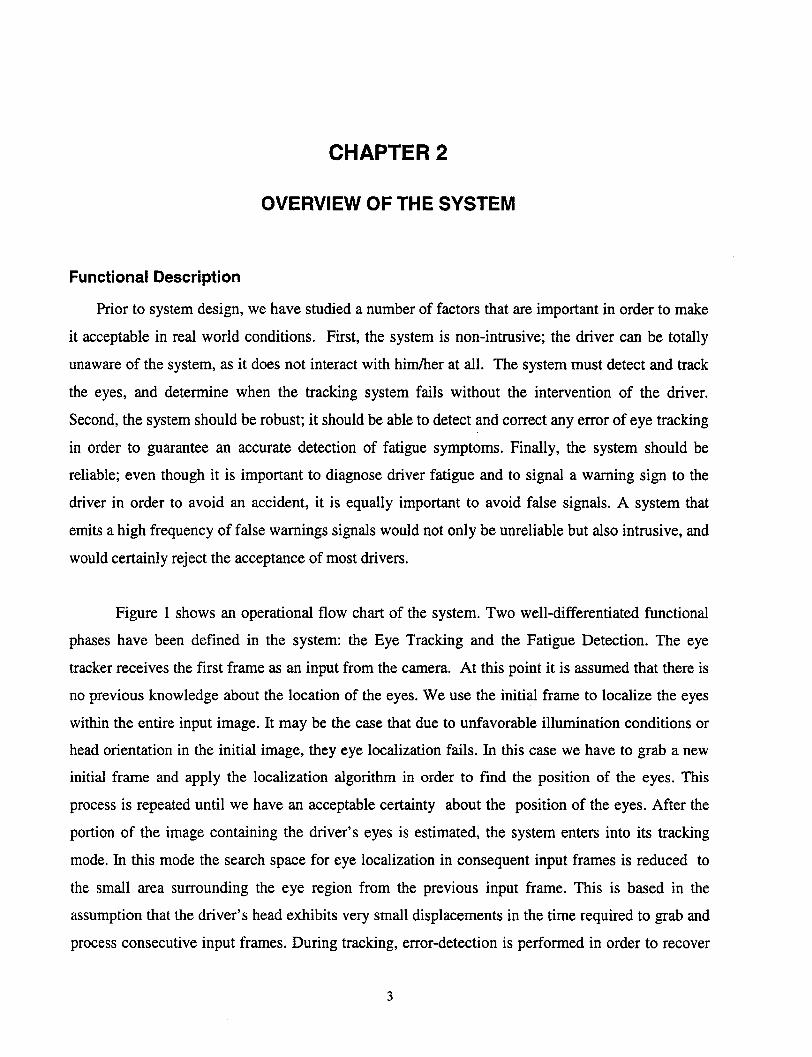
Functional Description
Prior to system design, we have studied a number of factors that are important in order to make
it acceptable in real world conditions. First, the system is non-intrusive; the driver can be totally
unaware of the system, as it does not interact with him/her at all. The system must detect and track
the eyes, and determine when the tracking system fails without the intervention of the driver.
Second, the system should be robust; it should be able to detect and correct any error of eye tracking
in order to guarantee an accurate detection of fatigue symptoms. Finally, the system should be
reliable; even though it is important to diagnose driver fatigue and to signal a warning sign to the
driver in order to avoid an accident, it is equally important to avoid false signals. A system that
emits a high frequency of false warnings signals would not only be unreliable but also intrusive, and
would certainly reject the acceptance of most drivers.
Figure 1 shows an operational flow chart of the system. Two well-differentiated functional
phases have been defined in the system: the Eye Tracking and the Fatigue Detection. The eye
tracker receives the first frame as an input from the camera. At this point it is assumed that there is
no previous knowledge about the location of the eyes. We use the initial frame to localize the eyes
within the entire input image. It may be the case that due to unfavorable illumination conditions or
head orientation in the initial image, they eye localization fails. In this case we have to grab a new
initial frame and apply the localization algorithm in order to find the position of the eyes. This
process is repeated until we have an acceptable certainty about the position of the eyes. After the
portion of the image containing the driver's eyes is estimated, the system enters into its tracking
mode. In this mode the search space for eye localization in consequent input frames is reduced to
the small area surrounding the eye region from the previous input frame. This is based in the
assumption that the driver's head exhibits very small displacements in the time required to grab and
process consecutive input frames. During tracking, error-detection is performed in order to recover
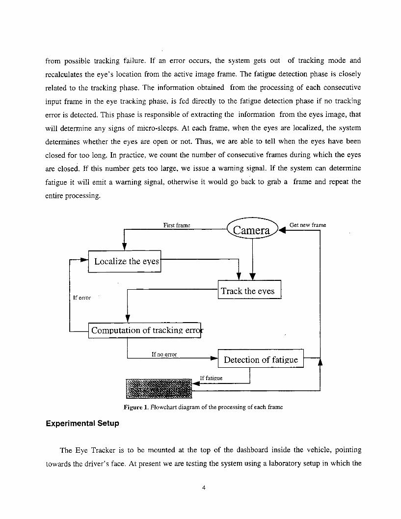
from possible tracking failure. If an error occurs, the system gets out of tracking mode and
recalculates the eye's location from the active image frame. The fatigue detection phase is closely
related to the tracking phase. The information obtained from the processing of each consecutive
input frame in the eye tracking phase, is fed directly to the fatigue detection phase if no tracking
error is detected. This phase is responsible of extracting the information from the eyes image, that
will determine any signs of micro-sleeps. At each frame, when the eyes are localized, the system
determines whether the eyes are open or not. Thus, we are able to tell when the eyes have been
closed for too long. In practice, we count the number of consecutive frames during which the eyes
are closed. If this number gets too large, we issue a warning signal. If the system can determine
fatigue it will emit a warning signal, otherwise it would go back to grab a frame and repeat the
entire processing.
Figure 1. Flowchart diagram of the processing of each frame
Experimental Setup
The Eye Tracker is to be mounted at the top of the dashboard inside the vehicle, pointing
towards the driver's face. At present we are testing the system using a laboratory setup in which the

camera is mounted on top of the computer monitor. The system does not have the capability to
control the tilt or zoom factors in order to adjust for the driver's head movements, however it is
advisable to have this capability in order to get a better resolution inside the region of interest in the
input image. For experimentation, we are using a JVC color video camera and for capturing and
image processing we use the Matrox Genesis imaging board which uses the Texas Instruments'
TMS320C80 DSP over a Pentium Pro 200 MHz personal computer.

CHAPTER 3
THE EYE TRACKER
As we had mentioned earlier the eye tracker can be divided into three functional units:
Localization of the Eyes
We localize the eyes in a top-down manner, reducing the search-space at each step. The steps
involved are:
Localization of the Face
Assuming a frontal view of the face initially, and assuming a horizontal symmetry on the
drivers face, we use an approach similar to (Yoo and Oh, 1996). He suggested that in an image
focusing a person's face, we can find the area containing the maximum horizontal symmetry to be
the vertical center line of the human face.
In order to increase computational speed we resample the input image of resolution of 640x480
into a 160x120 frame. A symmetry value is then computed for every pixel-column in the reduced
image. If the image is represented as I(x, y) then the symmetry-value for a pixel-column is given
by:
S(x) = [abs(I(x- w, y)- I(x+ wy))].w=l y=l
S(x) is computed for x e [k,xsize - k] where k is the maximum distance from the pixel-column
that symmetry is measured, and xsize is the width of the image. The x corresponding to the lowest

value surrounded by two peaks in the symmetry plot of S(x) is the center of the face. Once we have
found the symmetry of the face, we can consider the area within radius w from the centerline, as the
boundaries of the face. The result from this process is shown in Figure 2.
Figure 2. The symmetry histogram
By reducing the search space to the face area, not only do we gain speed for further
processing, but we also reduce the probability of having distracting features in the background.
Computation of the Vertical Location of the Eyes
As suggested in (Stringa, 1993), we use the observation that eye-regions correspond to regions
of high intensity gradients. This time using the reduced image from the previous unit, we create the
gradient-map, G(x,y). Any edge-detection method could be used. We choose to use a Sobel kernel
convolution. We then do a horizontal projection over G(x,y) by summing the gray level of pixels
along the horizontal rows :
xsize
H(y) = G(i, y),i=1
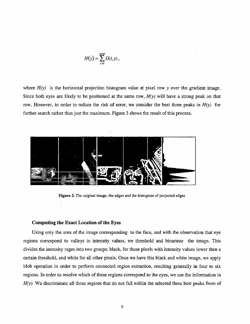
where H(y) is the horizontal projection histogram value at pixel row y over the gradient image.
Since both eyes are likely to be positioned at the same row, H(y) will have a strong peak on that
row. However, in order to reduce the risk of error, we consider the best three peaks in H(y) for
further search rather than just the maximum. Figure 3 shows the result of this process.
Figure 3. The original image, the edges and the histogram of projected edges
Computing the Exact Location of the Eyes
Using only the area of the image corresponding to the face, and with the observation that eye
regions correspond to valleys in intensity values, we threshold and binarieze the image. This
divides the intensity rages into two groups: black, for those pixels with intensity values lower then a
certain threshold, and white for all other pixels. Once we have this black and white image, we apply
blob operation in order to perform connected region extraction, resulting generally in four to six
regions. In order to resolve which of these regions correspond to the eyes, we use the information in
H(y). We discriminate all those regions that do not fall within the selected three best peaks from of

the H(y) plot. For discrimination we also use geometrical constraints as size, vertical displacement,
and distance from symmetry line. Figure 4 illustrates the result of this process.
Figure 4. Result after connected region extraction.
It must be taken into account that thresholding is the backbone step of this method. It is
difficult to establish a predefined threshold hold value that would satisfy all cases. Many different
factors intervene in the selection of this value, such are skin color, hair color, and illumination. We
have used an adaptive thresholding technique (Stiefelhagen, Yang and Waibel, 1996) that starts out
with a low threshold. If two good eye-regions are found, then threshold is stored, and used the next
time the eyes have to be localized. If no good eye-regions are found, the system automatically
attempts with a higher threshold, until the regions are found. When the threshold gets too high, the
system will start over with a low threshold again. If no good regions are found on any of the three
biggest peaks in H(y) with any of the attempted thresholds, we conclude that there are no eyes in
the image (e.g., the driver is looking over his shoulder). In this case the localization unit fails and
the entire localization process is repeated.
10

Estimation of the Position of the Iris
Once we have an estimated position of the location of the eyes in the image and using the
original 640x480 input frame, we apply a template matching technique over the eye region, in
order to localize the iris. Template matching refers to the process of detecting an object having a
certain size, shape, and orientation in an image by applying an operator containing positive weights
in a region resembling the object and negative weights surrounding the positive weights. To create
an operator that will respond to the match of the iris we use a template as show in figure 5. A good
match would result in many dark pixels in the area inside the inner circle, and many bright pixels in
the area between the two circles. This match occurs when the inner circle is centered on the iris and
the outside circle covers the sclera.
The match M(al,a2) is computed as
M(al,a2)= 1•(p,q)- _I(p,q).(p,q)ea l (p.q)ea2
A low valuefor M(al,a2) corresponds to a good Figure 5. The eye-template.
match.
We decided to use a fixed size template that does not deform taking into account the
desirability of a real time tracking system versus a highly accurate one.
11
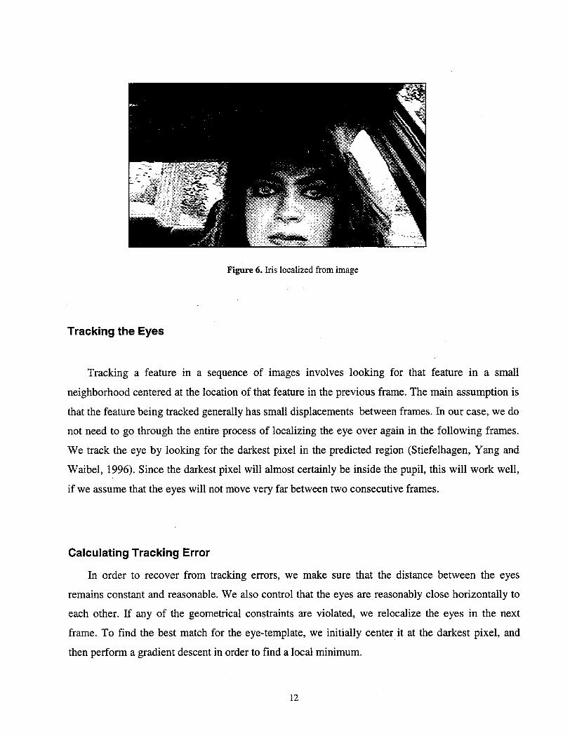
Figure 6. Iris localized from image
Tracking the Eyes
Tracking a feature in a sequence of images involves looking for that feature in a small
neighborhood centered at the location of that feature in the previous frame. The main assumption is
that the feature being tracked generally has small displacements between frames. In our case, we do
not need to go through the entire process of localizing the eye over again in the following frames.
We track the eye by looking for the darkest pixel in the predicted region (Stiefelhagen, Yang and
Waibel, 1996). Since the darkest pixel will almost certainly be inside the pupil, this will work well,
if we assume that the eyes will not move very far between two consecutive frames.
Calculating Tracking Error
In order to recover from tracking errors, we make sure that the distance between the eyes
remains constant and reasonable. We also control that the eyes are reasonably close horizontally to
each other. If any of the geometrical constraints are violated, we relocalize the eyes in the next
frame. To find the best match for the eye-template, we initially center it at the darkest pixel, and
then perform a gradient descent in order to find a local minimum.
12
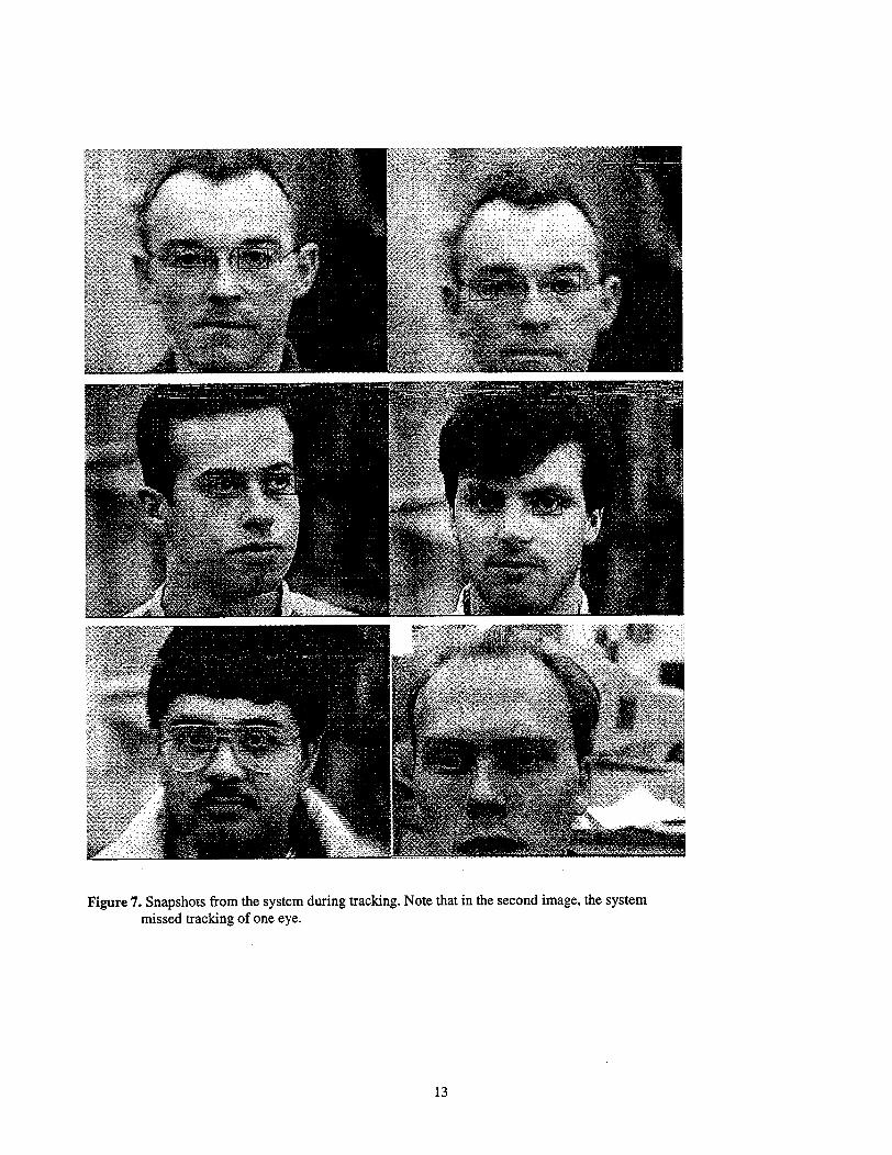
Figure 7. Snapshots from the system during tracking. Note that in the second image, the systemmissed tracking of one eye.
13
~~ _.____._ ___. _· ·__II

Summary
We have presented a non-intrusive real time eye tracking system. The system is able to localize
and track the pupil of a user as soon as he sits down in front of the video camera's view field. The
system uses a symmetry based approach to locate the face and template based eye feature
extraction. During tracking, the system is able to automatically detect any error that might have
occurred. In case of a tracking error, the system is able to recover and resume the proper tracking.
The Eye Tracker will provide useful information that will be further used in a micro-sleep detection
phase in order to achieve an automatic detection of driver fatigue.
14

CHAPTER 4
IMPROVING THE SYSTEM BY USING FACIAL FEATURE KNOWLEDGE
During this phase of the project, we have readapted the system to use color information. We
have used the skin color features of the face in order increase the robustness and information
inquired during the face location. We have improved our template matching algorithms in order to
quickly determine and track the location of the eyes. The same template matching technique is used
to find closed eyes, information that is later used to determine driver fatigue in the form of micro
sleep.
Finally we outline part of the research in progress related to capturing and tracking facial
features that will be helpful in determining fatigue by detecting the forward bouncing movement of
the driver's head.
Using the Skin Color of the Face
In the previous chapter, we had used a symmetry based approach in which it is assumed that
there exists a horizontal symmetry on human faces and that we could reduce the search space for
eyes by focusing our attention on a stripe of image around this symmetry line. This approach,
although very fast, showed to be quite fragile because the system expected that the driver's face be
in a totally frontal view every time the system entered into the face detection step. Moreover, the
technique gave information about the possible left and right margins of the face but was incapable
to provide any prediction of the upper and lower margins of the face.
We have adopted an approach that uses skin color feature information in order to predict and
track the position of the driver's face. Skin color models have shown to be very successful to
15
segment human faces in noisy images. We have used the approach suggested in [1]. The main idea
behind most skin color models lays on the notion that skin pixels do not vary as much in color as
they do in brightness. This is true even for individual among different races. In other words, given
an RGB representation of an image, and a pixel P1 with value [r,,gj,bI] in RGB space, and a pixel
P2 with value [r2,g2,b2], we say that they have similar color but possible different brightness if the
following expression ( described in [1 ) holds:
_. g1 b,
r2 g2 b2
As brightness is not important to represent human skin under normal light condition, we can
eliminate it by making a R3--R2 transformation from RGB space to chromatic color space (r,g) by
simple normalization
Rr=
R+G+B
Rg= R+G+B
Skin color pixels are clustered in chromatic color space and they can be represented using a
Gaussian distribution. For this purpose, we used as a sample space a representative portion of the
face of different people under different light condition. We represented the skin color distribution
using the Gaussian model N(m, X2), where m = (F, g), with
iN
= 1 :
N j=1
16

and
'rr rg
L[gr aogg
The procedure for creating skin color model is fully explained in [1,2]. Once the skin model was
created, we used it in our system to filter the incoming video frames to allow the filtering of only
those pixels that had a high likelihood of being face pixels. This allowed us to quickly detect the
region of the image where the face is located. In order to reduce the computational cost we resample
the input image of resolution of 640x480 into a 160x120 frame. Figure 8.b shows the result o
applying this method over the incoming video frame on Figure 8.a. As one may see, only those
pixels that resemble skin color have been admitted. In order to determine the exact face region from
the image we use simple blob operation (we chose the largest connected region as the face region).
Figure 8.c. shows binarization of the skin pixels and Figure 8.d. shows the result of the entire face
detection process after the blob operation is executed.
Figure 8.a. Incoming video frame
Figure 8.c. Binarization of sk
Figure 8.b. Skin color separation
in color image. Figure 8.d. Estimated face position after blob
operation.
Figure 8 Detection of face using skin color information
17

Tracking the eyes
After estimating the position of the eyes in the image as described in our previous chapter and
using the original 640x480 input frame, we use gray scale correlation over the eye region in order to
find the exact position of the iris. Gray scale correlation is a pattern matching technique that allows
us to search for a pattern in an image. Models were created and stored in a database using
rectangular areas of well-known sample eye images from different persons and at different face
angles (see Figure 10). A search is performed by assigning a match score to each pixel in the target
image, based on how closely the model matches the region around that pixel.
The match M is computed as
N N N
N IiM i -Z li M i
M =i=1 _i=1 i=lN N N NNEI i2-- )N2 N M i2- M) 2
i= =1 1=1 i 1 i=1
where N is the number of pixels in the model, M is the model and I is the image against which the
pattern is being compared.
We defined an acceptance level of match score above which a match is considered to be true. In
other words, if the match score of a pixel is above the acceptance level, we consider that the iris of
the eye is center at that pixel point; if the match score is below the acceptance level, we conclude
that the current pattern has no correspondence, and we use another model retrieved from the
database. On the other hand, if a match is found, a new model is grabbed from the live image and
used in future pattern matching. We do this in order to avoid searching the database in each eye
localization phase and to make the tracking process as smooth and accurate as possible.
Tracking a feature in a sequence of images involves looking for that feature in a small
neighborhood centered at the location of that feature in the previous frame. The main assumption is
that the feature being tracked generally has small displacements between frames. In our case, we do
not need to go through the entire process of localizing the eye in the following frames. If we assume
18

that the eyes will not move very far between two consecutive frames, we can predict that the next
eye match will happen almost certainly in an area surrounding the current iris position.
Figure 9. Tracking eyes
Figure 10. Sample open eye model Figure 11. Closed eye model
19

Results
We have tested the system with drivers of different skin color, with facial hair, and of different
gender. We have monitored the system's response with different degrees of rotation and inclination.
The system is able to complete the eye localization at 10 frames per second and tracking at 15
frames per second. For small head-movements, the system rarely loses track of the eyes. The system
has a tolerance on head rotation of up to 45 degrees and on tilt of up to 30 degrees. Under these
circumstances, the system was able to detect prolonged eye blinks most of the times and it produced
occasional false alarms.
20

CHAPTER 5
DETECTION OF FATIGUE IN THE FORM OF MICRO-SLEEPS
Using Eye models
As we had stated earlier in this paper, this system detects micro-sleeps symptoms in order to
diagnose driver fatigue. As the driver's fatigue increases, his/her eye blinks tend to last longer. We
can determine his blink rate by counting the number of consecutive frames in which the eyelashes
remain closed. Our main problem was to differentiate between an open eye, a closed eye and a total
absence of eyes in the given image. As the eye closes, we can be certain that the pattern-matching
algorithm will fail to keep track of the eye. However this notion should not always be interpreted as
tracking error. It is very possible that a closed eye may have caused the recognition failure. Taking
this into consideration, we have used a second model to keep track of the eye blinking. The model
we have used is that of a closed eye, as shown in Figure 12, and the technique used is exactly the
same as the one to find an open eye. If the tracking of the open eye fails, we try with the model of a
closed eye. If none of these models seem to produce an acceptable match, we declare the tracking
void and go back to the step relocating the eyes. Figure 13 shows how the system signals a "fatigue
alert" when the eyes have been closed for many consecutive input frames (3-4 seconds).
Sample open eye model Closed eye model
Figure 12. Eye model used for detection of fatigue
21

Figure 13 Fatigue signal activated
Using the Horizontal Histogram Across the Pupil
Another way to determine whether the eyes are open or closed is by using the characteristic curve
generated by plotting the image-intensities along the line going through the pupil from left to right.
The pupil is always the darkest point. Surrounding the pupil, we have the iris, which is also very
dark. To the right and left of the iris is the white sclera. In Figure 14 we show two curves, one
corresponding to an open eye, and one corresponding to a closed eye.
Figure 14. Histograms corresponding to an open and a closed eye
22

Note that the curve corresponding to the closed eye is very flat.
We compute the matching function M(x,y) as
M(x, y) = 1(x, y)/ min{l(x - r, y),l(x + r, y)}
where (x,y) is the computed center of the pupil and r is the radius of the iris. I(x,y) is the image
intensity at (x,y). When the eye is open, the valley in the intensity-curve corresponding to the pupil,
will be surrounded by two large peaks corresponding to the sclera. When the eye is closed, this
curve is usually very flat in the center. However, in the latter case there is no pupil to center the
curve on which can lead to a very unpredictable shape. In order to minimize the risk of having one
big peak nearby (due to noise), we always use the minimum peak at the distance r from the pupil.
This will lead to a good match when the eye is open, and very likely to a bad match when the eye is
closed. The reason that we can choose this method instead of using the match generated by the
circular template, is that the horizontal line captures the characteristic eye-colors more accurately
than a circular template does. A very good example of this is when the head is tilted forward. A
large fraction of the circular template would end up outside the eye, since the perspective makes the
eye "thinner." However, the histogram of the line going through the pupil will retain its
characteristic shape. This is a very important observation, since when the driver is getting tired, his
or her head is very likely to fall slightly forward.
23

24

CHAPTER 6
DETECTION OF FATIGUE IN THE FORM OF
BOUNCING HEAD MOVEMENTS
Tracking the Head Profile
In the earlier chapter of this report, we had studied the detection of eyes blink rate and other
facial futures for detection of micro-sleeps. The current task report examines the feasibility of
monitoring driver fatigue by analyzing the monition pattern of the driver's face profile. Studies in
the area have shown that certain patterns of motion of the face profile indicate driver fatigue (e.g.,
repetitive forward motion towards or against the steering wheel). Tracking the face profile enables
efficient monitoring of driver fatigue even when the driver eyes are out of the reach of a frontal
camera. We have used a second camera that tracks the driver's face profile which optical axis is
perpendicular to the optical axis of the frontal camera. The objective of this camera is to obtain
information about the head-moving pattern by tracking the driver's profile and determining his head
orientation in a continuos video feed.
Determining The Profile Orientation
In order to determine the profile orientation, the system first determines the location of the
face and separates it from the scene background. For this we have used a skin color based approach
already described in [1] (and in the Task 2 report) that takes advantage of the notion that skin pixels
do not vary as much in color as they do in brightness. This is true even for individuals among
different races.
25
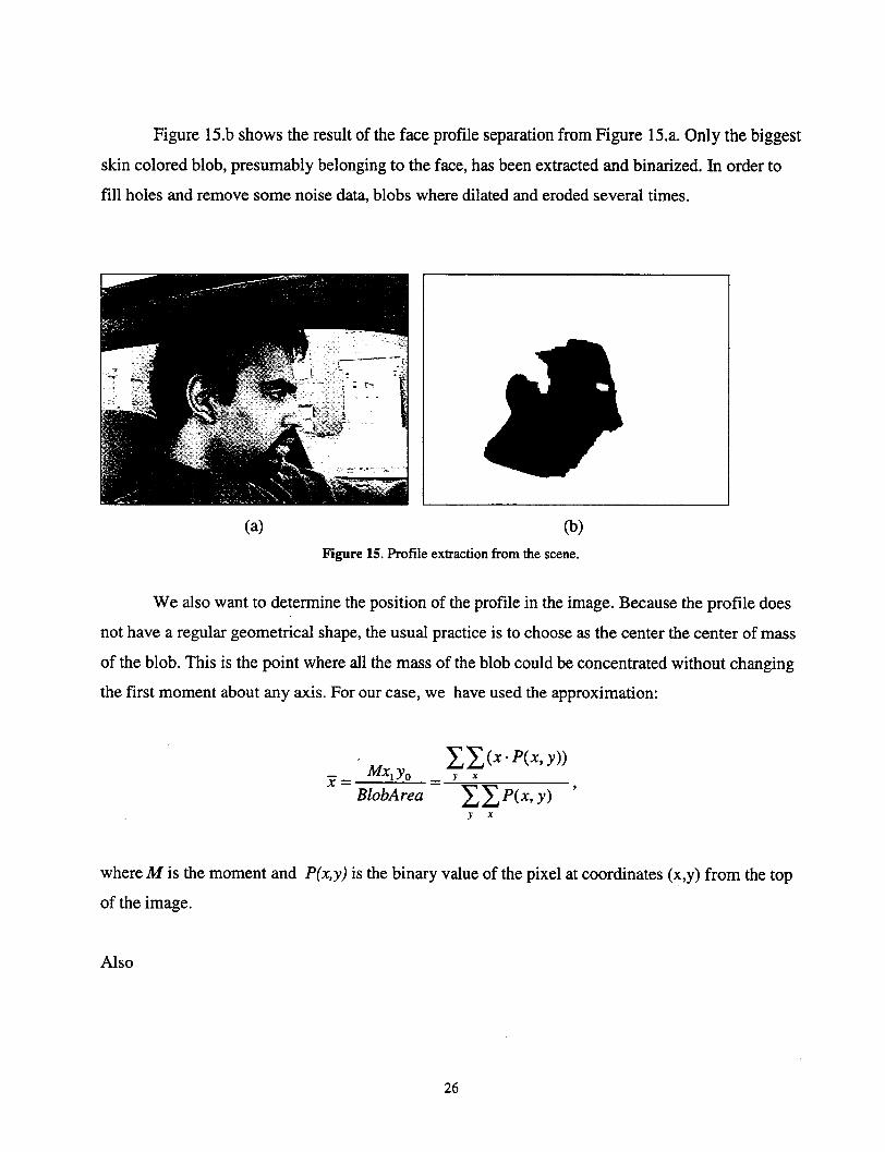
Figure 15.b shows the result of the face profile separation from Figure 15.a. Only the biggest
skin colored blob, presumably belonging to the face, has been extracted and binarized. In order to
fill holes and remove some noise data, blobs where dilated and eroded several times.
(a) (b)Figure 15. Profile extraction from the scene.
We also want to determine the position of the profile in the image. Because the profile does
not have a regular geometrical shape, the usual practice is to choose as the center the center of mass
of the blob. This is the point where all the mass of the blob could be concentrated without changing
the first moment about any axis. For our case, we have used the approximation:
X(x.- P(yx,y))Mx1Y0 y
BlobArea _1P(x,y)y x
where M is the moment and P(x,y) is the binary value of the pixel at coordinates (x,y) from the top
of the image.
Also
26

IxI((y. P(x, y))Mxoyl y .
SBlobArea Y (P(x, y))y x
Being (x, y) the center of gravity.
Now we determine how is the orientation of the face profile in the image as shown in Figure
16. Assuming that the head is somewhat elongated, the orientation of the elongation can be used to
define the inclination of the driver's face. We define the axis principal angle as the angle at which a
blob has the least moment of inertia. For elongated blobs, it is aligned with the longest axis. This
angle is calculated as follows:
1 2· Mcx, y,0 = -- arctan -.....2 Mcx2 0 - Mcxo y2
where Mc,, are the moments with respect to the center of gravity. Expanding this expression we
obtain:
2. _(x'y'P(x', y'))0= - -arctan y' x'
2 (x2. P(xc, yc)) - ,(y'2.p(x, y'))y' x' y' x'
(x',y') being the coordinates of the pixels with respect to the center of gravity.
27

Figure 16. Profile orientation
Tracking Profile Movement.
Having determined a method for calculating the head inclination, we proceeded to monitor it
in search for a pattern that would help us early diagnose fatigue. We mainly studied two kinds of
head movement pattern. The first one was the forward bouncing movements of the head, until the
driver totally loses sense with his head completely down, as in Figure 17.
The other very common symptom of driver unawareness due to fatigue is the total
inclination backwards as shown in Figure 18. However as you can see in the right most image, the
system may fail to predict the right inclination due to side tilt of the head.
Figure 17. Sample forward bouncing movement due to fatigue
28
Principal Axis7/
- X Axis
Gravity
'I I I I
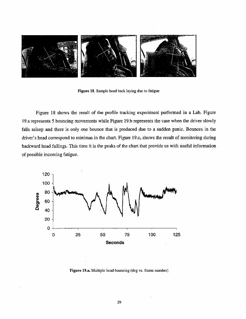
Figure 18. Sample head back laying due to fatigue
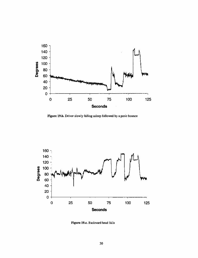
Figure 18 shows the result of the profile tracking experiment performed in a Lab. Figure
19.a represents 5 bouncing movements while Figure 19.b represents the case when the driver slowly
falls asleep and there is only one bounce that is produced due to a sudden panic. Bounces in the
driver's head correspond to minimas in the chart. Figure 19.c, shows the result of monitoring during
backward head fallings. This time it is the peaks of the chart that provide us with useful information
of possible incoming fatigue.
coc)C)
120
100
80
60
40
20
00 25 50 75 100
Seconds
Figure 19.a. Multiple head bouncing (deg vs. frame number)
125
29
0 25 50 75 100
Seconds
Figure 19.b. Driver slowly falling asleep followed by a panic bounce
25 50 75 100
125
125
Seconds
Figure 19.c. Backward head falls
30
U)
0)0n
0
IOU
140
120
100
80
60
40
20
0
L)
0)
0e
1..
160 -
140 -
120 -
100-
80-
60 -
40 -
20-
0-
0
1 1 1 I I
4 t-% f

Determining Driver Fatigue.
The method we have presented for tracking face profile, provides useful information about
the driver's head movement. However, the question on when to signal a fatigue alarm has yet to be
determined precisely. Determining a pattern that may be present in most users is a difficult task,
especially because we observe that different people have different head movement tendencies while
driving under fatigue and the may not even repeat among individual people. We can use heuristics
deduced from the charts to define an appropriate moment to emit a warning signal. In our case, we
emit a warning signal when the user's head inclination falls bellow 350 or goes beyond 1200 for
over 3 sec. Because these are movements that are very infrequent in a person while driving, we not
only maximize are chances of fatigue detection, but also avoid the signaling of constant false
positives.
The exact answer to when is the right moment to signal an alarm should come from
specialists in Human Factor or Psychologists. They can study better what patterns in the head
movement correspond to driver fatigue. We have designed our system in a flexible way to adapt for
any future knowledge in the area.
Results
We have tested the system with drivers of different skin color, with facial hair, different gender,
and with eye-glasses. We have monitored the system's response with different degrees of head
inclination. The system tracks the persons profile at 10 frames per second. The system rarely loses
track of the person's profile, however it may determine a wrong profile inclination of some
backfalling head movement especially in those with pronounced side tilts. Including these rare
special cases, the system was able to detect fatigue in 90% of the cases, and almost never produced
false'alarm.
31

Summary
We have presented a non-intrusive real-time face profile tracking system. We have added a
second camera to the system, which detects fatigue in the form of backward or forward head
bouncing movements. Similarly to the face tracker, it uses a skin color based approach to locate
the profile and it performs blob statistics analysis to determine the inclination. The system is able to
automatically diagnose fatigue by continuously monitoring the face profile and counting the number
of consecutive frames in which the head has an abnormal forward or backward inclination.
32
REFERENCES
[1] Craw, I., Ellis, H. and Lishman, J.R. (1987) "Automatic Extraction of Face-Features," Pattern
Recognition Letters, 5, pp. 183-187.
[2] De Silva, L.C., Aizawa, K. and Hatori, M. (1995) "Detection and Tracking of Facial Features by
Using Edge Pixel Counting and Deformable Circular Template Matching," IEICE Transaction
on Information and Systems, Vol. E78-D No 9, pp. 1195-1207, September.
[3] Baluja, S. & Pomerleau, D. (1994). "Non-intrusive Gaze Tracking Using Artificial Neural
Networks," Research Paper CMU-CS- School of Computer Science, Carnegie Mellon
University, Pittsburgh PA, USA.
[4] Brunelli, R.,. and Poggio, T. (1993) "Face Recognition: Features Versus Templates," IEEE
Transactions on Pattern Analysis and Machine Intelligence, Vol. 15, No 10, pp. 1042-1052.
[5] Chow, G. and Li, X. (1993) "Towards a System for Automatic Feature Detection," Pattern
Recognition, Vol. 26, No. 12, pp. 1739-1755.
[6] Cox, I.J., Ghosn, J. and Yianilos, P.N. (1995) "Feature-Based Recognition Using Mixture-
Distance," NEC Research Institute, Technical Report 95 - 09.
[7] Dijk, D.J. and Czeisler, C.A. (1994) "Paradoxal Timing of the Circadian Rhythm of Sleep
Propensity Serves to Consolidate Sleep and Wakefulness in Humans," Neuroscience Letters,
Vol. 166, pp. 63-68.
[8] Dinges, D.F. "An Overview of Sleepiness and Accidents," Journal of Sleep Research
(supplement), 4, pp. 1-11, 1995.
[9] Huang, C. L. and Chen, C.W. (1992) "Human Facial Feature Extraction for Face Interpretation
and Recognition," Pattern Recognition, Vol. 25, No. 12 pp. 1435-1444.
33

[10] Hutchinson, R.A. (1990), "Development of an MLP feature location technique using
preprocessed images," In proceedings of International Neural Networks Conference, 1990.
Kluwer
[11] Jochem, T.M., D.A. Pomerleau, C.E. Thorpe (1993), "MANIAC: A Next Generation Neurally
Based Autonomous Road Follower". In Proceedings of the International Conference on
Intelligent Autonomous Systems (IAS-3).
[12] Kass, M., Witkin, A. and Terzopoulos, D. (1988) "Snakes: Active Contour Models,"
International Journal of Computer Vision, pp. 321-331.
[13] Li, X. and Roeder, N. (1995) "Face Contour Extraction From Front-view Images," Pattern
Recognition, Vol. 28, No. 8, pp. 1167-1179.
[14] Nodine, C.F., H.L. Kundel, L.C. Toto & E.A. Krupinksi (1992) "Recording and analyzing
eye-position data using a microcomputer workstation", Behavior Research Methods,
Instruments & Computers 24 (3) 475-584.w
[15] Pomerleau, D.A. (1991) "Efficient Training of Artificial Neural Networks for Autonomous
Navigation," Neural Computation 3:1, Terrence Sejnowski (Ed).w
[16] Roeder N. and Li, X. (1996) "Accuracy Analysis for Facial Feature Detection" Pattern
Recognition, Vol. 29, No. 1, pp. 143-157.
[17] Segawa, Y., Sakai, H., Endoh, T., Murakami, K., Toriu, T. and Koshimizu, H. (1996) "Face
Recognition Through Hough Transform for Irises Extraction and Projection Procedures for Parts
Localization," Pacific Rim International Conference on Artificial Intelligence, pp. 625-636.
[18] Stringa, L. (1993) "Eyes Detection for Face Recognition," Applied Artificial Intelligence, No 7,
pp. 365-382.
[19] Stiefelhagen, R., Yang, J. and Waibel, A. (1996) "A Model-based Gaze-Tracking System,"
International IEEE Joint Symposia on Intelligence and Systems, pp. 304-310.
[20] Tello, E.R. (1983) "Between Man and Machine," BYTE, September, pp. 288-293.
34
[21] Tock, D. and Craw, I. (1995) "Tracking and Measuring Drivers Eyes," Real-Time Computer
Vision, pp. 71-89.
[22] White, K.P., Hutchinson, T.E. and Carley, J.M. (1993) "Spatially Dynamic Calibration of an
Eye-Tracking System," IEEE Transactions on Systems, Man, and Cybernetics, Vol. 23, No. 4,
pp. 1162-1168.
[23] Wu, H., Chen, Q. and Yachida, M. (1996) "Facial Feature Extraction and Face Verification,"
IEEE Proceedings of International Conference of Pattern Recognition, pp. 484-488.
[24] Xie, X., Sudhakar, R. and Zhuang, H. (1994) "On Improving Eye Features Extraction Using
Deformable Templates," Pattern Recognition, Vol. 27, No 6, pp. 791-799.
[25] Xie, X. Sudhakar, R. and Zhuang, H. (1995) "Real-Time Eye Feature Tracking from a Video
Image Sequence Using Kalman Filter," IEEE Transactions on Systems, Man, and Cybernetics,
Vol. 25, No. 12, pp. 1568-1577.
[26] Yoo, T.W. and Oh, I.S. (1996) "Extraction of Face Region and Features Based on Chromatic
Properties of Human Faces," Pacific Rim International Conference on Artificial Intelligence,
pp. 637-645.
35

36


