22 1 INTRODUCTION Bridges have traditionally been designed by imminent individual and visionary engineers. This is universal all over the world. Bridge conceptual development, design and construction has been considered an art based of- ten more on structural intuition than being the result of detailed design and analysis. This situation has changed considerably with the advance in structural engineering and other non-engineering factors influenc- ing the design decisions for major fixed links. The case for a multidisciplinary approach in the future is presented which takes advantage of the immense progress in the state-of- the- art for bridge engineering and takes into account other important influential fac- tors of the modern time in an ever increasing complex world. Although bridge engineering in itself is a key discipline in the process, it plays a smaller role in the overall political decision process. The bridge has to be functional, look excellent, have signature character etc. but people do basically resist to changes from what they know and are comfortable with. Environmentalists defend the existing environ- ment and do basically not want changes. The concerns about climate, CO2 emissions and the expected lack of energy resources make people hesitant or nervous. Local people resist because of risks of local impact from noise, air and water pollution, and increased traffic congestions etc. Bridge- and traffic experts may be looked upon as technocrats who are constantly pushing for more of the same (more asphalt, more concrete and more steel) without consideration to other factors affecting society. The result is that bridges and infrastructure developments often loose in the political prioritization against hospitals, schools and other important welfare in spite of the fact that they most often pay for themselves faster than expected seen from a macro-economical view and contribute to society efficiently. Excellent projects are therefore often abandoned or postponed indefinitely because of poor preparation for decision makers and politicians who need quick results. This has been the case for i.e. the Channel Tunnel, Storebelt Link, etc. - This is not necessarily to the long term advantage of the society as a whole. And this in spite of the fact, that once built the bridges do not only contribute to solving a traffic problem and stimulate economic growth, but also become landmarks of high society value and symbols of technology and develop- ment, worthy additions to the landscapes and touristic value at the time they are built and even illustrated on stamps and money bills for the aftermath as cultural heritage. Perfect examples are Brooklyn Bridge, Forth Bridge, Bosporus bridges, Golden Gate Bridge, Storebelt Bridge, and many others. We have to be aware of, and recognize, that the general public is becoming increasingly well educated so they may have a qualified opinion and may voice their opinion and thereby bringing the decision process into the public, sometimes with unpredictable results. IABSE-JSCE Joint Conference on Advances in Bridge Engineering-II, August 8-10, 2010, Dhaka, Bangladesh. ISBN: 978-984-33-1893-0 Amin, Okui, Bhuiyan (eds.) www.iabse-bd.org Major fixed links - approach to the future climatic, environmental and societal requirements in planning, design and construction Klaus H. Ostenfeld Expert Consultant COWI A/S, Copenhagen, Denmark Past President, IABSE ABSTRACT: The decision process for planning, design and construction of major fixed links has developed considerably and become more complex than previously. The challenge has shifted from the pure design and proof of structural adequacy, to become multidisciplinary because of two trends: The methods of analysis and check of various structural configurations have improved immensely because of modern computer software and high capacity computers capable of analysing the most complex structure, even including higher order ef- fects. The Society, at the same time, require much more comprehensive documentation and justification with high transparency as a basis for debate and dialogue in connection with the decision process. These trends shift the focus of leadership from the specialised bridge engineer towards a more comprehensive approach with other investigations to be performed by other disciplines, i.e. climate- and environmental engineers, re- source experts, economists, risk managers, planners, biologists, energy experts, logistics experts, architects and many others. In addition, employment and currency aspects import/export as well as political aspects en- ter the complicated decision complex. Based on a.o. northern European experience an integrated approach is proposed to respond to these future challenges as well as the need for future development in materials and bridge systems are addressed.
Transcript
22
1 INTRODUCTION
Bridges have traditionally been designed by imminent individual and visionary engineers. This is universal all over the world. Bridge conceptual development, design and construction has been considered an art based of-ten more on structural intuition than being the result of detailed design and analysis. This situation has changed considerably with the advance in structural engineering and other non-engineering factors influenc-ing the design decisions for major fixed links.
The case for a multidisciplinary approach in the future is presented which takes advantage of the immense progress in the state-of- the- art for bridge engineering and takes into account other important influential fac-tors of the modern time in an ever increasing complex world. Although bridge engineering in itself is a key discipline in the process, it plays a smaller role in the overall political decision process.
The bridge has to be functional, look excellent, have signature character etc. but people do basically resist to changes from what they know and are comfortable with. Environmentalists defend the existing environ-ment and do basically not want changes. The concerns about climate, CO2 emissions and the expected lack of energy resources make people hesitant or nervous. Local people resist because of risks of local impact from noise, air and water pollution, and increased traffic congestions etc. Bridge- and traffic experts may be looked upon as technocrats who are constantly pushing for more of the same (more asphalt, more concrete and more steel) without consideration to other factors affecting society.
The result is that bridges and infrastructure developments often loose in the political prioritization against hospitals, schools and other important welfare in spite of the fact that they most often pay for themselves faster than expected seen from a macro-economical view and contribute to society efficiently.
Excellent projects are therefore often abandoned or postponed indefinitely because of poor preparation for decision makers and politicians who need quick results. This has been the case for i.e. the Channel Tunnel, Storebelt Link, etc. - This is not necessarily to the long term advantage of the society as a whole. And this in spite of the fact, that once built the bridges do not only contribute to solving a traffic problem and stimulate economic growth, but also become landmarks of high society value and symbols of technology and develop-ment, worthy additions to the landscapes and touristic value at the time they are built and even illustrated on stamps and money bills for the aftermath as cultural heritage. Perfect examples are Brooklyn Bridge, Forth Bridge, Bosporus bridges, Golden Gate Bridge, Storebelt Bridge, and many others.
We have to be aware of, and recognize, that the general public is becoming increasingly well educated so they may have a qualified opinion and may voice their opinion and thereby bringing the decision process into the public, sometimes with unpredictable results.
IABSE-JSCE Joint Conference on Advances in Bridge Engineering-II, August 8-10, 2010, Dhaka, Bangladesh. ISBN: 978-984-33-1893-0 Amin, Okui, Bhuiyan (eds.) www.iabse-bd.org
Major fixed links - approach to the future climatic, environmental and societal requirements in planning, design and construction
Klaus H. Ostenfeld Expert Consultant COWI A/S, Copenhagen, Denmark Past President, IABSE ABSTRACT: The decision process for planning, design and construction of major fixed links has developed considerably and become more complex than previously. The challenge has shifted from the pure design and proof of structural adequacy, to become multidisciplinary because of two trends: The methods of analysis and check of various structural configurations have improved immensely because of modern computer software and high capacity computers capable of analysing the most complex structure, even including higher order ef-fects. The Society, at the same time, require much more comprehensive documentation and justification with high transparency as a basis for debate and dialogue in connection with the decision process. These trends shift the focus of leadership from the specialised bridge engineer towards a more comprehensive approach with other investigations to be performed by other disciplines, i.e. climate- and environmental engineers, re-source experts, economists, risk managers, planners, biologists, energy experts, logistics experts, architects and many others. In addition, employment and currency aspects import/export as well as political aspects en-ter the complicated decision complex. Based on a.o. northern European experience an integrated approach is proposed to respond to these future challenges as well as the need for future development in materials and bridge systems are addressed.
23
I will try to address how we, as structural engineers, may be able to improve our contribution in the future by a multidisciplinary integrated organizational approach, and thinking and communicating in a holistic way about the projects during their planning and preparation phases. In addition to this be open for new ideas and developments with cross border inspiration between related industries, which can save materials, resources and cost as well as leading to increased safety.
2 THE MULTIDISCIPLINARY APPROACH
The answer to some of these challenges lies in the thinking and organising the concept development in a multi stakeholder fashion.We need to think in integrated cyclic and iterative design development processes in inte-grated teams. - Integrated multidisciplinary teams with all relevant expertise areas and stakeholder interests represented. We need up front to think of all interested parties, official as well public opinion NGO's etc. Fig. 1: Parameters influencing design decisions And we need to address all relevant issues - not as afterthoughts and add on's,- but as valid important parame-ters that would have a real influence on the direction of the development, investigations and decisions. We must deal with these new challenges as experienced structural bridge engineers rather than only the bridge engineering art. At the same time it provides even more interesting opportunities and we may in the process be proud that we will be able to set new standards and make a better contribution to our society. If we under-stand and respond to these mechanisms we may experience that we as engineers will have more influence, be recognised and become more publicly visible as the multidisciplinary creator of the magnificent link as a positive addition to the society with due balanced consideration of all relevant aspects.
Fig. 2: Project development phases
M a st e r P la n n in g & P o l i ti c a l P r o c e s s
C o n c e p t & F e a s ib i l i t y S tu d ie s
P o l i ti c a l D e c is io n
P la n n i n g - d e ta i l e d
D e s i g n
C o n s tr u c tio n
O p e r a t io n & M a in t e n a n c e
D e c o m m is s io n in g
S o c i o -E c o n o m ic a s p e c t sT ra n s p o rt & E n v ir o n m e n tA e s t h e t ic sT e c h n ic a l C o n s t ra in t sS k e t c h e s & C o n c e p t s
C l i e n t o rg a n i s a t io nM a n a g e m e n t s t ra te g ie sF in a n c i n g
R i s k & N a v ig a t i o n S t u d i e sP r o c u re m e n t S t ra te g ie sD e s ig n B a s i sE n vi ro n m e n t a l B a s e l in e S tu d ie sE n vi ro n m e n t a l C o n d i t io n s & L o a d sD u ra b i l i t y S t ra te g yL if e C y c l e C o s t A n a l y s e sA e s th e t ic s
M a te r ia l iz in g S t ra te g ie s a n d A im s in D e s ig n
R e a l iz e D e s i g n s
24
When we think of project development we traditionally think linearly (vertical down on the picture Fig 2) and we become frustrated when and if the process is stalled because of some unexpected interference from a stakeholder - an environmental consequence for ex. Our fragile process is spoiled, the project delayed and most likely cost affected negatively. If we plan for a multi stakeholder approach we may be in for a positive surprise. - There will be no opponents, because all relevant interests will be part of the cyclic process and are being taken into account or understand why there suggestions might not be taken into account. It looks more complicated, and it is more complicated, but it pays off in the other end with fewer delays and a more positive support for the project
Fig. 3: Decision and cost impact vs. project development phases It is important that the integrated approach is thought into the process from the very beginning if delays and associated additional costs are to be avoided. All stakeholders know that the possibility for decisive global influence is in the initial phases of the project process. The flexibility is great, and the cost impact of changing decisions can be minimized up front. In the later phases the process becomes more determined and production oriented. Decisions are committed, and changes cost time and money and possibly even reduced quality because of interference into an otherwise well planned and structured process. The most important time to be open for new ideas and problem areas is up front in what we could call the ho-listic approach in the early phases. Fig. 4: Integrated Multidisciplinary approach A simple model illustrates some of the many parameters to include in the process. The all may have a signifi-cant impact on the early choice of solutions and decisions. The project team should of course include the relevant persons with the required expertise The result is a more dynamic team where nothing is taken for granted and all participants have the right to question and participate in the step wise decisions.
25
It sharpens the arguments, and makes decisions better and well founded. As we all know innovation is most often generated in the interfaces between various disciplines. Such an integrated team has a much higher likelihood of generating new innovative ideas by the mutual inspi-ration amongst people of different background and expertise than the more traditional mono-disciplinary ap-proach with the design being checked afterwards for compliance by other interested parties.
3 THE MAJOR FIXED LINKS IN NORTHERN EUROPE
Fig. 5 Major Fixed Links in Europe Let us illustrate the development towards such processes through the 3 very big fixed links in Northern Europe around and in Denmark.
• The StoreBelt link between East and West Denmark. Built 1988 - 1998 • The Oeresund link between Denmark and Sweden linking the 2 major cities Copenhagen and Malmo
on either side. Built 1993 - 2001 • The Fehmarn Belt link between Denmark and Germany currently under design.
They are all 16 - 20 km in length approx. They all cross significant navigable waters linking the Baltic Sea east of Denmark with the North Sea west of Denmark. They are however all different in need and purpose as well as bathymetry of the sea bottom: Storebelt is a Danish national east-west regional link with relatively deep water with intermediary island and crossing an international navigation route. Oeresund is an international transit link north-south connecting Scandinavia with central Europe, and at the same time a major metropol link between Copenhagen and Malmö across relatively shallow water with an intermediary island. Fehmarn is an international transit link north-south only with deep water and no intermediary island. Ship navigation is dominating for Storebelt and Fehmarn with the largest ships in the world passing, and of less importance for Oeresund. The final configu-rations are therefore quite different.
4 THE STOREBELT LINK
The Main East bridge of Storebelt is a beautiful structure well adapted to its danish environment with a main span of 1624 m and comprising a continouous slender aerodynamic steel box girder . The close cooperation between engineers and architects resulted in a pylon shape with no cross girders below the box girder and tapered legs, which make for a better appearance and better performance for ship colli-sions. The bridge box girder is smooth and completely joint free for its full length - traditionally maintenance is of-ten required at expansion joints and bearings, so they should be minimised - a result of design and mainte-nance experts and architects working together in a joint team.
26
Fig. 6: The Storebelt East bridge
Fig. 7: The Storebelt East bridge elevation
Fig. 8: Storebelt anchor structure
27
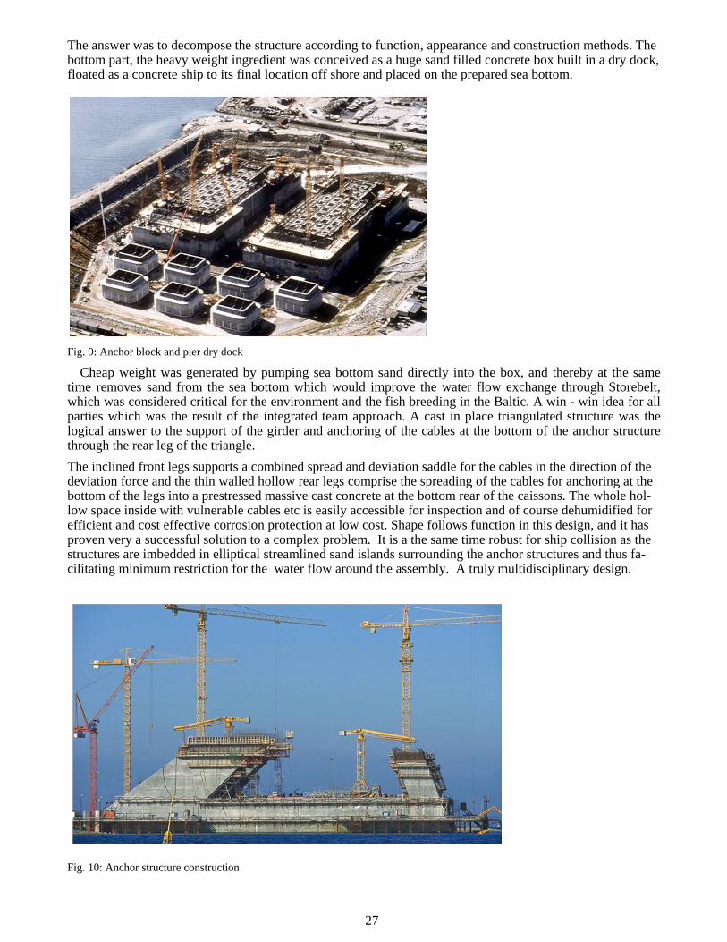
The answer was to decompose the structure according to function, appearance and construction methods. The bottom part, the heavy weight ingredient was conceived as a huge sand filled concrete box built in a dry dock, floated as a concrete ship to its final location off shore and placed on the prepared sea bottom. Fig. 9: Anchor block and pier dry dock
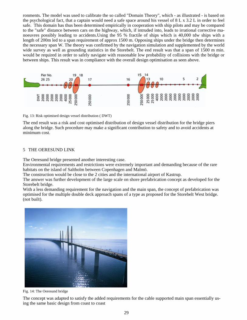
Cheap weight was generated by pumping sea bottom sand directly into the box, and thereby at the same time removes sand from the sea bottom which would improve the water flow exchange through Storebelt, which was considered critical for the environment and the fish breeding in the Baltic. A win - win idea for all parties which was the result of the integrated team approach. A cast in place triangulated structure was the logical answer to the support of the girder and anchoring of the cables at the bottom of the anchor structure through the rear leg of the triangle. The inclined front legs supports a combined spread and deviation saddle for the cables in the direction of the deviation force and the thin walled hollow rear legs comprise the spreading of the cables for anchoring at the bottom of the legs into a prestressed massive cast concrete at the bottom rear of the caissons. The whole hol-low space inside with vulnerable cables etc is easily accessible for inspection and of course dehumidified for efficient and cost effective corrosion protection at low cost. Shape follows function in this design, and it has proven very a successful solution to a complex problem. It is a the same time robust for ship collision as the structures are imbedded in elliptical streamlined sand islands surrounding the anchor structures and thus fa-cilitating minimum restriction for the water flow around the assembly. A truly multidisciplinary design. Fig. 10: Anchor structure construction
28
The determination of optimum navigation span was one of the most challenging and demanding tasks.All parameters were interacting, like international navigation route, cost, construction method, bridge type (sus-pension or cable stayed), the amount of compensating dredging in the sea bottom to maintain the so called 0 solution for the water flow exchange with the Baltic Sea the environment, foundation, aesthetics etc.Because of all these parameters interacting it was interesting to observe the final result which indicated that overall cost for comparable bridge length would be only moderately affected by choice of spans between 900 m and 1700 m approx.
Fig. 11: Storebelt East Bridge - Span optimisation
The increased bridge structure cost for increasing span was largely compensated for by lowered cost for com-pensating dredging, protection reefs for shipping and realignment costs for the navigation channel required for shorter spans.This case was in fact much more complex, but it demonstrates that it is important to have all parameters and experts present and interacting in the decision process and because of well prepared documen-tation - the politicians understood and approved the recommendation. Fig. 12: Navigation Simulation - Domain theory
The most convincing verification for span requirements for safe navigation in the Storebelt was a realistic navigation simulation using experienced qualified pilots under real time simulations in realistic virtual envi-
29
ronments. The model was used to calibrate the so called "Domain Theory", which - as illustrated - is based on the psychological fact, that a captain would need a safe space around his vessel of 8 L x 3.2 L in order to feel safe. This domain has thus been determined empirically in cooperation with ship pilots and may be compared to the "safe" distance between cars on the highway, which, if intruded into, leads to irrational corrective ma-noeuvres possibly leading to accidents.Using the 95 % fractile of ships which is 40,000 tdw ships with a length of 200m led to a span requirement of approx 1500 m. Opposing ships under the bridge then determines the necessary span W. The theory was confirmed by the navigation simulation and supplemented by the world wide survey as well as grounding statistics in the Storebelt. The end result was that a span of 1500 m min. would be required in order to safely navigate with reasonable low probability of collisions with the bridge or between ships. This result was in compliance with the overall design optimisation as seen above.
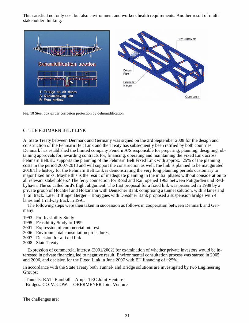
Fig. 13: Risk optimised design vessel distribution ( DWT)
The end result was a risk and cost optimised distribution of design vessel distribution for the bridge piers along the bridge. Such procedure may make a significant contribution to safety and to avoid accidents at minimum cost.
5 THE OERESUND LINK
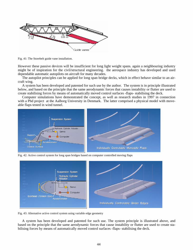
The Oeresund bridge presented another interesting case. Environmental requirements and restrictions were extremely important and demanding because of the rare habitats on the island of Saltholm between Copenhagen and Malmö. The construction would be close to the 2 cities and the international airport of Kastrup. The answer was further development of the large scale on shore prefabrication concept as developed for the Storebelt bridge. With a less demanding requirement for the navigation and the main span, the concept of prefabrication was optimised for the multiple double deck approach spans of a type as proposed for the Storebelt West bridge. (not built). Fig. 14: The Oeresund bridge
The concept was adapted to satisfy the added requirements for the cable supported main span essentially us-ing the same basic design from coast to coast
30
This gave optimum time and costs as well as a pleasing harmonious clean overall solution. Fig. 15: Elevation of Oeresund bridge
An added feature was that the design was tendered on the basis of a preliminary design leaving the option of the contractor optimising the detailed design, fabrication and erection processes. Fig. 16: Svanen at work installing a 8,700 t 144 m bridge span
The end result was a very efficient repetitive process using highly optimised bridge components for prefab of pier caissons, pier shafts and full span superstructure elements with 144 m double deck composite spans. The fabrication, maintenance and aesthetic considerations led to a simple and clean truss configuration with closed box members Fig. 17: Clean closed dehumidified box members
The reason for the closed members was a. o. that the proven and efficient corrosion protection method by de-humidification of the inside could be used.
31
This satisfied not only cost but also environment and workers health requirements. Another result of multi-stakeholder thinking. Fig. 18 Steel box girder corrosion protection by dehumidification
6 THE FEHMARN BELT LINK
A State Treaty between Denmark and Germany was signed on the 3rd September 2008 for the design and construction of the Fehmarn Belt Link and the Treaty has subsequently been ratified by both countries. Denmark has established the limited company Femern A/S responsible for preparing, planning, designing, ob-taining approvals for, awarding contracts for, financing, operating and maintaining the Fixed Link across Fehmarn Belt.EU supports the planning of the Fehmarn Belt Fixed Link with approx. 25% of the planning costs in the period 2007-2013 and will support the construction as well.The link is planned to be inaugurated 2018.The history for the Fehmarn Belt Link is demonstrating the very long planning periods customary to major fixed links. Maybe this is the result of inadequate planning in the initial phases without consideration to all relevant stakeholders? The ferry connection for Road and Rail opened 1963 between Puttgarden und Rød-byhavn. The so called bird's flight alignment. The first proposal for a fixed link was presented in 1988 by a private group of Hochtief and Holzmann with Deutscher Bank comprising a tunnel solution, with 3 lanes and 1 rail track. Later Bilfinger Berger + Bouygues with Dresdner Bank proposed a suspension bridge with 4 lanes and 1 railway track in 1991.
The following steps were then taken in succession as follows in cooperation between Denmark and Ger-many: 1993 Pre-feasibility Study 1995 Feasibility Study to 1999 2001 Expression of commercial interest 2006 Environmental consultation procedures 2007 Decision for a fixed link 2008 State Treaty
Expression of commercial interest (2001/2002) for examination of whether private investors would be in-terested in private financing led to negative result. Environmental consultation process was started in 2005 and 2006, and decision for the Fixed Link in June 2007 with EU financing of ~25%. In accordance with the State Treaty both Tunnel- and Bridge solutions are investigated by two Engineering Groups: - Tunnels: RAT: Rambøll – Arup - TEC Joint Venture - Bridges: COJV: COWI – OBERMEYER Joint Venture The challenges are:
32
- Water flow in the Fehmarnbelt - Navigational safety and operational and construction risk evaluation. - Temporary and permanent environmental effects, in particular water. - Construction period and construction costs
Fig. 19: The Bird's flight corridor with Fehmarn Link
Fig. 20: Rendering of the proposed Fehmarn main spans
Further important basic conditions are: - International navigation channel requiring participation of the IMO (International Maritime Organisation) - Plan approval procedures in Germany - Participation of the Baltic Sea neighbours according to the ESPOO convention - Demands from international agreements such as HELCOM agreement, EIA directive 85/337/EEC. The fixed link shall be designed for a four lane motorway and dual track railway, and the basis of planning is the State Treaty as well as the national laws in Denmark and Germany.
33
- Tender Design is expected to be initiated early 2011. The shipping in the Fehmarn Belt is considerable as appears from estimates made in 1995 and the forecast from the FSA (Formal Safety Assessment) for the so called T Route 2018: 66,000 vessels/year 2038: 105,000 vessels/year Currently 38,000 ferry crossings per year take care of the traffic between Rodby in Denmark and Puttgarten in Germany. Fig. 21: Typical superstructure cross section
The risk of disruption for the link should be comparable to the risk of disruption for the Oeresund Link. The collision design forces have, after a thorough risk analysis along same principles as for Storebelt, been determined as follows for the various piers: - Main Pylons 790 MN - Piers 540 (type I), 185 (type II and III) and 120 (type IV) MN - Deck house collision 44 MN The risks were categorized as per the table below: Fig. 22 Risk categories
A special sacrificial replaceable contained sand filled island concept has been developed in order to protect the piers in case of ship collisions - a result of close cooperation between different disciplines.
34
Fig. 23: Sacrificial contained sand filled pier protection island
The environmental impact assessment, EIA, and development of conceptual design are performed in parallel and in close interaction. In order to optimise environmental impact in an integrated process with the concep-tual design, EIA and development of design interact in a continuous dialogue with open mutual spirit and willingness to incorporate new suggestions. The environment has been valued in order to identify low impact corridors and to compare alternatives in terms of environmental issues. Different alignments (footprint) have been developed and compared by the design teams, for optimum selection.
The impact assessment has started for air quality and climate during construction based on interactive dia-logue between bridge and environmental experts in order to optimise from all points of view in a simultane-ous process. At later stages: incorporation of further mitigation measures, placement of fauna passages, cor-rections of longitudinal profile are planned. The key ingredients in the overall multidisciplinary process are: Legal framework Population Landscape and soil Flora fauna and biodiversity Natura 2000 Cultural heritage Recreation Surface water Groundwater Contaminated soils Energy, raw materials and waste Air and climate Noise and vibration Light Derived socio-economic issues The impacts on the Lollandic dike will be avoided/minimised Valuable for the landscape, flora and fauna, migration, recreation and cultural heritage The low wet flatlands lying behind the dike Sandy and nutrient-poor and therefore valuable for flora and fauna
35
No unneccessary technical installations (toll station, access roads) will be placed in the area – the road/railway will cross on a dam/bridge leaving the surrounding area as untouched as possible and not per-manently drained. Fig. 24: Protected species Habitats for amphibians will be avoided or compensated New water ponds will be established the year before construction starts Barriers for fauna and humans will be minimised Passages will be established crossing the road/railways It is expected that the first construction contract may be signed July 2013 for completion of the Fehmarn Belt Link in 2018.
A major ingredient in the concepts for the 3 major links in Northern Europe is the extended and systematic use of large scale prefabrication. The advantages are tremendous. Safety for workers working at lower level on shore, higher production efficiency, lower cost, better quality and quality control, possibility of replacing unsuccessful elements, much reduced environmental impact, socio-economic advantages because of possibil-ity to plan for off site production where labour market is most advantageous and where unemployment might need stimulation. Fig. 25: Max lifting weights of prefab bridge elements for the Northern European Fixed Links
36
Fig. 26: Floating crane "Svanen" Lifting capacity 8.700 t
7 QATAR - BAHRAIN CAUSEWAY
The Qatar - Bahrain Causeway is 42 km long with a signature bridge for navigation of 250 m and as such the world longest causeway - bridge. A structure that lends itself to mass prefab production. In most respects we were to study a causeway in literally "unchartered water". It was initiated with surveys, site investigations and studies to establish base data. This project was truly multi disciplinary.12 different specialized depart-ments were involved plus specialist assistance from Sund& Baelt and DHI.
Fig. 27: The Qatar-Bahrain Causeway
Fig. 28: Qatar -Bahrain Causeway
37
The studies comprised: Planning Study Traffic Study Topographic Survey Utility Survey Bathymetric and Geophysical Survey Geotechnical Investigations Geotechnical Assessment Durability Study Light Rail and Monorail System Marine Studies Design Basis Environmental & Ecological studies Environmental Impact Assessment
Fig. 29: Alignment selection Fig. 30: Evaluation of alignment and corridors
38
A very comprehensive decision basis model combining the weighted decision attributes was used to select the best alignment in a long process. The advantage is a transparent process with full documentation for the final decision. It is difficult then later on to come back and question the decision if all relevant stakeholders and interested parties beforehand have agreed to the process and method, and the decision basis may be traced by others later.Such methodologies are highly recommended for complex projects in particular in urban areas, as the risk of delays later in the proces is minimized. SMART (Simple Multi Attribute Rating Technique) used in the process.
All stakeholders from both countries were invited to full day workshop in the selectio9n from 10 align-ments to 3 and again later from 3 to 1. Starting with a presentation of basis and options. Open discussion amongst stake holders. Alternative ratings and scoring applied "live".
Environmental consideration was the one issue that played the major role in the very first selection: select-ing of C1 - C4 alignments any crossing the shallow ref (shaded blue on plan, slide 4) would have resulted in cost savings of USD 500 million but would have inflicted significant negative environmental impact. These options were ruled out in the very first alignment workshop by a unanimous decision by all stakeholders. The environmental and engineering teams have been working together in integrated team to identify so-lutions which minimize the adverse effects. Mitigation measures are addressed and implemented in the three main phases of the project: Design (mitigation built into the design), Construction (mitigation of impacts due to construction activities) and Operation (mitigation of permanent impacts).
The most important mitigation measure to be built into the design is the choice of alignment. The second most important is the "zero-solution". The "zero-solution" means, that the amount of water and salt transported in and out of the Bay of Salwa is the same as before construction of the causeway. In other words, the Qatar-Bahrain Causeway works should not change the exchange of water and salt between the Arabian Gulf and the Bay of Salwa. Any blockage of the exchange would cause the salinity in the Bay of Salwa to rise and could result in large scale regional impacts on the marine ecosystem. The criterion of zero-solution is defined within ±0.5%. This concept was originally developed for the construction of the Great Belt Link in Denmark!
Seagrass: Potential impacts during construction: prolonged periods of shading due to suspended sediments in the water and smothering by sedimentation. Mitigation: Minimise sediment spill by introducing bunds around reclamations, optimize dredger operation and use of silt curtains if necessary. Potential impacts during operation: Footprint of permanent embankments, fill deposits and dredging of channels. Possible compensa-tion: create intertidal zone in fill deposits.
Corals: Potential impacts during construction: shading by suspended sediments during dredging and smothering by sedimentation. Mitigation: Minimise sediment spill. Potential impacts during operation: Foot-print of embankments and dredging of channels. Possible compensation: artificial reefs of concrete blocks. The QBC provide new habitats, 32 km of revetments will function as artificial reefs, 2500 bridge piles.
Fish and shrimps: Potential Impacts during construction: Fish avoidance of sediment plumes during con-struction and noise. Potential impacts during operation: dispersal of shrimp larvae from spawning grounds to nursery grounds, permanent loss of fish/shrimp nursery habitats. Mitigation: new habitats on embankment re-vetments and bridge piles. Fig. 31: Key environmental issues - Sea grass, Corals, Fish and Turtles, dugongs and Dolphins
39
Fishery: Potential impacts during construction: fishing prohibited in 500 m safety zone on each side of alignment, affects two fishing areas with the consequence of a temporary loss of income. Potential Impacts during operation: security zone around causeway may be required, affects two fishing areas with the conse-quence of a temporary loss of income and some fishing traps along the coast will be affected too. Mitigation: New habitat 32 km of embankment revetments. Possible compensation: artificial reefs of concrete blocks.
Turtles, Dugongs and Dolphins: Potential impacts during construction: Degradation of foraging habitats, disturbance during migration, feeding and reproduction. Mitigation: awareness training of the construction workers, spotters on construction vessels, responsible sailing behavior, comprehensive monitoring pro-gramme.
The Key for the success of the project was the extreme awareness of the need for environmental considera-tions, which played a major role in selection of the Causeway alignment. Permanent environmental impacts will be reduced with the introduction of the "zero solution".Minimizing sediment spill during construction will reduce environmental impacts.The project will provide new habitats in form of 32 km embankment re-vetments and 2500 bridge piles. Awareness training, spotters on construction vessels and responsible sailing behavior will minimize impacts on turtles, dugongs and dolphins and comprehensive environmental monitor-ing programme before, during and after construction will be implemented.
8 BONGOBONDHU BRIDGE
The Bongobondhu Bridge (Jamuna River Bridge) was made feasible and possible because of a unique combi-nation of technologies reducing cost and environmental impact as well as improving construction efficiency and safety. The purpose of the crossing was to connect the East and West part of Bangladesh separated by one of the longest and most unpredictable rivers with extreme waterflows in the world. Traditional long suspension spans founded on 20-40m dia concrete caissons in the liquefaction prone uni-formly graded sand masses subjected to very deep scour to 80 m depth were cost prohibitive, and abandoned in favour of a light trestle type bridge founded on simple tri pod like foundations utilizing offshore large di-ameter steel piling with bearing capacities up to 10,000 t. This technology proposed by the World Bank Panel of Experts more than halved the cost from 1 bUS$ to 500 mUS$ approx. and made the project financially vi-able.
9 ENVIRONMENTALLY FRIENDLY AND HEALTHY CABLE CORROSION PROTECTION
Corrosion of suspension cables and cable stays has become an increasing concern over the years caused by a substantial amount of bad experiences. Galvanizing alone is insufficient in particular for cables which are vir-tually non-replaceable. Fig. 32: 83 m long 3.15 m Dia driven steel piles grouted at bottom with conical prefab pile caps
40
The double cantilevered superstructure box girders were mass produced by prefabrication and installed on the conical prefabricated pier caps for low cost, and high quality with minimum environmental impact.
The answer to this is corrosion protection also of cables by the most efficient means known: by dry air pre-venting water from contact with the steel. The efficiency of the dehumidification blowing dry air through the cable voids between wires is convincing as it has been proven for steel box girders since the first application in the Lillebaelt suspension bridge in Denmark in the late 1960'ies.
And it is environmentally friendly because it uses very little energy and no adverse emissions. Further it minimises the use of toxic paint systems thereby improving occupational safety of the workers. The condi-tion supervised by continuous monitoring and the resulting life cycle cost is much lower, than for paint sys-tems, possibly approx. 50 - 80% lower. It is suited for new bridges as well as a retrofit to existing bridges with either parallel wires or strands.
The Lillebaelt Bridge, built in the late 1960’ ies and the first with internal box girder dehumidification in the world, has been retrofitted with a cable dehumidification system as indicated on the above fig. The effi-ciency is demonstrated by the lowering of cable air humidity from average 70% to average 45%, where no corrosion occurs.The system, first time used for the Akashi Strait bridge in Japan, now is universally applied globally to all new major bridges. The Hoga Kusten bridge in northern Sweden with 1210 m main span is fea-turing one of the first applications in Europe. The bridge is the northern most large suspension bridge in the world with its 1210 m main span.
41
Fig. 35: Lillebaelt Bridge. Retrofitted main cable dehumidification system.
Fig. 36: Hoga Kusten Bridge, Sweden, with dehumidified box girder and main cables
10 NEW MATERIALS FOR BRIDGES?
Traditional materials concrete and steel for bridges has been around for centuries. Other industries have gradually over the years replaced steel by newer lighter and more efficient materials like high alloy alumin-ium and most recently glass- and carbon fiber composites. One of the most promising future materials for
42
long span bridges is carbon fibres composites, CFRP or similar. They have a wide usage in the automotive industry, aerospace industry, wind mill wings, as well as consumer goods like skis, tennis rackets, etc. etc. For the civil engineering structures applications have been very limited, and mostly for strengthening of exist-ing bridges with epoxy glued carbon fiber elements. The limited use is of course due to high cost compared to more traditional materials. However we need to constantly strive for development and innovation in our work. We may take inspiration from our colleagues in other industries, and learn from their developments and experiences. Innovation most often takes place at the borderlines and at interfaces between technologies. With the increasing spans of the future we need to get used to new more efficient materials than steel and concrete. The Carbon fibres have a much improved strength/weight ratio over steel which will make them at-tractive for cables and reinforcement in the future.
In order to gain experience with design, construction and durability under realistic environments a pedes-trian bridge in Denmark was selected as research project by the Danish road directorate in 1998. The bridge was equipped with carbon fibre cables, carbon fibre post tensioning cables and non- tensioned reinforcement in the concrete bridge deck. Fig. 37: The Herning pedestrian bridge with carbon fibre stays
We now have 12 years experience in service of this bridge, and all inspections to date have revealed perfect operation with no deteoriation or unexpected issues whatsoever.
Fig. 38: The bridge under construction
43
This is an excellent basis for taking the next step with application of the new materials. It is expected that prices will come down so we can take advantage of the excellent strength/weight ratio for long span cable stayed or suspension bridges. Their application will open for a whole new interesting development for super long span and very light bridges like the Messina, Djibouti-Yemen and Gibraltar bridges in the future. They will then demand more attention to deflection and aerodynamic stability. Fig. 39: The Messina Bridge
11 ACTIVE CONTROL FOR LONG SPAN BRIDGES.
No doubt the future use of modern new materials with low weight and high strength will lead to structures which will be lively subjected to user's loads and aerodynamic forces. the structures will in many ways behave like aircraft and aerodynamically induced movements or even instability might occur.
In the past passive stabilisation devices essentially improving the airflow over the bridge girder have been used - inspired by the aircraft industry.
One such first application was for the Lillebaelt suspension bridge in Denmark in the late 1960'ies. The in-stallation of wind flow deflecting surfaces -guide vanes- similar to aircraft slats- on the top of the girder re-sulted in lower turbulence content in the passing air flow and improved aerodynamic stability.
Fig 40: the littlebelt bridge, denmark with aerodynamic flow improving slats Later a similar system of guide vanes was installed on the storebelt suspension bridge deck lower edges of the box after low frequency oscillations were realised during construction. They have proven very effective as well.
44
Fig. 41: The Storebelt guide vane installation. However these passive devices will be insufficient for long light weight spans. again a neighbouring industry might be of inspiration for the civil/structural engineering. the aerospace industry has developed and used dependable automatic autopilots on aircraft for many decades.
The autopilot principles can be applied for long span bridge decks, which in effect behave similar to an air-craft wing.
A system has been developed and patented for such use by the author. The system is in principle illustrated below, and based on the principle that the same aerodynamic forces that causes instability or flutter are used to create stabilising forces by means of automatically moved control surfaces -flaps- stabilising the deck.
Computer simulations have demonstrated the concept, as well as research studies in 1997 in connection with a Phd project at the Aalborg University in Denmark. The latter comprised a physical model with move-able flaps tested in wind tunnel.
1
2
Fig. 42: Active control system for long span bridges based on computer controlled moving flaps
Fig. 43: Alternative active control system using variable edge geometry A system has been developed and patented for such use. The system principle is illustrated above, and
based on the principle that the same aerodynamic forces that cause instability or flutter are used to create sta-bilising forces by means of automatically moved control surfaces -flaps- stabilising the deck.
45
Adequate reliability to a level normally used in civil engineering structures can be achieved by installa-tions of several completely independent systems along the edge of the girder, in such a way that partial fail-ures of certain systems does not affect the other systems. Thus any desired reliability can be achieved.
12. CONCLUSIONS
I have tried with this quick overview to document the enormous potential for designing even better bridges by adopting the multidisciplinary approach.
We need more innovation in the active dialogue between the many experts and designers and constructor's, as well as the bridge owners.
Innovation does not come by it self. It does not come by asking somebody to innovate as a working order. It happens if you are inspired in the right working environment.
We can simply not avoid generating new ideas and innovations in a creative enthusiastic and dynamic and inspirational environment involving all relevant interested parties and stake holders in an open and transpar-ent process. It has been proven, and it will happen again. Who would not like to be part of this?


![PROGRAM - iabse 2017 COLUMBIA (SEABC) IABSE ... 1_mb1-tl ;; m]f obmvl ;l0;uv71 ott;-] ;v- m7= ub;m7v7 7 ubm]- = ; b m|;mv;7 - vo =t ; ... ScientiÞc Program ...](https://static.documents.pub/doc/80x56/5abbd3807f8b9a441d8d4177/program-iabse-2017-columbia-seabc-iabse-1mb1-tl-mf-obmvl-l0uv71-ott-.jpg)


![02-Hålogalandsbrua IABSE Denmark Mini-seminar 2013.Ppt [Read-Only] [Compatibility Mode]](https://static.documents.pub/doc/80x56/577cc7861a28aba711a13651/02-halogalandsbrua-iabse-denmark-mini-seminar-2013ppt-read-only-compatibility.jpg)


