67
IAEA SAFETY STANDARDS SERIES Seismic Design and Qualification for Nuclear Power Plants SAFETY GUIDE No. NS-G-1.6
| Date post: | 29-Oct-2015 |
| Category: |
Documents |
| Upload: | vicky-gautam |
| View: | 45 times |
| Download: | 0 times |

IAEASAFETY
STANDARDSSERIES
Seismic Design and Qualification forNuclear Power Plants
SAFETY GUIDENo. NS-G-1.6

IAEA SAFETY RELATED PUBLICATIONS
IAEA SAFETY STANDARDS
Under the terms of Article III of its Statute, the IAEA is authorized to establish standardsof safety for protection against ionizing radiation and to provide for the application of thesestandards to peaceful nuclear activities.
The regulatory related publications by means of which the IAEA establishes safetystandards and measures are issued in the IAEA Safety Standards Series. This series coversnuclear safety, radiation safety, transport safety and waste safety, and also general safety (thatis, of relevance in two or more of the four areas), and the categories within it are SafetyFundamentals, Safety Requirements and Safety Guides.
Safety Fundamentals (blue lettering) present basic objectives, concepts and principles ofsafety and protection in the development and application of nuclear energy for peacefulpurposes.
Safety Requirements (red lettering) establish the requirements that must be met to ensuresafety. These requirements, which are expressed as ‘shall’ statements, are governed bythe objectives and principles presented in the Safety Fundamentals.
Safety Guides (green lettering) recommend actions, conditions or procedures for meetingsafety requirements. Recommendations in Safety Guides are expressed as ‘should’ state-ments, with the implication that it is necessary to take the measures recommended orequivalent alternative measures to comply with the requirements.
The IAEA’s safety standards are not legally binding on Member States but may beadopted by them, at their own discretion, for use in national regulations in respect of their ownactivities. The standards are binding on the IAEA in relation to its own operations and on Statesin relation to operations assisted by the IAEA.
Information on the IAEA’s safety standards programme (including editions in languagesother than English) is available at the IAEA Internet site
www-ns.iaea.org/standards/or on request to the Safety Co-ordination Section, IAEA, P.O. Box 100, A-1400 Vienna,Austria.
OTHER SAFETY RELATED PUBLICATIONS
Under the terms of Articles III and VIII.C of its Statute, the IAEA makes available andfosters the exchange of information relating to peaceful nuclear activities and serves as anintermediary among its Member States for this purpose.
Reports on safety and protection in nuclear activities are issued in other series, inparticular the IAEA Safety Reports Series, as informational publications. Safety Reports maydescribe good practices and give practical examples and detailed methods that can be used tomeet safety requirements. They do not establish requirements or make recommendations.
Other IAEA series that include safety related publications are the Technical ReportsSeries, the Radiological Assessment Reports Series, the INSAG Series, the TECDOCSeries, the Provisional Safety Standards Series, the Training Course Series, the IAEAServices Series and the Computer Manual Series, and Practical Radiation Safety Manualsand Practical Radiation Technical Manuals. The IAEA also issues reports on radiologicalaccidents and other special publications.

SEISMIC DESIGN AND QUALIFICATION FORNUCLEAR POWER PLANTS

The following States are Members of the International Atomic Energy Agency:
AFGHANISTANALBANIAALGERIAANGOLAARGENTINAARMENIAAUSTRALIAAUSTRIAAZERBAIJANBANGLADESHBELARUSBELGIUMBENINBOLIVIABOSNIA AND
HERZEGOVINABOTSWANABRAZILBULGARIABURKINA FASOCAMEROONCANADACENTRAL AFRICAN
REPUBLICCHILECHINACOLOMBIACOSTA RICACÔTE D’IVOIRECROATIACUBACYPRUSCZECH REPUBLICDEMOCRATIC REPUBLIC
OF THE CONGODENMARKDOMINICAN REPUBLICECUADOREGYPTEL SALVADORERITREAESTONIAETHIOPIAFINLANDFRANCEGABONGEORGIAGERMANYGHANA
GREECEGUATEMALAHAITIHOLY SEEHONDURASHUNGARYICELANDINDIAINDONESIAIRAN, ISLAMIC REPUBLIC OF IRAQIRELANDISRAELITALYJAMAICAJAPANJORDANKAZAKHSTANKENYAKOREA, REPUBLIC OFKUWAITKYRGYZSTANLATVIALEBANONLIBERIALIBYAN ARAB JAMAHIRIYALIECHTENSTEINLITHUANIALUXEMBOURGMADAGASCARMALAYSIAMALIMALTAMARSHALL ISLANDSMAURITIUSMEXICOMONACOMONGOLIAMOROCCOMYANMARNAMIBIANETHERLANDSNEW ZEALANDNICARAGUANIGERNIGERIANORWAYPAKISTANPANAMA
PARAGUAYPERUPHILIPPINESPOLANDPORTUGALQATARREPUBLIC OF MOLDOVAROMANIARUSSIAN FEDERATIONSAUDI ARABIASENEGALSERBIA AND MONTENEGROSEYCHELLESSIERRA LEONESINGAPORESLOVAKIASLOVENIASOUTH AFRICASPAINSRI LANKASUDANSWEDENSWITZERLANDSYRIAN ARAB REPUBLICTAJIKISTANTHAILANDTHE FORMER YUGOSLAV
REPUBLIC OF MACEDONIATUNISIATURKEYUGANDAUKRAINEUNITED ARAB EMIRATESUNITED KINGDOM OF
GREAT BRITAIN AND NORTHERN IRELAND
UNITED REPUBLICOF TANZANIA
UNITED STATES OF AMERICAURUGUAYUZBEKISTANVENEZUELAVIETNAMYEMENZAMBIAZIMBABWE
The Agency’s Statute was approved on 23 October 1956 by the Conference on the Statuteof the IAEA held at United Nations Headquarters, New York; it entered into force on 29 July 1957.The Headquarters of the Agency are situated in Vienna. Its principal objective is “to accelerate andenlarge the contribution of atomic energy to peace, health and prosperity throughout the world’’.
© IAEA, 2003
Permission to reproduce or translate the information contained in this publication may beobtained by writing to the International Atomic Energy Agency, Wagramer Strasse 5, P.O. Box 100,A-1400 Vienna, Austria.
Printed by the IAEA in AustriaNovember 2003STI/PUB/1158

SAFETY STANDARDS SERIES No. NS-G-1.6
SEISMIC DESIGN AND QUALIFICATION FORNUCLEAR POWER PLANTS
SAFETY GUIDE
INTERNATIONAL ATOMIC ENERGY AGENCYVIENNA, 2003

IAEA Library Cataloguing in Publication Data
Seismic design and qualification for nuclear power plants : safety guide. —Vienna : International Atomic Energy Agency, 2003.
p. ; 24 cm. — (Safety standards series, ISSN 1020–525X ;no. NS-G-1.6)
STI/PUB/1158ISBN 92–0–110703–XIncludes bibliographical references.
1. Nuclear reactors — Safety measures. 2. Earthquake resistantdesign. 3. Nuclear power plants. I. International Atomic Energy Agency.II. Series.
IAEAL 03–00335

FOREWORD
by Mohamed ElBaradeiDirector General
One of the statutory functions of the IAEA is to establish or adoptstandards of safety for the protection of health, life and property in thedevelopment and application of nuclear energy for peaceful purposes, and toprovide for the application of these standards to its own operations as well as toassisted operations and, at the request of the parties, to operations under anybilateral or multilateral arrangement, or, at the request of a State, to any of thatState’s activities in the field of nuclear energy.
The following bodies oversee the development of safety standards: theCommission on Safety Standards (CSS); the Nuclear Safety StandardsCommittee (NUSSC); the Radiation Safety Standards Committee (RASSC);the Transport Safety Standards Committee (TRANSSC); and the Waste SafetyStandards Committee (WASSC). Member States are widely represented onthese committees.
In order to ensure the broadest international consensus, safety standardsare also submitted to all Member States for comment before approval by theIAEA Board of Governors (for Safety Fundamentals and SafetyRequirements) or, on behalf of the Director General, by the PublicationsCommittee (for Safety Guides).
The IAEA’s safety standards are not legally binding on Member Statesbut may be adopted by them, at their own discretion, for use in nationalregulations in respect of their own activities. The standards are binding on theIAEA in relation to its own operations and on States in relation to operationsassisted by the IAEA. Any State wishing to enter into an agreement with theIAEA for its assistance in connection with the siting, design, construction,commissioning, operation or decommissioning of a nuclear facility or any otheractivities will be required to follow those parts of the safety standards thatpertain to the activities to be covered by the agreement. However, it should berecalled that the final decisions and legal responsibilities in any licensingprocedures rest with the States.
Although the safety standards establish an essential basis for safety, theincorporation of more detailed requirements, in accordance with nationalpractice, may also be necessary. Moreover, there will generally be specialaspects that need to be assessed on a case by case basis.
The physical protection of fissile and radioactive materials and of nuclearpower plants as a whole is mentioned where appropriate but is not treated in

detail; obligations of States in this respect should be addressed on the basis ofthe relevant instruments and publications developed under the auspices of theIAEA. Non-radiological aspects of industrial safety and environmentalprotection are also not explicitly considered; it is recognized that States shouldfulfil their international undertakings and obligations in relation to these.
The requirements and recommendations set forth in the IAEA safetystandards might not be fully satisfied by some facilities built to earlierstandards. Decisions on the way in which the safety standards are applied tosuch facilities will be taken by individual States.
The attention of States is drawn to the fact that the safety standards of theIAEA, while not legally binding, are developed with the aim of ensuring thatthe peaceful uses of nuclear energy and of radioactive materials are undertakenin a manner that enables States to meet their obligations under generallyaccepted principles of international law and rules such as those relating toenvironmental protection. According to one such general principle, theterritory of a State must not be used in such a way as to cause damage inanother State. States thus have an obligation of diligence and standard of care.
Civil nuclear activities conducted within the jurisdiction of States are, asany other activities, subject to obligations to which States may subscribe underinternational conventions, in addition to generally accepted principles ofinternational law. States are expected to adopt within their national legalsystems such legislation (including regulations) and other standards andmeasures as may be necessary to fulfil all of their international obligationseffectively.
EDITORIAL NOTE
An appendix, when included, is considered to form an integral part of the standardand to have the same status as the main text. Annexes, footnotes and bibliographies, ifincluded, are used to provide additional information or practical examples that might behelpful to the user.
The safety standards use the form ‘shall’ in making statements about requirements,responsibilities and obligations. Use of the form ‘should’ denotes recommendations of adesired option.
The English version of the text is the authoritative version.
CONTENTS
1. INTRODUCTION . . . . . . . . . . . . . . . . . . . . . . . . . . . . . . . . . . . . . . . . . 1
Background (1.1–1.5) . . . . . . . . . . . . . . . . . . . . . . . . . . . . . . . . . . . . . . . 1Objective (1.6) . . . . . . . . . . . . . . . . . . . . . . . . . . . . . . . . . . . . . . . . . . . . . 2Scope (1.7–1.12) . . . . . . . . . . . . . . . . . . . . . . . . . . . . . . . . . . . . . . . . . . . . 2Structure (1.13) . . . . . . . . . . . . . . . . . . . . . . . . . . . . . . . . . . . . . . . . . . . . 3
2. GENERAL SAFETY CONCEPTS . . . . . . . . . . . . . . . . . . . . . . . . . . . 4
Scope (2.1–2.2) . . . . . . . . . . . . . . . . . . . . . . . . . . . . . . . . . . . . . . . . . . . . . 4Design basis earthquake (2.3–2.10) . . . . . . . . . . . . . . . . . . . . . . . . . . . . 4Seismic categorization for structures, systems
and components (2.11–2.26) . . . . . . . . . . . . . . . . . . . . . . . . . . . . . . . . 6Combination of earthquake loads with operating
condition loads (2.27–2.30) . . . . . . . . . . . . . . . . . . . . . . . . . . . . . . . . . 10Seismic capacity (2.31–2.38) . . . . . . . . . . . . . . . . . . . . . . . . . . . . . . . . . . 12Considerations for beyond design basis events (2.39–2.40) . . . . . . . . 14Content of the safety analysis report (2.41) . . . . . . . . . . . . . . . . . . . . . 15
3. SEISMIC DESIGN . . . . . . . . . . . . . . . . . . . . . . . . . . . . . . . . . . . . . . . . . 15
Selection of an appropriate plant layout (3.1–3.5) . . . . . . . . . . . . . . . 15Geotechnical parameters (3.6) . . . . . . . . . . . . . . . . . . . . . . . . . . . . . . . . 16Civil engineering structures (3.7) . . . . . . . . . . . . . . . . . . . . . . . . . . . . . . 16Earth structures (3.8–3.10) . . . . . . . . . . . . . . . . . . . . . . . . . . . . . . . . . . . 18Piping and equipment (3.11–3.13) . . . . . . . . . . . . . . . . . . . . . . . . . . . . . 19Selection of appropriate design standards (3.14–3.17) . . . . . . . . . . . . 20Periodic safety review (3.18–3.20) . . . . . . . . . . . . . . . . . . . . . . . . . . . . . 21
4. GENERALITIES ON SEISMIC QUALIFICATION (4.1–4.10) . . 22
5. QUALIFICATION BY ANALYSIS . . . . . . . . . . . . . . . . . . . . . . . . . . . 25
Modelling techniques (5.1–5.39) . . . . . . . . . . . . . . . . . . . . . . . . . . . . . . 25
Analytical techniques (5.40–5.57) . . . . . . . . . . . . . . . . . . . . . . . . . . . . . 34
6. SEISMIC QUALIFICATION BY MEANS OF TESTING,EARTHQUAKE EXPERIENCE AND INDIRECT METHODS . . . . . . . . . . . . . . . . . . . . . . . . . . . . . . . . . . . . 37
Seismic qualification by means of testing (6.1–6.28) . . . . . . . . . . . . . . 37Seismic qualification by means of
earthquake experience (6.29–6.31) . . . . . . . . . . . . . . . . . . . . . . . . . . 43Seismic qualification by means of indirect methods (6.32–6.37) . . . . 44
7. SEISMIC INSTRUMENTATION . . . . . . . . . . . . . . . . . . . . . . . . . . . . 45
Introduction (7.1–7.3) . . . . . . . . . . . . . . . . . . . . . . . . . . . . . . . . . . . . . . . 45Seismic structural monitoring (7.4–7.5) . . . . . . . . . . . . . . . . . . . . . . . . 46Seismic monitoring and automatic scram systems (7.6–7.10) . . . . . . 46Data processing (7.11–7.13) . . . . . . . . . . . . . . . . . . . . . . . . . . . . . . . . . . 48Post-earthquake actions (7.14–7.19) . . . . . . . . . . . . . . . . . . . . . . . . . . . 48
APPENDIX: SAMPLES OF SEISMIC CATEGORIZATION . . . . . . . . 51
REFERENCES . . . . . . . . . . . . . . . . . . . . . . . . . . . . . . . . . . . . . . . . . . . . . . . . . 53CONTRIBUTORS TO DRAFTING AND REVIEW . . . . . . . . . . . . . . . . 55BODIES FOR THE ENDORSEMENT OF SAFETY STANDARDS . . 57
1 INTERNATIONAL ATOMIC ENERGY AGENCY, Seismic Design andQualification for Nuclear Power Plants, Safety Series No. 50-SG-D15, IAEA, Vienna(1992).
2 INTERNATIONAL ATOMIC ENERGY AGENCY, Seismic Analysis andTesting of Nuclear Power Plants, Safety Series No. 50-SG-S2, IAEA, Vienna (1979).
3 Reference [2] supersedes INTERNATIONAL ATOMIC ENERGY AGENCY,Earthquakes and Associated Topics in Relation to Nuclear Power Plant Siting, SafetySeries No. 50-SG-S1 (Rev.1), IAEA, Vienna (1991).
1. INTRODUCTION
BACKGROUND
1.1. This Safety Guide was prepared under the IAEA’s programme for safetystandards for nuclear power plants. It supplements the Safety Requirementspublication on Safety of Nuclear Power Plants: Design [1].
1.2. The present Safety Guide supersedes the Safety Guide on Seismic Designand Qualification for Nuclear Power Plants issued in 1992.1 A Safety Guide onseismic design was originally issued in 1979 as Safety Series No. 50-SG-S22,which extended the seismic considerations in relation to the siting of nuclearpower plants into the areas of design and qualification. The present SafetyGuide on seismic design makes reference to a Safety Guide [2]3 which givesguidance on how to determine the seismic hazard for a nuclear power plantat a given site.
1.3. The Safety Guide on Seismic Design and Qualification for Nuclear PowerPlants issued in 19921 was revised in 1999–2000 to incorporate newrecommendations arising from recent operational experience, the analysis ofdamage caused to industrial facilities by recent earthquakes, and new scientificevidence on analytical approaches and their reliability. The text was alsorevised for compatibility with other revised Safety Guides [2, 3] as aconsequence of a reorganization of the coverage of hazard evaluation issuesand design issues (for foundations and superstructure).
1.4. Other Safety Guides that support the Safety Requirements publicationon Safety of Nuclear Power Plants: Design [1] present recommendations inrelation to external events and to this extent are complementary to the presentSafety Guide. In particular, since Ref. [4] deals with general procedures fordesign against external events, the present Safety Guide is intended to present
1
a more specific instance of that more general approach, which should beconsidered a reference framework for safety aspects. Reference [3] deals withthe design of foundations and presents recommendations and guidance on theevaluation of the effects of soil–structure interactions and soil liquefaction.
1.5. Other Safety Guides present recommendations relating to theearthquake scenario, but in the framework of the design of specific plantsystems: Ref. [5] deals with the reactor coolant system, Ref. [6] with thecontainment system, Ref. [7] with the emergency power system, and Ref. [8]with instrumentation and control systems.
OBJECTIVE
1.6. The purpose of this Safety Guide is to provide recommendations on agenerally accepted way to design a nuclear power plant so that an earthquakemotion at the site determined according to Ref. [2] will not jeopardize thesafety of the plant. It also gives guidance on a consistent application of methodsand procedures for analysis, testing and qualification of structures andequipment so that they meet the safety requirements established in Ref. [1].Reference [1] covers the design of nuclear power plants, safety assessments forthe design and the regulatory issues concerned with the licensing of plants.
SCOPE
1.7. This Safety Guide is applicable to the design of land based stationarynuclear power plants with water cooled reactors to withstand site specificearthquakes regardless of the severity of the earthquake ground motion or therisk posed to individual plant items, provided that the recommendations ofRef. [2] concerning site exclusion criteria in relation to the hazard are met.
1.8. It is recognized that simplified procedures may be available for some ofthe recommended methods of design and verification. The adequacy of suchprocedures for achieving the safety objective should be determined for theindividual circumstances and should be adequately evaluated in terms of safety.
1.9. It is recognized also that there is generally more than one possibleengineering solution to a problem, and the approach adopted for one nuclearpower plant may result in significant differences in design between that plantand another plant for which a different approach has been adopted.
2
The present Safety Guide is based on the general practices in Member States.A recommended framework for the assessment of seismic safety in plantdesign is presented in Ref. [9].
1.10. Probabilistic assessment of the seismic capacity of a nuclear power plantis beyond the scope of this Safety Guide. Relevant requirements andrecommendations are presented in Refs [1, 9]. This Safety Guide is intended tobe applied to the design and construction of new nuclear power plants and ingeneral it should not be applied in the seismic re-evaluation of existing plants.The assessment of the seismic margin of an existing plant is beyond the scopeof this Safety Guide; such an assessment should follow the generic proceduresoutlined in Ref. [10].
1.11. The recommendations of this Safety Guide may also be applied to reactortypes other than water cooled reactors in stationary nuclear power plants.However, engineering judgement should be used to assess their applicability, inaccordance with the specific safety objectives defined for the plant type concerned.
1.12. The technical recommendations in this Safety Guide concerningmodelling and item qualification may also be applicable in part to the design ofthe plant against vibrational phenomena induced by sources other thanearthquakes, such as explosions in industrial facilities, aircraft crashes,explosions in quarries or accidents with high speed rotating machinery [4].However, such an extension should be done with care and engineeringjudgement should be used, particularly in relation to the frequency of theinduced vibration, its duration, its direction and the mechanism of its impact onthe plant. It should also be noted that the design to resist such loads may takedifferent forms, such as sacrificial walls, or may encompass different failuremodes, such as scabbing or spalling for impact loads. These particularengineering provisions are not considered in this Safety Guide.
STRUCTURE
1.13. Section 2 discusses the safety implications of the design process and therelevant acceptance criteria required for different safety classes. In Section 3the design principles for the achievement of the protection objective arerecommended and the concept of periodic safety review is discussed in relationto the design issues. Guidance on an appropriate selection of methods forseismic qualification is provided in Section 4, recommendations forqualification by analysis are provided in Section 5, and qualification by test and
3
4 In some States, SL-2 corresponds to a level with a probability of being exceededin the range 1 ¥ 10–3 to 1 ¥ 10–4 (mean values) or 1 ¥ 10–4 to 1 ¥ 10–5 (median) per reactorper year and SL-1 corresponds to a level with a probability of being exceeded of 1 ¥ 10–2 (mean value) per reactor per year.
experience is discussed in Section 6. Section 7 presents guidance onrecommended seismic instrumentation, and suitable monitoring proceduresand their relation to design assumptions.
2. GENERAL SAFETY CONCEPTS
SCOPE
2.1. This section makes recommendations on categorizing the structures,systems and components (SSCs) of a nuclear power plant in terms of theirimportance to safety in the event of a design basis earthquake, in accordancewith the requirements established in Safety of Nuclear Power Plants: Design[1]. Recommendations are also made concerning the application of standardsfor design to guarantee an appropriate safety margin in the design.
2.2. A quality assurance programme is required to be established andimplemented to cover items, services and processes that affect safety and arewithin the scope of this Safety Guide (Ref. [1], paras 3.14–3.16). The qualityassurance programme is required to be implemented to ensure that datacollection, data processing, studies, analyses and qualification, code validation(software) and verification, and other activities necessary to meet therecommendations of this Safety Guide are performed correctly [11, 12].
DESIGN BASIS EARTHQUAKE
2.3. According to Ref. [2], two levels of ground motion hazard should beevaluated for each plant sited in a seismic area. Both hazard levels shouldgenerate a number of design basis earthquakes grouped into two series, seismiclevel 1 (SL-1) and seismic level 2 (SL-2), following the procedures outlined inRef. [2] and according to the target probability levels defined for the plantdesign4.
4
5 This level corresponds to an earthquake level often denoted as a safe shutdownearthquake. The term design basis earthquake is sometimes used to refer to a standardor unified safe shutdown earthquake that is site independent.
6 See Ref. [13] for a general discussion on operating limits and conditions andtheir correlation with design safety.
7 In some States some items are still designed with reference to both an SL-2 anda lower level hazard, often termed the operating base earthquake. However, in thisSafety Guide operational requirements are not established together with safetyrequirements as they relate to different objectives. The SL-1 (or the operating baseearthquake) is addressed in this Safety Guide only in relation to its application in safe-ty analysis and design.
2.4 In the plant design SL-25 is associated with the most stringent safetyrequirements, while SL-1 corresponds to a less severe, more probableearthquake level that normally has different safety implications. In general, SL-1 is used for load combinations (when, for reasons related to probabilities,other events are combined with an earthquake at lower intensity), post-accident inspection and national licensing requirements6. For low levels ofseismic hazard, SL-1 is usually not associated with safety requirements but isrelated to operational requirements only. Safety classified items should bedesigned with reference to either SL-1 or SL-2 according to their safetyfunction (usually associated with SL-2) and to operational requirements foroperability or licensing, for example7 (usually associated with SL-1).
2.5. Where a deterministic approach has been selected for the hazardevaluation or directly for the design basis specification, an estimation of theassociated return period should be made, at least to allow a comparison withnational standards for the design of industrial facilities. This value should thenbe assessed in the safety assessment phase, as recommended in Ref. [9].
2.6. It is common practice to have more than one design basis earthquakeassociated with each hazard level, SL-1 and SL-2, each one representative of apotential seismogenic area. All of these should be considered in the design, andappropriate enveloping should be carried out on the results.
2.7. Regardless of the exposure to seismic hazard, an SL-2 design basisearthquakes should be adopted for every nuclear power plant for the design ofsafety classified items. The minimum level should correspond to a peak groundacceleration of 0.1g (zero period of the design response spectrum), to beconsidered at the free field. A unified, site compatible spectrum should beassociated with this peak ground acceleration value. In this case SL-1 may beassumed to be coincident with SL-2.
5
2.8. The design basis earthquake for any hazard level should be defined withaccount taken of the frequency distribution of the potential associatedground motions, their duration and their power spectral density. Particularcare should be taken when two or more sources are identified as majorcontributors to the hazard. In this case enveloping for different groundmotions (or response spectra) originated by different physical mechanisms(e.g. far field and near field mechanisms) associated with the same hazardlevel should be performed with care. Owing to the potential differences inseismic demands on SSCs, it may be appropriate to perform a separatecapacity evaluation for the different ground motions.
2.9. Seismic input motion is normally defined in the free field, at the surfaceof the ground or on the bedrock [2]. Seismic input can be defined in terms ofspectral acceleration, velocity or displacement as a function of the frequency ofground motion.
2.10. When the seismic input is needed for the foundation level, adeconvolution–convolution process may be required for its evaluation, asexplained in Ref. [3].
SEISMIC CATEGORIZATION FOR STRUCTURES, SYSTEMS AND COMPONENTS
2.11. Any major effects to be expected at a site from an earthquake would berelated to the vibrations induced in the SSCs through the structures of theplant. Vibrations can affect the plant safety functions directly or by indirectinteraction mechanisms such as mechanical interaction between items,release of hazardous substances, fire or flooding induced by an earthquake,impairment of operator access and unavailability of evacuation routes oraccess routes.
2.12. All items experience any seismic loading that occurs, and theperformance required in the event of an earthquake is not necessarily relatedto the reference safety function considered in the safety classification (Ref. [1], paras 5.1 and 5.2), which is based on the most demanding of all thesafety functions required by all the design basis conditions (postulatedinitiating events). For a safety oriented approach to design, therefore, inaddition to the safety classification, SSCs may be grouped into four or morecategories in terms of their importance to safety during and after anearthquake.
6
8 Seismic categorization is the process by which a plant item is assigned to a seismiccategory in accordance with its required performance during and after an earthquake, inaddition to other classifications such as safety, quality assurance and maintenance classifi-cations. The relevant acceptance criterion associated with the item is part of thecategorization.
9 In the framework of the defence in depth approach, protection against allexternal events is part of level 1 of defence in depth.
2.13. In the event that an external event categorization is available, as definedin Ref. [4], the seismic categorization8 as proposed here should be consistentwith it. However, a seismic categorization should also be defined in the absenceof a general external event classification, owing to the peculiarity of the seismicdesign, and the seismic categorization is therefore redefined here. Otherclassification methods would be acceptable provided that they met the sameacceptance criteria as defined below.
2.14. A seismic category 1 should be established for the plant. Items in thiscategory should be designed to withstand the consequences of ground motionsassociated with earthquakes of level SL-2. Seismic category 1 usually coincideswith the highest categories identified for safety and covers all items importantto safety. In particular, seismic category 1 should include the following items aswell as all the structures that support them:
(a) Items whose failure could directly or indirectly cause accident conditionsas a consequence of an earthquake of level SL-2;
(b) Items required for shutting down the reactor, maintaining the reactor ina shutdown condition, removing residual heat over the required periodand monitoring parameters essential to these functions;
(c) Items that are required to prevent or mitigate non-permissibleradioactive releases (limits for which should be established by theregulatory body) in the event of any postulated initiating eventsconsidered in the design, regardless of their probability of occurrence.
2.15. The selection of items under item (c) above is related to the defence indepth approach: in the event of an earthquake of level SL-2, all levels of defenceare required to be available at all times (Ref. [1], para. 4.4)9.The physical barriersdesigned to protect the plant from external events other than seismic eventsshould maintain their integrity and functionality during an earthquake.
7
10 In this context, the safety margin is the result of special provisions in design,material selection, construction, maintenance and quality assurance.
11 Acceptance criteria are specified bounds on the value of a functional or condi-tion indicator used to assess the ability of a structure, system or component to performits design function. Acceptance criteria as used here means specified bounds on thevalue of a functional or condition indicator for a structure, system or component in adefined postulated initiating event (e.g. an indicator relating to functionality, leaktight-ness or non-interaction).
2.16. Nuclear power plant items of seismic category 1 should be designed,installed and maintained in accordance with the most stringent nationalpractices for nuclear applications: the safety margin10 should be higher than thesafety margin used in facilities at conventional risk. For any item in seismiccategory 1, an appropriate acceptance criterion11 should be established (such asthe value of a design parameter indicating functionality, leaktightness ormaximum distortion) in accordance with the required safety function.However, in some cases the acceptance criteria for the physical barriers may bereduced for load combinations including an earthquake of level SL-2 (Ref. [1],para. 5.7), provided that the effects on the plant’s safety functions are evaluatedin detail.
2.17. A seismic category 2 should be established for the plant. Among all plantitems, including those that are not items important to safety [1], seismiccategory 2 includes:
(1) Items that may have spatial interactions (e.g. due to collapse, falling ordislodgement) or any other interactions (e.g. via the release of hazardoussubstances, fire or flooding, or earthquake induced interactions) withitems in seismic categories 1 and 3. It should be demonstrated that thepotential effects due to, and the damage caused to, items in seismiccategory 2 would affect neither the safety related functions of any of theitems in seismic categories 1 and 3 (para 2.20) nor any safety relatedoperator action.
(2) Items not included in seismic category 1 (particularly items under (b) and(c) in para. 2.14) that are required to prevent or mitigate plant accidentconditions (originated by postulated initiating events other thanearthquakes) for a period long enough that there is a reasonablelikelihood that an SL-2 earthquake may occur during that period.
8
(3) Items related to the accessibility of the site and items necessary for theimplementation of the emergency evacuation plan.
2.18. In particular, when, as a result of an earthquake, any interaction isexpected on the basis of analysis, testing or experience to occur, and this couldjeopardize the functioning of items in seismic category 1 or 3 (includingoperator action), one of the following measures should be taken:
(a) Such an item in seismic category 2 should be reclassified to seismiccategory 1 or 3 and designed accordingly.
(b) Such items in seismic category 2 should be qualified against SL-2 in ordernot to adversely affect items in seismic category 1 or 3.
(c) The endangered items in seismic category 1 or 3 should be suitablyprotected so that their functioning is not jeopardized by the interactionwith items in seismic category 2.
2.19. Items in seismic category 2 should follow the practice for design,installation and maintenance for nuclear applications. However, in thehypothesis in para. 2.18 (b) (interacting items), lower intrinsic safety marginsthan those specified in nuclear standards can be applied when the probabilityof interaction with items in seismic category 1 or 3 is considered very low.
2.20. A seismic category 3 should be established for the plant. Seismic category3 should include all items that could pose a radiological hazard but that are notrelated to the reactor (e.g. the spent fuel building and the radioactive wastebuilding). In some States these items are required to have safety marginsconsistent with their potential for radiological consequences, which areexpected to be different from the potentials associated with the reactor, as theywould be in general related to different release mechanisms (e.g. leakage fromwaste, failure of spent fuel casks).
2.21. A seismic category 4 should be established for the plant. Seismiccategory 4 should include all items that are not in seismic category 1 or seismiccategory 2 or 3.
2.22. Nuclear power plant items in seismic category 4 should be designed asa minimum in accordance with national practice for non-nuclearapplications, and therefore for facilities at conventional risk. For some itemsof this seismic category important to the operation of the plant, it may bereasonable to choose more stringent acceptance criteria based only onoperational targets. Such an approach would minimize the need for plant
9
shutdown, inspection and relicensing, thus allowing the plant to continue tooperate.
2.23. The inclusion of an item in a seismic category should be based on a clearunderstanding of the functional requirements that should be ensured for safetyduring or after an earthquake. According to their different functions, parts ofthe same system may belong to different categories. Tightness, degree ofdamage (e.g. fatigue, wear and tear), mechanical or electrical functionalcapability, maximum displacement, degree of permanent distortion andpreservation of geometrical dimensions are examples of aspects that should beconsidered.
2.24. Seismic loads should be considered for all possible operational modes ofthe plant. In seismic design, consideration should be given to the categorizationof the items being designed.
2.25. The seismic categorization depends on the reactor type (e.g. pressurizedwater reactor and boiling water reactor), on the regulations and standards ofthe regulatory body of the State concerned, and on site specific boundaryconditions (e.g. the availability of cooling water resources).
2.26. As part of the design process, a detailed list of all items should beproduced with the associated acceptance criteria. Sample lists are given in theAppendix.
COMBINATION OF EARTHQUAKE LOADS WITH OPERATING CONDITION LOADS
2.27. Design loads are grouped as follows:
— L1 Loads during normal operation,— L2 Additional loads during anticipated operational occurrences,— L3 Additional loads during accident conditions.
2.28. Seismic loads should be calculated for the specific location of the itemunder consideration, with account taken of the characteristics of the soil andplant structures, including mass and stiffness, and the distribution of equipmentwithin the plant. It should be ensured that the bounding loading combinationsare considered.
10
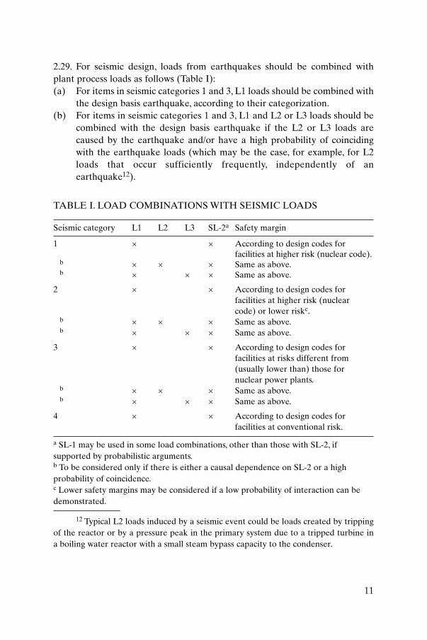
2.29. For seismic design, loads from earthquakes should be combined withplant process loads as follows (Table I):(a) For items in seismic categories 1 and 3, L1 loads should be combined with
the design basis earthquake, according to their categorization.(b) For items in seismic categories 1 and 3, L1 and L2 or L3 loads should be
combined with the design basis earthquake if the L2 or L3 loads arecaused by the earthquake and/or have a high probability of coincidingwith the earthquake loads (which may be the case, for example, for L2loads that occur sufficiently frequently, independently of anearthquake12).
11
TABLE I. LOAD COMBINATIONS WITH SEISMIC LOADS
Seismic category L1 L2 L3 SL-2a Safety margin
1 × × According to design codes for facilities at higher risk (nuclear code).
b × × × Same as above.b × × × Same as above.
2 × × According to design codes for facilities at higher risk (nuclear code) or lower riskc.
b × × × Same as above.b × × × Same as above.
3 × × According to design codes for facilities at risks different from (usually lower than) those for nuclear power plants.
b × × × Same as above.b × × × Same as above.
4 × × According to design codes forfacilities at conventional risk.
a SL-1 may be used in some load combinations, other than those with SL-2, ifsupported by probabilistic arguments.b To be considered only if there is either a causal dependence on SL-2 or a highprobability of coincidence.c Lower safety margins may be considered if a low probability of interaction can bedemonstrated.
12 Typical L2 loads induced by a seismic event could be loads created by trippingof the reactor or by a pressure peak in the primary system due to a tripped turbine ina boiling water reactor with a small steam bypass capacity to the condenser.
(c) For items in seismic category 2 which have been identified to interact withitems in seismic categories 1 and 3, the same combinations of seismiccategory 1 or 3 should be applied, possibly associated with different safetymargins.
(d) For items in seismic category 4, combinations according to nationalpractice should be applied to the relevant design basis loads.
2.30. For the seismic design of SSCs, external events such as floods or firesassumed to occur at the site as a consequence of an earthquake should be takeninto account. They should be defined on the basis of probabilisticconsiderations. These loadings as a consequence of an earthquake should becombined with either SL-1 or SL-2 loadings, with due account taken of eventtiming and duration.
SEISMIC CAPACITY
2.31. Acceptance criteria for load combinations, including the effects of SL-2with L1 or L2 loads, or L3 loads, should be the same as those adopted in relatedpractices for L3 loads acting without an earthquake.
2.32. Structures in seismic categories 1 and 3 may be designed to exhibit non-linear behaviour (by choice of material and/or geometry) provided that theiracceptance criteria (as expressed in terms of the value of a design parametersuch as elasticity, maximum crack opening, absence of buckling or maximumductility) are met with a safety margin consistent with the seismiccategorization. The incidence of irreversible structural behaviour (e.g. inrelation to limited ductility of joints) should be compatible with the expectedfrequency of occurrence of the associated seismic scenarios. In any case, thespecific acceptance criteria (e.g. leaktightness, maximum relative displacementand functionality) should be assessed explicitly, according to the seismiccategorization13.
12
13 In most States some acceptance criteria are lowered in the case of an extremeearthquake for some leaktight structures (e.g. containment and fuel pool). In this caseintegrity is only required in an extreme earthquake, but restoration of operation after-wards is conditional on a structural evaluation of the earthquake’s effects on theleaktightness of such structures.
2.33. Structures in seismic category 2 may also be designed to exhibit non-linear behaviour. Detailing of structural members, particularly joints andconnections, should be consistent with the ductility level required by theacceptance criteria.
2.34. Material properties should be selected according to characteristic valuessupported by appropriate quality assurance procedures. Appropriate ageingevaluation should be carried out to guarantee the long term safe performanceof materials and SSCs (Ref. [1], para. 5.47).
2.35. Specific evaluations should be carried out concerning the acceleration ofdegradation mechanisms by seismic events. If such mechanisms are responsiblefor any reduction in seismic capacity over the lifetime of the plant, additionalsafety margins should be adopted to guarantee the required safety level in thedesign after any seismic event.
2.36. To ensure adequate seismic safety, ductile design should be effected andgradual and detectable failure modes should be incorporated. The followingmeasures are a sample, indicative of what should be considered at the designstage:
— In reinforced concrete structures, brittle failure in shear and/or bond or inthe compressive zones of concrete should be prevented.
— An appropriate minimum compressive strength of the concrete should bedetermined to ensure that the ultimate strength of the structuralmembers is governed by the reinforcement.
— For reinforcement, an appropriate minimum ratio of the ultimate tensilestress to the yield tensile strength should be defined, to ensure a minimumductility.
— Structural joints, particularly in reinforced concrete structures, should bedesigned to provide a high ductility and a capability to accommodatelarge displacements and rotations; this provision should be consistentwith the acceptance criteria specified in the seismic categorization, but isintended also to take into account considerations relating to beyonddesign basis events.
— At least for the main coolant loops, it should be demonstrated that any‘reasonable’ defect that inspections may fail to detect will not propagateduring the plant lifetime and will also remain stable during anearthquake.
— Appropriate consideration should be given to ageing in order to providea basis for the assumption of ‘long term’ geometric configurations (e.g.
13
against creep and settlement) and ductile material properties (e.g. againstradiation embrittlement).
2.37. A particular case is represented by the application of the leak before breakconcept14: in cases where this criterion is applied, a specific evaluation of theseismic contribution to crack propagation should be carried out by analysis or bytesting, with procedures that are compatible with the required accuracy.
2.38. The acceptance criteria for seismic category 4 should at least followapplicable national standards and codes for conventional risk facilities.
CONSIDERATIONS FOR BEYOND DESIGN BASIS EVENTS
2.39. Seismic design should be carried out in accordance with the generalrecommendations outlined in the previous paragraphs and the designrecommendations given in Section 3 to provide margins for seismic events thatare beyond the design basis and to prevent potential small deviations in plantparameters from giving rise to severely abnormal plant behaviour (‘cliff edge’effects)15. In general it is not essential to quantify these margins.
2.40. For specific items for which general principles of seismic design cannot beobserved owing to highly non-linear behaviour (e.g. behaviour induced byunilateral restraints installed to meet other design criteria such as thermalloads), sensitivity studies should be performed and appropriate strengtheningmeasures should be taken to enhance safety margins.
14
14 The leak before break concept is a general approach in use in some States thataffects design, material selection, construction, quality assurance, monitoring andinspection. It has major effects on some design assumptions such as the transient load tobe considered for the design of fuel assemblies, the transient load for the design of thecoolant pressure boundary (the need for consideration of a double ended guillotinebreak is avoided) and the pipe whip load from a pipe break scenario. However, theapproach has been developed in many different versions in various States (including dif-ferent ranges of application: from the primary loop only to all safety related piping) andthere can be no general discussion in this Safety Guide.
15 A cliff edge effect is the effect of an abrupt transition from one status to another:a discontinuity in the first derivative of the response to a small deviation in a plantparameter.
CONTENT OF THE SAFETY ANALYSIS REPORT
2.41. The derivation of the design basis, general assumptions in design, the finalevaluation of the safety margin and the logic of the seismic monitoring should bedescribed in the safety analysis report (SAR). Technical reports should bereferenced and made available in order to ensure the traceability of the pro-cedures for analysis and testing followed for seismic qualification.Recommendations and guidance on the content of the SAR are given in Ref. [14].
3. SEISMIC DESIGN
SELECTION OF AN APPROPRIATE PLANT LAYOUT
3.1. In the early stages of the design of the plant, a preliminary layout of themain facilities should be prepared; this should be periodically reviewed toachieve the most suitable solution for the seismic design. All procedures forseismic design should be firmly based on a clear appreciation of theconsequences of past destructive earthquakes, and this knowledge should beadopted and realistically applied. In this preliminary work, the considerationsmentioned in this section should be taken into account to reduce the effects ofearthquakes on SSCs.
3.2. In the preliminary design stages, seismic effects (in terms of forces andundesired torsional or rocking effects) should be minimized by the appropriateselection of a structural layout applying certain general criteria, such as:
(a) Locating the centre of gravity of all structures as low as practicable;(b) Selecting a plan and elevation that are as simple and regular as
practicable, and also avoiding different embedment depths;(c) Avoiding protruding sections (i.e. lack of symmetry) as far as practicable;(d) Locating the centre of rigidity at the various elevations as close as
practicable to the centre of gravity;(e) Avoiding rigid connections between structures or equipment of different
categories and dynamic behaviour as far as practicable.
3.3. To reduce undesirable differential movements between structures,consideration should be given to locating the structures, to the extentpracticable, on a common foundation structure, or at least avoiding different
15
embedment depths. In siting the plant, having significant differences in soilproperties below the foundation structure should be avoided. All individualfootings or pile foundations should be tied within the structural floor plan.
3.4. Regular layouts and simple connections between structures should beadopted to facilitate the seismic analysis and to improve the seismic behaviourof piping and equipment appended to buildings. In crossing structuralboundaries (e.g. with expansion or construction joints), in making connectionsbetween buildings or in bringing services to and from a building throughunderground conduits, care should be taken to avoid damage or failure due todifferential movements.
3.5. A specific approach could also be applied to the whole design or to partsof it through the use of antiseismic systems and devices such as base isolators.This technique should be integrated with special provisions in the design of amore complicated foundation system and special operational procedures forthe periodic inspection and maintenance of the isolation devices; theseadditional efforts can be largely compensated for by a significant reduction inseismic demand on SSCs. The increased relative displacement field may giverise to concerns for the design of structural interfaces and connections, and itshould be explicitly addressed in the design. Moreover, the effects of usingseismic isolators should be evaluated in relation to the response to other loadswhere the response may be worsened.
GEOTECHNICAL PARAMETERS
3.6. Information on site specific soil properties should be available from siteinvestigation campaigns, laboratory analyses and engineering syntheses, asdescribed in Ref. [3], in which guidance is also given on the extension of thecampaigns and their requirements. Their accuracy should be compatible withthe overall reliability required in the design process. Procedures for soilmodelling are discussed in Section 5.
CIVIL ENGINEERING STRUCTURES
3.7. Particular attention should be paid to the following issues in the designand design review of structures:
16

(a) The adequacy of the supporting soil [3].(b) The suitability of types of foundation supports or of different types of
foundations under interconnected structures (e.g. it should be avoidedthat part of the foundations of one building is supported on piles or rockand part is set directly onto soil).
(c) A balanced and symmetrical arrangement of structural frames and shearwalls to achieve optimum stiffness and distribution of loads and weightwith minimum torsional effects.
(d) The need to prevent collisions between adjacent buildings (pounding) asa consequence of their dynamic deformations (this phenomenon may alsooccur in weakly coupled structures).
(e) The adequacy of the connections of annexes and appendages to the mainstructure (see also item (d)).
(f) The need to ensure sufficient resistance of essential structural elements,especially resistance to lateral shear forces.
(g) The need to ensure sufficient ductility and to avoid brittle failure byshear or compression; for example, by ensuring that there is anadequate amount of reinforcement steel, and in particular that thereare enough hoop ties for columns (i.e., adequate confinement) toprevent the premature buckling of compression bars located in plasticregions.
(h) The arrangement and distribution of steel reinforcement: too high aconcentration of rebars may cause cracking of concrete along the lines ofthe rebars.
(i) The need for joints between structural elements and anchorages of itemscast into concrete to be designed so as to ensure ductile failure modes(e.g. anchor lengths should be sufficiently long to avoid pull-out andadequate reinforcement with transverse ties should be provided) and, tothe extent practicable, for connections between members to be made asstrong and as ductile as the members that they connect.
(j) An evaluation of the non-linear bending moments induced by the verticalforces and the horizontal translation in the event of an earthquake (theso-called ‘P–D’ effect).
(k) The additional effect of groundwater buoyancy on the foundation.(l) The possibility of lateral sliding of structures on waterproofing material
(especially if wet) in an earthquake.(m) The dynamic effect of ‘non-structural’ elements, such as partition walls, on
structural elements.(n) The detailed design of construction joints and thermally induced stresses
in large integrated monolithic structures designed to resist differentialearthquake motions.
17
(o) The effects of the transfer of forces in cases where the stiffness of acontainment vessel is greater than that of the surrounding concretestructures, and where they are interconnected or may interact so that theearthquake loads on the concrete structures may be transferred to thecontainment vessel. Owing to the complexity of the interactions of suchstructures, it is difficult to evaluate such forces, and such structures shouldbe decoupled above the foundation level to the extent possible.
(p) The adequacy of the anchorages of mechanical components to civilstructures.
(q) The need to strengthen non-structural walls or steelworks to preventthem or parts of them from falling on safety related items.
EARTH STRUCTURES
3.8. The following safety related earth structures may be encountered atnuclear power plant sites:
— Ultimate heat sinks: dams, dykes and embankments;— Site protection: dams, dykes, breakwaters, sea walls, revetments;— Site contour: retaining walls, natural slopes, cuts and fills.
3.9. These earth structures should be designed in accordance with theirseismic categorization with adequate seismic capacity and for the followingseismic related effects:
(1) Slope failure induced by design basis vibratory ground motions, includingliquefaction;
(2) Sliding of structures on weak foundation materials or materials whosestrength may be reduced by liquefaction;
(3) Failure of buried piping or seepage through cracks induced by groundmotions;
(4) Overtopping of the structure due to tsunamis on coastal sites or seiches inreservoirs, earth slides or rock falls into reservoirs, or failure of spillwayor outlet works;
(5) Overturning of retaining walls.
3.10. The relevant design procedures are considered in Ref. [3].
18
PIPING AND EQUIPMENT
3.11. Specific provisions should be made with regard to the seismic design ofequipment and piping supports:
(a) Care should be taken in the design of the supports to ensure that all jointsare designed to behave as assumed in the analysis for the support and totransmit the full range of loads determined in the members connected tothem. In particular, if restraints on six degrees of freedom are used, theyshould be designed, manufactured and installed so as to minimize thepotential for any unexpected failure or crack initiated in the supportingelement to propagate to the functional parts, such as the pressurized shellor the primary piping.
(b) Care should be taken in the design of devices for anchoring equipment,for example, in the possible use of hook shaped or end plate anchor bolts,to ensure that all potential forces and moments are fully evaluated andthat anchoring materials are suitable for their purpose. It should beensured that baseplates are sufficiently stiff to avoid prising effects andthat anchor bolts are adequately tightened to avoid rocking effects,lowered frequencies, increased response levels, loads higher than thedesign loads and increased risk of loosening, pull-out or fatigue.Oversized or redundant anchors, pre-loaded to close to their yield pointon installation, should be used.
3.12. The following points should be taken into account to improve theresistance to earthquake induced vibration:
(1) Equipment support legs should be braced unless their dimensionswarrant departure from this recommended practice. Resonance should beavoided and, in some cases (e.g. for core internals for which it is difficultto avoid resonance by means of modifying the design), the vibrationcharacteristics of the reactor building’s internal structure itself may bemodified to prevent resonance effects. If systems are made stiffer, theeffects of thermal stresses, other dynamic loads and differential motionsof the supporting points should be considered.
(2) Resonance of equipment such as piping, instrumentation and coreinternals at the frequency of the dominant modes of supporting structuresshould be avoided as far as is practicable. In some cases, where theresponse of equipment, although significant, cannot in practice bereduced by other means, the damping of the system may be increased bymeans of suitable design modifications.
19

(3) To provide seismic restraints for piping and components and at the sametime allow freedom for thermal deformations, dampers or motion limitingstops may be used. Excessive use of snubbers should be avoided owing tothe implications of these in relation to operation and maintenance.Realistic damping values to define seismic design inputs should be used,since overdesign for seismic loads can reduce the design margins forthermal loads (through the restraint of free displacement).
(4) Particular attention should be paid to the possibility of collision betweenadjacent components, or between components and adjacent parts of abuilding, as a consequence of their dynamic displacement. Allowanceshould also be made for the flexibility of connections between suchcomponents, between components and building penetrations, andbetween components and underground connections to buildings, as wellas between buildings.
(5) Piping support should be arranged so that loads transferred to theequipment are at a minimum.
3.13. Such measures should also be taken with reference to all possible sourcesof vibration (e.g. aircraft crash, operational vibrations and explosions), as theireffect may be different from the effects induced by seismic vibrations.
SELECTION OF APPROPRIATE DESIGN STANDARDS
3.14. According to the experience in different States, very often differentstandards for design, material selection and construction quality are applied inthe same project for the different disciplines (mechanical, civil and electrical).An early assessment of the consistency of the respective safety margins andrelevant uncertainty levels and of their agreement with the general safetyrequirements for the project should be carried out in the different design tasks.
3.15. Such an assessment may in fact affect the management of the project andthe entire quality system required for the design assessment and theconstruction phase, by ensuring that the design assumptions in terms of globalplant safety are realized in the design.
3.16. In particular, in the selection of appropriate design standards, thecompatibility and suitability of the following options should be evaluated:
— National and international seismic design standards, both ‘nuclear’ (forinstallations potentially posing a higher risk for workers, the public and
20
the environment) and ‘non-nuclear’ (for facilities presenting aconventional risk);
— National and international nuclear design standards that do not includeseismic design standards;
— National non-nuclear and non-seismic design standards.
Safety margins, design procedures and requirements for quality assurancethroughout the entire design process, from the site data to the calculation ofmaterial capacity, should be compared in the evaluation. Mixing designstandards is not good practice and should be avoided owing to the consequentintrinsic difficulty of evaluating the global safety margin of the design.
3.17. The overall safety margins provided by the design should then beevaluated in the safety assessment phase, in accordance with the proceduresrecommended in Ref. [9].
PERIODIC SAFETY REVIEW
3.18. As required in Safety of Nuclear Power Plants: Operation [15], and inaccordance with the recommendations of Ref. [16], periodic safety reviews ofthe plant should be carried out at regular intervals or whenever evidence isgained of a significant modification of any design assumption. Operatingexperience shows that seismic re-evaluation as a consequence of seismic hazardupgrading has been one of the major issues in periodic safety reviews in recentyears. Adequate long term configuration control and monitoring (Section 7)should be put in place to support periodic safety reviews of this kindadequately.
3.19. In such a review the original design assumptions should be assessedagainst new site evaluations (e.g. reflecting the occurrence of new events or theavailability of new evidence of the local tectonics), modern standards for designand qualification, and newly available methods of design. The result willinfluence considerations in the renewal of the operating licence in accordancewith the procedures discussed in Ref. [16].
3.20. Upon the completion of a periodic safety review, the ongoing validity ofthe seismic qualification of equipment should be ensured.The need to maintainthe seismic qualification status of equipment should be reflected in theprocedures for controlling changes to the plant, including changes to itsoperating procedures. In this framework, beyond the normal good
21

housekeeping standards expected for a nuclear installation, areas adjacent toseismically qualified SSCs should be maintained free from interaction hazards.
4. GENERALITIES ON SEISMIC QUALIFICATION
4.1. Seismic qualification of items important to safety16 can be performed bythe use of one or more of the following approaches:
— Analysis;— Testing;— Earthquake experience;— Comparison with already qualified items (similarity).
It is also possible to use combinations of these methods, as shown in Fig. 1.
4.2. Seismic qualification generally includes qualification of structuralintegrity as well as qualification for operability or functionality. Seismicqualification is made directly on actual or prototype items; or indirectly on areduced scale model, a reduced scale prototype or a simplified item; or bymeans of similarity where this can be established between a candidate item anda reference item and direct qualification has been performed on the latter.Whatever the method selected, it should accurately represent the actualperformance of the component or structure when it is subjected to theprescribed effects.
4.3. Care should be taken to ensure that consistent levels of sophistication inmodelling apply for all the items to be qualified.
4.4. Any qualification programme requires that the boundary conditionsapplying for this item in the plant during an earthquake are correctly orconservatively simulated, or that any departure from them will not significantlyinfluence the result.Among these conditions, the most important are: excitationconditions, support conditions, environmental conditions and operationalconditions.
22
16 Investigation or modelling of soils, together with structures and foundationmedia, is largely outside the scope of this Safety Guide. This subject is treatedcomprehensively in Ref. [4].
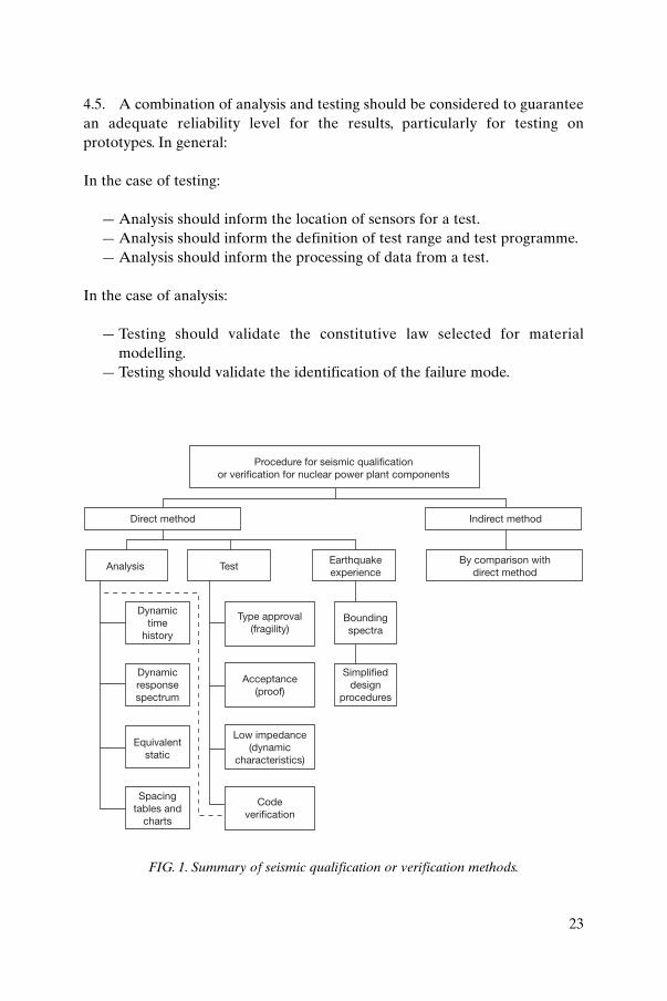
4.5. A combination of analysis and testing should be considered to guaranteean adequate reliability level for the results, particularly for testing onprototypes. In general:
In the case of testing:
— Analysis should inform the location of sensors for a test.— Analysis should inform the definition of test range and test programme.— Analysis should inform the processing of data from a test.
In the case of analysis:
— Testing should validate the constitutive law selected for materialmodelling.
— Testing should validate the identification of the failure mode.
23
Procedure for seismic qualificationor verification for nuclear power plant components
Direct method Indirect method
Analysis TestEarthquakeexperience
Dynamictime
history
Dynamicresponsespectrum
Equivalentstatic
Spacingtables and
charts
Type approval(fragility)
Acceptance(proof)
Low impedance(dynamic
characteristics)
Codeverification
Simplifieddesign
procedures
Boundingspectra
By comparison withdirect method
FIG. 1. Summary of seismic qualification or verification methods.
4.6. Seismic qualification by analysis should be used for items without afunctional safety requirement that are unique and that are of a size or scale topreclude their qualification by testing. Civil engineering structures, tanks,distribution systems and large items of equipment are usually qualified byanalytical methods after the modelling requirements discussed above havebeen fulfilled.
4.7. The continuing increase in analytical capabilities has allowed the use ofhighly sophisticated non-linear constitutive laws to model materials inconjunction with very finely detailed numerical models. This has enabledvalidating results to be derived from alternative software, thus enhancingconfidence in the appropriateness and correctness of the results. However, asall analytical techniques have limits of applicability, an appropriate validationphase of methods and software verification should be carried out by means ofeither an independent analysis or a test.
4.8. For equipment, a systematic evaluation of the possible modes of failurerelated to earthquakes should be carried out with reference to the acceptancecriteria assigned by the safety classification. This should be carried out bymeans of specific tests. However, as sophisticated techniques of analysis bycomputer simulation are improving, even the performance of ‘active’equipment (e.g. pumps, valves and diesel generator sets) under earthquakeconditions may be predicted with some confidence by means of analysis. Theoperability of active components may be qualified by analysis only when theirpotential failure modes can be identified and described in terms of stress,deformation (including clearances) or loads. Otherwise, testing or earthquakeexperience should be used for the qualification of active components.
4.9. In general, it should be understood that a high level of analyticalsophistication still requires a number of assumptions to be made and producesat best only an indication of seismic behaviour. Data from testing or experienceshould always be used to validate analytical results, particularly with regard tofunctionality.
4.10. In addition to the methods described above, seismic qualification of itemsin seismic category 2 should be carried out by means of dedicated expertwalkdown, in which all potential interaction mechanisms should be evaluated:mechanical interaction or interaction by the release of hazardous substances, fireand flood (earthquake induced), and the prevention of safety related operatoraction through the impairment of access. In this sense, such walkdown methodscould be considered part of the design assessment; see Ref. [9] for their planning.
24
Seismic qualification by means of analysis is treated in Section 5.The other three means form the subject matter for Section 6.
5. QUALIFICATION BY ANALYSIS
MODELLING TECHNIQUES
Modelling of seismic input
5.1. The dynamic input motions used to qualify items are conservatively butrealistically defined by either time histories or response spectra. In the case ofresponse spectra, the spectrum shape, the peak ground acceleration and theduration of the motion should be derived consistently with the hazarddefinition, as discussed in Ref. [2].17
5.2. It is common practice to apply the horizontal and vertical components ofthe seismic input simultaneously to the numerical model. In this case thecomponents should be statistically independent. When the input componentsare applied individually, the corresponding structural responses should besuitably combined to account for the statistical independence of the twocomponents of the input.
General modelling techniques for structures and equipment
5.3. Nuclear power plants can be modelled in many different ways accordingto their structural characteristics (e.g. lumped mass models, one dimensionalmodels, axisymmetric models, two or three dimensional finite element models).The most suitable and reliable numerical technique should be used in order tominimize the contribution of the modelling techniques used to theuncertainties in the results. The continuing increase in the speed ofcomputation and the progress in the graphical display of results have enabledthe use of greatly refined structural and material models.
25
17 In some States, a constant acceleration input is used for a preliminary design ora simplified design, especially for items of lesser importance, and this is also used for thevertical direction.
5.4. Typical models for the structures and equipment of nuclear power plantsare shown in Figs 2 and 3. These figures are included to demonstrate the widerange of complexity possible in the way analytical models may be constructed.While simple conceptual models are capable of capturing the global pattern of
26
M KIH
KQ
M3
M2
M1
K
K3
K2
K1
M3
M2
M1
K3
K2
K1KH
KQ
M3
M2
M1 KH
KV1 KV2
(a) (b) (c) (d)
K3
K2
K1
Lumped massor rigidbody model
Lumpedmass model
Beam or onedimensional finiteelement model
Beam or one dimensional finiteelement on soil springs model
K: 6 × 6 Stiffness matrixKQ: Rotational spring stiffnessM: Lumped masses
KH: Horizontal spring stiffnessKV: Vertical spring stiffness
(e) (f) (g)
Two dimensionalfinite element modelrepresenting building andsoil–structure interaction.
Two dimensional finiteelement or axisymmetricbuilding and soil–structureinteraction. Elements in thecontainment volume maymodel internal explosionsand non-uniformtemperature effects.
Three dimensionalfinite element modelof building andsoil–structure interaction(Note that finite element meshesneed not necessarily match atthe foundation level: differentgrid densities may beneeded.)
FIG. 2. Examples of various models associated with dynamic or static analysis.
response in complex structural or mechanical systems, local patterns of stressesor deformations are best obtained from detailed models.
5.5. The use of simple lumped mass models for structural components or rigidmass models with spring supports to represent foundation–structureinteractions should be restricted to the purpose of checking the accuracy ofcalculations made with more detailed models.
5.6. There are sufficient grounds to attribute confidence to the outcome ofmodels that have many thousands of degrees of freedom and that exploitsophisticated soil modelling techniques if these analytical tools have beenbenchmarked against experimental or theoretical results on the basis of methodsgenerally accepted by experts. The validation of codes used (i.e. the intrinsic
27
(a) (b) (c)
Lumped mass model Lumped mass model withflexible foundation
Beam or one dimensionalfinite element model
(d) (e) (f)
Two dimensional finiteelement or axisymmetricequipment model (for tanks)
Combined two and onedimensional finiteelement model
Model of a threedimensional thickwalled concretepressure vessel
FIG. 3. Examples of various equipment models associated with dynamic or static analysis.
accuracy of the code) and the verification (i.e. the use of the code in a specificapplication) should be addressed in the safety related documentation [12].
5.7. The mass characteristics of the structural systems should be adequatelyincorporated into the analytical models. Modelled mass should includesuitable contributions from operational loads (including the live loads),selected in accordance with probabilistic evaluations for its combination withearthquakes and in accordance with design considerations for its un-favourable effects.
5.8. More than one model should be developed if there is uncertainty aboutthe response of some parts of the structure. A sensitivity analysis should bemade to provide the basis for this decision and this should also help in thechoice of the size, type and number of finite elements if this modellingtechnique is used. Models should be validated by means of testing or bycomparison with numerical models with different formulations in order toresolve possible uncertainties.
5.9. The selection of an adequate number of degrees of freedom is oftenstraightforward, for example in the calculations for a conventional buildingwith floors. In other cases, for example for shell or beam type structures, theselection is not obvious and will depend on the number of modes needed forthe seismic analysis. The detail of the model should be consistent with theobjectives of the required qualification and should be able to represent thecorresponding local modes. A practical way to ensure that a sufficient numberof modes (missing mass) are included in the analysis is to add a rigid body or azero period acceleration mode, which corrects for the highest frequency modesthat may otherwise not be included in the evaluation. An evaluation of themissing mass should be carried out as a final confirmation of the cut-off. Itshould also be ensured that correct reactions at supports are computed, withinthe limits of the finite element model.
Decoupling criteria
5.10. Nuclear power plant structures may be very complex and a singlecomplete model of the entire structure would be too cumbersome or possiblyill conditioned. The analysis should therefore identify the substructures bydefining main systems and subsystems.
5.11. Major structures that are considered in conjunction with foundationmedia to form a soil–structure interaction model should constitute the main
28
systems. Other SSCs attached to the main systems should constitute thesubsystems.
5.12. Certain criteria should be used to decide whether a particular subsystemshould be taken into account in the analysis of the main system. Suchdecoupling criteria should define limits on the relative mass ratio and on thefrequency ratio between the subsystem and the supporting main system; specialcare should be taken to determine whether there is a possibility of resonancebetween the subsystem and the main system.
5.13. If the decoupling criteria are not satisfied, a suitable model of the subsystemshould be included in the model of the main system. For a subsystem having allits resonant frequencies (with the flexibility of the support taken into account)higher than the amplified frequencies (above 15 Hz for the usual design basisearthquakes), only the mass should be included in the model of the main system.
5.14. For detailed analysis of subsystems, the seismic input, including themotion of differential supports or attachments, should be obtained fromthe analysis of the main model. When coupling is significant, the model of thesubsystem should be included in the analysis of the main system.The subsystemmodel should have at least the same natural frequencies and modal masses asthe detailed model of the subsystem in the frequency range of interest.
Material properties
5.15. Modelling of reinforced concrete structures is usually undertaken byassuming that sections are uncracked. However, the effects of reduced sectionproperties, equivalent to some degree of cracking, should also be evaluated ina sensitivity analysis.
5.16. The selection of soil properties, frequencies and strain dependencesshould be adequately documented. Methods of investigation and testingprocedures are discussed in Ref. [3]. In this design context, a range ofvariation in soil properties should be defined to take account of uncertaintiesin geotechnical parameters, as suggested in Ref. [3]. The effect of suchvariation may envelop the variation in structural properties (e.g. due to acracked section): this aspect should be explicitly addressed in the safetyevaluation.
5.17. The structural damping used in the qualification analysis should beconservatively but realistically defined. To this extent, experimentally
29
determined damping for a material or a structural system should be evaluatedwith care since it might not be representative of the actual structural behaviourof the component installed in the plant.
5.18. Damping values used in seismic analysis should be mean or mediancentred.
5.19. The value of (geometrical and material related) damping for soil that is tobe used in the seismic analysis should be obtained by conservatively appliedengineering judgement. Variation of damping factors with the frequency andamplitude of motion may be taken into account if this is warranted on the basisof the experimental data.
5.20. Particular care should be taken with the numerical modelling for the partsof the model with different damping values (e.g. soil, structure andcomponents).
Interactions with soil, fluid and other structures
5.21. In the modelling of buildings or large ground founded tanks, thesoil–structure interaction should be taken into account and explicitly modelled.With consideration of embedment, depth to water table, and locally modifiedproperties of soil, input ground motions defined for surface conditions shouldbe deconvolved to prescribed levels of the soil–structure complex, typically atthe foundation level [3]. This process should include the rotational input. In theevent that high reduction of input ground motion is obtained, it should becarefully justified.
5.22. Effects of soil–structure interaction should be evaluated by appropriatemodelling of the soil–structure complex. With growing confidence in analyticalprocedures utilizing robust material laws, this task can be accomplishedrelatively easily even for very detailed models. However, simplified methodsmay be applied if it is demonstrated that they are conservative.The appropriaterange of values applied for soil properties, and the way they are modelled,should be thoroughly documented. Special attention should be given to themodelling of the soil boundaries, which should account for radiative effects ofseismic waves in unbounded media.
5.23. Lateral earth pressure induced on underground portions of structures orfoundations by ground motion should be evaluated in accordance with Ref. [3].
30
5.24. The liquefaction potential of saturated granular soil layers, the potentialfor a loss of bearing capacity and the potential for settlement should beevaluated for the reference design earthquake, usually defined as the SL-2ground motion, and the existence of appropriate safety margins should bedemonstrated, as explained in Ref. [3].
5.25. The following effects of an earthquake on buried independentstructures (e.g. buried pipes, ducts and well casings) should be taken intoaccount:
— Deformations imposed by the surrounding soil during and after theearthquake;
— Differential displacements or loads at end connections to buildings orother structures;
— Effects of contained fluids (impulsive loads, hydrostatic pressure andsloshing effects).
Recommendations for a seismic design of buried structures are provided inRef. [3].
5.26. Adjacent buildings or components on the same foundation structureshould be included in the same model when the relative displacement canaffect a specified acceptance criterion (such as the value of a design parameterindicating elasticity, maximum crack opening, absence of buckling or maximumductility).
5.27. The adequacy of the gap dimension in structural joints between adjacentstructural parts or between adjacent buildings should be checked to avoidpounding and hammering, with account taken of the need for an adequatesafety margin.
5.28. Subsystems that may exhibit inertial effects from the liquid contained intanks and pools should be taken into account in the modelling of the structures.In particular, the vertical motion due to the breathing mode of vertical flexibletanks should be evaluated and carefully considered.
5.29. Moreover, sloshing liquid can generate significant impulsive loads andimpact loads up and down as well as cyclic loads on structures or parts of them.In particular, such impulsive loads can cause the failure of tank roofs and ofattachments to the walls of tanks and pools in their path. Impulsive loads, whendetected, should be modelled with dedicated procedures.
31
5.30. Where appropriate, simplified models built up of combinations ofequivalent masses and springs should be considered to ensure that the sloshingresponse can be correctly captured for the required frequency range.
5.31. The damping coefficient for the sloshing mode should be very low18, sincethe damping associated with the impulse mode of vibration is typicallyassociated with the container material, the connections and the anchorageused. However, if the vertical component of the acceleration at the free watersurface is expected to be greater than 1.0g, additional waves at the free surfacecould be generated. In such cases, non-linear damping effects should beconsidered in the response.
General modelling techniques for mechanical and electrical components
5.32. Mechanical and electrical components other than primary loop items areusually represented in the analysis by a single mass or a multimass systemattached to the supporting building. Their dynamic coupling to the mainbuilding can usually be neglected, provided that they meet the generaldecoupling criteria discussed above.
5.33. The modelling of equipment is typically divided into several categories, asshown in Fig. 3. For components not modelled together with the supportingstructure, the input for analysis is the floor response, expressed in terms ofeither design floor time histories19 or design response spectra20.
5.34. The quantity of insulation, the size, location and number of support gaps,the connection type (e.g. flanged), the frequency of response, and the use ofyielding or energy absorbing support devices may all have an effect on thedamping which is to be considered in the design of the components. This effectshould be carefully checked and adequately modelled.
32
18 The damping coefficient for the sloshing mode should typically be taken as0.5% or less.
19 The design floor time history is a record of the floor motion with time for thestructure under consideration derived from the design basis ground motion, withaccount taken of the variability of and uncertainty in the input ground motion and thecharacteristics of the building and the foundation.
20 In some States, an equivalent static input is used for the vertical direction.
5.35. For vessels and tanks that contain liquids, the effects of sloshing andimpulsive loads, including frequency effects, should be considered. The effectsof liquid motion or pressure changes on submerged structures should also beconsidered. These effects may involve hydrodynamic loads from the fluid and areduction of functional capability (e.g. loss of shielding efficiency of fuel poolsor disturbance of instrument signals).
General modelling techniques for distribution systems
5.36. The response of distribution systems (piping, cable trays and cableconduits) to earthquake excitations tends to be quite non-linear. Computationsof stresses and support reactions by means of linear elastic analyses provideapproximate indications of stresses and support loads that are suitable forcomparison with acceptance criteria to determine the adequacy of the design,but such computations should not be applied for deriving accurate values ofactual stresses and support reactions. Nominally fixed supports for distributionsystems with some limits on deflections may be considered rigid for modellingpurposes.
5.37. The flexibility or stiffness of elements of piping systems such as elbows,tees and nozzles should be considered in the model. Spring hangers may beignored in the seismic analysis of piping. If there is a pump or a valve in thepiping system, its contribution to the response should be evaluated. Alladditional masses, including their eccentricities, such as valve actuators, pumps,liquid inside pipes and thermal insulation, should be taken into account.
5.38. When distribution systems are connected to two or more points havingdifferent movements and applicable response spectra, a single responsespectrum of a particular support point should be applied with care. To accountfor inertial effects, either an envelope spectrum or multiple spectra should beapplied. However, the results are not always conservative and engineeringjudgement should be used in their evaluation. In the event that results areunreliable, methods should be used in which multisupport excitation isconsidered in conjunction with modal analysis.
5.39. In addition to inertial effects, careful consideration should be given to theeffects of differential motions between supports, since experience ofearthquakes has demonstrated that this phenomenon can be a majorcontributor to the seismically induced failure of piping systems.
33
ANALYTICAL TECHNIQUES
Analytical methods for structures
5.40. When the output of the numerical analysis is requested in terms of floorresponse spectra21, maximum relative displacements, relative velocities,absolute accelerations and maximum stresses during an earthquake, lineardynamic analysis (e.g. direct time integration, modal analysis, frequencyintegration and response spectrum) is generally adequate for most models.Alternatively, non-linear dynamic analysis should be used where appropriateor necessary (e.g. structural lift-off, non-linear load dependent support,properties of foundation materials in soil–structure interaction problems orinteractions between solid parts).
5.41. The trade-off between linear and non-linear solutions is governed by theconditions in each individual case: the latter usually require better definedinput parameters, where these introduce uncertainties. The decision shouldtherefore be informed by conducting parametric studies.
5.42. Simplified methods, such as the equivalent static, should be restricted touse for assessment purposes.
5.43. In the response spectrum method, the maximum response of each modeshould be calculated by direct use of the design response spectrum. Themaximum response in each principal direction should be determined by anappropriate combination of the modal maxima, such as the square root of thesum of the squares of each modal response, or by the complete quadraticcombination procedure. For closely spaced modal frequencies, a conservativeprocedure should be applied by taking the sum of the absolute values of eachclosely spaced modal and rigid response. The missing mass as a function of themodelling detail, cut-off frequencies and modal participation factors used inthe analysis should also be carefully assessed and documented.
5.44. Responses due to input acceleration in the three different directionsshould be combined by taking the square root of the sum of the squares ofindividual responses. In some States, horizontal input motion is defined as theresultant in one of the two reference horizontal orthogonal directions and iscombined with the vertical motion to determine the worst case response.
34
21 The floor response spectrum is the response spectrum for floor motion at a par-ticular elevation of a building for a given input ground motion.
5.45. In the time history22 method, the structural response of the system shouldbe calculated as a function of time either directly or after a transformation tomodal co-ordinates (for linear models only). The input motion should berepresented by a set of natural or artificial time histories of acceleration atground level or a specific floor level, suitably chosen to represent the designresponse spectrum and the other characteristics of seismic hazard (e.g. duration).
5.46. An appropriate time integration step should be chosen, consistent withthe level of detail required in the results and with the general modellingassumptions (e.g. grid density).
5.47. For non-linear analysis, the linear combination of the results fromdifferent load combinations is no longer valid. In such cases, conservativeenveloping procedures should be used, after suitable validation.
5.48. For items in seismic categories 1 and 3, methods relying on ductilityfactors applied either to internal forces, evaluated linearly, or to the inputspectra should be used for checking purposes only. For items in seismiccategories 2 and 4, simplified procedures using ductility factors can be followedwhere appropriate, but an adequate justification of their values should beprovided, carried out either by testing or by analysis.
Evaluation of floor response spectra
5.49. The floor response spectra, typically used as the seismic input forequipment, should be obtained on the basis of the structural response to thedesign basis ground motion. Natural or artificial time history motions that canbe shown to generate response spectra at least as conservative as the responsespectra for the design basis ground motion should be used as input to thestructural analysis.
5.50. Alternatively, direct methods may be used to calculate design floorresponse spectra23, on the basis of simplified engineering assumptions about
35
22 The time history is a record of earthquake motion over time or an earthquakeresponse motion with time for a particular floor or at a particular level for a structureresting on the ground.
23 The design floor response spectrum is the response spectrum for floor motionat a particular elevation of a building and is obtained by modifying one or more floorresponse spectra to take into account the variability of and uncertainty in the inputground motion and the characteristics of the building and the foundation.
the relation between the free field ground motion and the floor responsespectra. However, the conservatism of the resulting floor response spectrashould be compared with that provided by the time history solution.
5.51. A critical review of the calculated floor response spectra should be made,on the basis of sound engineering judgement, in which their shape and therelation between the vibration characteristics of the building and thesupporting foundation materials should be considered.
5.52. The calculated floor response spectra should be broadened to account forpossible uncertainties in the evaluation of the vibration characteristics of thebuilding’s components24. The extent of broadening may be reduced ifparametric studies are performed to account for uncertainties relating to thesoil modelling. Alternatively, segments of broadened spectrum spectra can beused sequentially to analyse the components. For systems having closely spacedfrequencies, the use of such segmented response spectra can help to avoidundue conservatism.
5.53. Consideration should be given to the modification of input for the floorresponse spectra for equipment attached to very flexible structural members(for vertical amplification due to floor flexibility), or when significant torsionalmotion of the building occurs. When the centre of stiffness and centre of massof the building are significantly different, and when this has not beenconsidered in the modelling of the building structure, either items located awayfrom the centre of stiffness should be analysed according to non-linearprocedures or the floor response spectra should be modified to take account ofthe torsional response of the support structure.
5.54. Concurrently, appropriate modifications should be made to the floorresponse spectra if significant incursion into the range of non-linear structuralresponse occurs. The value of ductility associated with any item should beconsistent with its structural detailing.
Analytical methods for equipment
5.55. The calculated stresses and reaction loads in the equipment andequipment supports should be a direct output of either dynamic or staticanalysis. It should be noted that electrical equipment, exclusive of anchorage or
36
24 Typical values in use in States are ±10 to ±15%.
support, is generally only evaluated for operability by means of testing or byusing experience data. For this reason, analysis of these components shouldassume an elastic response of the electrical cabinet, panel or rack structure, intheir loaded configuration, to calculate in-cabinet transfer functions and toevaluate support loads or anchorage loads.
Analytical methods for distribution systems
5.56. For distribution systems (e.g. piping, cable trays, conduits, tubing andducts and their supports), modal response spectrum analysis may be used forthe seismic design of large bore (diameter greater than 60 mm) piping of safetyclassified systems, while the static method is usually applied for the analysis ofsmall bore piping. Spacing tables and charts based on generic analysis or testingare also used in the evaluation of small bore piping and are typically used toevaluate cable trays, conduits, tubing and ducts. Simplified analytical or designprocedures based on data drawn from experience of earthquakes may also beused. All such simplified techniques should be fully validated to show theirdegree of conservatism in comparison with more refined modelling techniquesand they should be suitably documented.
5.57. A variation of the static method for small bore piping of 60 mm or less indiameter is used in some States. The maximum acceleration of the design basisresponse spectrum in the frequency range between 0.5ff and 2.0ff (where ff is thefundamental frequency of the equipment) is taken as the design acceleration. Asuitable amplification factor, typically chosen as 1.0–1.5 depending on thenumber of supports, is then applied. Such an approach should be validated withrigorous analytical or experimental methods before application.
6. SEISMIC QUALIFICATION BY MEANS OF TESTING,EARTHQUAKE EXPERIENCE AND INDIRECT METHODS
SEISMIC QUALIFICATION BY MEANS OF TESTING
Type of testing and typical application fields
6.1. A method of direct seismic qualification of items is the testing of theactual item or prototype. If the integrity or functional capability of an item
37
cannot be demonstrated with a reasonable degree of confidence by means ofanalysis, a test should be carried out to prove its capability or to assist directlyor indirectly in qualifying the item.
6.2. Types of testing include:
— Type approval test (fragility test);— Acceptance test (proof test);— Low impedance test (dynamic characteristic test);— Code verification test.
6.3. Test qualification of items in seismic categories 1 and 3 should be carriedout when failure modes cannot be identified or defined by means of analysis orearthquake experience. Direct qualification by testing makes use of typeapproval and acceptance tests. Low impedance (dynamic characteristic) testsshould be limited to identify similarity or to verify analytical models. Codeverification tests should be used for the generic verification of analyticalprocedures, which typically use computer codes. The methods of testing dependon the required input, weight, size, configuration and operational characteristicsof the item, plus the characteristics of the available test facility.
6.4. The type approval (fragility) test should be used for standard electricalcomponents and mechanical components when design margins to failure,damage or non-linear response and identification of the lower bound failuremode have to be evaluated. Such testing is typically carried out by means of ashaking table. The fragility test should be able to detect unexpected failuremodes or potential malfunctions, because the test conditions typically cover awider spectrum of loading than that required for the design basis, providinginformation also on the behaviour in beyond design basis conditions.
6.5. The acceptance (proof) test is also used for electrical and mechanicalcomponents to demonstrate their seismic adequacy. It is typically performedby manufacturers to demonstrate compliance with procurementspecifications and should not be used in the evaluation of seismic margins orthe analysis of failure modes. Such testing is typically carried out by means ofa shaking table.
6.6. The code verification test is important for reliable analytical work.Computer codes should be verified before their application by means ofanalyses made using an adequate number of test results or results obtainedfrom other appropriate computer codes or analytical procedures. A number of
38
test results that cover the range of interest should be correlated with theanalytical results [12, 17].
Testing devices
6.7. Type approval and acceptance tests are usually carried out in a laboratory.One or more of the following facilities should be available:
— A shaking table (one or more degrees of freedom);— A hydraulic actuator (large and stiff reaction walls are usually required);— An electric actuator;— A mechanical actuator (unbalanced mass type);— An impact hammer;— A blast actuator.
6.8. In case low impedance (dynamic characteristic) tests are carried out onitems in situ, items are typically tested by means of mechanical actuation,impact, blast and other low energy exciters as well as ambient excitation. Thesetests should not be used for direct seismic qualification of the item but can beused to define dynamic characteristics, including support, which can then beused in analysis or in other tests to qualify the item of interest.
Test planning
6.9. Conducting a meaningful test with the purpose of assessing the integrityor functional capability of an item requires that the conditions existing for thisitem in the plant during an earthquake are correctly or conservativelysimulated or that any departure from these conditions will not significantlyinfluence the results. Among these conditions, the most important are:
— Input motions;— Boundary (support) conditions;— Environmental conditions (e.g. of pressure and temperature);— Operational conditions (if functional capability has to be assessed).
6.10. In a test, the item should be subjected to conservatively derived testconditions in order to produce effects at least as severe as those of the designbasis seismic event concurrently with other applicable operating or designconditions. Deviations should be evaluated on a case by case basis.
39
6.11. Tests may be conducted either on the site or in a laboratory. On-sitetesting of equipment and components should be limited to a few qualificationaspects since it proves expensive and often conflicts with accessibility. Itrepresents a reliable strategy for the evaluation of real support, boundaryconditions and ageing effects. On-site testing of structures is often the onlymeans of capturing the actual properties of materials, global structural seismicbehaviour and the effects of soil–structure interactions, and it should be carriedout whenever feasible to provide results as a reference for similar structures.
6.12. The input motion should be consistent with the seismic categorization ofthe item to be tested, to provide confidence in the required safety margin.
6.13. The functional testing and integrity testing of complex items such ascontrol panels containing many different devices should be performed eitheron the prototype of the item itself or on individual devices with the seismic testinput scaled to allow for the location and attachment of the device within theitem or on the item (via the in-cabinet transfer function).
6.14. Account should be taken of ageing effects, which may cause deterioration or otherwise alter the characteristics of the item during its servicelife.
6.15. Seismic tests may be performed on the item itself or on a full scale modelor, where appropriate, on reduced scale models. However, for qualificationpurposes, the component itself or a full scale model should be tested withoutany simplification; if there is no other practical alternative, the careful use of areduced scale model may be permitted for qualification purposes. Such testsinclude:
(a) Functional tests intended to ensure the performance of the requiredsafety function of the component or the absence of transientmalfunctioning during and after an earthquake;
(b) Integrity tests aimed at proving the mechanical strength of thecomponent.
6.16. When reduced scale testing is performed, the setting of similarity criteriaassociated with indirect methods of seismic qualification should be considered.
6.17. Any test result should be accompanied by a detailed evaluation of thereliability of the measurements (usually obtained by means of statisticalanalysis), evaluation of the signal to noise ratio and sensitivity evaluations, with
40
a clear identification of the numerical (from data processing) and physical(from assumptions in the modelling) sources of uncertainties.
Conduct of tests
6.18. The number of repetitions of testing or cycles of loading per test isdependent on the application, but the accumulation of damage of various typesassociated with fatigue or ratcheting phenomena should be taken into accountfor the evaluation of the results and to permit qualification for the service lifeof the item.
6.19. For components whose functional capability should be demonstrated bymeans of testing under earthquake conditions, excitation in one direction ata time can be considered adequate if either of the following conditionsapplies:
(a) If the component design review and visual inspection or exploratory testsclearly demonstrate that the effects of excitation in three directions onthe component are sufficiently independent of each other.
(b) If the severity of shaking table tests can be increased in such a way as totake into account the interaction effects of simultaneous excitation inthree directions (e.g. the amplitude of excitation can be increased in onedirection to envelop the response due to coupling effects in anotherdirection).
Otherwise, simultaneous multidirectional inputs should be applied.
6.20. If random vibration or multifrequency input motion is used, appropriateprocedures should be followed. The duration of the input motion should bedecided on the basis of the anticipated duration of the earthquake [2].
6.21. A sinusoidal or sinusoidal beat motion can be used for the qualificationtesting of stiff systems at a frequency significantly lower than the first modefrequency of the system. This should result in a test response spectrum thatenvelops the reference response spectrum required to qualify the item. If noadequate shaking device is available, a sinusoidal motion can be used atresonance to obtain the necessary qualifying level of response of the item.
6.22. When the system has one or more vibrational resonances in the frequencyrange of interest, the test input motion should have a response spectrum notsmaller than the required design basis response spectrum. This can be achieved
41
by using a time history input whose test response spectrum envelops thereference response spectrum required to qualify the item.
6.23. When the natural frequencies of the item are well separated, independenttests can be made, for example with a suitably scaled25 sinusoidal input at thegiven frequency with a half-sine or other time envelope of interest. However,such tests should be made with two or more time histories or natural timehistories whose response spectra are not lower than the required design basisresponse spectrum. The use of several different time histories helps toovercome any deficiencies that could arise from the peculiarities of a singletime history.
6.24. Natural frequencies and other vibrational characteristics of thecomponents may generally be assessed by means of a test for the characteristicsof low impedance vibrations (for which a low level input, in the range of 0.01gto 0.05g, can be used).
6.25. It should be noted that the results of the low impedance test or excitationlevel test may differ from those for the test carried out under higher seismiclevels for non-linear systems. To be of use in seismically qualifying equipment,low impedance tests require the response of the equipment to be essentiallylinear up to potential failure mode levels of excitation so as to be able todetermine design margins.
6.26. In general functional requirements should be established for active items(i.e. those items that move or otherwise change state) in advance, as part of thetest procedure. In most cases active items are required to perform their activefunction after the earthquake excitation has ceased. However, if they have toperform such active functions during the earthquake excitation or duringpotential aftershocks, this should be considered in establishing functional testrequirements. Care should also be taken that functionality tests are consistentwith the required safety functions in service26.
42
25 ‘Suitably scaled’ means that the amplitude of the test spectrum at the frequen-cy of interest should be higher than the amplitude of the required spectrum.
26 For example, the lighting of a warning lamp as a result of a few milliseconds ofrelay chatter during an earthquake would be inappropriate if a minimum 20 ms open-ing of the relay would be necessary for the circuit to change state.

6.27. The functional requirements for a computer used for control or dataevaluation are of particular concern. The seismic resistance of suchequipment is very complicated and the detection of a malfunction or failuremay be difficult. Dedicated procedures should be developed, includingspecification of the functional tests to be carried out during and after thetest.
6.28. The following actions should be carried out in accordance with dedicatedquality assurance procedures:
(a) All test equipment should be calibrated and a calibration dossier shouldbe maintained.
(b) All software used to control test equipment should be supplied with averification dossier.
SEISMIC QUALIFICATION BY MEANS OF EARTHQUAKE EXPERIENCE
6.29. The direct seismic qualification of items by means of the use ofexperience from strong motion seismic events has had limited but growingapplication. Only in recent years have data from strong motion earthquakesgenerally been collected in the quality and detail necessary to provide theinformation necessary for direct application to individual items.
6.30. The level of seismic excitation experienced during a real earthquake byan item identical to the item being qualified should effectively envelop theseismic design motion at the item’s point of installation in the building’sstructure. The item being qualified and the item that underwent the strongmotion should be of the same model and type or should have the same physicalcharacteristics and have similar support or anchorage characteristics. For activeitems it should be shown that the item performed the same functions duringand following the earthquake, including any aftershock effects, as would berequired of items in seismic category 1 or 3.
6.31. In general the quality and detail of the information used to qualifyindividual items directly on the basis of data from experience should not be lessthan are required for direct qualification by analysis or testing. As is the casefor direct qualification by analysis or testing, earthquake experience may beused as a basis for qualification by the indirect method also.
43
SEISMIC QUALIFICATION BY MEANS OF INDIRECT METHODS
6.32. The indirect method of qualification relies on establishing the similarityof a candidate item to a reference item previously qualified by means ofanalysis, testing or earthquake experience. To some degree, large quantities ofdata from earthquake experience, in particular those applicable to the seismicqualification of distribution systems, have been used to justify simplification ofthe analytical evaluation and seismic qualification of such systems27. Seismicqualification of cable trays is an example of a simplified analytical evaluationbased on data from earthquake experience.
6.33. The seismic input used to qualify the candidate item should envelop thedesign spectra for that item and the seismic input used for the reference item;it should also equal or exceed those required for the candidate item. Propersimilitude relationships should be considered in input to scale models. Thephysical and support conditions, the functional characteristics for active itemsand the requirements for the candidate item should closely resemble those forthe reference item.
6.34. The reliable application of indirect methods depends on the appropriateformulation and application of rigorous and easily verifiable similarity criteria.The validation of such criteria and a qualified training of the review team arekey issues for the process and should be explicitly recorded in the safetydocumentation.
6.35. Where indirect methods are applied to items in seismic category 2, theapplication of similarity criteria should be verified through an expertwalkdown. In particular, because of the large number of potential seismicinduced interactions of all kinds (through contact, release of hazardoussubstances, or fire or flood, or earthquake induced) and the importance of theadequate anchorage and support of structures, equipment and distributionsystems, all seismically qualified items in the nuclear power plant should besubjected to walkdown by structural engineers qualified in seismic design andwith earthquake experience prior to operation.
44
27 The use of a factor of three times the dead weight capacity with respect to nor-mal acceptance criteria is applicable to cable trays with ductile supports (which permitlarge lateral movements without failure).
6.36. The goal of this approach to qualification is to ensure that the ‘asinstalled’ items are capable of withstanding the design basis seismic effectswithout loss of structural integrity, with account taken of anchorage effects andseismic interaction28 effects (on items and operators).
6.37. The training records for the engineers who conduct the seismic walkdownand the evidence that appropriate criteria have been met should be collected inthe safety documentation for the qualification in accordance with theapplicable quality assurance procedures.
7. SEISMIC INSTRUMENTATION
INTRODUCTION
7.1. Seismic instrumentation may be installed at nuclear power plants for thefollowing reasons:
(a) For structural monitoring: to collect data on the dynamic behaviour ofSSCs of the nuclear power plant and to assess the degree of validity of theanalytical methods used in the seismic design and qualification of thebuildings and equipment.
(b) For seismic monitoring: to provide alarms for alerting operators of thepotential need for a plant shutdown depending on post-earthquakeinspections.
(c) For automatic scram systems: to provide triggering mechanisms for theautomatic shutdown of the plant.
7.2. The amount of seismic instrumentation to be installed, its safetyclassification and its seismic categorization should be decided on the basis ofthe relevance of the postulated seismic initiating event for system design and,in general, on the basis of the instrumentation’s significance for the emergencyprocedures for the plant. Seismic monitoring and automatic scram systems,
45
28 A seismic interaction is an interaction initiated by an earthquake that leads toinfluences between items or between an item and the operator that could impair theircapability to perform their assigned safety function. Interactions may be mechanical(hammering, impact, wear and explosion), chemical (release of toxic or asphyxiant sub-stances), radiological (an increase in dose) or by means of an earthquake induced fireor flood.
when installed, should be properly safety classified and adequate redundancyshould be provided.
7.3. The seismic instruments installed at the nuclear power plant should becalibrated and maintained in accordance with written maintenance procedures.
SEISMIC STRUCTURAL MONITORING
7.4. A minimum amount of seismic instrumentation should be installed at anynuclear power plant site as follows:
— One triaxial strong motion recorder installed to register the free fieldmotion;
— One triaxial strong motion recorder installed to register the motion of thebasemat of the reactor building;
— One triaxial strong motion recorder installed on the most representativefloor of the reactor building.
The installation of additional seismic instrumentation should be considered forsites having an SL-2 free field acceleration equal to or greater than 0.25g.
7.5. The collection and analysis of data should be carried out on a regularbasis to support the periodic safety review of the plant.
SEISMIC MONITORING AND AUTOMATIC SCRAM SYSTEMS
7.6. The following issues should govern the decision about whether to have anautomatic scram system or operator action supported by seismic monitoring inthe event of an earthquake:
(a) The level, frequency and duration of earthquake activity at the nuclearpower plant site: an automatic system is rarely justifiable for sites in areasof low seismic activity.
(b) The seismic capacity of nuclear power plant systems: automatic systemsshould be used as an additional protective measure, particularly in thecase of upgrading of the seismic design basis.
(c) Safety considerations relating to spurious scrams: an automatic systemshould not be used for places with high levels of ambient noise, includingnoise induced by other plant equipment.
46
(d) Evaluation of the effects of the superposition of earthquakeacceleration on the seismic transient induced by an automatic scram. Insome cases such a combination may be more challenging for plant safetythan the scenario with an earthquake affecting the plant in fulloperation.
(e) Broad ranging safety issues relating to the consequences for the Stateof the shutdown of a plant immediately following an earthquake. InStates with a limited electricity grid and few seismically qualifiedpower generation plants, the availability of power in an emergencycould be essential, and an automatic scram should therefore be usedonly if it is ascertained that there is a challenge to the safety of theplant.
(f) Level of operator confidence and reliability: for a non-automaticsystem, the operator plays an important part in the decisions on post-earthquake actions and therefore should be adequately trained for thiscontingency.
7.7. The lower trigger level (alert) should be close to SL-1 (usually associatedwith operational limits), at which significant damage to safety related items isnot expected. If the overall seismic capacity of the plant is lower than SL-1 (e.g.during the seismic re-evaluation), the lower trigger level should be referred tothe actual seismic capacity of the plant.
7.8. For an automatic system, the highest threshold and trigger level for areactor scram should be defined with reference to SL-2 and to the fact thatusually for earthquakes at such levels major destruction would be expected inthe vicinity of the site, accompanied by the possible loss of off-site power anddisruption of the water supply necessary for the removal of residual heat. Allthe emergency procedures and operator actions should be consistent with sucha scenario.
7.9. The sensors should be located preferably at the free field and at thelocations of safety related equipment in the plant. The trigger levels should beadapted to the locations of the sensors in the plant, in accordance with theseismic dynamic analysis. For multi-unit sites, the scram logic should be co-ordinated among the different units.
7.10. The control panel of the system should be located in the control room foreasy access by the operator.
47
DATA PROCESSING
7.11. Both post-earthquake operator actions and automatic scram should bebased upon a proper set of parameters derived from the recorded data andsuitably processed, with two main goals:
(1) To avoid spurious signals;(2) To provide an indicator of damage for comparison with the assumptions
made at the seismic design phase.
7.12. These two goals could be achieved by applying appropriate softwareusing a combination of the signals from different locations and directions(spurious signals could be filtered out), with appropriate filtering of thefrequencies in the signal (in order to remove the contribution of the non-damaging part of the signal) and the evaluation of cumulative damageparameters, substantiated by means of plant walkdowns.
7.13. Cumulative damage parameters should mainly be based on theintegration of the velocity record, thus providing a more representativeparameter of earthquake induced damage in the safety related equipment.Such global values should be compared with values of the same quantitiesderived from the free field dsign basis earthquake and with data fromearthquake experience. Analogous comparisons should be made in otherplant locations since they could provide good support for the post-earthquake walkdown and therefore for the decision on the restarting ofplant operation.
POST-EARTHQUAKE ACTIONS
7.14. Post-earthquake actions should be planned for a nuclear power plant,even if an automatic scram system is installed.
7.15. The control room operator should be informed of the occurrence of anearthquake by means of the installed seismic instrumentation. Subsequentresponses should include an evaluation of recorded earthquake motion incomparison with the specific design of safety related items, a walkdownevaluation of the damage to the plant and an evaluation to determine thereadiness of the plant for the resumption (or continuation) of operationfollowing the occurrence of an earthquake.
48
7.16. The list of items to be inspected in such a walkdown should be consistentwith the safety and seismic categorization of plant items.The nature, extent andlocation of tests to be carried out after an earthquake should be clearly definedand directly related to the damage expected due to an earthquake. For practicalreasons the tests might be limited to the visual inspection of accessible itemsand to a validated comparison with the seismic behaviour of all other safetyrelated items.
7.17. Different levels of such inspections could be defined according to thelevel of earthquake damage experienced (measured in terms of appropriateanalytical parameters): different responsibilities should be identifiedaccordingly among the operators, the technical support staff in the plant andexternal specialized teams.
7.18. The immediate notification of the regulatory body and its involvement inthe restarting of the plant should be specified in appropriate procedures.
7.19. Recommendations and guidance on operational procedures following anearthquake, including the timing of, responsibilities for and tracking of thenecessary actions, are provided in Ref. [13].
49
Appendix
SAMPLES OF SEISMIC CATEGORIZATION
A.1. This is a sample list for items in seismic category 1 (this list is notcomprehensive):
(a) Process systems:— the primary coolant system,— the main steam and feedwater system,— the primary heat removal system,— the control rod drive system,— the safety injection system.
(b) Electrical systems:— the emergency power supply, including diesel generators, auxiliaries and
distribution systems.(c) Instrumentation and control systems:
— reactor protection and control systems required for safe shutdownfunctions,
— monitoring instrumentation to measure important parameters of thesafety functions,
— control rooms required for safe shutdown.(d) Structures and buildings which house or support systems for safe
shutdown, power systems, and instrumentation and control systems(including the containment).
(e) Dams or dykes for site protection.
A.2. Examples of items in seismic category 2 that may influence the safetyfunctions of items in seismic category 1 or 3 or safety related operator actions are:
— the turbine building,— the vent stack,— cooling water intake structures,— access roads.
A.3. Seismic induced collapse, falling, dislodgement or spatial response ofstructures and equipment in seismic category 2 may generate or cause,for example, the following:
— debris loading,
51

— missiles due to failure of rotating machinery,— pressure waves due to bursting tanks,— blocking of emergency cooling lines,— flooding,— fire,— release of hazardous substances.
A.4. Examples for items in seismic category 3 are:
— the spent fuel building,— the radioactive waste building.
A.5. Examples of items in seismic category 4 are:
— storage and workshop buildings,— the canteen building,— the administration building.
52
REFERENCES
[1] INTERNATIONAL ATOMIC ENERGY AGENCY, Safety of Nuclear PowerPlants: Design, Safety Standards Series No. NS-R-1, IAEA, Vienna (2000).
[2] INTERNATIONAL ATOMIC ENERGY AGENCY, Evaluation of SeismicHazards for Nuclear Power Plants, Safety Standards Series No. NS-G-3.3, IAEA,Vienna (2002).
[3] INTERNATIONAL ATOMIC ENERGY AGENCY, Geotechnical Aspects ofSite Evaluation and Foundations for Nuclear Power Plants, Safety StandardsSeries, IAEA, Vienna (in preparation).
[4] INTERNATIONAL ATOMIC ENERGY AGENCY, External Events ExcludingEarthquakes in the Design of Nuclear Power Plants, Safety Standards Series No.NS-G-1.5, IAEA, Vienna (2003).
[5] INTERNATIONAL ATOMIC ENERGY AGENCY, Design of the ReactorCoolant System and Associated Systems in Nuclear Power Plants, SafetyStandards Series, IAEA, Vienna (in preparation).
[6] INTERNATIONAL ATOMIC ENERGY AGENCY, Design of the ReactorContainment System in Nuclear Power Plants, Safety Standards Series, IAEA,Vienna (in preparation).
[7] INTERNATIONAL ATOMIC ENERGY AGENCY, The Emergency PowerSystem in Nuclear Power Plants, Safety Standards Series, IAEA, Vienna (inpreparation).
[8] INTERNATIONAL ATOMIC ENERGY AGENCY, Instrumentation andControl Systems Important to Safety in Nuclear Power Plants, Safety StandardsSeries No. NS-G-1.3, IAEA, Vienna (2002).
[9] INTERNATIONAL ATOMIC ENERGY AGENCY, Safety Assessment andVerification for Nuclear Power Plants, Safety Standards Series No. NS-G-1.2,IAEA, Vienna (2001).
[10] INTERNATIONAL ATOMIC ENERGY AGENCY, Evaluation of the Safety ofOperating Nuclear Power Plants Built to Earlier Standards: A Common Basis forJudgement, Safety Reports Series No. 12, IAEA, Vienna (1998).
[11] INTERNATIONAL ATOMIC ENERGY AGENCY, Quality Assurance forSafety in Nuclear Power Plants and Other Nuclear Installations, Safety Series No.50-C/SG-Q, IAEA, Vienna (1996).
[12] INTERNATIONAL ATOMIC ENERGY AGENCY, Quality Assurance forSoftware Important to Safety, Technical Reports Series No. 397, IAEA, Vienna(2000).
[13] INTERNATIONAL ATOMIC ENERGY AGENCY, Operational Limits andConditions and Operating Procedures for Nuclear Power Plants, Safety StandardsSeries No. NS-G-2.2, IAEA, Vienna (2000).
[14] INTERNATIONAL ATOMIC ENERGY AGENCY, Format and Content ofSafety Analysis Reports for Nuclear Power Plants, Safety Standards Series, IAEA,Vienna (in preparation).
53

[15] INTERNATIONAL ATOMIC ENERGY AGENCY, Safety of Nuclear PowerPlants: Operation, Safety Standards Series No. NS-R-2, IAEA, Vienna (2000).
[16] INTERNATIONAL ATOMIC ENERGY AGENCY, Periodic Safety Review ofNuclear Power Plants, Safety Standards Series No. NS-G-2.10, IAEA, Vienna(2003).
[17] INTERNATIONAL ATOMIC ENERGY AGENCY, Software for ComputerBased Systems Important to Safety in Nuclear Power Plants, Safety StandardsSeries No. NS-G-1.1, IAEA, Vienna (2000).
54

CONTRIBUTORS TO DRAFTING AND REVIEW
Contri, P. International Atomic Energy Agency
Danisch, R. Siemens Nuclear Power GmbH, Germany
Guelkan, P. Middle East Technical University of Ankara, Turkey
55

BODIES FOR THE ENDORSEMENTOF SAFETY STANDARDS
An asterisk (*) denotes a corresponding member. Corresponding membersreceive drafts for comment and other documentation but they do not generallyparticipate in meetings.
Commission on Safety Standards
Argentina: Oliveira, A.; Brazil: Caubit da Silva, A.; Canada: Pereira, J.K.; China:Zhao, C.; France: Gauvain, J.; Lacoste, A.-C.; Germany: Renneberg, W.; India:Sukhatme, S.P.; Japan: Suda, N.; Korea, Republic of: Eun, S.; Russian Federation:Vishnevskiy, Yu.G.; Spain: Azuara, J.A.; Santoma, L.; Sweden: Holm, L.-E.;Switzerland: Schmocker, U.; Ukraine: Gryschenko, V.; United Kingdom:Pape, R.; Williams, L.G. (Chairperson); United States of America: Travers, W.D.;IAEA: Karbassioun, A. (Co-ordinator); International Commission onRadiological Protection: Clarke, R.H.; OECD Nuclear Energy Agency:Shimomura, K.
Nuclear Safety Standards Committee
Argentina: Sajaroff, P.; Australia: MacNab, D.; *Belarus: Sudakou, I.; Belgium:Govaerts, P.; Brazil: Salati de Almeida, I.P.; Bulgaria: Gantchev, T.; Canada:Hawley, P.; China: Wang, J.; Czech Republic: Böhm, K.; *Egypt: Hassib, G.;Finland: Reiman, L. (Chairperson); France: Saint Raymond, P.; Germany:Feige, G.; Hungary: Vöröss, L.; India: Sharma, S.K.; Ireland: Hone, C.; Israel:Hirshfeld, H.; Italy: del Nero, G.; Japan: Yamamoto, T.; Korea, Republic of:Lee, J.-I.; Lithuania: Demcenko, M.; *Mexico: Delgado Guardado, J.L.;Netherlands: de Munk, P.; *Pakistan: Hashimi, J.A.; *Peru: Ramírez Quijada, R.;Russian Federation: Baklushin, R.P.; South Africa: Bester, P.J.; Spain: Mellado, I.;Sweden: Jende, E.; Switzerland: Aeberli, W.; *Thailand: Tanipanichskul, P.;Turkey: Alten, S.; United Kingdom: Hall, A.; United States of America:Newberry, S.; European Commission: Schwartz, J.-C.; IAEA: Bevington, L.(Co-ordinator); International Organization for Standardization: Nigon, J.L.;OECD Nuclear Energy Agency: Hrehor, M.
57
Radiation Safety Standards Committee
Argentina: Rojkind, R.H.A.; Australia: Mason, C. (Chairperson); Belarus:Rydlevski, L.; Belgium: Smeesters, P.; Brazil: Amaral, E.; Canada: Utting, R.;China: Yang, H.; Cuba: Betancourt Hernandez, A.; Czech Republic:Drabova, D.; Denmark: Ulbak, K.; *Egypt: Hanna, M.; Finland: Markkanen, M.;France: Piechowski, J.; Germany: Landfermann, H.; Hungary: Koblinger, L.;India: Sharma, D.N.; Ireland: McGarry, A.; Israel: Laichter, Y.; Italy: Sgrilli, E.;Japan: Yonehara, H.; Korea, Republic of: Kim, C.; *Madagascar:Andriambololona, R.; *Mexico: Delgado Guardado, J.L.; Netherlands: Zuur, C.;Norway: Saxebol, G.; Peru: Medina Gironzini, E.; Poland: Merta, A.; RussianFederation: Kutkov, V.; Slovakia: Jurina, V.; South Africa: Olivier, J.H.L.; Spain:Amor, I.; Sweden: Hofvander, P.; Moberg, L.; Switzerland: Pfeiffer, H.J.;*Thailand: Pongpat, P.; Turkey: Buyan, A.G.; Ukraine: Likhtarev, I.A.; UnitedKingdom: Robinson, I.; United States of America: Paperiello, C.; EuropeanCommission: Janssens, A.; Kaiser, S.; Food and Agriculture Organization of theUnited Nations: Rigney, C.; IAEA: Bilbao, A.; International Commission onRadiological Protection: Valentin, J.; International Labour Office: Niu, S.;International Organization for Standardization: Perrin, M.; InternationalRadiation Protection Association: Webb, G.; OECD Nuclear Energy Agency:Lazo, T.; Pan American Health Organization: Borras, C.; United NationsScientific Committee on the Effects of Atomic Radiation: Gentner, N.; WorldHealth Organization: Kheifets, L.
Transport Safety Standards Committee
Argentina: López Vietri, J.; Australia: Colgan, P.; *Belarus: Zaitsev, S.; Belgium:Cottens, E.; Brazil: Bruno, N.; Bulgaria: Bakalova, A.; Canada: Viglasky, T.;China: Pu, Y.; *Denmark: Hannibal, L.; *Egypt: El-Shinawy, R.M.K.; France:Aguilar, J.; Germany: Rein, H.; Hungary: Sáfár, J.; India: Nandakumar, A.N.;Ireland: Duffy, J.; Israel: Koch, J.; Italy: Trivelloni, S.; Japan: Hamada, S.; Korea,Republic of: Kwon, S.-G.; Netherlands: Van Halem, H.; Norway: Hornkjøl, S.;*Peru: Regalado Campaña, S.; Romania: Vieru, G.; Russian Federation:Ershov, V.N.; South Africa: Jutle, K.; Spain: Zamora Martin, F.; Sweden:Pettersson, B.G.; Switzerland: Knecht, B.; *Thailand: Jerachanchai, S.; Turkey:Köksal, M.E.; United Kingdom: Young, C.N. (Chairperson); United States ofAmerica: Brach, W.E.; McGuire, R.; European Commission: Rossi, L.;International Air Transport Association: Abouchaar, J.; IAEA: Pope, R.B.;International Civil Aviation Organization: Rooney, K.; International Federationof Air Line Pilots’ Associations: Tisdall, A.; International Maritime
58

Organization: Rahim, I.; International Organization for Standardization:Malesys, P.; United Nations Economic Commission for Europe: Kervella, O.;World Nuclear Transport Institute: Lesage, M.
Waste Safety Standards Committee
Argentina: Siraky, G.; Australia: Williams, G.; *Belarus: Rozdyalovskaya, L.;Belgium: Baekelandt, L. (Chairperson); Brazil: Xavier, A.; *Bulgaria:Simeonov, G.; Canada: Ferch, R.; China: Fan, Z.; Cuba: Benitez, J.; *Denmark:Øhlenschlaeger, M.; *Egypt: Al Adham, K.; Al Sorogi, M.; Finland:Rukola, E.; France: Averous, J.; Germany: von Dobschütz, P.; Hungary:Czoch, I.; India: Raj, K.; Ireland: Pollard, D.; Israel: Avraham, D.; Italy:Dionisi, M.; Japan: Irie, K.; Korea, Republic of: Sa, S.; *Madagascar:Andriambololona, R.; Mexico: Maldonado, H.; Netherlands: Selling, H.;*Norway: Sorlie, A.; Pakistan: Qureshi, K.; *Peru: Gutierrez, M.; RussianFederation: Poluektov, P.P.; Slovakia: Konecny, L.; South Africa: Pather, T.;Spain: O’Donnell, P.; Sweden: Wingefors, S.; Switzerland: Zurkinden, A.;*Thailand: Wangcharoenroong, B.; Turkey: Kahraman, A.; United Kingdom:Wilson, C.; United States of America: Greeves, J.; Wallo, A.; EuropeanCommission: Taylor, D.; Webster, S.; IAEA: Hioki, K. (Co-ordinator);International Commission on Radiological Protection: Valentin, J.; InternationalOrganization for Standardization: Hutson, G.; OECD Nuclear Energy Agency:Riotte, H.
59


