150
Processing of Irradiated Graphite to Meet Acceptance Criteria for Waste Disposal Results of a Coordinated Research Project @ IAEA-TECDOC-1790 IAEA-TECDOC-1790 IAEA TECDOC SERIES

Processing of Irradiated Graphite to Meet Acceptance Criteria for W
aste Disposal
IAEA-TECDOC-1790
Processing of Irradiated Graphite to Meet Acceptance Criteria for Waste DisposalResults of a Coordinated Research Project
@
IAEA-TECDOC-1790
IAEA-TECDOC-1790
IAEA TECDOC SERIES

PROCESSING OF IRRADIATED GRAPHITE TO MEET ACCEPTANCE CRITERIA FOR WASTE DISPOSAL

AFGHANISTANALBANIAALGERIAANGOLAANTIGUA AND BARBUDAARGENTINAARMENIAAUSTRALIAAUSTRIAAZERBAIJANBAHAMASBAHRAINBANGLADESHBARBADOSBELARUSBELGIUMBELIZEBENINBOLIVIA, PLURINATIONAL
STATE OFBOSNIA AND HERZEGOVINABOTSWANABRAZILBRUNEI DARUSSALAMBULGARIABURKINA FASOBURUNDICAMBODIACAMEROONCANADACENTRAL AFRICAN
REPUBLICCHADCHILECHINACOLOMBIACONGOCOSTA RICACÔTE D’IVOIRECROATIACUBACYPRUSCZECH REPUBLICDEMOCRATIC REPUBLIC
OF THE CONGODENMARKDJIBOUTIDOMINICADOMINICAN REPUBLICECUADOREGYPTEL SALVADORERITREAESTONIAETHIOPIAFIJIFINLANDFRANCEGABON
GEORGIAGERMANYGHANAGREECEGUATEMALAGUYANAHAITIHOLY SEEHONDURASHUNGARYICELANDINDIAINDONESIAIRAN, ISLAMIC REPUBLIC OF IRAQIRELANDISRAELITALYJAMAICAJAPANJORDANKAZAKHSTANKENYAKOREA, REPUBLIC OFKUWAITKYRGYZSTANLAO PEOPLE’S DEMOCRATIC
REPUBLICLATVIALEBANONLESOTHOLIBERIALIBYALIECHTENSTEINLITHUANIALUXEMBOURGMADAGASCARMALAWIMALAYSIAMALIMALTAMARSHALL ISLANDSMAURITANIAMAURITIUSMEXICOMONACOMONGOLIAMONTENEGROMOROCCOMOZAMBIQUEMYANMARNAMIBIANEPALNETHERLANDSNEW ZEALANDNICARAGUANIGERNIGERIANORWAY
OMANPAKISTANPALAUPANAMAPAPUA NEW GUINEAPARAGUAYPERUPHILIPPINESPOLANDPORTUGALQATARREPUBLIC OF MOLDOVAROMANIARUSSIAN FEDERATIONRWANDASAN MARINOSAUDI ARABIASENEGALSERBIASEYCHELLESSIERRA LEONESINGAPORESLOVAKIASLOVENIASOUTH AFRICASPAINSRI LANKASUDANSWAZILANDSWEDENSWITZERLANDSYRIAN ARAB REPUBLICTAJIKISTANTHAILANDTHE FORMER YUGOSLAV
REPUBLIC OF MACEDONIATOGOTRINIDAD AND TOBAGOTUNISIATURKEYTURKMENISTANUGANDAUKRAINEUNITED ARAB EMIRATESUNITED KINGDOM OF
GREAT BRITAIN AND NORTHERN IRELAND
UNITED REPUBLICOF TANZANIA
UNITED STATES OF AMERICAURUGUAYUZBEKISTANVANUATUVENEZUELA, BOLIVARIAN
REPUBLIC OF VIET NAMYEMENZAMBIAZIMBABWE
The following States are Members of the International Atomic Energy Agency:
The Agency’s Statute was approved on 23 October 1956 by the Conference on the Statute of the IAEA held at United Nations Headquarters, New York; it entered into force on 29 July 1957. The Headquarters of the Agency are situated in Vienna. Its principal objective is “to accelerate and enlarge the contribution of atomic energy to peace, health and prosperity throughout the world’’.

IAEA-TECDOC-1790
PROCESSING OF IRRADIATED GRAPHITE TO MEET ACCEPTANCE CRITERIA FOR WASTE DISPOSAL
RESULTS OF A COORDINATED RESEARCH PROJECT
INTERNATIONAL ATOMIC ENERGY AGENCYVIENNA, 2016

COPYRIGHT NOTICE
All IAEA scientific and technical publications are protected by the terms of the Universal Copyright Convention as adopted in 1952 (Berne) and as revised in 1972 (Paris). The copyright has since been extended by the World Intellectual Property Organization (Geneva) to include electronic and virtual intellectual property. Permission to use whole or parts of texts contained in IAEA publications in printed or electronic form must be obtained and is usually subject to royalty agreements. Proposals for non-commercial reproductions and translations are welcomed and considered on a case-by-case basis. Enquiries should be addressed to the IAEA Publishing Section at:
Marketing and Sales Unit, Publishing SectionInternational Atomic Energy AgencyVienna International CentrePO Box 1001400 Vienna, Austriafax: +43 1 2600 29302tel.: +43 1 2600 22417email: [email protected] http://www.iaea.org/books
For further information on this publication, please contact:
Waste Technology SectionInternational Atomic Energy Agency
Vienna International CentrePO Box 100
1400 Vienna, AustriaEmail: [email protected]
© IAEA, 2016Printed by the IAEA in Austria
May 2016
IAEA Library Cataloguing in Publication Data
Names: International Atomic Energy Agency.Title: Processing of irradiated graphite to meet acceptance criteria for waste disposal : results
of a coordinated research project / International Atomic Energy Agency.Description: Vienna : International Atomic Energy Agency, 2016. | Series: IAEA TECDOC
series, ISSN 1011–4289 ; no. 1790 | Includes bibliographical references.Identifiers: IAEAL 16-01038 | ISBN 978–92–0–104016–9 (paperback : alk. paper)Subjects: LCSH: Radioactive waste disposal. | Hazardous wastes — Management. | Graphite.

FOREWORD
Radioactive waste, with a wide range of characteristics, is generated from the operation and maintenance of nuclear power plants, nuclear fuel cycle facilities, research laboratories and medical facilities. These wastes need to be treated and conditioned as necessary to provide waste forms acceptable for safe storage and disposal.
A specific waste stream that arises from the generation of nuclear power and its associated activities is graphite. Graphite has been used as a moderator and reflector of neutrons in more than 100 nuclear power plants and in many research and plutonium producing reactors or piles, in quantities ranging from a few kilograms to more than 3000 tonnes per reactor, depending upon the design. In a number of reactor designs, it is also used as a fuel sleeving material, leading to the generation of large amounts of less irradiated but still significantly radioactive material. The current resurgence of interest in the high temperature reactor in certain Member States provides a need to demonstrate that the totality of the carbon materials present in their reflectors and in the fuel itself can be appropriately managed throughout the graphite life cycle. Many of the older reactors are now shut down, with more approaching the end of their lives, and approximately 250 000 tonnes of irradiated graphite (i-graphite) have now accumulated worldwide. At the same time, progress towards ultimate disposal solutions remains slow, with increasing amounts of i-graphite residing in temporary storage facilities pending disposal. The pressure to resolve these issues differs widely among Member States, depending upon the dismantling strategies envisaged by their waste authorities. However, there is now an increasing sense of urgency to make substantial progress in Member States where it is government policy to commence reactor dismantling in the near future, and this is driving international efforts to further explore the characterization, potential processing options and disposal alternatives for this material.
This report is the result of a coordinated research project (CRP) entitled Treatment of Irradiated Graphite to Meet Acceptance Criteria for Waste Disposal, which involved organizations from ten Member States. The most recent comprehensive IAEA publication on this topic dates from 2006, followed by the collected proceedings of a conference on i-graphite published in 2010. This publication seeks both to update the position generally and to report the findings of work conducted in the CRP. This work took place alongside the EU CARBOWASTE programme. The termination of the CARBOWASTE programme was marked by a joint meeting with members of the CRP. This publication aims to serve as a review of the current state of the art, a bibliography and as part of the ‘toolbox’ available to Member State authorities seeking to determine their local strategy for dealing with radioactive graphite.
The IAEA wishes to express its appreciation to all those who participated in the production and preparation of this publication, in particular to A.J. Wickham (United Kingdom), who served as Chief Scientific Investigator and as Chairman of the research coordination meetings and who was also responsible for the drafting of this publication. The IAEA officers responsible for this publication were Z. Drace and M. Ojovan of the Division of Nuclear Fuel Cycle and Waste Technology.

EDITORIAL NOTE
This publication has been prepared from the original material as submitted by the contributors and has not been edited by the editorial staff of the IAEA. The views expressed remain the responsibility of the contributors and do not necessarily represent the views of the IAEA or its Member States.
Neither the IAEA nor its Member States assume any responsibility for consequences which may arise from the use of this publication. This publication does not address questions of responsibility, legal or otherwise, for acts or omissions on the part of any person.
The use of particular designations of countries or territories does not imply any judgement by the publisher, the IAEA, as to the legal status of such countries or territories, of their authorities and institutions or of the delimitation of their boundaries.
The mention of names of specific companies or products (whether or not indicated as registered) does not imply any intention to infringe proprietary rights, nor should it be construed as an endorsement or recommendation on the part of the IAEA.
The IAEA has no responsibility for the persistence or accuracy of URLs for external or third party Internet web sites referred to in this publication and does not guarantee that any content on such web sites is, or will remain, accurate or appropriate.

CONTENTS
1. INTRODUCTION....................................................................................... 1
1.1 BACKGROUND............................................................................. 1 1.2 OBJECTIVE.................................................................................... 4 1.3 SCOPE AND STRUCTURE........................................................... 5
2. GRAPHITE MANAGEMENT ISSUES..................................................... 6
2.1 THE STRUCTURE OF GRAPHITE............................................... 6 2.2 SOURCES OF IRRADIATED GRAPHITE................................... 8 2.3 IRRADIATION EFFECTS.............................................................. 9 2.4. CURRENT NATIONAL STRATEGIES, REGULATIONS, AND WASTE ACCEPTANCE CRITERIA................................... 13 2.4.1 China..................................................................................... 14 2.4.2 France.................................................................................... 16 2.4.3 Germany................................................................................ 20 2.4.4 Lithuania................................................................................ 22 2.4.5 Russian Federation................................................................ 23 2.4.6 Spain...................................................................................... 25 2.4.7 Switzerland............................................................................ 33 2.4.8 Ukraine.................................................................................. 34 2.4.9 United Kingdom................................................................... 34 2.4.10 United States of America...................................................... 41 2.4.11 Graphite waste acceptance criteria: general issues........... 45
3. ORGANIZATION OF CRP WORK PROGRAMME................................ 50
4. CHARACTERIZATION OF IRRADIATED GRAPHITE........................ 57
4.1 OVERVIEW..................................................................................... 57 4.2 GRAPHITE STRUCTURE AND STRUCTURAL CHANGE........ 58 4.3 PRODUCTION OF RADIOISOTOPES........................................ 58 4.4 THE LOCATION OF RADIOACTIVE ISOTOPES IN IRRADIATED GRAPHITE……………………………………… 64 4.5 ISOTOPE INVENTORIES………………………………………. 75 4.6 CHARACTERIZATION: SUMMARY………………………….. 80
5. PROCESSING OF IRRADIATED GRAPHITE………………………… 81
5.1 OVERVIEW………………………………………………………. 81 5.2 GRAPHITE REMOVAL AND HANDLING……………………. 82 5.3 PROCESSING AND TREATMENT ……………………………. 85 5.3.1 Fracture and intercalation…………………………………. 85 5.3.2 Thermal treatments and leaching………………………… 86 5.3.3 Chemical processing……………………………………….. 88

5.3.4 Biological treatments……………………………………… 90 5.3.5 Reverse engineering: graphite as an absorber of Radioactivity ………………………………………………. 91 5.4 PROCESSING AND TREATMENT: SUMMARY …………….. 92 6. IMMOBILIZATION OF IRRADIATED GRAPHITE………………….. 93
6.1 OVERVIEW……………………………………………………… 93 6.2 PACKAGING SOLUTIONS FOR GRAPHITE WASTE………. 93 6.2.1 Vitreous immobilization…………………………………… 94 6.2.2 Mineral/cementation processing…………………………. 95 6.3 IMMOBILIZATION SUMMARY……………………………….... 96
7. DISPOSAL OF IRRADIATED GRAPHITE……………………………... 97
7.1 OVERVIEW………………………………………………………. 97 7.2 CURRENT APPROACHES……………………………………… 98
8. CONCLUSIONS …………………………………………………………100
9. COOPERATION ACHIEVED………………………………………….. 104
10. COUNTRY WORK SUMMARY ……………………………………. 106 10.1 CHINA…………………………………………………………… 106 10.2 FRANCE…………………………………………………………. 106 10.3 GERMANY…………………………………………………....... 108 10.4 LITHUANIA…………………………………………………….. 108 10.5 RUSSIAN FEDERATION ……………………………………... 109 10.6 SPAIN……………………………………………………………. 110 10.7 SWITZERLAND…………………………………………………110 10.8 UKRAINE……………………………………………………… 110 10.9 UNITED KINGDOM…………………………………………… 111 10.10 UNITED STATES OF AMERICA……………………………… 112
REFERENCES…………………………………………………………………. 113
CONTENT OF CD-ROM……………………………………………………….. 127
ABBREVIATIONS…………………………………………………………….. 129 CONTRIBUTORS TO DRAFTING AND REVIEW………………………….. 135

1
1. INTRODUCTION
1.1. BACKGROUND
The International Atomic Energy Agency (IAEA) has paid a great deal of attention to the problems arising from the need to dispose of i-graphite competently and safely. Options for the disposal of the ~250 000 tonnes of radioactive waste graphite worldwide (Figure 1) were last reviewed for the IAEA in a conference held in Manchester, UK in March 2007: Solutions for Graphite Waste: a Contribution to the Accelerated Decommissioning of Graphite Moderated Nuclear Reactors, the collected submitted papers along with records of the discussion sessions were published in a TECDOC in 2010 [1].
FIG. 1. An assessment of the world inventory of irradiated graphite waste (tonnes).
Eleven detailed technical papers were presented at the conference, covering decommissioning experience (the GLEEP experimental pile in the UK), the planning of national authorities (Andra, France, IAE and LEI for INPP in Lithuania, ENRESA in Spain and NDA, UK), independent opinion on the issues to be faced such as specific isotopic content, fuel-contaminated material (Magnox Ltd, UK and RADON (Moscow) with the University of Sheffield, UK). There was also a more philosophical approach to the problem, assessing the socio-political aspects and objective risk analysis (University of Hull, UK), generic

2
characterization of material to be disposed (The University of Manchester, UK), alternative concepts (FNAG, Germany), and a comprehensive study of the issue of graphite dust explosibility in dismantling situations (EdF Research, France).
A more general review of the issues surrounding radioactive graphite waste management was initiated by the IAEA in 1999 following a technical meeting held in Manchester, UK. This comprehensive document [2] sought to collate the opinions and technical/research activities in those Member States having graphite moderated reactors, to provide the best available source of information and advice for the guidance of decision makers dealing with this waste legacy. The report underwent several reviews and was finally issued in 2006, by which time further advances both in policy and in the understanding of the technical issues had taken place, such that the topic remained high on the decommissioning agenda and deserving of continuing attention.
Two separate initiatives were also taking place around this time. The independent research organization EPRI (Electric Power Research Institute, USA) established a ‘graphite reactor decommissioning initiative’ on behalf of those members operating or decommissioning graphite plants. The principal beneficiary of their work, published in a sequence of review papers [3–9], has initially been EdF, France in support of the dismantling of the UNGG reactors. The collected data on isotope behaviour, aqueous leaching and dust deflagration, and the discussions on alternative dismantling techniques and on isotope separation/concentration contained in this study, apply universally.
Simultaneously, an initiative entitled CARBOWASTE was established under the auspices of the 7th Framework Programme of Euratom (EU) with the wider objective of supporting the development of further high temperature reactor designs by defining disposal routes for both graphite from moderators and the high carbon content of the particulate fuels, necessary for modern safety cases to support reactor construction and operation. This programme gained 29 participants, both internal to the EU and external. The PBMR SOC Ltd (PBMR Co) in South Africa joined the programme at the time when the pebble bed modular reactor concept was still a serious option for future electricity production in RSA.
The IAEA proposed a separate initiative to run in parallel with this EU activity: a Coordinated Research Project (CRP) entitled Treatment of Irradiated Graphite to Meet Acceptance Criteria for Waste Disposal. This CRP had a number of objectives, including the wish to involve a wider spectrum of active Member States than were present in the CARBOWASTE group:
1. To investigate direct chemical or physical treatment of graphite leading to its disposal in an alternative form to solid graphite, with economic and long term radiological benefits;
2. To investigate the pre-treatment of graphite ahead of other disposal or innovative treatment, usually in order to reduce the radio-nuclide content and to facilitate the economics and radiological safety of the following process operations;

3
3. To research the treatment of the products of innovative process to improve radiological safety or for economic improvement (such as separation and recycling of useful isotopes for the nuclear and/or medical industries).
In defining these objectives, the IAEA Division of Nuclear Fuel Cycle and Waste Technology noted the apparently diverse and differing criteria to graphite waste disposal applying in different Member States, and recognised that no ‘single solution’ to the graphite-disposal problem exists. However, the CRP recognised the accepted 'hierarchy' of i-graphite management (as applied to all radioactive waste materials) and showed in Figure 2:
FIG. 2. The radwaste management hierarchy.
This CRP therefore aimed to add value to existing activities in various Member States, and had the potential to offer substantial savings in time and cost for the disposal of irradiated graphite. The added value includes:
• Expertise and experimental facilities from additional Member States who were ineligible or otherwise not part of CARBOWASTE;
• Further investigation of selected areas of the CARBOWASTE project;
• Additional partners and consultancy expertise;
• Additional treatment and handling options for investigation;
• Focus on practical demonstration of potentially useful technologies.
The scope of the CRP therefore included all stages of the process, from reactor-stack dismantling techniques (which might be tailored to the subsequent processing envisaged), characterization of the waste (recognizing that the features of the waste material will be unique to the design and operating history of the reactor and that there is no single description

4
of this waste form), and the case for repository disposal weighed against other options such as incineration, pyrolysis, recycling etc. In addition to presenting specific descriptions of the research conducted by the participants and explaining the different requirements of individual Member States, this current TECDOC seeks also to offer an update to reference [2], thus providing the best available reference publication at this time to support decommissioning and dismantling activities on graphite moderated reactors in all Member States.
In March 2013, the final meeting of CARBOWASTE participants took place alongside an informal meeting of most participants in this current IAEA CRP. This was held at the INPP training centre, Lithuania, and allowed participants in both programmes to understand precisely what work was being completed at that time. The publication of activities unique to CARBOWASTE will take its course through the EU systems and more detailed publications will be available in due course to complement the presently available documents [10, 11]. All concerned in both programmes have recognized the value of their participation and collaboration, and a possible successor EU programme (but with widened participation) is being discussed for possible submission shortly.
Refs [12-15] also cover graphite disposal options as perceived at different stages of this timeline, including reflections upon the socio-economic aspects of the issue and a summary of the CARBOWASTE project with which this CRP has been aligned. Another important relationship is to the new EU project CAST ('Carbon-14 Source Term') with 33 participating organizations, since several projects within this present CRP offer data which contributes significantly to the understanding of 14C creation and behaviour within i-graphite. The project aims to develop understanding of the generation and release of 14C from radioactive waste materials under conditions relevant to waste packaging and disposal to underground geological disposal facilities. The project will focus on releases from irradiated metals (steels, zircaloys), irradiated graphite, and from ion-exchange materials as dissolved and gaseous species. A study to consider the current state of the art knowledge with regards to 14C release from irradiated graphite will also be undertaken, to further our knowledge from existing projects in this area i.e. CARBOWASTE. The scientific understanding obtained from these studies will then be considered in terms of national disposal programmes and impact on safety assessments. The knowledge gained from the whole of CAST will be disseminated within the project partners and to wider stakeholders and organizations, with a specific objective on education and training.
1.2. OBJECTIVE
The objective of this present report is two-fold: firstly to present the latest technical work of the participants in the CRP as defined in their research agreements and contracts, focussing on the options for graphite treatments to facilitate disposal and to place the work in context both in terms of specific Member States’ issues and constraints, and internationally; secondly, to update those sections of the former report IAEA-TECDOC-1521 [2] where significant

5
progress, programme/planning changes, or new constraints have arisen, and where new ideas and technologies have evolved.
Reference [2] comprehensively reviews the major sources of irradiated graphite worldwide, comprising now approximately 250 000 tonnes. There have been no significant additions to the listed information, except to note the current build programme in China of HTR-PM reactors utilizing graphite reflectors and carbon/graphite based fuel elements, commencing at Shidaowan in Shandong province. Such reactors will generate 17 tonnes of carbonaceous waste per operating year, along with the reflector material at the end of the operational life. The Republic of Korea, the USA, the Russian Federation and a number of developing countries have expressed a continued interest in developing HTR programmes and, in consequence, the quantity of irradiated graphite for disposal may be anticipated to increase. A validated plan for dismantling and disposal of the graphite from future reactors is now a requirement as part of the licensing process.
1.3. SCOPE AND STRUCTURE
Graphite management issues, including the consequences of reactor irradiation and their impact upon subsequent graphite disposal, are reviewed in Section 2 of this TECDOC. Section 3 introduces the CRP participants and their specific work packages, after which these, along with general developments in irradiated graphite management, are reviewed under the four headings of Characterization, Processing, Immobilization and Disposal (Sections 4–7). General conclusions and recommendations arising from the CRP, and an update of the position in the previous TECDOCs, are given in Section 8. The remaining Sections provide details of the participation and the country work summaries. A formal report from each participant, following completion of their agreement or contract, is provided on an attached CD ROM.
The Agency does not seek to make a specific recommendation to any individual Member State in regard to treatment and disposal of irradiated graphite, but rather wishes to make available the best available information on all aspects of the problem in order to allow individual Member States to make decisions based upon the most up to date information and experience. As such, it should be of interest to designers, decision makers, nuclear facility decommissioning managers and waste authorities – all those involved in the planning and realization of decommissioning procedures, processing of radioactive graphite, and its conditioning for final disposal or reutilization.

6
2. GRAPHITE MANAGEMENT ISSUES
2.1. THE NATURE OF GRAPHITE
Graphite is a crystalline allotrope of carbon, made up exclusively of sp2 hybridized carbon atoms. As shown in Figure 3, the graphite crystal belongs to the hexagonal system and consists of a compact stacking (AB stacks) of polycyclic aromatic layers (graphene layers). Natural graphite is generally found in metamorphic rock in the form of crystals, less than one micron in size, inside millimetric flakes. In addition, synthetic graphite has been produced on an industrial scale for more than a century, using heat treatment – at temperatures up to 2800-3000°C - to transform carbonaceous precursors such as petroleum coke and coal tar pitch into graphitic carbon. Blocks of such graphite display good mechanical properties and chemical inertness.
FIG. 3. Structures of carbons. Reproduced courtesy of CARBOWASTE with permission of W.
Von Lensa.
Other allotropes of carbon (Figure 3) are: diamond (with a crystalline structure composed solely of sp3 carbons); amorphous carbon (consisting of carbon atoms randomly distributed i.e. with no crystalline order, not even local order, usually due to a random mixture of sp2 and sp3 hybridized carbons); and various forms of ‘exotic’ carbons, such as fullerenes and

7
nanotubes, which were discovered in the 1980s, and are composed, for the most part, of sp2 carbons.
In addition, there is a vast family of nanostructured carbons, characterised by the existence of an order on a nanometric scale (with the presence of nanometric polyaromatic structural units, some of which are encircled in red in Figure 4). The carbon nanostructure (formerly known as microtexture) is determined by the spatial arrangement of these units. It depends on the chemical characteristics of the precursor (especially the oxygen-to-carbon ratio) and the formation conditions (pyrolysis temperature, possible mechanical stress, etc.). The nanostructure governs the mechanical properties of these carbons, as well as their graphitisability and reactivity. The examples below show two very different nanostructures – one porous, the other concentric – resulting from different precursors (wood, gaseous hydrocarbons) with an equivalent formation temperature (1000°C).
FIG. 4. Examples of nanostructured carbons: (porous on the left, example of an adsorbent
carbon; concentric on the right, example of a soot). Reproduced courtesy of CARBOWASTE
with permission of W. Von Lensa. For graphitizable carbons, the cokes obtained from oxygen-free precursors, such as anthracene, petroleum and coal-tar pitch, are formed from domains in which the structural units are oriented within volumes measuring several cubic micrometers (µm3).
Figure 5 illustrates how graphitization is induced solely by temperature, during a heat treatment process at 3000°C. As the temperature rises, the orientation of the structural units gradually improves and various types of structural defect are eliminated, leading to larger and more recognisable individual graphene layers. Nuclear reactors use a synthetic polycrystalline graphite. This is essentially a carbon–carbon composite made up of a filler (generally calcined petroleum coke) and a binder (generally coal-tar pitch), screened. The grains obtained are then mixed in suitable proportions to obtain the required density and to help expel the volatile matter from the binder. The coke is then mixed with coal-tar pitch at a temperature of 165°C, before being shaped by extrusion or unidirectional or isostatic compression. It is then baked at 800°C to 1200°C to coke the binder. The density and mechanical properties of the resulting product can then be enhanced through one or more impregnation stages, generally using a petroleum pitch. Finally, the

8
product is graphitized at 2500°C to 3000°C to obtain the hexagonal (but imperfect) crystalline structure that is characteristic of graphite. Graphitization is carried out using cleaning agents such as NaF, MgF2 to obtain high-purity nuclear graphite. Earlier processes utilized chlorine or organochlorine compounds which may have contributed to the presence of chlorine (and hence radioactive 36Cl) in the graphite of early reactors: however, nuclear graphites purified with the fluorine compounds are also found to contain significant amounts of residual elemental chlorine and 36Cl. The production of this and other radioisotopes will be discussed later in this TECDOC.
FIG. 5. Graphitization of Carbons: HRTEM and TEM images in 110 dark field mode
showing how graphite crystallites grow as the temperature increases; Reproduced courtesy
of CARBOWASTE with permission of W. Von Lensa [16, 17]
2.2. SOURCES OF IRRADIATED GRAPHITE
The majority of the radioactive graphite which must eventually be disposed of originates from power producing reactors: their moderators and reflectors and, in some cases, graphite fuel sleeves (or struts), thermal contact rings (in RBMKs) or the material of fuel compacts and pebbles. Fuel-related items are removed on a regular basis as part of the fuelling cycle and, in some locations, considerable accumulations of sleeve material exist in vaults or silos. Moderator and reflector components were not designed for replacement during the operating

9
lifetime of the currently existing reactors1, and must eventually be removed from the reactor vessels or containments during the decommissioning process. If in the future there is a major development of high-temperature reactors (HTRs), then significant quantities of fuel pebbles or compacts containing non-graphitic and semi-graphitic carbonaceous material will also need to be addressed. The TRISO fuel particles contain pyrocarbon layers and the embedding material differs for pebble bed reactors (natural flake graphite admixed with polymeric carbonaceous material and subsequently calcined but not re-graphitized) and for prismatic designs (‘normal’ nuclear graphite blocks containing tubes of composite material, sometimes based upon formaldehyde resin with admixed ground graphite, containing the fuel particles).
Reference [2] illustrates many of the complex graphite moderator structures currently in existence, the stacks of individual components usually interlocking in some way and penetrated by fuel rod and control rod channels, and in many cases by metallic components (e.g. the water tubes in the Hanford reactors and in RBMKs). The detailed list of graphite-moderated reactors in Table 1 of Ref. [2] included planned shutdown dates for all reactors where these were known. In the case of the UK Magnox reactors, a number continued to operate well beyond the planned dates, and the final plant to cease operation will be Wylfa Reactor 2. Likewise, all UK Advanced Gas-Cooled Reactors (AGRs) continue in operation at the time of writing (2014), as a consequence of extensive measurements, modelling and comprehensive safety case arguments: current ‘declared’ shutdown dates are now between 2018 and 2023, but further extensions are likely. Later UK Magnox reactors and all AGRs contain further carbonaceous material in the form of a ‘shield wall’ – designed to protect internal boiler sections within their concrete pressure vessels from direct radiation from the core and to permit manned inspections during shutdowns. This material will also be included in the carbonaceous waste for eventual disposal.
The table in Ref. [2] also excludes a number of DIDO–type reactors (several countries) and other research reactors such as the UK Dounreay Materials Testing Reactor which include graphite reflectors.
2.3. IRRADIATION EFFECTS
Nuclear graphite is manufactured from petroleum or natural pitch cokes. These cokes are baked, blended and mixed with a binder and formed by extrusion, simple or vibration moulding, or isostatic pressing, into blocks known as the ‘green articles’. These are then baked in the range 800–1200°C forming a carbon block. Some reactors have blocks of this non graphitic material as shield walls or for insulation. For moderator and reflector blocks (and fuel element component material) a pitch impregnation may be undertaken at this point: the blocks are then graphitised at ~2800°C and may be further impregnated with binder pitch, re-baked and re-graphitized in order to give a product of higher density, typically 1.6–1.8 g.cm-3. This is below the theoretical crystal density of graphite because pores remain in the material as the result of gas evolution or entrapment during the processing.
1 There are a very few exceptions: for example, a small number of damaged graphite components were successfully removed from one of the Leningrad RBMK plant and replaced with new graphite.

10
Upon irradiation in a reactor, a number of significant changes take place driven by different components of the radiation field to which the graphite is exposed. The consequence of this irradiation in some cases is temperature dependent, or dependent upon other factors such as the pressure of a coolant gas. In summary, the principal irradiation induced changes are as follows:
• Fast-neutron effects
The purpose of a graphite moderator is to slow high energy neutrons to a lower energy at which capture by further fissionable isotopes in order to maintain the chain fission process is maximised. In the course of this, ‘collisions’ between neutrons and carbon atoms cause displacement of the latter from their original lattice positions to form complex structures and dislocations in the original crystallites [18]. Modern technologies have recently suggested that the classical damage configurations depicted in reference [18] and many other publications should be augmented by more complex structures in which adjacent ‘planes’ of carbon atoms are ‘bridged’ by displaced atoms, and in which buckling and shearing of these layer planes can take place [19, 20]. The irradiation process may also be considered as making the graphite structure increasingly 'imperfect', the planes of graphite within the crystallites and the crystallites themselves becoming less well oriented. Changes also occur in the distribution of porosity, and some new porosity is generated.
These fast-neutron effects have important consequences. The first is to change fundamental physical and mechanical properties of the graphite, leading to dimensional change (and potential interaction of components in stacks which might result in greater force being needed to dismantle them), embrittlement and strength reduction, along with changes in thermal properties. The magnitude of such changes will depend upon the total fluence, to a lesser extent on the flux, and upon temperature, since certain effects are ‘annealed’ (mitigated) at higher irradiation temperature, such that one observes differing change rates and patterns of change in various properties. An example of the complexity of this phenomenon is seen at the fluences experienced by power reactors such as AGRs and RBMKs at long irradiation times, when an initial shrinkage in the graphite components reverses into an expansion at different times in different regions of the core.
An effect which is specific to low-temperature graphite irradiation (<~250°C) is the storage of potentially large amounts of energy within the damaged graphite structures which are capable of being released if the graphite is heated to approximately 50 °C above its former irradiation temperature. This is the phenomenon of Wigner energy, the unplanned release of which led to the Windscale Pile 1 accident in 1957 [21], and which is potentially present in graphite derived from such reactors as the Brookhaven Graphite Research Reactor (BGRR, USA, now dismantled), BEPO in UK and G1 at Marcoule in France, along with production reactors elsewhere – however in many cases it was successfully controlled by regular annealing and remains well below any threshold for release. The important parameter in this case is the rate of release of energy as a function of increasing temperature, which has the same units as specific

11
heat capacity and relates to the rate at which the graphite will heat up in response to an external source of energy. In such reactors an assessment is necessary to ensure that difficulties will not be encountered in handling or storage of the graphite: it may be noted that the dismantling of the BGRR by direct mechanical breaking and shovelling of the material was not inhibited by the Wigner energy present, after an appropriate independent assessment of the potential release rate [22].
Modest amounts of Wigner energy are present in the cooler regions of Magnox-type reactors, but the levels have saturated well below those at which they are likely to present a decommissioning or storage hazard. Other designs may contain limited amounts in particular regions of the stacks (e.g. RBMK).
The fast neutron interactions with graphite also make a contribution to the ionizing radiation field.
• Ionizing radiation effects
γ– and β–radiations (both defined here as ionizing radiations although gamma radiation can only achieve this through elastic scattering by collision with electrons in the absorbing medium) are present in the graphite of the reactors, the flux primarily arising from fuel fission-products (gammas) with contributions also from local emitters (activated structural components). These ionising radiations do not affect the graphite structure directly but interact with coolant gases to generate species from the gas phase which may then interact with graphite. The most important effect is oxidation of the graphite by oxidizing species generated in carbon dioxide or air coolants – see, for example Ref. [23]. Such effects are proportional to the ionizing radiation fluence, the gas density, the open-pore volume of the graphite (and its size/shape distribution), along with the concentrations of any oxidation inhibitors present in the gas. In carbon dioxide or air cooled plant, radiolytic oxidation will lead to changes in graphite properties including reductions in strength and elastic moduli: in UK AGRs and in the Bugey I UNGG plant in France, regions in excess of 40% weight loss are known to exist [24, 25]. Clearly this might lead to handling and fracture issues during dismantling, which need prior assessment.
Typically there is no thermally induced graphite oxidation, except in plants which have sustained accidents: this cannot occur with significance at temperatures below about 400°C in carbon dioxide. In the hottest reactors using this coolant (AGRs), a system of re-entrant flow maintains the moderator stack at a sufficiently low temperature to avoid thermal oxidation. Some thermal oxidation of fuel-element sleeves occurs in these reactors, but the dwell time of sleeve graphite is seven years rather than the full 35+ years of the moderators. The special cases are Windscale Pile 1 in the UK which sustained the fuel fire: in the fire affected zone the air oxidation during the fire is known to have increased the channel size and weakened the graphite components, and there are penetrations (locally 100% oxidation) between certain horizontal fuel channels and vertical shut down rod channels resulting from ‘chimney effects’ during the fire [26]. In Obninsk NPP, ‘wet accidents’ led to the production of

12
carbon dioxide and a high rate of graphite oxidation as a result, damaging the surfaces and structure of some graphite components [27].
In the helium coolant in an HTR environment, there is no thermal or radiation-induced oxidation either, except through the introduction of impurities, when radiation energy absorbed in the helium can be transferred to the impurity molecules and contribute to their reaction rate. The most likely oxidants in the pebble bed HTR design are water and air introduced with the fuel pebbles, but only accident scenarios could lead to any significant amount of graphite oxidation.
A separate potential issue in carbon dioxide based systems is the production of various forms of adherent carbonaceous deposition, which is found on both fuel-element and moderator graphite (as well as on metallic structural components). In the coolest part of Magnox reactor moderators, such concentrations can be locally very high [28], and there have been concerns about the potential ‘sticking’ of components during dismantling.
• Slow neutron effects
From the dismantling and waste disposal point of view, slow neutrons may represent the most important feature of graphite irradiation. A number of impurities within the graphite have significant capture cross sections for activation to radioactive isotopes. Depending upon their half–lives, these radioisotopes may be important during the dismantling phase and the ‘operational’ period of a repository (e.g. 3H, 60Co) or present a very long lived presence and therefore a containment issue (e.g. 14C, 36Cl, 41Ca). Associated with these effects is the physical location of these newly created isotopes within the graphite structure: in addition to the source location, recoil-energy effects may be important in changing the position and chemical form of the newly-created species, and these issues will be discussed later.
One issue which arises with respect to slow neutron irradiation is the perceived need for radiation shielding during the dismantling process. WAGR was successfully dismantled in air in the UK, as was BGRR in USA. Fort St. Vrain (USA) utilised underwater dismantling as a radiation shield because of highly activated metallic components and the residual presence of fuel element compacts [29]. Whilst France plans to dismantle later UNGGs under water to provide shielding, the UK sees no case to do this for Magnox reactors or AGRs. Underwater dismantling will result in the leaching of isotopes from the graphite into the water, and a consequential need to retain these on ion exchange resins, with the additional complication and cost of disposing of this material, the associated plant, and the water.
• Operational effects and irradiation environment
Attention must also be paid to the nature of the environment in which the graphite has been irradiated. As an example, the graphite in the RBMK design is irradiated (usually) in a helium/nitrogen mixture which is essentially static. This environment can give rise to the formation of a high concentration of 14C from the reaction 14N(n,p)14C, with the 14C located on accessible graphite surfaces. A secondary effect

13
in this environment is the creation of a new chemical compound, paracyanogen (C2N2)n with essentially all of the carbon atoms being 14C; this was first described not in the graphite radwaste context but as an unwanted by-product in the annulus gas space of CANDU reactors [30]. The significance of the potential existence of this compound on graphite surfaces requires careful consideration.
Secondly, in dynamic gas circuits, extraneous material such as oxides from boiler tube oxidation may be transported around the circuit and trapped in the graphite transport pore structure, then becoming activated in the higher fluence of soft neutrons present in the graphite. Thus, knowledge of the initial impurity content of the graphite is not necessarily sufficient to predict its final radioisotope assay with accuracy. The degree of material transport will be a feature of the design, but also of operational circumstances which may differ from one otherwise similar plant to another.
An additional effect to be considered as part of the dismantling process is the presence of graphite dusts. The growing understanding of the nature of dust explosions and the conditions under which they can occur has led to some concerns within the dismantling industry and its regulators. This subject is discussed in more depth in Section 5.2: essentially, it is possible to mitigate almost all circumstances in which such an event could occur [31]: a final piece of the jigsaw, the potential consequences of the graphite particles containing Wigner energy and its effect on flame-propagation in a suspended dust cloud, is currently under investigation [32]. It is important to note here, in this regard, the very successful dismantling of the graphite stack in the BGRR using direct crumbling techniques, in which significant dust was generated (and controlled) from graphite containing substantial quantities of Wigner energy [22].
It may thus be concluded that no two reactor designs will give rise to i-graphite with similar properties when considered for disposal, since different operational histories will have a bearing on the radioisotope content and possibly on the location (and chemical form) of those radioisotopes. Large variations may also be apparent in the graphite arising from reactors of similar type (batch-to-batch variations in manufacturing, and longer-term trends in properties within the manufacturing process): this emphasises the need for characterization where graphite is to be disposed by conventional routes to repositories, but lends itself to consideration of alternative destinies. As an example, Wigner energy becomes irrelevant if the graphite is gasified as part of a comprehensive disposal strategy, although the plant design would need to accommodate the potential release of energy during the process.
Whereas it is generally planned now to remove graphite from the majority of reactors as intact blocks, the effects of irradiation, combined with the presence in some cases of metallic components (pins, wires) within the structures, may make consideration of alternative dismantling strategies viable.
Such issues will be considered later in this TECDOC.

14
2.4. CURRENT NATIONAL STRATEGIES, REGULATIONS, AND WASTE ACCEPTANCE CRITERIA
It is evident that there are very wide differences in approach to reactor dismantling and, inter
alia, to manage the graphite and carbonaceous waste material, in different Member States. In particular, the waste acceptance criteria (WAC), where they are defined at all for graphite, demonstrate significant differences. These issues are reviewed below for the Member States participating in this CRP, based upon information supplied by the participants.
Waste acceptance criteria for radwaste in general are generally established across the twenty-five countries which have adopted a policy of geological disposal for higher activity wastes, and for near-surface disposal also. There is an operational facility in the USA (Waste Isolation Pilot Plant, WIPP, near Carlsbad, New Mexico, located in a salt basin) whilst Sweden and Finland are making progress in establishing their facilities. Germany is backfilling an earlier site at Morsleben and establishing a new site (KONRAD) to which i-graphite from AVR and THTR is destined.
Development of the strategy for management of general radwaste is complemented by studies of the impact of specific isotopes. As an example, management of tritium and of 14C, important isotopes at different stages of i-graphite management, has been extensively reviewed within IAEA [33], whilst gaseous releases have also been reviewed very recently [34].
Spain is researching the necessary pretreatment and treatment required of graphite to fulfil the El Cabril WAC, addressing the release of the labile content of 3H, 14C and 36Cl in addition to the improvement of the selective 14C decontamination. A final process of graphite impermeabilization is devised with the aim to produce a waste form possessing both high mechanical properties and very low radionuclide release rates.
In other countries, lengthy political and social processes for site selection and addressing environmental concerns have limited progress and introduced significant delays compared with original plans.
The development of general principles for the design, siting and management of such facilities has been assisted by programmes from IAEA and elsewhere. Such international collaborations have encouraged progress in the principles of post-closure safety, accident analysis, and the establishment of multiple engineered barriers to radioisotope migration.
In this document, comment is primarily confined to the specific issue of disposal of graphite and carbonaceous wastes. In a number of cases, the WAC for graphite remain undefined, and it is appropriate to consider the wider picture for general radwaste.
The Member State contributions to this Section give an overview of each country's strategy. They are not intended to reflect the importance of these issues to strategies, regulation and waste acceptance criteria.

15
2.4.1 China
China currently has modest quantities of reactor graphite (in uncertain condition) from its military reactor programme. However, the current interest is focussed on the HTR-PM programme (and its precursor demonstration plant HTR-10), for it is necessary to demonstrate that a competent waste management programme is in place in order for the operating licences a new plant to be obtained.
Currently, no specific waste management criteria for graphite and carbonaceous radwastes are available in China: no suitable waste repository exists and, for highly contaminated graphite wastes thought to have arisen from the military plant, the repository disposal option is considered inadmissible [35]. The focus is stated to be on ‘maximum utility’ and ‘minimum disposal’ of graphite, with decontamination and recycling high on the agenda. Thus there is great interest in all treatment options investigated in their current programme, with research on electrochemical disintegration prominent in the CRP programme for dealing with the graphitic and carbonaceous components of the pebble fuel elements.
There are several possible options to put the HTGR fuel into a form that will be acceptable for repository disposal, and China is basing its planning on work conducted at ORNL [36], and is currently considering the decision chain shown in Figure 6:
FIG. 6. Options for disposal of HTGR fuel elements.
All options have been analysed by INET independently, although the specific waste acceptance criteria for graphitic materials remain undefined by the Chinese authorities.

16
Whilst the current work from INET in this CRP focuses on methods of disintegrating whole fuel elements, a discussion of the other options is contained in their full report which is annexed to this TECDOC (on the CD ROM).
2.4.2 France
The first generation of French nuclear plants (9 UNGG reactors, ‘Natural Uranium Graphite Gas’) was operated from 1956 to 1994 (Figure 7):
FIG. 7. Schematic of integrated-type commercial UNGG reactor.
Three smaller reactors (G1, G2, G3) belong to the CEA (French Alternative Energies and Atomic Energy Commission) and were used for plutonium production; six reactors (Chinon A1, A2, A3 – Saint Laurent A1 and A2 – Bugey 1) were operated by EdF for electricity production. These reactors were moderated with graphite, cooled with carbon dioxide (except G1 which was air cooled) and fuelled with metallic natural uranium.
Fuel and graphite fuel sleeves have been systematically discharged after reactor shutdown. Fuel has been removed and processed whilst the sleeves are currently stored in silos and pits in a non-conditioned form. The graphite moderators and reflectors remain in the reactors. The current locations of these materials are indicated in Figure 8.
Currently, dismantling of conventional areas, excluding reactor buildings, has reached IAEA level 2 dismantling. EDF has opted for a prompt dismantling of its six UNGG reactors. Four
CO2
Top head
CO2
Graphite block
Core barrel
Core support structure
Steam generator modules
Guide tubes
Support skirt
Circulators
Bottom head penetrations
Liner
Thermal shield

17
piles out of nine (Bugey, Saint Laurent A1 & and A2 and Chinon A3) will be dismantled underwater primarily for radioprotection purposes as water-tightness is ensured by pre-stressed concrete vessels. For other reactors, dismantling will be performed in air.
FIG. 8. Current locations of French graphite waste
In total, UNGG reactors decommissioning will generate 23 000 tons of graphite waste. Most of it (81%) will come from graphite piles while 18% of the waste volume consists of sleeves and other fuel components. Additionally, 1% of graphite waste comes from CEA experimental reactors. In France, the graphite is classified as Low Level Long Lived Waste (LLW-LL). Most of the contained radionuclides arise from the activation of graphite itself or impurities that were introduced during the manufacturing process. In this regard carbon-14 (14C) and chlorine-36 (36Cl) are of particular concern owing to their long half-lives and their potential biosphere impact:
- 14C (5 730 years) is one of the main radionuclides present in i-graphite in terms of activity level (up to 104 to 106 Bq/g): its speciation (organic vs. inorganic species) may have a direct impact on its mobility after being released from i-graphite and is thus subject to specific studies in France, although not described in the present document;
- the 36Cl (301 000 years) content in i-graphite is very low (some tens of Bq/g) but it is presently considered to have a high mobility both in the cementitious materials commonly used in disposal and in the geological disposal environment.
French graphite wastes also contain a high inventory of tritium but this radionuclide has a short half-life together with a low release under disposal conditions. Thus R&D studies

18
mainly focus on 14C and 36Cl while tritium is mainly considered for the disposal operational phase. In case of graphite thermal treatment, tritium would be released in the gaseous phase so its management (trapping and conditioning) would then be a great challenge. Studies are thus underway in France since 2013 to identify potential management solutions. 14C and 36Cl are both weak β-emitters that do not present an external radiation hazard but, because of their ease of incorporation into living organisms, they can significantly affect graphite waste long-term management scenarios, in particular the physical/geological barrier thickness that is to be used to mitigate their flow rate to the biosphere.
In this regard, the radiological inventory that was initially considered for French graphite waste – in particular for 36Cl – was extrapolated from the highest activities measured in a few reactors for some radionuclides, leading to a global overestimation of graphite inventories. This led Andra, the French radioactive waste management agency, to propose in 2009 a repository located deeper underground (-100 m to -200 m) than the solution of a near-surface disposal (ca. 15m) initially considered. The amount of long lived radionuclides also forbids disposal in a surface facility. However, recent advances in terms of radiological characterization and decontamination treatment processes of graphite waste have opened new management possibilities. In particular, new sets of measurements were made on EdF graphite piles and analysed through a specific statistical approach [37]. This led to a significant decrease in the estimated graphite waste inventory especially for graphite piles. For instance, the global 36Cl inventory in graphite waste (piles and sleeves) is now evaluated to be ca. 8 TBq vs. 32 TBq before. It remains rather overestimated in graphite sleeves which represent a small proportion of graphite waste volume but substantially all the estimated 36Cl inventory. Therefore, further optimizations are possible. In parallel, the leaching behaviour of 36Cl and 14C under disposal conditions was refined. As a consequence, Andra and the graphite waste owners have decided to assess alternative management scenarios in the framework of the French National Plan for the Management of Radioactive Materials and Waste.
In addition to the above-mentioned scenario (disposal of all graphite waste in a shallow disposal facility situated between 100 and 200 metres deep), the following scenarios are being assessed:
• Sorting prior to disposal: actually, graphite piles and sleeves are already separated as piles are still in reactors whereas sleeves are stored in silos. Moreover, piles represent the main graphite waste volumes while showing a very low content in 36Cl. In this scenario, piles could then be disposed of in a near surface repository (ca. - 15m), together with radium bearing waste while other graphite waste, including sleeves2, would be disposed of at the forthcoming deep geological disposal 'Industrial Centre for Geological Disposal' (Cigéo) (-500 m) which is planned to open in 2025, in the Haute Marne – Meuse region of north-east France [38];
• An alternative option is based on graphite waste treatment, i.e. selective decontamination of graphite by means of thermal/chemical processes. According to
2 On the basis of current estimated inventory.

19
decontamination rates, decontaminated graphite could then be gasified or co-disposed with radium-bearing waste in a near surface disposal facility whilst the extracted radionuclides would be trapped, conditioned and disposed of at Cigéo together with Intermediate Level Long Lived Waste (ILW–LL).
These scenarios are being investigated from technical, safety, cost and risk points of view in order to be able to decide on the optimized management option at mid-2015, as requested by the French National Plan for the Management of Radioactive Materials and Waste 2013-2015.
Studies on graphite decontamination by thermal treatment processes are under way at EdF and CEA while EdF and Andra are studying management solutions for secondary waste that would then be produced (Figure 9).
FIG. 9. French graphite waste management scenario.
Preliminary performance assessments regarding 14C and 36Cl transfers in the liquid phase for near-surface disposal have also been carried out for a range of site parameters because the future location of the near-surface facility is not defined yet. The potential impact of other radionuclides that do not decrease activity in the scale of some 50 000 years is also to be assessed. The main lesson drawn from such calculations is that the main constraints for graphite waste acceptance in a near-surface disposal are related to the inventory, the leaching rate of radionuclides and the characteristics of the disposal site.
In this regard, graphite waste treatment objectives are threefold:
• Reduce graphite inventory of long lived radionuclides such as 14C and 36Cl;
• Reduce leaching rates of remaining radionuclides (if gasification is not possible) by pre-treatment to meet acceptance criteria in near surface disposal. Depending on the

20
disposal site parameters, leaching rates could be of importance in addition to decontamination rates;
• Reduce waste volumes to preserve disposal capacities or at least limit them if gasification is not possible. Particular attention is required to graphite weight loss during treatment as this could generate large volumes of secondary waste.
Since 2013 Andra has obtained authorizations to launch new geological investigations. These investigations will be carried out by the end of 2014 and will guide decisions concerning graphite waste management scenarios in 2015.
A detailed (French language) discussion of the position of Andra on radwaste disposal is also available [39].
2.4.3 Germany
Excluding fuel material, Germany has graphite wastes mainly from the AVR and THTR reactor reflectors, and limited material from the thermal columns and reflectors of about 25 MTR.
These wastes are destined for the KONRAD repository for ‘low level and intermediate level radioactive waste with negligible heat generation’. KONRAD is a former iron-ore mine. When the facility was established in 2007, limits for gaseous emissions were set for the following nuclide groups: 14C, 3H, 129I, 222Rn, unspecified α-emitter and unspecified β/γ-emitters.
The absence of 36Cl in these limitations is due to the fact that this radionuclide is handled in the context of releases into the liquid phase. The geological retention of soluble radionuclides in KONRAD is sufficient to prevent contact to the surrounding aquifers over long time periods. Indeed, there may be a logical argument that a better repository for graphite, which would certainly contain the 36Cl, would be the Gorleben site within a salt dome, in which the lack of a limit for 36Cl might be argued on the basis of ‘dilute and contain’ by means of the reservoir of surrounding chloride salts, regarded as an effective barrier to significant diffusion out of the radioactive chlorine isotope (although this report will later discuss the importance of radioisotopes being in the same chemical form as the ‘barrier’ for this to be effective). However, a moratorium on development of the Gorleben site was agreed in 2000 and a new site-selection process commenced in 2013 (although Gorleben is not eliminated as a possible selection in the future). Meanwhile, KONRAD remains the perceived destiny for the graphite wastes from AVR and THTR.
Comprehensive limitations on disposal of wastes in KONRAD include [40]:
• Geological boundary conditions (temperature of ~50°C in filled storage compartments; convergence rate of overburden 2%/annum);
• specified dimensions of storage compartments and their number;
• estimated upcast ventilation rate of 34 m3/s: this impacts upon the potential gaseous emissions from the wastes, along with limitations on gas production in the containers. The derived release given the upcast air value is 3.7 × 10¹¹

21
Bq/annum, which represents a critical limit on 14C release rate and a requirement to understand clearly the chemical form;
• maximum number of waste containers per annum ~10 000.
More specifically, for graphite disposal:
• within a loaded container (20 tonnes) there may be 42 kg graphite if mixed with fissile material, otherwise 420 kg: the potential for mixing of graphite with backfill for immobilization of other radwaste is recognised.
TABLE 1. GUARANTEED VALUES FOR KONRAD
14C Specification Limited Activity
(Bq/container) Hypothetical number of
waste containers for
4 ×10¹⁴
Bq Unspecified 1.8 × 10⁸ 2 222 000
Volatile (1<x<10%) 1.8 × 10⁹ 222 000 Volatile (< 1%) 1.8 × 10¹⁰ 22 000
The most important requirement for 14C labelled waste is the principal volatility of the 14C in the waste package in conjunction with the limitation of 14C in the waste containers (see Figure 10). It can be concluded from the above figure that the allowed limit of 4 × 10¹⁴ Bq of 14C can only be disposed of in KONRAD if most 14C labelled waste can be attributed to the '<1%' category. Otherwise the number of containers would exceed the available volume of the KONRAD repository.
FIG. 10.Standard KONRAD container type V (10,9 cbm).
Although Germany possesses only a relatively small amount of irradiated-graphite, the contribution of AVR and THTR is already quite important, as can be derived from Table 2:
TABLE 2. C-14 ACTIVITY IN AVR CORE STRUCTURES
AVR Graphitic
Waste
Activity
(Bq/g)
Mass
(tonnes)
Total Activity
(Bq)
Number of
Containers
Graphite 7.1 × 10⁴ 65 4.6 × 10¹² 256 Carbon Brick 1.8 × 10⁶ 158 2.8 × 10¹⁴ 15 600

22
As is the case for THTR with about 5 × 10¹² Bq of 14C in the graphite reflector, the graphitic part of the AVR reflector can also be realistically disposed in KONRAD if the volatility of 14C is below 1%. However, the real problem for the disposal of the AVR core structures is represented by the carbon brick, which is a material with rather high nitrogen impurities and subsequent extremely high 14C activity. It is questionable whether the carbon brick blocks can be disposed of in KONRAD. Up-to now, there is practically no reliable information on the 14C release mechanisms of carbon brick. Further studies on this material are necessary.
Other limitations are imposed by the consideration of a number of accident scenarios, including container drop, fire, heat release etc.
The embedding of graphite in ‘geopolymer concrete’, an aluminosilicate, is under active consideration to provide greater mechanical stability, higher leach resistance, etc: a final compressive strength of 10 N/mm2 minimum is demanded.
These various issues have resulted in the studies of leaching, the potential behaviour of 3H and 14C, and the potential effects of electrochemical reactions within the containers at Forschungszentrum Jülich under the name ‘CARBODISP’, which are partially reported in the present CRP.
In the light of the recent decision on phasing-out of the use of nuclear energy, there is now an effort on redefining the criteria for a final HLW repository in Germany. Afterwards it is planned to select alternative sites to the Gorleben repository option. In a separate study, an impermeable graphite matrix out of i-graphite has been developed by FNAG ZN Hanau. This is an industrial initiative without governmental funding, and is an alternative embedding of i-graphite in glass without volume increases which fulfils the disposal criteria for the proposed disposal site KONRAD with respect to mechanical properties as well as release criteria. Additionally this material allows for the safe encapsulation of further waste streams.
2.4.4 Lithuania
Lithuania is engaged in planning for the dismantling and waste disposal from two RBMK reactors at Ignalina, with some 3800 tonnes of graphite to be disposed of. A large effort was put into understanding precisely the status of these reactors in general, ahead of their being shutdown, published in a ‘source book’ [41], modelled on similar source books for US reactors and prepared with guidance from the US Department of Energy. Whilst the section devoted to the graphite stack is quite short, the publication gives valuable advice concerning support structures, fast-neutron-induced physical and mechanical changes which are anticipated to have occurred, and detail on the associated graphite structures.
The graphite stack was irradiated in a circulating gas, in this case nitrogen/helium (up to 90% helium by volume, but 100% nitrogen at lower power), and the surrounding space filled with pure nitrogen at slightly higher pressure to prevent helium loss. Consequently, this graphite can be expected to be extremely rich in 14C from the slow neutron induced activation reaction 14N(n,p)14C.

23
The graphite stack of each reactor consists of 2488 individual 8 m height graphite columns and serves as a neutron moderator and reflector. Each column consists of graphite blocks made of GR-280 grade graphite, which are stacked on each other. ‘Technological’ channels (e.g. control rods, neutron sources etc) are placed within the graphite columns. In order to improve the heat transfer from the graphite columns, split rings and sleeves made of GRP-2-125 grade graphite surround parts of technological channels within the stack. The mass of these graphite components in one reactor is in total about 1900 tonnes and this irradiated graphite constitutes a significant part of the radioactive waste to be managed during reactor decommissioning.
At the time being, in general, without treatment the graphite would not meet the waste acceptance criteria for near surface disposal. Partial removal of particular radionuclide(s) from the graphite (i.e. partial decontamination of the graphite) or their immobilization, are therefore of great importance because this could enable the disposal of appropriately treated graphite into the near surface repositories. This means that the knowledge of the radiological inventory and the spatial distribution of particular radionuclides in different reactor graphite components are very important, because this may determine/indicate selection of appropriate treatment methods for the irradiated graphite in order to remove or immobilise specific radionuclides.
In Lithuania, irradiated graphite is presently classified as long lived low-level waste (LLW-LL) – class D, although consideration is also being given to disposal as long lived intermediate level waste (ILW–LL) in a GDF in crystalline rocks. Interim storage of untreated irradiated graphite for up to 50 years is foreseen in the Final Decommissioning Plan of Ignalina NPP until a final decision on disposal is made. For the present time, Lithuania is in the early conceptualization stage for long lived waste and spent nuclear fuel disposal development. It is expected that with the implementation of the EC directive 2011/70/EURATOM, the plans and important milestones for the disposal of these wastes will be defined in the near future. However, at the moment there is no WAC for graphite disposal in Lithuania. Based on that, in this IAEA CRP, the most attention was paid to the characterization of Ignalina NPP graphite – measurements by Ignalina NPP and modelling by LEI (Lithuanian Energy Institute). These data are necessary for WAC development in the future.
2.4.5 Russian Federation
The Russian Federation is presently responsible for 32 reactors containing graphite moderators or components, as detailed in [2]. The total mass is slightly over 60 000 tonnes, of which the majority will derive from RBMK plant with similar characteristics to those at Ignalina, albeit with some variation in blanket-gas compositions. A significant quantity of graphite contaminated with fuel debris also exists, arising from numerous fuel failures in the production reactors and in prototype reactors, for example Beloyarskaya NPP, where an organic polymeric sealant has been applied to the entire graphite stacks in order to contain

24
radioactivity. Figure 11 illustrates the accumulation of i-graphite from Russian reactors as a function of time.
FIG. 11.The dynamics of spent reactor graphite accumulation in the Russian Federation.
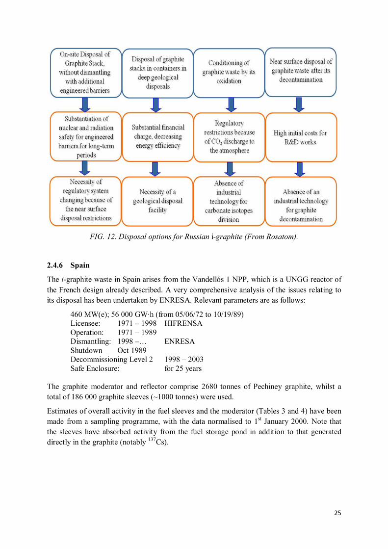
Rosatom identifies a number of possible variants for handling Russian graphite wastes, illustrated in Figure 12.
No formal graphite waste management decision has yet been made, with the authorities proposing lengthy periods of ‘safe storage’ for the majority of graphite stacks to allow shorter–lived isotopes to decay. The Russian work for the present CRP relates to the third and fourth columns of Figure 12.
25
FIG. 12. Disposal options for Russian i-graphite (From Rosatom).
2.4.6 Spain
The i-graphite waste in Spain arises from the Vandellós 1 NPP, which is a UNGG reactor of the French design already described. A very comprehensive analysis of the issues relating to its disposal has been undertaken by ENRESA. Relevant parameters are as follows:
460 MW(e); 56 000 GW·h (from 05/06/72 to 10/19/89) Licensee: 1971 – 1998 HIFRENSA Operation: 1971 – 1989 Dismantling: 1998 –… ENRESA Shutdown Oct 1989 Decommissioning Level 2 1998 – 2003 Safe Enclosure: for 25 years The graphite moderator and reflector comprise 2680 tonnes of Pechiney graphite, whilst a total of 186 000 graphite sleeves (~1000 tonnes) were used.
Estimates of overall activity in the fuel sleeves and the moderator (Tables 3 and 4) have been made from a sampling programme, with the data normalised to 1st January 2000. Note that the sleeves have absorbed activity from the fuel storage pond in addition to that generated directly in the graphite (notably 137Cs).

26
TABLE 3. MEAN RADIOISOTOPIC DATA FOR VANDELLÓS GRAPHITE FUEL SLEEVES AT 01/01/2000
Isotope
Proportion of
Total Activity
(%)
Mean Activity
(Bq/g)
3H 38.44 8.93E+04 14C 5.81 1.35E+04
55Fe 11.62 2.70E+04 60Co 17.22 4.00E+04 59Ni 0.27 6.25E+02 63Ni 25.31 5.88E+04
137Cs 0.16 3.79E+02 154Eu 0.19 4.35E+02 241Pu 0.29 6.82E+02
Total 99.31 -
The graphite pile will remain inside the reactor building in a safe enclosure for 25 years. The sleeves were extracted as described below and temporarily stored on site in 220 cubic containers of 6 m3 with the crushed graphite obtained from the standard separation process carried out in Vandellós 1. The total mass of graphite waste is 3500 tonnes: there are 98 cylindrical containers with the wires of the sleeves comprising 22 tonnes.
TABLE 4. MEAN RADIOISOTOPIC DATA FOR VANDELLÓS MODERATOR GRAPHITE AT 01/01/2000
Isotope Content
(%)
Mean Activity
(Bq/g)
3H 74.97 2.75E+05 14C 15.32 5.62E+04
55Fe 2.50 9.15E+03 60Co 3.65 1.34E+04 63Ni 2.39 8.77E+03
241Pu 0.19 6.89E+02
Total 99.02 -
One of the issues causing most concern with the i-graphite of Vandellós 1, in relation to the waste acceptance criteria at El Cabril, is the 14C and 3H activities, which exceed the total acceptable inventory of the El Cabril repository by factors of eight and two respectively.

27
The presently estimated activities of principal isotopes in the graphite, compared with the licensed capacity of El Cabril and the content of the wastes already disposed there, is shown in Table 5.
TABLE 5. INVENTORY ANALYSIS FOR EL CABRIL FOR THE FOUR PRINCIPLE GRAPHITE-DERIVED ISOTOPES
Isotope Permitted
Radiological
Inventory of
El Cabril
MBq
Activity
Disposed
At El Cabril
At 14/10/2011
MBq
Extent of
Permitted
Inventory
Currently
Used
%
Estimated
Graphite
Activity
MBq
Ratio of
Graphite
Activity to
Permitted Inventory
%
3H 2.0 E+08 3.10 E+06 1.57 4.22 E+08 211
14C 2.0 E+07 2.84 E+06 14.2 1.65 E+08 825
60Co 2.0 E+10 2.64 E+08 1.32 1.57 E+07 0.08
63Ni 2.0 E+09 9.13 E+07 4.57 5.41 E+07 2.7
It is established that the third dismantling stage of Vandellós 1 NPP will begin in 2028 and, before that date, the following issues have to be defined with regard to i-graphite:
• Methodology for the retrieval of the core graphite;
• Decontamination of graphite (reduction in 14C and 3H) in order to have available the possibility of disposing of i-graphite in the El Cabril repository. The percentage of decontamination for 14C would need to be 88%, approximately;
• The option to create an impermeable cover, by using a specific glass, of the pore system of graphite to minimise or make negligible the release of the volatile or soluble content;
• The possibility of increasing the 14C radiological capacity of the El Cabril inventory;
• Volume reduction of the crushed graphite. The current amount of the Vandellos 1 graphite, if it undergoes a crushed pre-treatment, would fill more than 800 concrete containers in the El Cabril Repository.
ENRESA, the Spanish radioactive waste management agency, is responsible for the management of the operations arising as result of the decommissioning of nuclear facilities. According to the Second Spanish National Report on the Joint Convention on the Safety of Spent Fuel Management and on the Safety of Radioactive Waste Management (October 2005), Spain possesses the infrastructure required for the management of spent fuel and radioactive waste from the administrative, technical and economic-financial points of view. Regarding the administrative issue, there is an organization, based on a relatively far-reaching and highly developed framework in keeping with the evolution of the international regulatory requirements, that contemplates and includes the main responsibilities of the different parties

28
involved in the process. Figure 13 shows the institutional framework in Spain for the management of spent fuel and radioactive waste.
FIG. 13. Institutional framework in Spain for the management of spent fuel and radioactive
waste.
The Spanish Government establishes the general lines of the national policy on the management of radioactive waste and spent fuel, including the decommissioning and dismantling activities at nuclear and radioactive installations, through the ‘General Radioactive Waste Plan’ (GRWP). This Plan is an official document drawn up by ENRESA and submitted to the Ministry of Industry, Tourism and Commerce (MITYC) in compliance with the requirements of the standards in force. It is required to be submitted to the Government by the MITYC and, following its approval, communicated to the Parliament.
The GRWP must contain the actions and technical solutions foreseen for the management of radioactive waste and spent fuel as well as the dismantling and decommissioning of nuclear, and where appropriate radioactive, facilities throughout the timeframe of the Plan, and the economic and financial measures foreseen for the performance of those actions. The GRWP currently in force is the 6th, which was approved in June 2006.
The organization and responsibilities for dismantling of nuclear and radioactive installations are legally defined. The responsibility for decommissioning is initially with the licensee itself which, prior to the granting of the corresponding authorization, undertakes the so-called pre-dismantling activities.
The licensee of the operating permit is responsible for conditioning the operating wastes generated during the operation of the plant, in accordance with the acceptance criteria of the disposal facility to which they are to be transferred. Secondly, the licensee of the facility must have unloaded the fuel from the reactor and from irradiated fuel storage pools or, otherwise, for having available a spent fuel management plan approved by MITYC, following a report from the Nuclear Safety Council (Spanish Radiation Protection and Nuclear Safety Authority,
GRWP: General Radioact ive Waste Plan
REGULATIONAND
LICENSING
PARLIAMENT GOVERNMENT
ENRESA
NUCLEARSAFETY
COUNCIL
MINISTRY OFINDUSTRY, TOURISM
AND TRADE
MINISTRY OFTHE
ENVIRONMENT
MINISTRY OFECONOMY AND
FINANCES
MINISTRY OFSCIENCE ANDINNOVATION
GENERALSECERETARY OF
ENERGY
NATIONALINDUSTRIALHOLDING
(SEPI)
NATIONAL RESEARCHCENTRE FOR ENERGY,ENVIRONMENT AND
TECHNOLOGY(CIEMAT)
WASTEPRODUCERS
CONTROL
20% 80%
REGULATIONAND
LICENSING
PARLIAMENT GOVERNMENT
NUCLEARSAFETY
COUNCIL
MINISTRY OFINDUSTRY, TOURISM
AND TRADE
MINISTRY OFTHE
ENVIRONMENT
GENERALSECERETARY OF
ENERGY
CONTROL
REGULATIONAND
LICENSING
PARLIAMENT GOVERNMENT
NUCLEARSAFETY
COUNCIL
MINISTRY OFINDUSTRY, TOURISM
AND TRADE
MINISTRY OF THEENVIRONMENT, RURAL AFFAIRS AND MARINE
GENERALSECERETARY OF
ENERGY
CONTROL
MINISTRY OFECONOMY AND
FINANCES
NATIONALINDUSTRIALHOLDING
(SEPI)
NATIONAL RESEARCHCENTRE FOR ENERGY,ENVIRONMENT AND
TECHNOLOGY(CIEMAT)
20% 80%
POLICY
(GRWP)

29
CSN). The contract between ENRESA and the NPP licensees, approved by the MITYC, establishes in greater detail the responsibilities of the licensee and the scope of the work to be performed by it in order to plan the dismantling to be performed by ENRESA.
The long term safety assessment of the disposal system, for radionuclide release, is directly linked with the concept of radionuclide retention properties of the different media considered (wasteform-condition material, container, cell, backfill, geosphere), that prevent or resist the migration of radioisotopes from the waste to the biosphere, requiring the behaviour of those barriers to be analysed in order to quantify the release of the radionuclides.
A “disposal unit” is the minimum object over which the WAC are applied, and it is comprised of the following components:
• Concrete container;
• Conditioned waste packages put inside;
• Mortar that fill the gaps between packages.
The concrete container is considered as a confining object due to the fulfillment of the retainable properties of annual fraction of activity release. For this purpose, transport properties analysis has been performed to quantify the effective diffusion coefficient, De, distribution coefficient, kd, permeability and hydraulic conductivity.
Waste packages also have to fulfill retention properties and leaching rates for those liquid wastes incorporated in cement, and diffusion values for those wastes conditioned using a mortar envelope. All these properties are required to be reported by the producers, and finally a quality control process is applied to verify the process complies with the WAC.
Additionally, the mortar that fills the gaps between packages is also supposed to meet the WAC requirement in relation to the retention properties.
The final described ensemble, termed “Disposal Unit”, is modelled in radionuclide transport processes involving water as a media. Therefore there are three barriers connected in series that oppose radionuclide release (Figure 14).
Finally, the engineering barriers play an additional and fundamental function in the middle and long term safety assessment of the repository:
• Multiple coating layers;
• Synthetic non permeable layer;
• Concrete slab layer over the cells;
• Concrete containers (disposal units);
• Layer of porous concrete;
• Synthetic non-permeable layer;
• Concrete slab layer under the cells;
• Control system of leakage.
Gas production is also considered by means of anaerobic corrosion of metallic containers of packages, water radiolysis and, to a lesser extent, by biological degradation of organic carbon. Gaseous radionuclide releases are much lower than releases into groundwater.

30
All barriers are considered in the analysis of the transport processes of radionuclides except for synthetic liners and the controlled system of leakage.
FIG. 14. Barrier system at El Cabril disposal centre.
On the other hand, for the scenario analysis of human intrusion after a surveillance period of 300 years, the most important concern with regard to WAC is the activity content of the wastes.
After the operational phase of the repository, the human intrusion scenarios are reversed, with potential radionuclide release to the biosphere.
The dose limits considered for the scenarios involved are in general 1 mSv/y and some added scenarios consider 0.1 mSv/y. The total number of scenarios considered after an initial period of 300–500 years is five.
Alpha emitters are low in the irradiated graphite, and strong gamma emitters (60Co mainly) are expected to be quite low after that period of surveillance. These considerations, along with the radionuclides discarded during thermal decontamination and the amount of irradiated graphite (3500 tonnes), make the doses produced by irradiated graphite in intruder scenarios equivalent to or lower than the doses caused by other wastes.
The scenarios are related to the construction of public building or residences and with agriculture activities. Exposure and inhalation doses are the general pathways, but ingestion is also taken into account.
Operational aspects have to be also taken into account, such as the handling operation, accident scenarios, dose limits for the workers, etc. Those issues are included in the safety analysis and define additional limitation in the repository.
Residuos y mortero relleno
Hormigón contenedor
Cobertura
Cobertura provisional Hormigón en masa
Losa superior de hormigón
Hormigón poroso Lámina impermeabilización RCI Losa inferior de hormigón
Zona saturada (B10)
Infiltración
Barrera (B4)
Barrera (B3)
Barrera (B0)
Barrera (B1) Barrera (B2)
Barrera (B2)
Barrera (B7)Barrera (B6)Barrera (B5) Barrera (B8)Zona no saturada
Barrera (B9)
Waste Packages and gap fill mortar
Barrier B4
Water flow
Disposal unit container
Barrier B3
Coating layers
Barrier B0
Synthetic layer
Barrier B1
Upper concrete slab layer
Barrier B2
Concrete slab lower part
Barrier B2
Porous Concrete
Barrier B5
Synthetic layer
Barrier B6
Non saturated layer
Barrier B9
Saturated layer
Lower concrete slab layer
Barrier B7Control system leakage
Barrier B8

31
As a result of the features described, Waste Acceptance Criteria have been developed for the El Cabril repository that perfectly fit the safety assessment analysis.
The basic structure of WAC is depicted in Figure 15, focusing on three main fields, namely ‘Non Radiological Criteria’ (organic content, exothermic issues, complexing agents, oils, substances that inhibit the mortar curing process…), ‘General Criteria’ (package identification, mass, volume, dose rate, nature of the waste, package degree of filling, non-free liquids…) and ‘Quality Criteria’ (mechanical strength, release rate and radioactivity content).
FIG. 15. Basic structure of El Cabril WAC for L&ILW.
The generic WAC that have to be verified for i-graphite are as follows:
• Package identification to control the waste package inventory as it is established;
• Nature of the waste. There is a list of allowed waste forms for disposal;
• A final waste form is designed as a function of the waste form, due mainly to the imposed criteria of non–free liquids, mechanical strength and release limits;
• Package mass and dimension prescribed for handling in the repository;
• Package dose rate due to the limitations during operational issues in the disposal process and transport;
• Degree of filling of the package to avoid deliberate dilution and in consideration of structural behaviour of the packages when stacked;
• Transport requirements.
Special attention should be paid to the following WAC in respect of i-graphite:
• Activity quantification of the isotopes included in the inventory of El Cabril and verification of values. Consideration of waste category;
TYPIFIED HISTORICAL
GENERAL CRITERIA
LEVEL 1 LEVEL 1 LEVEL 2 LEVEL 2
NON RADIOLOGICAL CRITERIA
WASTE NATURE & WASTE FORM
SOLIDIFIED HOMOGENEOUS(Resins, E Concentrates, Sludge)
HETEROGENEOUS(Compactable, non compactable)
INMOBILISED (Cartridge filter, dried sludge, ashes)
QUALITY CRITERIA
�Act ivity limits
�Gap filling
�Pre_compactat ion
�Act ivity limits
�Strength
� Leaching
�Act ivity limits
�Mortar sleeve thickness
�Strength
�Diffusion

32
• All non-volatile radioisotopes have a good correlation, scaling factor, with a key nuclide, namely easy to measure isotope (60Co). Therefore it will be easy to infer the activity of difficult to measure isotopes of waste packages from the 60Co activity, but 3H, 14C and 36Cl do not have such a correlation, and alternative methods should be developed to characterize every waste package;
• Exothermic release of energy dependent upon the operational condition of i-graphite. Not expected for Vandellós 1 i-graphite;
• Compatibility analysis between graphite and mortar used normally in El Cabril, in order to verify the effects, if any, and the degree of influence on the WAC values of structural resistance and release properties;
• Mechanical properties of the wasteform. Surface disposal requires a structural resistance of the conditioned waste;
• Leaching values for radionuclides. Those leaching rate values have been calculated from the safety assessment analysis of El Cabril repository, taking account of different scenarios;
• Volume optimization. There is a requirement to optimize the volume of the current wastes to be disposed in El Cabril by compaction, evaporation, drying processes, etc.
It is therefore expected that the i-graphite will require a treatment process, with the following objectives and criteria to satisfy the WAC:
• Fulfillment of mechanical properties by the waste form itself. Mechanical properties are also required for conditioned waste in a surface repository due to structural issues;
• Reduce or make negligible the leaching rate. This is a very important issue for discussion within the regulatory body. Even if the leaching properties of non-treated graphite matrix fulfill the WAC, due to the large heterogeneity of the graphite, it can be difficult to defend this aspect when leaching rate is close to the limits. It is expected that leaching criteria are not fulfilled for contamination isotopes. Also the fast release fraction of volatile isotopes could be above the leaching rate limit of WAC. Leaching rates of 3H and 14C have to be evaluated for non-treated and treated graphite;
• Volume optimization. Crushed graphite has an apparent density of 0.5 to 0.7 g/cm3 in relation to the apparent density of the graphite of 1.8 g/cm3, approximately a factor 3 of volume could be saved. In case of doing nothing into this respect, an extra envelope of mortar would be required for structural and diffusion reasons, increasing the disposed volume.
It is clear that the quantity of irradiated graphite in Spain does not justify the building of a specific repository for this material, and therefore it is hoped that disposal at the El Cabril facility meeting WAC requirements will be possible. To achieve this goal, specific treatments will have to be applied to the i-graphite, for example:
• A thermal decontamination process under a controlled non-oxidizing atmosphere. This process will remove the labile fraction, which will be trapped

33
in secondary waste. The 14C and 3H which would be released in the process needs to be evaluated;
• An impermeable vitreous coating applied to the thermally decontaminated graphite. The final product must be a very stable material, with a negligible or non-existent release rate of radionuclides and with good mechanical properties.
If the thermal decontamination does not achieve the decontamination factor required to achieve disposal of the i-graphite in El Cabril, an analysis for a new assessment of the radiological capacity of El Cabril could be performed with the new 14C release rate of the final glass-coated wasteform, which would be the majority of the 14C contained in the repository, and a subsequent Regulatory Council study and approval would be required.
2.4.7 Switzerland
Disposal of radioactive materials in Switzerland is governed by regulation ‘HSK B05’ [42] and the final disposal of such wastes is governed by the organization Nationale Genossenschaft für die Lagerung von Radioaktiven Abfallen (NAGRA), although specific activity limits are laid down in the ‘Swiss Radioprotection Ordinance’ (SRO). The material for disposal must be specified in terms of nuclide inventory, material composition, technical packaging arrangements, etc.: this eventually leads to a certificate for disposal of the material by NAGRA. At this stage, an application is then made to the Swiss Federal Nuclear Safety Inspectorate to approve the procedure. Only after receiving that approval can any conditioning procedure commence. The current position is that the wastes are then stored in the Federal Interim Storage Facility awaiting final disposal at some time in the future: there is no final repository in Switzerland at present.
The quantities of graphite waste from the Paul Scherrer Institute reactors are quite small, although the institute hosted three reactors, two of which contained quantities of graphite. All of the graphite has passed the above procedures. Radioactive materials other than graphite from these two reactors were disposed of in standardized containers with an internal volume of 2.75 m3 and an overall volume of 4.5 m3 [43].
The DIORIT and PROTEUS reactors at the Paul Scherrer Institute were research facilities in which the graphite received only a very small irradiation dose. Consequently, the quantities of critical isotopes as discussed in previous sections were in all cases except one very low compared with exemption limits defined by SRO. In consequence, a novel method of incorporating the graphite into an immobilizing mortar was developed, which is described more fully in the technical sections of this document. In the case of 36Cl for the DIORIT reactor, the quantities were found to be well above the exemption limits, justifying research into and commitment to a conditioning process ahead of incorporation into the mortar and thus participation in this CRP.

34
2.4.8 Ukraine
A ‘preferred’ decommissioning strategy for Chernobyl RBMK Units 1 – 3 envisages safe storage until around 2045 with dismantling complete by 2064. At that point, the graphite will be packed in 200-litre containers and placed into an existing temporary storage facility alongside other wastes, without grouting. Separately, work is in progress on suitable grouts for a final disposal to a repository.
According to estimates, the graphite stack and graphite elements of channels may account for as much as 80% of the total amount of radioactive waste. However, these estimates are to a large extent dependent on the impurity content of the graphite. The waste inventory of irradiated graphite waste of Chernobyl NPP is approximately 5687 tonnes (3732 m3) in ChNPP Units 1-3 whilst the residual highly contaminated graphite3 in the sarcophagus of Unit 4 is approximately 700 tonnes.
In compliance with the requirements of the regulatory documents, the composition and activities of radionuclides accumulated in structural materials and structures during the operation of the NPP power unit must be evaluated before its removal from service. The first to be examined will be the main sources of radionuclides, which are the structures of the reactor, especially the graphite stack and other graphite elements.
No specific waste acceptance criteria have been defined: however, work is in progress on this issue by SNRCU in compliance with international standards as expressed in ICRP 60 [44] which defines acceptable public and operator doses.
2.4.9 United Kingdom4
The Nuclear Decommissioning Authority (NDA) has been charged with implementing UK Government policy for the long-term management of higher activity radioactive waste. The UK’s significant irradiated graphite inventory is part of the inventory of Intermediate Level Waste (ILW) and Low Level Waste (LLW) [45, 46]. Graphite waste represents approximately 30% of the UK volumetric inventory of ILW and arises from two principal sources:
• A significant proportion of ‘reactor decommissioning wastes’ will be graphite and will arise when reactors are decommissioned; this is mostly reactor core wastes;
• Waste graphite also arises from spent fuel management operations and there are further arisings from the retrieval of legacy wastes at some sites. This type of graphite waste is predominantly derived from fuel sleeves.
The NDA assumes responsibility for nuclear sites when they cease operation. In their strategy published in March 2011, and the 2009/12 NDA Business Plan, NDA made a commitment to
3 This so-called 'emergency' graphite exhibits certain different properties from non-accident material.
4 Disposal of radioactive wastes in Scotland is the subject of different decisions and legislation originating from
the Scottish Parliament in Edinburgh, and a different policy is being implemented compared with that for the rest of the United Kingdom (England, Wales and Northern Ireland). All references to the UK’s planning for a geological disposal facility in this present report do not necessarily apply to wastes originating from Scottish nuclear sites.

35
explore management and treatment options for reactor graphite waste. This reflected Recommendation 8 from the Committee on Radioactive Waste Management (CoRWM) on reactor decommissioning wastes (made in 2006) and the related response from Government (both reproduced below), which recognized the need to examine alternative options for all wastes arising from reactor decommissioning. Most of the reactor core graphite waste will not arise until 70-100 years after fuel has been taken out of the reactors.
CoRWM Recommendation 8:
In determining what reactor decommissioning wastes should be consigned for geological disposal, due regard should be paid to considering other available and publicly acceptable management options, including those that may arise from the low level waste review.
UK Government Response:
Government accepts this recommendation. The NDA will review whether a safety case could be made for other non-geological disposal of reactor decommissioning wastes, including on-site, or near-site, disposal in order to minimise transport. In doing this it will take account of the outcome of the Government’s Low Level Waste management policy review, as well as public and stakeholder views. The NDA will use the outcome of these reviews, which will be published, in developing its outline geological disposal implementation plan.
In response to the above statements, NDA launched the Reactor Decommissioning Wastes (RDW) project in 2009 to build on NDA’s support for the EU CARBOWASTE project. The RDW project was designed to examine the potential benefits and costs of options for the alternative management of reactor decommissioning waste, whilst also considering the implementation of the waste hierarchy. It focused on Magnox reactors in the NDA estate, but in considering the position with regard to the large volume estimate of waste graphite, also takes account of the eventual decommissioning of graphite moderated Advanced Gas Cooled Reactors (AGRs) owned by EdF Energy.
This work is part of the NDA Higher Activity Waste (HAW) strategy development programme. The HAW strategy objective therefore provides context for the work:
• ‘To treat and package HAW and place it in safe, secure and suitable storage facilities until it can be disposed of, or be held in long-term storage in the case of a proportion of HAW in Scotland’
An update was given on this ongoing strategic work in the 2011 NDA document Reactor Decommissioning Update – Summary of Options for Waste Graphite, where NDA outlined further work that was necessary to develop a strategic position. A full report on the findings of the further work that has taken place since the update was published is annexed to the TECDOC.
The graphite programme is a component of the overall HAW strategy and interfaces with the following topic strategies:
• Low Activity Waste (because of the potential for use of the Low Level Waste Repository (LLWR) or a similar facility for disposal and learning from the LLWR Environmental Safety Case (ESC)).

36
• Decommissioning (because that could affect the rate and form of graphite arisings).
• Transport and logistics (because of the potential need to move waste between sites).
The baseline strategy for reactor graphite is to dismantle reactor cores following a period of quiescence (typically 85 years) and package the graphite for disposal. Disposal in a Geological Disposal Facility (GDF) is the planned end point for the packaged waste in England and Wales. The Scottish Government Policy is that the long-term management of higher activity radioactive waste should be in near-surface facilities; and that those facilities should be located as near to the site where the waste is produced as possible/practicable. Developers will need to demonstrate how the facilities will be monitored and how waste packages, or waste, could be retrieved. All long-term waste management options will be subject to robust regulatory requirements [52].
Notable arisings of operational graphite waste (primarily components of fuel elements) are present at three sites within NDA’s estate: Berkeley, Hunterston ‘A’ and Sellafield. Work on operational graphite waste arisings has therefore focused on these three sites. The baseline strategy for the management of this graphite is to retrieve it, condition (either promptly or following a period of containerized storage) and package it in containers suitable for eventual disposal. The waste packages will be stored on-site prior to their eventual disposal to a future facility.
By drawing on UK and overseas experience, Radioactive Waste Management Limited (RWM) has developed illustrative geological disposal concept examples that are relevant to the UK context, inventory and available geological environments. These illustrative examples are all based on the principle of passive safety provided by a combination of engineered barriers designed to complement the natural barrier provided by the geological environment. The system of multiple barriers will ensure that the radioactivity in the wastes is sufficiently contained so that regulatory requirements are met and that exposures resulting from any releases to the surface will be as low as reasonably achievable and, in any event, less than a small fraction of the exposures everyone receives each year from naturally occurring sources of radioactivity in the environment.
The implementation of a GDF for higher activity radioactive wastes in England and Wales requires RWM to demonstrate its confidence that such a facility would be safe, during both the operational period and after it has been sealed and closed. As part of that process, RWM has developed the Disposal System Safety Case (DSSC) [47], the prime purpose of which is to demonstrate that a GDF can be implemented in a safe manner and in such a way that would meet all regulatory requirements. As implementer and future operator of a GDF, and therefore as the ultimate receiver of waste for disposal, RWM will be responsible for the production of waste acceptance criteria for the facility. While plans for the construction of a GDF remain at an early stage, the information necessary to define WAC is not available. In the meantime, and as precursor to the final WAC, RWM produces generic specifications for packaged waste.

37
A key purpose of the publication of these ‘packaging specifications’ is to provide a baseline against which the suitability of plans to package waste for disposal can be judged. By providing such a baseline, the holders of radioactive waste are assisted in the development and implementation of such plans by providing confidence that the resulting waste packages would be compatible with the anticipated needs for transport to and disposal in a GDF.
In 2012 RWM published a Generic Waste Package Specification [48], the purpose of which is to define high-level generic requirements for waste packages containing all categories of higher activity waste which will be subject to geological disposal. It represents the highest level document in a hierarchy of packaging specifications which have been produced to satisfy the needs of all who have an interest in geological disposal in general and the packaging of waste in particular.
RWM has established a methodology for the production of Generic Specifications for waste packages containing defined categories of waste (e.g. low heat generating waste, high heat generating waste etc.) The methodology ensures that each such specification is founded on:
• The definition of a disposal concept for the waste;
• The designs of the systems for transport and disposal developed to meet the relevant Disposal System Specification (DSS) [49];
• Safety cases for transport, disposal facility operations and the post-closure period; and
• Regulations for the storage, transport and disposal of radioactive material.
Each Generic Specification also provides the basis for the definition of ‘Waste Packages Specifications’ which define the requirements for waste packages manufactured using standardized designs of waste containers that have been shown to be suitable for the packaging of a particular type of waste for geological disposal.
Currently Generic Specifications exist for two broad categories of waste:
• Waste packages containing low heat generating waste (which includes ILW and which would apply to wastes such as irradiated graphite) [50];
• Waste packages containing high heat generating waste (which comprises mainly vitrified HLW and nuclear fuel).
The RWM disposability assessment process exists to support UK Site Licence Companies (SLCs) that wish to condition and package higher activity wastes – including irradiated graphite – in a form that is compatible with plans for the implementation of a GDF. It is also used to support the ongoing development of the safety cases (transport, operational and environmental) for geological disposal by the provision of information regarding the numbers and properties of the waste packages that will eventually require transport to and disposal in a GDF. The process was originally developed back in the 1980s primarily as a means to assist site operators to convert intermediate level wastes into passive safe and disposable forms. The assessment process continues today to provide the same service to SLCs albeit in a far
38
more structured and rigorous way and in line with regulatory expectations for the long term management of all higher activity waste.
The disposability assessment process also plays an important role in underpinning the DSSC, as it provides confidence that the safety cases, which are based on generic assumptions regarding the wastes and the form of packaging, are compatible with ‘real’ waste packages being developed by industry. Through application of the disposability assessment process RWM, together with the site operator and regulators, gain confidence that proposed waste packages will ultimately be compliant with requirements for transport and disposability. This may involve relevant parties together considering different packaging approaches and determining which combination of barriers (wasteform and waste container) best meet the needs for waste retrieval, processing, storage and ultimately, disposal. This is important as it gives confidence that packaging strategies, and ultimately investment decisions, are soundly based and will result in waste packages designed in line with transport and disposal requirements. Confidence in the developing DSSC is built up over time through a periodic review process by which the validity of disposability assessments are maintained by ensuring that they remain up to date and consistent with the DSSC as concepts for geological disposal evolve towards an operational GDF.
The main purposes of disposability assessments are therefore to:
• Give confidence to site operators (and waste owners) that the implementation of their proposals for waste packaging will result in waste packages that best meet the needs for processing and storage whilst being compliant with the eventual needs for transport to and disposal in a GDF;
• Provide confidence that the disposal concepts considered within the DSSC will be appropriate for the wastes they will be expected to cover; and
• Permit the identification of wastes that could challenge current disposal concepts and allow early consideration of what changes may be required to these concepts to permit the wastes to be accommodated.
Since the mid–1980s, waste producers in the UK have made significant investment in waste retrieval and packaging plant as a means of ensuring that such wastes are rendered passively safe and suitable for disposal in a GDF. Historically Nirex was responsible for the assessment and endorsement of the suitability of waste packagers’ proposals to package waste for these needs, a responsibility assumed by the NDA's Radioactive Waste Management Directorate (RWMD)5 in 2007 following Nirex’s incorporation into the NDA.
The assessment of the disposability of waste packages was originally carried out by way of the ‘Letter of Comfort’ (LoC) assessment process which, following two decades of use and development, has evolved into the current LoC disposability assessment process [51].
5 Note that in April 2014, RWMD was replaced by Radioactive Waste Management Limited (RWM) (http://www.nda.gov.uk/rwm), a wholly–owned subsidiary of the Nuclear Decommissioning Authority

39
The role played by the disposability assessment process is summarised in Figure 16, which also illustrates the relationship between the process, the DSS, the safety and environmental assessments and the packaging specifications. In practice the process requires the waste packager to provide information to RWM regarding the wastes and the conditioning processes, and any pre-treatments that are proposed to render the wastes suitable to for geological disposal. Following assessment, RWM provides detailed advice on transport and disposability issues and where necessary to ultimately complete the assessments, request further information or flag the need for further development and/or research.
In undertaking disposability assessments RWM determines whether packaged wastes will have characteristics compliant with the safety case requirements for transport to, and operations at a GDF, and ultimately whether the wastes could be accommodated within a GDF post-closure safety case, i.e. that the packages are ‘disposable’. The main output of the assessment is an Assessment Report detailing the work undertaken and which may be accompanied by a Letter of Compliance (LoC). The LoC is simply a statement to the effect that the waste package as described in the submission has been assessed and found to be compliant with the requirements for transport and geological disposal as currently defined.
Figure 16 illustrates that the disposability assessment process has the potential to allow site operators and RWM to iterate through the assessment cycle – this is particularly useful where the operator and/or RWM recognises that there would be benefit in exploring alternative packaging options, particularly where there is a need to balance potentially conflicting requirements from site safety cases and disposal safety cases.
Regulators’ guidance [52] requires that waste packagers (Site Licensees) produce a radioactive waste management case (RWMC) which includes reasoned argument why packaged waste will be disposable – the disposability assessment and accompanying LoC will provide an important component of such a case.

40
FIG. 16.Summary of the UK disposability assessment process.
It will be noted that, for the UK, there are no waste assessment criteria presently specifically defined for graphite, nor is there a Generic Specification for such waste. The assessment of the disposability of proposals to package graphite for disposal would take place against the Generic Specification for waste packages containing low heat generating waste [50].
Alternative destinies for all graphite waste have been considered in response to CoRWM Recommendation 8. A number of high-level strategic options for its management were laid out in the 2011 update on graphite:
• Option 1 – Manage all graphite waste as ILW and ensure the geological disposal facility caters for the large volumes of material. This is the baseline option for England and Wales.
• Option 2 – Condition graphite waste to enable disposal at LLWR Ltd.
• Option 3 – Condition LLW and/or ILW graphite waste to remove most of the contamination and release as “exempt waste” or reuse the graphite where possible.
• Option 4 – Separate disposal facility (or facilities) for graphite wastes, including a near surface disposal option and may include a pre-treatment step. This option would support Scottish Government’s HAW long term management Policy and the development of its implementation strategy.
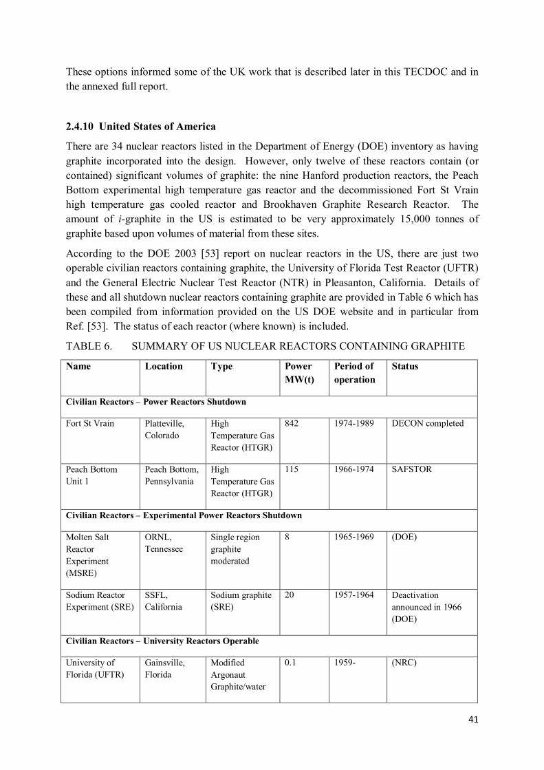
41
These options informed some of the UK work that is described later in this TECDOC and in the annexed full report.
2.4.10 United States of America
There are 34 nuclear reactors listed in the Department of Energy (DOE) inventory as having graphite incorporated into the design. However, only twelve of these reactors contain (or contained) significant volumes of graphite: the nine Hanford production reactors, the Peach Bottom experimental high temperature gas reactor and the decommissioned Fort St Vrain high temperature gas cooled reactor and Brookhaven Graphite Research Reactor. The amount of i-graphite in the US is estimated to be very approximately 15,000 tonnes of graphite based upon volumes of material from these sites.
According to the DOE 2003 [53] report on nuclear reactors in the US, there are just two operable civilian reactors containing graphite, the University of Florida Test Reactor (UFTR) and the General Electric Nuclear Test Reactor (NTR) in Pleasanton, California. Details of these and all shutdown nuclear reactors containing graphite are provided in Table 6 which has been compiled from information provided on the US DOE website and in particular from Ref. [53]. The status of each reactor (where known) is included.
TABLE 6. SUMMARY OF US NUCLEAR REACTORS CONTAINING GRAPHITE
Name Location Type Power
MW(t)
Period of
operation
Status
Civilian Reactors – Power Reactors Shutdown
Fort St Vrain Platteville, Colorado
High Temperature Gas Reactor (HTGR)
842 1974-1989 DECON completed
Peach Bottom Unit 1
Peach Bottom, Pennsylvania
High Temperature Gas Reactor (HTGR)
115 1966-1974 SAFSTOR
Civilian Reactors – Experimental Power Reactors Shutdown
Molten Salt Reactor Experiment (MSRE)
ORNL, Tennessee
Single region graphite moderated
8 1965-1969 (DOE)
Sodium Reactor Experiment (SRE)
SSFL, California
Sodium graphite (SRE)
20 1957-1964 Deactivation announced in 1966 (DOE)
Civilian Reactors – University Reactors Operable
University of Florida (UFTR)
Gainsville, Florida
Modified Argonaut Graphite/water
0.1 1959- (NRC)

42
Civilian Reactors – University Reactors Shutdown
University of California
Los Angeles, California
Educator, Graphite/water
0.1 1960-1984 License terminated in 1993 (NRC)
Iowa State University
Ames, Iowa Argonaut (UTR-10), Graphite/water
0.01 1959-1998 DECON (NRC)
North Carolina State University
Raleigh, North Carolina
Graphite/water 0.01 1960-1973 License terminated in 1983 (NRC)
Virginia Polytechnic Institute
Blacksburg, Virginia
Graphite/water (UTR-10)
0.1 1959-1984 License terminated in 1988 (NRC)
University of Washington
Seattle, Washington
Argonaut, Graphite/water
0.1 1961-1988 DECON (NRC)
Civilian Reactors – Research and Test Reactors Operable
General Electric Nuclear Test Reactor
Pleasanton, California
Light Water Reactor (LWR), graphite
0.1 1957- (NRC)
Civilian Reactors – Research and Test Reactors Shutdown
American Standard Inc.
Graphite/water (UTR-1)
- 1958-1960 Shipped abroad for exhibition purposes (NRC)
Argonne Low Power Research Reactor
ANL, Chicago, Illinois
Juggernaut, Graphite/water
0.25 1962-1970 (DOE)
Argonne Nuclear Assembly for University Training
ANL, Chicago, Illinois
Argonaut (CP-11), Graphite, water
0.01 1957-1972 (DOE)
Brookhaven Graphite Research Reactor
BNL, New York State
Air-cooled, graphite moderated (BGRR)
20 1950-1959 Decommissioning complete 2012
Chicago Pile 1, rebuilt as CP-2
ANL, Illinois Graphite (CP-2) - 1942-1954 Decommissioned and buried on site (DOE)
High Temperature Lattice Reactor
PNNL, Hanford, Washington
Graphite moderated (HTTR)
0.002 1967-1971 (DOE)
Oak Ridge Graphite Reactor (ORG)
ORNL, Tennessee
Graphite 3.5 1943-1963 (DOE)

43
Physical Constants Test Reactor (PCTR)
PNNL, Hanford, Washington
Graphite 0 1955-1972 (DOE)
Thermal Test Reactor No. 2 (TTR-2)
PNNL, Hanford, Washington
Graphite 0 1955-1972 (DOE)
Transient Reactor Test Facility (TREAT)
ANL, Illinois Graphite 0.12 1959-1994 (DOE)
UTR Test Reactor - Graphite/water - 1961-1963 (NRC)
Production Reactors – Materials Production Shutdown
B Reactor Hanford Site, Washington
Graphite 250 1944-1968 (DOE)
C Reactor Hanford Site, Washington
Graphite 650 1952-1969 (DOE)
D Reactor Hanford Site, Washington
Graphite 250 1944-1967 (DOE)
DR Reactor Hanford Site, Washington
Graphite 250 1950-1964 (DOE)
F Reactor Hanford Site, Washington
Graphite 250 1945-1965 (DOE)
H Reactor Hanford Site, Washington
Graphite 400 1949-1965 (DOE)
KE Reactor Hanford Site, Washington
Graphite 1850 1955-1971 (DOE)
KW Reactor Hanford Site, Washington
Graphite 1850 1955-1970 (DOE)
N Reactor Hanford Site, Washington
Graphite 4000 1964-1986 (DOE)
Production Reactors – Process Development Shutdown
Hanford 305 Test Reactor (HTR)
Hanford Site, Washington
Graphite 1944-1976 (DOE)
SR 305-M Test Pile
Hanford Site, Washington
Graphite 1953-1983 Test pile has been dismantled (DOE)
Standard Pile (SP/SE)
Graphite 1953-1979 (DOE)

44
There are two approaches to decommissioning in the US, depending upon whether the nuclear plants are within the commercial sector licensed by the Nuclear Regulatory Commission (NRC) or are managed by the US DOE. In the case of a plant under the jurisdiction of the NRC, three methods for decommissioning are available: DECON (immediate dismantlement), SAFSTOR (facility maintained to allow decay of radioactivity, later followed by dismantlement) and ENTOMB (entombment and monitoring). The DOE approach covers transition, deactivation, surveillance and maintenance and decommissioning.
The US radioactive waste classification system has two separate subsystems, one applying to commercial and the other to DOE waste. Radioactive waste from DOE nuclear operations is classified as HLW, TRU waste, LLW or mill tailings. Waste may also contain hazardous waste constituents. Waste with both radioactive and hazardous constituents in the US is called ‘mixed’ waste. LLW is classified in the commercial sector as Class A, Class B, Class C and Greater than Class C (GTCC) LLW. These classes are defined in NRC regulations with concentrations of radioactive material increasing from Class A through to GTCC. DOE manages waste from its operations using procedures and requirements comparable to those used by NRC for commercial waste.
Commercial and government facilities exist for LLW processing, including treatment, conditioning and disposal. Generators prepare LLW for shipment to licensed disposal. There are four active licensed commercial LLW disposal sites in the US (GTS-Duratek/Chem-Nuclear, Barnwell, South Carolina; DOE Hanford Site, Richland, Washington; Envirocare of Utah, Clive, Utah; WCS, Texas); however, none can accept GTCC LLW. Classification as ‘TRU waste’ exists only within DOE government (non-commercial) sector and applies to material from weapons production activities. The principal repository for TRU waste is the Waste Isolation Pilot Plant, a deep geologic repository, in New Mexico. The planned Yucca Mountain deep geologic repository, if licensed, would be used for the disposal of HLW from both sectors.
Decommissioning of US nuclear reactors containing graphite includes the dismantlement of the Fort St Vrain plant under DECON, the dismantlement of the SR 305-M Test Pile at Hanford (DOE jurisdiction), the decommissioning and burial on site of the CP-2 (formerly Chicago Pile 1 and under DOE jurisdiction) and the decommissioning of the Brookhaven Graphite Research Reactor, which was completed under DOE jurisdiction in 2012. The graphite from the Fort St Vrain and Brookhaven reactors is now stored on a DOE site. At present, the US has no plans for the treatment of irradiated graphite with disposal as Low Level Waste on DOE sites being the favoured approach.
2.4.11 Graphite Waste Acceptance Criteria: General Issues
It is clear from the foregoing that waste acceptance criteria for i-graphite vary widely. In certain cases, they are imposed by preconditions set when a facility was authorized and which are perhaps much too restrictive but equally are almost impossible to change for political or social (public opinion) reasons. This is particularly true for countries where the amount of i-graphite waste is rather limited – ca. few thousand tons – and thus does not justify building a

45
dedicated repository. For countries having larger amounts of i-graphite to deal with, such as UK, Russia, USA or France, specific disposal facilities can be considered but a thorough study is then of the upmost importance to balance technical, financial, social and safety criteria. However, in a majority of the cases addressed in this work, acceptance criteria are not yet defined before the planned disposal timescales, meaning that decisions have not yet been needed. In one case, it appears that their definition may await the results of the graphite characterization anyway.
It was never the intended purpose of this CRP to define any ‘general’ acceptance criteria. The combination of relevant factors in each Member State vary widely, and operate on a number of levels which are reviewed below:
• International Level o IAEA guidance and recommendations; o treaty obligations (e.g. moratorium on sea dumping, which was at one time
viewed as a favourable option for graphite disposal [54]); o public education / objective risk assessment;
• Member State (Local) Level o geology (e.g. a decision to place i-graphite inside a salt dome might inform the
estimates of release of 36Cl, an issue which is developed below); o population density (e.g. a Member State like Russia with vast areas with very
low population might be contrasted with the very high population density in the UK);
o local politics and public opinion (including issue of retrievability); o imposed timescales (e.g. the decision in France to dismantle UNGG reactors
swiftly might be contrasted with the UK decision to delay any dismantling for many decades).
• Site Factors o state of the graphite (damage, fuel contamination, whether stored under water,
etc.); o design (ease of dismantling); o availability of temporary storage.
Taking up the final point first, the desirability of removing graphite from an essentially safe containment (reactor pressure vessel) and placing it in temporary storage in steel storage boxes, as undertaken for the UK WAGR, might be questioned although, in that case, a demonstration that dismantling of intact graphite blocks from a reactor in an air atmosphere could be accomplished was an important achievement.
At present, as far as precise waste acceptance criteria are generally not defined yet, main constraints considered for i-graphite management focus on radionuclides inventory and release. In this regard, most of the CRP participating countries have addressed a specific interest for tritium and 14C characterization in i-graphite which are respectively in most cases the main short lived and long lived radionuclides in terms of activity. They are also volatile species which implies specific restrictions at least for the operational phase of disposal facilities. Lastly, they may be quite mobile depending on their speciation, which requires

46
specific characterization studies. For RBMK reactors, alpha emitters and fission products contamination is also of interest because of fuel leakage problems during reactors operation. 36Cl behaviour has mainly been studied in France where it is considered to be one of the main contributors to the long-term radiological impact of graphite waste disposal due to its very long lifetime and its mobility under disposal conditions. However, it is possible that the issue of very long lived radionuclides such as 36Cl but also 129I, 41Ca or 10Be could have to be more precisely addressed for countries considering surface or near-surface facilities for i-graphite waste disposal. Currently, it seems indeed that such radionuclides are poorly characterized, whether their inventory or their behavior under disposal conditions.
On the whole, three principal disposal routes have been investigated by CRP participants and are indicated in Figure 17:
• Geological disposal (i.e. several hundreds of metres underground) is probably the least restrictive outlet for i-graphite waste in terms of WAC but could also be the most expensive one. Moreover, i-graphite activity does not necessarily require such an in-depth disposal. Therefore, it is often not considered as a management route for i-graphite or is viewed as the last option in case other management solutions have failed. Exceptions concern in particular Russia for high level i-graphite and Germany which has already identified a suitable disposal site (KONRAD, -800 – -1200 m) but for which operational requirements may imply previous i-graphite treatment or immobilization;
• Currently, the most common outlet investigated for i-graphite is surface or near-surface disposal (Spain, France, Lithuania…). However, this generally implies more rigorous constraints in terms of radiological capacities and leach rates due to shorter pathways to external environment and lower residence times. It explains current interest for decontamination and immobilization techniques. Sorting (piles vs. sleeves) prior to disposal is also sometimes considered as a way to fit to radiological restrictions;
• Lastly, although rather scarce, some alternative options propose either to decommission graphite waste if below clearance levels (Switzerland) or to inject it deep underground after previous treatment processes. However, the latter raises strong regulatory constraints and is, for the time being, not supported by national management agencies.

47
FIG. 17.Destinies for irradiated graphite waste considered in this CRP.
Assessing the impact of a repository based upon a presumption of its contents and an incomplete understanding of transport, migration and uptake pathways is an inexact science, and indeed waste authorities generally accept this too, indicating a need for taking into account uncertainties and for periodic revision of assessments in order to accommodate improving understanding and better characterization techniques. Arguments presenting the benefits of assessing risk in the context of those from other ‘everyday’ activities are presented in two publications from the UK Royal Society of Chemistry [55, 56]. The issues covered include natural radioactivity (which is effectively excluded from consideration), other industrial processes generating radioactive release (such as fossil-fuel burn, mining activities, etc.), alongside the risks posed by other industrial activity and everyday activity. A viewpoint on this topic comes from a bio-ethicist at the University of Detroit, USA, Dr. Margaret Maxey. Her view is that the application ‘linear, no-threshold’ (LNT) theory of radiation dose, which is the basis of current radiation exposure regulations, is counter-productive, a view also expressed by the late Ted Rockwell to a US senate committee and one shared by the late Prof Bernard Cohen of The University of Pittsburgh [57].
In the context of defining WAC, it is important to review carefully the potential migration of radioactive atoms (particularly long–lived β–emitters) through the geosphere and biosphere. This relates particularly to the chemical form of the active species, and signals an extremely important part of the characterization of i-graphite (Section 4.4, where 36Cl is discussed in detail as an example), since it is important that migration data relevant to the correct chemical

48
form are employed in assessments of the potential movement of the material away from a breached repository.
When incineration of the graphite is considered, it is the acceptability of the release of 14C into the atmosphere which is the primary concern. France has previously constructed and successfully operated a pilot plant for incineration [58] and made a preliminary analysis of the 14C emissions from such a plant in comparison with production from reactor operations [59]. Russia is currently commissioning a similar pilot plant and, in the specific instance of the contaminated graphite from the production reactors at the Siberian Chemical Combine, has published a detailed analysis of the creation and distribution of 14C in the graphite [60].
The concerns about potential releases of 14C from incinerators and indeed from repositories over long timescales are represented by its long half–life, are again its chemical form and the consequential environmental impact (take up by plant life, concentration of 14C-enriched gases, etc). In treatment options which might release 14C to atmosphere it has long been known that the impact on global population dose would be minimal [61] against a background of the high rates of production of ‘natural’ 14C in the upper atmosphere, and that any problems would be confined to local population doses adjacent to incineration plant: more recent work [62] has confirmed this and suggests specific methods of capturing the 14C as (for example) barium carbonate. A similar review of the potential of pyrolysis methodologies has been made [63]. Russian studies have also evaluated the potential impact of 14C from graphite incineration on the adjacent land and vegetation [64], work which also makes reference to studies of capture using barium hydroxide as early as the 1960s [65]. Nonetheless there has been a reluctance to address the opportunities presented by these technologies until recently: the latter has been proposed by UK participants to this CRP and indeed very recently tested on French graphite by Studsvik Inc on behalf of EdF.
The level of control and concern over 14C should also be considered against two other yardsticks: the amounts released from operational carbon dioxide cooled graphite moderated reactors during their lifetime, which are reported and represent surprisingly large amounts [66], and against the large amounts of natural 14C (and indeed other radioisotopes) emitted in power-plant stacks: the quantities are huge, with China, as an example, currently burning 10 000 000 tons coal per day to generate electricity.
Advantage could be taken of the Suess effect [67] whereby the 14C content of fossil fuel is below the present natural abundance, in order to ad–mix off gases from potential graphite treatments for disposal, such as in carbon–capture schemes. In addition, there is a potential market for 14C–labelled products, which could be tapped as a motivation for recovery of 14C from nuclear graphite.
For completeness, we also note here the investigations related to the disposal of HTR fuel, in which fuel particles have been in graphite–like material. The recent CARBOWASTE project has investigated the separation and treatment of this material in detail: earlier, a variety of processing options for the intact fuel, with recovery of isotopes, have been investigated [68-70]. A hybrid technique in which the graphitic material is oxidized in combination with molten carbonate fuel cells has also been proposed [71].
49
A number of examples have been given in this sub–section of reasons why the ideology of graphite waste disposal should be kept under constant review and, where necessary, challenged or updated. In a number of cases, information which has now been superseded or improved upon has been retained in critical arguments for or against certain courses of action in disposal of the graphite and carbonaceous materials. In principle, there are opportunities for significant savings of money and time if the latest available technologies are kept in mind and considered alongside the established plans and proposals for i-graphite disposal.

50
3. ORGANIZATION OF CRP WORK PROGRAMME
Graphite is a complex inhomogeneous material and therefore generalizations about its behaviour during irradiation and its final condition are to be avoided. The source of material and its irradiation history are key factors which will determine the ultimate condition of the material, the quantity and location of radionuclides within the matrix, and the preferred options for its management.
Methods for the dismantlement of graphite cores include individual block removal and destructive, excavation-type processes. A period of in-reactor storage could reduce doses to operators by allowing the radioactive decay of shorter lived radionuclides. Underwater retrieval could reduce dust and doses to operators but would generate aqueous waste that would require management. Segregation may be an option either during the retrieval process or during packaging after retrieval to separate different waste forms for treatment or disposal.
Partial decontamination by heat treatment and oxidation could offer credible options. Aqueous chemical treatment requires harsh environments which will necessitate careful process design but other chemical treatments such as steam reformation with off-gases incorporated in future carbon sequestration programmes could be more readily implemented. Intercalation processes using organic solvents may also be an option; however, decontamination by such processes generates secondary waste which will require management.
A range of waste package types and encapsulants are available for the retardation of radionuclide releases at disposal sites. The performance of waste packages has been investigated for a range of generic case geologies, but specific assessments will be necessary when final disposal sites have been selected. It may be possible to safely dispose of irradiated graphite wastes in the same vaults as other intermediate level wastes though there are benefits in separating large quantities of graphite.
The feasibility of recycle and reuse of irradiated graphite has also been considered, although there is unlikely to be a sufficient market for significant quantities of irradiated graphite.
Within this general framework, the work programmes undertaken by the participants to the present CRP may be broadly classified into four general areas of research defined by formal IAEA definitions [72]:
• characterization of the material: 'the determination of the physical, chemical and
radiological properties of the waste to establish the need for further adjustment,
treatment, conditioning, or its suitability for further handling, processing, storage or
disposal'. In this TECDOC this specifically covers work on graphite structure, the location of radioisotopes of interest, the chemical form of those isotopes, etc.);
• processing and treatment of the material: 'processing' is defined as 'any operation that
changes the characteristics of waste, including pretreatment, treatment and
conditioning', whilst 'treatment' includes 'operations intended to benefit safety and/or
economy by changing the characteristics of the waste'. Three basic defined treatment objectives are: volume reduction, removal of radionuclides from the waste and change of composition. It is implicit within these definitions that treatment may result in an

51
'appropriate' waste form. In this present work, this covers the treatment of graphite wastes to reduce activity levels or to condition the material in other ways, and also considerations of the initial dismantling methodology);
• immobilization: 'conversion of waste into a waste form by solidification, embedding
or encapsulation for the control of radioisotopes' (by reducing the potential for migration or dispersion of radionuclides during handling, transport, storage and/or disposal); and
• disposal options: included here is a specific definition of 'conditioning': 'those
operations that produce a waste package suitable for handling, transport, storage
and/or disposal'. Conditioning may include the conversion of the waste to a solid waste form, enclosure of the waste in containers, and, if necessary, providing an overpack.
The breakdown of the i-graphite management task is clearly complex but, in all cases, these operations contribute to the prime CRP objective of investigating treatment options for i-graphite in order to meet waste acceptance criteria (where they exist) – or to assist in their definition. Reference to the approach of the CARBOWASTE project is useful here: a consensus was achieved amongst their participants on twenty four potential options for the management of i-graphite, which are shown in Table 6 [73]. These options address the complete life cycle: in-reactor storage, conditioning, retrieval and treatment to final disposal.
TABLE 6. CARBOWASTE OPTIONS CONSIDERED FOR I-GRAPHITE ASSESSMENT
Option No. Description 1 Encapsulation and deep repository 2 Size reduce graphite for minimised waste package volume; local immobilization 3 Minimum processing 4 Deferred start with remote retrieval 5 Deferred start with manual retrieval 6 Minimum processing with deferred start 7 Alternative retrieval and graphite form in package 8 Alternative retrieval and repository 9 Interim storage and repository 10 Alternative retrieval, encapsulation and intermediate storage 11 In-situ treatment and near-surface repository 12 Ex-situ treatment and near surface repository 13 Gasification and isotopic dilution with conventional fossil fuel CO
2
14 Gasification and isotopic dilution with conventional fossil fuel CO2 as a result of sequestration
15 Gasification and isotopic dilution by dispersal as CO2 in the sea
16 C-14 re-use 17 C-14 re-use with no isotope separation 18 Graphite re-use for nuclear application only 19 In-situ entombment 20 Waste volume reduction and emission to atmosphere 21 Make use of graphite as inert filler, removing the need for some encapsulation 22 Immobilise in medium impermeable to 14C 23 Chemically bind 14C 24 Interim storage of raw waste (25 years) then encapsulation and disposal in an interim
repository

52
The key findings from the analysis were :
• Option 10 (Alternative retrieval, encapsulation and intermediate storage) has the highest associated costs due to the continual replacement of surface stores.
• Option 19 (in-situ entombment) has the lowest costs due to the lack of any construction stages.
• Gasification options (Options 13, 14, 15 and 20) and re-use options (Options 18 and 21) have a lower costs due to a fraction of the 14C being diverted elsewhere (with less i-graphite requiring consignment to a repository) or to a near-surface repository.
As may be seen from Table 7, each of the four basic categories of investigation is adequately covered within the present CRP, with some programmes spanning more than one of them. It is important to underline that management of secondary waste generated by treatment processes has not been addressed by CRP participants in their projects although it is a key issue when considering waste treatment processes.
TABLE 7. GENERAL BREAKDOWN OF RESEARCH AGREEMENTS AND CONTRACTS UNDER THE CRP CH = Characterization, PR = Processing, IM = Immobilization, DI = Disposal
Country, organization, and researchers involved
Research focus
CH PR IM DI
China. Tsinghua University, INET, Li Junfeng
Disintegration of Graphite Matrix from the High-Temperature Gas-Cooled Reactor Fuel Elements
France. Christine Lamouroux (CEA), Gerard Laurent (EdF), Laurence Petit (Andra)
Characterization of Radionuclides in Graphite Wastes
Germany. FZJ, Werner von Lensa
CARBODISP. Treatment of Irradiated Graphite to Meet Acceptance Criteria for Waste Disposal.
Germany. FNAG, Johannes Fachinger
Graphite as a Matrix Material
Lithuania. INPP. Alexander Oryšaka
Integration of Waste Management Features with Plant Dismantling
Lithuania. LEI. Ernestas Narkunas, Povilas Poskas
Treatment Requirements for Irradiated RBMK-1500 Graphite
Russia. VNIINM, Vladimir Kascheev, FGUP RADON, Olga Karlina
Methods of Irradiated Graphite Treatment – Characteristic Properties of Irradiated Graphite
Spain. ENRESA, Jose Luis Leganes Nieto
Measuring Techniques for 36Cl, 99Tc and 129I in Graphite, and Compatibility Tests to Meet Acceptance Criteria
Switzerland. PSI, Hans F. Beer

53
Determination of Long lived Radionuclides with Special Emphasis on Reactor Graphite
Ukraine. IEG, Boris Zlobenko
Investigation on the Conversion of Irradiated Graphite from the Decommissioning of Chernobyl NPP into a Stable Waste Form acceptable for Long-Term Storage and Disposal
United Kingdom. NDA, Simon Norris
Progression of UK Strategy Regarding Options for Long-Term Management of Irradiated Graphite
United Kingdom. The University of Manchester, Abbie Jones, Tony Wickham 14C and 3H removal from UK Graphite Waste
United Kingdom. University of Sheffield, Russell Hand
Development of Composite Materials to Utilise and Dispose of Waste Irradiated Graphite
United Kingdom. Bradtec, David Bradbury, Hyder/Bradtec, Jon Goodwin, Studsvik UK, Maria Lindberg, Costain, Terry Tomlinson, with Arbresle Ingéniere (France), Laurent Rahmani
Retrieval Demonstration – Novel Methodology, Efficacy of Gasification, Concept Design of CO2 Delivery System
Feasibility and Suitability of the Injection of Irradiated Graphite as an Aqueous or Oily Suspension or Foam into Confined Geological Formations
Chlorine Speciation
United Kingdom. NNL. Martin Metcalfe, Anthony Banford
Investigation into Aspects of the Production and Disposition of Carbon-14 in Magnox Reactor Graphite Cores
United States. Idaho State University, Idaho National Laboratory, Mary Lou Dunzik-Gougar
Characterization and Treatment of Carbon -14 in Irradiated Graphite
These contributions can be conveniently represented by the following diagram indicating differing management strategies (Figure 18):
Management options Investigated within
the CRP by:
• PSI (Switzerland*)
• Bradtec/Hyder/Studsvik UK/Costain (UK)

54
• Enresa (Spain*)
• PSI (Switzerland*)
• FZJ (Germany*)
• FNAG (Germany)
• EdF/CEA/Andra (France*)
• NDA (UK*)
• University of Sheffield (UK)
• INPP & LEI (Lithuania)
• Russia
• NNL (UK)
• EdF/CEA/Andra (France*)
• UoM (UK) • Idaho State University
(USA) • Radon (Russia) • Tsinghua University
(China) • INPP & LEI
(Lithuania*) • Bradtec/Hyder/Studsvi
k UK/Costain (UK) • NNL (UK)

55
• VNIINM (Russia) • Bradtec/Hyder/Studsvi
k UK/Costain (UK)
• Arbresle Ingéniérie (France)
FIG. 18.Management strategies covered by work in the CRP.
The next four sections of this TECDOC will cover, in turn, the current status of work on Characterization, Processing, Immobilization, and Disposal. The contribution of the relevant research programmes under these headings will be identified along with the general conclusions reached: in addition, the position on other work known to be in progress will be updated from the position in Ref. [2]. For each CRP work programme, a formal full report is annexed to this document (CD ROM). These reports cover in full the interim results provided at Research Coordination Meetings held during the course of the CRP.

56
4. CHARACTERIZATION OF IRRADIATED GRAPHITE
4.1 OVERVIEW
The objective of 'characterization' is to capture fully the features of the i-graphite as it comes out of the reactor. This includes identification of its radiological status (mainly the content of radionuclides) and physico-chemical parameters (including structural data and content of impurities). At an early stage in this CRP, four principal 'categories' of graphite waste were identified:
(i) Fuel-contaminated graphite typically classified as high level waste (HLW). This i-graphite will need either immobilization or treatment before being acceptable for any safe storage or disposal routes;
(ii) Treatment of i-graphite inappropriate for some technical and/or non- technical reasons. This i-graphite will nevertheless require appropriate conditioning to be accepted for safe storage and disposal;
(iii) Treatment-expedient i-graphite where such a process might show a benefit in reduction of radio nuclide content and open new management routes which may lead to an overall cost saving;
(iv) Decontamination-expedient i-graphite. Suitable decontamination technologies need then to be used for this waste stream.
These broad categories were later broken down into more detailed management strategies during consideration of the specific work programmes being undertaken:
TABLE 8. CHARACTERISTICS IMPORTANT FOR I-GRAPHITE MANAGEMENT
Feature Composition Structural Behaviour History
Components Elemental, isotopic, chemical speciation/phase
Macro/bulk, micro/bulk, atomistic
Leaching, gas release, Wigner energy, mass change (operational)
Maker, origin, irradiation schedule, times, accidences, Wigner energy actions, storage.
Where investigated in this present work
All CRP members
UK, USA, Germany, France
All CRP members All CRP members
As mentioned earlier, not only the structure but also physical and chemical properties of graphite change on irradiation. Numerous studies have confirmed that the properties of the i-graphite are different for each reactor type and even vary within a specific reactor according to the position of the component, presenting a complex function of histories of manufacture, construction operation, and retrieval and storage conditions. CRP characterization studies confirmed that the irradiated graphite is an inhomogeneous material which can be described as an amorphous–crystalline porous composite containing non–homogeneously distributed radionuclides (spot–type contamination, stochastically distributed). As discussed in Section

57
2.3, i-graphite can be a very different and more disordered material than the as-manufactured material used in the original construction.
In this Section, the characterization work of CRP members, along with other relevant developments, will be described under the general headings of graphite structural change, production of radioisotopes, the location of radioactive material within the structure, inventory quantification and mobility of isotopes.
4.2 GRAPHITE STRUCTURE AND STRUCTURAL CHANGE
The general characteristics of nuclear graphite, and the changes it can potentially undergo during fast-neutron irradiation, have been comprehensively discussed in Section 2.3. Ref. [2] also contains an extended description of irradiation damage, graphite oxidation behaviour, and the extensive investigations relating to graphite and graphite-dust ignition during core-dismantling processes up to around 2004/5. This last issue is discussed thoroughly in Section 5.2.
It is also worthy of note here that graphite can react electrochemically with other materials, behaving as a ‘noble’ metal and potentially accelerating the galvanic corrosion of other materials if an electrochemical cell becomes established, for example, in a penetrated steel container [74]. The recent decision to dismantle certain UNGG reactors under water appears relevant in this context: galvanic corrosion is unlikely to be an issue on the timescale of reactor dismantling but, should excessive delays occur or strong electrolytes be employed, it would be prudent to give this issue further consideration.
An excellent example of the complete characterization process, not just for graphite but for the entire reactor structure, is given for the BGRR [75]: the detailed data for graphite appear in that report’s Appendix H: this reactor, as already discussed, was successfully and safely fully dismantled.
The only CRP work related to graphite structural change comes from the Institute of Environmental Geochemistry, Ukraine, in regard to the characterization of Chernobyl NPP Graphite. Material from Units 1 – 3 has been examined utilizing Optical Microscopy, SEM and EDAX analysis, XRD, and investigation of the pore structure on the macro scale. This work is currently in progress: the main thrust of the CRP work of this institute is however in decontamination of the graphite, and this is discussed further in Section 5.3.1 and in that laboratory's annexed full report.
4.3 PRODUCTION OF RADIOISOTOPES
The production of radioisotopes in irradiated graphite requires a source atom (an inactive isotope of a particular element which can be activated to a radioactive isotope of the same element or an adjacent element in the periodic table), and an appropriate source of enabling radiation (primarily but not exclusively slow neutrons). The rate of production depends upon the capture cross section for the production process, and the initial concentration of the source atoms within the graphite. Final yields (inventory) may also depend upon the half–life

58
of the newly-created isotopes where this is short. Here we focus on that production process, and begin by illustrating this using the production of 14C as an example.
At this point we shall confine discussion to the activation reaction 13C(n,γ)14C, noting that similar issues can be found in relation to other production reactions for the common radioisotopes in i-graphite. The yield of 14C from this production route is the product of two principal source terms: the concentration of 13C atoms, which has a high value in graphite (approximately 1.11% of carbon atoms are naturally 13C), and a relatively low thermal energy cross section, which has been historically quoted as 0.0009 barn [76]. Upon reviewing the available literature, there seem to remain some uncertainties in both of these numbers.
The proportion of naturally-occurring 13C in any carbonaceous material is readily determined by mass spectrometry, and is confirmed as 1.11% by atom in [76] and in numerous modern chemistry texts (e.g. [77]) and current distributed media [78] (the balance being 12C). At the time of writing, ‘Wikipedia’ offers a range under natural conditions: 0.963-1.147%, the variations being made use of in paleoclimatology. In [37] and [79], the EdF authors of the UNGG reactor studies offer a value of 1.07: this alternative value is not explicitly referenced, but a similar value was used in a study on behalf of Nirex [80] and was accepted in the IAEA TECDOC [2]. The International Union of Pure and Applied Chemists in its three yearly review of natural abundances [81] quotes a value of 1.07 ± 0.08, but notes that values range from 0.963–1.147 in different materials with the best measurement being 1.1078 ± 0.0028. The most recent publication on 13C by this group [82] shows crude oil to have an approximate range of value between 1.05 and 1.09, with a mean of 1.07, and coal to have a range between 1.07 and 1.09. Sea-borne microorganisms are said to be depleted in13C. Note that both grains and binder of artificial graphite arise from fossil carbon and may have been gathered from this depleted source. This level of uncertainty (approximately 4%) would not affect any major conclusion about the yields of 14C from this route in comparison with others, although it does of course have significance.
EdF authors confirm the thermal 2220 m/s cross-section value as 0.0009 barn 6 [84]. However, in the course of a comprehensive assessment of radionuclide activity in the Hanford graphite reactors, which included a thorough analysis of one particular reactor, ‘KW’ [85,(Appendix B of the reference)], the assumed value of the thermal capture cross section for 13C process is stated, without explanation, as 0.0014 barn, some 55% higher than the currently accepted value, illustrating a diverse range of values which has been promulgated in the literature for more than 50 years, in part (at least) as a result of included corrections for production of 14C from residual nitrogen in the graphite. It is also stated in Ref. [80] that the operators of the UK advanced gas-cooled reactors, have used this same,
6 Neutron capture cross sections in the thermal region, if non zero and below any resonances, have the property
that the log of their cross section are inversely proportional to the neutron energy. If a sample is exposed to a neutron flux that has the form of a Maxwell-Boltzmann distribution it can be shown that for such cross sections the integrated reaction rate per neutron will be equivalent to a mean cross section with the same value as the cross section at the most probably velocity, or energy, of the distribution. As neutron fluxes with this distribution can be produced in a laboratory they are used to measure a value at a specific point on the cross section curve, by convention a most probably neutron velocity of 2200 m/s is chosen, as this can be produced if the neutron source is maintained at 293.6K (20.45 ˚C) [83].

59
higher value. This may have been supported by a measurement by Mughabghab [86] of 1.37 ± 0.04 milli-barn made in 1982, where the cross section was measured relative to the 12C capture cross section by observing emitted prompt gamma-rays from neutron induced capture reactions. This 1982 value has been adopted in all evaluations since 1983 up to the present including Mughabghab 2006 [87]. There were four earlier measurements given in the EXFOR database where the 14C activation in irradiated samples were used to estimate the 13C capture cross sections in the 1950’s and 1960’s of 0.8 ± 0.2, 0.9 ±0.2, 1.0±0.2 and 1.0±0.3 milli-barn (referenced in EXFOR as entries 11264, 11309, 11337, 11342), which if weighted averaged give a value of approximately 0.9 ± 0.1 milli-barns, i.e. the Mughabghab 1981 value. As these direct measurements gave a much lower value, although with a poor precision, it is recommended that modern measurements be made by multiple techniques to confirm this value. Clearly, a difference of 55% in the assumed cross-section value, used to constrain the 2200 m/s value, will have a major impact on the result. This is certainly the greatest influence on potential uncertainty in the yield of 14C from 13C.
Graphite moderators in all reactors except zero-power assemblies will typically have a much higher temperature than 293.6K during operation and thus the thermal neutron reaction component will have a lower cross section than the 2200 m/s value, and therefore a ‘thermalized’ neutron in the context of an operating reactor will in fact have a higher energy: it is interesting to note that colleagues from LEI would always define a 'thermal neutron' as one whose energy is close to the energy of the matter atoms under consideration, following the earlier recommendations of the US Department of Energy [88]. This will lead to different effective capture cross sections in different types of reactor:
• Air or water-cooled Pu production reactor: Windscale Pile (UK) as example: typical graphite temperature in most highly irradiated region about 400K;
• Magnox (UK) or UNGG (France) reactor: graphite temperatures range typically from around 450K (gas inlet) to 650K (gas outlet);
• AGR graphite cores (UK), by virtue of their re-entrant flow design to minimize the graphite temperature, have a typical temperature of 700K,
• In HTR cores, and with fuel-sleeve graphite from UK AGRs, higher graphite temperatures are experienced: these will lead to higher values of ‘thermalized’ neutron energy and, as will be seen, lower rates of 14C formation;
• RBMK (Lithuania, Ukraine, Russia) reactor: typical graphite temperature about 850K.
Thus, in evaluating 14C production rates, we must contemplate a wide range in temperature and hence in ‘thermal’-neutron energy, and only in very rare instances with cool, low-energy, graphite stacks will the quoted ‘thermal’ value of 0.025 eV be an appropriate value for neutron energy.
We now move forward to consider how capture cross-section varies with neutron energy, continuing with the reaction 13C(n,γ)14C as our example. Figure 19 offers the cross-section data for 13C(n,γ)14C taken from the EAF7-2007 evaluation plotted by the Nuclear Energy
7 European Activation File

60
Agency (OECD) databank ‘JANIS 3.1’ (‘Java-based Nuclear Information system')8 program. The data on which this facility calls are a mixture of literature data (data banks), evaluated data in ENDF format (i.e. data analyzed by suitably qualified and experienced persons in the international nuclear industry or academia) and experimental data (possibly commissioned for the purpose). By interpolating the cross section curve the variation with moderator temperature can be shown.
FIG. 19.Capture cross-section versus neutron energy for 13
C(n,γ)14
C, from JANIS based on
data from EAF-2007 data library.
Figure 20 also shows at higher neutron energies, such as those neutrons being moderated down from a fission spectrum, with which they are being generated within the reactor fuel and peaked around 1-2 MeV, the cross section rises again. Thus a true reaction rate of the 13C(n,γ)14C reaction cannot be estimated without knowledge of the complete neutron flux spectra in the region of interest calculated by a reactor physics code solving the neutron transport equation.
It should be noted that the cross section given in Figure 19, from EAF-2007, is based upon theoretical models and experimental measurements, and the ‘2200 m/s’ value was constrained to equal the “best estimate” value of 1.37 millibarns measured by Mughabghab.
A detailed interpolation upon a large-scale version of Figure 20 yields the following capture cross sections for the various ‘thermalized’ neutron energies identified above (Table 9): this highlights that the ‘2200 m/s’ cross section value cannot be used directly except for moderators at approximately room temperature.
8 See www.nea.fr/janis/ and www.nea.fr/janis/whatisjanis.html

61
TABLE 9. CAPTURE CROSS-SECTION (EAF-2007) AND NEUTRON ENERGY AS A FUNCTION OF REACTOR TEMPERATURE FOR 13C(n,γ)14C
13C(n,γ)
14C
Temp (K) Neutron energy (eV) σ (barn)
Room temperature 290 0.023 0.0014 Windscale Pile (hottest region)
400 0.034 0.0011
Magnox (lower temperature)
450 0.039 0.0010
Magnox (higher temperature)
650 0.056 0.0009
AGR 700 0.060 0.0008 Future HTR (nominal) 1070 0.092 0.0005 RBMK (typical for stack)
850 0.073 0.0008
Readers should be aware when examining technical papers that some authors will have 'corrected' the thermal energies to match that of the surrounding medium without explicitly drawing attention to this, which leads to apparent anomalies.
Assuming that the base data in Figure 20 are not challenged, a number of interesting conclusions can now be drawn from Table 9:
• The chance of a successful interaction between the neutron and the carbon atom increases rapidly as the energy falls (except for some specific resonances at much higher neutron energies);
• The well-quoted value of 0.0009 barn for the thermalized neutron capture cross section is not appropriate for ambient temperature (= 0.025 eV) as has generally been assumed;
• The choice of 0.0014 barn by the Hanford team in [85] now appears to be well justified for their low-temperature plant;
• The use of 0.0009 barn for typical Magnox (and UNGG) reactors appears to be well justified on the basis of their stack temperatures;
• The choice of 0.0014 barn by EdF Energy (Generation) Ltd for assessment of UK AGRs appears inappropriately high;
• Overall, the variation of capture cross section with irradiation temperature is strong, and the consequence of the resulting minimum temperature for a particular design should be taken into consideration when future calculations of 14C production are undertaken;
• In the reactor systems where the ‘cooler’ thermalized neutrons are simply not present, the rates of 14C production will be significantly reduced; and
• In the case of this 13C(n,γ)14C reaction, the influence of uncertainties in the assumed capture cross section has a much greater potential effect on the outcome of calculations than uncertainties in the correct ratio of 13C to 12C.

62
It should be noted that the data libraries used in computer codes are based upon the best measurements and theory at the time. Figure 20, investigated by NNL in Ref. [89], reveals strange behaviour in the 13C(n,γ)14C 172-group capture cross section in their standard TRAIL database (DB.WIMS172.6A_S5) based upon a 1986 recommendation by Smith and Deadman [90], shown in pink, compared with information from other sources:
FIG. 20. Capture cross-section versus neutron energy for 13
C(n,γ)14
C, from JEFF 3.1
(yellow), MCNPX-CINDER-2.6.0 (light blue) and data subsequently adopted by UK industry
(dark blue).
The dark-blue curve, which has now been adopted in the UK for studies on Magnox reactors, is the 172 grouped version of that data shown in Figure 20, which is normalised in the thermal region to the ‘2200 m/s’ from Mughabghab [87]. On the basis of their investigation, the authors of [89] have recommended that the FISPIN cross-section database be reviewed to improve upon the cross sections which are derived from Smith and Deadman [90], probably adopting the latest EAF data. A 1997 IAEA publication with recommendations on capture cross-sections, developed as part of the EAF project, is also available [91] for comparison with Mughabghab 2006 data.
Another data source, constructed by Duke University in the USA, is more user-friendly to the non-specialist than the others already mentioned: from the URL given in the footnote9, one may navigate to ‘Thermal Neutron Capture Data’ and then directly on the isotope of interest (given in the form of a partial chart of the nuclides). Each reference is given as a hyperlink, and leads to a conventional journal citation in which the determination is fully described. For the 13C(n,γ)14C reaction, eight references to measurements of thermal cross section are given which range from 0.0009 – 0.00137 barn, with a recommended value of 0.0012 barn. This accords with the Mughabghab value noted above. The present authors see no reason to amend the general conclusions about the variance in the capture cross section for the 13C(n,γ)14C reaction with temperature reached earlier (Table 9, above).
9 www.tunl.duke.edu/nucldata/

63
Thus, we see that there exists a large number of determinations and calculations of capture cross-section, demonstrating quite a large and significant uncertainty. This is in addition to the foregoing debate about the selection of exactly what is ‘thermal’ energy in a particular context. This analysis has shown that calculations leading to estimated inventories for any isotope in i-graphite should be subjected to careful examination, and the underpinning source data examined to ensure that they are both accurate and appropriate. Further discussion on inventory calculations can be found in Section 4.5.
4.4. THE LOCATION OF RADIOACTIVE ISOTOPES IN IRRADIATED GRAPHITE
In determining the optimum solution for handling, treatment and disposal of i-graphite, the location of the isotopes within the structure of the graphite (and whether associated with impurity clusters), and their chemical form, are clearly of great importance. We begin with discussion of a feature of the creation process which has only recently received attention, but potentially has an important influence on both the location of the created radioisotope atoms and their chemical form – the role of recoil energy in the formation reactions. This is of greatest significance for the long lived isotopes 14C and 36Cl.
After some confusion in earlier literature which suggested that recoil energies were too small to be of significance in the formation of 14C [92], it is now generally accepted that in many cases they can be large and have a fundamental effect on the disposition of the activated atoms. This is potentially of great significance in characterization of i-graphite, in terms of understanding the potential behaviour of the radioactive components in the dismantling and disposal stages, and also their propensity to various forms of treatment, either deliberate (for reduction of isotope content) or inadvertent (e.g. groundwater leaching in a repository).
The inadequacy of the report in Ref. [92] first became clear during discussions at the 2009 EPRI Decommissioning Workshop in Hamburg, Germany. A simple consideration of the principle of the conservation of momentum is all that is needed to show the potential importance of recoil energy. Taking the 14N(n,p)14C activation route as an example, the recoil proton imparts an equal and opposite momentum to the 14C atom. Two calculations have been carried out independently by different laboratories, each giving a result approximately 1000 times higher than the Takahashi calculation. Toulhoat (IPNL, Université Lyon I) estimates the total recoil energy of the proton in the reaction to be 0.585 MeV, from which one can readily derive a recoil energy for the 14C atom of 42 keV according to the conservation of momentum. Nabbi, of FZJ, similarly derives 41 keV quoting the simple partition equation Er
= Ep/A where Er is the recoil energy of the 14C atom, Ep the emergent proton energy and A=14 (mass ratio). He has extended this work with an analysis of the ability of the recoiling 14C atoms to relocate within the graphite crystallites, and considers that this may be a mechanism whereby 14C moves to 'edge' sites where reformation of new chemical bonds may be easier – and thus offers an explanation of the apparent concentration of 14C in such locations and from which it may be more readily released [93, 94].
Similar considerations apply to the 13C(n,γ)14C reaction. FZJ state that the gamma photon has an energy of 3.5 MeV (a value stated to apply for a thermal neutron at ambient temperature

64
and consistent with the FISPACT library). The calculation is only slightly more complex, treating the photon as a particle for the purpose of applying Newton’s laws of motion (an approximation, but good enough for the present purpose):
hν/c = mv
E(14
C) = mv2/2 and
E(γ) = hν
(where h is Planck’s constant, ν is frequency, m the mass of the 14C atom, v is it's recoil velocity, and c the velocity of light). The resultant recoil energy is 470 eV. The present authors confirm this calculation exactly using an independent reference source to justify the calculation [95] but accepting the 3.5 MeV gamma-ray energy as correct.
It is important to note that, in these simple estimates, an assumption is made that the ‘collision’ and subsequent emission and recoil are ‘in-line’ and thus that these energy estimates are maxima. The reality is that the photon or proton emissions are possible in any direction and that the recoil energy will therefore be subject to a distribution in which the preliminary estimates noted above are the maximum energies possible.
Toulhoat has undertaken a more exact calculation, utilizing data available in the Duke University nuclear data library. This calculation admits that the emitted gamma ray is not of a single fixed intensity but, rather, varies between 0.5 and 8.17 MeV albeit strongly biased towards the highest energies, with 83.5% of the emission in the 8.17 MeV energy group. The calculation uses data from twelve sources (fully referenced through hyperlinks on the website, as previously explained). The estimated recoil-energy range, corresponding to the range of energies quoted, is 9.65 – 2575 eV, with the implication that the higher values will dominate through the high percentage of emission events found there.
It is clear that the value (or perhaps more appropriately the weighted mean value) greatly exceeds the C–C bond energy with the graphite crystallite. More recent studies of recoil behaviour have been conducted by FZJ as part of this study and are covered in the CARBODISP report annexed to this TECDOC, and précised later in this Section.
Summarizing the question of calculated recoil energies in 14C production, we may conclude that, whilst there are clearly some uncertainties and disagreements in the available data, along with differences of opinion on the best way to apply them to this problem, 14C formed from 14N has a high initial energy at the point of formation (typically 42 keV) and that 14C formed from 13C has a initial energy of at least 470 eV (FZJ) or higher (IPNL). Even allowing for the vector nature of the recoil and the statistical variation of its orientation relative to the graphite crystallite (especially in the 13C case), we can conclude that the formation of either will result in a high probability of displacement of the 14C atom from the formation site, in complete contradiction to the views expressed in Ref. [92]. For the 13C(n,γ)14C reaction, because of the ‘tail’ in the γ energy spectrum to lower energies, there may be some small proportion of newly-formed 14C atoms which are not ejected from their lattice position.
The relevance of this is that one might therefore expect that essentially all 14C atoms formed by these processes become 'homogenized' throughout the structure of the graphite, along with

65
all C atoms displaced by fast neutrons. Current work however suggests that this is not so in all cases – the ability of preferentially removing 14C on heating, for example, suggests that binding of 14C atoms to edge sites might be more facile than incorporating it into the middle of the hexagonal graphene structures.
Similar, but more complex, arguments on the issues raised here for 14C production in graphite, apply to the reaction 35Cl(n,γ)36Cl. Again, it is important to calculate the capture cross sections appropriate to the specific reactor types which, in [9], may be seen to reduce from the room–temperature literature value of 46 barn to a value of 21.4 barn at HTR temperature with intermediate values appropriate for Magnox and UNGG plant. IPNL have published an unexpectedly low figure of 33 barn [96] which is believed to have been corrected appropriately for UNGG conditions although this is not stated in the reference or in the original thesis whose work it reports.
There are no important code differences for the treatment of this reaction. However, the recoil-energy situation is complex. An IPNL calculation utilizing a simple equation due to Coltman [97]
Er = 5.33 × 10⁻⁴ Eγ
2/A
where Er is the recoil energy in MeV, Eγ the gamma ray energy, A the atomic mass, and the
numerical constant represents Eγ2/2mc
2. The data employed by IPNL on this occasion have come from Molnar et al. [98], which also cites the unexpected but conveniently appropriate cross section value of 33 barn.
Coceva et al. [99] point out that the gamma spectrum from 35Cl has some intense lines below 1.6 MeV, identifying the emission probabilities of 24 lines up to a maximum energy of 8.57 MeV. Their work enlarges that of a previous IAEA technical committee [100] in confirming the relative intensities of 17 emissions and adding seven new ones of low emission probability, presented after making an appropriate correction for the variation in detection efficiency with energy. The work confirms that the most probable γ-ray emission is at 1.1649 MeV (relative emission probability 0.272), followed by 0.5171 MeV (0.243 probability), 6.11 MeV (0.206), 1.951 MeV (0.194), 0.7884 MeV (0.163), 1.9594 MeV (0.126) and 7.414MeV and 0.7863 MeV (both at 0.1052 probability). Table 10, from recent work by Wickham [101], takes the emission data from [99] to calculate the equivalent recoil energies induced in the 36Cl atom
In order to make full use of this information, we need first to recall that recoil energy is a vector quantity and that the energies calculated here will only be applied in full to chemical bond breaking if the recoil occurs directly away from the atom to which the chlorine atom is bound. Therefore these calculated energies represent the maximum recoil energy that can be generated from the process, with an association distribution of lower effective energies applied to the chemical bond dependent upon the angle of recoil.

66
TABLE 10. CALCULATION OF RECOIL ENERGIES FOR THE GAMMA EMISSIONS FROM THE 35Cl(n,γ)36Cl REACTION, USING DATA FROM [99].
See text below for explanation of shading.
Emission Probability Gamma Emission Energy
(MeV)
Recoil Energy in 36
Cl Atom
Produced (eV)
0.272 1.1649 20 0.243 0.5171 4 0.206 6.11 557
0.194 1.951 57 0.163 0.7884 9 0.126 1.9594 57
0.1052 7.414 820
0.1052 0.7863 9 0.0831 7.7903 906
0.0783 6.619 654
0.0577 2.8638 122
0.0531 5.7152 487
0.0469 6.6278 656
0.03616 4.9797 370
0.03521 3.0619 140
0.03484 1.6011 38 8 other emission energies of probability < 0.025 are ignored
Next we compare these energies (or their angular derivatives) with typical chemical bond energies for the likely range of chlorine compounds which might be present. Covalent sigma-bond energies for chlorine range from the highest value of 103 kcal.mol-1 (4.5 eV) for a bond with hydrogen with most known values for other covalently-bonded chlorine lying in the range 50 – 80 kcal/mol (2.2 – 3.5 eV) [77]. The value for a carbon-chlorine bond is 79 kcal/mol (3.5 eV). If the chlorine is present as part of an ionic lattice (e.g. as a mineral inclusion) then the analysis is more complex. A rough indication of the ‘bond energy’ in this case is given by consideration of the Coulombic attraction, mutual repulsion, Van der Waals and zero-point forces, resulting in a ‘lattice energy’ which will be different for different compounds. An example for sodium chloride, given in [77], gives 7.94 eV for the energy represented by the combination of Na+ and Cl-. The probable chemical nature of chlorine present in irradiated graphite is considered later in this Section.
In determining the fate of recoiling 36Cl one should also take into consideration any atoms which are present as Cl2 or HCl but are weakly adsorbed to surfaces rather than chemically bonded. Such atoms will move from their initial positions more easily, possibly as entire molecules without bond rupture.
Next, it is noted that simply supplying directional energy equivalent to or greater than the chemical bond energy will not necessarily result in permanent bond rupture and ejection of the atom from its initial position: the surrounding environment may result in the most favourable outcome being a simple recombination reaction with the atom returning to its original position.
In order to make a useful analysis of the data in Table 10, Wickham [101] adopts a ‘rule of thumb’ that an energy input of five times a typical chlorine bond energy is needed in order to

67
result in a high probability of displacement of the recoiling 36Cl atom 10 . This gives approximately 18 eV for a covalent bond to carbon and around 40 eV for ionic chlorine.
Emissions which are very unlikely to result in movement of the 36Cl atom from its initial position are shown in light shading. Those with a high probability of initiating a displacement are shown in bold. Those in normal type may result in the ejection of some covalently-bonded chlorine atoms but are unlikely to affect anionic chlorine in inorganic material. This provides an assessment of the cumulative probabilities of these three situations:
Very unlikely to displace 36Cl 0.5112 May eject covalently-bound 36Cl but unlikely to displace ionic 36Cl
0.6268
Very likely to eject any 36
Cl 0.7017
As a fraction of the total, the proportion of events which are likely to eject covalently-bound 36Cl is (0.6268+0.7017)/(0.5112+0.6268+0.7017) = 0.72 (72%); the proportion of events likely to eject ionic (inorganic) chlorine is 0.7017/(0.5112+0.6268+0.7017) = 0.38 (38%).
This is a much more complex situation that was encountered previously for the production of 14C, where virtually every event was certain to result in a displaced atom, in complete contradiction to the previously existing (single) literature reference on the subject. Here, it confirms that understanding the chemical form of any chlorine present will be an essential step in determining the behaviour of the resulting 36Cl, in contrast to earlier published statements (e.g. [102]) implying that all newly formed 36Cl would be displaced from its initial position in the lattice ‘since only 25 eV was required for the process’.
As with 14C, 36Cl speciation may also be of strong importance when considering its migration through the geosphere and biosphere and its potential impact. The view is frequently expressed that it is difficult to understand how, with such a long half-life (310,000 years - which equates, of course, with an extremely low and potentially harmless number of Becquerels), sufficient atoms could ever be concentrated to give a harmful dose from this isotope to man or animal at any time in the future.
Conventionally, calculations for 36Cl are based on transfer factors such as those indicated in the work of Sheppard et al. in [103]. They consider that the isotope moves through the geosphere very effectively – essentially at the same speed as the water in which it is presumed to be dispersed. This however, is based upon a repository for CANDU fuel elements – in which the 36Cl is in the form of chloride ions Cl-. More recently a new approach considering six alternative biosphere transport models has been examined ([104] - discussed below) and is by now in use by some biosphere transfer modellers.
Recent work upon chlorine behaviour at the sub-surface, and specifically 36Cl, based upon observations in the exclusion zone surrounding the Chernobyl NPP, is not perhaps receiving the attention that it deserves. The Ukraine Institute of Agricultural Radiology (UIAR) has published work [105] seeking to place into an appropriate context the uptake of 36Cl into a 10 In comparison with the better established observation that the average energy needed to eject a carbon atom from an sp2 lattice position in graphite appears to require an input energy of around 33 eV compared with a much lower bond energy of 6.35 eV – a factor of approximately five. This also reflects the vector nature of the recoil, as discussed previously

68
variety of plant forms and hence into man, based upon a standard inventory typical of the zone which is 1 Bq.kg-1 in the soil. Figures used in analyzing the releases from repositories could be scaled to this figure such that this recent independent assessment of the consequences of 36Cl release could be compared with current perceptions.
The Dnieper River in Ukraine crosses the exclusion zone and supplies drinking water to a large part of the country’s population, and this motivates a special interest. Ref. [105] intimates, but does not explicitly state, that the perceived source of the 36Cl in the exclusion zone is from the ejected graphite, and UIAR use specific-activity data in graphite from Unit 2 of ChNPP after 13 years of operation as a yardstick in their studies. UIAR also do not state with any certainty what chemical form of chlorine is represented, but their work analyses soil samples taken directly from the zone and therefore can reasonably be assumed to be approximately representative of the true situation external to a repository in which leaching of the 36Cl from graphite has occurred. However, the transfer between the repository at depth and the surface is not modelled in their work (since the contamination in the zone was at the surface and mobilized subsequently by groundwater only) – the standard assumption of migration as chloride within the geosphere is not tested in their work.
Ref. [105] reviews a number of other laboratory studies of the take-up of 36Cl [106-110] in terms of the soil to plant concentration ratios (CR) of the radio chlorine, confirming the generally high published values and a dependency on soil type which would merit analysis which is beyond the scope of this present review. Comparison of 36Cl behaviour with ‘stable’ chlorine partition behaviour is also made.
The effect of cooking the edible crops was also studied. Ref. [105] intimates that their observed distribution of 1 Bq/kg 36Cl in soil would lead to an annual dietary intake of 36Cl in an adult man (assuming that current dietary habits and cooking procedures remain in force in the future) of about 10 kBq, of which 7 – 16% would be by meat, 14 – 16% by bread and bakery items, and 8 – 12% by vegetables. The age group considered to be at greatest risk is the one-year-old child in the case where a high milk intake is coupled with vegetable and milk consumption which may be considered too conservative.
A very recent study [104] has made a comparison of six biosphere transport models for 36Cl employed in three countries and, importantly, identifies the potential importance of the concentration of stable chlorine, without explicitly considering its chemical form. The study also takes cognizance of the potential effects of other chlorine-containing sources in the biosphere and subsoil environment as well as the impact of the stable chlorine uptake by the reference group. Such work is of interest and has been recently completed by French studies where a modelling exercise for which organic chlorine is explicitly considered has been carried out [111]. Overall, the latest papers and reports show that:
• organochlorine (Clorg) formation occurs in all type of soils and ecosystems (culture, pasture, forest), leading to an average fraction of the total chlorine pool in soil of about 80 % [112];
• chlorination in more organic soils over time leads to a larger Clorg pool and in turn to a possible high internal supply of inorganic chlorine (Clin) upon dechlorination. [113];

69
• average chlorine residence time in forest soils calculated for inorganic chlorine and Clorg together was 5-fold higher that the residence time estimated for Clin alone [114];
• locally, chlorine amount taken up by vegetation can be larger than annual atmospheric deposits, the chlorine in excess being recycled mainly by throughfall [115];
• the production rate of organic chlorine in soil strongly affects the total chlorine content in the ecosystem, and consequently its residence time; the chlorine root uptake and transformation rates in soils are thus essential to calibrate dynamic compartment models since those processes control the persistence of chlorine in the whole system but data are still deficient for different land uses [111].
The extensive studies undertaken at IPNL for this CRP on behalf of EdF, Andra and CEA have employed implantation techniques using the stable isotope 37Cl in unirradiated graphite, which is believed to mimic the nature of the radioactive 36Cl atoms at the time of their formation from 35Cl. This work confirms the observation that part of the chlorine content of graphite is highly mobile under the conditions of reactor operation, and the work indicates that this mobility is somewhat assisted under irradiation by ‘ballistic’ effects of the neutron damage. A correlation between chlorine release rate and the irradiation temperature in reactor has been proposed and confirmed for three different French reactors.
Previously, IPNL published work [96] indicating that the chlorine in i-graphite remaining after irradiation in reactor is primarily in the form of covalently-bonded atoms. This was an important conclusion because this form of chlorine – and hence of radioactive 36Cl in i-graphite – is demonstrably much less mobile than the chloride form on which current anxieties about the mobility of 36Cl in the geosphere and biosphere are based. The work has now been taken forward by Blondel, whose thesis [116] was successfully defended at the end of 2013.
In particular, Blondel has investigated the temperature effects over the range 200 – 1600 °C over periods between eight and 50 hours. There is a very mobile fraction which is released at around 200°C and a second fractional release at ~1200°C, at which temperatures significant annealing of fast-neutron-induced irradiation damage occurs and this second release may be related to the breaking of C-Cl covalent bonds. These results are valuable in indicating what might be achieved by high temperature treatments: it has now been proposed that a substantial – and perhaps complete – removal of 36Cl by heat treatment is possible, offering a new possibility for reducing the waste category of UNGG i-graphite.
No significant effects on chlorine release were observed as a result of the concurrent presence of ionizing radiation (α-particles and gamma photons were employed in this study): however, in the future, it is planned by IPNL to study the combination of high temperature and simultaneous irradiation, in order to clarify further the mechanism of 36Cl release.
Some additional work relating to 36Cl has been offered for this CRP by Arbresle Ingénierie, working in association with Science et Surface, a Laboratory based near Lyon (this project is incorporated with a wider UK project ‘Core to Capture’ which is discussed in Section 5.2). The work was actually performed using natural chlorine (35Cl/37Cl) which, it is recognized, may be behave differently from the radioactive isotope.

70
Pieces of historical French nuclear grade graphite from the same block were submitted to a treatment involving soft or hard UV and heating in moist air. One logic of using the UV irradiation is that chemical hydrolysis is assumed to happen naturally at a low rate on graphite, so that accelerating it using UVs is believed to simulate long-term phenomena in repositories. A second one was to look at it as a way to extract 36Cl from graphite with the view to ease its subsequent disposal.
XPS investigations before treatment have shown that – at the geometric surface at least – chlorine binds more commonly by covalent (30 to 100% depending on spots) than ionic bonds, thus confirming the opinion of INPL regarding ion-implanted graphite. After the treatment described however, bond types are more balanced, though hardly more uniform. Shifts of the ionic peak indicating an oxidized bond were not found. Surface chlorine was measured up to 0.04% atomic.
Treatment by hard UV and heating in moist air for 1½ hours up to 122°C led to a decrease of surface chlorine by a factor of 2 as measured by Time of Flight Mass Spectrometry (ToF) and XPS, although in similar experiments surface chlorine appeared to increase as measured by XPS alone. Treatment for 8 hours up to 151°C resulted in a decrease of the ToF signal for surface chlorine from 0.73 to 0.20 and of the atomic fraction from 0.02% to 0% as measured by XPS.
SIMS investigations reveal that in the first 6 µm from the geometric surface, chlorine, hydrogen and oxygen have a decreasing profile suggestive of diffusion from the surface. In the vicinity to the surface the amounts of all three elements are much greater than in the bulk, possibly due to the availability of dangling bonds. It is speculated that when these are not saturated, back diffusion from the bulk under treatment may increase the quantity of surface chlorine.
Treatment in moist air by hard UV for to 1½ hours has no marked effect on chlorine in the bulk, although it alters the quantities of hydrogen and oxygen. Treatment for 8 hours decreases chlorine by a factor of about 5 throughout the analyzed depth of 6 µm and possibly farther to 15 µm, suggesting its diffusivity to be at least an order greater than 3.10-16 m2/s and possibly than 2.10-15 m2/s, although a range of values is expected owing to the diverse tortuosity and constrictivity of pores.
Ratios of hydrogen to oxygen and of chlorine to hydrogen vary much less throughout the analyzed depth than the quantities of these elements do separately, suggesting they exist as molecular species, likely to be H2O and HCl. Yet under temperatures below 151°C, which do not allow graphite to be oxidized, the ratio of hydrogen to oxygen can change by a factor of about 2, indicative of hydrolysis either by UVs or by the moderate heating of graphite.
The preliminary conclusion is that the covalent bonding of chlorine in graphite, which is prevalent, will not prevent it from being released. If a non-labile form of chlorine exists at all, it is not covalently bonded. It is proposed that chlorine converts between covalent and ionic (or halogenic) bonding quite readily. It is further proposed that hydrolysis plays a role in that process.

71
Clearly further work is need here to clarify these initial conclusions which appear, in part, contradictory to other evidence. A fuller report is annexed to this TECDOC.
German authorities are concerned much more with the potential release of 14C rather than with 36Cl issues because the acceptable quantities in the KONRAD facility appear to exceed the calculated content of the AVR and THTR reflectors. It is extremely important to establish the proportion of the 14C content which could be readily liberated from a breached containment – in other words, again it is the chemical form (carbonate in solid form or aqueous solution, carbon dioxide gas or organic (methane) gas) which gives rise to the major concerns. The UK has similarly sought to determine the form of 14C releases.
In this regard, Vulpius and his colleagues at Forschungszentrum Jülich in Germany have recently published a valuable contribution on the importance of chemical form, with specific reference to 14C and 3H [117]. Part of the work contributed to this CRP under the CARBODISP project relates to the computer modeling of the displacement process of 14C atoms following their recoil in the formation processes. The importance of recoil energy in determining the outcome and possible chemical forms of the created radioactive atoms has already been discussed: in this new work, the average range of the movement is calculated, and it is suggested that grain boundaries in the graphite offer little or no hindrance to these movements.
Utilizing scanning electron microscopy, secondary ion mass spectrometry, autoradiography, X-ray photoelectron spectroscopy, thermal treatments and anodic oxidation, this rather thorough investigation of i-graphite conducted as part of the CARBOWASTE programme, it is concluded that 14C is covalently bonded with the graphite but there are ‘hotspots’ within the structure, whilst tritium may be bound to surfaces as tritiated water, in oxygen-containing functional groups and as hydrocarbons. The graphite sources included in this study included material from reactors cooled by helium, air and CO2 but not the enriched nitrogen atmospheres of the RBMK reactors where concentrations of 14C on exposed surfaces would be expected.
The i-graphite grades, which are investigated in Jülich are mainly taken from the two research reactors FRJ-1 (MERLIN) and AVR, in Jülich. Small samples were provided from FRJ-2 (DIDO), which recently received the licence for decommissioning.
TABLE 11. 14C AND TRITIUM IN GERMAN MTR GRAPHITES
Nuclide MERLIN RFR
(block 3)
RFR
(block 4)
DIDO AVR
3H [Bq/g] 5.1 E+2 3.8 E+1 9.4 E+2 2.7E+06 6.9 E+5
14C [Bq/g] 4.1 E+2 2.8 E+3 9.9 E+3 9,8E+04 8.8 E+4

72
Additional graphite (~60kg) from the thermal column of the Russian-built Rossendorf research reactor (RFR) was made available to this project. The characterization of this material has been started, for the two blocks, after dividing the blocks into 3cm disks, which can be more easily handled in the radiochemical laboratory. The granulate from the sawing process has been homogenized and measured by LSC techniques, separately for each block (see Table 11). This material is additionally used for leaching and treatment, because there is abundant sample material with known irradiation history available for systematic investigations on different parameters. A short report is annexed to this TECDOC.
Further important studies on 14C production and distribution have been conducted within this CRP by NNL and by Idaho State University.
The work at NNL [118] has examined the significance of 14C in deposits of carbonaceous material which are associated with the graphite from Magnox reactors, especially on geometrical surfaces of components and samples taken from the cooler parts of the graphite stack. Under thermal oxidation, the deposits oxidize much faster (at a given temperature) than the underlying graphite, and this offers the potential both to distinguish the radioactive releases from the two sources and, if the activity associated with the deposits is highly significant, to point to the value of a treatment process ahead of graphite disposal to reduce the overall specific activity. Taking one single example from the full report, the contribution from the carbonaceous deposits to the total 14C burden of a whole graphite block from an Oldbury Magnox reactor (based upon an extrapolation from trepanned samples) was around 8%. However, the most interesting aspect of this work was the finding that the 14C specific activity of the deposit was around a factor 80 higher than that of the underlying graphite. NNL are planning further work to confirm this result, which would require an intriguing explanation given that deposits are produced from the reactor coolant that has a relatively low (compared with the graphite) 14C production rate. An NNL report on this topic, which extends the information contained in [118], is annexed to this TECDOC.
The work at Idaho State University was inspired by the debate about the origins of 14C in i-graphite, its chemical form and by the uncertainties in the importance, concentration and location of the source nitrogen for the 14N(n,p)14C production route. The programme sought to produce graphite with a highly enriched nitrogen content on geometrical and pore surfaces, and subject this to immediate reactor irradiation in the MURR research reactor at The University of Missouri. In order to facilitate absorption, one of the two graphites used was POCOFoam® with a very high specific surface area. The other material was the SGL Carbon product NBG-18. In a separate test, untreated (with nitrogen) nuclear grade NBG-25 was irradiated to higher level (~5-7 dpa) in the ATR at Idaho National Laboratory. Scanning electron microscopy (SEM) and Energy Dispersive X-ray Analysis Spectroscopy (EDX) analyses of the nitrogen treated/irradiated graphite surfaces revealed strongly-bound nitrogen clusters on the planar edges of the graphite crystallites, nucleation sites that the authors attribute to disruption of the regular lattice by neutron damage. Substitution of nitrogen atoms into the graphite lattice was also indicated. Similar clusters were found in a closed pore below the surface of the non-nitrogen treated, irradiated graphite surface.

73
For all irradiated graphite samples, the concentration, chemical composition, and bonding characteristics of 14C and its 14N precursor were determined through X-ray Photoelectron Spectroscopy (XPS) and Time-of-Flight Secondary Ion Mass Spectrometry (SIMS). Results of post-irradiation characterization of these materials indicate a variety of surface functional groups containing carbon, oxygen, nitrogen and hydrogen. It was determined that these functional groups on irradiated graphite surfaces can be attributed directly to neutron irradiation. This conclusion is supported by the finding that concentrations of the oxide species decreased with depth below the surface. Ether-like groups dominated in the inter-lattice positions and carboxyl or quinone bonds dominated at plane edges, the site of dangling bonds. Post-thermal treatment surface characterization of the irradiated graphite revealed a composition virtually identical to pre-irradiation. These results combine to suggest that the identified oxygen-containing functional groups represent the most likely chemical forms of 14C. Further, results of post-thermal treatment characterization suggest graphite surfaces are returned to pre-irradiation composition, if not structure, as the treatment removes most of the functional groups (see Figures 21 and 22).
FIG. 21. XPS C 1s Peaks for irradiated POCOFoam (left), NBG-18 (center), and NBG-25 (right).
FIG. 22.XPS C1s Peaks for Thermally Treated Irradiated POCOFoam (left), NBG-18
(center), NBG-25 (right). Reproduced courtesy of M.L. Dunzik-Gougar [119].
Thermal treatment undertaken as part of this work is discussed further in Section 5.3.2.
The full report is annexed to this TECDOC.
283 284 285 286 287 288 289 290 291 292 293 294 295 296
O=C-OO
CF/CF2
complexes?
O=C-OH
O=C-O
C=O
C-NRe
lati
ve
In
ten
sit
y (
arb
. u
nit
s)
Binding Energy (eV)
POCOFoam(R)
Surface
(irradiated)
C-C
(sp2)
283 284 285 286 287 288 289 290 291 292 293 294 295
O=C-OO
O=C-OH
O=C-O
C=O
C-O
C-N
C-C
(sp3)
C-C
(sp2)
NBG-18 Surface
(irradiated)
Re
lati
ve
In
ten
sit
y (
arb
. u
nit
s)
Binding Energy (eV)
CF/CF2/π−π
∗?
282 283 284 285 286 287 288 289 290
C-C
(sp3)
C-O(-C) / C=O
O=C-O
C-O(-H)
O=C-OH
Re
lati
ve
In
ten
sit
y (
arb
. u
nit
s)
Binding Energy (eV)
C-C
(sp2)
NBG-25: Surface
(irradiated)
C-aC
282 283 284 285 286 287 288 289 290
C=O
C-O
C-C / C-N
C-C
(sp2)
Re
lati
ve
In
ten
sit
y (
arb
. u
nit
s)
Binding Energy (eV)
POCOFoam(R)
Surface
(thermally treated irradiated)
282 283 284 285 286 287 288 289 290
C=O
C-O
C-C / C-N
Re
lati
ve
In
ten
sit
y (
arb
. u
nit
s)
Binding Energy (eV)
NBG-18 Surface
(thermally treated irradiated)
C-C
(sp2)
282 283 284 285 286 287 288 289 290 291 292
O=C-OH
C=O
C-O(-H)
C-C
(sp3)
C-C
(sp2)
Re
lati
ve
In
ten
sit
y (
arb
. u
nit
s)
Binding Energy (eV)
NBG-25 Surface
(thermally treated irradiated)
π−π∗

74
4.5. ISOTOPE INVENTORIES
Where inventory estimates in i-graphite are primarily based upon measurements, it is important to ensure that the sampling programme is adequate to provide a sufficient degree of certainty. Provided that one has access to sufficient samples, suitably (statistically) disposed throughout the graphite stack, then one may build a sufficient picture of the radioisotope distribution such that calculations become unnecessary. In practice, this is unachievable and the challenge is to find a balance between measurement and prediction.
In regard to sampling and measurement, the work of Heasler of PNNL (Washington State, USA: see for example [120]), who specializes in the matter of statistically defensible sampling patterns is worthy of consideration. The CSI has worked with Heasler on another graphite-sampling project in which the expected data are also related to fluence distribution but potentially perturbed by second-order effects (burnout, contamination and so forth). Section 5.6 of ref [121] provides that, if the spatial data can be modelled as a stationary stochastic process, then the best sampling designs are some sort of regular grid. This is amplified in [122], the reference on which Heasler based his own more recent work, and in two more detailed papers [123, 124]. Heasler identified for his purpose that the optimum sampling pattern would be a total of around 135 samples, spaced more or less evenly within ten carefully selected reactor channels (avoiding control rods and so forth and encompassing all flux zones within a 2D pattern as viewed from above the charge face).
It should be made clear that this was a unique solution for a particular problem, and probably represents a ‘worst case’. In particular, EdF work on graphite inventory has concluded that 30 samples are enough from a statistical point of view [37]. In the context of identifying the isotopic composition of the graphite, this could well be suitable for an isotope which can be derived not only from intrinsic impurities but also from material drawn into the graphite pores from external sources such as oxidation of metallic components in the steam generators. The detailed references to these well-tried statistical approaches to the problem should be consulted to assist in the preparation (and justification) of the required sampling programmes.
It is the external sources of material which becomes trapped in the graphite and then activated which is the probable source of the greatest mismatch between measurement and calculation. The calculation route has been favoured, however, on several grounds, one being the cost of sampling. A trepanning programme was conducted in the UNGG reactors post-closure, and considerable efforts on measurements and supporting calculations continue. In the UK, the stacks of Magnox (and the currently operational AGRs) have been extensively sampled but the opportunity was not taken to make substantive activity measurements on the former before the majority of samples were disposed of.
An innovative method of calculation based upon a statistical treatment of small numbers of data points to minimize the uncertainties in estimates derived for the whole stack was devised by Poncet and Petit of EdF and has recently been published [37]. This has had considerable success with certain isotopes, although some initial calculations for 14C suggested negligible contributions from the 14N(n,p)14C production route [79]. Further development of the methodology is under consideration.

75
14C activity in graphite presents a special case, because this is the only radioisotope that can be produced directly from the natural carbon atoms (1.1% 13C)11 according to the reaction 13C(n,γ)14C, as well as being produced from any natural nitrogen present in impurity material or otherwise associated with the graphite, according to the reaction 14N(n,p)14C. There has been continuing debate about the quantity of associated nitrogen which should be assumed in calculations (usually based on measurements of unirradiated graphite which has been stored in air with 78% nitrogen): a concentration of approximately eight parts per million nitrogen makes the production rate from the two routes approximately equal because of the very high capture cross section for the 14N route. This is based upon a calculation made for thermal neutrons, whereas a calculation utilizing the entire neutron energy spectrum gives a different ratio. It is now generally accepted that the major contribution to the formation of 14C in many sources of i-graphite comes from the 13C(n,γ)14C route: this is a major difference from the position reported in the previous IAEA TECDOC [2] and is supported by the current work from NNL (see annexed report, and summary below).
Another issue raised by Poncet’s work [37] is the so-called ‘nugget effect’, which relates to the potential uneven distribution of certain isotopes even within quite small samples of the graphite. A critical conclusion of the work serves to demonstrate the significance of an appropriate mathematical treatment: the combined 36Cl inventory of the six French UNGG reactor stacks is 0.3 TBq using the recommended calculation method, whereas extrapolation from the highest measurement (often the established ‘conservative’ route taken in calculations and estimates) is two orders of magnitude higher. It is therefore very important to establish whenever possible the most realistic estimates of activity rather than assuming a conservative approach.
We now address a number of CRP projects relating to the determination, either by measurement or calculation, of the expected isotope inventories in i-graphite, with reference to specific isotopes.
INPP (IAE) has initiated an extensive sampling programme of the graphite from the RBMK stacks, with sample recovery completed in September 2013 and a preliminary radiological report is available. Initially, this has focused on the gamma-emitting nuclides, the most significant being (in descending order of activity) 60Co, 154Eu, 133Ba, 155Eu, 134Cs and 137Cs. The variation of gamma activities with position of the graphite in the stack has also been investigated.
At this stage, however, most of the intended characterization work on graphite has yet to take place. Leaching studies are already under way. The timing and precise programme for more comprehensive characterization studies are related to the upgrading of laboratory facilities, currently in progress. All of this activity is being undertaken in close cooperation with RATA, the Lithuania Radioactive Waste Management Agency.
The available results are given in the attached full report.
11 In reality, a higher yield is obtained because the 13C utilised in 14C formation is to some extent replenished by the corresponding reaction 12C(n,γ)13C.

76
Also on behalf of Ignalina NPP, the spatial distribution of neutron flux has been modelled by LEI for the two INPP reactors, taking into account their individual operating histories. Calculations of activation were then performed using the modelled neutron fluxes and the reported impurity content of the graphite blocks, sleeves and rings taken from the technical literature, assuming first the highest values where there were significant uncertainties in impurity content, and then the lowest. Unit 2 was found to present slightly higher induced activities than Unit 1. An interesting difference between the ‘highest’ activity and ‘lowest’ activity cases arises for 14C, since production from the 14N(n,p)14C route depends upon the nitrogen content and, in these RBMKs, this is strongly influenced by the irradiation environment [125].
These results must now be compared with the experimental characterization of samples noted in the previous sub-section: an evaluation of the two approaches, taken together, will allow the radioisotopic inventory of the Ignalina graphite components to be identified to the waste authorities with the best-available precision.
The LEI report is annexed to this TECDOC.
Within ENRESA, graphite matrix dissolution has been studied for the eventual determination of 36Cl, 99Tc and 129I. The characterization of waste graphite materials from Vandellos 1 NPP is focused upon its suitability for disposal at the El Cabril site, a surface repository. ENRESA indicate that the principal concerns at El Cabril lie with 3H and 14C, along with volume optimization to reduce the ‘footprint’ and concerns with leaching rates in the event of groundwater ingress to the containments.
Both sleeve material and moderator graphite have previously been studied for isotopic content, and full results were given in Section 2.4.6. It is noteworthy that 36Cl did not feature in those data at all, because problems arose in the initial analyses where the initial sample treatments interfered with subsequent measurements of three important isotopes, the other two being 99Tc and 129I.
In the present work, presented in the attached full report, a microwave digestion system has been developed, with subsequent analytical procedures refined to minimize error. Initial data for 36Cl and 129I have now been obtained, whereas the presence of 99Tc appears to lie below the detection threshold.
The Paul Scherrer Institute in Switzerland operated two graphite reactors – DIORIT and PROTEUS. In order to satisfy the requirements for incorporation of the graphite into a cement matrix, it was necessary to determine the 36Cl content. Other isotopic measurements have been reported previously for DIORIT [43]. Two methods have been applied in the present work according to the quantities of 36Cl believed to be present: accelerator mass spectrometry for concentrations in the range 0.001-5 Bq/g and liquid scintillation counting for higher contents. These methodologies and the preparation of the graphite for them are fully described in the attached full report.
The results for DIORIT were found to lie above the exemption range, being 22 - 414 Bq/g, and for which some conditioning ahead of disposal will be necessary. Similar values were previously reported for the graphite from the Danish research reactor DR2 [126]. There

77
appears to be a rough correlation between the values of 36Cl and those for 154Eu, which range up to 680 Bq/g. For PROTEUS, the 36Cl data lie well below the exemption limit.
PSI must therefore adopt some conditioning or pretreatment methodology for their DIORIT graphite ahead of the immobilization procedure which is described in Section 6.2.2.
UK NDA has commissioned a series of investigations on the behaviour of the isotopics in UK i-graphites as part of its ‘Direct Research Portfolio’. This work was undertaken by UKAEA on inactive graphite from five Magnox reactor sites – Wylfa, Oldbury, Sizewell ‘A’, Trawsfynydd and Hinkley Point ‘A’ with the objective of predicting inventories using current modeling techniques based upon the comprehensive chemical analysis of the unirradiated material. The results were then compared with the existing (2007) UK Radioactive Waste Inventory (RWI) [127], in which a number of simplifying assumptions had been employed: the current modeling predicted slightly higher inventories. It was noticed that there was considerable variance between reactors for chlorine and lithium precursors; clearly this work could not take account of any losses (nor, indeed, accrued radioisotopes from external sources) resulting from the reactor irradiation period.
Work on active samples from Wylfa and Sizewell ‘A’ was undertaken by the successor company to UKAEA, Babcock, leading to some significant conclusions and ‘lessons learned’ about the RWI, the modeling codes, and potential loss of radioactive material from irradiated graphite during subsequent storage. On this latter point, it was felt that such stored irradiated samples were potentially inadequate to verify predictions for the more mobile nuclides (3H and 36Cl).
A further report by Babcock extends the work to other isotopes, including 14C where (inevitably) assumptions about the nitrogen content of the graphite had to be made. It points out that around 20% of the UK graphite (arising mainly from reflectors) is classified as LLW but is destined for the GDF because it is not compliant with the WAC for the existing near-surface Low Level Waste Repository (LLWR) at Drigg in Cumbria. This has led to further consideration of alternative management strategies for LLW, although this has to be offset against the argument that the ‘footprint’ of graphite in the GDF, at 2%, is sufficiently low that large efforts to reduce it are hardly cost effective.
In attempts to reduce the uncertainties arising in certain isotopic analyses (such as 36Cl), use has been made of specific expertise at the UK National Physical Laboratory and at Imperial College, London, on neutron activation analysis (NAA), a technique which also extended the limits of detection for other isotopes such as 134Cs and 137Cs.
The two laboratories cited together produced a comprehensive elemental analysis of the archived representative graphites. Further work made comparisons of irradiated and unirradiated material from Hunterston ‘A’ Magnox reactor fuel-sleeve graphite, along with moderator graphite for which no precursor samples were available. Account was also taken in the analysis of the effects of radiolytic graphite oxidation in the CO2 coolant.
Overall, core graphite samples (all reactors) were confirmed as having too high specific activity (at the time of measurement) for 3H, 60Co and 14C to be placed in the existing LLW facility or in the ‘trench’ section of a conceptual near-surface repository.

78
These cited reports, together with a fourth earlier issue, were presented to the second RCM of this CRP and are annexed to this TECDOC.
A second NNL study, on 14C mass balance, addresses the false preconception that generic statements can be made about the precursors to 14C and their location (or source). Using a UK Magnox reactor (Wylfa) as an example, the authors noted that declarations are made on a regular basis of 14C discharges from the reactor stack (thus providing a specific activity) and these records, together with declared coolant leakage/replacement rates and activation modeling of the graphite stack and coolant can be used to perform a ‘mass balance’ which can then be compared with the albeit limited number of direct analyses of 14C in the graphite (but which broadly align with earlier limited measurements reported by NDA). The uncertainties in this approach are clearly identified.
The extent of the contribution of the 14N(n,p)14C production route has been controversial: this work for this example reactor indicates a contribution from between 0 – 10 wppm nitrogen, and the mass-balance prediction is within 6% of the integrated reported discharges of 14C from the reactor over a two-year period.
It is interesting to note that these routine discharges of 14C to atmosphere from this single reactor over a two-year period amount to 1790 GBq and similar figures apply to all Magnox, AGR and UNGG-type reactors which have operated. Such discharges might bear comparison with the stringent controls on future 14C discharges currently being applied to i-graphite waste disposal. These data are further discussed in a second NNL report annexed to this TECDOC.
An important initiative has recently been taken jointly in the UK between Magnox Ltd and The University of Bristol to develop a device for the direct monitoring of residual radioactivity in de-fuelled reactor graphite stacks, which could have the potential to eliminate the costs and complications of post-operational sampling and could also assist in de-classifying some of the waste, thereby avoiding costs of disposal to the GDF [128]. The underlying principle of the method is the diamond detector [129] in which a measurable signal is generated from the effects of electron-hole pair formation: The University of Bristol is currently working on a multisensory device to enable discrimination of specific isotopes with the objective of a ‘field test’ in the decommissioned Magnox reactors at Trawfynydd.
Since the publication of the former graphite-waste review by IAEA [2], the principal activities in characterization have largely been driven by the CARBOWASTE project [10, 11, 130]. A good example of this is the work undertaken by the Lithuanian Centre for Physical Sciences and Technology in support of the Ignalina decommissioning project [131]. This examines in detail the use of predictive codes to determine radioisotope content based upon experimental validation of impurity concentrations utilizing techniques such as X-Ray Fluorescence, Inductively-Coupled Plasma Mass Spectrometry (ICP-MS) and neutron activation. Other major waste organizations and participants in this project have continued their own inventory analyses.

79
The use of techniques such as autoradiography, X-ray tomography and other microscopy techniques in identifying the location of source impurities in graphite has also seen wider use recently: an example of this is the work of The University of Manchester (UK) [132].
4.6. CHARACTERIZATION: SUMMARY
A fundamental debating point raised by the characterization topic is whether one focuses on calculation of inventories or direct measurements of a suitable number of samples. It seems that regulatory authorities tend to favour the former, even after recognition of the very wide variability of impurity elements between heats, blocks and even individual samples of graphite together with the knowledge that material can and has been transported around reactor circuits, lodging in the graphite pores and becoming activated: such materials are extremely difficult if not impossible to include in the calculational route. That same local variability of source impurities demands that, in order to obtain a statistically viable set of data, a large and expensive sampling and measurement programme will be required.
Clearly, not only are graphite wastes from different types of reactors operated in different ways very likely to have quite different radioisotope characteristics, there are wide variations between similar reactors because of their individual operational histories.
A number of characterizations have obtained very comprehensive inventories, in which data on short lived isotopes assists the shorter-term management of the material. However, it is the longer lived isotopes which engage the attention for repository disposal, particularly the beta emitters. Performance assessments for specific repository situations can reveal different levels of relative importance for different isotopes. Problems may arise if any released material is somehow concentrated up, since otherwise the number of disintegrations per unit time associated with these isotopes, because of their very long half-lives, is extremely small and could be discounted against the normal background radiation. The present CRP has encouraged debate upon this point, but not resolved it, and as discussed earlier, in certain cases there are specific reasons for concern about one isotope rather than the other.
Some important questions which relate to the stability of radioisotopes within the graphite (chemical bonding, chemical form, release upon thermal treatment, etc.) have been alluded to in the context of characterization: these will now be further discussed in the next Section under the heading of ‘Processing and Treatment’.

80
5. PROCESSING OF IRRADIATED GRAPHITE
5.1. OVERVIEW
The conventional wisdom until now has been that the structures would eventually be dismantled mechanically as whole components, to be removed individually from the stack into a custom handling device or container. However, the complexity of the structures, along with the developing understanding of alternative potential treatments for the graphite, has led in the present study to consideration of an alternative dismantling technique which would present the material in crumbled form ready for processing and would potentially obviate the need for heavy and costly lifting and shielding equipment. We do however note the successful dismantling of the UK’s Windscale prototype AGR as whole components [12], and the earlier success with Fort St Vrain [13]. However, both of these structures received a limited irradiation compared with the full operating lifetime of a commercial power-producing reactor, where more severe structural changes induced by fast neutrons are expected (see Section 2.2).
Since the production of the previous IAEA i-graphite TECDOC [2], the subject of processing and treatment has been widened to include discussion of alternative methods of graphite-stack dismantling (other than recovery of intact components, and tailored to the subsequent ‘destiny’ of the graphite); treatments to effect partial or complete disposal via routes other than removal to interim, near-surface or repository storage; the potential to recover and re-utilize certain isotopes which are independently produced; the potential to reduce the waste category of the i-graphite or to remove specific isotopes, and the option to recycle material for further use within the nuclear industry. All of these issues have been investigated within this present CRP:
TABLE 12. PROCESSING OPTIONS CONSIDERED IN THIS CRP
Option Nibble-and-
vacuum
Decontamination
(selective heat
treatments)
Gasification Molten Salt
Oxidation
Where most effective
Effective for dismantling and preparation for treatment
To reduce the volume, for declassification and release of a part of graphite
For maximum volume reduction
For volume reduction
Where considered
UK UK, Russia, Ukraine, USA
UK, Russia Russia
There remains a wide disparity between authorities in different Member States about how the graphite wastes from reactor stacks should be managed. This ranges from the lengthy ‘care-and-maintenance’ followed by ‘safe-storage’ regimes, as favoured in the UK, the USA and the Russian Federation, to the urgent dismantling policies demanded in France and Lithuania. The arguments for and against the different strategies, and the different political and economic drivers, have been rehearsed many times and will not be repeated here. Whilst the long-term destiny of such graphite is generally regarded as a deep or medium-depth repository, few Member States have access to such a facility and there have been numerous
81
political, planning and public-opinion obstacles which in the majority of cases have yet to be overcome.
This lack of progress towards the ‘ultimate’ solution has led, in a number of cases, to the decision to dismantle graphite stacks and to package them in temporary or interim storage. An example where this has already been completed is the WAGR (UK), regarded as justified by the demonstration that intact blocks could be removed, in air, and re-packaged, with relative ease. A similar process is currently planned for the Ignalina reactors in Lithuania. Alternative dismantling scenarios have included dismantling under water (for shielding, Fort St. Vrain, USA and planned for the later UNGGs in France) and a more direct ‘grab and shovel’ method (BGRR, USA) – in both of these latter examples, the ultimate destiny of the graphite has not been settled and it is in interim storage in a remote region of the country.
It is against this diverse but largely unresolved background that a number of waste authorities have awakened an interest in the exploration of alternative methodologies for graphite management, with consideration being given to alternative dismantling procedures to facilitate subsequent handling, to procedures which might lead to some decontamination and therefore allow changes in i-graphite management strategy, to different packaging/immobilization options, and even to recycling.
CEA also conducted a significant programme on the use of bitumen coatings. Whether this is ‘processing’ or ‘immobilization’ is debatable: this will be discussed in Section 6.1.
5.2 GRAPHITE REMOVAL AND HANDLING
An alternative to whole-block removal for graphite-stack dismantling is presented in the current CRP which involves crumbling of the graphite in-situ and removal by suction.
This work forms the first section of an integrated graphite-management process developed by Bradtec Decon Technologies and Hyder Consulting in collaboration with Studsvik UK and Costain. The philosophy stems from the consideration that removal of intact blocks of graphite may not be straightforward, especially from reactors which have operated for lengthy periods to high fluence and where the graphite components have undergone significant distortion (dimensional changes) or whose structure is complicated by the inclusion of metallic components such as Magnox wire or zirconium pins. It is acknowledged that the dismantling of Fort St Vrain and WAGR were both successful (and, indeed, important demonstrations of such dismantling), but the question arises as to whether intact blocks are the best waste form anyway. For final disposal, they may not represent the best packing fraction and thus create additional volume (and costs); if a treatment process is to be entered into, then one should consider removing the graphite directly from the reactor vessel or containment in the most suitable form, if there is an appropriate engineering methodology available.
This integrated process, which will be further discussed in Section 7 for its later stages and is fully described in the annexed report, is illustrated in Figure 23:

82
FIG. 23. An integrated graphite-management process proposed by Bradtec, Hyder, Studsvik
UK and Costain.
As is clearly indicated, the graphite can be ‘scabbled’ or ground to an appropriate size for a subsequent process, and removed from the reactor in a straightforward ‘vacuum cleaning’ operation. The ‘scabbling tool’ and the cutter (shown in Figure 24) have been developed and tested successfully on a number of materials.
FIG. 24:Scabbling tool and cutting head designed for the ‘Nibble and Vacuum’ process.
Further detail of the methodology for operating this graphite-retrieval technology are given in the annexed report.
Procedures such as this, along with any other methodologies which involve the potential creation of graphite particles or dusts (such as the dismantling of the BGRR) inevitably generate questions about the potential for dust explosions. A major review of the work so far conducted has been commissioned by EPRI [4], which examines both the standard ISO and ASTM test procedures for the quantification of relevant parameters for dust characterization, along with major experiments conducted by EdF in association with CNPP in support of UNGG operations and by The University of Leeds (UK) [133, 134] in support of the

83
dismantling of the Windscale Piles. Previously, Framatome had conducted a risk assessment for graphite-dust explosions in connection with their incineration pilot plant (see Section 5.3.2), and found no concerns [58]. Other international activities relevant to the study of graphite dusts which have been identified are also included.
The standard parameter tests correctly identify nuclear graphite dusts as being 'weakly explosible' under the conditions of the tests. However, these conditions are not realistic in the context of reactor dismantling.
The major EdF experiment, replicating full-sized ductwork with high ignition energies, has been further documented in detail in [31] and the results recorded on video. This showed that the apparatus correctly resulted in an explosion using a suspended cloud of the standard test flour, whereas graphite dust of similar dimensions and concentration in the air performed (as expected) as an extinguishant, and propagation of the flame front between particles rapidly ceased.
The drawback of this test, and most other research experiments, is that they have been conducted on unirradiated graphite. SoGIN in Italy has commissioned tests on material recovered from the Latina Magnox reactor [135], but this has proven to have a very high concentration of metal oxide debris within it and is not really representative of the dusts which could be produced if a 'scabbling' technique is employed to dismantle reactor-graphite stacks.
Ref [4] also contains a theoretical analysis of the propagation of a flame front through a suspended combustible medium, and two other theoretical analyses are worthy of mention. Rahmani [personal communication] has drawn attention to the potential importance of Wigner energy in dusts generated from graphite irradiated at low temperatures, since this must reduce the energy input needed by an individual particle to engage in combustion and to propagate the flame front. This work appears to be corroborated by work in progress within Magnox Ltd (UK) [Minshall, personal communication]. However, it should be noted that no problems resulted in the 'bucket excavator' methodology employed in the BGRR reactor, which is in this category of air-cooled, low-temperature irradiation. A gel spray was used to reduce suspended dust, not because of this issue but to maintain camera lenses free of dusts so that the operators could control the process. An independent assessment of the Wigner-energy issues [136] had previously indicated that no problems would be encountered.
In summary, the following conditions must be satisfied simultaneously in order for a dust explosion to occur:
• The dust must be airborne (turbulent flow condition12); • An ignition source of sufficient energy must be present (the necessary energy appears
to be in the order of 2 kJ); • The dust must be combustible; • The atmosphere must support combustion; • The dust concentration must lie within the explosible range (neither too high – whence
the heat capacity of the solid material is sufficient to absorb the energy and prevent 12 Note that such a condition may arise merely from dropping a large item on to a dusty surface: such situations have been analysed in safety cases such as that for supporting the dismantling of the Windscale AGR (UK)

84
propagation - nor too low – whence particles are too widely separated to allow flame propagation);
• The particle-size distribution must be optimised for flame propagation (particles in excess of around 5 µm in diameter tend to act as heat sinks).
To this may be added the additional condition that, for a disruptive explosion to result, there must be confinement. In any practical decommissioning situation, it is relatively easy to ensure that at least one of these conditions, and usually more, is not satisfied.
5.3. PROCESSING AND TREATMENT
Seven of the Member State projects in this CRP may be considered to be related to ‘Processing and Treatment’. These projects are briefly reviewed here.
Full reports for each project are available in the attached CD ROM.
5.3.1. Fracture and intercalation
The principal concern within INET currently is to enable a safety case for HTR-PM which demonstrates an appropriate disposal route for all radioactive carbonaceous wastes. This consists primarily of pebble fuel matrices and, ultimately, the reflector graphite. The isotopes of most concern to the Chinese authorities are 3H and 14C.
The present project is concerned with separation of i-graphite materials from the pebbles, a topic which has also been investigated in the CARBOWASTE programme. Direct grinding and fluidized-bed thermal oxidation have been considered, but the present focus is on acoustic and pulsed-current (electrochemical) disintegration. INET is also aware of previous studies at Necsa in South Africa where laser pulse, plasma and molten-salt technologies were investigated in support of the PBMR programme. An alternative approach for separation of graphite from metallic components also involved electrolytic treatment in an aqueous oxidizing (strong acid) electrolyte [137].
China presently considers that its most direct and least expensive operation to underwrite HTR-PM is to find a method of disposal of its pebble-bed fuel as whole pebbles, although this possibility may be difficult to implement
Decontamination of Chernobyl NPP graphite is being investigated by the Institute of Environmental Geochemistry in Kiev, using an intercalation process. A mixture of concentrated sulphuric acid and hydrogen peroxide (36%) in a ratio of 3:1 is used which, upon heating causes exfoliation of the graphite which, it is hoped will then allow extraction processes to be facilitated and thus remove significant radioactive contamination from the graphite.
5.3.2. Thermal treatments and leaching
Gasification by incineration studies for i-graphite were pioneered by Framatome [58] and have been under consideration by the Japanese for reflector materials (at least) from the

85
Tokai 1 Magnox reactor [138]. Framatome constructed a pilot plant at Le Creusot, utilizing fluidized-bed technology and conducting careful studies related to the initial grinding/crumbling process to confirm that there were no dust-explosibility hazards. A variant of the process has been patented by the Japanese company NGK Insulators Ltd [139] which provides for recovery of the bulk of the 3H and 14C produced as 3H2O and 14CO2.
It is the release of significant quantities of 14CO2 to atmosphere which has effectively blocked this technology from being pursued further in France. Whereas global doses are almost irrelevant in comparison to the production rate in the upper atmosphere [61], the potential for locally high doses adjacent to plants has caused major concerns in populous Member States. This has led to the proposal for carbon capture from incineration or pyrolysis plants which will be discussed in Section 7.2.
The Russian Federation has the potential to locate such a plant in a very remote region (although the case for transporting large amounts of active graphite to such a location must be considered alongside the risk factors associated with providing an incineration plant adjacent to each RBMK site) and also has amounts of graphite which are very highly contaminated with fuel debris and which may not lend themselves to conventional treatments. For this reason, a new investigation of radioisotopes within production and commercial graphite reactors at the Siberian Chemical Combine has taken place [60, 140]. This has led to a reconsideration of incineration as a means of dealing with fuel-contaminated graphite, and of the consequent releases of 14C: the incineration process has been developed at the laboratory scale and is now being up-scaled to the pilot-plant level. One important result of these studies is the demonstration that carbon monoxide in the off gases does not exceed 20 ppm.
Thermal treatments have also been under investigation as a means of mobilizing specific isotopes with the purpose either of reducing the net activity in the graphite or for collection of useful radioisotopes for medical and other purposes. In these instances, the aim is to retain the bulk of the solid material for subsequent disposal, and thus the operating conditions are very different from the incineration studies. Such studies were pioneered by FZJ in Germany where the ease of mobilization of 14C and 3H from samples of AVR reflector graphite and MERLIN thermal-column graphite was noted [141]. More recently, this work has been expanded and additional verification of the facile release was obtain during the dismantling of the very-low-irradiation GLEEP pile in the UK, in which the graphite was first crumbled and then calcined in a commercial incinerator [142].
Idaho State University has also pursued studies of mobilization of 14C alongside the characterization work discussed in Section 4.4. During thermal treatment, irradiated graphite samples were heated in the presence of an inert carrier gas (with or without oxygen gas), which carried off gaseous products released during treatment. Thermal treatment of the irradiated samples removed a significant proportion of the 14C as expected, confirming its expected location on surfaces. The lower temperature (700°C) and oxygen level (zero) resulted in more efficient selective 14C removal, i.e. highest relative loss of 14C compared to mass loss (12C). However, with the addition of 3 and 5 volume % oxygen gas during treatment at 700°C, greater than 95% of 14C is removed with less than 10% mass loss (see Figure 25.)

86
FIG. 25. Normalized average percent of carbon-12 and carbon-14 released with time at
experiment temperature. (carbon-12 and carbon-14 data are identified in the plot legend
according to temperature : Vol% O2 : irradiated experiment or unirradiated experiment: type
of graphite (NBG-18 or POCOFoam®.)). Reproduced courtesy of M.L. Dunzik-Gougar
[143]. Both CO2 and CO were released during thermal treatment of NBG-18, but the dominant off gas species at all thermal treatment temperatures was CO. However, the relative amount of CO to CO2 increases with addition of oxygen at the lower temperature. The ratio CO:CO2 also increases with temperature increase, which pushes the oxidation kinetics regime from diffusion controlled to boundary layer controlled. These results are consistent with XPS results indicating specific surface bonded carbon-oxygen functional groups that release CO2 at lower temperatures and CO at higher temperatures. Aldehydes, carboxylics and lactones release CO2 from 150-650°C, with limited desorption at higher temperatures. Ethers, ketones and quinones release CO starting at 700°C.
Previous reviews on i-graphite management [2, 3] identified processes which have been previously extensively studied but then abandoned for different reasons. These include laser incineration, which was investigated by CEA [144-146]. This technique utilizes a scanning laser and could be employed on entire components, even when extraneous metallic material was present. The disadvantage was the time required to gasify each block, and the very high energy requirements to facilitate this. Similar issues about the off gases applied as for conventional incineration.

87
FZJ has continued working in this area as part of the CARBOWASTE project [147], along with the development of leaching studies according to a number of standards (ANSI 16.1 [USA], NEN 7345 [Netherlands] and the standard ‘semi-dynamic’ methodology as originally proposed to the IAEA [148]). It is the latter work which forms the focus of the present CRP report, concentrating on 14C and 3H.
The key objectives of the current Manchester University work within this CRP are also to provide analysis on the long-term behaviour and stability assessments of i-graphite.
Leach rates have been determined under representative conditions (the groundwater at LLWR, the UK disposal facility for LLW), along with isotope diffusion coefficients and mechanisms within the graphite. It is shown that the diffusion process for 14C has two stages: a surface ‘wash-off’ followed by a slow diffusion-controlled process: in the case of tritium, only the surface wash-off applies.
5.3.3. Chemical processing
The second stage of the Bradtec/Hyder/Studvik/Costain integrated graphite-management process introduced in Section 5.2 is a ‘gasification’ stage shown diagrammatically on Figure 23 and is based upon the THOR (Thermal Organic Reduction) process as operated successfully at the Studsvik plant in Erwin TN13 (USA) for disposal of contaminated carbonaceous resins and similar materials.
The first stage of the process would be to gasify granular graphite to CO2 using a steam reformer, whilst producing a minimum total volume of process gases that would require downstream treatment. Non-volatile radionuclides would be retained within the GGR vessel as ash that would be periodically removed for disposal as ILW. 3H and 36Cl would be contained within outlet gas from the reformer, along with the CO2. With graphite being almost pure carbon, the vast majority of volume would be converted to gas. Later steps of the process are focused on removing the 3H and 36Cl from the gas, where they would ultimately be contained within the water component of the solidification binder matrix used to create a solid waste form from ashes captured in the reformer. The overall process is rather more complex than this simple description, and is shown (in outline) in Figure 26: full detail is provided in the annexed paper.
13 Studsvik has recently (February 2014) disposed of this plant to another operator, and the potential location of such a plant for graphite management trials is, at present, uncertain

88
FIG. 26.Outline of the THOR process as adapted for i-Graphite.
The Russian molten-salt oxidation process is a development of an earlier process for converting highly contaminated graphites into a more stable vitreous form which has been under investigation for a number of years, both in RADON in Moscow and at The University of Sheffield in the UK. The former process is based on the highly exothermic reaction of graphite with aluminium and titanium dioxide, for which comprehensive studies of the thermodynamics have already been made [149, 150] and has been shown to be moderately successful, although a significant increase in the volume of the material results.
Molten-salt oxidation offers a much more controllable process in which inorganic oxidizing salts are held at high temperature in the liquid phase, under which the graphite again oxidizes to give a product which is vitreous at normal temperatures. A pilot-scale facility is now operating at SIA RADON with a throughput of about one kilogram of graphite per hour. As a result of initial trials, detailed modifications have been made to the process, such as heating the oxidizing gases ahead of the process to improve efficiency of reaction.
Gasifier
Reformer (GGR)
Oxidiser
(PGO) Condenser
(GGC)
Solidification
Moisture
Absorber
Filter/HEPA
Graphite
Boiler
Oxygen
Water
Liquefy CO2
Offgas
ILW
S
G
G
L,S
G
G
L
G
G
Additives
S
Transport
L
CO2 to storage
S,L G

89
A number of different melts have been tested: generally these are based upon the carbonates of the alkali metals. In some instances, an additional ‘oxidizer’ compound such as sodium sulphate or barium chromate is included in the salt melt.
It is planned to develop this methodology further such that the process might be used for decontamination of i-graphite (rather than entire consumption in the process), in comparison with decontamination procedures utilizing air or water vapour. This latter idea stems from the observation that, in graphite blocks where contamination has occurred in NPPs, the depth of surface contamination by actinides and fission products rarely exceeds two millimetres.
The accompanying annexed report includes extensive numerical data on decontamination efficiencies.
5.3.4. Biological treatments
A final category of ‘processing’ which should be considered here is the deliberate use of microbial agents to foster changes in the graphite (potentially the release, and subsequent capture, of specific radioisotopes). When ‘care and maintenance’ regimes were first considered for the retention of i-graphite within its original irradiation environment, potential issues arising from microbial action were essentially dismissed [151]. Subsequently, consideration has been increasingly given to the potential for such action to release radioactive material (principally 14C), especially where water ingress is possible to allow the creation of an environment more amenable to the colonization and growth of microbial species. As an example, concern has been expressed by the UK regulators following ingress of rainwater into the core of the Magnox reactors at Trawsfynydd. Finally, the deliberate use of microbial ‘cocktails’ to process graphite has been investigated, led by Necsa and the PBMR Co in South Africa in combination with The University of the Free State (RSA).
Microbial species which are adaptable to the chemical and radiation environment must be identified, and then systematically investigated to identify those in which 14C (again regarded as the critical isotope in this context) becomes incorporated into the bacterial cell structure as opposed to being released in a gaseous or water-soluble form – thus facilitating removal of the 14C from the system. Further work on this aspect has been included in the CARBOWASTE project (to be published by the EU in due course) and also resides as intellectual property of the residual PBMR Co following the cancellation of the modular pebble-bed reactor system in South Africa.
There is renewed interest in this phenomenon following the discovery at the Ukraine Institute of Environmental Geochemistry that graphite exposed to the extremely intense radiation of the Chernobyl accident subsequently became rich in organic sugar groupings, attracting fungal spores which attacked the sugar groupings and effectively rendered the graphite soluble, with the release of all contained radioisotopes into either the solution or the ambient atmosphere. Some 2000 strains of 200 species of 98 genera of fungi have been isolated from the region surrounding ChNPP, and many of these have been found associated with ‘hot particles’ of graphite, into which they are growing with consequent decomposition of the graphite. It has been suggested that the fungi may direct their growth towards the sources of

90
radioactivity. Clearly such issues are worthy of consideration in respect of repository behaviour of graphite, as well as a potential innovative ‘processing’ tool.
As a consequence of those biological aspects, Spain has initiated similar tests using melanic fungi that are able to live in a harsh UV environment (Atacama Desert in Chile and Deception Isle in the Antarctica). The first tests were performed on virgin graphite, as the only source of carbon, with the aim to determine whether or not some fungi strains grow in a sterilized nitrogen broth along with virgin graphite. Several fungi strains that presented a positive growth were selected for further active graphite tests (Acremonium sp, Gliomastix
sp). Ongoing tests on i-graphite show positive results of growing for some of the selected fungi strain, taking into account both the mass and activity balances for i-graphite, fungus and broth. In a parallel way to these ongoing activities, new fungi strain and broths are being investigated in order to have greater variety of possibilities for further developments.
5.3.5 Reverse engineering: graphite as an absorber of radioactivity
To complete the 'processing' picture, it should not be overlooked that graphite is a potential absorber of other radioactive isotopes and could in principle be deployed in this fashion as part of an integrated waste management plan. Although the utilization of carbon in the form of 'activated' amorphous material as an absorbent has been understood for many years, its first usage in the context of the absorption of radioactive material other than in filtration systems appears to have arisen following the Chernobyl accident in 1986. Urgent remedial measures were put in place to inhibit the spread of radioactive material in groundwater and rivers. Entire train loads of clays, sand, granulated carbons and even coal were brought to Kiev where scientists from what would become the Institute for Sorption and Problems of Endoecology devised mixtures which could be placed in sunken barges across the River Pripyat to minimise the passage of radioisotopes into the main Dneipro River.
Few details of this work have been published, but some work on the specific use of carbons has been discussed at International Carbon Conferences. The eight different absorbants used in the Chernobyl recovery programme are not specifically identified in a 1996 publication [152] but it was noted that different combinations of absorbants could be more effective than the sum of the individual constituents. Close to 100% take-up of 95Zr, 106Ru, 134Cs, 137Cs, 140Ba and 144Ce was claimed using 5 gram absorber in 200 cm3 water circulating at 100 cm3/h. It had previously been shown that the use of carbons doped with materials such as ferrocyanides would increase the take-up of certain radionuclides thousands of times [153], whilst treatment with simple salts such as sodium carbonate or zinc sulphate also increased the take-up efficiency. Investigations in this area have also explored electro-adsorption [154].
Such lines of work raise the possibility of the use of granulated i-graphite as an overpack or filler material for repository wastes, considerably inhibiting the eventual leaching of radioisotopes into groundwater: however this area requires further research.

91
5.4. PROCESSING AND TREATMENT: SUMMARY
Reference [2] previously drew attention to issues affecting the dismantling of graphite stacks, which might include accommodation of the reduced specific heat capacity due to Wigner energy, component distortions from fast-neutron irradiation making removal of intact blocks more difficult, the use of water as radiation shielding when containments are sufficiently watertight and, equally, the successful dismantling of stacks in air where such shielding has been deemed unnecessary. The use of water shielding also introduces the issues of leaching of radioisotopes from the graphite and the need to treat this water, adding another waste stream plus the additional contaminated equipment to the process.
The present studies have introduced the possibility of fitting the graphite-removal process to what might follow, the example being a ‘nibble-and-vacuum’ procedure to avoid complications with whole blocks and to produce a crumbled material ready for processing. Whilst the majority of waste authorities are planning on the basis of disposal of whole components to a GDF, it is important that such alternatives, and additional treatment options, are discussed and taken into consideration. This includes the incorporation of graphite in powder form into the grouting prepared for immobilization of other wastes, and the innovative utilization of vitreous media where appropriate.
All the heat-treatment processes considered here remove concerns about Wigner energy, which has attracted concerns in the removal stage (e.g. Windscale piles (albeit with distributed fuel within the graphite also) but not BGRR where the assessment satisfied the authorities that the material could be removed safely by breaking and shovelling), the immobilization stage (where temperature rises during the setting of grouting have been considered to be potentially problematical) and very slow releases at depth in a GDF leading over long timescales to unacceptably high temperatures within the facility: whilst these concerns appear to have been overstated, it is prudent to bear them in mind [155, 156].
The innovative treatment processes covered in the present CRP represent valuable additions to the options available to waste authorities for dealing with i-graphite.

92
6. IMMOBILIZATION OF IRRADIATED GRAPHITE
6.1. OVERVIEW
Issues relating to temporary storage and packaging of i-graphite were discussed in Reference [2]: this present review is concerned with immobilization of radioisotopes and packaging matrices for permanent disposal to a repository. Packaging requirements are the responsibility of individual radwaste authorities, and the subject has been raised already in the context of waste acceptance criteria (Section 2). The generic decisions applicable to all will concern container size and weight, package surface dose rate, heat output and consideration of accident scenarios in handling, transport and disposal. In addition, the specific properties of the graphite need to be considered, which will include gas evolution (chemical form and radioisotopic nature) and the potential for leaching of radioisotopes in the event of package penetration through corrosion or major earth movements.
The major surface radwaste facilities in the Aube district ('CSA', France) and El Cabril (Spain) involve immobilization of the waste by cementation. This is also the solution studied in a number of other Member States.
Investigations of suitable immobilization matrix material for employment in drums and boxes have been conducted for a number of years, principally by CEA in France and BNFL in the UK. Currently an alkaline cementitious grout based upon Portland cement has found favour for use with graphite: a recent IAEA CRP on the topic has pooled the experience of a number of additional Member States [157]. Previous investigations [158, 159] assessed not only these varied cement mixes but also polymer-modified cement, polymers, resin sand, glass, low melting-point metal, ceramics and bitumen, this last being the subject of extensive investigation at CEA before finally being abandoned [160, 161]. Further work continued in the UK which identified a mix of three parts ‘blast-furnace slag’ to one part Portland cement as the preferred matrix material for graphite from UK AGRs [162].
The present project has focussed on alternative immobilization procedures either for general utilization or for addressing specific problem i-graphite. Six of the contributing projects come into this category and are described below: full reports for each project are available in the attached CD ROM.
6.2. PACKAGING SOLUTIONS FOR GRAPHITE WASTE
The CRP researches have currently or previously considered following conditioning and immobilization routes for i-graphite waste:
• Grouting of i-graphite blocks (all CRP participants);
• Epoxy resin impregnation of i-graphite blocks to decrease its porosity (Russia);
• Crushing of i-graphite followed by mixing with cement grout (Switzerland);
• Use of geopolymers for i-graphite encapsulation (Germany);

93
• Self-propagating high temperature synthesis for fuel-contaminated i-graphite (SHS, Russia);
• Glass-graphite composite materials obtained both via sintering and melting routes (Germany and UK).
Cementation remains the favoured technical option considered everywhere at present.
At this point, we focus upon the recent investigations. Reference has already been made (Section 5.3.3) to the transformation of graphite into alternative chemical forms (e.g. carbonates and more complex salts) and their incorporation in to a impermeable vitreous medium, especially useful where the graphite is highly contaminated with fuel debris. A significant disadvantage with this type of process, as usually described, is the overall increase in volume of the waste form, with its attendant costs in regard to GDF disposal.
6.2.1. Vitreous immobilization
FNAG has developed a process for the production of a graphite/glass composite material which, when used for i-graphite, exhibits no overall volume increase. Essentially the graphite is crushed and mixed with an amount of glass which is equal in volume to the combined open and closed porosities of the original graphite, followed by hot pressing and compression under vacuum. The product has negligible porosity and is largely impermeable to water, thereby having the advantage of ‘fixing’ the radioisotopic content.
The technique therefore allows disposal of i-graphite with package densities greater than 1.5 tonne.m-3. It may also be utilised as the embedding material for other forms of radwaste, thereby creating a larger volume saving overall compared with the use of standard cementitious matrix.
A pilot plant has been installed and the initial products, using a range of glass compositions, subjected to careful analysis to determine the ideal manufacturing procedures. This detail is provided in the full report which is annexed to this TECDOC.
The University of Sheffield (UK) has focussed on the production of base glasses of differing compositions, which are subsequently sintered with powdered graphite or simulant TRISO particles. A microwave forming technology has also been investigated. It was found that the products with TRISO particles were generally more successful since wasteforms containing larger amounts of graphite were resistant to densification and the porosity of the graphite was, in general, poorly penetrated. Up to now, these materials have been investigated at atmospheric pressure: it is planned to use higher pressures in order to move the work forward. An annexed report provides further information.
Development of the flameless molten-salt oxidation process has been the principal contribution to this CRP from RADON. This follows on from earlier work conducted in association with The University of Sheffield (UK) on direct thermal vitrification processes [149, 163]. These projects have already been discussed under the ‘Processing’ heading (Section 5.3.3).

94
6.2.2. Mineral/cementation processing
The Institute of Environmental Geochemistry in Kiev has conducted new research into cementitious matrices. This work has been conducted after consideration of ASTM standard methodologies to determine basic properties and hydraulic data of candidate grouts. Portland cement is the basic material, with the focus of this work on the water/cement ratio and its influence on the resulting porosity of the grout.
In addition work has been conducted on the incorporation of crumbled graphite and clay into the mix in various proportions up to 30% graphite. The longer term intention is to investigate the leaching of important isotopes from these experimental grouts: so far, leaching of 14C has proven to be below the limit of detection, so no representative data are presently available.
Whilst the main thrust of the PSI contribution to this CRP has been the determination of 36Cl in the Swiss graphite waste, the underlying process which was adopted for the i-graphite from the reactor DIORIT with the nuclide inventory well above the exemption limits was to incorporate the material directly into a cement matrix for disposal [43]. Such a technique might be considered for i-graphite which is LLW and where other radwaste immobilization with cement-based materials is being carried out: this again minimises the volume occupied by the graphite within the disposal containers.
A different approach has been to look at the potential of geopolymers, which are solid aluminosilicate materials usually formed by alkali hydroxide or alkali silicate activation of solid precursors such as coal fly ash, calcined clay, and metallurgical slag. Current investigations in the field of radwaste immobilization are the utilization of such materials as an alternative to Portland cement. In respect of immobilization of i-graphite, they are fire, freeze/thaw and acid resistant, demonstrate a low leach rate for isotopes of concern and have a high initial strength with low shrinkage: their postulated use in the building of ancient pyramids suggests an appropriate level of stability for radwaste. The current investigations within FZJ have included direct mixing of graphite with geopolymers (with and without sand for mechanical stability) [164], production of cement-graphite granulates as intermediate products and embedding these in geopolymer, and the coating of intact graphite components with geopolymer.
Full reports on each of these studies are annexed to this TECDOC.
It should also be noted that consideration has been given to immobilization of isotopes within graphite wastes through conversion to silicon carbide [165]. The so-called mechano-chemical process, developed at The University of Sheffield in the UK after original work elsewhere [166], involves prolonged milling of silicon and graphite powders followed by a heat treatment at up to 900°C. Silicon carbide is an extremely inert material which could itself be appropriate for a matrix material in immobilizing other wastes: however, further research is required in this area

95
6.3. IMMOBILIZATION SUMMARY
The work described under the ‘immobilization’ heading falls into two categories: incorporation of the graphite into cementitious matrix material, and incorporation into a glass. The second of these processes may be further subdivided; formation of a glass or vitreous material in which the graphite chemical form is changed to a form such as carbonate, and incorporation into an existing glass, for which a number of potential processes are available. All of these variants are potential embedding materials for other forms of radioactive waste.
The commencement of leaching studies from embedded graphite in cementitious grouts in Ukraine may enable an increase in confidence in predictions of long-term release rates from repositories,
This work has widened the scope of investigations of vitrification which, hitherto, had been considered only in the context of treated highly contaminated graphite in order to prevent the leaching of isotopes from fuel debris.

96
7. DISPOSAL OF IRRADIATED GRAPHITE
7.1 OVERVIEW
Disposal/management options considered within this CRP are outlined in Table 13. TABLE 13. Disposal Options for i-Graphite Option Clearance/Release
14
into the
Environment
Geological
disposal
Surface or Near-
surface disposal
Deep
underground
injection
When applied
At low toxicity e.g. very low level of activity and low content of long lived radionuclides.
At high toxicity e.g. high level of activity and high content of long lived radionuclides (for graphite itself or treatment residues)
At low toxicity e.g. low level of activity and low content of long lived radionuclides
Any toxicity level
Where investigated
France, Russia, Switzerland
All CRP members All CRP Members except FZJ/FNAG
France15, UK16
It is important to note that the investigations mentioned above do not represent official policy for i-graphite disposal in the involved Member States. In all cases, the investigations are of alternative options which might be available when the specific properties and behaviour of i-graphite are taken into consideration.
This Section relates to disposal of i-graphite and treatment residues to either shallow or deep repositories and to other management options including release into the environment and underground injection. Pyrolysis and incineration are regarded as ‘treatments’ and therefore discussed earlier. France and the UK are leading in seeking suitable site(s) for such disposal, although neither has presently identified a site acceptable to local politicians and residents: the UK is in a more relaxed position since the official policy is for a long period of ‘safe storage’ of the i-graphite on existing reactor sites (and primarily within the original pressure vessels) whereas France is obliged by law to identify a suitable site and a disposal strategy much more quickly.
Germany has already identified the KONRAD site for the disposal of graphite from AVR, THTR and Germany's MTRs as discussed in Section 2.4.3, and is focussed upon
14 This route can be used for CO2 emitted during oxidation of i-graphite (with previous decontamination, as in France, or without, as in Russia), whereas the remaining ash residue and other off-gas contaminants are captured, conditioned and then disposed of via a suitable route. 15 Independent consultancy: not official policy. 16
By dilution with natural carbonaceous media.

97
characterization of the material in order – hopefully – to demonstrate that the majority of 14C is ‘fixed’.
Spain is assessing the necessary process to be applied to i-graphite in order to meet the El Cabril WAC, essentially by means of the selective 14C removing along with the labile fraction of volatile isotopes, and the immobilization by using an impermeable glass that would prevent the release of radionuclides. From the point of view of cost and benefit, the expensive treatment and immobilization process would turn into a saving in comparison with the licensing and building of a specific repository for 3500 tonnes of i-graphite. This is an important example of how the optimum pathway for a Member State with only small quantities of i-graphite might differ from that of a Member State with very large quantities, where processing costs could be prohibitive.
7.2. CURRENT APPROACHES
Two contributions to this CRP specifically investigate new options: Costain, as part of the UK consortium, proposing the introduction of the off gases from pyrolysis into emissions of CO2 from fossil-fired power stations followed by introduction into exhausted oil and gas wells, and Arbresle Ingénierie contributing an alternative methodology for transporting the solid graphite (powdered) in the form of an aqueous slurry to a similar destination.
The first of these latter options is a modification of the extensive existing investigations into carbon capture and storage, which includes disposal either on land or at sea into depleted hydrocarbon reservoirs utilizing pipelines or ships as the transport medium. The carbon capture ‘industry’ has also investigated the conversion of such emissions to carbonate forms which might be incorporated into materials for the construction industry, thus recycling the carbon in solid form rather than release to the atmosphere as at present.
In the context of i-graphite disposal, the issue is that fossil-fuel emissions are depleted in 14C because of decay since the coal or gas was formed [67] and there is therefore a potential to be able to add ‘enriched’ CO2 from a nuclear graphite source using the principle of ‘dilute and contain’ rather than the less-favoured but original concept of ‘dilute and disperse’. The final combination, to be compressed and inserted into depleted hydrocarbon reservoirs, would have a specific activity for 14C no higher than current atmospheric concentrations, and possible lower. The issue of transporting the ‘nuclear graphite’ CO2 to a suitable ‘mixing’ site, perhaps at an on-shore-based installation at the head of an undersea pipeline, is therefore where the risk analysis needs to be based: this transport could be by road tanker or pipeline from the pyrolysis site, but the possibility of transporting the graphite to the mixing site and conducting the pyrolysis there exists, albeit with differing risks associated with the transportation.
An alternative concept – of grinding up the i-graphite and transporting it as a slurry direct to the oil or gas well – has also been tabled and should be included in an objective risk assessment in due time. Full reports detailing these options are annexed to this TECDOC.
The ‘dilute and disperse’ concept may also be applied to other long lived isotopes of concern, such as 36Cl. One of the most important criteria is to match the chemical form of the isotope

98
to that of the dispersing media: as an example, where disposal is to take place in a salt dome (rich in inorganic chloride ions) then, for ‘dilute and disperse’ to be effective, the 36Cl isotope in the waste should also be in the form of chloride. If this criterion is satisfied, then re-concentration becomes impossible and the hazard level is permanently reduced, probably by many orders of magnitude.
It is for this reason that much attention has been paid to correctly identifying the chemical form of 36Cl remaining in i-graphite after removal from a reactor environment. It may be concluded that some form of waste pre-treatment is desirable to ensure that this requirement is satisfied. Equally, as has already been discussed, predictions of isotope behaviour after containment breach (i.e. in the geosphere and biosphere) must also be related to data based upon the same chemical form: at present, for 36Cl at least, this appears generally not to be the case.
Mention must also be made of the ‘concentrate and contain’ philosophy. This would apply where pre-treatments of i-graphite result in the concentration of certain isotopes, perhaps in the ash left from pyrolysis or incineration. 36Cl is also an example here, for this isotope could remain in the solid material left from the oxidised i-graphite during the Studsvik pyrolysis procedure, and suitable immobilization media should be chosen.

99
8. CONCLUSIONS
This TECDOC represents the final report of a Coordinated Research Project aimed at investigating innovative solutions for characterization, processing and disposal of irradiated graphite waste (i-graphite). It also brings up to date a review of the general field of i-graphite disposal planning in both the participating Member States and more generally. Overall, the intention of most Member States remains to dispose of the material in a geological disposal facility rather than processing via an innovative solution, but the reality is that Member States with i-graphite are making slow progress in the establishment of such facilities and, in a majority of cases, the waste acceptance criteria for disposal of i-graphite are not yet defined. In some cases, the view is taken that this is unimportant since a very long delay in handling the graphite is foreseen – more than 100 years in some instances. Elsewhere, political decisions have led to a need to identify a solution very urgently, with commitment to commence dismantling reactors in the early 2020s.
A small number of graphite reactors have already been successfully dismantled, although in no case has the final end-point of disposal been achieved for graphite and consequently the majority is in storage. These activities have variously shown that graphite can be removed from some reactors as whole blocks (WAGR, albeit a low total fluence) or as crumbled material (BGRR), in air (WAGR and BGRR) or under water (Fort St. Vrain). In the latter case, the aqueous environment provides radiation shielding, and perhaps some cost savings, but at the expense of additional contamination spread, the creation of an additional liquid radioactive waste stream, and the need to dispose of the ancillary plant as additional solid radioactive waste. The CRP works offer, inter alia, a new alternative removal technique, to add to the available technologies, in the form of ‘nibble and vacuum’ which may be particularly useful where a subsequent process requiring small lumps of crumbled material is to follow.
Some of the groups who participated in this CRP worked on characterization, with particular emphasis on the chemical form and behaviours of isotopes – especially the long lived beta emitters. Here, significant differences in the thinking and regulation between Member States are noted: the relative importance of the long-term behaviours of (for example) 14C and 36Cl are viewed very differently The chemical form of 14C releases from stored graphite, like that of 36Cl, is also of concern since the relative impact of inorganic and organic forms are quite different: Germany has put extensive efforts into characterizing the release mechanism for 14C and 36Cl to support disposal of material from AVR and THTR to the designated waste site. Two participating teams have been particularly active in seeking to understand better the mechanisms of diffusion and leaching of isotopes from the graphite, and in devising special experiments to unravel the important question of the nature of isotope creation where there are competing sources (14C). During the course of this work, some of the experimenters have identified new aggregations of surface compounds which may be responsible for ‘gettering’ (sequestering) nitrogen in reactor coolants and ‘fixing’ it on the graphite surface.
The absence of deep and surface or near-surface repository sites in a number of Member States leads to the establishment of temporary storage facilities, in which the benefits of

100
making progress must be considered against the short-term safety issues surrounding such decisions. They are also the catalyst for investigation of alternative options for handling the graphite, in some cases re-establishing investigations into methods which have previously been studied (e.g. incineration), extending the remit and conditions suitable for including i-graphite into existing processes (e.g. pyrolysis, THOR), or even conversion of the graphite entirely into a new material (CO2) followed by admixing with fossil-fuel emissions and re-injection into exhausted hydrocarbon reservoirs in suitable geological strata, exploiting the philosophy of ‘dilute and contain’.
These treatment technologies undoubtedly stabilize the graphite in terms of Wigner energy release and remove the possibility of graphite induced galvanic corrosion of storage and disposal containers. However they also introduce licensing and operation issues. They will also segregate the 14C and other volatiles such as 3H or 36Cl from adventitious non-volatile contaminants. Depending on the capture process and subsequent treatment of the collected residues the overall volume reduction remains uncertain.
For small inventories of graphite, or where excessive contamination of the material by radioisotopes from fuel has occurred, CRP participants have also devoted attention to processes either of adding to existing glasses to form an impermeable product, or conversion to a glass utilizing appropriate chemistry. Dispersion of finely-powdered i-graphite within the cementitious matrix used to immobilise other wastes has also received attention, with the CRP participants’ consensus favouring cementitious grout immobilization.
It may thus be understood that the science, economic and engineering issues underwriting the disposal of irradiated graphite are lively and continue to receive a significant amount of attention. The potential options, and the understanding of diffusion and reaction mechanisms associated with them, are becoming much clearer and can be evaluated alongside other financial, engineering, radiation exposure and more general safety factors which will collectively determine the course of action to be taken in an individual Member State. It has not been the purpose of this CRP to create a single ‘best option’, because all i-graphite sources are very different in character (reactor design, operating conditions and fluence, propensity for transfer of radioisotopes from coolants or cover gases, etc), the reactor operating histories which impact upon isotope loadings and locations are also very different, the radiation exposures in different dismantling strategies may be very different, and the political thinking and options open to individual Member States are also very different. Hopefully, this work will assist Member States to better evaluate the options open to them in their individual situations.
This CRP has focused on the long lived beta emitting isotopes 14C and 36Cl, considering their formation mechanism (source isotopes, location within the graphite, effects of recoiling atoms upon their formation, chemical form, etc.) as well as their behaviour during graphite removal and storage and, long term, in the geosphere and biosphere. The following conclusions may be set down for these isotopes based upon the current understanding and the implications of the recent work undertaken in the CRP:
1. It is clear that, at least in some reactors, the principal precursor of 14C is 13C. This is clearly homogenized within the graphite structure whereas it is also clear that 14C can

101
be preferentially released by heating (compared with 12C/13C). Thus, movement of 14C following recoil to bonding sites (unit cell edge sites?) from which it is more labile seems to be very important – and more important perhaps than the generally expected re-homogenization under the continued influence of fast neutron irradiation which leads to 10–25 displacements per carbon atom (depending on reactor type) during the reactor operation.
2. There is evidence that carbonaceous deposits on reactor graphite component surfaces (both geometrical surfaces and internal porosity) which arise in CO2 cooled reactors also exhibit radioisotope enrichment in comparison to the specific activity of the underlying graphite.
3. Studies of 14N-derived 14C formed where high concentrations of nitrogen are present have allowed the identification of the largely covalent nature of the bonding of 14C atoms, bound not as sp2 carbon (as in hexagonal layer planes) but as a 'zoo' of organic groupings such as O=14C<… Whether these 'organic' forms are fully chemisorbed or partially physisorbed remains to be established: the facile nature of their removal under heating in an inert gas atmosphere suggests at least a degree of physisorption; the same work has also shown that 'gettering' of impurity nitrogen from reactor atmospheres is possible and may well contribute to the apparent concentration of 14C on accessible graphite pore surfaces, again facilitating its subsequent release.
4. This accords with separate observations that a large proportion of potentially releasable 14C is in an organic chemical form with sp3 carbon bonding rather than inorganic (carbonate): in liquid wastes, the organic fraction can exceed 50%.
5. These collected observations may inform decisions about future treatment processes, tailored to ensure either 'release' or 'retention' of the 14C according to need: CRP members considered that 'immobilization' was as important as 'treatment', remembering that graphite is, in principal, an extremely stable matrix material for disposal; in consideration of any treatment option, careful thought is needed about the management of secondary wastes, noting particularly the necessity for management of tritium, and that treatment to recover or remove one isotope may impact on the behaviour of another.
6. Microbiological behaviour in the context of graphite is considered to be a Knowledge Gap: whilst the former PBMR Co claim a significant breakthrough in the use of a microbiological 'cocktail' for digestion of graphite and/or the isotopes within, there is insufficient information available to inform the understanding of biological interactions in all disposal contexts and only a small amount of work has been performed under this CRP (by the Ukrainian team).
7. Work on 14C continues in numerous laboratories, and there is a current EU programme 'CAST' (Carbon-14 Source Term) which continues to study this important topic area.

102
8. 36Cl is also present on irradiated graphite in labile and non-labile forms, although a considerable proportion of the 36Cl created during irradiation is lost to the reactor coolant: the less-labile form is considered to be covalently bonded to the carbon atoms, and future considerations of its potential for release into the geosphere and biosphere should take note of this finding because earlier studies of its potential release assume the very mobile inorganic chloride form, which may therefore be inappropriately pessimistic.
Based upon the work conducted specifically in this CRP, a thorough review of the current literature, and information from other initiatives such as CARBOWASTE, the following more general conclusions may be drawn:
9. The creation, chemical form, location, and release behaviour of long lived beta emitting radioisotopes are important in all future work relating to i-graphite management.
10. Improving the scientific understanding of the mobility (or stability) of radioisotopes during treatment and storage operations is required for predictive models of radioisotope behaviour. This is recognised as an essential item in preparing safety cases which demonstrate the 'closing of the graphite cycle' for new future reactors as well as for existing operating and decommissioned plants.
11. In seeking to achieve these objectives, improved coordination of laboratory studies with sampling and measurement programmes can be achieved with the improved understanding of speciation and its representation in transport models.
12. Sampling programmes need careful consideration to ensure that they are statistically representative of the totality of the graphite to be dispose. This could build upon existing work such as that at EdF (accounting for local concentration factors) and PNNL (general statistical treatment).
13. The inherently high variability of isotope distribution within reactors and within individual graphite components has been clearly established: this implies that, to establish an accurate inventory, calculations alone are insufficient and likely to lead to erroneous conclusions, but they will nevertheless continue to play an important role in combination with sampling and measurement;
14. The CRP work has evidenced that consideration continues to be given to alternative dismantling and treatment strategies: it is considered that the 'tools' are now available for appropriate multi-criteria decision analysis in order to build cases for making progress with i-graphite disposal.
15. Processing the graphite by thermal techniques stabilizes the graphite against events such as galvanic corrosion and Wigner energy release but a careful cost benefit analysis, risk and waste volume analysis is expedient prior to deployment.

103
16. Innovative immobilization is possible but the general consensus for graphite waste,
should immobilization be necessary, is that cementitious grouting is both feasible and preferable.
17. The CRP has been a success in terms of developing a network of expertise outside the EC CARBOWASTE and EPRI initiatives and has proven a vehicle for exchanges between a range of Member States; this is being taken forward with a new initiative under the IAEA International Decommissioning and Predisposal Networks as Project GRAPA (Irradiated GRAphite Processing Approaches), proposed to Member States in February 2016.

104
9. COOPERATION ACHIEVED
The CRP was initiated in 2008 following an initial discussion during an IAEA Mission on the decommissioning of Ignalina NPP (Lithuania), where the possibility of discussing and developing innovative approaches for dealing with graphite wastes was discussed by Mr Bradbury (Bradtec Decon Technologies) and Mr Wickham (Nuclear Technology Consultancy and The University of Manchester) from UK, Mr Rahmani of Arbresle Ingénierie, France, Mr Romenkov of NIKIET (Russia) and Mr Drace of IAEA. A consultancy meeting was then convened at IAEA Vienna in March 2009, attended (in addition) by representatives from Andra and AREVA NC (France), EPRI (USA), Studsvik and NDA (UK) and ISTC (Russia).
Following this discussion, invitations to initiate research agreements and contracts were made, and the following organizations participated in the CRP:
China: Institute of Nuclear and New Energy Technology (INET), Tsinghua University
France: Andra, CEA and EdF: consortium supporting research at IPNL Germany: Forschungszentrum Jülich; Furnaces Nuclear Applications Grenoble Lithuania: Ignalinos Atominė Elektrinė (INPP); Lithuanian Energy Institute Russian Federation: A.A. Bochvar High Technology Research Institute of Inorganic Materials (VNIINM); Federal State Unitary Enterprise ‘SIA RADON’, United Ecological, Scientific and Research Centre for Radioactive Waste Processing and Environmental Protection; N.A. Dollezhal Research and Development Institute of Power Engineering (NIKIET) Spain: ENRESA Switzerland: Paul Scherrer Institute Ukraine: Institute of Environmental Geochemistry; Institute for Safety Problems of Nuclear Power Plants (first year only) United Kingdom: Bradtec Decon Technologies Ltd (later part of ONET), Costain, Hyder Consulting and Studsvik UK (as a consortium), and (by invitation) Arbresle Ingénierie, France; The National Nuclear Laboratory;

105
The Nuclear Decommissioning Authority; The University of Manchester; The University of Sheffield United States of America: Idaho State University The IAEA invited Mr Anthony Wickham of UK (Nuclear Technology Consultancy, and Visiting Professor at The University of Manchester) to take the role of Chief Scientific Investigator for the project, having had considerable involvement in the field of graphite reactors and wastes and having been involved in all of the previous IAEA and EPRI activities mentioned in the Introduction.
Three Research Coordination Meetings took place, all at IAEA Vienna. The first of these took place from 28th – 30th November 2011 with 21 delegates presenting and discussing their latest work with Mr Z. Drace as Scientific Secretary; the second from December 3rd – 5th 2012 with Mr M. Ojovan as Scientific Secretary; and the final RCM from December 9th – 12th 2013 with 26 delegates and again with Mr Ojovan as Scientific Secretary. At this third RCM, in addition to receiving presentations from all participants, the meeting devoted approximately two days to planning this present TECDOC.
A final consultancy meeting was held from 22nd – 24th July 2014 at IAEA Vienna with the purpose of finalising this document, with representation from Andra, ENRESA, Forschungszentrum Jülich, Idaho State University and NNL, along with the Chief Scientific Investigator on behalf of NDA and The University of Manchester.
All working materials (PowerPoint presentations, meeting notes, and additional materials supplied by participants) have been deposited in the IAEA IMMONET data archive17.
17
http://nucleus.iaea.org/sites/nefw-projects/IMMONET/graphite-crp/SitePages/Home.aspx Registration required.

106
10. COUNTRY WORK SUMMARY
10.1. CHINA
China is developing the HTR-PM reactors and must demonstrate a thorough understanding of the behaviour of both reflector graphite and fuel elements both in operation and also after decommissioning at the end of the reactor life, when disposal of these materials must be undertaken in a safe and secure manner. Appropriate technical investigations of the irradiation behaviour of the materials are therefore taking place managed by the Institute of Nuclear and New Energy Technology to establish, inter alia, the likely state of the carbonaceous materials at end of life. This includes the development of methodologies for separating the various components of the fuel pebble, which is more than 95% carbonaceous, which has formed the focus of the present investigations for this CRP. Some recycling of the fuel materials themselves is considered possible. At the present time, the intention is to dispose of the reflector graphite as whole blocks to a suitable repository.
10.2. FRANCE
In France, the first generation of nuclear plants (9 UNGG reactors, Natural Uranium Graphite Gaz) was operated from 1956 to 1994 by EdF and CEA. This technology has generated large amounts of graphite waste – the current inventory is 23 000 tons – which are classified as Low Level Long Lived Waste (LLW-LL). Most of them are still within reactors. EdF has opted for a prompt dismantling of its 6 UNGG reactors. It will be performed under water for 4 reactors out of 9 to ensure radiological protection. As requested by the French June 28th 2006 Planning Act on the suitable management of radioactive materials and waste, Andra – the French radioactive waste management agency – is studying low-depth disposals concepts. Two alternative management solutions are also being considered:
• Sorting prior to disposal. In this scenario, graphite piles (18 000 tons featuring very low 36Cl inventory) would be disposed in a near-surface disposal (ca. -15 m) together with radium-bearing waste while other graphite waste (5 000 tons including graphite sleeves) would be disposed in the forthcoming deep (–500 m) geological disposal together with ILW-LL.
• Graphite waste treatment. The objective is to retrieve part of graphite waste radionuclides to allow full gasification if decontamination rates are high enough or to make graphite inventory acceptable for near surface disposal otherwise.
Within the radiological inventory of French graphite waste, 36Cl is of particular concern because of its very long lifetime (301 000 years) and its low retention in cementitious materials and clay. Indeed graphite waste acceptance in a near-surface disposal is related to the inventory, the leaching rate of radionuclides and the characteristics of the disposal site.
As a result, numerous leaching experiments on French irradiated graphite have been performed since the end of the 80’s in order to precise 36Cl behaviour under disposal conditions. All these experiments have led to similar conclusions showing a high variability

107
in chlorine leaching rates even for samples retrieved from the same reactor. A correlation between chlorine release rate and the irradiation temperature in reactor has been proposed and confirmed for 3 different reactors. However, no clear explanation about thermal effects in reactor was available, as well as on the effect of other operating parameters such as irradiation and gas radiolysis on chlorine release. Such data could also be useful in order to understand chlorine behaviour under thermal treatment processes and could help improving decontamination rates.
In this regard, EdF, CEA (graphite waste owners) and Andra have been working for several years with the Institute of Nuclear Physics in Lyon (IPNL) in order to clarify the respective impact of temperature, irradiation and coolant gas radiolysis on chlorine behaviour in graphite under UNGG reactors operating conditions. 36Cl was simulated with 37Cl ion implantation in virgin nuclear graphite samples.
The first objective of this work was to specify the impact of temperature on chlorine release in UNGG reactors. Various thermal annealing experiments were performed, from 200 to 1600 °C and from 8 to 50 hours. Results show that 37Cl features two different thermal behaviours. A first fraction is very mobile and starts to be released at low temperature, c. 200°C. In contrast, the second fraction release is observed at high temperature, c. 1200°C. Chlorine release process is directly related to graphite structural recovering under temperature effects and possibly with the disappearance of C-Cl bonds.
As a consequence, in the range of UNGG reactors temperatures 200 – 500 °C, only the most labile fraction of 36Cl should have been released. In the range of 200 – 500 °C, this amount increases with temperature, which is in agreement with previous conclusions drawn from leaching experiments and thus explains high variability in leaching rates: chlorine labile fraction has been more released in the reactor warmest areas, thus explaining lower leaching rates. In contrast, for decontamination purposes higher temperatures would be needed but full decontamination of 36Cl seems possible.
The second step of the study was to check whether irradiation and gas radiolysis could also impact chlorine release in reactor in the same way as temperature. Irradiation effects have been studied by simulating electronic and ballistic damages due to carbon atoms displaced by neutron bombardment by ion irradiation experiments:
• Low electronic effects were simulated with helium ions irradiations but no significant increase in implanted chlorine release was observed.
• High electronic effects were simulated with iodine ions irradiations. They lead to an increase in implanted chlorine release from ambient temperature. No difference with thermal regime alone is in contrast observed above 400 °C. It is assumed that it could be related to local heating as suggested by the “thermal spike model”.
• A major result was obtained when combining both electronic and ballistic effects with carbon ions irradiation. It was shown that under UNGG reactor operating conditions, irradiation tends to promote chlorine release in contrast to thermal effects alone which seem to be mainly related to ballistic damages.

108
Graphite irradiation and coolant gas radiolysis effects were also studied, alone or in combination with both alpha ions and gamma photons. On the whole, no significant effect on chlorine release was observed.
10.3. GERMANY
The work conducted for this CRP by German organizations has had two distinct themes. FZJ is concerned primarily with the graphite materials from AVR, THTR and a number of MTRs, and the problems of introducing into the KONRAD facility the quantities of 14C which are known to be present. A great deal hinges upon the correct identification of chemical form and stability of this isotope within the graphite matrix and, in consequence, a large effort has been deployed in order to better understand the mechanism of creation, the effect of recoil energy upon position within the structure and chemical form in which the 14C would exist if released from the repository.
FNAG is concerned with disposal of i-graphite waste in a wider context, by admixture with glass to form an essentially impermeable matrix which might find use as an embedding medium for other wastes and achieved the desired aims of net volume reduction (compared with conventional grouting) and greater stability against isotope release.
10.4. LITHUANIA
There are two RBMK-1500 water-cooled graphite-moderated channel-type power reactors at Ignalina Nuclear Power Plant (Ignalina NPP) in Lithuania. Both reactors are under decommissioning now. The graphite stack of each reactor consists of 2488 individual 8 m height graphite columns and serves as a neutron moderator and reflector. Each column consists of several graphite blocks made of GR-280 grade graphite, which are stacked on each other. Technological channels are placed within the graphite columns. In order to improve the heat transfer from the graphite columns, split rings and sleeves made of GRP-2-125 grade graphite are surrounding the parts of technological channels within the stack. The mass of these graphite components in one reactor is about 1900 tonnes and this irradiated graphite constitutes a significant part of radioactive waste to be managed during reactor decommissioning.
At the time being, in general, the geological disposal of irradiated graphite is accepted worldwide, as without treatment it usually does not meet the waste acceptance criteria (WAC) for near surface disposal. Partial removal of particular radionuclide(s) from the graphite (i.e. partial decontamination of the graphite) or its immobilization are of great importance because this could enable to dispose of appropriately treated graphite into the near surface repositories. This means that the knowledge of radiological inventory and the spatial distribution of particular radionuclide(s) in different reactor graphite component are very important, because this may determine/indicate selection of appropriate treatment method(s) for the irradiated graphite in order to remove specific radionuclide(s) or immobilize it.
109
In Lithuania, irradiated graphite is classified as long lived low level waste (LLW-LL) – class D. Interim storage of untreated irradiated graphite is foreseen in the Final Decommissioning Plan of Ignalina NPP until the final decision on disposal will be made. For the present time, Lithuania is in the early conceptualization stage for long lived waste and spent nuclear fuel disposal development. It is expected that with the implementation of the EC directive 2011/70/EURATOM, the plans and important milestones for the disposal of these wastes will be defined in the near future. However, at the moment there is no WAC for the graphite disposal in Lithuania. Based on that, in this IAEA CRP, the most attention was paid to the characterization of Ignalina NPP graphite – measurements by Ignalina NPP and modelling by LEI (Lithuanian Energy Institute). These data are necessary for WAC development in the future.
The work made by LEI was focused on the modelling of the induced activities distributions in the RBMK-1500 reactor graphite components. The performed modelling was divided into two separate stages – modelling of neutron fluxes in the reactor graphite components and modelling of radionuclides activation in these components using already modelled neutron fluxes. In such way, the distribution of induced activities in the analysed reactor graphite components was obtained. The induced activities in the graphite blocks and rings/sleeves were obtained for both Ignalina NPP RBMK-1500 reactors, taking into account their individual operation histories. Furthermore, the influence of different data libraries and different fuel compositions for neutron flux modelling was analysed as well as the influence of different initial impurities concentrations in the graphite for activation modelling. Detailed results of spatial distribution of specific activities within the graphite components are presented for radionuclides 3H, 14C and 36Cl, that are usually of the most concern in the irradiated graphite.
10.5. RUSSIAN FEDERATION
The results of investigations of irradiated graphite waste treatment and decontamination processes have been presented to this CRP. The treatment method studied were incineration of graphite in air and molten salt oxidation and, for decontamination, molten salt oxidation, oxidation in air at different temperatures and oxidation in water vapour. The experiments of graphite waste incineration in air were aimed at more precise definition of the physical and chemical parameters of the graphite incineration process and the off gases composition. The process of graphite waste molten salt oxidation was investigated from the point of view of the prospective technology with many advantages such as its universality and possibility of receiving a solid durable final product suitable for the following conditioning. The decontamination processes were studied for estimation of a possibility of specific activity reduction in graphite waste for satisfaction of waste acceptance criteria for waste types intended for their disposal in near surface disposal facilities.

110
10.6. SPAIN
During the characterization processes of irradiate graphite performed in the dismantling of the UNGG NPP of Vandellós 1, and as a consequence of the sample treatment carried out for measuring the main radionuclides of interest included in the El Cabril inventory, it was not possible to measure the activity of 99Tc, 129I and 36Cl. A new method for solubilising graphite using a microwave digestion system has been developed that enables the volatile radionuclides 99Tc and 129I to be analysed. A mixture of acids is used for the solubilization, specifically sulphuric and nitric acid, and 100% 99Tc recovery and 97% 129I recovery was demonstrated. Measurements of 36Cl and 129I above detection limits have been achieved by using radiochemical measurements and AMS techniques, whereas no measurements above that limit have been obtained for 99Tc.
Irradiated graphite of Vandellos 1 possesses several subjects to be analysed for considering it as an acceptable waste in the surface disposal of El Cabril repository, namely the activity content of 14C and 3H, the volume optimization and the leaching rate value of non-liable fraction of volatile and soluble isotopes. The quantity of Spanish irradiated graphite (3500 tonnes) does not justifies the building of a specific repository for this material, and therefore it could be possible to dispose the Spanish i-graphite in the surface disposal of El Cabril with the fulfillment of the required WAC. Thermal decontamination under a controlled non-oxidizing atmosphere to release the labile fraction of volatile content, followed by an Impermeable Graphite Matrix, IGM, could be a final process that can be accepted by the National Regulatory Council.
10.7. SWITZERLAND
The Paul Scherrer Institute is the largest national research centre in Switzerland. Recently, the research emphasis has shifted away from nuclear energy towards life sciences, environmental research, non-nuclear energy research and materials science. As a consequence, two out of three research reactors were decommissioned and dismantled completely. The third and last research reactor, PROTEUS, was shut down in April 2011 and is now subject to future dismantling. PROTEUS and one of the earlier reactors, DIORIT, contained graphite.
It has been shown that the graphite from PROTEUS has a radionuclide inventory near or below the detection limits. All determined radionuclides were far below Swiss exemption limits, therefore the graphite from PROTEUS will be released without further treatment as inactive material. In contrast, graphite from DIORIT contains 36Cl and other radionuclides to a level well above the exemption limit. This graphite has been conditioned applying the method described in [43].
10.8. UKRAINE
Ukraine faces the challenge of dealing with the legacies of the Chernobyl Unit 4 accident along with three other RBMK reactors, of which one (Unit 1) also previously suffered an

111
accident resulting in significant contamination of regions of the graphite stack by fuel debris. All of these reactors ceased operation, and planning for the dismantling of Units 1-3 is well advanced, the intention being to remove entire graphite components after a period of ‘safe storage’ and place them, ungrouted, into temporary storage containers awaiting a final disposal route. In support of this work, the Institute of Environmental Geochemistry in Kiev has embarked upon a programme of characterization of the graphite in terms of its post-irradiation structure and radioisotope content. There has also been special attention to the so-called ‘emergency’ graphite from Unit 4, where attack of the sugar groupings formed upon surfaces during the high-intensity radiation and oxidation phase has allowed attack by fungal spores to make the graphite liable to attack and dissolution in aqueous media. In addition, the potential behaviour of graphite with regard to microbial attack is also under investigation.
In addition, it was the intention of the Institute for Safety Problems in Nuclear Power Plants, also in Kiev, to contribute spectroscopic investigation of Chernobyl graphite. Unfortunately, this contribution had been withdrawn from the CRP after unforeseen difficulties prevented the work from being started.
10.9. UNITED KINGDOM
As holders of the largest quantities of i-graphite in any Member State, it is understandable that the United Kingdom has made a major contribution to this work. The Nuclear Decommissioning Authority is charged with carrying out the separate policies of the English/Welsh and Scottish Parliaments: in the former, geological disposal is foreseen whereas in Scotland, near-surface disposal adjacent to existing nuclear sites is proposed. The focus of NDA has been therefore on disposal of ILW to a future geological disposal facility. With a legacy of more significant waste materials, especially at Dounreay and Sellafield, it is also understandable that these issues are of more immediate concern to NDA (and to the public and politicians) such that graphite issues currently play a minor role, although support of investigations into characterization and into alternative handling and treatment technologies is specifically noted in NDA planning documents and has taken place to a limited extent.
It is therefore understandable that investigations into alternative treatments and technologies have largely been located in other organizations, some of which, like NDA, have been very active participants in CARBOWASTE as well as this present CRP. The University of Manchester is very active in graphite research, involved in characterization and investigations of possible processing techniques, whilst The University of Sheffield is active in glass technology (and hence in immobilization of wastes), and has previously been closely involved with Russian work in RADON on vitrification options for highly contaminated graphite wastes.
A separate consortium of Bradtec (ONET) Ltd, Hyder Consulting, Studsvik UK and Costain has developed a ‘cradle-to-grave’ approach to dismantling graphite cores, processing the material, capturing some of the major isotopes and rendering others (particularly 14C) harmless in a ‘dilute and contain’ philosophy which mixes graphite oxidation products with

112
off-gases from fossil-fuel power plants to reduce the specific activity of 14C to below natural levels followed by the sequestration of the carbon dioxide in depleted hydrocarbon reservoirs. Arbresle Ingéniere, an independent consultancy in France, has worked alongside this project to investigate some minor variations to the transportation processes, obviating the need for the oxidation (pyrolysis) stage, although this technique of transporting powdered graphite in an aqueous medium has not been experimentally investigated at this time.
It is important to recognise that other organizations within the UK, such as power plant operators Magnox Ltd and EdF Energy Generation Ltd, and other consultancies such as Babcock, AMEC etc., provide active support to the decommissioning industry although not involved directly in this present CRP. However, the NNL, which also provides extensive active support to the plant operators, has also been active within this project in characterization of graphite for its radio-isotopic behaviour, extending work conducted for the CARBOWASTE project. NNL continues to undertake research programmes focussing on characterization of waste graphite and its immobilization.
10.10. UNITED STATES OF AMERICA
Within this project, the USA has been solely represented by Idaho State University, working in close cooperation with the Idaho National Laboratory (INL). At present, the focus of INL and other US Government laboratories has been on development work in support of a Generation IV high temperature gas-cooled reactor or in extending the life of existing light water reactors, and activities on graphite waste have been very limited. As an example of this, the production reactors at Hanford remain largely as they were when shut down, and recent initiatives to take more positive action for one of them have run into difficulties because of the now strict imposition of local environmental controls where before few, if any, have existed. On a positive note, decommissioning of the Brookhaven Graphite Research Reactor was completed in 2012 and the graphite sent to a DOE LLW disposal facility in Nevada.
The academic work undertaken at Idaho State University has focussed largely on the nature of 14C in irradiated graphite and in particular the 14C formed by the 14N(n,p)14C route. Deliberate creation of a high content of surface 14C on graphites irradiated in the University of Missouri Research Reactor has resulted in the identification of hitherto unrecognized surface functional groups containing carbon-nitrogen and carbon-oxygen bonds, which point to the likely chemical speciations of 14C. These results may also explain the nature of 14C found in other systems, where it has been suggested that nitrogen-based 14C has been ‘gettered’ even when the ambient nitrogen exposure of the graphite has been extremely low. In addition, Idaho State has explored the release of 14C via thermal treatment of i-graphite, confirming observations in Germany and the UK that his can be done with unexpectedly high selectivity. Ultimately, correlation and further analysis of all of the 14C observations may well lead to a much clearer understanding of the creation mechanisms in different reactor environments and hence come closer to explaining significant discrepancies between inventory calculation and measurements on collections of small samples.

113
REFERENCES
[1] INTERNATIONAL ATOMIC ENERGY AGENCY, Progress in Radioactive Graphite Waste Management, IAEA-TECDOC-1647, IAEA, Vienna (2010).
[2] INTERNATIONAL ATOMIC ENERGY AGENCY, Characterisation, Treatment and Conditioning of Radioactive Graphite from Decommissioning of Nuclear Reactors, IAEA-TECDOC-1521, IAEA, Vienna (2006).
[3] BRADBURY D. and WICKHAM A.J., Graphite Decommissioning, EPRI, Palo Alto CA: 1013091 (2006).
[4] BRADBURY D. and WICKHAM A.J., Graphite Dust Deflagration, EPRI, Palo Alto CA: 1014797 and supplement 1015460 (2007).
[5] BRADBURY D. and WICKHAM A.J., Graphite Leaching, EPRI, Palo Alto CA: 1016772 (2008).
[6] BRADBURY D. and MASON B., Program on Technology Innovation: Graphite Waste Separation, EPRI, Palo Alto CA: 1016098 (2008).
[7] WICKHAM A.J., Carbon-14 in Irradiated Graphite Waste, EPRI, Palo Alto CA: 1021109 (2010).
[8] BRADBURY D. and GOODWIN J., Innovative Graphite Removal Technology for Graphite Moderated Reactor Decommissioning: Nibble and Vacuum, EPRI, Palo Alto CA: 1021110 (2010).
[9] WICKHAM A.J., Behaviour of Cl-36 and Tritium in Irradiated Graphite Wastes, EPRI, Palo Alto CA: 1025312 (2012).
[10] GRAMBOW B., NORRIS S., PETIT L., BLIN V., COMTE J. and DE VISSER-TYNOVA E., Disposal Behaviour of Irradiated Graphite and Carbonaceous Wastes – Final Report, CARBOWASTE Work Package 6 document 6.0.0, European Union (2013).
[11] WAREING A., ABRAHAMSEN L., BANFORD A., METCALFE M. and VON LENSA W., Deliverable D-0.3.12: Final Publishable CARBOWASTE Report, European Union (2013).
[12] MARSDEN B.J. and WICKHAM A.J., Graphite Disposal Options – a Comparison of the Approaches proposed by UK and Russian Reactor Operators, Proc. International Conference on Nuclear Decommissioning ’98, I. Mech. E. (London), pp. 145-153 (1998).
[13] NEIGHBOUR G.B., WICKHAM A.J. and HACKER P.J., Determining the Future for Irradiated Graphite Disposal, Nuclear Energy, 39, pp. 179-186 (2000).
[14] OJOVAN M.I. and WICKHAM A.J., Treatment of Irradiated Graphite to Meet Acceptance Criteria for Waste Disposal: Problem and Solutions, Mat. Res. Soc. Symp. Proc., 2014, 1665, nw37-s12, 10 p. (2014). DOI:http://dx.doi.org/10.1557/opl.2014.622.

114
[15] METCALFE M.P. and WAREING A., Deliverable D-1.7.2: Collation of Data/Information from other Work Packages. Report of the CARBOWASTE project, European Union (2013).
[16] ROUZAUD J.N., OBERLIN A. and BENY-BASSEZ C., Carbon Films: Structure and Microtexture (Optical and Electron Microscopy, Raman spectroscopy), Thin Solid Films, 105, pp. 75- 96 (1983).
[17] ROUZARD J.N. AND OBERLIN A., Structure, Microtexture and Optical Properties of Anthracene and Saccharose-based Carbons, Carbon, 27, pp. 517 – 529 (1989).
[18] KELLY B.T., Physics of Graphite, Applied Science Publishers, (1981). ISBN 0853349606, 9780853349600.
[19] TELLING R.H. and HEGGIE M.I., Radiation Damage in Graphite, Philosophical Magazine, 87, pp. 4796-4846, (2007). DOI 10.1080/14786430701210023.
[20] HEGGIE M.I., SUAREZ-MARTINEZ I., DAVIDSON C. and HAFFENDEN G., Buckle, Ruck and Tuck: A Proposed New Model for the Response of Graphite to Neutron Irradiation, J. Nuclear Materials, 413, pp. 150-155, (2011). http://dx.doi.org/10.1016/j.nucmat.2011.04.015.
[21] ARNOLD L., Windscale 1957: Anatomy of a Nuclear Accident, Macmillan (1992).
[22] KIRBY W., Brookhaven Graphite Research Reactor (BGRR) D and D Project – 11243, Waste Management Conference, Phoenix AZ (2011). See also http://www.bnl.gov/community/cac/docs/CAC_11_09_Armitage.pdf.
[23] BEST J.V., WICKHAM A.J. and WOOD C.J., Radiolytic Graphite Oxidation, Progress in Nuclear Energy, 16, pp. 127-178 (1985).
[24] COOTE J.E. and HEADINGS N.S., Revised Method for Graphite Weight-Loss Prediction, in Modelling and Measuring Reactor Core Graphite Properties and Performance, ed. NEIGHBOUR G.B., RSC Publishing, pp. 76-83 (2013).
[25] PETIT A. and BRIE L., Graphite-Stack Corrosion of Bugey-I Reactor, in Graphite Moderator Lifecycle Behaviour: Proc. Specialists Meeting, Bath UK, September 1995, IAEA-TECDOC-901, pp. 167-180, IAEA, Vienna (1996).
[26] MARSDEN B.J., PRESTON S.B., WICKHAM A.J. and TYSON A., Evaluation of Graphite Safety Issues for the British Production Piles at Windscale: Graphite Sampling in Preparation for the Dismantling of Pile 1 and the Further Safe Storage of Pile 2, Proc. Technical Committee Meeting: Technologies for Gas-Cooled-Reactor Decommissioning, Fuel Storage and Waste Disposal, Jülich, Germany, September 1997, IAEA-TECDOC-1043, pp. 213-223, IAEA, Vienna (1998).
[27] VERGILIEV Y.S., GUNDOROV, V.V., KALYAGINA I.P., BELINSKAYA N.T., DOLGOV V.V., KOMISSAROV O.V. and STUZHNEV Yu.A., The Changes in

115
Graphite Characteristics from Reactor Moderator Stack of Obninsk NPP, Atomnaya Energiya, 83, pp. 175-183 (1997).
[28] WICKHAM A.J., Caring for the Graphite Cores, Proc. Seminar – The Review of Safety at Magnox Nuclear Installations, IMech E, London pp. 79-87 (1989).
[29] FISHER, M., Fort St. Vrain Decommissioning Project, in Technologies for Gas-Cooled-Reactor Decommissioning, Fuel Storage and Waste Disposal, Proc. Technical Committee Meeting, Jülich, Germany, September 1997, IAEA-TECDOC-1043, pp. 123-131, IAEA, Vienna (1998).
[30] GREENING F.R., The Characterisation of Carbon-14-Rich Deposits formed in the Nitrogen Gas-Annulus Systems of 500 MWe CANDU Reactors, Radiochimica Acta, 47, pp. 209-217 (1989).
[31] WICKHAM A.J. and RAHMANI L., Graphite Dust Explosibility in Decommissioning: A Demonstration of Minimal Risk, supplementary material to IAEA-TECDOC-1647, IAEA, Vienna (2010).
[32] RAHMANI L., personal communication, 2013.
[33] INTERNATIONAL ATOMIC ENERGY AGENCY, Management of Waste Containing Tritium and Carbon-14, IAEA Technical Reports Series No. 421, IAEA, Vienna (2004).
[34] INTERNATIONAL ATOMIC ENERGY AGENCY, Treatment of Radioactive Gaseous Waste, IAEA-TECDOC-1744, IAEA, Vienna (2014).
[35] TIAN, L.F., WEN M.F. and CHEN J., Treatment and Disposal of the Radioactive Graphite Waste, Proc. 18th International Conference on Nuclear Engineering, Xi’an, 1, pp. 501-509 (2010).
[36] LOTTS A.L., BOND W.D., FORSBERG C.W., GLASS R.W., HARRINGTON F.E., MICHAELS G.E. et al., Options for Treating High-Temperature Gas-Cooled Reactor Fuel for Repository Disposal, Oak Ridge National Laboratory Report ORNL/TM-12027, UC-522, -810 and -811 (1992).
[37] PONCET B. and PETIT, L., Method to Assess the Radionuclide Inventory of Irradiated-Graphite Waste from Gas-Cooled Reactors, J. Radioanalytical and Nuclear Chemistry, 298, pp. 941-953 (2013): DOI 10.1007/s10967-013-2519-6.
[38] ANDRA, The Cigéo Project - Meuse/Haute-Marne Reversible Geological Disposal Facility for Radioactive Waste, Project Owner File for the Public Debate of 15 May to 15 October 2013. https://www.andra.fr/international/download/andra-international-en/document/editions/504va.pdf.
[39] ANDRA, Étude des Scénarios de Gestion a Long Terme des Déchets de Faible Activité Massique a Vie Longue, FRPADPG120020/A (2012).

116
[40] BRENNEKE P.W., Waste Acceptance Requirements for the KONRAD Repository, Presentation to IAEA DISPONET Workshop, Peine/Salzgitter, Germany (2010) and GRÜDLER D. and BRENNEKE P.W., Waste Acceptance Process in Germany, Presentation to IAEA-ANDRA International Workshop on Waste Acceptance Procedure, Soulaines-Dhuys, France (2012).
[41] ALMENAS K., KALIATKA A. and UŠPURAS E., Ignalina RBMK-1500: A Source Book, Lithuania Energy Institute (1998).
[42] INTERNATIONAL ORGANISATION FOR STANDARDISATION, Long-Term Testing of Solidified Wasteforms, ISO-6961 (1982).
[43] BEER H.F., Safe and Inexpensive: Complete Conditioning of Activated Reactor Graphite, Strahlenschutzpraxis, 4, pp. 64-67 (2009). Also presented at Waste Management 2009, Phoenix AZ, USA.
[44] INTERNATIONAL COMMISSION FOR RADIOLOGICAL PROTECTION, Recommendations of the International Commission on Radiological Protection, ICRP Publication 60. Ann. ICRP 21 (1-3) (1990, 1991).
[45] NUCLEAR DECOMMISSIONING AUTHORITY, Geological Disposal: An Introduction to the Derived Inventory, NDA Report NDA/RMWD/065 (2011).
[46] ADEOGUN A.C., McALLEY A.M., POVALL J.C. and SCANLON T.M., Development of Derived Inventory for ILW and LLW based on the 2007 UK Radioactive Waste Inventory, Pöyry Report to NDA 390685/12 (2011).
[47] NUCLEAR DECOMMISSIONING AUTHORITY, Geological Disposal: An Overview of the Generic Disposal System Safety Case, NDA Report NDA/RWMD/010 (2011)
[48] NUCLEAR DECOMMISSIONING AUTHORITY, Geological Disposal: Generic Waste Package Specification, NDA Report NDA/RWMD/067 (2012).
[49] NUCLEAR DECOMMISSIONING AUTHORITY, Geological Disposal: An Introduction to the Disposal System Specification, NDA Report NDA/RWMD/066 (2011).
[50] NUCLEAR DECOMMISSIONING AUTHORITY, Geological Disposal: Generic Specification for Waste Packages Containing Low Heat-Generating Waste, NDA Report NDA/RWMD/068 (2012).
[51] RADIOACTIVE WASTE MANAGEMENT LTD, Geological Disposal: An Overview of the RWM Disposability Assessment Process, WPS/650/030( 2014).
[52] HEALTH AND SAFETY EXECUTIVE / ENVIRONMENT AGENCY / SCOTTISH ENVIRONMENTAL PROTECTION AGENCY, The Management of Higher Activity Radioactive Waste on Nuclear Licensed Sites: Joint Guidance from the
117
Health and Safety Executive, the Environment Agency and the Scottish Environment Protection Agency to Nuclear Licensees, (February 2010).
[53] UNITED STATES DEPARTMENT OF ENERGY, Nuclear Reactors Built, Being Built, or Planned in the United States 2003, DOE/NE-0118 (December 2003).
[54] WHITE I.F., SMITH G.M., SAUNDERS L.J., KAYE C.J., MARTIN T.J., CLARKE G.H. and WAKERLEY M.W., Assessment of Management Modes for Graphite from Reactor Decommissioning, Commission of the European Communities Report EUR-9232 (1984).
[55] WILLIAMS D.R., What Is Safe? The Risks of Living in a Nuclear Age, Royal Society of Chemistry, London, ISBN 0-85404-569-4 (1998).
[56] HURST N.W., Risk Assessment: The Human Dimension, Royal Society of Chemistry, London, ISBN 0-85404-554-6 (1998).
[57] FRISHMAN S., Transparent Doesn’t Always Make it Right, Proc. ‘VALDOR’ (‘Values in Decisions on Risk’), Stockholm, Sweden, pp. 31-38 (1999)
[58] GUIROY J.J., ‘Graphite Waste Incineration in a Fluidised Bed’; Proc. Specialists Meeting on Graphite Moderator Lifecycle Behaviour, Bath UK, September 1995, IAEA-TECDOC-901, pp. 193 – 203, IAEA, Vienna (1996).
[59] DUBOURG M., The Carbon-14 Cycle, Proc. Technical Committee Meeting, Jülich, Germany, September 1997, IAEA-TECDOC-1043, pp. 233 – 237, IAEA, Vienna (1998).
[60] GIRKE N.A., BUSHUEV A.V., KOZHIN A.F., PETROVA E.V., ALEEVA T.B. and ZUBAREV V.N., 14C in Spent Graphite from Uranium-Graphite Reactors at the Siberian Chemical Combine, Atomic Energy, 112, pp. 63-66 (English language
edition) (2012).
[61] NAIR S., ‘A Model for Global Dispersion of 14C Released to the Atmosphere as CO2’; J. Soc. Radiological Protection, 3, pp. 16-22 (1983)
[62] DUBOURG M, Radiological Impact of the Carbon-14 in the Decommissioning of Gas-Cooled Reactors, Proceedings ‘Safewaste 2000’, Montpellier, France (October 2000).
[63] MASON J. and BRADBURY D., Pyrolysis and its Potential Use in Nuclear Graphite Disposal, Nuclear Energy, 39, pp. 305-310 (2000).
[64] RUBLEVSKIY V.P., Commercial Nuclear Reactors and 14C, Atomic Energy, 113, pp. 143-147 (English language edition) (2012).
[65] RUBLEVSKIY V.P., Nuclear Reactors as Sources of Environmental Contamination by Carbon-14, Candidate’s Dissertation in Technical Sciences, Institute of Biophysics, Health Ministry of the USSR (1971).

118
[66] PICK M.E., Magnox Graphite Core Decommissioning and Disposal Issues, supplementary material to IAEA-TECDOC-1647 IAEA, Vienna (2010).
[67] SUESS H.E., Radiocarbon Concentration in Modern Wood, Science, 55, pp. 414 et
seq. (1955).
[68] KIRKHAM R.J. and LORDS R.E., Graphite Fuels Combustion: Off-Gas Treatment Options, Westinghouse Idaho Nuclear Company Report WINCO-1209 (UC-510) (1993).
[69] CARLOS-LOPEZ J., LORDS R.E. and PATRICK-PINTO A., Integrated Conditioning Process for Spent Graphite Fuels, Proc. Waste Management ’94 – Working Towards a Clean Environment, Tucson AZ, Vol 1, pp. 571-574 (1994).
[70] GAY R.L., Method for Disposing of Radioactive Graphite and Silicon Carbide in Graphite Fuel elements, US Patent 5 449 505 (September 1995).
[71] SEN͂OR D.J., HOLLENBERG G.W., MORGAN W.C. and MARIANOWSKI L.G., Destruction of Nuclear Graphite using Closed-Chamber Incineration, in Extraction and Processing for the Treatment and Minimisatin of Wastes – Proc. 12-rd Annual Meeting of the Minerals, Metals and Materials Society, San Francisco USA, ed. Hager J., Hanson B., Imrie W., Pusatori J. and Ramachandran V., pp. 875-893 (1993).
[72] INTERNATIONAL ATOMIC ENERGY AGENCY, Radioactive Waste Management Glossary, IAEA, Vienna (2003).
[73] WAREING A., ABRAHAMSEN l., BANFORD A. AND METCALFE M.P., Deliverable T-1.7.3: Synthesis of CARBOWASTE Work Package Findings, European Union (2013).
[74] INTERNATIONAL ATOMIC ENERGY AGENCY, State-of-the-Art Technology for Decontamination and Dismantling of Nuclear facilities, Technical Reports Series, 395, IAEA, Vienna (1995).
[75] BROOKHAVEN NATIONAL LABORATORY, Brookhaven Graphite Research Reactor Decommissioning Project: Final Characterisation Report for the 701 Below-Ground Structures, 702 Pile, and Remaining Soils, BGRR-055 (2003).
[76] SEELMANN-EGGEBERT W., PFENNIG G. and MÜNZEL H., Nuklidkarte (Chart of the Nuclides); Gesellschaft für Kernforschung m.b.H., Karlsruhe (4th Edition, 1974), ISBN 3 87253 084 4.
[77] COTTON F.A. and WILKINSON G., Advanced Inorganic Chemistry, 2nd Edition, John Wiley and Sons, Interscience (1966 and later editions).
[78] STADERMANN F., Isotopic Abundances of the Elements, Washington University in St. Louis, Laboratory for Space Science, http://presolar.wustl.edu/ref/IsotopeAbundanceTable.pdf .

119
[79] PONCET B., and PETIT L., EdF Analysis on the Origins of 14C in UNGG Cores, 8th EPRI International Decommissioning and Radioactive Waste Workshop, Hamburg, Germany (October 2008),
[80] MARSDEN B.J., HOPKINSON K. and WICKHAM A.J., The Chemical Form of Carbon-14 within Graphite, Serco Assurance Unclassified Report SA/RJCB/RD03612001/R01 Issue 4 (March 2002).
[81] BERGLUND M. and WIESER M.E., Isotopic Compositions of the Elements 2009, Journal of Pure and Applied Chemistry, Vol. 83, pp. 397-410 (2011).
[82] COPLEN T. B., BÖHLKE J. K., DE BIÈVRE P., DING T., HOLDEN N. E., HOPPLE J. A., KROUSE H. R., LAMBERTY A., PEISER H. S., RÉVÉSZ K., RIEDER S. E., ROSMAN K. J. R., ROTH E., TAYLOR P. D. P., VOCKE R. D. Jr., and XIAO Y. K., Isotope-Abundance Variations Of Selected Elements, Journal Of Pure And Applied Chemistry, 74, pp. 1987–2017 (2002).
[83] WESTCOTT, C. H., The Specification of Neutron Flux and Nuclear Cross Sections in Reactor Calculations, Journal of Nuclear Energy, 2(1–2), pp. 59–75 (1954).
[84] MUGHABGHAB S.F., Neutron Cross Sections, Volume 1, ‘Neutron Resonance Parameters and Thermal Cross Sections, Part A’; Z 1-60, Academic Press New York (1981).
[85] MILLER R.L. and STEFFES J.M., Radionuclide Inventory and Source Terms for the Surplus Production Reactors at Hanford, UNC Nuclear Industries Unclassified Report UNI-3714 (1986).
[86] MUGHABGHAB S.F., LONE M.A. and ROBERTSON B.C., Quantitative Test of the Lane-Lynn Theory of Direct Radiative Capture of Thermal Neutrons by C-12 and C-13, Physical Review C, 26 (6), pp. 2698 et seq. (1983).
[87] MUGHABGHAB S.F., Atlas of Nuclear Resonances, Elsevier (2006). ISBN 13 978-0-444-52035-7.
[88] US DEPARTMENT OF ENERGY: DoE Fundamentals Handbook on Nuclear Physics and Reactor Theory, DOE-HDBK-1019/1-93: Module 2 pp. 34-36 (1993). http://energy.gov/sites/prod/files/2013/06/f2/h1019v1.pdf.
[89] MILLS R.W., RIAZ Z. and BANFORD A.W., Nuclear Data Issues in the Calculation of 14C and 36Cl in Irradiated Graphite, Proc. European Nuclear Conference, Manchester UK (2012).
[90] SMITH R.W. and DEADMAN K., A Procedure for the Automated Production of Libraries of Burn-up Dependent Actinide and Fission-Product Cross Sections for Use with the FISPIN Code, paper to the IMAC committee IMAC/P(87)161 (1986).

120
[91] KOPECKY J., Atlas of Neutron Capture Cross-Sections, IAEA Report INDC(NDS)-362 (1997).
[92] TAKAHASHI R., TOYAHARA M., MARUKI S., UEDA H. and YAMAMOTO T, Investigation of Morphology and Impurity of Nuclear Graphite Graphite and Leaching Mechanism of Carbon-14, IAEA Technical Committee Meeting on Nuclear Graphite Waste Management, Manchester, October 1999, IAEA, Vienna, CD-ROM 01-00120 (1999).
[93] NABBI R. and PROBST H., Molecular Dynamic Simulation of the Transport Behaviour of 14C in Irradiated Nuclear Graphite, Irradiation Damage and 14C Formation in Nuclear Graphite, Joint meeting in conjunction with the FP7 CARBOWASTE program, Manchester (28th Nov 2012).
[94] NABBI R., PROBST H. and VON LENSA W., Molecular Dynamic Simulation of the Transport Behaviour of 14C in Irradiated Nuclear Graphite, Irradiation Damage and 14C Formation in Nuclear Graphite, Joint IAEA-CARBOWASTE Workshop, Visaginas, Lithuania (March 13th, 2013).
[95] FRIEDLANDER G., KENNEDY J.W., MACIAS E.S. and MILLER J.M., Nuclear and Radiochemistry, John Wiley (1981).
[96] VAUDEY C.E., TOULHOAT N., MONCOFFRE N., BÉRERD N., RAIMBAULT L., SAINSOT P., ROUZARD J.N. and PERRAT-MABILLON A., Thermal Behaviour of Chlorine in Nuclear Graphite at a Microscopic Scale, J. Nuclear Materials, 395, pp. 62-68 (2009).
[97] COLTMAN R.R. Jnr., KLABUNDE C.E., McDONALD D.L. and REDMAN J.K., J., Reactor Damage in Pure Metals, Applied Phys 33, pp. 3509 et seq. (1962).
[98] MOLNAR G.L., REVAY Z.S. and BELGYA T., Accurate Absolute Intensities for the 35Cl(n,γ)36Cl Reaction Gamma-Ray Standard, Nuclear Instruments and Methods in Physics Research B, 213, pp. 32 - 35, (2004).
[99] COCEVA C., BRUSEGAN A. and VAN DER VORST C., Gamma Intensity Standard from Thermal Neutron Capture in 35Cl, Nuclear Instruments and Methods in Physics Research A, 378, pp. 511-514 (1996).
[100] INTERNATIONAL ATOMIC ENERGY AGENCY, X-Ray and Gamma-Ray Standards for Detector Calibration, IAEA-TECDOC-619, IAEA, Vienna (1991).
[101] WICKHAM A.J., Analysing Recoil Energy Effects to Determine Radioisotope Speciation and Behaviour in Irradiated Graphite, presentation to: 13th International Nuclear Graphite Specialists’ Meeting, Meitingen Germany (September 2012) (available via IAEA Knowledge Base on Nuclear Graphite).
[102] BLOW, S., The Effect of Neutron Energy Spectrum on Neutron Displacement Damage in Niobium, J. Physics D, Applied Physics, 4, pp.1107 – 1113 (1971).

121
[103] SHEPPARD S.C., JOHNSON L.H., GOODWIN B.W., TAIT J.C., WUSCHKE D.M. and DAVISON C.C., Chlorine-36 in Nuclear Waste Disposal – 1: Assessment Results for Used Fuel with Comparison to 129I and 14C, Waste Management, 16, pp. 607–614 (1996).
[104] BYTWERK D., LIMER L., ALBRECHT A., MARANG I., SMITH G. and THORNE M., Sources and Significance of the Variation in the Dose Estimates of 36Cl Biosphere Transfer Models: A Model Intercomparison Study, Journal of Radiological Protection, 31, pp. 63–82 (2011).
[105] KASHPAROV V., COLLE C., LEVCHUK S., YOSCHENKO V. and SVYDYNUK N., Transfer of Chlorine from the Environment to Agricultural Foodstuffs, Journal of Environmental Radioactivity, 94, pp. 1–15 (2007).
[106] BOSTOCK A., ASHWORTH D. and SHAW G, Physical, Chemical and Biological Behaviour of Radioactive Chlorine and Iodine in Soils, Proc. International Congress ECORAD 2001, Aix-en-Provence, France, 3rd – 7th September 2001: in Radioprotection, 37, pp. 341–346 (2002).
[107] COLLE C., MAUGER S., MASSIANI C., KASHPAROV V. and GRASSET G., Behaviour of Chlorine-36 in Cultivated Terrestrial Ecosystems, Proc. International Congress ECORAD 2001, Aix-en-Provence, France, 3rd – 7th September 2001: in Radioprotection, 37, pp. 491–496 (2002).
[108] SHAW G., WADLEY P. and BELL J.N., Radionuclide Transport above a Near-Surface Water Table, IV: Soil Migration and Crop Uptake of Chlorine-36 and Technitium-99, 1990 – 1993, Journal of Environmental Quality, 33, pp. 2272–2280 (2004).
[109] KASHPAROV V., COLLE C., ZVARICH S., YOSCHENKO V., LEVCHUK S. and LUNDIN S., Studies of Soil-to-Plant Transfer of Halogens II: Root Uptake of Radiochlorine by Plants, Journal of Environmental Radioactivity, 79, pp. 233-253 (2005).
[110] KASHPAROV V., COLLE C., LEVCHUK S., YOSCHENKO V. and ZVARICH S., Radiochlorine Concentration Ratios for Agricultural Plants in Various Soil Conditions, Journal of Environmental Radioactivity, 95, pp. 10–22 (2007).
[111] VAN DEN HOOF C. and THIRY Y., Modelling of the Natural Chlorine Cycling in a Coniferous Stand: Implications for Chlorine-36 Behaviour in a Contaminated Forest Environment, Journal of Environmental Radioactivity, 107, pp. 56-67 (2012).
[112] REDON P-O., JOLIVET C., SABY N., ABDELOUAS A. and THIRY Y. Occurrence of Natural Organic Chlorine in Soils for Different Land Uses, Biogeochemistry, 114, 413-419 (2012), doi: 10.1007/s10533-012-9771-7 (2012).

122
[113] GUSTAVSSON M., KARLSSON S.,ÖBERG G.,SANDÉN P.,SVENSSON T.,VALINIA S.,THIRY Y. and BASTVIKEN D., Organic Matter Chlorination Rates in Different Boreal Soils: the Role of Soil Organic Matter Content, Environmental Science & Technology, 46 (3), 1504-1510 (2012).
[114] REDON P-O., ABDELOUAS A., BASTVIKEN D., CECCHINI S. NICOLAS M. and THIRY Y, Chloride and Organic Chlorine in Forest Soils: Storage, Residence Times, and Influence of Ecological Conditions, Environmental Science & Technology, 45, 7202-7208 (2011).
[115] THIRY Y., Contribution à l’Étude du Cycle Biogéochimique du Chlore en Écosystème Forestier: Cas d’un Peuplement de Pin Sylvestre, Andra report n°ENV.NT.ASTR.10.0068 (2010).
[116] BLONDEL A., Effets de la Température et de l’Irradiation sur le Comportement du Chlore-37 dans le Graphite Nucleare: Conséquences sur la Mobilité du Chlore-36 dans les Graphites Irradiés, Thesis, Université Lyon 1 (2013).
[117] VULPIUS D., BAGINSKI K., FISCHER C. and THOMAUSKE B., Location and Chemical Bond of Radionuclides in Neutron-Irradiated Nuclear Graphite, Journal of Nuclear Materials, 438, pp. 163-177 (2013).
[118] METCALFE M.P. and MILLS R.W., Radiocarbon Mass Balance for a Magnox Nuclear Power Station, Annals of Nuclear Energy, 75, pp. 665 – 671 (2015).
[119] DUNZIK-GOUGAR, M.L., CLEAVER, J., LABRIER, D., NELSON, K. and SMITH, T., Chemical Characterisation and Removal of Carbon-14 from Irradiated Graphite – III, Proceedings of WM Symposium 2014, Phoenix (February 2014).
[120] HEASLER P.G. and JENSEN L., Statistical Evaluations of Current Sampling Procedures and Incomplete Core Recovery, Pacific Northwest Laboratories Report PNL-9408 (1994).
[121] CRESSIE N., Statistics for Spatial Data, John Wiley Series in Probability and Mathematical Sciences, John Wiley (1991).
[122] ATKINSON A., DONEV A. and TOBIAS R., Optimum Experimental Designs with SAS, Oxford Statistical Science Series 34 (2007).
[123] ZHU Z.Y. and ZHANG H., Spatial Sample Design under the Infill Asymptotic Framework, Environmetrics, 17, pp. 323-337 (2006).
[124] COX D.D., COX L.H. and ENSOR K.B., Spatial Sampling and the Environment, National Institute of Statistical Sciences, Research Triangle Park, NC USA, Technical Report No. 38 (1995).

123
[125] NARKUNAS E., SMAIZYS A., POSKAS P. and KILDA R., Assessment of Different Mechanisms of 14C Production in Irradiated Graphite of RBMK-1500 Reactors, Kerntechnik, 75, pp. 185 – 194, (2010). ISSN 0932-3902.
[126] HOU X.L., ØSTERGAARD L.F. and NIELSEN S.P., Determination of 36Cl in Nuclear Waste from Reactor Decommissioning, Anal. Chem., 79, pp. 3126-3134 (2007).
[127] NUCLEAR DECOMMISSIONING AUTHORITY, The 2007 Radioactive Waste Inventory, NDA/RWMD/004 (March 2008 and subsequent updates).
[128] PAYNE L., HUTTON C., KING N., MCCLAREN G., FOX N., BICKERTON I. and SCOTT T., Diamond-Based Multi-Sensors for Measurements of Residual Radioactivity in Defueled Reactor Cores, presentation at ‘Research Frontiers in Decommissioning and Radioactive Waste Management’, Bristol UK (October 2013).
[129] KAGAN H., Recent Advances in Diamond Detector Development, Nuclear Instruments and Methods in Physics Research A, 541, pp. 222 et seq. (2005).
[130] VON LENSA W., VULPIUS D., STEINMETZ H.-J., GIRKE N., BOSBACH D., THAUSKE B., BANFORD A.W., BRADBURY D., GRAVE M.J., JONES A.N., GRAMBOW B., PETIT L. and PIÑA G., Treatment and Disposal of Irradiated Graphite and other Carbonaceous Waste, Atomwirtschaft, 56, pp. 263-269 (2011).
[131] PLUSKIS A., PLUKIENĖ R., PUZAS A., REMEIKIS V. and DUŠKESAS G., Nuclear Data Needs for Reactor Graphite Radiological Characterisation and Recycling, Proc. NEMEA-6: Exploring the Frontiers of Nuclear Data and Measurements, their Uncertainties and Covariances, Krakow, Poland (October 2010).
[132] JONES A.N., McDERMOTT L. and MARSDEN B.J., The Characterisation of Irradiation Damage in Reactor Graphite using High-Resolution Transmission Electron Microscopy and Raman Spectroscopy, MRS Proceedings, January 2012, pp. 1475 (eScholar ID: 177167 | DOI:10.1557/opl.2012.561).
[133] PHYLAKTOU H., ANDREWS G.E., MKPADI M., WILLACY S. and BOREHAM B., Explosion Hazards of Graphite Dust in Windscale Pile 1: Final Report on Phase 1, Leeds University Report (May 2004).
[134] PHYLAKTOU H., ANDREWS G.E., MKPADI M., WILLACY S. and BOREHAM B., Explosion Hazards of Graphite Dust in Windscale Pile 1: Report on Phase 2 (Part 1) More Data/Analysis on Test Reproducibility, Graphite Ageing and Contamination Effects, Leeds University Report (July 2004).
[135] STAZIONE SPERIMENTALE PER I COMBUSTIBILI, Caratteristiche Fisicochimiche della Grafite Irragiata, Relazione no. 200303688 (July 2003).
[136] WICKHAM A.J., Independent Evaluation of BGRR Pre-Decommissioning Wigner-Energy Release Data, Nuclear Technology Consultancy Report AJW/063/06 (2006).

124
[137] HOLDERNESS S.G. and LEWIN R.G., Electrochemical Separation of Contaminant Metal from Scrap Graphite, UK Patent GB 2269601 (June 1993).
[138] KARIGOME S., Tokai-1 Decommissioning Project: Investigation of Graphite Treatment and Disposal, Proc. Fourth International Nuclear Graphite Specialists Meeting INGSM-4, Marugame, Japan (September 2003) (available on IAEA
International Knowledge Base on Nuclear Graphite).
[139] TEJIMA K., Processing Method for Radioactive Graphite Waste, Japanese Patent Document 6-94896/A/ (1994) (from patent Application 4-244816, 1992).
[140] BUSHUEV A.V. VERZILOV YU.M. ZUBAREV V.N. et al., Experimental Study of the Radioactive Contamination of Graphite Stacks in Commercial Reactors at the Siberian Chemical Combine, At. Énerg., 92, No. 6, 477–485 (2002).
[141] PODRUZHINA T., Graphite as Radioactive Waste: Corrosion Behaviour under Final Repository Conditions and Thermal Treatment, Ph.D. Thesis (D 82), University of Aachen, and issued as Berichte des Forschungszentrums Jülich Report Jül-4166, Institut für Sicherheitsforschung und Reaktortechnik, ISSN 0944-2952 (2004).
[142] GRAVE M., GLEEP Graphite Core Removal and Disposal: A Contribution to the Accelerated decommissioning of Graphite-Moderated Nuclear Reactors, IAEA-TECDOC-1647 (Supplementary Material), IAEA, Vienna (2010).
[143] DUNZIK-GOUGAR, M.L. and SMITH, T. E., Removal of Carbon-14 from Irradiated Graphite, Journal of Nuclear Materials, 451, pp. 328 – 335 (2014).
[144] COSTES J.R., CAMINAT P. and BOURNOT P., Continuous CO2-Laser Controlled Combustion of Graphite Blocks at Pilot Scale, Paper presented to ‘Incineration 91’, Knoxville TN USA, pp. 303-309 (May 1991).
[145] COSTES J.R., BARBANNAUD N. and CAMINAT P., Advanced Powerful CO2-Laser-Controlled Incineration of Waste Graphite Blocks, Paper presented to ‘Incineration 92’, Albuquerque NM USA (May 1992).
[146] COSTES J.R., GUIBERTEAU P., CAMINAT P. and BOURNOT P., CO2-Laser-Aided Waste Incineration, Tenth International Symposium on Gas Flow and Chemical lasers, Freidrichshafen 1994, pub. SPIE – The International Society for Optical Engineering, 2502¸ed BOHN W.L. and HÜGEL H., pp. 590-596 (1994).
[147] VULPIUS D., BAGINSKI K., KRAUS B. and THOMAUSK B., Thermal Treatment of Neutron-Irradiated Nuclear Graphite, Nuclear Engineering and Design, 265, pp. 294-309 (2013).
[148] HESPE, E.D., Leach Testing of Immobilised Radioactive Waste Solids: A Proposal for a Standard Method, Atomic Energy Reviews, 9, pp. 195-207 (1971).

125
[149] DMITRIEV S.A., KARLINA O.K., KLIMOV V.L., PAVLOVA G.Yu. and OJOVAN M.I., Thermodynamic Modelling of an Irradiated Reactor Graphite Thermochemical Treatment Process, supplementary material to IAEA-TECDOC-1647, IAEA, Vienna (2010).
[150] KARLINA O.K., OJOVAN M.I., PAVLOVA G. and KLIMOV V.L., Thermodynamic Modelling and Experimental Tests of Irradiated Graphite Molten Salt Decontamination, Mater. Res. Soc. Symp. Proc., 1518, 2013; DOI: 10.1557/opl.2013.72.
[151] WICKHAM A.J., MARSDEN B.J., SELLERS R.M. and PILKINGTON N.J., Graphite Core Stability during "Care and Maintenance" and "Safe Storage", IAEA-TECDOC-1043 pp. 225 – 232, IAEA, Vienna (1998).
[152] STRELKO V., SHVETZ D., GLUSHACHENKO O. and OPENKO N., Possibilities of Carbon-Containing Materials in the Processes of Refining Liquid Media and Soils from Radionuclides, Proc. The European Carbon Conference 'Carbon 96', Newcastle UK pp. 232 – 234, The British Carbon Group (1996).
[153] STRELKO V.V., PUZIY A.M. and BORTUN L.N., Ion Exchange of Heavy and Radioactive Elements on Oxidised Carbons containing Mineral Additives, The European Carbon Conference 'Carbon 94', Granada, Spain pp. 224 – 225, Grupo Español del Carbon (1994).
[154] JUNG C.H., LEE S.M., MOON J.K., OH W.Z., KIM C.G., RHEE B.S. and RYU S.K., Electrosorption and Separation of Radioactive Ions from Electrochemical Liquid Waste, Proc. European Carbon Conference 'Eurocarbon 2000', Berlin German pp. 593 – 594, Deutsche Keramische Gesellschaft (2000).
[155] MINSHALL P.C. and WICKHAM A.J., The Description of Wigner Energy and its Release from Windscale Pile Graphite for Application to Waste Packaging and Disposal, IAEA Technical Committee Meeting on Nuclear Graphite Waste Management, Manchester, October 1999, IAEA CD-ROM 01-00120, IAEA, Vienna (1999).
[156] UK NIREX Ltd, Going Underground: An International Perspective on Radioactive Waste Management and Disposal, 2nd edition (1994).
[157] INTERNATIONAL ATOMIC ENERGY AGENCY, The Behaviours of Cementitious Materials in Long Term Storage and Disposal of Radioactive Waste, IAEA-TECDOC-1701, IAEA, Vienna (2013).
[158] FAIRHALL G.A., Objectives and Scope of the Joint Funded BNFL/DOE Product Evaluation Development Programme, Report DOE/RW/89/050 (1989).

126
[159] KEARSEY H.A. and PAGE R.J., Joint BNFL/DOE Intermediate-Level Waste Research Programme: Product Evaluation Task Force: Phase 1 Report for CAGR Graphite, Report DOE/RW/84/183, BNFL no ILWRP (84) P15 (1984).
[160] COSTES J.R., DE TASSIGNY C. and VIDAL H., Conditioning of Graphite Bricks from Dismantled Gas-Cooled Reactors for Disposal, Waste Management, 10, pp. 297-302 (1990).
[161] COSTES J.R., KOCH C., DE TASSIGNY C., VIDAL H. and RAYMOND A., Conditioning of Radioactive Graphite Bricks from Reactor Decommissioning for Final Disposal, Commissioning of the European Communities Report EUR 12815 (1990).
[162] HEMINGWAY K., Jointly Commissioned Research on Radioactive Waste Management: Product Evaluation Task Force: Phase 2 Report for CAGR Graphite, Report DOE/HMIP/RR/91/012 (1991).
[163] KARLINA, O.K., KLIMOV, V.L., PAVLOVA G.Yu and OJOVAN M.I., Thermodynamic Simulation and Experimental Study of Irradiated Reactor Graphite Waste Processing with REE Oxides, Mater. Res. Soc. Symp. Proc., 1107, 109-116 (2008).
[164] GIRKE N.A., STEINMETZ H.J., BUKAEMSKY A., BOSBACH D., HERMANN E. and GRIEBEL I., Cementation of Nuclear Graphite using Geopolymers, Proc. NUWCEM 2011, Avignon, France (2011).
[165] CHAVDA M.A., OJOVAN M. I. and ZHANG S-W., Immobilization of Nuclear Waste Graphite Using the SiC Synthesis Route, WM2011 Conference, February 27 - March 3, 2011, Phoenix, AZ (2011).
[166] CHAIRA D., MISHRA B.K. and SANGAL S., Synthesis and Characterisation of Silicon Carbide by Reaction Milling in a Dual-drive Planetary Mill; Materials Science and Engineering: A, 460-46, pp. 111-120 (2008).

127
CONTENT OF CD-ROM
CHINA LI J. and WANG J.L., ‘Treatment and Disposal of the Radioactive Graphite Waste of High-Temperature Gas-Cooled Reactor Spent Fuel’ Filename: INET
FRANCE BLONDEL A., MONCOFFRE N., TOULHOAT N., BERERD N., PETIT L., LAURENT G. and LAMOUROUX C., ‘Characterisation of Chlorine Behaviour in French Graphite’ Filename: Andra
GROSSIORD C., AMALRIC J. and RAHMANI L., ‘Measurements of Chlorine by XPS and SIMS in Nuclear-Grade Graphite: Effect of Treatment by UV, Heat and Moisture’ Filename: Arbresle Ingénierie Chlorine
RAHMANI L., ‘Depleted Hydrocarbon Reservoirs Present a Safe and Practical Burial Solution for Graphite Waste’ Filename: Arbresle Ingénierie Hydrocarbon
GERMANY NABBI R., ‘CARBODISP: Modelling and Simulation of 14C Transport’ Filename: FZJ C14
GIRKE N., STEINMETZ H-J., BUKAEMSKY A., BOSBACH D., HERMANN E. and GRIEBEL I., ‘Cementation of Nuclear Graphite using Geopolymers’ Filename: FZJ Geopolymers
FACHINGER J., ‘Impermeable Graphite: A new Development for Embedding Radioactive Waste’ Filename: FNAG
LITHUANIA POŠKAS P., NARKŪNAS E. and ŠMAIŽYS A., ‘Treatment Requirements for Irradiated RBMK-1500 Graphite to Meet Disposal Requirements in Lithuania’
Filename: LEI
ORYŠAKA A., ‘Strategy for Handling and Treatment of INPP RBMK-1500 Irradiated Graphite’ Filename: INPP
RUSSIAN FEDERATION
KARLINA O.K., TUKTAROV M.A. and KASHEEV V.A., ‘Methods of Irradiated Graphite Treatment: Characteristic Properties of Irradiated Graphite’ Filename: RADON-VNIINM-NIKIET
SPAIN LOPEZ-DÍEZ I., VICO DEL CERRO E. and LEGANÉS-NIETO J.-L., ‘Vandellos 1 Graphite Solubilisation and Activity Determination of 36Cl, 99Tc and 129I' Filename: ENRESA
SWITZERLAND BEER H.-F., SCHUMANN D., STOWASSER T., HARTMANN E. and KRAMER A., ‘Determination of Cl-36 in Irradiated Reactor Graphite’ Filename: PSI

128
UKRAINE ZLOBENKO B., FEDORENKO Y., YATZENKO V., SHABALIN B. and SKRIPKIN V., “Investigation on Conversion of i-graphite from Decommissioning of Chernobyl NPP into a Stable Waste Form acceptable for Long Term Storage and Disposal” Filename: IEG
UNITED KINGDOM
NORRIS S., ‘NDA Position on the UK Management of Waste Graphite – December 2013’ Filename: NDA
COX J. and NEWLAND M., ‘Graphite Characterisation Summary Report’ Filename: Babcock 1
LANSDELL T. and NEWLAND M., ‘Magnox Reactor Graphite Characterisation Stage 2: Final Active Analysis Stage’ Filename: Babcock 2
PARRY S. and COX J., ‘Graphite Characterisation Stage 1 – Define Characterisation Programme’ Filename: UKAEA 1
LANSDELL T. and NEWLAND M., ‘Graphite Characterisation Stage 2: Inactive and Active Graphite Analysis and Graphite Inventory Modelling’ Filename: UKAEA 2
GOODWIN J., BRADBURY D., BLACK S., TOMLINSON T., LIVESEY B., ROBINSON J., LINDBERG M., NEWTON C., JONES A. and WICKHAM A.J., ‘From Core to Capture: Graphite Management by Gasification and Carbon Capture and Storage’ Filename: Core to Capture
JONES A.N., MCDERMOTT L., WORTH R., HAGOS B., BLACK G. and MARSDEN B.J., ‘Long-Term Behaviour of 14C and Stability Assessments of Graphite under Repository Conditions’ Filename: Manchester
MAYZAN M.Z.H., LLOYD J.W., HEATH P.G., STENNETT M.C., HYATT N.C. and HAND R.J., ‘Glass-Graphite Composite Materials’ Filename: Sheffield
METCALFE M.P. and MILLS R.W., ‘Radiocarbon Mass Balance for a Magnox Nuclear Power Station’ Filename: NNL Mass Balance
METCALFE M.P., TZELEPI A. and GILL J., ‘Carbon-14 Content of Carbonaceous Deposits in Oldbury Core Graphite’ Filename: NNL Deposits
USA DUNZIK-GOUGAR M.L., CLEAVER J., LABRIER D., MCCRORY S., NELSON K. and SMITH T.E., ‘Chemical Characterisation and Removal
of Carbon-14 from Irradiated Graphite’ Filename: ISU

129
ABBREVIATIONS
AGR Advanced Gas-Cooled Reactor (UK)
AMS Accelerator Mass Spectrometry
ANL Argonne National Laboratory (USA)
ASTM American Society for the Testing of Materials
ATR Advanced Test Reactor (Idaho National Laboratory, USA)
AVR Arbeitsgemeinschaft VersuchsReaktor (Germany)
Andra Agence nationale pour la gestion des déchets radioactifs (France)
BAT Best available technique
BEPO British Experimental Pile Zero
BGRR Brookhaven Graphite Research Reactor (USA)
BNFL British Nuclear Fuels Ltd (UK)
CARBOWASTE EU Project on 'The Treatment and Disposal of Radioactive Waste' (2008-2013)
CAST EU Project 'Carbon-14 Source Term' (2013-ongoing)
CEA Commissariat à l’Énergie Atomique et aux Energies Alternatives (France)
ChNPP Chernobyl Nuclear Power Plant (Ukraine)
Cigéo Industrial Centre for Geological Disposal (France)
CSA Centre de Stockage de l’Aube (France)
CSNSM Centre de Spectrométrie Nucléaire et de Spectrométrie de Masse (France)
CoRWM Committee on Radioactive Waste Management (UK)
CRP Coordinated Research Project
CSI Chief Scientific Investigator
CSN Spanish Nuclear Safety Council
DECON Immediate Dismantlement (US Decommissioning Strategy)
DIORIT 30MW Heavy-Water Moderated Reactor, (Switzerland)

130
DOE US Department of Energy
DSRL Dounreay Sites Restoration Ltd
DSSC Disposal System Safety Case (UK)
EAF European Activation File
EdF Electricité de France
Edf Energy EdF Energy (Generation) Ltd: AGR and PWR operator (UK)
EDX Energy-Dispersive X-Ray Spectroscopy
ENDF Evaluated Nuclear Data Formats
ENRESA Empresa Nacional de Residuos Radioactivos SA (Spain)
ENSI Federal Nuclear Safety Inspectorate (Switzerland)
ENTOMB Entombment and Monitoring (US Decommissioning Strategy)
EPRI Electric Power Research Association (USA)
ESC Environmental Safety Case
ETH Eidgenössische Technische Hochschule, Zurich, Switzerland
EU European Union
FISPIN Nuclear Inventory Calculation system developed at UKAEA Risley
FNAG Furnaces Nuclear Applications Grenoble
FZJ Forschungszentrum Jülich (Germany)
GDF Geological Disposal Facility
GLEEP Graphite Low-Energy Experimental Pile (UK)
GRAPA Irradiated Graphite Processing Approaches (IAEA IDN & IPN Project)
GRWP General Radioactive Waste Plan (Spain)
GTCC Greater Than Class C (US Waste Classification)
HAW Higher Activity Waste
HIFRENSA Hispano-French Electricity Co (operator of Vandellós I, Spain)
HRTEM High Resolution Transmission Electron Microscopy
HTR High Temperature Reactor

131
HTR-PM High Temperature Reactor – Pebble Bed Module (China)
IAE Ignalinos Atominė Elektrinė (Lithuania)
IAEA International Atomic Energy Agency
ICP-MS Inductively-Coupled Plasma Mass Spectrometry
IDN International Decommissioning Network
IGM Impermeable graphite matrix
ILW Intermediate level waste
INET Institute of Nuclear and New Energy Technology, Tsinghua University, Beijing (China)
INL Idaho National Laboratory (USA)
INPP Ignalina Nuclear Power Plant (Lithuania)
IPN International Predisposal Network
IPNL Institute de Physique Nucléaire de Lyon (France)
ISO International Organization for Standardization
ISTC International Science and Technology Centre (Russia and former Soviet Union countries)
JANIS Java-based Nuclear Information System
JEFF Joint Evaluated Fission and Fusion File
JFRD Joint Fuel Reprocessing Demonstration
KONRAD Waste disposal site of Arbeitsgemeinschaft Schacht Konrad e.V. (named for Dr Konrad Ende) (Germany)
LEI Lithuanian Energy Institute
LLW Low level waste
LLWR Low Level Waste Repository Ltd (UK Company)
LNT Linear no-threshold (theory of radiation dose)
LoC Letter of Compliance
LSC Liquid scintillation counting
MITYC Ministry of Industry, Tourism and Commerce (Spain)

132
MS Member State
MSO Molten salt oxidation
MURR Missouri University Research Reactor (USA)
NAA Neutron Activation Analysis
NAGRA Nationale Genossenschaft für die Lagerung von Radioaktiven Abfallen (Switzerland)
NBG.xx Graphite grades produced by SGL Carbon Ltd
Necsa South African Nuclear Energy Corporation
NIKIET N.A. Dollezhal Research and Development Institute of Power Engineering (Russia)
NIREX United Kingdom Nirex Ltd ('Nirex')
NDA Nuclear Decommissioning Authority (UK)
NEA Nuclear Energy Agency (of the OECD)
NGNP Next Generation Nuclear Plant (USA)
NNL National Nuclear Laboratory (UK)
NRC Nuclear Regulatory Commission (US)
NSDF Near-Surface Disposal Facility
OECD Organization for Economic Cooperation and Development
ORNL Oak Ridge National Laboratory, USA
PBMR Pebble Bed Modular Reactor (South Africa)
PBMR Co Pebble Bed Modular Reactor SOC Ltd (State owned company in South Africa)
PNNL Pacific Northwest National Laboratory (USA)
PROTEUS Zero-Power Critical Facility (Switzerland)
RADON Federal State Unitary Enterprise RADON (Russia)
RATA Radioaktyviųjų Atliekų Tvarkymo Agentūra (Radioactive Waste Management Agency, Lithuania)
RBMK Reaktor Bolshoy Moshchnosti Kanalniy (Water-cooled graphite-moderated reactor design, countries of the former Soviet Union)

133
ROSATOM Russian State Atomic Energy Corporation
RSRL Research Sites Restoration Limited (UK)
RWM Radioactive Waste Management Limited (assumed role of RWMD from April 2014)
RWI Radioactive Waste Inventory
RWMD Radioactive Waste Management Directorate (UK)
SAFSTOR Facility maintained to allow decay of radioactivity, later followed by dismantlement (US Decommissioning Strategy)
SEM Scanning Electron Microscopy
SEPA Scottish Environmental Protection Agency
SIMS Secondary-Ion Mass Spectroscopy
SLC Site Licence Companies (UK)
SNRCU State Nuclear Regulatory Committee of Ukraine
SoGIN Società Gestione Impianti Nucleari (Italy)
SRO Swiss Radioprotection Ordinance
TEM Transmission Electron Microscopy
THTR Thorium High Temperature Reactor (Germany)
ToF Time-of-Flight Mass Spectrometry
TRU Trans-Uranics
UGR Uranium-Graphite Reactor
UIAR Ukraine Institute of Agricultural Radiology
UK United Kingdom
UKAEA United Kingdom Atomic Energy Authority (later a private company engaged in decommissioning projects)
UNGG Uranium Naturel Graphite Gaz (reactor type, France)
UTR University Test Reactor [Argonaut type] (USA)
VNIINM A.A. Bochvar High Technology Research Institute of Inorganic Materials Russian Federation

134
WAC Waste Acceptance Criteria
WAGR Windscale Advanced Gas-Cooled Reactor (prototype, UK)
WIMS Winfrith Improved Multigroup Scheme (UK reactor physics code)
XPS X-Ray Photoelectron Spectroscopy

135
CONTRIBUTORS TO DRAFTING AND REVIEW
Barinova E. SIA RADON, Moscow, Russian Federation
Beer, H.-F. Paul Scherrer Institute, Switzerland
Bradbury, D. Bradtec Decon Technologies Ltd (ONET), UK
Dunzik-Gougar M.L. Idaho State University, USA
Fachinger J. Furnaces Nuclear Applications Grenoble, Germany
Goodwin J. Bradtec Decon Technologies, UK
Hand, R. The University of Sheffield, UK
Jones A. The University of Manchester, UK
Karlina O. SIA RADON, Moscow, Russian Federation
Kascheev V. VNIINM, Russian Federation
Lamouroux C. CEA, France
Laurent G. EdF, France
Leganés Nieto J.-L. ENRESA, Spain
Li J.F. INET, China
Lindberg M. Studsvik UK
Metcalfe M.P. National Nuclear Laboratory, UK
Narkūnas E. Lithuanian Energy Institute, Lithuania
Norris S. Nuclear Decommissioning Authority, UK
Ojovan M.I. International Atomic Energy Agency
Oryšaka A. Ignalina NPP, Lithuania
Petit L. Andra, France
Poškas P. Lithuanian Energy Institute, Lithuania
Rahmani L. Arbresle Ingénierie, France
Tomlinson T. Costain, UK
von Lensa W. Forschungszentrum Jülich, Germany
Wickham A.J. Nuclear Technology Consultancy, and The University of Manchester, UK
Zlobenko B. Institute of Environmental Geochemistry, Ukraine


ORDERING LOCALLYIn the following countries, IAEA priced publications may be purchased from the sources listed below or from major local booksellers.
Orders for unpriced publications should be made directly to the IAEA. The contact details are given at the end of this list.
BELGIUMJean de LannoyAvenue du Roi 202, 1190 Brussels, BELGIUM Telephone: +32 2 5384 308 Fax: +32 2 5380 841 Email: [email protected] Web site: http://www.jean-de-lannoy.be
CANADARenouf Publishing Co. Ltd.22-1010 Polytek Street, Ottawa, ON K1J 9J1, CANADA Telephone: +1 613 745 2665 Fax: +1 643 745 7660 Email: [email protected] Web site: http://www.renoufbooks.com
Bernan Associates4501 Forbes Blvd., Suite 200, Lanham, MD 20706-4391, USA Telephone: +1 800 865 3457 Fax: +1 800 865 3450 Email: [email protected] Web site: http://www.bernan.com
CZECH REPUBLICSuweco CZ, s.r.o.SESTUPNÁ 153/11, 162 00 Prague 6, CZECH REPUBLIC Telephone: +420 242 459 205 Fax: +420 284 821 646 Email: [email protected] Web site: http://www.suweco.cz
FRANCEForm-Edit5 rue Janssen, PO Box 25, 75921 Paris CEDEX, FRANCE Telephone: +33 1 42 01 49 49 Fax: +33 1 42 01 90 90 Email: [email protected] Web site: http://www.formedit.fr
Lavoisier SAS14 rue de Provigny, 94236 Cachan CEDEX, FRANCE Telephone: +33 1 47 40 67 00 Fax: +33 1 47 40 67 02 Email: [email protected] Web site: http://www.lavoisier.fr
L’Appel du livre99 rue de Charonne, 75011 Paris, FRANCE Telephone: +33 1 43 07 43 43 Fax: +33 1 43 07 50 80 Email: [email protected] Web site: http://www.appeldulivre.fr
GERMANYGoethe Buchhandlung Teubig GmbHSchweitzer Fachinformationen Willstätterstrasse 15, 40549 Düsseldorf, GERMANY Telephone: +49 (0) 211 49 874 015 Fax: +49 (0) 211 49 874 28 Email: [email protected] Web site: http://www.goethebuch.de
HUNGARYLibrotrade Ltd., Book ImportPesti ut 237. 1173 Budapest, HUNGARY Telephone: +36 1 254-0-269 Fax: +36 1 254-0-274 Email: [email protected] Web site: http://www.librotrade.hu
INDIAAllied Publishers1st Floor, Dubash House, 15, J.N. Heredi Marg, Ballard Estate, Mumbai 400001, INDIA Telephone: +91 22 4212 6930/31/69 Fax: +91 22 2261 7928 Email: [email protected] Web site: http://www.alliedpublishers.com
@ No. 24

Bookwell3/79 Nirankari, Delhi 110009, INDIA Telephone: +91 11 2760 1283/4536 Email: [email protected] Web site: http://www.bookwellindia.com
ITALYLibreria Scientifica “AEIOU”Via Vincenzo Maria Coronelli 6, 20146 Milan, ITALY Telephone: +39 02 48 95 45 52 Fax: +39 02 48 95 45 48 Email: [email protected] Web site: http://www.libreriaaeiou.eu
JAPANMaruzen-Yushodo Co., Ltd.10-10, Yotsuyasakamachi, Shinjuku-ku, Tokyo 160-0002, JAPAN Telephone: +81 3 4335 9312 Fax: +81 3 4335 9364 Email: [email protected] Web site: http://maruzen.co.jp
RUSSIAN FEDERATIONScientific and Engineering Centre for Nuclear and Radiation Safety107140, Moscow, Malaya Krasnoselskaya st. 2/8, bld. 5, RUSSIAN FEDERATION Telephone: +7 499 264 00 03 Fax: +7 499 264 28 59 Email: [email protected] Web site: http://www.secnrs.ru
UNITED STATES OF AMERICABernan Associates4501 Forbes Blvd., Suite 200, Lanham, MD 20706-4391, USA Telephone: +1 800 865 3457 Fax: +1 800 865 3450 Email: [email protected] Web site: http://www.bernan.com
Renouf Publishing Co. Ltd.812 Proctor Avenue, Ogdensburg, NY 13669-2205, USA Telephone: +1 888 551 7470 Fax: +1 888 551 7471 Email: [email protected] Web site: http://www.renoufbooks.com
Orders for both priced and unpriced publications may be addressed directly to:IAEA Publishing Section, Marketing and Sales Unit International Atomic Energy Agency Vienna International Centre, PO Box 100, 1400 Vienna, Austria Telephone: +43 1 2600 22529 or 22530 • Fax: +43 1 2600 29302 Email: [email protected] • Web site: http://www.iaea.org/books


16-15711

International Atomic Energy AgencyVienna
ISBN 978–92–0–104016–9ISSN 1011–4289


