IAL/IUL/IEL/LEL magnetic circuit protectors provide low-cost power switching, reliable circuit protection and accurate circuit control for equipment in the international marketplace.
IAL models are for those applications where the unit’s inherent attributes are desired, but compliance with the various standards is not required.
IUL models have been tested and approved in accordance with UL 1077 requirements for UL recognition.
IEL/LEL models are VDE approved to VDE 0660, part 101. They meet IEC spacing requirements, mandatory for equipment which must comply with IEC specifications 601 and 950, and VDE specifications 0804 and 0805. In addition, the IEL models are UL recognized to UL 1077 as supplementary protectors and
the LEL models are UL listed under the conditions of UL 489. Both are CSA certified and CCC Approved. The IEL is CSA certified as a supplementary protector per CSA C22.2–No. 235.
The CEL model has achieved two new enhancements, including a single pole, 125 amp rating with TÜV approval, and a parallel 4-pole version with 400 amp rating.
Airpax™ IAL/CEL/LEL circuit protectors are available in a wide variety of configurations, including series, series with auxiliary switch, shunt and relay with choice of delays and ratings in DC and/or 50/60Hz or 400Hz versions. Single or multi-pole versions are available with a variety of pole arrangements to meet your specifications. Please see the appropriate product specification table for ratings and limitations.
IAL/CEL/LEL SeriesHydraulic Magnetic Circuit Protectors
IAL Series - Introduction http://airpax.sensata.com147
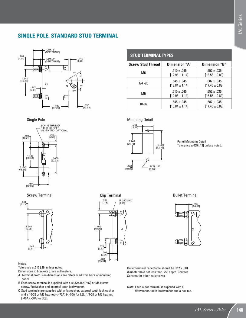
SINGLE POLE, STANDARD STUD TERMINAL
[19.05].750
[36.53]1.438
[63.24]2.490
[10.21].402 [5.59]
.220
[52.32]2.060
2X 6-32 THREAD.140 [3.56] DEEPM3 ISO THD. OPTIONAL
(SEE TABLE)
(SEE TABLE) [3.56].140
[3.61].142
[47.22]1.859
[17.53].690
ON
OFF
[7.14].281
[49.28]1.940
[7.13].281
[49.28]1.940
[3.61].142
Screw Terminal
[7.13].281
[49.28]1.940
[6.35]Ø .250 MAX.
[15.04].592
[9.96].392
[9.53].375
Single Pole
Clip Terminal
[24.57].967
Bullet Terminal
Notes: Tolerance ± .015 [.39] unless noted. Dimensions in brackets [ ] are millimeters.A Terminal protrusion dimensions are referenced from back of mounting
panel.B Each screw terminal is supplied with a 10-32x.312 [7.92] or M5 x 8mm
screw, flatwasher and external tooth lockwasher.C Stud terminals are supplied with a flatwasher, external tooth lockwasher
and a 10-32 or M5 hex nut (<=70A) (<=50A for LEL),1/4-20 or M6 hex nut (>70A)(>50A for LEL).
[19.18].755
[52.32]2.060[36.78]
1.448
[3.96]2X Ø .156
[10.98].432
Mounting Detail
Note: Each outer terminal is supplied with a flatwasher, tooth lockwasher and a hex nut.
Bullet terminal receptacle should be .312 ± .001 diameter hole not less than .250 depth. Contact Sensata for other bullet sizes.
Note: A Terminal protrusion dimensions are referenced from back of mounting panel.B Each screw terminal is supplied with a 10-32x.312 [7.92] or M5 x 8mm screw, flatwasher and external tooth lockwasher.C Stud terminals are supplied with a flatwasher, external tooth lockwasher and a 10-32 or M5 hex nut (<=70A), 1/4 -20 or M6 hex nut (>70A).
(SEE TABLE)
(SEE TABLE) [3.56].140
[3.61].142
[47.22]1.859
[17.53].690
ON
OFF
[7.14].281
[49.28]1.940
Two Pole
[5.59].220
MAX.
[36.53]1.438
[63.24]2.490
[10.21].402
[52.32]2.060
[38.48]1.515
4X 6-32 THREAD.140 [3.56] DEEPM3 ISO THD. OPTIONAL
MAX.[38.48]1.515
IELH11 IEL11
Note:Tolerance ± .015 [.38] unless noted. Dimensions in brackets [ ] are millimeters.
[19.05].750
[52.32]2.060
[38.86]1.530
[36.78]1.448
[10.97].432
[3.96]4X Ø .156
Two Pole*
[19.05].750
Two Pole*
M6
1/4 - 20
M5
10 - 32
Screw stud thread
.510
.545
.510
.545
Dim. “A”(± .045)
.652
.687
.652
.687
Dim. “B”(± .035)
Note:Each outer terminal is supplied with a flatwasher, tooth lockwasher and a hex nut. Panel Mounting Detail
Tolerance ±.005 [.13] unless noted.
Multi-pole units are combined in an assembly with the trip mechanisms internally coupled. A fault in any protected circuit opens all poles simultaneously. Applications include use in polyphase circuits, single-phase three-wire systems, or in two or more related but electrically isolated circuits. A mix of delays, ratings and configurations are offered. The auxiliary switch is offered with either gold or silver contacts and is available when a series construction pole is specified.
Two Pole Units
An assembly consisting of two single pole units, having their trip mechanisms internally coupled, is available with either a single toggle handle or with a handle per pole. Please see decision one of the part number decision tables. Individual poles may vary in ratings, delays and internal configurations. If the poles are of series construction, an auxiliary switch may be included in either or both poles, allowing you to mix SELV and hazardous voltages.
MULTI-POLE CIRCUIT PROTECTORS
IAL Series - Poles http://airpax.sensata.com149
[57.53]2.265
MAX.
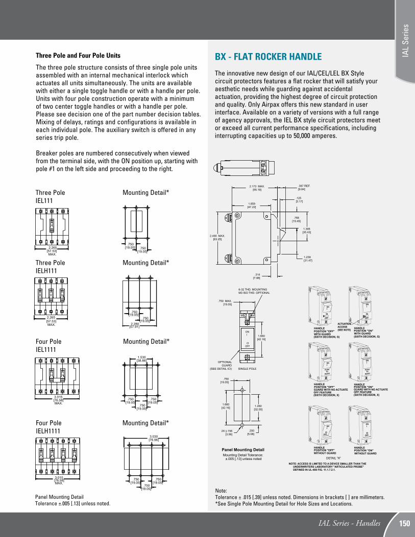
Three Pole and Four Pole Units
The three pole structure consists of three single pole units assembled with an internal mechanical interlock which actuates all units simultaneously. The units are available with either a single toggle handle or with a handle per pole. Units with four pole construction operate with a minimum of two center toggle handles or with a handle per pole. Please see decision one of the part number decision tables. Mixing of delays, ratings and configurations is available in each individual pole. The auxiliary switch is offered in any series trip pole.
Breaker poles are numbered consecutively when viewed from the terminal side, with the ON position up, starting with pole #1 on the left side and proceeding to the right.
Three PoleIEL111
MAX.[57.53]2.265
Mounting Detail*
[19.05].750
[19.05].750
[57.91]2.280
MAX.[76.58]3.015
Four PoleIEL1111
[19.05].750
[19.05].750
[19.05].750
[38.86]1.530
Mounting Detail*
[19.05].750
[19.05].750
Note:Tolerance ± .015 [.39] unless noted. Dimensions in brackets [ ] are millimeters.*See Single Pole Mounting Detail for Hole Sizes and Locations.
Three PoleIELH111
MAX.[76.58]3.015
[19.05].750
[19.05].750
[19.05].750
[76.96]3.030
Mounting Detail*Four PoleIELH1111
Mounting Detail*
BX - FLAT ROCKER HANDLE The innovative new design of our IAL/CEL/LEL BX Style circuit protectors features a flat rocker that will satisfy your aesthetic needs while guarding against accidental actuation, providing the highest degree of circuit protection and quality. Only Airpax offers this new standard in user interface. Available on a variety of versions with a full range of agency approvals, the IEL BX style circuit protectors meet or exceed all current performance specifications, including interrupting capacities up to 50,000 amperes.
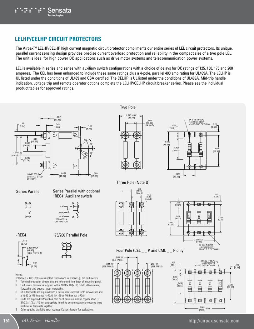
The Airpax™ LELHP/CELHP high current magnetic circuit protector compliments our entire series of LEL circuit protectors. Its unique, parallel current sensing design provides precise current overload protection and reliability in the compact size of a two pole LEL. The unit is ideal for high power DC applications such as drive motor systems and telecommunication power systems.
LEL is available in series and series with auxiliary switch configurations with a choice of delays for DC ratings of 125, 150, 175 and 200 amperes. The CEL has been enhanced to include these same ratings plus a 4-pole, parallel 400 amp rating for UL489A. The LELHP is UL listed under the conditions of UL489 and CSA certified. The CELHP is UL listed under the conditions of UL489A. Mid-trip handle indication, voltage trip and remote operator options complete the LELHP/CELHP circuit breaker series. Please see the individual product tables for approved ratings.
Series Parallel
ON
OFF
[17.53].690
[47.22]1.859
[49.28]1.940
[7.14].281
[3.56].140[13.84]
.545
[16.26].640
[26.59]1.047
[32.56]1.282
[17.45].687
1/4-20 STUD(M6 x 1.0 STUD OPTION)
[52.32]2.060
[5.59].220
[36.53]1.438
[10.21].402
[63.25]2.490
[19.05].750
2X 6-32 THREAD.140 [3.56] DEEPM3 ISO THD OPTIONAL
C
NO
NCBREAKER IN
OFF POSITION
Series Parallel with optional 1REC4 Auxiliary switch
Notes: Tolerance ± .015 [.39] unless noted. Dimensions in brackets [ ] are millimeters.A Terminal protrusion dimensions are referenced from back of mounting panel.B Each screw terminal is supplied with a 10-32x.312[7.92] or M5 x 8mm screw,
flatwasher and external tooth lockwasher.C Stud terminals are supplied with a flatwasher, external tooth lockwasher and
a 10-32 or M5 hex nut (<=70A), 1/4 -20 or M6 hex nut (>70A).D Units are supplied without bus bars must have a minimum copper strap (1
31/32 x 1/2 x 1/16 ) of appropriate length to accommodate connections tying each set of terminals together.
E Other spacing available upon request. Contact factory for assistance.
[6.60].260
[2.79].110
2.438 MAX[61.93](SEE NOTE 1)
-REC4
[38.48]1.515 MAX
[18.80].740
(Note E)
32
32
[17.53].690
[47.22]1.859
6X
6X
[49.28]1.940
[7.14].281
[3.56].140
[6.40].252
[36.53]1.438
[10.21].402
[63.25]2.490
[57.53]2.265 MAX.
6X
[14.10].555
[7.90].311
[10.77].424
[7.59].299
[18.80](Note E)
.740
[50.83]2.001
OFF
[3.61].142
[17.45].687
[13.84].545
OFF OFF
[32.77]1.290
[16.46].648
ON
OFF
[52.32]2.060
[5.59].220
6X 1/4-20 STUD
6X 6-32 THREAD.140 [3.56] DEEPM3 ISO THD OPTIONAL
1.055[26.79]
[18.80](Note E)
.740
Two Pole
Three Pole (Note D)
175/200 Parallel Pole
32
32
[17.53].690
[47.22]1.859
6X
6X
[49.28]1.940
[7.14].281
[3.56].140
[6.40].252
[36.53]1.438
[10.21].402
[63.25]2.490
[57.53]2.265 MAX.
6X
[14.10].555
[7.90].311
[10.77].424
[7.59].299
[18.80](Note E)
.740
[50.83]2.001
OFF
[3.61].142
[17.45].687
[13.84].545
OFF OFF
[32.77]1.290
[16.46].648
ON
OFF
[52.32]2.060
[5.59].220
6X 1/4-20 STUD
6X 6-32 THREAD.140 [3.56] DEEPM3 ISO THD OPTIONAL
1.055[26.79]
[18.80](Note E)
.740
LELHP/CELHP CIRCUIT PROTECTORS
Four Pole (CEL _ _ P and CML _ _ P only)
8X 6-32 THREAD.140 [3.56] DEEP
M3 ISO THD OPTIONAL
OFF FFOFFOFFO
3.005[76.33]
.40210.21
1.43836.53
2.49063.25
.2205.59
2.06052.32
(SEE TABLE)DIM. "H"
(SEE TABLE)DIM. "H"
(SEE TABLE)DIM. "H"
MAX
IAL Series - Handles http://airpax.sensata.com151
The lALN/IULN family is a sealed toggle version of the IAL/IUL family. The silicone rubber seal around the handle assures panel seal integrity and makes this style a natural for harsh environments.
This sealed toggle family is available in one to three pole models with ratings of .050 to 100 amperes.
[34.92]1.375
[16.66].656
[63.25]2.490
[19.05].750
KEYWAY.060 [1.52]-.065 [1.65] WIDE.030 [.76]-.035 [.89] DEEP
[38.48]1.515
(OPTIONAL, HANDLEMAY BE IN POLE 2INSTEAD OF POLE 1)
MAX.[57.53]2.265
MAX.
Three PoleSingle Pole Two Pole
(Optional handle may be in pole 2 instead of pole 1.)
[13.08]Ø.515
[3.96]Ø.156
[16.66].656
[19.05].750
MAX.[19.05]
.750[19.05]
.750
MAX. MAX.
[51.82]2.040
[3.30].130
ON
OFF
6-32 MTG. SCREW
1/2-32 HEX NUT
LOCKWASHER
[19.05].750
[15.88].625[3.61]
.142
FOR HIGH SHOCKMTG.
Optional handle
Notes:A Terminal protrusion dimensions are referenced from back of mounting panel.B Each screw terminal is supplied with a 10-32x.312[7.92] or M5 x 8mm screw, flatwasher and external tooth lockwasher.C Stud terminals are supplied with a flatwasher, external tooth lockwasher and a 10-32 or M5 hex nut (<=70A), 1/4 -20 or M6 hex nut (>70A).
*See Single Pole Mounting Detail for Hole Sizes and Locations.
IALN/IULN PANEL SEAL CIRCUIT PROTECTORS
IAL Series - Handles
IAL
Serie
s
152
Two Pole Three Pole Four Pole
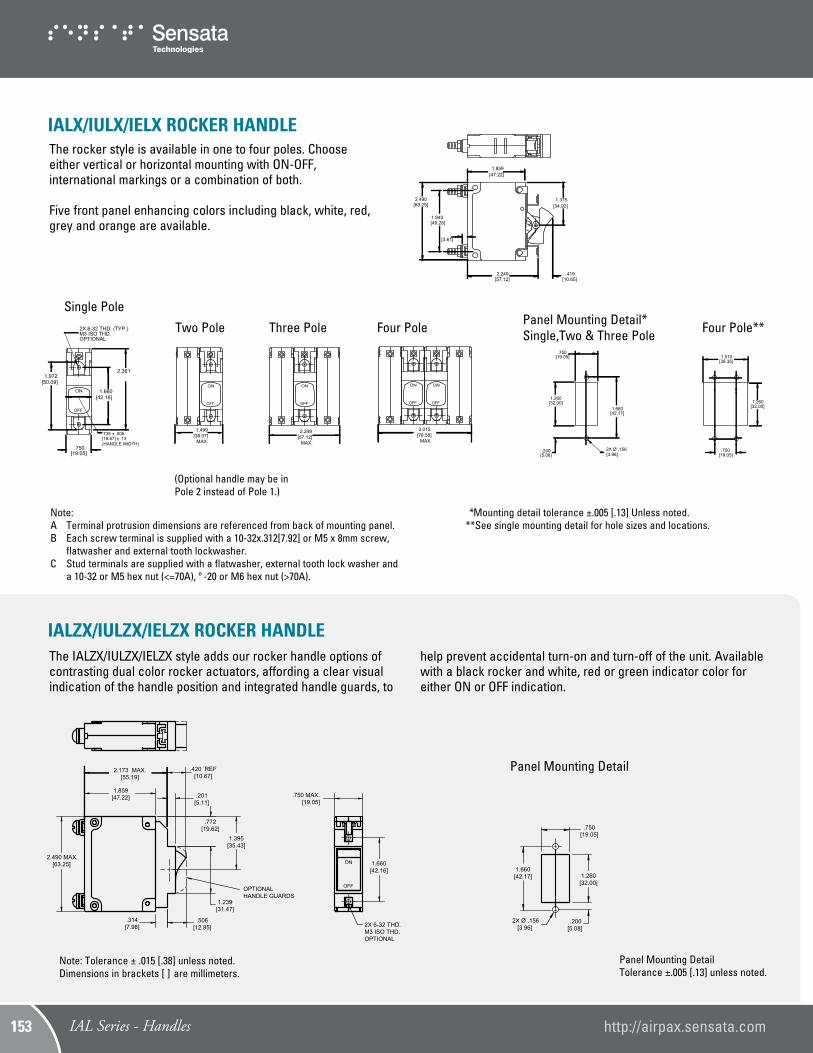
The rocker style is available in one to four poles. Choose either vertical or horizontal mounting with ON-OFF, international markings or a combination of both.
Five front panel enhancing colors including black, white, red, grey and orange are available.
[47.22]1.859
[57.12]2.249
[10.65].419
[34.92]1.375
[63.25]2.490
[49.28]1.940
[3.61]
Note: Tolerance ± .015 [.38] unless noted. Dimensions in brackets [ ] are millimeters.
OFF
ON
[19.05].750
[42.16]1.660
[50.09]1.972
[18.67]
2.361
2X 6-32 THD. (TYP.)M3 ISO THD.OPTIONAL
.735
(HANDLE WIDTH)
OFF
ON
MAX.[38.07]1.499
OFF
ON
MAX.[57.12]2.249
OFF
ON
OFF
ON
MAX.[76.58]3.015
[19.05].750
[42.17]1.660
[3.96]2X Ø .156
1.260[32.00]
[5.08].200
[38.35]1.510
[19.05].750
[32.00]1.260
Note: A Terminal protrusion dimensions are referenced from back of mounting panel.B Each screw terminal is supplied with a 10-32x.312[7.92] or M5 x 8mm screw,
flatwasher and external tooth lockwasher.C Stud terminals are supplied with a flatwasher, external tooth lock washer and
a 10-32 or M5 hex nut (<=70A), º -20 or M6 hex nut (>70A).
Single PolePanel Mounting Detail* Single,Two & Three Pole Four Pole**
*Mounting detail tolerance ±.005 [.13] Unless noted.**See single mounting detail for hole sizes and locations.
(Optional handle may be in Pole 2 instead of Pole 1.)
The IALZX/IULZX/IELZX style adds our rocker handle options of contrasting dual color rocker actuators, affording a clear visual indication of the handle position and integrated handle guards, to
1.239[31.47]
.420 REF[10.67]
.750 MAX.[19.05]
2X 6-32 THD.M3 ISO THD.OPTIONAL
ON
.506[12.85]
OPTIONALHANDLE GUARDS
1.660[42.16]
OFF
.772[19.62]
Panel Mounting DetailsMounting Detail Tolerance:
±.005 [.13] Unless Noted.
1.859[47.22]
2.173 MAX.[55.19]
.314[7.98]
.201[5.11]
1.395[35.43]
2.490 MAX.[63.25]
1.660[42.17]
.750[19.05]
1.260[32.00]
2X Ø .156[3.96]
.200[5.08]
Panel Mounting Detail
help prevent accidental turn-on and turn-off of the unit. Available with a black rocker and white, red or green indicator color for either ON or OFF indication.
Series TripThe most popular configuration for magnetic protectors is the series trip where the sensing coil and contacts are in series with the load being protected. The handle position conveniently indicates circuit status. In addition to providing conventional overcurrent protection, it’s simultaneously used as an on-off switch.
Shunt TripThe shunt trip is designed for controlling two separate loads with one assembly. The control is established by providing overload protection for the critical load. When the current through this load becomes excessive and reaches the trip point, the protector will open and remove power from both loads simultaneously. The total current rating of both loads must not exceed the maximum contact rating.
Dual CoilBy combining two electrically independent coils on a common magnetic circuit, it is possible to provide contact opening when either an over-current or trip voltage is applied to the respective coils. One coil will be a current trip coil with standard specifications. The second, or dual coil, can be used to provide a control function permitting contact opening from a remote interlock or other transducer functions. Standard coils are 6, 12, 24, 48, 120 and 240 volts. Tripping is instantaneous and must be removed (usually self-interrupting) after trip.
Auxiliary Switch (Applies to Series Trip Only)This is furnished as an integral part of a series pole in single or multi-pole assemblies. Isolated electrically from the protector’s circuit, the switch works in unison with the power contacts and provides indication at a remote location of the protector’s on-off status. Auxiliary switch contacts actuate simultaneously with the main breaker contacts, and will open regardless of whether the breaker contacts are opened manually or electrically. For auxiliary switch ratings below 6Vac or 5Vdc, an auxiliary switch with gold contacts, designated as REG is available. Gold contacts are not recommended for load current above 100 milliamps.
SWITCH ONLYSERIES1.940
[49.28]
.281[7.13]
Dimension B(See Table)
Dimension A(See Table)
1.290[32.77]
.648[16.46]
1.055[26.80]
NCNO
C
BREAKER IN OFF POSITION
1.26[32.00]
.278[7.05]
1.940[49.28]
2.640 MAX.[67.06](SEE NOTE A)
.795[20.19]
.660 ±.045[16.76] ±1.14]
1.266[32.16]
.971[24.66]
.676[17.17]
Dimension B(See Table)
-IREC5
.250[6.35]
.187[4.75]
-IREC4, -IREG4
.260[6.60]
.110[2.79]
2.454 MAX.[64.52](SEE NOTE A)
2.438 MAX.[64.52](SEE NOTE A)
-IREC5
.250[6.35]
.187[4.75]
-IREC4, -IREG4
.260[6.60]
.110[2.79]
2.454 MAX.[64.52](SEE NOTE A)
2.438 MAX.[64.52](SEE NOTE A)
DUAL COILSHUNT
Spacing for VDE Switch
Series with Auxiliary Switch
[17.17].676
[24.66].971
[32.16]1.266
Note: Each outer terminal is supplied with a flatwasher, tooth lockwasher and a hex nut.
Note:A Terminal protrusion dimensions are referenced from back of mounting
panel.B Each screw terminal is supplied with a 10-32x.312[7.92] or M5 x 8mm
screw, flatwasher and external tooth lockwasher.C Stud terminals are supplied with a flatwasher, external tooth lock
washer and a 10-32 or M5 hex nut (<=70A), 1/4-20 or M6 hex nut (>70A).
Series and Switch Only
Shunt and Dual Coil
CONFIGURATIONS
STUD TERMINAL TYPES
Screw Stud Thread Dimension “A” Dimension “B”
M6 .510 ± .045 [12.95 ± 1.14]
.652 ± .035 [16.56 ± 0.89]
1/4 -20 .545 ± .045 [13.84 ± 1.14]
.687 ± .035 [17.45 ± 0.89]
M5 .510 ± .045 [12.95 ± 1.14]
.652 ± .035 [16.56 ± 0.89]
10-32 .545 ± .045 [13.84 ± 1.14]
.687 ± .035 [17.45 ± 0.89]
IAL Series - Configurations
IAL
Serie
s
154
Relay TripThis permits the overload sensing coil to be placed in a circuit which is electrically isolated from the trip contacts. The coil may be actuated by sensors monitoring pressure, flow, temperature, speed, etc. Other typical applications include crowbar, interlock and emergency/rapid shutdown circuitry. Trip may be accomplished by voltage or current, which must be removed after trip.
Voltage TripSometimes called “dump circuits” or “panic trip circuits,” these units make it possible to open main power contacts with lower power inputs from one or more sources. This configuration is becoming increasingly more important for sensitive circuitry and denser packaging in automation systems. Available in series, shunt or relay configurations.
[18.34].722
[33.78]1.330
[7.14].281
[16.76±1.14].660±.045
[49.28]1.940
(SEE NOTE A)[67.06]
2.640 MAX
[20.19].795
RELAY DUAL COIL
Relay and Dual Coil
Notes: Tolerance ± .015 [.39] unless noted. Dimensions in brackets [ ] are millimeters.A Terminal protrusion dimensions are referenced from back of mounting panel.B Each screw terminal is supplied with a 10-32x.312[7.92] or M5 x 8mm screw,
flatwasher and external tooth lockwasher.C Stud terminals are supplied with a flatwasher, external tooth lockwasher and
a 10-32 or M5 hex nut (<=70A), 1/4 -20 or M6 hex nut (>70A).
RELAY DUAL COIL
Barriers
[69.60]2.740
[17.02].670
[27.89]1.098
[65.02]2.560
[29.13]1.147
[18.31].721
[65.02]2.560
[29.13]1.147
[18.31].721
[.84].033
[78.74]3.100
[35.00]1.378
[24.18].952 [7.69]
.303
[3.11].122
[.84].033
NOTE:THIS BARRIER CAN BE FLIPPEDTO COVER EITHER POLE. PLEASE CONTACT FACTORY FOR SPECIFIC PART NUMBER
FIG.4FIG.3
FIG.2FIG.1
CONFIGURATIONS (CONT.)
BARRIER OPTIONS
Rating Option Standard Barrier
Optional Barrier
IEL240/415 VAC
Fig. 1 Fig. 2, 3 & 4415 VAC (VDE)
277/480 VAC
1/4-20, M6 studs for AC
120/240 VAC multi-poleFig. 2 Fig. 3 & 4
125VDC
LEL
All multi-pole 50/60 Hz Fig. 2 Fig. 3 & 4
All multi-pole 80 VDC, if opposite polarity Fig. 2 Fig. 3 & 4
125VDC Fig. 2 Fig. 3 & 4
Note: Optional barrier available with factory assigned part number. Contact factory for assistance.
IAL Series - Configurations http://airpax.sensata.com155
Mid-Trip IndicationCircuit protection, rapid fault location and alarm capability are blended together in the Airpax mid-trip indication option. This option is designed for automatic handle movement to a middle position upon electrical overload, allowing for easier detection of the fault circuitand minimizing downtime due to the overload condition. In the optional auxiliary switch configuration, the switch allows an alarm or signal to be forwarded when the breaker trips and the handle moves to the middle position. The alarm can be disengaged by the manual actuation of the handle to the OFF position. Once the fault has been corrected, the circuit breaker can be reset to the ON position. The mid-trip option is available in one, two or three pole toggle handle packages and in either standard panel screw or snap-in mounting. Please see specification tables of specific product for available ratings.
Snap-In MountingThe snap-in mounting adapter allows for simplified mounting of most IEL/LEL toggle handle products. Prior to shipment, the adapter is attached to the circuit breaker during our final product assembly, allowing you to securely snap the unit into a rectangular panel cut-out. This eliminates the need for panel mounting hardware and associated assembly costs. Available for units up to three poles, with or without an option handle guard.
C
NONC
C
NONC
BREAKER IN ON OR MANUALLY TURNED OFF POSITION
BREAKER IN MID-TRIP POSITION (ELECTRICALLY TRIPPED)
ON
POSITION
OFFPOSITION
MID-TRIPPOSITION
(SEE TABLE)
[74.63 ±.18]2.938±.007
DIM.“A”
[52.35]2.061
[25.27].995
[81.79]3.220
[44.45]1.750
[63.37]2.495
[17.45].687
[39.62]1.560
Mid-Trip Handle Positions
Panel Mounting Detail
Note: Tolerance ± .015 [.39] unless noted. Dimensions in brackets [ ] are millimeters.
Notes: DCR and impedance based on 100% rated current applied and stablized a minimum of one hour.No 53 delay on 125 amp single pole or 400 amp four pole devices Tolerance: .02 amperes to 2.5 amperes, ± 20%; 2.6 amperes to 20 amperes, ± 25%; 21 amperes to 50 amperes, ± 50%. Consult factory for special values and for coil impedance of delays not shown ** Paralleled poles only, 400 amps only available on CELHP
IAL Series - Operating Characteristics http://airpax.sensata.com157
http://airpax.sensata.com/ IAL/CEL/LEL Series - Operating Characteristics 150
PERCENTAGE OF RATED CURRENT VS TRIP TIME IN SECONDS AT +25°C
Delay 100% 125%* 150% 200% 400% 600% 800% 1000%
41* No Trip May trip .5 to 8 .15 to 1.9 .02 to .4 .006 to .25 .004 to .1 .004 to .05
42* No Trip May trip 5 to 70 2.2 to 25 .40 to 5 .012 to 2 .006 to .2 .006 to .15
43* No Trip May trip 35 to 350 12 to 120 1.5 to 20 .012 to 2.2 .01 to .22 .01 to .1
49* No Trip May trip .100 max. .050 max. .020 max. .020 max. .020 max. .020 max.
51 No Trip .5 to 6.5 .3 to 3 .1 to 1.2 .031 to .5 .011 to .25 .004 to .1 .004 to .08
52 No Trip 2 to 60 1.8 to 30 1 to 10 .15 to 2 .04 to 1 .008 to .5 .006 to .1
53** No Trip 80 to 700 40 to 400 15 to 150 2 to 20 .23 to 9 .015 to .55 .012 to .2
61 No Trip .7 to 12 .35 to 7 .130 to 3 .030 to 1 .015 to .3 .01 to .15 .008 to .1
62 No Trip 10 to 120 6 to 60 2 to 20 .2 to 3 .02 to 2 .015 to .8 .01 to .25
63 No Trip 50 to 700 30 to 400 10 to 150 1.5 to 20 .4 to 10 .013 to .85 .013 to .5
69 No Trip .120 max .100 max. .050 max. .022 max. .017 max. .017 max. .017 max
71 No Trip .44 to 10 .3 to 7 .100 to 3 .030 to 1 .012 to .3 .004 to .15 .004 to .1
72 No Trip 1.8 to 100 1.7 to 60 1 to 20 .15 to 3 .015 to 2 .008 to .79 .006 to .28
73 No Trip 50 to 600 30 to 400 10 to 150 1.8 to 20 .015 to 10 .015 to .88 .011 to .5
79 No Trip .120 max .100 max. .050 max. .023 max. .016 max. .015 max. .015 max
Notes: All trip curves and trip currents are specified with the protector mounted in the normal vertical position at ambient temperature of +25° C. Protectors do not carry current prior to application of overload. A: Ratings above 30 amps may deviate from the above limits by approximately 10% (130% for delay 49). * No 53 delay on 125 amp single pole or 400 amp four pole devices * 135% for delay 71, 72, 73 & 79
IAL Series - Operating Characteristics
IAL
Serie
s
158
800700600500400300200150125
1000
TIM
E IN
SE
CO
ND
S
10
1
.1
1000
100
.01
10000
.001
PERCENT OF RATED CURRENT
1000900
DELAY 61
MA
Y T
RIP
800700600500400300200150125
1000
TIM
E IN
SE
CO
ND
S
10
1
.1
1000
100
.01
10000
.001
PERCENT OF RATED CURRENT
1000900
DELAY 62DELAY 62DELAY 62M
AY
TR
IP
800700600500400300200150125
1000
TIM
E I
N S
EC
ON
DS
10
1
.1
1000
100
.01
10000
.001
PERCENT OF RATED CURRENT
1000900
DELAY 63
MA
Y T
RIP
800700600500400300200150125
1000
TIM
E IN
SE
CO
ND
S
10
1
.1
1000
100
.01
10000
.001
PERCENT OF RATED CURRENT
1000900
DELAY 69
MA
Y T
RIP
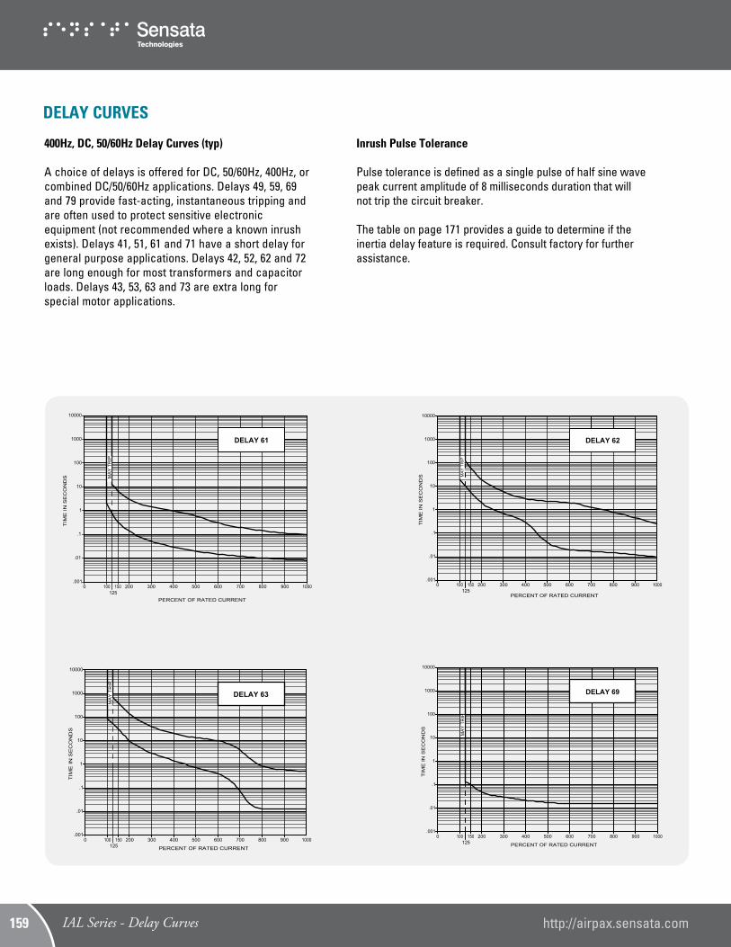
400Hz, DC, 50/60Hz Delay Curves (typ)
A choice of delays is offered for DC, 50/60Hz, 400Hz, or combined DC/50/60Hz applications. Delays 49, 59, 69 and 79 provide fast-acting, instantaneous tripping and are often used to protect sensitive electronic equipment (not recommended where a known inrush exists). Delays 41, 51, 61 and 71 have a short delay for general purpose applications. Delays 42, 52, 62 and 72 are long enough for most transformers and capacitor loads. Delays 43, 53, 63 and 73 are extra long for special motor applications.
Inrush Pulse Tolerance
Pulse tolerance is defined as a single pulse of half sine wave peak current amplitude of 8 milliseconds duration that will not trip the circuit breaker. The table on page 171 provides a guide to determine if the inertia delay feature is required. Consult factory for further assistance.
800700600500400300200150125
1000
TIM
E IN
SE
CO
ND
S
10
1
.1
1000
100
.01
10000
.001
PERCENT OF RATED CURRENT
1000900
DELAY 61
MA
Y T
RIP
800700600500400300200150125
1000
TIM
E IN
SE
CO
ND
S
10
1
.1
1000
100
.01
10000
.001
PERCENT OF RATED CURRENT
1000900
DELAY 62DELAY 62DELAY 62
MA
Y T
RIP
800700600500400300200150125
1000
TIM
E I
N S
EC
ON
DS
10
1
.1
1000
100
.01
10000
.001
PERCENT OF RATED CURRENT
1000900
DELAY 63
MA
Y T
RIP
800700600500400300200150125
1000
TIM
E IN
SE
CO
ND
S
10
1
.1
1000
100
.01
10000
.001
PERCENT OF RATED CURRENT
1000900
DELAY 69
MA
Y T
RIP
DELAY CURVES
http://airpax.sensata.com/IAL/CEL/LEL Series - Operating Characteristics149 IAL Series - Delay Curves http://airpax.sensata.com159
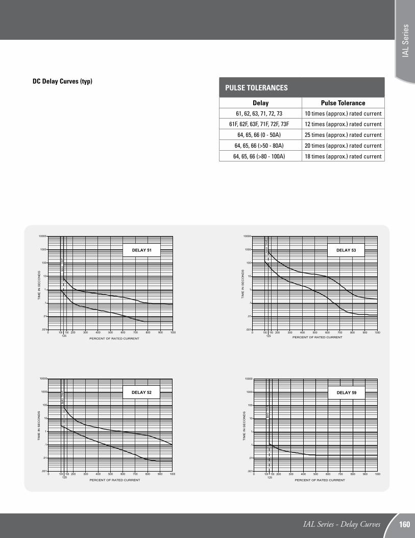
DC Delay Curves (typ)
800700600500400300200150125
1000
10
1
.1
1000
100
.01
10000
.001
PERCENT OF RATED CURRENT
1000900
DELAY 51
MA
Y T
RIP
800700600500400300200150125
1000
TIM
E IN
SE
CO
ND
S
10
1
.1
1000
100
.01
10000
.001
PERCENT OF RATED CURRENT
1000900
DELAY 52
MA
Y T
RIP
800700600500400300200150125
1000
TIM
E IN
SE
CO
ND
S
10
1
.1
1000
100
.01
10000
.001
PERCENT OF RATED CURRENT
1000900
DELAY 53MA
Y T
RIP
800700600500400300200150125
1000
TIM
E I
N S
EC
ON
DS
10
1
.1
1000
100
.01
10000
.001
PERCENT OF RATED CURRENT
1000900
DELAY 59
MA
Y T
RIP
TIM
E IN
SE
CO
ND
S
PULSE TOLERANCES
Delay Pulse Tolerance61, 62, 63, 71, 72, 73 10 times (approx.) rated current
61F, 62F, 63F, 71F, 72F, 73F 12 times (approx.) rated current
64, 65, 66 (0 - 50A) 25 times (approx.) rated current
64, 65, 66 (>50 - 80A) 20 times (approx.) rated current
64, 65, 66 (>80 - 100A) 18 times (approx.) rated current
http://airpax.sensata.com/ IAL/CEL/LEL Series - Operating Characteristics 150IAL Series - Delay Curves
IAL
Serie
s
160
400Hz Delay Curves (typ)*Available only in IAL/IUL/IEL; not available in LEL.
800700600500400300200150125
1000
10
1
.1
1000
100
.01
10000
.001
PERCENT OF RATED CURRENT
1000900
DELAY 41
MA
Y T
RIP
800700600500400300200150125
1000
TIM
E IN
SE
CO
ND
S
10
1
.1
1000
100
.01
10000
.001
PERCENT OF RATED CURRENT
1000900
DELAY 42
MAY
TR
IP
800700600500400300200150125
1000
TIM
E IN
SE
CO
ND
S
10
1
.1
1000
100
.01
10000
.001
PERCENT OF RATED CURRENT
1000900
DELAY 43
MA
Y T
RIP
800700600500400300200150130
1000
TIM
E IN
SE
CO
ND
S
10
1
.1
1000
100
.01
10000
.001
PERCENT OF RATED CURRENT
1000900
DELAY 49
MAY
TR
IP
TIM
E IN
SE
CO
ND
S
http://airpax.sensata.com/IAL/CEL/LEL Series - Operating Characteristics149 IAL Series - Delay Curves http://airpax.sensata.com161
DELAY 79
800700600500400300200150135
1000
TIM
E IN
SE
CO
ND
S
10
1
.1
1000
100
.01
10000
.001
PERCENT OF RATED CURRENT
1000900
MAY
TR
IP
800700600500400300200150135
1000
TIM
E IN
SE
CO
ND
S
10
1
.1
1000
100
.01
10000
.001
PERCENT OF RATED CURRENT
1000900
DELAY 71
800700600500400300200150135
1000
TIM
E IN
SE
CO
ND
S
10
1
.1
1000
100
.01
10000
.001
PERCENT OF RATED CURRENT
1000900
DELAY 73
800700600500400300200150135
1000
TIM
E IN
SE
CO
ND
S
10
1
.1
1000
100
.01
10000
.001
PERCENT OF RATED CURRENT
1000900
MAY
TR
IP
DELAY 72
MA
Y T
RIP
MAY
TR
IP
DC/50/60Hz Dual-frequency Delay Curves (typ)
http://airpax.sensata.com/ IAL/CEL/LEL Series - Operating Characteristics 150IAL Series - Delay Curves
IAL
Serie
s
162
IAL/IUL/IEL/IDL/LEL SPECIFICATIONSTrip FreeWill trip open on overload even when forcibly held in the ON position. This prevents the operator from damaging the circuit by holding the breaker on.
Trip IndicationThe operating handle moves positively to the OFF or mid-trip position on electrical overload.
Ambient OperationIAL/IUL/IEL protectors operate in temperatures between –40°C to +85°C.
Insulation ResistanceNot less than 100 megohms at 500 volts DC.
Dielectric StrengthIAL/IUL/IEL protectors withstand 3750Vac (1250Vac for LEL), 60Hz for 60 seconds between all electrically isolated terminals except auxiliary switch terminals shall withstand 600Vac, 60Hz for REG and REC types. Four terminal dual coil and relay con-struction (not offered in the LEL) will withstand 1500Vac.
EnduranceOperating as a switch, the operating life exceeds 10,000 oper-ations, 6000 at rated load, 4000 without load, at a rate of 6 per minute.
Electrical Characteristics.050-100 amperes 80Vdc, 240Vac Max., 240/415Vac at 50 amperes Max., 50/60Hz and 400Hz. Consult factory for specific product ratings. Units rated for 240/415Vac and above 50 amperes are not suitable for across-the-line motor starting.
PolesOne through six poles available. ConstructionSeries, shunt, relay dual coil and series with auxiliary switch available in various delays and combinations.
Auxiliary SwitchWhen supplied shall be S.P.D.T. configuration. Non VDE approved switches have a maximum UL rating of 10.0 amperes, 250 volts, 60Hz; 3.0 amperes, 50 volts DC (REC type) or 0.1 amperes, 125 volts, 60Hz (REG type).
VDE approved switches have a maximum UL rating of 10.0 amperes, 250 volts, 60Hz (REC type); or 0.1 amperes, 125 volts, 60Hz (REG; type). The maximum VDE ratings are 1.0 amperes, 125 volts, 60Hz (REC type); 0.1 amperes, 125 volts, 60Hz (REG type).
Salt Spray (Corrosion)Meet the requirements of MIL-PRF-55629 when tested in accordance with Method 101 of MIL-STD-202.
Moisture ResistanceMeet all the requirements of MIL-PRF-55629 when tested in accordance with Method 106 of MIL-STD-202.
ShockCircuit protectors shall not trip when tested per MIL-STD-202, Method 213, Test Condition I with 100% rated current applied to delayed units and 80% rated current to instantaneous units.
VibrationCircuit protectors shall not trip when vibrated per MIL-STD-202, Method 204, Test Condition A with 100% rated current applied to delayed units and 80% rated current to instantaneous units.
UL-1500 (Marine Ignition Protected)The IDL/IDLH is approved for Marine Ignition Protection (series configuration only), covering ignition protected circuit break-ers. This specification requires devices to be used in accordance with the requirementsof U.S. Coast Guard and Fire Protection Standard for Pleasure and Commercial Motor Craft, ANSI/MFPA #302.
APPROXIMATE WEIGHT PER POLE
Ounces Grams
3.1 90
RECOMMENDED TORQUE SPECIFICATIONS
Component Torque (in-lbs)
6-32 Mounting Inserts 6 to 8
M3 Mounting Screws 4 to 5
10-32 Screw Terminals 14 to 15
M5 Terminal Screws 14 to 15
10-32 Stud Terminals 13 to 14
M5 Stud Terminals 13 to 14
1/4 - 20 Stud Terminals 40 to 45
M6 Stud Terminals 40 to 45
1/2 - 32 Mounting Bushing 30 to 35
Where applicable, mechanical support must be provide to the terminals when applying torque
http://airpax.sensata.com/IAL/CEL/LEL Series - Operating Characteristics149 IAL Series - Specifications http://airpax.sensata.com163
65 DC - 1 .05-50 - 7500 -65 DC - 2** 101-150 - 50000 -80 DC - 1 .05-100 - 50000 -80 DC - 2** 101-200 - 10000 -80 DC - 3** 201-250 - 10000 -125 DC - 1 .05-70 - 5000 -80 DC - 1 15.1-125 - 10000 -
General notes:• All supplementary protectors are of the overcurrent (OC) type
• The family of protectors has been evaluated for end use application for use groups (UG) A, B, C and D
• The terminals (FW) are suitable for factory wiring only (0)
• The maximum voltage ratings for which the protectors have been tested are shown in the chart
• The current is the amperage range that the protectors have been tested
• The tripping current (TC) for all of the protectors is either either “1” (in the range of 125% to 135% of ampere rating) or “2” (more than 135% of ampere rating)
• The overload rating (OL) – designates whether the protector has been tested for general use or motor starting applications.
0 – tested at 1.5 times amp rating for general use
1 – tested at 6 times AC rating or 10 times DC rating for motor starting
• The short circuit current rating (SC) – The short circuit rating in amperes following a letter and number designating the test conditions and any calibration following the short circuit test is defined below:
C – Indicates short circuit test was conducted with series overcurrent protection
U – Indicates short circuit test was conducted without series overcurrent protection
1 – Indicates a recalibration was not conducted as part of the short circuit testing
2 – Indicates a recalibration was performed as part of the short circuit testing
3 – Indicates recalibration was performed along with the dielectric and voltage withstand for “Suitable for Further Use” rating
Notes:** Paralleled poles; + 2 poles in series; ++ 3 poles in series; (1) With 125 A max. series fuse; (2) Series combination with 209 or 229 series (100 A max.); (3) With 100 A max. series fuse; (4) With blocked vent construction (5) Non-standard construction. “Fit for further use” approval
http://airpax.sensata.com/ IAL/CEL/LEL Series - Operating Characteristics 150IAL Series - Specifications
IAL
Serie
s
164
IAL/IUL/IEL DECISION TABLES The ordering code for IAL/IUL/IEL/LEL circuit protectors may be determined by following the decision steps in the appropriate part number decision table subsequent to this page. The coding given permits a self-assigning part number but with certain limitations. Special applications may require a factory assigned part number. Typical examples are units with mixed ratings, combinations of styles, or constructions not listed in the third decision table, etc. With these, it is suggested that order entry be by description and/or drawings, and a part number will be established. Additionally, it is standard policy to establish a factory-assigned part number whenever a descriptive drawing exists to provide cross reference, traceability and manufacturing control. When specifying a circuit breaker for AC motor start or high inrush applications, the peak amplitude and surge duration should be specified for factory assistance in rating selection. For example the code shown is the code for a single pole breaker with a series construction and auxiliary switch, designed for operation in a 50/60Hz circuit. It has a short time delay, rating of 20 amperes and a marked black handle, and is VDE approved. To determine the ordering number for your particular IAL/IUL/IEL unit, simply follow the steps shown. You may use this number to place an order or as a reference for further questions you may have.
Notes:IEL, IELH and IELX circuit protectors are designed to meet 8mm creepage clearance requirements for installation Category 111, Pollution Degree 3, Case A as measured in IEC 664. Intended for use in equipment to comply with IEC 950, 601 and VDE 0804 & 0805.
Second Decision
Single pole
Two pole
Three pole
Four pole*
1
11
111
1111
2
Poles
*Not available in toggle seal handle type.Consult factory for 5 and 6 pole IEL part number.
Internal Con�guration
Third Decision3
* Only one auxiliary switch is normally supplied on two or three pole units. Switch is located in the right-hand pole (viewed from terminal end) unless otherwise speci�ed.
1 2 3 4
IEL 1 - 1REC4- 61- 20.0 - 01 - V
5 7
Example:
Black
Yellow
Red
Blue
Green
Orange
White
-00
-10
-20
-30
-40
-60
-90
-01 (STD)
-11
-21
-31
-41
-61
-91
Seventh Decision7
Handle Color and Marking Selection
IAL, IUL, IEL, IALH,IULH, IELH - Toggle Handle
Marked* ON-OFF Color Unmarked I-O
Fifth Decision5
Rated Current
Use three numbers to print requiredcurrent value between .100 ampsminimum and 100 amps maximum.
For example, use:.100 or 2.00 or 10.0
The VDE (lth) will be 95% of theUL/CSA rated current.
Fourth Decision4
Frequency & Delay
Switch only
400Hz short delay
400Hz long delay
400Hz motor start
400Hz 150% instant trip
DC short delay
DC long delay
DC motor start
DC 125% instant trip
50/60Hz short delay
50/60Hz long delay
50/60Hz motor start
50/60Hz 125% instant trip
DC/60Hz short delay
DC/60Hz long delay
DC/60Hz motor start
DC/60 Hz 135% instant tripFor addition of inertial delay, add an ìFî to any delay numeral.
SW
-41
-42
-43
-49
-51
-52
-53
-59
-61
-62
-63
-69
-71
-72
-73
-79
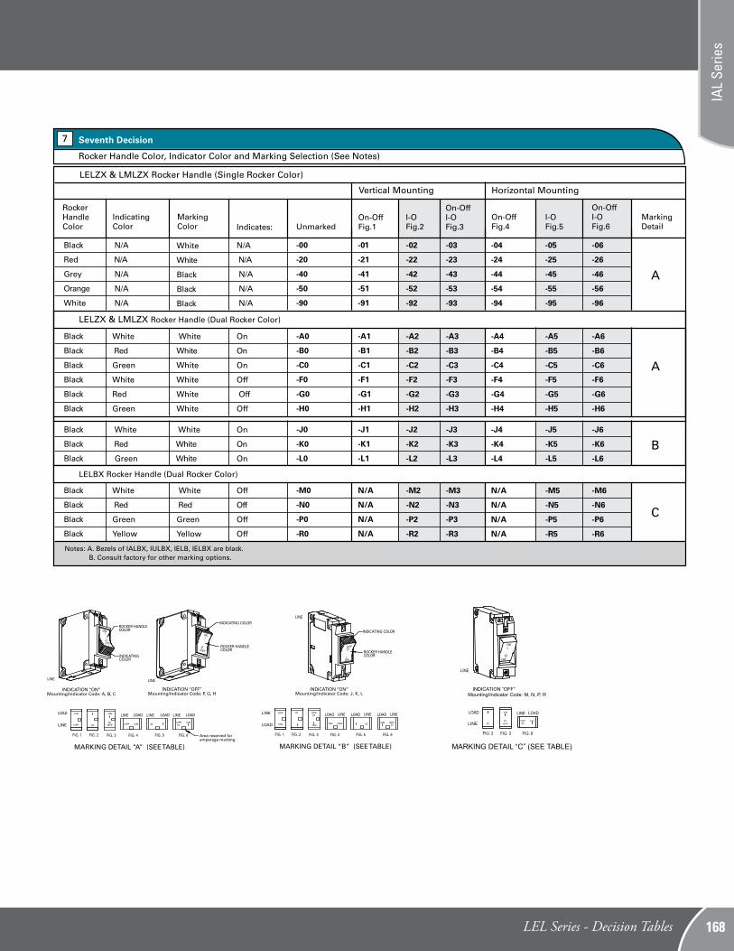
Notes: A. Bezels of IALBX, IULBX, IELB, IELBX are black. B. Consult factory for other marking options.
Note: CCC Approval is pending.
Black
Red
Grey
Orange
White
-00
-20
-40
-50
-90
-01
-21
-41
-51
-91
-02
-22
-42
-52
-92
-03
-23
-43
-53
-93
-04
-24
-44
-54
-94
-05
-25
-45
-55
-95
-06
-26
-46
-56
-96
I-O Fig.2Unmarked
MarkingDetail
Seventh Decision7
Rocker Handle Color, Indicator Color and Marking Selection (See Notes)
Notes: 1. One or more descriptions may be used as required.2. When this is not used, table one may be substituted and U.S. thread and two lockwashers will be supplied. Unit will be rated at 250V (50/60Hz only.)3. VDE approved at 250Vac4. VDE approved at 415Vac
-A
-B
-C
-D
-E
-G
-K
-L
-M
-P
-U
-W -X
-1
-2
Standard hardware. No designation required.
Metric thread mounting inserts and terminals
Barrier
277V (50/60Hz only) (See note 3)
240/415V (50/60Hz only)
277V/480V (50/60Hz only) (See note 4)
Handle guard, (available in ZX, BX and snap-in versions only)
1/4 - 20 stud (M6 stud when -A option is selected)(<=70A requires -K, if >70A do not use -K)
Handle lock
Handle in opposite pole
Snap-in face plate adapter
120/240V 50/60Hz
Wire clamp supplied (VDE approved up toand including 16.0 amps)
Handle guard with no actuation feature (BX rocker only)
Silver 5/16" (.312") bullet
Gold 5/16" (.312") bullet
Optional
The shaded areas denote VDE and CCC(if applicable) Approval options. This approvalrequires the addition of a V at the end of thepart number. The V will be added to any partnumber formed entirely from shaded decisions.If non-shaded areas are selected, the unit will notbe VDE or CCC Approved, but other approvalsstill apply.
V = VDE and CCC Approved
Description
Note: CCC Approval is pending.
-0
-1
-1REC4
-1REC5
-1REG4
-1RS4
-1RLS4
-1RS5
-3
-4
Switch only (50, 70 or 100 amp switch)
Series
Series with auxiliary switch*.110 quick connect
Series with auxiliary switch*.187 quick connect
Series with auxiliary switch.110 quick connect
Series with alarm switch,electrical trip, .110 quick connect terminals
Series with alarm switch,electrical trip, .110 quick connect terminals (mid-trip only)
Series with alarm switch,electrical trip, .187 quick connect terminals
Shunt
Relay (not available in IEL/IELX)
This approval requires the addition of a C at the endof the part number. The unit will not be VDE Approved.
C = CCC Approved
IAL Series - Decision Tables http://airpax.sensata.com165
Second Decision
Single pole
Two pole
Three pole
Four pole*
1
11
111
1111
2
Poles
*Not available in toggle seal handle type.Consult factory for 5 and 6 pole IEL part number.
Internal Con�guration
Third Decision3
* Only one auxiliary switch is normally supplied on two or three pole units. Switch is located in the right-hand pole (viewed from terminal end) unless otherwise speci�ed.
1 2 3 4
IEL 1 - 1REC4- 61- 20.0 - 01 - V
5 7
Example:
Black
Yellow
Red
Blue
Green
Orange
White
-00
-10
-20
-30
-40
-60
-90
-01 (STD)
-11
-21
-31
-41
-61
-91
Seventh Decision7
Handle Color and Marking Selection
IAL, IUL, IEL, IALH,IULH, IELH - Toggle Handle
Marked* ON-OFF Color Unmarked I-O
Fifth Decision5
Rated Current
Use three numbers to print requiredcurrent value between .100 ampsminimum and 100 amps maximum.
For example, use:.100 or 2.00 or 10.0
The VDE (lth) will be 95% of theUL/CSA rated current.
Fourth Decision4
Frequency & Delay
Switch only
400Hz short delay
400Hz long delay
400Hz motor start
400Hz 150% instant trip
DC short delay
DC long delay
DC motor start
DC 125% instant trip
50/60Hz short delay
50/60Hz long delay
50/60Hz motor start
50/60Hz 125% instant trip
DC/60Hz short delay
DC/60Hz long delay
DC/60Hz motor start
DC/60 Hz 135% instant tripFor addition of inertial delay, add an ìFî to any delay numeral.
SW
-41
-42
-43
-49
-51
-52
-53
-59
-61
-62
-63
-69
-71
-72
-73
-79
Notes: A. Bezels of IALBX, IULBX, IELB, IELBX are black. B. Consult factory for other marking options.
Note: CCC Approval is pending.
Black
Red
Grey
Orange
White
-00
-20
-40
-50
-90
-01
-21
-41
-51
-91
-02
-22
-42
-52
-92
-03
-23
-43
-53
-93
-04
-24
-44
-54
-94
-05
-25
-45
-55
-95
-06
-26
-46
-56
-96
I-O Fig.2Unmarked
MarkingDetail
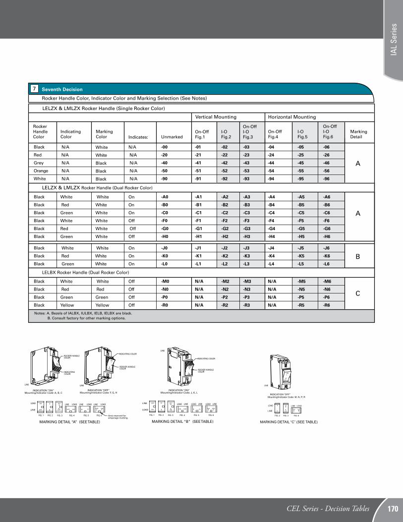
Seventh Decision7
Rocker Handle Color, Indicator Color and Marking Selection (See Notes)
Notes: 1. One or more descriptions may be used as required.2. When this is not used, table one may be substituted and U.S. thread and two lockwashers will be supplied. Unit will be rated at 250V (50/60Hz only.)3. VDE approved at 250Vac4. VDE approved at 415Vac
-A
-B
-C
-D
-E
-G
-K
-L
-M
-P
-U
-W -X
-1
-2
Standard hardware. No designation required.
Metric thread mounting inserts and terminals
Barrier
277V (50/60Hz only) (See note 3)
240/415V (50/60Hz only)
277V/480V (50/60Hz only) (See note 4)
Handle guard, (available in ZX, BX and snap-in versions only)
1/4 - 20 stud (M6 stud when -A option is selected)(<=70A requires -K, if >70A do not use -K)
Handle lock
Handle in opposite pole
Snap-in face plate adapter
120/240V 50/60Hz
Wire clamp supplied (VDE approved up toand including 16.0 amps)
Handle guard with no actuation feature (BX rocker only)
Silver 5/16" (.312") bullet
Gold 5/16" (.312") bullet
Optional
The shaded areas denote VDE and CCC(if applicable) Approval options. This approvalrequires the addition of a V at the end of thepart number. The V will be added to any partnumber formed entirely from shaded decisions.If non-shaded areas are selected, the unit will notbe VDE or CCC Approved, but other approvalsstill apply.
V = VDE and CCC Approved
Description
Note: CCC Approval is pending.
-0
-1
-1REC4
-1REC5
-1REG4
-1RS4
-1RLS4
-1RS5
-3
-4
Switch only (50, 70 or 100 amp switch)
Series
Series with auxiliary switch*.110 quick connect
Series with auxiliary switch*.187 quick connect
Series with auxiliary switch.110 quick connect
Series with alarm switch,electrical trip, .110 quick connect terminals
Series with alarm switch,electrical trip, .110 quick connect terminals (mid-trip only)
Series with alarm switch,electrical trip, .187 quick connect terminals
Shunt
Relay (not available in IEL/IELX)
This approval requires the addition of a C at the endof the part number. The unit will not be VDE Approved.
C = CCC Approved
MARKING DETAIL “A” (SEE TABLE)
LOAD LOAD
LINE
LOAD LOADLINE LINELINE
FIG. 2 FIG. 3 FIG. 4 FIG. 5FIG. 1 FIG. 6
OFF ON
ON
OFFOFF ON
ON
OFFO O O O
LINE LINE
ROCKER HANDLECOLOR
INDICATING COLOR
INDICATINGCOLOR
ROCKER HANDLECOLOR
INDICATION “ON”Mounting/Indicator Code: A, B, C
INDICATION “OFF”Mounting/Indicator Code: F, G, H
ONI
ONI
OOFF
OFFO
INDICATION “OFF”Mounting/Indicator Code: M, N, P, R
MARKING DETAIL “C” (SEE TABLE)
FIG. 2 FIG. 3 FIG. 6
LINE
LOAD LOADLINEO OFF ON
OO
ON
OFF
MARKING DETAIL “B” (SEE TABLE)
FIG. 2 FIG. 3 FIG. 4 FIG. 5FIG. 1 FIG. 6
OFFONON
OFF
OFFONON
OFFO O
O O
LINE
LOAD
LOAD LINE LOAD LINE LOAD LINE
LINE
ROCKERHANDLECOLOR
INDICATING COLOR
ONI
INDICATION “ON”Mounting/Indicator Code: J, K, L
OFFO
LINE
Second Decision
Single pole
Two pole
Three pole
Four pole*
1
11
111
1111
2
Poles
*Not available in toggle seal handle type.Consult factory for 5 and 6 pole IEL part number.
Internal Con�guration
Third Decision3
* Only one auxiliary switch is normally supplied on two or three pole units. Switch is located in the right-hand pole (viewed from terminal end) unless otherwise speci�ed.
1 2 3 4
IEL 1 - 1REC4- 61- 20.0 - 01 - V
5 7
Example:
Black
Yellow
Red
Blue
Green
Orange
White
-00
-10
-20
-30
-40
-60
-90
-01 (STD)
-11
-21
-31
-41
-61
-91
Seventh Decision7
Handle Color and Marking Selection
IAL, IUL, IEL, IALH,IULH, IELH - Toggle Handle
Marked* ON-OFF Color Unmarked I-O
Fifth Decision5
Rated Current
Use three numbers to print requiredcurrent value between .100 ampsminimum and 100 amps maximum.
For example, use:.100 or 2.00 or 10.0
The VDE (lth) will be 95% of theUL/CSA rated current.
Fourth Decision4
Frequency & Delay
Switch only
400Hz short delay
400Hz long delay
400Hz motor start
400Hz 150% instant trip
DC short delay
DC long delay
DC motor start
DC 125% instant trip
50/60Hz short delay
50/60Hz long delay
50/60Hz motor start
50/60Hz 125% instant trip
DC/60Hz short delay
DC/60Hz long delay
DC/60Hz motor start
DC/60 Hz 135% instant tripFor addition of inertial delay, add an ìFî to any delay numeral.
SW
-41
-42
-43
-49
-51
-52
-53
-59
-61
-62
-63
-69
-71
-72
-73
-79
Notes: A. Bezels of IALBX, IULBX, IELB, IELBX are black. B. Consult factory for other marking options.
Note: CCC Approval is pending.
Black
Red
Grey
Orange
White
-00
-20
-40
-50
-90
-01
-21
-41
-51
-91
-02
-22
-42
-52
-92
-03
-23
-43
-53
-93
-04
-24
-44
-54
-94
-05
-25
-45
-55
-95
-06
-26
-46
-56
-96
I-O Fig.2Unmarked
MarkingDetail
Seventh Decision7
Rocker Handle Color, Indicator Color and Marking Selection (See Notes)
Notes: 1. One or more descriptions may be used as required.2. When this is not used, table one may be substituted and U.S. thread and two lockwashers will be supplied. Unit will be rated at 250V (50/60Hz only.)3. VDE approved at 250Vac4. VDE approved at 415Vac
-A
-B
-C
-D
-E
-G
-K
-L
-M
-P
-U
-W -X
-1
-2
Standard hardware. No designation required.
Metric thread mounting inserts and terminals
Barrier
277V (50/60Hz only) (See note 3)
240/415V (50/60Hz only)
277V/480V (50/60Hz only) (See note 4)
Handle guard, (available in ZX, BX and snap-in versions only)
1/4 - 20 stud (M6 stud when -A option is selected)(<=70A requires -K, if >70A do not use -K)
Handle lock
Handle in opposite pole
Snap-in face plate adapter
120/240V 50/60Hz
Wire clamp supplied (VDE approved up toand including 16.0 amps)
Handle guard with no actuation feature (BX rocker only)
Silver 5/16" (.312") bullet
Gold 5/16" (.312") bullet
Optional
The shaded areas denote VDE and CCC(if applicable) Approval options. This approvalrequires the addition of a V at the end of thepart number. The V will be added to any partnumber formed entirely from shaded decisions.If non-shaded areas are selected, the unit will notbe VDE or CCC Approved, but other approvalsstill apply.
V = VDE and CCC Approved
Description
Note: CCC Approval is pending.
-0
-1
-1REC4
-1REC5
-1REG4
-1RS4
-1RLS4
-1RS5
-3
-4
Switch only (50, 70 or 100 amp switch)
Series
Series with auxiliary switch*.110 quick connect
Series with auxiliary switch*.187 quick connect
Series with auxiliary switch.110 quick connect
Series with alarm switch,electrical trip, .110 quick connect terminals
Series with alarm switch,electrical trip, .110 quick connect terminals (mid-trip only)
Series with alarm switch,electrical trip, .187 quick connect terminals
Shunt
Relay (not available in IEL/IELX)
This approval requires the addition of a C at the endof the part number. The unit will not be VDE Approved.
C = CCC Approved
IAL
Serie
s
Second Decision
Single pole
Two pole
Three pole
1
11
111
2
Poles
Fifth Decision 5
Rated Current
Use three numbers to print (.050 or 1.50 or 100)Value between .050 amps and 100 amps.
Fourth Decision4
Frequency and Delay
DC short delay
DC long delay
DC motor start
DC 125% instant trip
50/60Hz short delay
50/60Hz long delay
50/60Hz motor start
50/60Hz 125% instant trip
For addition of inertial delay, add an “F” to anydelay numeral. *Not available above 100 amps.
-51
-52
-53*
-59
-61
-62
-63
-69
The shaded areas denote VDE and CCC (if applicable)Approval options. This approval requires the addition ofa V at the end of the part number. The V will be added toany part number formed entirely from shaded decisions.If non-shaded areas are selected, the unit will not beVDE or CCC Approved, but other approvals still apply.
V = VDE and CCC Approved
The approval requires the addition of a C at the endof the part number. The unit will not be VDE Approved.
C = CCC Approved
1 2 3 4
LEL 1 - 1REC4 - 61 - 20.0 - 01 - V
5 7
Example:
Third Decision3
* Used only with mid-trip.
-1
-1REC4
-1REC5
-1REG4
-1RS4
-1RLS4
Series
Series with auxiliary switch.110 quick connect
Series with auxiliary switch .187 quick connect
Series with auxiliary switch (gold contacts).110 quick connect
Series with alarm switch, electrical trip,.110 quick connect
Series with alarm switch, electrical trip, .110 quick connect*
Internal Con�guration
Note: Other options available, consult factory.
One handle per unit
One handle per pole
One handle per unit, mid-trip indication
One handle per pole, mid-trip indication
One handle per unit, rocker, integral mounting
One handle per unit, rocker,mid-trip indication, integral mounting
One handle per unit, rocker,accidental-off protected
One handle per unit, rocker,mid-trip indication, accidental-offprotected
LEL
LELH
LML
LMLH
LELZX
LMLZX
LELBX
LMLBX
Select Type and Terminal
First Decision1
Type Terminal
Standard screw terminal,no designation required
Stud terminals
Clip terminals
Bullet terminals
K
C
B
Description
Sixth Decision
Metric thread mounting insertsand terminals
Barrier
240V 50/60Hz
Handle guard, (available in ZX, BX and snap-in versions only)
1/4 - 20 Stud (M6 Stud when -Aoption is selected) ( 50A requires -K, >50A do not use -K)
Handle Lock
Handle in opposite pole
Snap-in mounting plate adapter
120/240Vac, 5000 A.I.C., 70A max.2 pole only with barrier (VDE 250Vac)
125VDC
Handle guard with no actuate"off" feature (see detail C)
Silver 5/16" (.312") bullet
Gold 5/16" (.312") bullet
-A
-B
-F
-G
-K
-L
-M
-P
-U
-V
-X
-1
-2
6
Optional
Notes: 1. One or more descriptions may be used as required.2. When this decision is not used, decision 7 may be substituted and U.S. thread will be supplied. 3.If (M5 or M6) studs are required, use “A” only on an LELK.
Seventh Decision7
LEL Toggle Handle Color Selection
Black w/ white markings
Yellow w/ black markings
Red w/ white markings
Blue w/ white markings
Green w/ white markings
Orange w/ black markings
White w/ black markings
-01
-11
-21
-31
-41
-61
-91
See alternate 7th Decision for ZX and BX RockerHandles.
LEL DECISION TABLES
http://airpax.sensata.com/IAL/CEL/LEL Series - Operating Characteristics149 LEL Series - Decision Tables http://airpax.sensata.com167
Notes: The LEL family of circuit breakers are designed to meet 8mm creepage and clearance requirements for installation Category 111, pollution degree 3, Case A as measured in IEC 664. Intended for use in equipment designed to comply with IEC 380, 435, 601 AND VDE 0730, 0804 & 0805.
LINE LINE
FIG. 2 FIG. 3 FIG. 4 FIG. 5FIG. 1 FIG. 6
ROCKER HANDLECOLOR
INDICATING COLOR
INDICATINGCOLOR
ROCKER HANDLECOLOR
INDICATION “ON”Mounting/Indicator Code: A, B, C
LOAD LOAD
LINE
LOAD LOADLINE
INDICATION “OFF”Mounting/Indicator Code: F, G, H
LINELINE
Area reserved foramperage marking.
ONI
ONI
OOFF
OFFO
OFF ON
ON
OFFO OFF ON
O OO
ON
OFF
MARKING DETAIL “A” (SEE TABLE)
FIG. 2 FIG. 3 FIG. 4 FIG. 5FIG. 1 FIG. 6
OFF OFFOO
LINE LOAD LINE LOAD LINE LOAD LINE
MARKING DETAIL “B” (SEE TABLE)
OFFONONOFFON
ON
O OLOAD
LINE
ROCKER HANDLECOLOR
INDICATING COLOR
ONI
INDICATION “ON”Mounting/Indicator Code: J, K, L
OFFO
Notes: A. Bezels of IALBX, IULBX, IELB, IELBX are black. B. Consult factory for other marking options.
Black
Red
Grey
Orange
White
-00
-20
-40
-50
-90
-01
-21
-41
-51
-91
-02
-22
-42
-52
-92
-03
-23
-43
-53
-93
-04
-24
-44
-54
-94
-05
-25
-45
-55
-95
-06
-26
-46
-56
-96
I-O Fig.2Unmarked
MarkingDetail
Seventh Decision7
Rocker Handle Color, Indicator Color and Marking Selection (See Notes)
LELZX & LMLZX Rocker Handle (Single Rocker Color)
RockerHandleColor
IndicatingColor
MarkingColor Indicates:
On-Off Fig.1
On-Off I-OFig.3
On-Off I-OFig.6
I-O Fig.5
On-Off Fig.4
A
Vertical Mounting Horizontal Mounting
N/A
N/A
N/A
N/A
N/A
N/A
N/A
N/A
N/A
N/A
Black
Black
Black
White
Red
Green
White
White
White
On
On
On
-J0
-K0
-L0
-J1
-K1
-L1
-J2
-K2
-L2
-J3
-K3
-L3
-J4
-K4
-L4
-J5
-K5
-L5
-J6
-K6
-L6B
C
White
White
Black
Black
Black
LELZX & LMLZX Rocker Handle (Dual Rocker Color)
Black
Black
Black
Black
Black
Black
White
Red
Green
White
Red
Green
White
White
White
White
White
White
On
On
On
Off
Off
Off
-A0
-B0
-C0
-F0
-G0
-H0
-A1
-B1
-C1
-F1
-G1
-H1
-A2
-B2
-C2
-F2
-G2
-H2
-A3
-B3
-C3
-F3
-G3
-H3
-A4
-B4
-C4
-F4
-G4
-H4
-A5
-B5
-C5
-F5
-G5
-H5
-A6
-B6
-C6
-F6
-G6
-H6
Black
Black
Black
Black
White
Red
Green
Yellow
White
Red
Green
Yellow
Off
Off
Off
Off
-M0
-N0
-P0
-R0
N/A
N/A
N/A
N/A
-M2
-N2
-P2
-R2
-M3
-N3
-P3
-R3
N/A
N/A
N/A
N/A
-M6
-N6
-P6
-R6
-M5
-N5
-P5
-R5
A
LELBX Rocker Handle (Dual Rocker Color)
INDICATION “OFF”Mounting/Indicator Code: M, N, P, R
NOACTUATION
ACCESSOPTIONAL
HANDLEPOSITION “OFF”
WITH GUARD
HANDLEPOSITION “ON”WITH GUARD
MARKING DETAIL “C” (SEE TABLE)
FIG. 2 FIG. 3 FIG. 6
LINE
LOAD LOADLINE
O OFF ONOO
ON
OFF
MARKING DETAIL “A” (SEE TABLE)
LOAD LOAD
LINE
LOAD LOADLINE LINELINE
FIG. 2 FIG. 3 FIG. 4 FIG. 5FIG. 1 FIG. 6
OFF ON
ON
OFFOFF ON
ON
OFFO O O O
LINE LINE
ROCKER HANDLECOLOR
INDICATING COLOR
INDICATINGCOLOR
ROCKER HANDLECOLOR
INDICATION “ON”Mounting/Indicator Code: A, B, C
INDICATION “OFF”Mounting/Indicator Code: F, G, H
ONI
ONI
OOFF
OFFO
INDICATION “OFF”Mounting/Indicator Code: M, N, P, R
MARKING DETAIL “C” (SEE TABLE)
FIG. 2 FIG. 3 FIG. 6
LINE
LOAD LOADLINEO OFF ON
OO
ON
OFF
MARKING DETAIL “B” (SEE TABLE)
FIG. 2 FIG. 3 FIG. 4 FIG. 5FIG. 1 FIG. 6
OFFONON
OFF
OFFONON
OFFO O
O O
LINE
LOAD
LOAD LINE LOAD LINE LOAD LINE
LINE
ROCKERHANDLECOLOR
INDICATING COLOR
ONI
INDICATION “ON”Mounting/Indicator Code: J, K, L
OFFO
LINE
http://airpax.sensata.com/ IAL/CEL/LEL Series - Operating Characteristics 150LEL Series - Decision Tables
IAL
Serie
s
168
Second Decision
Single pole
Two pole
Three pole
1
11
111
2
Poles
Fifth Decision 5
Rated Current
Use three numbers in build (.050 or 1.50 or 100).
Required value between .050 amps minimumand 125 amps maximum.
Fourth Decision4
Frequency and Delay
DC short delay
DC long delay
DC motor start
DC 125% instant trip
For addition of inertial delay, add an “F” to anydelay numeral. Example: -51F *Not available above 100 amps.
-51
-52
-53*
-59
The shaded areas denote VDE and CCC(if applicable) approval options. Thisapproval requires the addition of a V atthe end of the part number. The V will beadded to any part number formedentirely from shaded decisions. Ifnon-shaded areas are selected, the unitwill not be VDE or CCC Approved, butother approvals still apply.
V = VDE and CCC Approved
The approval requires the addition of aC at the end of the part number. Theunit will not be VDE Approved.
C = CCC Approved
1 2 3 4
CEL 1 - 1REC4 - 51 - 20.0 - A - 01 - V
5 76
Example:
Third Decision3
* Only one auxiliary switch is normally supplied on twoand three pole units switch is located in the right handpole (viewed from terminal end). Note, aux switchfollowed by “R” indicates reverse mount option** Not available for 125 amp single pole
Internal Con�guration
Select Type and Terminal
First Decision1
Type Terminal
Standard screw terminal,no designation required
Stud terminals
Clip terminals
Bullet terminals
K
C
B
Description
Sixth Decision6
Optional
Notes: 1. One or more descriptions may be used as required.2. When this decision is not used, decision 7 may be substituted and U.S. thread will be supplied.
Seventh Decision7
LEL Toggle Handle Color Selection
Black w/ white markings
Yellow w/ black markings
Red w/ white markings
Blue w/ white markings
Green w/ white markings
Orange w/ black markings
White w/ black markings
-01
-11
-21
-31
-41
-61
-91
See alternate 7th Decision for ZX and BX RockerHandles.
CEL One handle per unit, UL489A Listed
CELZX One handle per unit, rocker handle, UL489A Listed
CELBX One handle per unit, �at rocker handle, UL489A Listed
CELH One handle per pole, UL489A Listed
CML Single pole only, one handle per unit mid-trip construction, UL489A Listed
-1REC4 Series with auxiliary switch .110 quick connect
-1RLS4 ** Series with auxiliary switch .110 quick connect, mid-trip only
-1REC5 Series with auxiliary switch .187 quick connect
-1RS4 ** Alarm switch, .110 quick connect
-1 Series
CMLZX Single pole only, one handle per unit, rocker handle w/ RLS aux switch, mid-trip construction, UL489A Listed
CMLBX Single pole only, one handle per unit, �at rocker handle w/ RLS aux switch, mid-trip construction, UL489A Listed
CMLH One handle per pole mid-trip construction, UL489A Listed
The approval requires the addition of aT at the end of the part number. Theunit will only be TÜV EN60947-2approved with a single pole,125 amp rating con�guration.
T = TÜV Approved
-A Metric thread mounting inserts and terminals
-G Snap-in mounting plate adapter with handle guard (ZX, BX and snap-in only)
-T 80VDC, 10000AIC, (required over 50A)
-V 125VDC
-1 Silver 5/16” (.312”) bullet
-2 Gold 5/16” (.312”) bullet
-K 1/4-20 Stud (M6 stud when metric option -A selected) 50A requires -K, >50A do not use -K
-B Barrier
-P Snap-in mounting plate adapter
CEL DECISION TABLES
http://airpax.sensata.com/IAL/CEL/LEL Series - Operating Characteristics149 CEL Series - Decision Tables http://airpax.sensata.com169
LINE LINE
FIG. 2 FIG. 3 FIG. 4 FIG. 5FIG. 1 FIG. 6
ROCKER HANDLECOLOR
INDICATING COLOR
INDICATINGCOLOR
ROCKER HANDLECOLOR
INDICATION “ON”Mounting/Indicator Code: A, B, C
LOAD LOAD
LINE
LOAD LOADLINE
INDICATION “OFF”Mounting/Indicator Code: F, G, H
LINELINE
Area reserved foramperage marking.
ONI
ONI
OOFF
OFFO
OFF ON
ON
OFFO OFF ON
O OO
ON
OFF
MARKING DETAIL “A” (SEE TABLE)
FIG. 2 FIG. 3 FIG. 4 FIG. 5FIG. 1 FIG. 6
OFF OFFOO
LINE LOAD LINE LOAD LINE LOAD LINE
MARKING DETAIL “B” (SEE TABLE)
OFFONONOFFON
ON
O OLOAD
LINE
ROCKER HANDLECOLOR
INDICATING COLOR
ONI
INDICATION “ON”Mounting/Indicator Code: J, K, L
OFFO
Notes: A. Bezels of IALBX, IULBX, IELB, IELBX are black. B. Consult factory for other marking options.
Black
Red
Grey
Orange
White
-00
-20
-40
-50
-90
-01
-21
-41
-51
-91
-02
-22
-42
-52
-92
-03
-23
-43
-53
-93
-04
-24
-44
-54
-94
-05
-25
-45
-55
-95
-06
-26
-46
-56
-96
I-O Fig.2Unmarked
MarkingDetail
Seventh Decision7
Rocker Handle Color, Indicator Color and Marking Selection (See Notes)
LELZX & LMLZX Rocker Handle (Single Rocker Color)
RockerHandleColor
IndicatingColor
MarkingColor Indicates:
On-Off Fig.1
On-Off I-OFig.3
On-Off I-OFig.6
I-O Fig.5
On-Off Fig.4
A
Vertical Mounting Horizontal Mounting
N/A
N/A
N/A
N/A
N/A
N/A
N/A
N/A
N/A
N/A
Black
Black
Black
White
Red
Green
White
White
White
On
On
On
-J0
-K0
-L0
-J1
-K1
-L1
-J2
-K2
-L2
-J3
-K3
-L3
-J4
-K4
-L4
-J5
-K5
-L5
-J6
-K6
-L6B
C
White
White
Black
Black
Black
LELZX & LMLZX Rocker Handle (Dual Rocker Color)
Black
Black
Black
Black
Black
Black
White
Red
Green
White
Red
Green
White
White
White
White
White
White
On
On
On
Off
Off
Off
-A0
-B0
-C0
-F0
-G0
-H0
-A1
-B1
-C1
-F1
-G1
-H1
-A2
-B2
-C2
-F2
-G2
-H2
-A3
-B3
-C3
-F3
-G3
-H3
-A4
-B4
-C4
-F4
-G4
-H4
-A5
-B5
-C5
-F5
-G5
-H5
-A6
-B6
-C6
-F6
-G6
-H6
Black
Black
Black
Black
White
Red
Green
Yellow
White
Red
Green
Yellow
Off
Off
Off
Off
-M0
-N0
-P0
-R0
N/A
N/A
N/A
N/A
-M2
-N2
-P2
-R2
-M3
-N3
-P3
-R3
N/A
N/A
N/A
N/A
-M6
-N6
-P6
-R6
-M5
-N5
-P5
-R5
A
LELBX Rocker Handle (Dual Rocker Color)
INDICATION “OFF”Mounting/Indicator Code: M, N, P, R
NOACTUATION
ACCESSOPTIONAL
HANDLEPOSITION “OFF”
WITH GUARD
HANDLEPOSITION “ON”WITH GUARD
MARKING DETAIL “C” (SEE TABLE)
FIG. 2 FIG. 3 FIG. 6
LINE
LOAD LOADLINE
O OFF ONOO
ON
OFF
MARKING DETAIL “A” (SEE TABLE)
LOAD LOAD
LINE
LOAD LOADLINE LINELINE
FIG. 2 FIG. 3 FIG. 4 FIG. 5FIG. 1 FIG. 6
OFF ON
ON
OFFOFF ON
ON
OFFO O O O
LINE LINE
ROCKER HANDLECOLOR
INDICATING COLOR
INDICATINGCOLOR
ROCKER HANDLECOLOR
INDICATION “ON”Mounting/Indicator Code: A, B, C
INDICATION “OFF”Mounting/Indicator Code: F, G, H
ONI
ONI
OOFF
OFFO
INDICATION “OFF”Mounting/Indicator Code: M, N, P, R
MARKING DETAIL “C” (SEE TABLE)
FIG. 2 FIG. 3 FIG. 6
LINE
LOAD LOADLINEO OFF ON
OO
ON
OFF
MARKING DETAIL “B” (SEE TABLE)
FIG. 2 FIG. 3 FIG. 4 FIG. 5FIG. 1 FIG. 6
OFFONON
OFF
OFFONON
OFFO O
O O
LINE
LOAD
LOAD LINE LOAD LINE LOAD LINE
LINE
ROCKERHANDLECOLOR
INDICATING COLOR
ONI
INDICATION “ON”Mounting/Indicator Code: J, K, L
OFFO
LINE
http://airpax.sensata.com/ IAL/CEL/LEL Series - Operating Characteristics 150CEL Series - Decision Tables
IAL
Serie
s
170
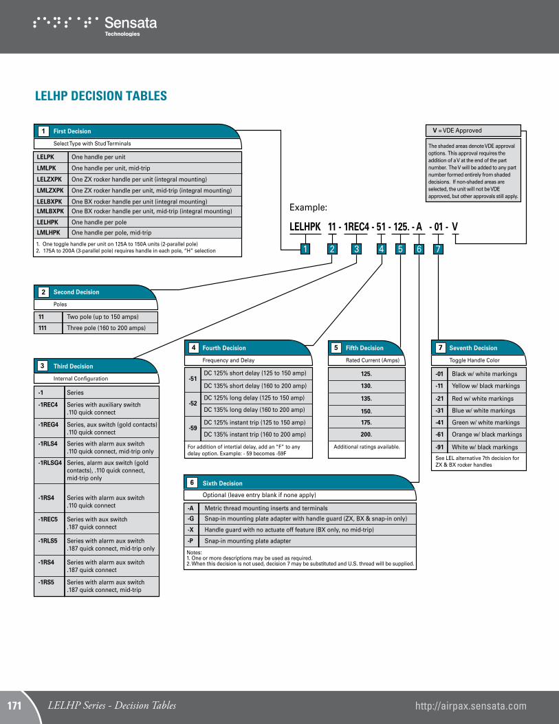
LELHP DECISION TABLES
LELPK One handle per unit
LMLPK One handle per unit, mid-trip
LELHPK One handle per pole
LMLHPK One handle per pole, mid-trip
LELZXPK One ZX rocker handle per unit (integral mounting)
LMLZXPK One ZX rocker handle per unit, mid-trip (integral mounting)
LELBXPK One BX rocker handle per unit (integral mounting)
LMLBXPK One BX rocker handle per unit, mid-trip (integral mounting)
LELHPK 11 - 1REC4 - 51 - 125. - A - 01 - V
Select Type with Stud Terminals
First Decision
Poles
Second Decision
11 Two pole (up to 150 amps)
111 Three pole (160 to 200 amps)
Internal Con�guration
Third DecisionFrequency and Delay
Fourth Decision
Rated Current (Amps)
Fifth Decision
-51DC 125% short delay (125 to 150 amp) 125.
130.
135.
150.
175.
200.
DC 135% short delay (160 to 200 amp)
-52DC 125% long delay (125 to 150 amp)
DC 135% long delay (160 to 200 amp)
-59DC 125% instant trip (125 to 150 amp)
DC 135% instant trip (160 to 200 amp)
7
Toggle Handle Color
Seventh Decision
Additional ratings available.
See LEL alternative 7th decision for ZX & BX rocker handles
1. One toggle handle per unit on 125A to 150A units (2-parallel pole)2. 175A to 200A (3-parallel pole) requires handle in each pole, “H” selection
-1 Series
-1REC4 Series with auxiliary switch .110 quick connect
-1REG4 Series, aux switch (gold contacts) .110 quick connect
-1RLSG4 Series, alarm aux switch (gold contacts), .110 quick connect, mid-trip only
-1RLS4 Series with alarm aux switch .110 quick connect, mid-trip only
-1RS4 Series with alarm aux switch .110 quick connect
-1RS4 Series with alarm aux switch .187 quick connect
-1RS5 Series with alarm aux switch .187 quick connect, mid-trip
-1REC5 Series with aux switch .187 quick connect
-1RLS5 Series with alarm aux switch .187 quick connect, mid-trip only
Example:
1 2 3 4 5 6 7
Sixth Decision6
Optional (leave entry blank if none apply)
Notes: 1. One or more descriptions may be used as required.2. When this decision is not used, decision 7 may be substituted and U.S. thread will be supplied.
-X Handle guard with no actuate off feature (BX only, no mid-trip)
-P Snap-in mounting plate adapter
-31 Blue w/ white markings
-41 Green w/ white markings
-61 Orange w/ black markings
-01 Black w/ white markings
-11 Yellow w/ black markings
-21 Red w/ white markings
-91 White w/ black markings
The shaded areas denote VDE approvaloptions. This approval requires theaddition of a V at the end of the partnumber. The V will be added to any partnumber formed entirely from shadeddecisions. If non-shaded areas areselected, the unit will not be VDEapproved, but other approvals still apply.
V = VDE Approved
For addition of intertial delay, add an “F” to any delay option. Example: - 59 becomes -59F
http://airpax.sensata.com/IAL/CEL/LEL Series - Operating Characteristics149 LELHP Series - Decision Tables http://airpax.sensata.com171
CELHPK 11 - 1REC4 - 51 - 125. - A - 01 - V
Select Type
First Decision
CELP One toggle handle per unit
Poles
Second Decision
11 Two pole (up to 150 amps)
111 Three pole (160 to 250 amps)
1111 Four pole (400 amps)
Internal Con�guration
Third Decision Frequency and Delay
Fourth Decision
Rated Current (Amps)
Fifth Decision
-51DC 125% short delay (101 to 150 amp) 125.
130.
135.
150.
175.
200.
400.
DC 135% short delay (160 to 250 amp)
-52DC 125% long delay (101 to 150 amp)
DC 135% long delay (160 to 250 amp)
-53DC 125% motor start (101 to 150 amp)
DC 135% motor start (160 to 250 amp)
-59DC 125% instant trip (101 to 150 amp)
DC 135% instant trip (160 to 250 amp)
7
Toggle Handle Color
Seventh Decision
Additional ratings available. See LEL alternative 7th decision for ZX & BX rocker handles
CELHP One toggle handle per pole
CMLHP One toggle handle per pole, mid-trip construction
CELZXP One rocker handle per unit
CELBXP One �at rocker handle per unit
1. One toggle handle per unit is available only on 101A to 200A (two parallel pole construction)2. 201A to 250A (three parallel pole constructions) require handles in each pole, “H” version �rst decision3. Unit supplied with bullet terminals will not have buss bar installed, unless requested, buss bar supplied standard to 150A only.4. One handle per unit is available for 100A to 200A (two parallel pole constructions) and 201A to 250A (three pole constructions) (ZX & BX versions only)5. 400 amps available with toggle handes only
-0 Switch only
-1 Series
-1REC4 Series with auxiliary switch .110 quick connect
-1RLS4 * Series with alarm aux. switch .110 quick connect, mid-trip only
-1RS4 * Series with alarm aux. switch .110 quick connect
-1RS4 * Series with alarm aux. switch .187 quick connect
-1REC5 Series with auxiliary switch .187 quick connect
-1RLS5 * Series with alarm aux. switch .187 quick connect, mid-trip only
1. Only one auxiliary switch is normally supplied on two and three pole units. Switch is located in the right hand pole (viewed from terminal end panel mount position).2. When more than one aux. switch is required, change the 1 (of the 1REC4) to 2 or 3. If switches are mixed, then use “2R” or 3R”.* Not available at 400 amps
Example:
Terminal
Standard screw terminal,no designation required
Stud terminals
Clip terminals
Bullet terminals
K
C
B
1 2 3 4 5 6 7
Sixth Decision6
Optional (leave entry blank if none apply)
Notes: 1. One or more descriptions may be used as required.2. When this decision is not used, decision 7 may be substituted and U.S. thread will be supplied.
-X Handle guard with no actuate off feature (BX only, no mid-trip)
-B Barrier
-01 Black w/ white markings
-11 Yellow w/ black markings
-21 Red w/ white markings
-31 Blue w/ white markings
-41 Green w/ white markings
-61 Orange w/ black markings
-91 White w/ black markings
The shaded areas denote VDE approvaloptions. This approval requires theaddition of a V at the end of the partnumber. The V will be added to any partnumber formed entirely from shadeddecisions. If non-shaded areas areselected, the unit will not be VDEapproved, but other approvals still apply.
V = VDE Approved
CELHP DECISION TABLES
http://airpax.sensata.com/ IAL/CEL/LEL Series - Operating Characteristics 150LELHP Series - Decision Tables