PT-516 Pumping Trap Installation and Maintenance IB-104-B This bulletin should be used by experienced personnel as a guide to the installation and maintenance of the PT-516 Pumping Trap or Pumping Trap Package. Selection or installation of equipment should always be accompanied by competent technical assistance. We encourage you to contact Armstrong or your local representative if further information is required. The maximum operating pressure for the PT-516 Pumping Trap is 150 psig (10.34 bar). The maximum design pressure for the PT-516 model (standard model design) is 150 psig @ 500° F or (10.34 bar @ 260° C). The PT-516 pumping trap weighs approximately 870 pounds (394 kg). Maximum back pressure is 80 psi (5.5 bar). Note: Although the maximum operating pressure is 150 psig (10.34 bar), Armstrong Fluid Handling recommends that the motive pressure be set to 30 psig (2.07 bar) above the back pressure. This will provide optimum performance and reduce venting time between cycles. Pump Trap Operation 1. At start up, the float lies at its lowest position in the bottom of the tank. The motive inlet valve is closed and the vent valve is open. 2. Liquid enters the pump body by gravity through the inlet check valve. Back pressure (typically) holds the discharge check valve closed. The float becomes buoyant and begins rising. 3. Continued rising of the float, through linkage, increases spring compression until it reaches its upper tripping point. The linkage then snaps upward over center. This upward motion opens the inlet valve and closes the vent valve simultaneously. 4. Steam, air or gas enters the inlet valve and builds pressure inside the pumping trap. This pressure will close the inlet check valve and force liquid out through the discharge check valve as it opens. 5. The discharge cycle will lower the float level until it reaches its lower tripping point. The compression spring will cause the mechanism to snap over its center point downward. This action will close the motive inlet valve and simultaneously open the vent valve. 6. Venting of pressure from the body opens the inlet check valve and closes the discharge check valve. Liquid now flows by gravity through the inlet check valve into the pumping trap body as a new cycle begins.
Transcript
PT-516 Pumping TrapInstallation and Maintenance
IB-104-B
This bulletin should be used by experienced personnel as a guide to the installation and maintenance of the PT-516 Pumping Trap or Pumping Trap Package. Selection or installation of equipment should always be accompanied by competent technical assistance. We encourage you to contact Armstrong or your local representative if further information is required.
The maximum operating pressure for the PT-516 Pumping Trap is 150 psig (10.34 bar). The maximum design pressure for the PT-516 model (standard model design) is 150 psig @ 500° F or (10.34 bar @ 260° C). The PT-516 pumping trap weighs approximately 870 pounds (394 kg). Maximum back pressure is 80 psi (5.5 bar).
Note: Although the maximum operating pressure is 150 psig (10.34 bar), Armstrong Fluid Handling recommends that the motive pressure be set to 30 psig (2.07 bar) above the back pressure. This will provide optimum performance and reduce venting time between cycles.
Pump Trap Operation1. Atstartup,thefloatliesatitslowestpositioninthebottomofthetank.Themotiveinletvalveis closed and the vent valve is open.
2. Liquid enters the pump body by gravity through the inlet check valve. Back pressure (typically) holdsthedischargecheckvalveclosed.Thefloatbecomesbuoyantandbeginsrising.
3. Continuedrisingofthefloat,throughlinkage,increasesspringcompressionuntilitreachesits upper tripping point. The linkage then snaps upward over center. This upward motion opens the inlet valve and closes the vent valve simultaneously.
4. Steam, air or gas enters the inlet valve and builds pressure inside the pumping trap. This pressure will close the inlet check valve and force liquid out through the discharge check valve as it opens.
5. Thedischargecyclewilllowerthefloatleveluntilitreachesitslowertrippingpoint.The compression spring will cause the mechanism to snap over its center point downward. This action will close the motive inlet valve and simultaneously open the vent valve.
6. Venting of pressure from the body opens the inlet check valve and closes the discharge check valve.Liquidnowflowsbygravitythroughtheinletcheckvalveintothepumpingtrapbodyasa new cycle begins.
2
Figure 2
Suggested Installation of Accessories
Gauge Glass Assembly:The Bronze Gauge Glass Assembly will have male NPT connections.The PT-516 requires additional parts to mount the gauge glass. Two (2) 1/2” x 3" nipples and two (2) 1/2” couplings.
Cycle Counter:There is a 1/4” connection on top of the cap where the cycle counter can be mounted. One (1) 1/4” pigtail siphon and 1/4" isolation valve are required. It is very important that a steel siphon or “pig tail” be used prior to the cycle counter to avoid any damage to the cycle counter.
Installation
Note: It is important to check all fittings before start up to ensure that none loosened during shipment.
Motive Ball
Motive Seat
Motive Pin
Bolt 3/8-16x1.25
Frame Plate
Linkage
Actuator
Float Arm
Retaining Ring
Spacer
Nut 1/2-13
Bolt 1/2-13x5
Bushing
Spring Arm
Valve Holder
Vent Valve
Vent Seat
FH-1397Nameplate
2" NPTVent
2" NPTMotive Inlet
FH-2165Cap Flange
FH-2159Gasket
4x FH-2157Bolt
FH-2161Nipple
FH-2169MechanismAssembly
2x FH-1398Drive Screw
FH-21701/4" NPTPipe Plug
FH-2150Float
3
Filling Head:InstallthePT-516belowtheequipmentbeingdrained.Aminimumfillingheadof24"isrequiredfor the PT-516. Filling head is measured from the bottom of the receiver or reservoir pipe to the topofthePT-516cap.Allinletfittingsmustbefullportedandmatchthepump’sliquidinletconnectionsize.Greaterfillheadsmayincreasethecapacityofthepump.ReferenceCatalog326 for capacities.
Liquid Reservoir:Liquidflowingfromtheequipmentbeingdrainedmustbestoredduringthepump’sdischargecycle.A liquid reservoir (pipe reservoir) or vented receiver should be installed in a horizontal plane to preventfloodingofequipment.PleasecontactyourlocalArmstrongrepresentativeforquestionsregarding reservoir sizing or reference sizing data from Catalog 326.
Check Valves:Note: The PT-516 will not function without inlet and discharge check valves. Connect the Armstrong suppliedcheckvalvestothepump.ThePT-516hastwo(2)4"flangedconnections.The use of Armstrong supplied check valves is necessary to ensure the pump will attain maximum capacities. Best performance is achieved when a minimum of horizontal pipe is used before the inlet check valve.
The following guidelines apply if the PT-516 is installed without Armstrong supplied check valves.
1. Both inlet and outlet check valves should be 4" in-line wafer style with a carbon steel body and stainless steel trim, Class 150. All stainless steel 4" in-line wafer check valves may also be used.
Motive Inlet Piping:Connect the motive force piping (steam, air, or gas) to the inlet connection on the PT-516 cap. Proper piping and trapping of the motive supply line must include a strainer, check valve, properly sized drip leg with mud pocket and drip trap. The motive supply line must be a minimum of 2". The drip trap discharge line should be connected to the reservoir piping or vented receiver when practical.
Note: The motive inlet connection is the one furthest away from the 1/4” NPT connection on top of the cap.
Maximum operating pressure for the PT-516 is 150 psig (10.34 bar). A pressure reducing valve must be used when the motive pressure exceeds 150 psig (150.34 bar). It is also recommended that the motive pressure be set a minimum of 20 psig (1.3 bar) above the back pressure but highenoughtoensurecapacity.ReferenceCatalog326forcapacityratings.ThePRVshouldbe installed a minimum of 10 feet from the pump. If less than four feet is necessary, then the installation of an accumulator pipe is warranted.
Installation of a safety relief valve and pressure gauge is recommended on the motive force supply line. The relief valve should be set for 150 psig (10.34 bar).
Vent Connection (“Open” System-vented to atmosphere):Pipingfromthepump’scapconnectionshouldbeinstalledverticallyupwardwhenpossibleandunrestricted. The minimum size of this vent piping should be 2". If piping travels longer than 10 feet, the piping should be expanded to a minimum of 3". If a horizontal run is required, this line should be pitched toward the pump trap in order to be self-draining.
4
Note: The vent connection is the one closest to the ¼” NPT connection.
Vent Connection (“Closed-loop” system):Fromthepump’sventconnection,theequalizinglineshouldberoutedtothetopoftheequipmentbeing drained or its outlet piping immediately after the heat exchange equipment. An Armstrong thermostatic air vent is recommended (for steam) at the high point of the exhaust line. Piping of the equalizing line should be a minimum of 2" (50 mm) diameter and must be pitched in order to be self-draining.
Note: The vent line may be plumbed back in to the heat exchange equipment if that equipment has less than a 1/2 psi pressure drop. Otherwise, the vent line should be plumbed back in to the top of the receiver.
If pressure from the equipment being drained could possibly exceed back pressure against the pump,aproperlysizedfloatandthermostatictrapmustbeinstalledbetweenthepumpanddischarge check valve.
Packaged Receiver Vent Connections: The receiver vent must be unrestricted and atmosphericallyventedunlessanASMEcodedtankisspecified.
Packaged Pump Trap Vent Connections:Pipingfromthepump’sventconnectionshouldbeinstalled upward to connect with the receiver vent line, and be a minimum of 2 inches (50 mm) in diameter. Packaged Connections:Note: All receiver tanks should be operated at atmospheric pressure (vented) unless the package was ordered with an ASME coded tank.
A pumping trap receiver package designates the number of pumps with a “S” for single (one pump), “D” for duplex (two pumps), “T” for triple (three pumps) and “Q” for quad (four pumps). For example: SPT-516RPorDPT-516RP.The“RP”attheendofthemodelnumbermeansreceiverpackage.
TheSPT-516RPorsinglepumpreceiverpackagehasa130gallon(491liter)receivertankwithone(1)8"150#flangedventconnection,one(1)6"150#flangedinletconnection,one(1)4"150#flangedinletconnection,one(1)4"150#flangedsideinletconnectionandone(1)2"NPTconnection on top.
2. Slowly open motive force (steam, air or inlet gas) supplying the PT-516 providing pressure to the inlet valve. Check for proper operation of the drip trap on the motive line if using steam.
3. Open vent isolation valve.
4. Open isolation valves leading to the pump liquid inlet and discharge lines.
5. Open any additional valves upstream allowing liquid to enter the PT-516 from the equipment being drained. Pump will begin discharging when body is nearly full.
6. Properoperationincludesanaudibleexhaustaftereachpumpcycle.Ifoperationdoesn’tseem proper, recheck the installation and start-up procedure. Contact Armstrong or your local ArmstrongRepresentativeifnecessary.
7. Armstrongstronglyrecommendstheuseofoverflowpipingonreceivertanksinopen conden- sate return systems,onALLpumptrapskids.Properlyinstalledoverflowpipingincreases theefficiencyofthesystem,whileaddressingpotentialsafetyissuesinvolvedwiththeuninten- tionalescapeofhotcondesate.Onesuggestionwouldbetheuseofa"P"-traptoformasuffi- cient water seal. Be sure to check that a water seal has formed to prevent venting of steam throughtheoverflowconnectionduringoperation.
Maintenance1. Close the valves in the motive supply, vent, condensate and discharge lines. Also, close the shut-off valve(s) to the receiver for packaged units. Make sure that the PT-516 is completely relieved of pressure before breaking any connections.
2. Break motive inlet and vent (all cap) connections.
3. Removecapassemblyandinspectmechanismforfreedomofmovement.Removeanydirtor scale inhibiting the motion of the mechanism. IMPORTANT NOTE: The PT-516 mechanism weighs approximately 120 lbs. You will need a forklift or overhead lift to remove the mechanism from the pump body. The withdrawal distance is approximately 18 inches (457mm).
4. Checkthefloatforpinholeleaks,dentsorcorrosion.Immerseinhotwaterandlookforair bubbles to detect pinhole leaks.
7. Inspect inlet and discharge check valves for freedom of movement. Ensure that both check valves seat properly. It is important that both check valves are able to fully seat. Foreign material or debris may damage seating surfaces.
6
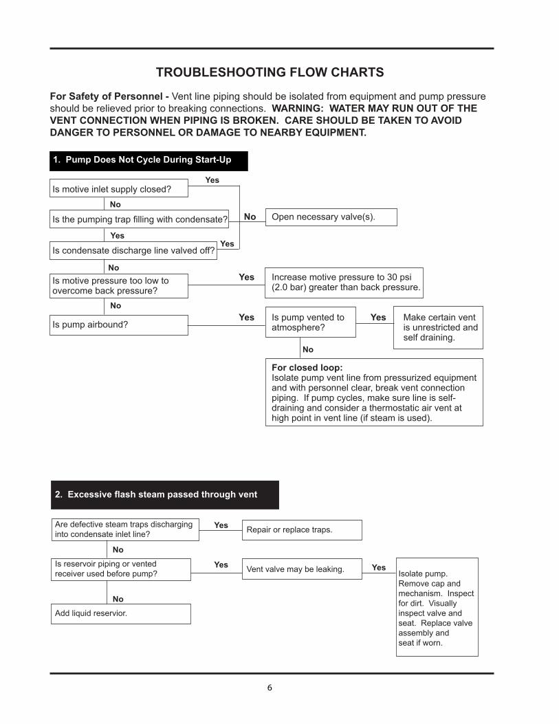
No Open necessary valve(s).
Yes Increase motive pressure to 30 psi (2.0 bar) greater than back pressure.
Yes Is pump vented to Yes Make certain vent atmosphere? is unrestricted and self draining.
For closed loop: Isolate pump vent line from pressurized equipment and with personnel clear, break vent connection piping. If pump cycles, make sure line is self- draining and consider a thermostatic air vent at high point in vent line (if steam is used).
Is motive inlet supply closed?
Isthepumpingtrapfillingwithcondensate?
Is condensate discharge line valved off?
Is motive pressure too low to overcome back pressure?
Is pump airbound?
No
No
Yes
No
No
TROUBLESHOOTING FLOW CHARTS
For Safety of Personnel - Vent line piping should be isolated from equipment and pump pressure should be relieved prior to breaking connections. WARNING: WATER MAY RUN OUT OF THE VENT CONNECTION WHEN PIPING IS BROKEN. CARE SHOULD BE TAKEN TO AVOID DANGER TO PERSONNEL OR DAMAGE TO NEARBY EQUIPMENT.
1. Pump Does Not Cycle During Start-Up
Yes
Yes
Are defective steam traps discharging into condensate inlet line?
Is reservoir piping or vented receiver used before pump?
Add liquid reservior.
2. Excessive flash steam passed through vent
Isolate pump. Removecapandmechanism. Inspect for dirt. Visually inspect valve and seat.Replacevalveassembly and seat if worn.
No
No
Yes
Yes
Repairorreplacetraps.
Vent valve may be leaking. Yes
7
Yes
Yes
Yes
Yes
Yes
Yes
3. Pump cycles but equipment or piping is flooded NOTE: See Catalog 326 for sizing.
Install additional pump.
Lower pump as necessary.
Increase motive pressure as required.
Verify pump rated capacity per Catalog 326 at actual conditions and increase motive pressure as required.
Usefullportedfittings,openallvalvesfullyand eliminate any blockages.
Isolate and inspect check valve and cleanor replace as required.
Ismotivepressureinsufficientforpump to provide rated capacityper Catalog 326?
Is back pressure greater than anticipated?
Is condensate inlet line restricted?
Is inlet check valve hanging open?
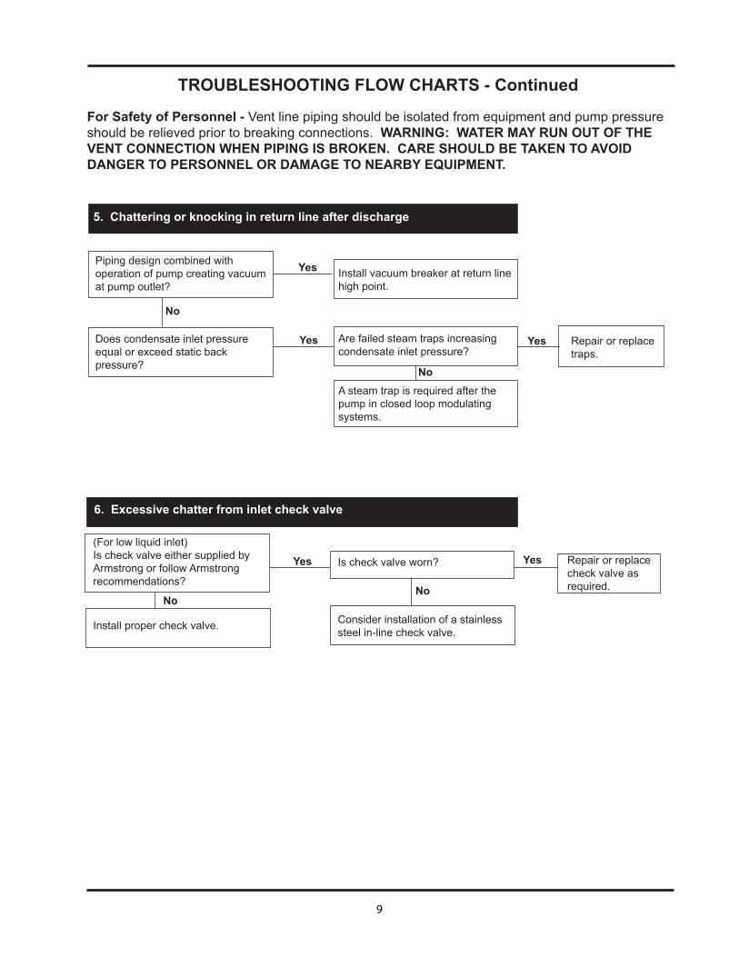
TROUBLESHOOTING FLOW CHARTS - Continued
For Safety of Personnel - Vent line piping should be isolated from equipment and pump pressure should be relieved prior to breaking connections. WARNING: WATER MAY RUN OUT OF THE VENT CONNECTION WHEN PIPING IS BROKEN. CARE SHOULD BE TAKEN TO AVOID DANGER TO PERSONNEL OR DAMAGE TO NEARBY EQUIPMENT.
8
Replace Required Parts
Vent line may be vapor locked. Ensure it's self draining.
Open valve.
Isolate and inspect check valve and clean or replace as required.
4. Pump stops cycling and equipment is flooded
No
No
No
No
Yes
Yes
Yes
Yes
Yes
Yes
Yes
Increase motive pressure to 30 psi (2.0 bar) greater than back pressure.
Check for a closed downstream valve or line blockage.
Isolate and inspect check valve and clean or replace as required.
Removepumpcap/mechanism.Visually inspect valve and seat. Replacevalveassemblyandseatif worn.
Is the spring broken?
Contact local Armstrong Representative
Yes
No
No
No
No
Yes
TROUBLESHOOTING FLOW CHARTS
For Safety of Personnel - Vent line piping should be isolated from equipment and pump pressure should be relieved prior to breaking connections. WARNING: WATER MAY RUN OUT OF THE VENT CONNECTION WHEN PIPING IS BROKEN. CARE SHOULD BE TAKEN TO AVOID DANGER TO PERSONNEL OR DAMAGE TO NEARBY EQUIPMENT.
No
Ismotivepressureinsufficient?
Are motive pressure and staticback pressure at pump equal?
Is discharge check valve stuck closed?
Isolate vent line from equipment being drained and break piping at pump vent connection.
With condensate inlet and discharge lines closed and motive pressure line slowly opened, does leakage occur at vent connection?
Slowly open condensate inlet line and, with motive pressure line open, observe vent connection (keeping personnel clear). Does liquid run out vent connection?
If mechanism tripped, open liquid discharge line. Does pump work normally?
If mechanism does not cycle, is an upstream valve closed?
Inlet check valve is stuck closed.
9
Yes Repairorreplace traps.
5. Chattering or knocking in return line after discharge
Piping design combined with operation of pump creating vacuum at pump outlet?
Does condensate inlet pressure equal or exceed static back pressure?
Yes
Yes
No
Is check valve worn?
Consider installation of a stainless steel in-line check valve.
No
6. Excessive chatter from inlet check valve
(For low liquid inlet)Is check valve either supplied by Armstrong or follow Armstrong recommendations?
Install proper check valve.
Install vacuum breaker at return line high point.
Are failed steam traps increasing condensate inlet pressure?
A steam trap is required after the pump in closed loop modulating systems.
No
Repairorreplace check valve as required.
YesYes
TROUBLESHOOTING FLOW CHARTS - Continued
For Safety of Personnel - Vent line piping should be isolated from equipment and pump pressure should be relieved prior to breaking connections. WARNING: WATER MAY RUN OUT OF THE VENT CONNECTION WHEN PIPING IS BROKEN. CARE SHOULD BE TAKEN TO AVOID DANGER TO PERSONNEL OR DAMAGE TO NEARBY EQUIPMENT.
No
Special Warranty Periods are as follows:Three (3) years after installation, but in no event longer than 39 months after shipment from Armstrong's factory. PT100, 200, 300, 3500 and 400 Series Standard Pumping Traps. PT100, 200, 300, 3500 and 400 Series Replacement Cap Assemblies and Rescue Cap ®.
Limited Warranty and Remedy
Armstrong International, Inc. (“Armstrong”) warrants to the original user of those products supplied by it and used in the service and in the manner for which they are intended, that such products shall be free from defects in material and workmanship for a period of one (1) year from the date of installation, but not longer than 15 months from the date of shipment from the factory, [unless a Special Warranty Period applies, as listed below]. This warranty does not extend to any product that has been subject to misuse, neglect or alteration after ship¬ment from the Armstrong factory. Except as may be expressly provided in a written agreement between Armstrong and the user, which is signed by both parties, Armstrong DOES NOT MAKE ANY OTHER REPRESENTATIONS OR WARRANTIES, EXPRESS OR IMPLIED, INCLUDING, BUT NOT LIMITED TO, ANY IMPLIED WARRANTY OF MERCHANTABILITY OR ANY IMPLIED WARRANTY OF FITNESS FOR A PARTICULAR PURPOSE.
The sole and exclusive remedy with respect to the above limited warranty or with respect to any other claim relating to the products or to defects or any condition or use of the products supplied by Armstrong, however caused, and whether such claim is based upon warranty, contract, negligence, strict liability, or any other basis or theory, is limited to Armstrong’s repair or replacement of the part or product, excluding any labor or any other cost to remove or install said part or product, or at Armstrong’s option, to repayment of the purchase price. As a condition of enforcing any rights or remedies relating to Armstrong products, notice of any warranty or other claim relating to the products must be given in writing to Armstrong: (i) within 30 days of last day of the applicable warranty period, or (ii) within 30 days of the date of the manifestation of the condition or occurrence giving rise to the claim, whichever is earlier. IN NO EVENT SHALL ARMSTRONG BE LIABLE FOR SPECIAL, DIRECT, INDIRECT, INCIDENTAL OR CONSEQUENTIAL DAMAGES, INCLUDING, BUT NOT LIMITED TO, LOSS OF USE OR PROFITS OR INTERRUPTION OF BUSINESS. The Limited Warranty and Remedy terms herein apply notwithstanding any contrary terms in any purchase order or form submitted or issued by any user, purchaser, or third party and all such contrary terms shall be deemed rejected by Armstrong.
Armstrong Steam and Condensate Group816 Maple Street, Three Rivers, MI 49093 – USA Phone: (269) 273-1415 Fax: (269) 278-6555 armstronginternational.com
Designs, materials, weights and performance ratings are approximate and subject to change without notice.Visit www.armstronginternational.com for up-to-date information.