Table of ContentsUNPACKING...................................................................................................................................... 1
TABLE 1: I/O WIRING AND CORRESPONDING LED DESIGNATORS ........................................................... 5 FIGURE 1: MOUNTING TEMPLATE......................................................ERROR! BOOKMARK NOT DEFINED. FIGURE 2: ISOLATION BUFFER...........................................................ERROR! BOOKMARK NOT DEFINED. FIGURE 3: IB6 FORM A OPERATION ..................................................ERROR! BOOKMARK NOT DEFINED. FIGURE 4: IB6 FORM C OPERATION ..................................................ERROR! BOOKMARK NOT DEFINED.
Document No. 821-0001-00 Rev. 0 11
UNPACKING The shipping carton should contain the following:
• IB6 Series Isolation Buffer (Board Assembly # 272-0003-XX) Be sure to inspect the IB6 for any shipping damages. If damage is evident, notify the carrier accordingly, and contact TransData.
INSTALLATION INSTRUCTIONS
1. Select a suitable mounting location for the IB6.
2. Using Error! Reference source not found. as a reference, drill 3/16” holes.
3. Mount the IB6 using 4 appropriate #8 screws. Secure the screws tightly.
4. Disable AC power source. If 120VAC power supply is used, connect the AC power source to the IB6 using 16 gauge stranded wire with an insulation rating of at least 300 volts. If 208VAC, 240VAC or 277VAC power supply is used, then the wire insulation rating should be at least 600 volts.
5. If the IB6 is not mounted to a grounded surface, then TransData recommends connecting 16 AWG or larger wire between one of the mounting plate screws and a suitable earth ground to insure proper operation of the IB6 device.
Installation
1
To install an IB6, follow these steps:
NOTE
Due to the solid-state design and no moving parts, the IB6 series is environmentally friendly and can be
mounted in any position.
Document No. 821-0001-00 Rev. 0 22
WHAT IS AN IB6? The IB6 is a solid state isolation buffer with up to three Form A or Form C pulse inputs and up to six Form A or Form C solid state pulsed outputs. This device is available in five different model configurations to fit any utility metering application.
The IB6 provides a pulse distribution point to various devices in remote locations. The buffer is designed to isolate and protect network components for safety and security. It can be used for both pulse replication and pulse isolation applications, where a utility needs to isolate their billing meter’s pulsed output from a customer’s energy management system, RTU, Load Profile Recorder, or some other pulse collecting device. The IB6 can also replicate two or three pulsed inputs, providing the same pulse to several different devices. Reference Error! Reference source not found..
ApplicationsApplications The IB6 can be utilized in the following applications:
• Isolation for substation pulse inputs/outputs
• Meter pulse isolation and pulse replication
• DC pilot wire signaling for long distances
• Pulse bounce filtering
FeaturesFeatures The IB6 provides the following features:
• Up to three Form A or Form C inputs accepting contact closures or open collector inputs
• Power supply accepting 120 - 277 VAC, selectable using PCB header shunts
Mechanical HardwareMechanical Hardware The printed circuit board is fastened to an aluminum plate by means of four standoffs and #4 screws. A clear dust cover protects the electronics. As an option, a sealable dust cover or a NEMA 3R security enclosure can be provided.
Electrical HardwareElectrical Hardware
InputsInputs The IB6 provides one to three pulse input connections, which can be wired to any Form A or Form C pulse source, such as an electric meter pulse initiator output. Headers TB7, TB8, and TB9 control the type of input that will be accepted on Input Channels 1, 2, and 3. Header TB7 controls Input Channel 1, header TB8 controls Input Channel 2, and header TB9 controls Input Channel 3. The shunt installed at the header pins labeled “C”, sets the respective input to accept a Form C contact closure. The shunt installed at the header pins labeled “A”, sets the respective input to accept a Form A contact closure or open collector. Reference Error! Reference source not found..
These inputs provide the following features for the IB6:
• Form A (two-wire) or Form C (three-wire) operation, which are independently field configurable for both inputs using PCB header shunts.
• Color-coded LED’s indicate pulse reception for both the “Y” and “Z” of each input.
• The inputs are designed to accept dry relay contacts or open collector pulse sources. An input wetting voltage of 5.5 to 8.5 VDC open circuit with a short circuit current capability of 4.2 to 5.2mA.
• Input pulse rates up to 10 pulses per second are permissible.
Hardware
3
NOTE
Any combination of Form A or Form C can be used on each input, in the order required, by using PCB header shunts.
Document No. 821-0001-00 Rev. 0 44
OutputsOutputs The outputs are optically isolated FET transistors, which are rated at 270V peak AC or DC and 150mA maximum DC or RMS current. The isolation rating is 1500VRMS. Color-coded LED’s indicate the transmission of IB6 pulses on both the “Y” and “Z” of each output. See Table 1: I/O Wiring and Corresponding LED Designators for terminal and LED designations.
Wiring ConnectionsWiring Connections User terminations are facilitated using 300V, wire clamp, terminal strips that will accommodate 18 to 12 AWG wire. The IB6 is designed to operate with input wire lengths of up to 2500 feet when using twisted pair, or shielded twisted pair, 18 to 12 AWG copper wire, or with a maximum input wire impedance of 1.5kΩ if other wire type is used. Terminal block designations for the input and output connections as well as AC power are labeled on the printed circuit board silkscreen as shown in Error! Reference source not found..
Meter Input WiringMeter Input Wiring
If Form A inputs are used, “1K” and “1Y” are input one, “2K” and “2Y” are input two, and “3K” and “3Y” are input three. Reference Error! Reference source not found..
If Form C inputs are used, “1K”, “1Y”, and “1Z” are input one, “2K”, “2Y”, and “2Z” are input two, and “3K”, “3Y”, and “3Z” are input three. Reference Error! Reference source not found..
Output WiringOutput Wiring
Each output provides a “K”, “Y”, and “Z” terminal. Form C operation requires a “K”, “Y”, and “Z” connection for each output. Form A output connections are all achieved by using only the “K” and “Y” or “K” and “Z” terminals.
Power SupplyPower Supply The AC input to the power supply is transformer isolated and accommodates 120 - 277 VAC at a maximum of 5.5 VA of burden. Input voltage is selectable by installing a PCB header shunt on header J1, J2, J3, or J4.
WARNING!
To prevent shock, always disconnect power before selecting voltage.
Document No. 821-0001-00 Rev. 0 55
INPUT/OUTPUT RELATIONSHIPS Each of the following models is factory mapped for two outputs per input:
IB6-12 1 Form A or Form C input and 2 Form C outputs
IB6-24 2 Form A or Form C input and 4 Form C outputs IB6-36 3 Form A or Form C input and 6 Form C outputs
Each of the following models is factory mapped for three outputs per input:
IB6-13 1 Form A or Form C input and 3 Form C outputs IB6-26 2 Form A or Form C input and 6 Form C outputs
Table 1: I/O Wiring and Corresponding LED Designators
Document No. 821-0001-00 Rev. 0 66
Figure 1: Mounting Template
Document No. 821-0001-00 Rev. 0 77
Figure 2: Isolation Buffer
Document No. 821-0001-00 Rev. 0 88
Figure 3: IB6 Form-A Operation
Document No. 821-0001-00 Rev. 0 99
Figure 4: IB6 Form-C Operation
Document No. 821-0001-00 Rev. 0 1010
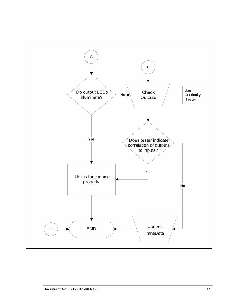
TROUBLESHOOTING
Troubleshooting
5 UNIT
INOPERATIVE
Check ACPower
Is AC input voltagecorrect?
Check ACsource
Verify wiringconnections
Is AC source good?
Yes
Repair ACsource
No
Check inputLEDs
Yes
A
Yes
Use DVM tocheck voltage at
TB1 pins 1 & 2AC
No
Does tester indicatecontact closure and
opening?
TroubleshootInput SourceNo
C
Do input LEDsilluminate?
Check inputsUseContinuity Tester
No
Yes
C
Document No. 821-0001-00 Rev. 0 1111
END
A
CheckOutputs
Yes Does tester indicatecorrelation of outputs
to inputs?
ContactAPTECH
B
C
Unit is functioningproperly.
Do output LEDsilluminate?
UseContinuity Tester
No
Yes
No
TransData
Document No. 821-0001-00 Rev. 0 1212
SPECIFICATIONS
Power RequPower Requirementsirements Voltage 120 - 277 VAC ±20% Frequency 50/60 Hz
Burden Less than 5.5 VA AC Input Surge Suppression 1.5 Joules/26 Amps
InputsInputs Number of Inputs Up to three Form C (three-wire) or Form A (two-wire) Signal Conditioning Voltage 5.5 to 8.5VDC open circuit
Current Output 4.9 to 5.2mA short circuit current max.
OutputsOutputs Number of Outputs Up to six Form C (three-wire) or Form A (two-wire) Voltage 270 Volts DC or peak AC maximum Current 150mA
Capacity 20VA DC or 14VA AC RMS Max. Pulse Rate 10 pulses per second per channel
Environmental and MechanicalEnvironmental and Mechanical Temperature -40° to +85° Celsius Humidity 5 to 95% non-condensing Mounting Plate The IB6 is fastened to an aluminum plate. Dust
cover included. Sealable cover or NEMA 3R security enclosure-optional.
ApprovalsApprovals • Approved by the Legal Metrology Branch (LMB) of Industry Canada (IC), Approval #E-281.
Specifications
6 CC
Document No. 821-0001-00 Rev. 0 1313
INDEX
A Applications ................................................................................................................................................................................ 2
E Electrical Hardware .................................................................................................................................................................... 3
F Features ...................................................................................................................................................................................... 2
I Input/Output Relationships ....................................................................................................................................................... 5
M Mechanical Hardware ................................................................................................................................................................. 3
Meter Input Wiring...................................................................................................................................................................... 4
O Output Wiring.............................................................................................................................................................................. 4
P Power Supply .............................................................................................................................................................................. 4
S Specifications............................................................................................................................................................................12
T Troubleshooting........................................................................................................................................................................10
U Unpacking ................................................................................................................................................................................... 1
W What is an IB6? ........................................................................................................................................................................... 2