IBIS: ATestbed for the Evolution of Intelligent Broadband Networks toward TINA Marc0 Listanti, University of Roma "La Sapienza" Stefan0 Salsano, CoRiTeL This article analyzes a possible path for the evolution of ABSTRACT telecommunication networks toward open distributed architec- tures like the TINA-C architecture. The results of a research project called IBIS carried out within the CoRiTeL laboratory are presented. The IBIS project starts from the activities of the ACTS project INSIGNIA, which has proposed and demonstrated an architecture for the integration of the intelligent network concept over B-ISDN platforms (the so-called intelli- gent broadband network). In the IBIS approach, TINA service components replace the tra- ditional IN service logic, providing the intelligence needed to control broadband services in a very flexible and open environment. The handling of the transport connections is per- formed in a more traditional way, exploiting the capability offered by the IBN. This article focuses on how the TINA and IBN paradigms can profitably interact, providing the intelli- gence to support advanced multimedia services. Greater flexibility in service creation and management in a multiprovider, multivendor environment could be achieved by the architecture developed by the Telecommunications Informa- tion Networking Architecture (TINA) Consortium. The TINA architecture [3] addresses future information and multi- media services and provides a means to operate services over a wide variety of technologies. TINA exploits advances in distributed computing and object-oriented analysis and design to improve interoperability and reuse of software and specifi- cations. In TINA, services are provided by means of the inter- action of computational objects (COS) which contain logic and data and offer specific operations. The communications between COS is supported by the distributed processing envi- ronment (DPE) which allows arbitrary distributions of COS. The application of a pure, fully compliant TINA approach does not seem realistic, at least in a short-medium-term per- spective. On one hand, it would require the availability of advanced broadband switching platforms offering an open interface toward elementary switching functions. On the other hand, it would imply complete replacement of existing signal- ing protocols and the availability of TINA-compliant termi- nals. An analysis of the migration steps of telecommunication networks toward TINA can be found in [4], where the advan- tages of integrating IN and TINA concepts are also discussed. These advantages mainly relate to: The high interoperability level between applications run- ning on DPE The capability of definition of multiple points of control for a service The possible integration of service management and ser- vice control This article is focused on the near-term perspective for the integration of TINA architecture in a broadband environ- ment. Some of the main achievements of the IBN architecture demonstrated by INSIGNIA can be successfully reused in this context. Different alternatives can be envisaged, considering to what extent the features offered by IBN can be reused or substituted by TINA [5]. Figure 1 shows two alternative sce- narios. In scenario 1, the IBN offers control of single B-ISDN con- he growing demand for broadband multimedia, T multipoint, and multiparty services requires intel- ligent and flexible service provisioning approaches in the broadband networks. Unfortunately, the standardization pro- cess of ATM broadband integrated services digital network (B-ISDN) is not phased with these needs; there exists a gap between service requirements (e.g., multiconnection, multi- point-to-multipoint call configurations) and control capabili- ties specified by the International Telecommunication Union - Telecommunication Standardization Sector (ITU-T) Q- series Recommendations. As an example, signaling capability set (SCS) 2.1, under approval in 1997, only supports single- connection bidirectional point-to-point and unidirectional point-to-multipoint call connections. In order to fill this gap, the integration of B-ISDN with overlay architectures like the intelligent network (IN) and TINA has been considered. IN is intrinsically a centralized solution, based on separation of switching control functions mapped in two functional enti- ties, namely service switching functions (SSFs) and call control function (CCF), and service control functions, which are mapped in the SCF functional entity. The service control func- tions are located in a few centralized nodes that remotely con- trol the switching nodes via the I NN protocol. IN is able to provide a platform to enrich the functionality furnished by the B-ISDN in order to realize the handling of several basic bearer connections in a coordinated manner, according to the service logic requirements. This solution has been studied in depth by the INSIGNIA (IN and B-ISDN Signaling Integration on ATM platforms) project [ 11, carried out in the framework of the European ACTS program. INSIGNIA focused on the defini- tion and implementation of an intelligent broadband network (IBN) architecture [2] by applying the IN concepts on top of the transport infrastructure provided by ATM technology. 78 0163-6804/98/$10.00 0 1998IEEE IEEE CommunicationsMagazine June 1998
Transcript
IBIS: ATestbed for the Evolution of Intelligent Broadband Networks toward TINA Marc0 Listanti, University of Roma "La Sapienza" Stefan0 Salsano, CoRiTeL
This article analyzes a possible path for the evolution of ABSTRACT telecommunication networks toward open distributed architec- tures like the TINA-C architecture. The results of a research project called IBIS carried out within the CoRiTeL laboratory are presented. The IBIS project starts from the activities of the ACTS project INSIGNIA, which has proposed and demonstrated an architecture for the integration of the intelligent network concept over B-ISDN platforms (the so-called intelli- gent broadband network). In the IBIS approach, TINA service components replace the tra- ditional IN service logic, providing the intelligence needed to control broadband services in a very flexible and open environment. The handling of the transport connections is per- formed in a more traditional way, exploiting the capability offered by the IBN. This article focuses on how the TINA and IBN paradigms can profitably interact, providing the intelli- gence to support advanced multimedia services.
Greater flexibility in service creation and management in a multiprovider, multivendor environment could be achieved by the architecture developed by the Telecommunications Informa- tion Networking Architecture (TINA) Consortium. The TINA architecture [3] addresses future information and multi- media services and provides a means to operate services over a wide variety of technologies. TINA exploits advances in
distributed computing and object-oriented analysis and design to improve interoperability and reuse of software and specifi- cations. In TINA, services are provided by means of the inter- action of computational objects (COS) which contain logic and data and offer specific operations. The communications between COS is supported by the distributed processing envi- ronment (DPE) which allows arbitrary distributions of COS.
The application of a pure, fully compliant TINA approach does not seem realistic, at least in a short-medium-term per- spective. On one hand, it would require the availability of advanced broadband switching platforms offering an open interface toward elementary switching functions. On the other hand, it would imply complete replacement of existing signal- ing protocols and the availability of TINA-compliant termi- nals. An analysis of the migration steps of telecommunication networks toward TINA can be found in [4], where the advan- tages of integrating IN and TINA concepts are also discussed. These advantages mainly relate to:
The high interoperability level between applications run- ning on DPE The capability of definition of multiple points of control for a service The possible integration of service management and ser- vice control This article is focused on the near-term perspective for the
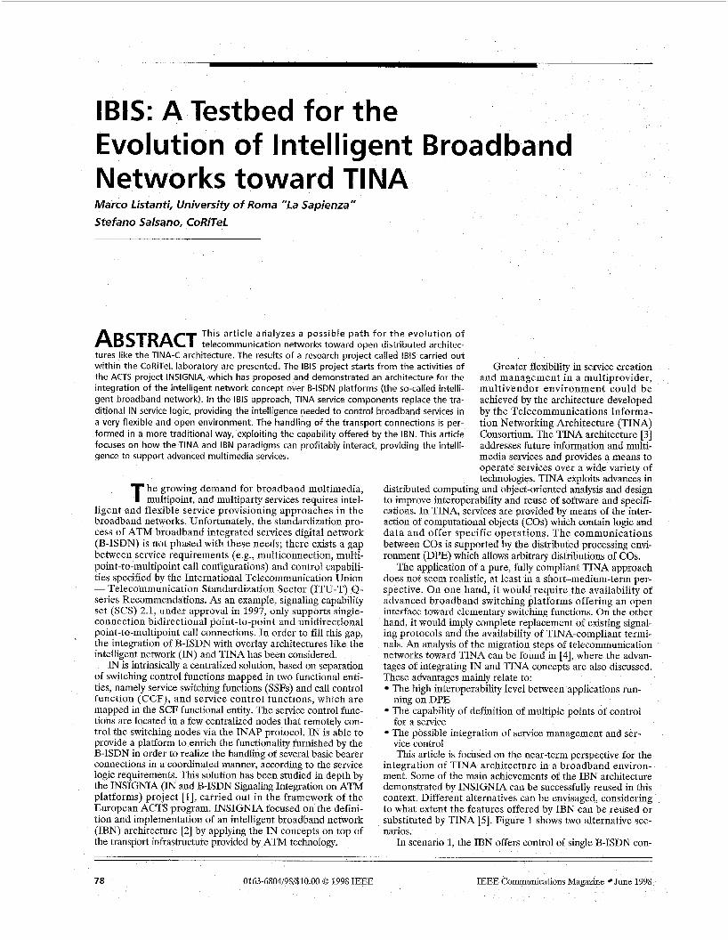
integration of TINA architecture in a broadband environ- ment. Some of the main achievements of the IBN architecture demonstrated by INSIGNIA can be successfully reused in this context. Different alternatives can be envisaged, considering to what extent the features offered by IBN can be reused or substituted by TINA [5]. Figure 1 shows two alternative sce- narios.
In scenario 1, the IBN offers control of single B-ISDN con-
he growing demand for broadband multimedia, T multipoint, and multiparty services requires intel- ligent and flexible service provisioning approaches in the broadband networks. Unfortunately, the standardization pro- cess of ATM broadband integrated services digital network (B-ISDN) is not phased with these needs; there exists a gap between service requirements (e.g., multiconnection, multi- point-to-multipoint call configurations) and control capabili- ties specified by the International Telecommunication Union - Telecommunication Standardization Sector (ITU-T) Q- series Recommendations. As an example, signaling capability set (SCS) 2.1, under approval in 1997, only supports single- connection bidirectional point-to-point and unidirectional point-to-multipoint call connections. In order to fill this gap, the integration of B-ISDN with overlay architectures like the intelligent network (IN) and TINA has been considered.
IN is intrinsically a centralized solution, based on separation of switching control functions mapped in two functional enti- ties, namely service switching functions (SSFs) and call control function (CCF), and service control functions, which are mapped in the SCF functional entity. The service control func- tions are located in a few centralized nodes that remotely con- trol the switching nodes via the I N N protocol. IN is able to provide a platform to enrich the functionality furnished by the B-ISDN in order to realize the handling of several basic bearer connections in a coordinated manner, according to the service logic requirements. This solution has been studied in depth by the INSIGNIA (IN and B-ISDN Signaling Integration on ATM platforms) project [ 11, carried out in the framework of the European ACTS program. INSIGNIA focused on the defini- tion and implementation of an intelligent broadband network (IBN) architecture [2] by applying the IN concepts on top of the transport infrastructure provided by ATM technology.
78 0163-6804/98/$10.00 0 1998 IEEE IEEE Communications Magazine June 1998
nections; the TINA services have to coordinate a set of single point-to-point and/or point-to- multipoint B-ISDN connections to build com- plex service configurations. As in the traditional IN environment, the means to control single connections are given by the basic call state model (BCSM) [6]. The BCSM models the evo- lution of a B-ISDN call and provides triggers for interactions with TINA connection manage- ment objects through a specialized adaptation unit (AU).
A higher-level interface is foreseen in sce- nario 2. Coordination of several connections among a number of parties is performed by the IBN itself using the session model [7]. The ses- sion model allows a pool of B-ISDN connec- tions to be managed by TINA with a single
Scenario 1 pk computational # ? I Scenario2
IBN-TINA interface
node
.... ..-.. IBN-TINA interface
IBN
1 node
. ._ -_ -. -~ ~ _. . I Figure 1. Different scenarios for ZBNITZNA integration.
interaction. It releases TINA from connection management aspects by masking basic connection operations and hiding the BCSM level.
The second scenario should lead to a smoother introduc- tion of TINA due to the inherent simplifications of interac- tions and avoids the need to support DPE in every switching node. Moreover, scenario 2 could possibly allow simple migra- tion from IBN architecture. A detailed architectural model realizing this scenario is dealt with in this article. Field experi- ences arising from the implementation of the above-men- tioned concepts in a laboratory demonstrator called IBIS (Implementation of Integrated IN and B-ISDN Signaling) are described as well.
The main goal of the IBIS project is to realize a testbed to investigate and test advanced control architectures for broad- band multimedia services and, in particular, architectural aspects involved in application of TINA concepts on top of B- ISDN infrastructure. In the IBIS context the IBN architecture (as proposed by the INSIGNIA project) has been assumed as the starting point. IBN has been enriched mainly by introduc- ing point-to-multipoint call handling and the session creation capability needed to realize multisession services. The tradi- tional service logic programs running in the IN SCF are replaced by TINA-compliant COS. In the following this replacement is referred to as “TINArization of the SCF.” A specific AU is defined to allow interworking of the TINA world with the enhanced IBN.
In particular, the main achievements reported in this arti- cle are:
Definition of BCSM for B-ISDN point-to-multipoint calls and enhancement of the model for call unrelated interac- tions Enhancement of the concept of session control by consid- ering the introduction of multiple-session concepts, allowing distribution of a session over multiple IBN nodes Specification and implementation of an AU, allowing interaction between TINA COS and IBN Particularization of the TINA computational model, allowing B-ISDN connection handling Mapping of the TINA service session graph in the IBN session model In the following section the architecture for the evolution
of the IBN toward B-ISDN/TINA as implemented in the IBIS testbed is presented. The section after that is focused on a specific description of IBN functionality enhancement for interaction with the TINA environment. TINArization of SCFs is dealt with next. Two aspects are mainly discussed: the TINA computational model and the interworking functionali- ty for the interaction with the IBN environment. Finally, as a
case study, the provision of broadband videoconference (B- VC) service via the implemented architecture is discussed.
IBIS CONTROL ARCHITECTURE The IBIS control architecture takes the IBN architecture (as proposed by the INSIGNIA project [l]) as the starting point t o introduce advanced features and exploit the migration toward TINA. A description of the IBN concept and architec- tural elements can be found in [8]. In IBIS, the IBN function- al elements in the session control domain and B-ISDN control domain (e.g., B-SSF, B-CCF) are enriched, mainly by intro- ducing the capability to handle point-to-multipoint calls and create sessions in the SCF-SSF direction, as needed to realize multisession services. Within the service control domain, the traditional service logic programs running in the B-SCF will be replaced by TINA-compliant COS. The TINA service architecture is fully exploited for the realization of the service logic, while the handling of connections is performed by means of the IN capabilities of the IBN. A specific AU is defined to allow interworking of the TINA world with IBN.
Unlike in the traditional IN, where an instance of a service logic program (SLP) is invoked in the B-SCP to control a spe- cific service instance, in the IBIS architecture the B-SCF per- forms the interworking between the IBN and TINA architectures. The service logic is performed by a set of TINA COS. Nevertheless, in the scenario shown in Fig. 2 the B-SCF can offer an external behavior which is fully compatible with traditional IN architecture.
According to the IBN architecture, the main task of the B- SSF function is to manage the session model [7]. The B-SSF performs the mapping of session-related operations into call- level operation and vice versa. The B-SSF has been enhanced in the IBIS architecture to support point-to-multipoint calls, SCP-initiated setup of a call-unrelated association, and cre- ation of a session initiated by the B-SCF. A session within the B-SSF can handle an arbitrary combination of basic calls, point-to-multipoint calls, and call-unrelated associations.
The B-CCF and broadband call-unrelated service function (B-CUSF) allow interaction of the IN with the B-ISDN con- trol and signaling function. The BCSM and basic call-unrelat- ed state model (BCUSM) allow the service logic to control the B-ISDN calls and call-unrelated associations, respectively. In the context of IBIS, the call modeling has been enhanced to support point-to-multipoint calls and SCP-initiated call- unrelated associations.
In the IBIS architecture, a service can span multiple ses- sions in different B-SSPs. The service logic in the B-SCP is able to create a new session in a B-SSP which is not already involved in a service. Therefore, it is a task of the B-SCF to
IEEE Communications Magazine June 1998 79
Figure 2. The IBIS architectural model,
TINA Service architecture computational objects
SCF/TlNA adaDtatron unit / \ \
B-IN
(0
- .. ._ - Figure 3. IBNITINA interworking.
correlate the different sessions and maintain the overall view of the service. The TINA part of the architecture will accom- plish this task.
In order to “TINArize” the B-SCF, a set of TINA COS and their interaction to provide the different multimedia ser- vices must be defined. Interworking of TINA service architec- ture with IBN functional entities is realized by means of an interworking object (IwO) in the SCFITINA AU. Figure 3 highlights the proposed IBN/TINA interworking.
The B-INAP protocol defined for the IBN architecture can be used on the B-SSFB-SCF interface. B-INAP provides the means to set up and release connections between end users and to establish communication between the user and the ser- vice logic. The user terminals and switching ATM platforms will not change the way they interact with the service logic with respect to the IBN. As a matter of fact, in the proposed scenario there are no TINA-compliant end users and no TINA applications running on user terminals. The user equip- ment is the same as that used in the IBN [9].
The role of the IwO within the AU is to realize the map-
ping between the B - I N N information flows and the methods defined in the TINA COS’ interfaces. For example, when a user requests a service, the B-SSF sends a B - I N N operation to the B-SCF. Within the TINA service logic as a conse- quence of this message, the set of COS needed to provide the required service will be instantiated and configured. On the other hand, when TINA service logic needs to set up a con- nection, the AU will translate this request into one or more B-INAP operations. Since a single service instance can span several B-SSPs, coordination of the different sessions is per- formed by the TINA service logic. The TINA service session graph (SSG) is used to keep the overall information about the state of a service: the involved users, the network resources, and thek relationships.
BROADBAND CALL CONTROL FUNCTION AND SERVICE SWITCHING FUNCTION EVOLUTION
In this section an evolution of the IBN with respect to the outcome of the INSIGNIA project is proposed. The enhance- ments concern the B-SSF, B-CCF, and B-CUSF functional entities, which belong to the session control domain and the B- ISDN control domain. In the context of the IBIS architecture, the TINA-based service logic complements this evolution in the service control domain. It is worth noting that the enhance- ments proposed in this section could also be applied to a clas- sical IBN without any TINA involvement.
POI NT-TO-M U LTI POINT CALL MODELING A point-to-multipoint calllconnection allows distribution of a unidirectional flow of data from one source, the root party, to a set of sinks, the leaf parties. The basic point-to-multipoint call is specified by ITU-T Recommendation Q.2971 [lo] at the user-network interface (UNI) and Q.2722.1 [ll] at the net- work-node interface (“1). A point-to-multipoint call is initi- ated by the root by sending a SETUP message which explicitly requests the point-to-multipoint configuration. The root party can send ADD PARTY messages to add further leaves and DROP PARTY messages to remove parties from the call. A
80 IEEE Communications Magazine June 1998
I First leaf I
leaf party can drop itself from a call, but cannot join itself t o a point-to- multipoint call. The call can be explic- itly torn down by the root by sending a RELEASE message, which releases all the leaves.
The first requirement for an IN call model for a point-to-multipoint call is to allow monitoring and control of the
I CCM: Call control manager PCM: Party control manager
Figure 4. BCSMinstances for the control
I
I..- __ .- .- .A of a point-to-multipoint call. . -
events in a basic point-to-multipoint call (i.e., initiated by the root using UN1 signaling), such as call setup, party addition, party answer, call release, and party release. Following the IBN approach for SCP-initiated operation, the additional require- ments for call modeling are to support SCP-initiated party addition (addition of parties to an already established point- to-multipoint call on behalf of the service logic) and SCP-initi- ated ZNpoint-to-multipoint call setup (establishment of a point-to-multipoint configuration on behalf of the service logic). Moreover, it must be considered that in a point-to-mul- tipoint call there is a set of parties which can evolve indepen- dently, making it infeasible to control them within a single state machine.
The available IN standards describe the call model for a point-to-point call with a single connection, as suitable for plain old telephone service (POTS) and narrowband ISDN (N-ISDN). The INSIGNIA project has defined a BCSM suit- able for IBN based on this classical BCSM. The proposed solution foresees reusing the BCSM defined in the IBN archi- tecture, which will be called the call control manager (CCM) hereafter, and adding a state machine representing each leaf party, called the party control manager (PCM). Considering the setup of a traditional point-to-multipoint call (i.e., set up by the root), when the setup indication is received by the B- CCF, a PCM is instantiated and will evolve in parallel with the CCM, which is instantiated as in the point-to-point case. The CCM represents the call state, while the PCM represents the state of the first leaf party. The leaf parties that will be successively connected are monitored by new instances of the PCM, as shown in Fig. 4.
A complete description of the points in call (PICs) and detection points (DPs) defined in the CCM and PCM is beyond the scope of this figure [12]. The DP in the PCM can be armed according to the service logic requirements. As an example, the Add Party Attempt DP is encountered when the root sends an ADD PARTY message. If it is necessary to monitor each addition of a new party to allow an IN-based access control service or accounting service, this DP will be
armed to report each attempt. The DPs in the PCM can be armed inde- pendently for each leaf according to service requirements. The DPs in the CCM allow monitoring of the state of the whole call: for example, the Call Released DP, if armed, can detect the release of the whole call requested by the root Dartv.
The ihrdduction of SCP-initiated party adding and point-to-multipoint
call setup is realized by means of extension to the CCF inside the nodes, with no impact on signaling. For the SCP-initiated adding of parties, the CCF has to be modified to receive a request from the B-SSF to add a new party and to control the signaling toward the leaf party on the outgoing UN1 or NNI link. The adding of these parties will not be communicated to the root at the signaling level because the Q.2971 procedures do not allow it. The same approach is applied for SCP-initiat- ed point-to-multipoint call setup. Since a node cannot set up a point-to-multipoint call toward a root party, a point-to-point call is established to support a unidirectional connection from the root to the node; then an independent (with respect to B- ISDN signaling) point-to-multipoint call toward the leaf par- ties is set up. The two phases for the setup of an IN-initiated point-to-multipoint call are depicted in Fig. 5. The setup of an additional leaf party is also shown. The dotted arrows show the control plane relationships (the direction represents the party who receives the setup), while the thick arrows show the user plane links (the direction represents the flow of data).
The modified CCF will correlate the signaling messages, dialog with service logic, and control the through-connection of the user plane links. As far as the BCSM modeling is con- cerned, the parties that are added on behalf of the service logic will be modeled by instances of the PCM: the service logic can control the result of the party setup, monitor the release of the parties, and so on. The CCM represents only the status of the root party (e.g., notifying a release coming from the root).
As far as the session model enhancements are concerned, the bearer connection object will be extended to support a set of more than two legs. A new attribute, configuration, is added to the bearer connection object with possible values point-to-point and point-to-multipoint. The leg objects will rep- resent the root and set of leaves that compose a point-to- multipoint call.
The new flows that must be added to the set of B-SSF/B- SCF information flows are reported in the first two rows of
I I (,,,] I
Point-to-point setup
I Root U I
BCSM modeling
Point-to-
[y&-q Point-to-multi Doint
0 Root 0
I
0 , I Leaf 2 '
Root
I First phase: setup of the link Second phase: setu of the link Setup of the link toward an additional leaf party toward the root party toward a IeaPparty
I .- -_ - -. - - - - - - -- --
Figure 5. Setup of a SCP initiatedpoint-to-multipoint call.
IEEE Communications Magazine June 1998 81
usage of net\\ 01 k i csourccs. 111 this solution the sessions in each B-SSP represent only a partial view of the -I I_--- ~ ~
Gcneric Functional Protocol Add party and servicc configuration hltrging of these paitinl w" is peiforined by
Multiple session 1 Create session - --
Table 1. Newly defined B-SSFIB-SCF information flows.
Table 1. The Add point-to-multipoint bearer info flow allows the service logic to establish a SCP-initiated point-to-multi- point call provided the root party and the list of leaf parties are connected. A bearer connection object will be created with the configuration attribute set to point-to-multipoint, a party object will be created for each party that does not still exist in the session, and one leg object for each party will be created to represent the link with the bearer connection. The Join parties to point-to-multipoint bearer info flow allows the service logic to add a set of new leaf parties to a point-to-mul- tipoint (either root-initiated or SCP-initiated) call. An existing bearer connection object is provided in the message, while the same rules for creating party and leg objects apply as for the Add point-to-multipoint bearer info flow.
GENERIC FUNCTIONAL PROTOCOL MODELING The out-channel call-unrelated interaction allows direct exchange of service information between the user terminal and service logic. At the UN1 of the B-ISDN the information is exchanged via a connection-oriented bearer-independent (COBI) signaling association, as defined in the Generic Func- tional Protocol [13]. A similar feature is already included in the IN Capability Set 2 Recommendations [6], where it is called user service interaction (USI). The US1 can comple- ment the traditional in-band user interaction via the B-IP, which in the narrowband IN allows the service logic to send voice messages and collect DTMF tones. The US1 mechanism is more efficient than traditional in-band interaction and is especially suitable if the terminal equipment is "smart" as in a broadband context. In the IBN architecture, simple support is provided for this mechanism. Only the user can initiate a COBI association to send some service information, as used for registration procedures in a virtual private network.
In the IBIS context, the SCP can initiate a COBI associa- tion toward any user and can use this association to convey any information (e.g., an invitation to take part in a ser- vice). The COBI association will last as long as the user ser- vice communication is needed. No specific enhancements to the static session model are needed to support the SCP-ini- tiated call-unrelated association, while the dynamic behavior is extended and the Join party and bearer unrelated connec- tion has been added (Table 1). This info flow allows the ser- vice logic to establish a COBI association toward a given end user.
SUPPORT OF MULTIPLE SESSIONS In the IBN architecture, for a single service instance a single session comprises all the B-ISDN connections involved in the service. This means that a single B-SSP node controls the whole set of B-ISDN connections. This solution gives rise to inefficient resource utilization, especially in multiparty ser- vices. The problem is that a connection between two remote users must always be routed through the controlling B-SSP node.
A more efficient solution allows more than one session to be involved in a service instance. This means that the connec- tions composing the service configuration are controlled by different B-SSPs. The B-SSPs can be selected to minimize
the TINA service logic, as will bk described later. At the B-SSF level a new capability needs to be intro- duced to let the service logic acti-
vate a session in the B-SCF+B-SSF direction. The Create Session info flow allows the service logic to start a new IN ses- sion in a B-SSP that is not already involved in the service instance (Table 1).
TINA SERVICE LOGIC FUNCTIONALITY The scope of this section is the description of the TINA ser- vice architecture for IBIS and its interaction with the IBN. A TINA-based computational model is proposed; then attention is focused on the intenvorking object (IwO), which is the core of the IBN/TINA interaction.
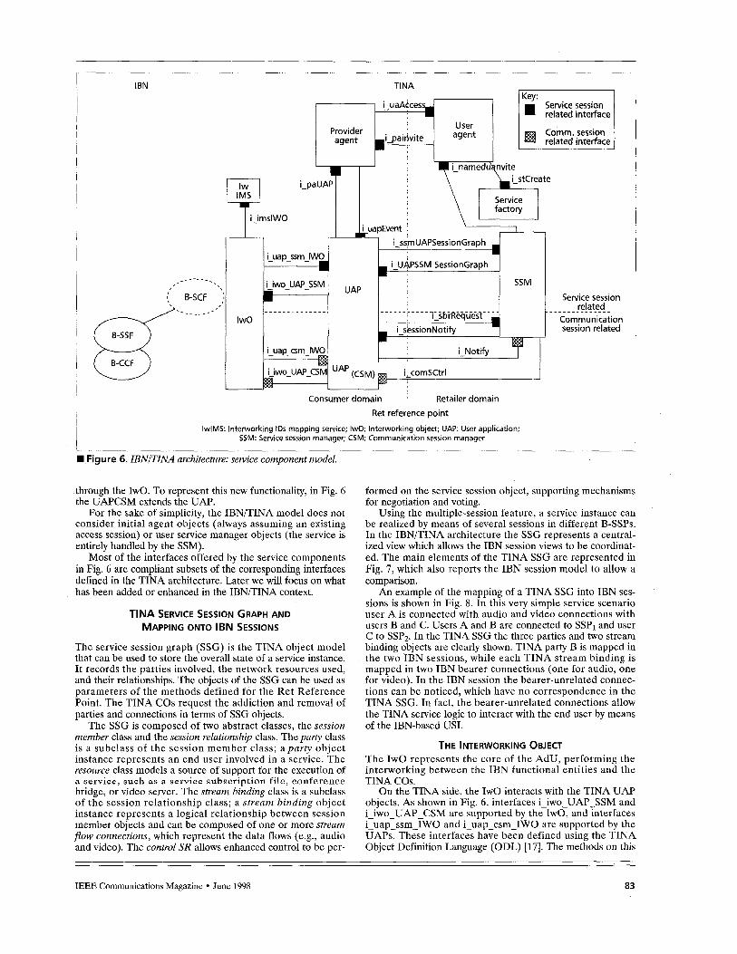
THE TINA-BASED COMPUTATIONAL MODEL The TINA-based computational model of the IBN-TINA architecture is reported in Fig. 6, which shows the service components and their interfaces and relationships. A practical example will be shown later in Fig. 10. The TINA COS replace the traditional IN service logic. A basic assumption is that each end user is represented in the SCFIAU with its own "consumer domain" objects. On the IN side the consumer domain objects interacts with an TWO, which is the core of the AU, whereas on the TINA side they interact with the "retailer domain" objects. Specification of the IwO is one of the results of the IBIS project. On the TINA side, the specifications of the interface between consumer and provider, called Ret Refer- ence Point [14], have been followed and only slightly enhanced when needed. In a fully TINA-compliant architecture, the user-plane connections are provided by the TINA communi- cation management architecture (CMA), which is a part of the network resource architecture (NRA) [15]. In the IBN/TINA architecture the service architecture objects will interact with the IwO within the B-SCF to request setup of the user plane connections to the IBN entities.
In the classical TINA service architecture [16] the user application (UAP) objects model the different applications in the consumer domain. The user agent (UA) objects represent the end user in the retailer domain. The provider agent (PA) represents the provider in the consumer domain and interacts with the UAs to allow the user to take part in service sessions. In the retailer domain the service session manager (SSM) is responsible for control of the service session. The SSM logi- cally manages the resources needed to provide the service, stores the overall state, and requests actual resources of the communication session objects. The service factory (SF) cre- ates the service session components for a service type.
In the proposed IBNITINA architecture the main features of the TINA objects have been implemented. The logic to implement a given service can be split among the UAP and the SSM. The UAP plays a key role because it can store the user-specific information with respect to a given service. For example, in the videoconference service that will be described later, the UAP of the user requesting the service stores the set of conferees to invite, the characteristics of the connections, and so on, and makes the cor g requests of the SSM. A new functionality has been to the UAP: the UAP will support connection man handling the requests coming from the SSM and interacting with the IBN world
82 IEEE Communications Magazine June 1998
I
I
I
i i I I
i I
!
I
i
I I
1 I
IBN TINA
I
I I ! !
i
Service session
Communication ,
session related :
_ _ - -- - _
i I
I
6-SCF ) - - _ . _ _ _ - *
Consumer domain ' Retailer domain
Ret reference point
IwlMS: lnterworking IDS mapping service; IwO: lnterworking object; UAP: User application; SSM: Service session manager; CSM: Communication session manager
~. - - - W Figure 6. IBNITINA architecture: service component model.
through the IwO. To represent this new functionality, in Fig. 6 the UAPCSM extends the UAP.
For the sake of simplicity, the IBN/TINA model does not consider initial agent objects (always assuming an existing access session) or user service manager objects (the service is entirely handled by the SSM).
Most of the interfaces offered by the service components in Fig. 6 are compliant subsets of the corresponding interfaces defined in the TINA architecture. Later we will focus on what has been added or enhanced in the IBNEINA context.
TINA SERVICE SESSION GRAPH AND MAPPING ONTO IBN SESSIONS
The service session graph (SSG) is the TINA object model that can be used to store the overall state of a service instance. It records the parties involved, the network resources used, and their relationships. The objects of the SSG can be used as parameters of the methods defined for the Ret Reference Point. The TINA COS request the addiction and removal of parties and connections in terms of SSG objects.
The SSG is composed of two abstract classes, the session member class and the session relationship class. The party class is a subclass of the session member class; aparty object instance represents an end user involved in a service. The resource class models a source of support for the execution of a service, such as a service subscription file, conference bridge, or video server. The stream binding class is a subclass of the session relationship class; a stream binding object instance represents a logical relationship between session member objects and can be composed of one or more stream flow connections, which represent the data flows (e.g., audio and video). The control SR allows enhanced control to be per-
-
formed on the service session object, supporting mechanisms for negotiation and voting.
Using the multiple-session feature, a service instance can be realized by means of several sessions in different B-SSPs. In the IBN/TINA architecture the SSG represents a central- ized view which allows the IBN session views to be coordinat- ed. The main elements of the TINA SSG are represented in Fig. 7, which also reports the IBN session model to allow a comparison.
An example of the mapping of a TINA SSG into IBN ses- sions is shown in Fig. 8. In this very simple service scenario user A is connected with audio and video connections with users B and C. Users A and B are connected to SSPl and user C to SSP2. In the TINA SSG the three parties and two stream binding objects are clearly shown. TINA party B is mapped in the two IBN sessions, while each TINA stream binding is mapped in two IBN bearer connections (one for audio, one for video). In the IBN session the bearer-unrelated connec- tions can be noticed, which have no correspondence in the TINA SSG. In fact, the bearer-unrelated connections allow the TINA service logic to interact with the end user by means of the IBN-based USI.
THE INTERWORKING OBJECT The IwO represents the core of the AdU, performing the interworking between the IBN functional entities and the TINA COS.
On the TINA side, the IwO interacts with the TINA UAP objects. As shown in Fig. 6, interfaces i-iwo-UAP-SSM and i-iwo-UAP-CSM are supported by the IwO, and interfaces i-uap-ssm-IWO and i-uap-csm-IWO are supported by the UAPs. These interfaces have been defined using the TINA Object Definition Language (ODL) [17]. The methods on this
IEEE Communications Magazine June 1998 83
.
Figure 7. INsession and TINA SSG models.
interface allows the IwO to request actions of the TINA objects on behalf of the real users (e.g., to start a service instance or modify the service configuration) and to report the results of actions performed in the IBN domain. The UAP is able to request the IwO to interact with the real users (using the facilities provided by the IBN) and to set up the required transport connections.
On the IBN side, the IwO will interact with a simplified B- SCF that will handle the dialogue with the B-SSFs, terminat- ing the B-INAP protocol. For the services handled by the TINA service logic, the B-SCF will not make autonomous decisions, relaying all B-INAP messages to the IwO.
In order to perform the mapping between the IBN and TINA paradigms, the IwO must access and/or store some information related to the mapping between elements in the two different domains. For example, the IwO must be able to associate a TINA user ID with an IBN calling party number provided in the B-INAP Service Request message. A specific CO has been defined, called the Interworking IDS Mapping Service (IwIMS), which has been located in the AU (consumer
which in the pure TINA architecture is supported by the com- munication session manager object (CSM) in the network resource architecture, is now supported by the extended UAPs. This interface provides operations to establish flow connections. These operations are mapped by the UAP objects into invocations of suitable methods on the IwO object.
The UAPs are able to interact with the SSM objects to notify them of the state of the connections when alerted by the IwO. The UAF’ emulates the CSM behavior in the interac- tion with the SSM, invoking a method supported by the i-Notify interface.
THE BROADBAND VIDEOCONFERENCE SERVICE IN THE IBIS TESTBED
The IBIS project has realized the proposed architecture in a testbed running on a LAN. This section gives an overview of the architecture of the testbed, describing the equipment and
domain). In a real-world implementa- tion, this CO should belong to the retailer domain. As another example, the IwO has the task of correctly dis- tributing the B-INAP messages to the different sessions in the TINA + IBN direction and to invoke the different TINA UAP objects in the opposite direction. Therefore, for each service instance the IwO will keep track of the composition of the IBN sessions and will store the mapping between TINA users and IBN party objects, as well as the mapping between the TINA stream binding and IBN bearer connections.
SUPPORT OF CONNECTION
BY THE USER APPLICATION OBJECTS
As in the classical TINA architecture, the interface “i-sessionNotify” (Fig. 6) allows the SSM to notify a requester or participant in a stream binding of the state of stream binding operations. The UAP objects are extended to sup- port requests to set up the connec- tions coming from the TINA SSM objects. The interface i-ComSctrl,
ANAGEMENT
I ITINASSG i i ‘ I @Stream
A \-
H Figure 8. Mapping between TINA SSG and INsessions.
84 IEEE Communications Magazine * June 1998
TINA retailer domain COS
DPE (CORBA) based TINA Ret Ref point
NNI interface
\ Not implemented within IBIS
-: DPE (CORBA) based j SSF-SCF interface
Ihternal (SDT-based) g F - S S F interface
.............................. __ ..-. .- -. .~ . Figure 9. Architecture of the testbed implementation.
software tools used. Only the control aspects have been con- sidered in the IBIS testbed. Figure 9 shows the architecture of the testbed implementation.
A broadband videoconference (B-VC) service logic has been defined, using as a guideline the methods and event traces contained in the draft TINA specifications for the TINA Ret Reference Point [14].
On the TINA side, the IONA Technologies OrbixWeb tool which implements the Common Object Request Broker Architecture (CORBA) 2.0 specifications has been used. The OrbixWeb allows Java code to be written to implement the methods defined in a CORBA Interface Definition Language (IDL) interface. In order to implement the TINA service architecture, the object interfaces have been defined using CORBA IDL translating the TINA specifications written in ODL.
On the IBN side, the B-INAP has been implemented according to the INSIGNIA project specifications adding the enhancements described in the previous section. It is worth noting that the B-SSF/B-SCF interface has been realized on a CORBA platform mapping the Abstract Syntax Notation v. 1 (ASN.l) specification into IDL. In particular, each B-INAP message on the B-SSF/B-SCF has been mapped into a specific method in the corresponding CORBA-based interface. The CORBA protocols replace the full SS7 protocol stack that would be used to transport the B-INAP. This solution, which has been adopted mainly for ease of implementation, is inter- esting in a more general context, since the introduction of the distributed platform environment into the existing telecommu- nication network is under consideration by network operators.
The functionality of the B-SSF, B-CCF, and B-CUSF have been described with the Specification and Description Lan- guage (SDL) [18] and implemented using the Telelogic SDT tool. At the UN1 a suitable subset of the Recommendations for point-to-point (Q.2931), point-to-multipoint (Q.2971), and Generic Functional Protocol (Q.2932) has been implemented, also using the SDT tool. The protocol state machines for the user and network sides of UN1 have been realized. These machines send and process the signaling messages on the UN1 and offer a primitive-based interface toward the switch call handling processes (il, Fig. 9). A call handler has been devel- oped within the B-SSP to control a set of UNIs. This call han- dler controls the point-to-point calls, point-to-multipoint calls, and call-unrelated association, and integrates the BCSM and BCUSM functionality to allow the interaction with IBN, act- ing as the B-CCF. An internal interface toward the SSF has been defined (i2). The B-SSF realizes the session model and dialogues with the B-SCF (i3).
The physical grouping of entities is shown by the dashed line in Fig. 9. The B-SSP entities (B-SSF, B-CCF, B-CUSF, and UN1 protocol machine - network side) are grouped in a single application running on a Sparcstation 20. The imple- mentation of the CORBA-based B-SSF interface runs on the same workstation. The TINA COS run on another worksta- tion. A set of standalone applications implement the user ter- minals. These applications run on different workstations; more than one terminal can be mapped in a single worksta- tion. The UN1 messages among these applications and the B- SSP workstation are formatted according to the ITU-T Recommendations and are exchanged using socket interfaces
IEEE Communications Magazine June 1998 85
TINA I
Figure IO. IBNITINA computational model. an example of the architecture.
provided by the UNIX operating system. The internal inter- faces i l and i2 within the B-SSP application are based on the exchange of SDL signals. The i3 and i4 interfaces a re CORBA-based.
A set of GUI applications has been developed in Java to allow basic management operations (i.e., setup of the testbed environment), emulation of terminal operations (service request, call setup), and real-time visualization of messages on
\.--
I I
I
!
I I
I
I
the UNIs and on the internal interfaces within the B-SSP application. These Java applications can run on external workstations or PCs.
A B-VC SERVICE EXAMPLE The computational model used to manage a B- VC service instance involving three users is shown in Fig. 10. Users A and B are connected to the same B-SSP, user C to a different B-SSP. In the TINA service logic, a UA, a provider agent (PA), and a UAP object are instantiated for each user. Each user is represented by a cor- responding UAP in the consumer domain and by a UA that stores the user profile in the retailer domain. In the user profile there is also informa- tion related to the IBN context such as the iden- tifier of the B-SSF to which the user is connected and the IBN number of the terminal at which the user wants to be called.
When a user requests a service in the IBN, the B-INAP Service Request operation is issued from the B-SSF to the B-SCF. The IwO provides for the creation of the corresponding UAP object, and sends it the start-service method. The instantiated UAP stores the information about the videoconference configuration to be realized
and invokes the methods in the SSM as needed to establish and configure the service.
The SSM interacts with the UAPPJM to request the con- nections that physically realize a stream binding, by means of setup-lflowconnection method. The U A P ~ ~ M invokes the add-bearer method in the IwO, which in turn translates it into B-INAP operations (e.g., Add Bearer to Session, Request Report SSM Change).
I UAP: Uter application, PA Provider agrnt; 5 S M Service w w o n managcr, UTSI Usrt-io-service infot mation, ST
gure 1 1. UserA (inviter) invites user C (invitee) to join a service session.
86 IEEE Communications Magazine 0 June 1998
During the active phase of the service, a user is able to invite another user to join in a service session. This scenario is shown in Fig. 11 by means of an event trace. The invited user can accept the invitation and immediately join the service ses- sion. The preconditions for this procedure are:
The invitee user C and inviter user A are connected to dif- ferent SSPs. An IBN session related to the specific service instance is not already instantiated in the B-SSP at which the invitee user is connected. Users A and B are already active in the service.
The main steps to invite a user are: User A sends a message to the TINA service logic by means of the User Service Interaction to invite user C. The IwO invokes the method invite-user in the inviter's UAP. The UAP requests the add party operation of the SSM, using SSG objects as parameters. The TINA service logic contacts the invitee's UA and sends an invitation using the i-nameduahvite interface. The UA forwards the invitation using the iqaInvi te interface of the PA, adding to the parameters the SSF identifier and IBN party number to be called. The PA sends the invitation to the invitee's UAP. The UAP sends a method to the IwO to alert the user by means of the IBN capabilities. The IwO controls the state of the B-SSP at which the invitee is connected. If no session related to the service instance is instantiated, the IwO creates and initializes it, sending the needed B-INAP messages. A COB1 associa- tion toward the invitee is established and allows the invi- tation to be relayed to the user terminal.
CONCLUSIONS This article proposes an approach for the provision of intelli- gence in broadband networks, as needed to support multime- dia service. The approach is based on the evolution of the intelligent broadband network toward an open distributed processing architecture such as TINA. The proposed architec- ture has been implemented in a testbed environment in the framework of the IBIS project. As a first conclusion the IBN, as proposed by the INSIGNIA ACTS project, appears even more interesting because it has been proven to be future- proof. In fact, the largest part of the investment in the deploy- ment of an IBN is probably represented by the B-SSP nodes, which have been successfully reused in a more advanced con- text. The second conclusion concerns the evolution toward TINA. A viable solution such as that proposed here must be found to allow step-by-step introduction of TINA in the telecommunication network starting in the near future.
Further work is required to evaluate the performance of IBNRINA architecture; in fact, the response times for service provisioning could be influenced by the overhead of the dis- tributed orocessing environment supporting TINA. However, the application of the TINA concept is limited to handling the logic of complex services (e.g., videoconference) that could admit a setup time on the order of few seconds. Therefore, it is reasonable that the DPE does not constitute a bottleneck to meet these time requirements.
'
ACKNOWLEDGMENTS
The authors would like to thank all the people who worked in the INSIGNIA project (in particular Michael Geipl, Deutsche Telekom, for his contributions on the TINNINSIGNIA inter- working issues), as well as all the people at CoRiTeL who participated in the IBIS project (especially Rossella Mossotto for her work on the TINA service logic).
REFERENCES [I] A publicly available description of the INSIGNIA project can be found at
http://www.fokus.gmd.de/nthp/insignia/entry.html [21 H. Hussmann and I. Venieris, Eds., Intelligent Broadband Networks,
Wiley, to be published June 1998. [31 Publicly available description of the TINA-C activities and results avail-
able at http://www.tinac.com. [4] U. Herzog and T. Magendaz "Intelligent Networks and TINA - Migration
and Interworking Issues," /nt% Switching Symp., Toronto, Canada, 1997. 151 ACTS INSIGNIA Project deliverable report on topics required from the 1997
Technical Audit, Ch. 2, "lnteroperability between INSIGNIA and TINA." 161 ITU-T Rec. 4.1 224, "Distributed Functional Plane for Intelligent Net-
works CS-2." [7] G. DeZen e t al., "Proposal for an In Switching State Model in an Inte-
grated IN/B-ISDN Scenario," Proc. /S&N '97, May 27-29, 1997, Cernob- bio (Como), Italy.
181 G. Prezerakos et al., "INSIGNIA: A Pan-European trial for the Intelligent Broadband Network Architecture," /€E€ Commun. Mag., this issue.
[91 H. Hussmann et al., "A Transnational IN/B-ISDN Integrated Network for the Provisioning o f Multimedia Services," Proc. ECMAST '97, Milan, Italy, May 21-23, 1997.
[ l o ] ITU-T Rec. 4.2971. "B-ISDN DSSZ - User-Network Interface Layer 3 Specification for Point-to-Multipoint Call/Connection Control."
[I 11 ITU-T Rec. 4.2722.1: "B-ISDN User Part - Network Node Interface Specification for Point-to-Multipoint Call/Connection Control."
[I21 M. Listanti and S. Salsano, "Point-to-Multipoint Call Modelling for the Integration of IN and B-ISDN," Proc. IN '97, Paris, France, Sept. 1997.
[I41 "Ttk Ret Reference Point (v. 1.1) - Response to a Request for Refine- ments and Solutions," draft.
[15] "TINA Network Resource Architecture Version 3.0," Feb. 1997 [I 61 "Service Architecture Version 5.0," TINA-C, June 1997. [17] T/NA Object Definition Language Manual Version 2.3, July 1996 [I81 ITU-T Rec. 2.100. "SDL Methodology Guidelines," Appendices I and 11.
BIOGRAPHIES MARCO LISTANTI [MI ([email protected] .it) received his Dr. Eng. degree in electronics engineering from the Universita d i Roma "La Sapien- za" in 1980. He joined the Fondazione Ugo Bordoni in 1981, where he was leader o f the TLC network architecture group unti l 1991. In November 1991 joined the INFOCOM Dept. of La Sapienza, where he is associate pro- fessor in switching systems. Since 1994, he also collaborates with the Elec- tronic Department of the University of Rome "Tor Vergata" where he holds courses in telecommunication networks. He has participated in several international research projects sponsorized by EEC and ESA and is the author of papers published in the most important technical journals and conferences i n the area o f telecommunication networks. His current research interests focus on ATM networks wi th particular regard to traffic control and signaling aspects. He has represented the Italian PTT adminis- tration in international standardization organizations (ITU, ETSI).
STEFAN0 SALSANO ([email protected]) received his Dr. Ing. degree in electronic engineering from the University of Rome "Tor Vergata" in 1994. Since then he has been with CoRiTeL, a research institute in telecommunications, as a scholarship holder. He has now completed his Ph.D. course at the INFOCOM Department, University of Rome "La Sapienza," and is waiting for the final examination. In 1997 he was employed by CoRiTeL. His research interests include architectures and signaling protocols for broadband networks, focusing on the integration of B-ISDN with IN, and integration of IP and ATM. He has participated in the EC ACTS projects INSIGNIA and ELISA.