IBIS Specification Change Template, Rev. 1.2 BUFFER ISSUE RESOLUTION DOCUMENT (BIRD) BIRD NUMBER: Draft 19 22 7 - – February 25April 21June 310 August 5 , 2015 ISSUE TITLE: Interconnect Modeling Using IBIS-ISS REQUESTOR: Walter Katz, Signal Integrity Software, Inc. DATE SUBMITTED: DATE REVISED: DATE ACCEPTED BY IBIS OPEN FORUM: STATEMENT OF THE ISSUE: This BIRD enhances IBIS with interconnect modeling features to support broadband and coupled package and on-die interconnect using IBIS-ISS and Touchstone data. The BIRD also adds a keyword for buffer rail mapping, to link to the new Terminal definitions defined for buffers. ANALYSIS PATH/DATA THAT LED TO SPECIFICATION: Definitions: Enhanced interconnect descriptions in IBIS, called hereinafter “IBIS Interconnect Models”, rely on several assumptions: 1. IBIS Interconnect Models can be described either using IBIS- ISS subcircuit files or Touchstone files. Interconnect Model definitions may be included inside an IBIS file, but neither IBIS-ISS nor Touchstone data may be included inside an IBIS file. 2. If two points in an IBIS Interconnect Model are “Connected Linked ”, then there is either a low resistance DC electrical path between the two points, or a small insertion loss at the Nyquist frequency between the two points. For 1
Transcript
IBIS Specification Change Template, Rev. 1.2
BUFFER ISSUE RESOLUTION DOCUMENT (BIRD)
BIRD NUMBER: Draft 19227 -– February 25April 21June 310August 5, 2015ISSUE TITLE: Interconnect Modeling Using IBIS-ISSREQUESTOR: Walter Katz, Signal Integrity Software, Inc.
DATE SUBMITTED:DATE REVISED:DATE ACCEPTED BY IBIS OPEN FORUM:
STATEMENT OF THE ISSUE:
This BIRD enhances IBIS with interconnect modeling features to support broadband and coupled package and on-die interconnect using IBIS-ISS and Touchstone data.
The BIRD also adds a keyword for buffer rail mapping, to link to the new Terminal definitions defined for buffers.
ANALYSIS PATH/DATA THAT LED TO SPECIFICATION:
Definitions:
Enhanced interconnect descriptions in IBIS, called hereinafter “IBIS Interconnect Models”, rely on several assumptions:
1. IBIS Interconnect Models can be described either using IBIS-ISS subcircuit files or Touchstone files. Interconnect Model definitions may be included inside an IBIS file, but neither IBIS-ISS nor Touchstone data may be included inside an IBIS file.
[2.] If two points in an IBIS Interconnect Model are “ConnectedLinked”, then there is either a low resistance DC electrical path between the two points, or a small insertion loss at the Nyquist frequency between the two points. For the purposes of IBIS Interconnect Models, “point” and “node” refer to identical locations.
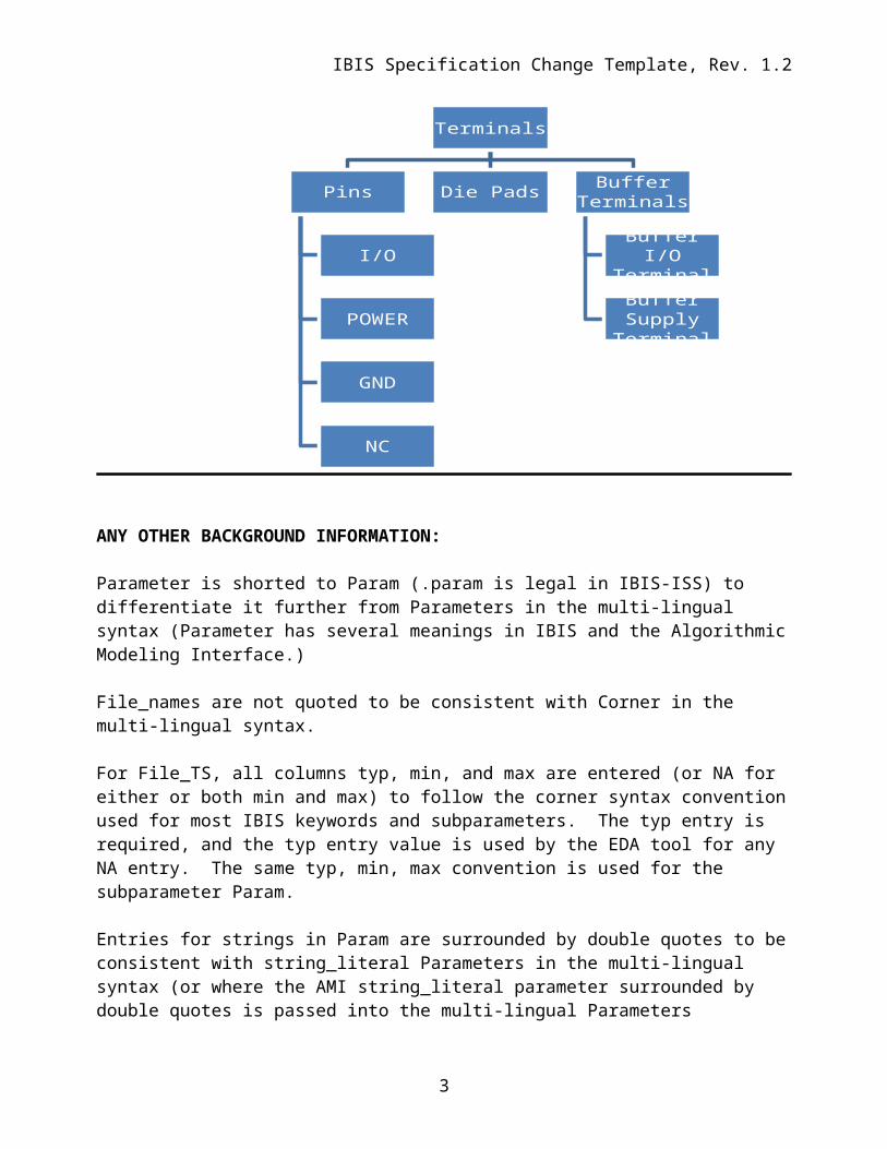
2.[3.] IBIS Components, and therefore IBIS Interconnect Models, contain terminals consisting of Pins, Die Pads, Buffer I/O Terminals, and Buffer Supply Terminals. Pins are defined under the [Pin] keyword, and may be I/O, POWER, GND, or NC.
[4.] For each I/O Pin, there is a single, associated Die Pad and single, associated Buffer I/O Terminal. All of these associated with it that shall be considered are “ConnectedLinked”.
[5.] Under [Pin], for each Signal_name associated with Model_name POWER or GND, all Pins, Die Pads and Buffer Supply Terminals that use that Signal_name are “ConnectedLinked”
[6.] IBIS assumes that each I/O [Pin] is connected to one Die Pad and is one Buffer I/O Terminal. Two differential I/O pins shall be connected to two differential die pads and either two single-ended Buffer I/O Terminals or a single true differential Buffer I/O Terminal.
1
Author, 01/03/-1,
1:1 relationship mentioned for I/Os in items 4 and 6; still missing GND/POWER description. Consider moving this into the main body as definitions section, but defer decision. Need separate chapter, with this as potential introductory section.
Author, 01/03/-1,
A tree diagram, preferably a vertical one, would be very handy here.
Author, 01/03/-1,
Remove the Nyquist reference; refer to all frequencies of interest, small impedance.
Author, 01/03/-1,
We should mention the 1:1 pin to pad assumption here. Are we making that assumption for signal paths only or power/gnd paths also?
IBIS Specification Change Template, Rev. 1.2
3.[7.] If multiple Buffer Terminals (Supply or I/O) are connected to a single pin, EMD shall be used for the interconnect description.
[8.] An Interconnect Model may represent describe the relationship between a single connection between Pins and Buffer Terminals (Supply and or I/O), a signle Pins and linked Die Pads, or between a single Die Pads and a Buffer Terminals (Supply and or I/O). An Interconnect Model may also represent describe multiple connections between multiple Pins and multiple Buffer Terminals (Supply and I/O), multiple Pins and multiple Die Pads, or multiple Die Pads and multiple Buffer Terminals (Supply and I/O).
ANY OTHER BACKGROUND INFORMATION:
Parameter is shorted to Param (.param is legal in IBIS-ISS) to differentiate it further from Parameters in the multi-lingual syntax (Parameter has several meanings in IBIS and the Algorithmic Modeling Interface.)
File_names are not quoted to be consistent with Corner in the multi-lingual syntax.
For File_TS, all columns typ, min, and max are entered (or NA for either or both min and max) to follow the corner syntax convention used for most IBIS keywords and subparameters. The typ entry is required, and the typ entry value is used by the EDA tool for any NA entry. The same typ, min, max convention is used for the subparameter Param.
Entries for strings in Param are surrounded by double quotes to be consistent with string_literal Parameters in the multi-lingual syntax (or where the AMI string_literal parameter surrounded by double quotes is passed into the multi-lingual Parameters reference). The EDA tool needs to convert string_literals into the parameter string syntax in IBIS-ISS.
2
Terminals
Pins
I/O
POWER
GND
NC
Die Pads Buffer Terminals
Buffer I/O Terminal
Buffer Supply Terminal
Author, 01/03/-1,
That may work for numbers, but not so much for file names, which can be arbitrarily(?) long. I would keep all file name syntax the same as far as possible.
Author, 01/03/-1,
Issue is difference in format (syntax), not in concept. Arpad: would prefer a more distinct term than just an abbreviation or variation on an existing name. Bob objects.
Author, 01/03/-1,
Which is this differentiation necessary? Is there a technical reason? Any inconsistency makes it harder on the parser developer, and the model maker too…
Author, 01/03/-1,
Is Circuit Call explicitly excluded, as it does not appear in the diagram? Assumption is yes, but this is an open question. Bob: may be too complicated to combine with Circuit Call/External Circuit. Non-overlap?
Author, 01/03/-1,
Check relationship of “Buffer Supply Terminal” to new “Buffer Rail” concept.
IBIS Specification Change Template, Rev. 1.2
Interaction of Param entries was not discussed. For example, for a transmission line, TD and Z0 could each have max and min entries, but the EDA tool could make available combinations of min/min, min/max, max/min or max/max for any corner . Due to parameter interactions, some mixing of corner combinations might not be realistic. (E.g., Z0min or Z0max might not correlate with TDmin or TDmax values, where TDmin=sqrt(LminCmin), Z0min=sqrt(Lmin/Cmax), etc.).How corners of File_ISSFile_IBIS-ISS and Params are processed might be based on vendor supplied documentation. For example some, but not all, combinations are shown below:
1. One file_name for all corners, one .subckt name, and all corner settings controlled by Param settings
2. One file_name, three .subckts (with internal default .param settings), additional corner settings controlled by Param settings or Param is not used
3. Three file_names with the same .subckt name, but with distinct default .param settings, additional settings controlled by Param settings or Param is not used
4. Three file_names with three distinct .subckt name and with distinct default .param settings, additional corner settings controlled by Param settings or Param is not used
No interpretation is given for Param typ, min, and max values. It is possible to independently use typ, min, or max values for any of the Param names that have been defined (e.g., the max value of one parameter may be used with the min value of another parameter).
3
Author, 01/03/-1,
This contradicts your Z0 TD discussion/example above. There are parameters which are independent, but there are parameters which are strongly related. We need to find a way to mark them somehow. But that’s not easy either…
IBIS Specification Change Template, Rev. 1.2
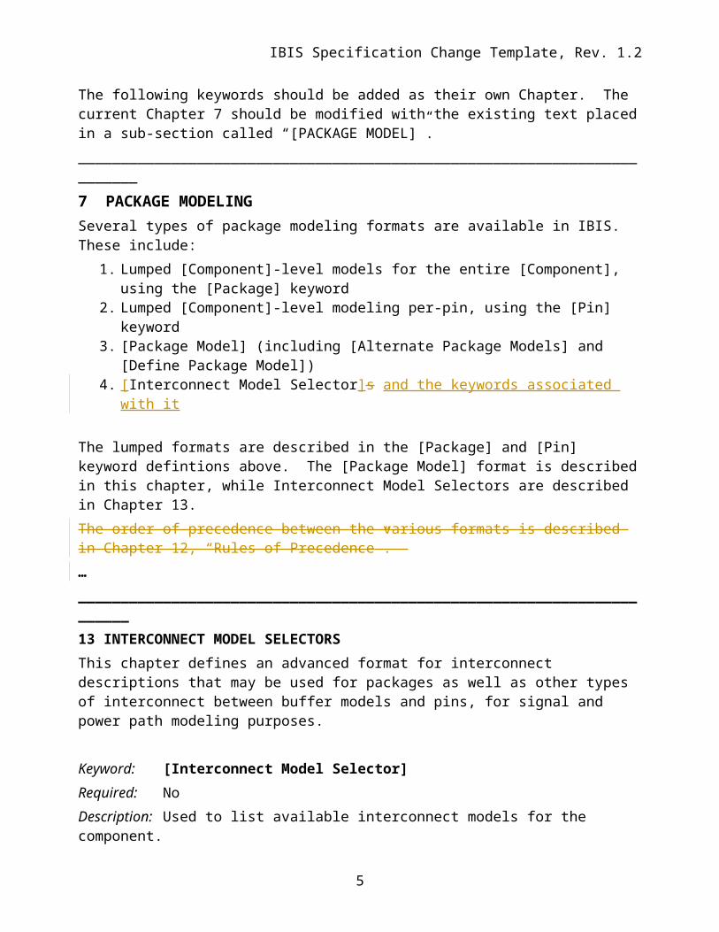
The following keywords should be added as their own Chapter. The current Chapter 7 should be modified with the existing text placed in a sub-section called “[PACKAGE MODEL]”._________________________________________________________________________7 PACKAGE MODELINGSeveral types of package modeling formats are available in IBIS. These include:
1. Lumped [Component]-level models for the entire [Component], using the [Package] keyword
2. Lumped [Component]-level modeling per-pin, using the [Pin] keyword3. [Package Model] (including [Alternate Package Models] and [Define Package Model])[4.] [ Interconnect Model Selector]s and the keywords associated with it
The lumped formats are described in the [Package] and [Pin] keyword defintions above. The [Package Model] format is described in this chapter, while Interconnect Model Selectors are described in Chapter 13.The order of precedence between the various formats is described in Chapter 12, “Rules of Precedence”. …________________________________________________________________________13 INTERCONNECT MODEL SELECTORSThis chapter defines an advanced format for interconnect descriptions that may be used for packages as well as other types of interconnect between buffer models and pins, for signal and power path modeling purposes.
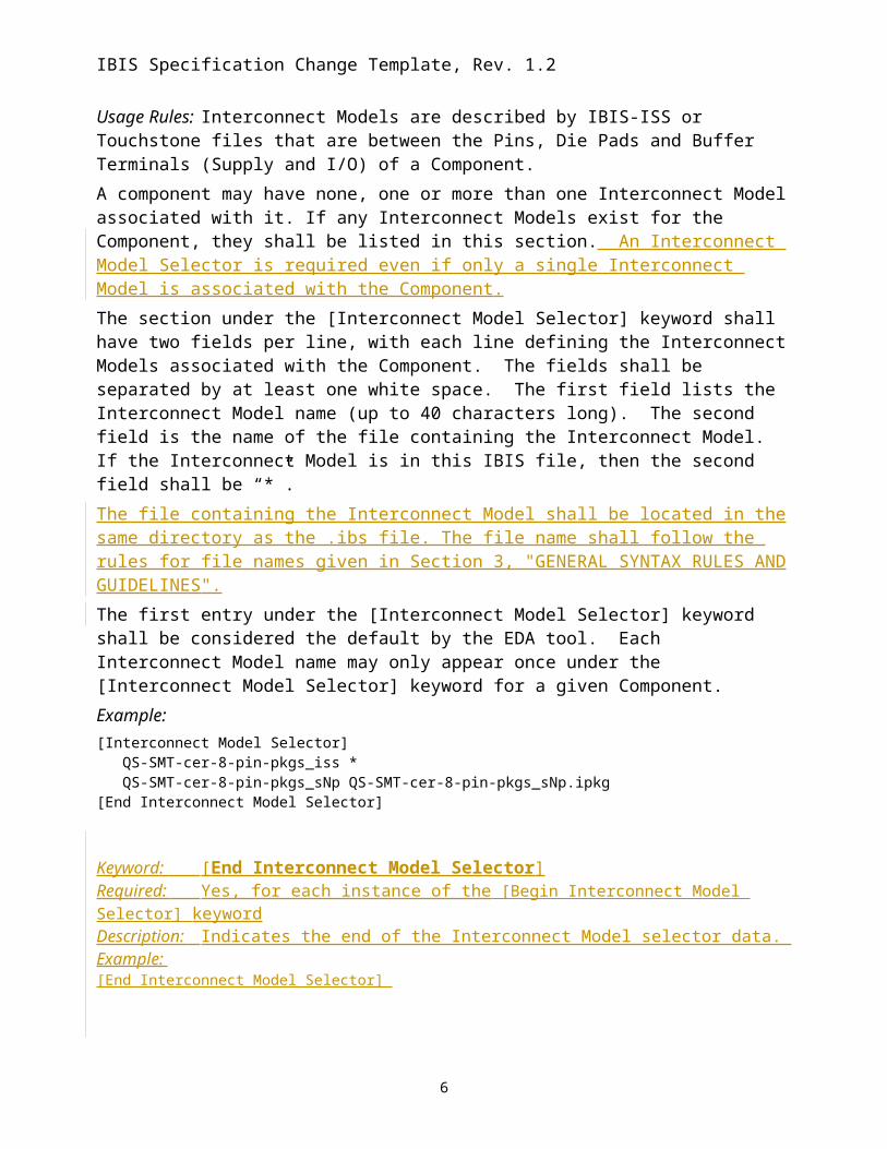
Keyword: [Interconnect Model Selector]Required: NoDescription: Used to list available interconnect models for the component.Usage Rules: Interconnect Models are described by IBIS-ISS or Touchstone files that are between the Pins, Die Pads and Buffer Terminals (Supply and I/O) of a Component.A component may have none, one or more than one Interconnect Model associated with it. If any Interconnect Models exist for the Component, they shall be listed in this section. An Interconnect Model Selector is required even if only a single Interconnect Model is associated with the Component. The section under the [Interconnect Model Selector] keyword shall have two fields per line, with each line defining the Interconnect Models associated with the Component. The fields shall be separated by at least one white space. The first field lists the Interconnect Model name (up to 40 characters long). The second field is the name of the file containing the Interconnect Model. If the Interconnect Model is in this IBIS file, then the second field shall be “*”. The file containing the Interconnect Model shall be located in the same directory as the .ibs file. The file name shall follow the rules for file names given in Section 3, "GENERAL SYNTAX RULES AND GUIDELINES".
4
Author, 01/03/-1,
Bob: specify lower case vs. upper case option/requirements.
Author, 01/03/-1,
The Interconnect Model may be provided in-line within the IBIS file as well; is this clear? Only mentioned with * above.
Author, 01/03/-1,
Is only one [Interconnect Model Selector] permitted under a given Component?
Author, 01/03/-1,
Bob: are separate files clearly supported? Does this cover that situation?
Author, 01/03/-1,
Additional introduction needed here to explain selector vs. Interconnect Model concept. Bob: tree diagram could be added here. What is the coverage? All the pins?
Author, 01/03/-1,
Bob: differential thresholds override single-ended thresholds; this could be a very long BIRD. Remove this sentence. Precedence rules for packages should be repeated in locations where needed.
Author, 01/03/-1,
Per Bob, “model” is overused.
IBIS Specification Change Template, Rev. 1.2
The first entry under the [Interconnect Model Selector] keyword shall be considered the default by the EDA tool. Each Interconnect Model name may only appear once under the [Interconnect Model Selector] keyword for a given Component.Example:[Interconnect Model Selector] QS-SMT-cer-8-pin-pkgs_iss * QS-SMT-cer-8-pin-pkgs_sNp QS-SMT-cer-8-pin-pkgs_sNp.ipkg[End Interconnect Model Selector]
Keyword: [End Interconnect Model Selector]Required: Yes, for each instance of the [Begin Interconnect Model Selector] keywordDescription: Indicates the end of the Interconnect Model selector data. Example: [End Interconnect Model Selector]
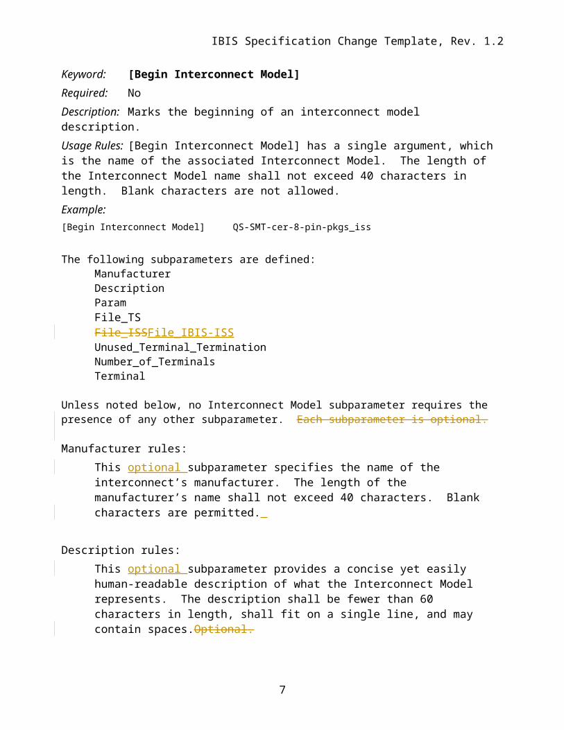
Keyword: [Begin Interconnect Model]Required: NoDescription: Marks the beginning of an interconnect model description.Usage Rules: [Begin Interconnect Model] has a single argument, which is the name of the associated Interconnect Model. The length of the Interconnect Model name shall not exceed 40 characters in length. Blank characters are not allowed. Example:[Begin Interconnect Model] QS-SMT-cer-8-pin-pkgs_iss
The following subparameters are defined:ManufacturerDescriptionParamFile_TSFile_ISSFile_IBIS-ISSUnused_Terminal_TerminationNumber_of_TerminalsTerminal
Unless noted below, no Interconnect Model subparameter requires the presence of any other subparameter. Each subparameter is optional.
Manufacturer rules:This optional subparameter specifies the name of the interconnect’s manufacturer. The length of the manufacturer’s name shall not exceed 40 characters. Blank characters are permitted.
Description rules:
5
Author, 01/03/-1,
Radek: Check for consistency with earlier package formats. Bob: May be different for stand-alone files.
Author, 01/03/-1,
… aside from File_TS and File_IBIS-ISS, and Terminal. Number_of_Terminals? Remove this line.
Author, 01/03/-1,
Bob: should be followed by an “=” to match convention elsewhere in IBIS for assignment of numeric values. Placement of Terminal is dependent on Number_of_Terminals
Author, 01/03/-1,
Required, and must be positioned above Terminal. Should have an “=”?
Author, 01/03/-1,
Bob: requires “=” for assignment of numerical value.
Author, 01/03/-1,
Need Copyright, and other header information if this is not inline; copy from PKG format.
Author, 01/03/-1,
Arpad-Is this 4-letter extension legal per our file-naming rules?
Author, 01/03/-1,
Bob: Should be “s8p” in this instance, for the *filename*, consistent with IBIS references to files/filenames.
Author, 01/03/-1,
Should be lower-case. There may be inconsistency between IBIS and AMI.
IBIS Specification Change Template, Rev. 1.2
This optional subparameter provides a concise yet easily human-readable description of what the Interconnect Model represents. The description shall be fewer than 60 characters in length, shall fit on a single line, and may contain spaces.Optional.
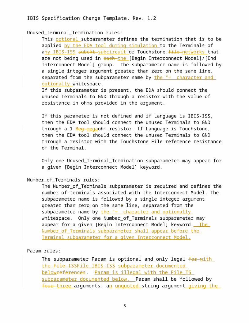
Unused_Terminal_Termination rules:This optional subparameter defines the termination that is to be applied by the EDA tool during simulation to the Terminals of any IBIS-ISS subckt subcircuit or Touchstone file networks that are not being used in each the [Begin Interconnect Model]/[End Interconnect Model] group. The subparameter name is followed by a single integer argument greater than zero on the same line, separated from the subparameter name by the “=” character and optionally whitespace.If this subparameter is present, the EDA should connect the unused Terminals to GND through a resistor with the value of resistance in ohms provided in the argument. If this parameter is not defined and if Language is IBIS-ISS, then the EDA tool should connect the unused Terminals to GND through a 1 Meg megaohm resistor. If Language is Touchstone, then the EDA tool should connect the unused Terminals to GND through a resistor with the Touchstone File reference resistance of the Terminal.
Only one Unused_Terminal_Termination subparameter may appear for a given [Begin Interconnect Model] keyword.
Number_of_Terminals rules: The Number_of_Terminals subparameter is required and defines the number of terminals associated with the Interconnect Model. The subparameter name is followed by a single integer argument greater than zero on the same line, separated from the subparameter name by the “=” character and optionally whitespace. Only one Number_of_Terminals subparameter may appear for a given [Begin Interconnect Model] keyword. The Number_of_Terminals subparameter shall appear before the Terminal subparameter for a given Interconnect Model.
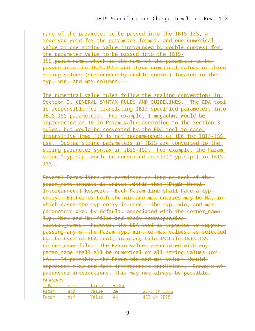
Param rules:The subparameter Param is optional and only legal for with the File_ISSFile_IBIS-ISS subparameter documented belowreferences. Param is illegal with the File_TS subparameter documented below. Param shall be followed by four three arguments: an unquoted string argument giving the name of the parameter to be passed into the IBIS-ISS, a reserved word for the parameter format, and one numerical value or one string value (surrounded by double quotes) for the parameter value to be passed into the IBIS-ISS.param_name, which is the name of the parameter to be passed into the IBIS-ISS; and three numerical values or three string values (surrounded by double quotes) located in the typ, min, and max columns.
The numerical value rules follow the scaling conventions in Section 3, GENERAL SYNTAX RULES AND GUIDELINES. The EDA tool is responsible for translating IBIS specified parameters into IBIS-ISS parameters. For example, 1 megaohm, would be represented as 1M in Param value according to The Section 3 rules, but would be converted by the EDA tool to case-insensitive 1meg (1X is not recommended) or 1E6 for IBIS-ISS use. Quoted string parameters in IBIS are converted to the string parameter syntax in IBIS-ISS. For example, the Param value "typ.s2p" would be converted to str('typ.s2p') in IBIS-ISS.
6
Author, 01/03/-1,
Placement is after Manufacturer but before Terminal.
Author, 01/03/-1,
See = comment above.
Author, 01/03/-1,
Bob: would like this to be open to larger values; “1 megaohm or larger”, to avoid precluding 1 gigaohm.
Author, 01/03/-1,
Bob: clarify that = is required and whitespace is optional; whitespace *may* surround the =.
Author, 01/03/-1,
Radek: Check for consistency with earlier package formats. Bob: May be different for stand-alone files.
IBIS Specification Change Template, Rev. 1.2
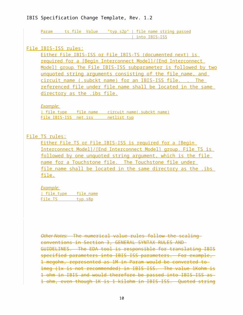
Several Param lines are permitted as long as each of the param_name entries is unique within that [Begin Model Interconnect] keyword. Each Param line shall have a typ entry. Either or both the min and max entries may be NA, in which cases the typ entry is used. The typ, min, and max parameters are, by default, associated with the corner_name Typ, Min, and Max files and their corresponding circuit_names. However, the EDA tool is expected to support passing any of the Param typ, min, or max values, as selected by the User or EDA tool, into any File_ISSFile_IBIS-ISS corner_name file. The Param values associated with any param_name shall all be numerical or all string values (or NA). If possible, the Param min and max values should represent slow and fast interconnect conditions. Because of parameter interactions, this may not always be possible.Examples: | Param name format valueParam abc Value 2m | 2E-3 in IBISParam def Value 4k | 4E3 in IBIS Param ts_file Value "typ_s2p" | file name string passed | into IBIS-ISS
File_IBIS-ISS rules:Either File_IBIS-ISS or File_IBIS-TS (documented next) is required for a [Begin Interconnect Model]/[End Interconnect Model] group. The File_IBIS-ISS subparameter is followed by two unquoted string arguments consisting of the file_name, and circuit_name (.subckt name) for an IBIS-ISS file. . The referenced file under file_name shall be located in the same directory as the .ibs file.
File_TS rules:Either File_TS or File_IBIS-ISS is required for a [Begin Interconnect Model]/[End Interconnect Model] group. File_TS is followed by one unquoted string argument, which is the file name for a Touchstone file. The Touchstone file under file_name shall be located in the same directory as the .ibs file.
Example: | file_type file_nameFile_TS typ.s8p
Other Notes: The numerical value rules follow the scaling conventions in Section 3, GENERAL SYNTAX RULES AND GUIDELINES. The EDA tool is responsible for translating IBIS specified parameters into IBIS-ISS parameters. For example, 1 megohm, represented as 1M in Param would be converted to 1meg (1x is not recommended) in IBIS-ISS. The value 1Kohm is 1 ohm in IBIS and would therefore be passed into IBIS-ISS as 1
7
Author, 01/03/-1,
I would use different words. Saying “1Kohm is” makes it sound like that IBIS-ISS doesn’t understand “1kOhm” or “1kohm”, which I believe it does because it is case insensitive.I wouldl also watch out for spelling, there are no such things as kilohm or megohm, as far as I can tell and I would encourage proper spelling of the scaling factors by recommending the correct cases in the discussion and exaples.
Author, 01/03/-1,
Arpad: remove this sentence, as justification should not be required. Bob: just remove justification but retain rule.
Author, 01/03/-1,
I would copy the [External ***] parameter syntax here too. W ewill have to be careful about establishing “local rues” here for typ/min/max. It is not a good practice to have different rules on that for each keyword…
IBIS Specification Change Template, Rev. 1.2
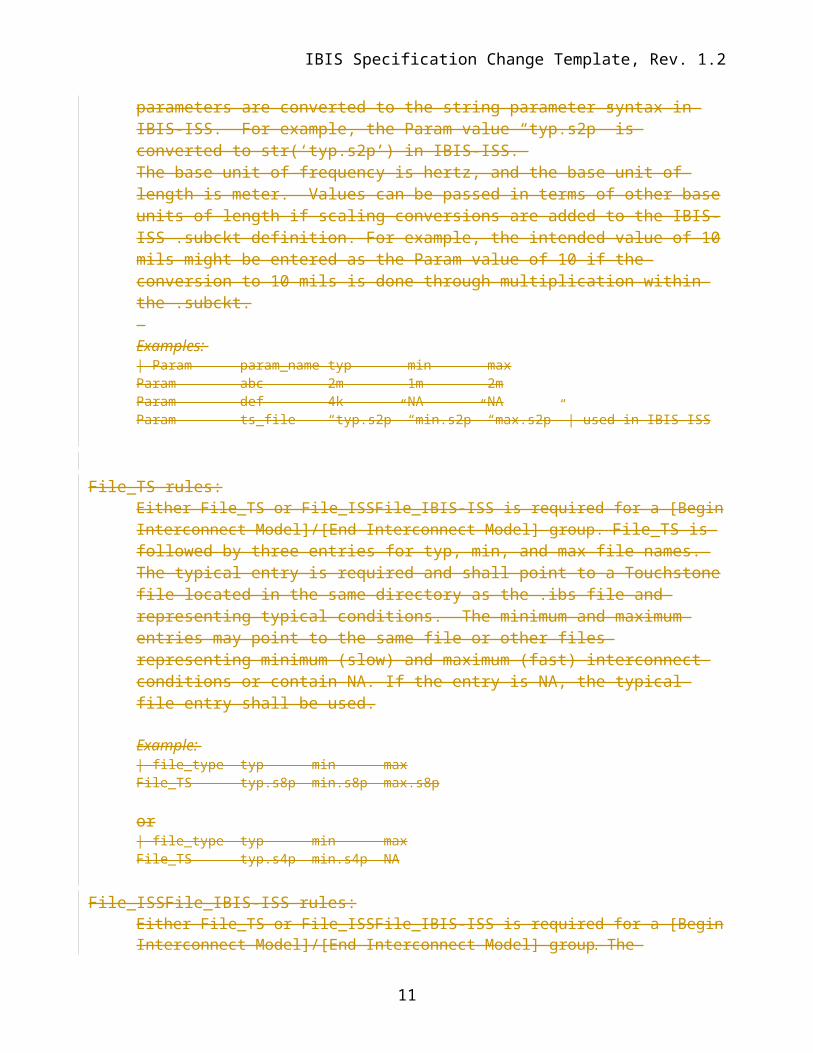
ohm, even though 1K is 1 kilohm in IBIS-ISS. Quoted string parameters are converted to the string parameter syntax in IBIS-ISS. For example, the Param value “typ.s2p” is converted to str(‘typ.s2p’) in IBIS-ISS. The base unit of frequency is hertz, and the base unit of length is meter. Values can be passed in terms of other base units of length if scaling conversions are added to the IBIS-ISS .subckt definition. For example, the intended value of 10 mils might be entered as the Param value of 10 if the conversion to 10 mils is done through multiplication within the .subckt. Examples: | Param param_name typ min maxParam abc 2m 1m 2mParam def 4k NA NAParam ts_file “typ.s2p” “min.s2p” “max.s2p” | used in IBIS-ISS
File_TS rules:Either File_TS or File_ISSFile_IBIS-ISS is required for a [Begin Interconnect Model]/[End Interconnect Model] group. File_TS is followed by three entries for typ, min, and max file names. The typical entry is required and shall point to a Touchstone file located in the same directory as the .ibs file and representing typical conditions. The minimum and maximum entries may point to the same file or other files representing minimum (slow) and maximum (fast) interconnect conditions or contain NA. If the entry is NA, the typical file entry shall be used.
Example: | file_type typ min maxFile_TS typ.s8p min.s8p max.s8p
or| file_type typ min maxFile_TS typ.s4p min.s4p NA
File_ISSFile_IBIS-ISS rules:Either File_TS or File_ISSFile_IBIS-ISS is required for a [Begin Interconnect Model]/[End Interconnect Model] group. The File_ISSFile_IBIS-ISS subparameter is followed by three string arguments consisting of corner_name, file_name, and circuit_name (.subckt name) for that file and located in the same directory as the .ibs file. The corner_name shall be Typ, Min, or Max. File_ISSFile_IBIS-ISS for the Typ corner_name is required, and File_ISSFile_IBIS-ISS for the Min and Max corner_names are optional. If present, each File_ISSFile_IBIS-ISS shall have a unique corner_name. If File_ISSFile_IBIS-ISS for either the Min or Max corner_name is missing, the File_ISSFile_IBIS-ISS for the Typ corner_name shall be used to describe the missing corner_name file reference. The Min and Max file_names should represent slow and fast interconnect conditions.
Can we get more than three corners? Is this speed, or impedance, or something else?
Author, 01/03/-1,
Same comment as above. This is even more similar to [External ***]…
Author, 01/03/-1,
Can we get more than three corners? Is this speed, or impedance, or something else?
Author, 01/03/-1,
Can we get more than three corners?
Author, 01/03/-1,
We might want to put these on separate lines, like it is done for [External ***]. That would allow us later to add more corner variants if desired, and reduce the issues with long files names and the line length… It would also be more consistent with the rest of the spec., even if you hate those keywords…
Author, 01/03/-1,
So what is the name of the keyword? This seems to be the 3rd variant I read so far. [Interconnect Model], [Begin Interconnect Mdoel], [Begin Model]?
Author, 01/03/-1,
So how would we distinguish between 2 meters and 2 millimeters (2m, or 2mm)if this was a length for a W-element? I know we can write 2 for meters and 2m for millimeters, but what if someone wants to write the unit meter to make sure people know it is not something else?
Author, 01/03/-1,
This is really not done on the subckt definition, it might be supplied by the model author inside the subcircuit.
IBIS Specification Change Template, Rev. 1.2
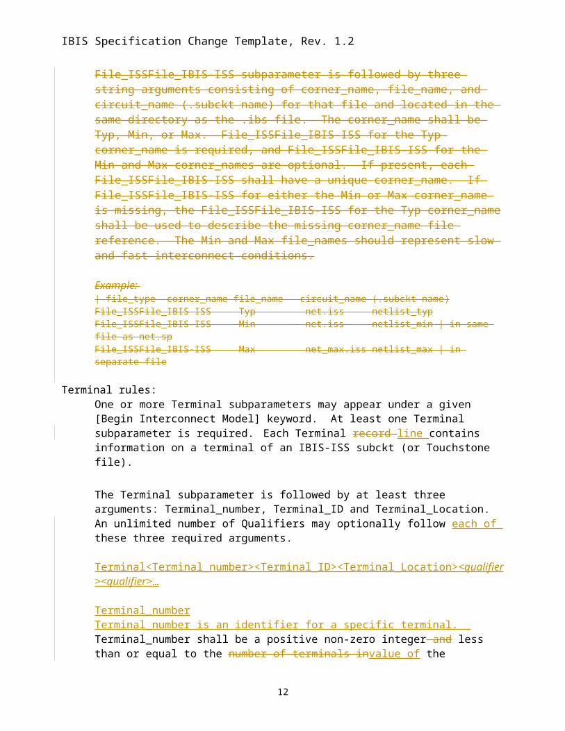
File_ISSFile_IBIS-ISS Min net.iss netlist_min | in same file as net.spFile_ISSFile_IBIS-ISS Max net_max.iss netlist_max | in separate file
Terminal rules: One or more Terminal subparameters may appear under a given [Begin Interconnect Model] keyword. At least one Terminal subparameter is required. Each Terminal record line contains information on a terminal of an IBIS-ISS subckt (or Touchstone file).
The Terminal subparameter is followed by at least three arguments: Terminal_number, Terminal_ID and Terminal_Location. An unlimited number of Qualifiers may optionally follow each of these three required arguments.
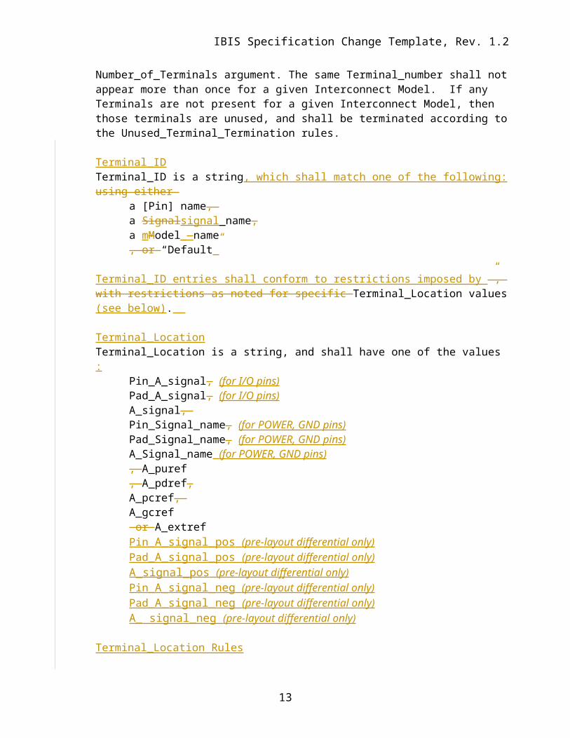
Terminal_numberTerminal_number is an identifier for a specific terminal. Terminal_number shall be a positive non-zero integer and less than or equal to the number of terminals invalue of the Number_of_Terminals argument. The same Terminal_number shall not appear more than once for a given Interconnect Model. If any Terminals are not present for a given Interconnect Model, then those terminals are unused, and shall be terminated according to the Unused_Terminal_Termination rules.
Terminal_IDTerminal_ID is a string, which shall match one of the following: using either
a [Pin] name, a Signalsignal_name, a mModel__name, or “Default”
Terminal_ID entries shall conform to restrictions imposed by ”, with restrictions as noted for specific Terminal_Location values (see below).
Terminal_LocationTerminal_Location is a string, and shall have one of the values :
Sub-bulleted list of items, rather than a complete sentence.
Author, 01/03/-1,
POWER not Power, throughout document referring to pins
Author, 01/03/-1,
Bob: anything called “A_signal” is an I/O rather than a power, ground, etc. ***_Signal_name should be lower case and can touch power, ground, etc. but excludes I/O pins. Suggests that Terminal 1-8 syntax in example is illegal (see middle of p. 15 of markup copy).
Author, 01/03/-1,
Bob: does it make more sense to list the Location before the ID in each line? In addition, list needs clarification to associate references to POWER, GND, pins, etc..
Author, 01/03/-1,
Need rule regarding matching of names between Interconnect and [Pin] information for the same, connected structure. Bob: must the Interconnect Model be complete, covering every pin, signal_name, model_name?
Author, 01/03/-1,
Bob: … from Pin list, which could be POWER or GND…
Author, 01/03/-1,
Check for N+1 matching rule, later in the document.
Author, 01/03/-1,
Match to IBIS-ISS, Touchstone?
Author, 01/03/-1,
Bob, Radek: Terminal_number refers to Touchstone port numbers, while the first, positive number is the port number (a port is defined by a pair of terminals). IBIS-ISS nodes are associated by node order, per SPICE. A separate paragraph would improve readability.
Author, 01/03/-1,
Section needs reorganization to clarify how Terminals and their sub-sub-parameters are associated. Bob: Table?
Author, 01/03/-1,
Show organizational hierarchy or non-literal example here?
Author, 01/03/-1,
Bob: remove “record” (line?).Randy: may a single Terminal alone be used?
Author, 01/03/-1,
Yes
Author, 01/03/-1,
Pre-layout vs. post-layout distinction here?
Author, 01/03/-1,
This doesn’t match the text above, but this is what I had in mind…
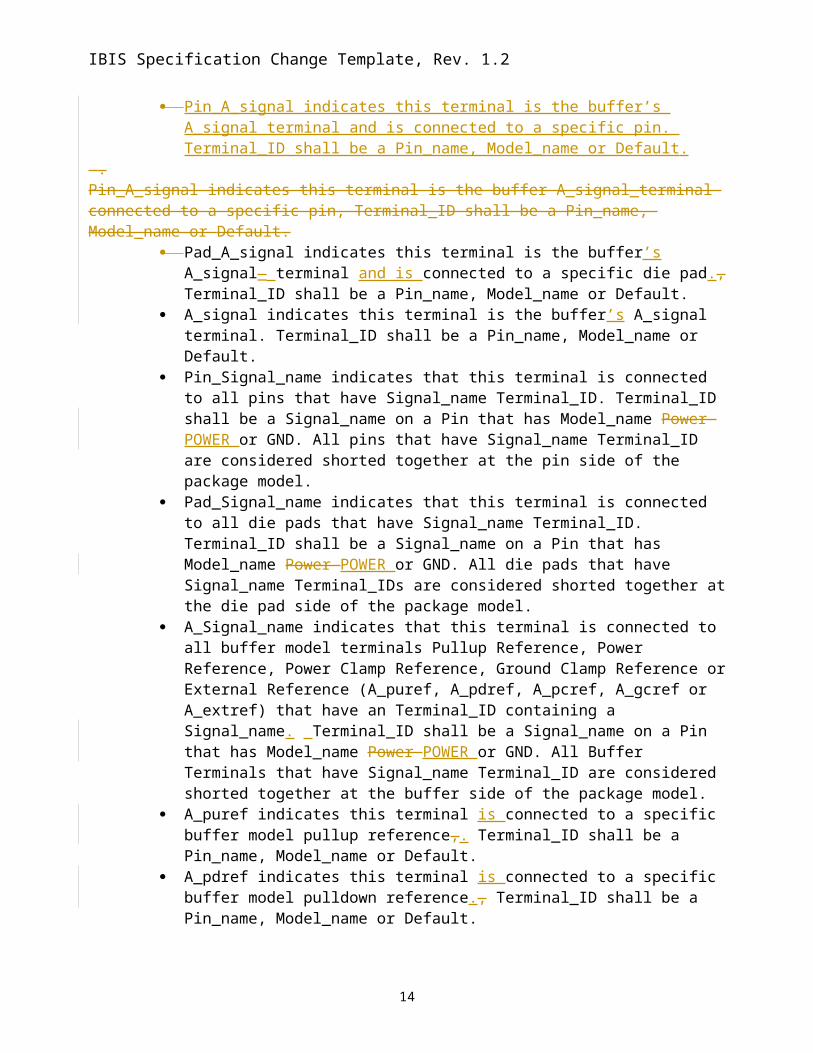
Pin_A_signal indicates this terminal is the buffer’s A_signal terminal and is connected to a specific pin. Terminal_ID shall be a Pin_name, Model_name or Default.
.Pin_A_signal indicates this terminal is the buffer A_signal_terminal connected to a specific pin, Terminal_ID shall be a Pin_name, Model_name or Default.
Pad_A_signal indicates this terminal is the buffer’s A_signal_ terminal and is connected to a specific die pad., Terminal_ID shall be a Pin_name, Model_name or Default.
A_signal indicates this terminal is the buffer’s A_signal terminal. Terminal_ID shall be a Pin_name, Model_name or Default.
Pin_Signal_name indicates that this terminal is connected to all pins that have Signal_name Terminal_ID. Terminal_ID shall be a Signal_name on a Pin that has Model_name Power POWER or GND. All pins that have Signal_name Terminal_ID are considered shorted together at the pin side of the package model.
Pad_Signal_name indicates that this terminal is connected to all die pads that have Signal_name Terminal_ID. Terminal_ID shall be a Signal_name on a Pin that has Model_name Power POWER or GND. All die pads that have Signal_name Terminal_IDs are considered shorted together at the die pad side of the package model.
A_Signal_name indicates that this terminal is connected to all buffer model terminals Pullup Reference, Power Reference, Power Clamp Reference, Ground Clamp Reference or External Reference (A_puref, A_pdref, A_pcref, A_gcref or A_extref) that have an Terminal_ID containing a Signal_name. Terminal_ID shall be a Signal_name on a Pin that has Model_name Power POWER or GND. All Buffer Terminals that have Signal_name Terminal_ID are considered shorted together at the buffer side of the package model.
A_puref indicates this terminal is connected to a specific buffer model pullup reference,. Terminal_ID shall be a Pin_name, Model_name or Default.
A_pdref indicates this terminal is connected to a specific buffer model pulldown reference., Terminal_ID shall be a Pin_name, Model_name or Default.
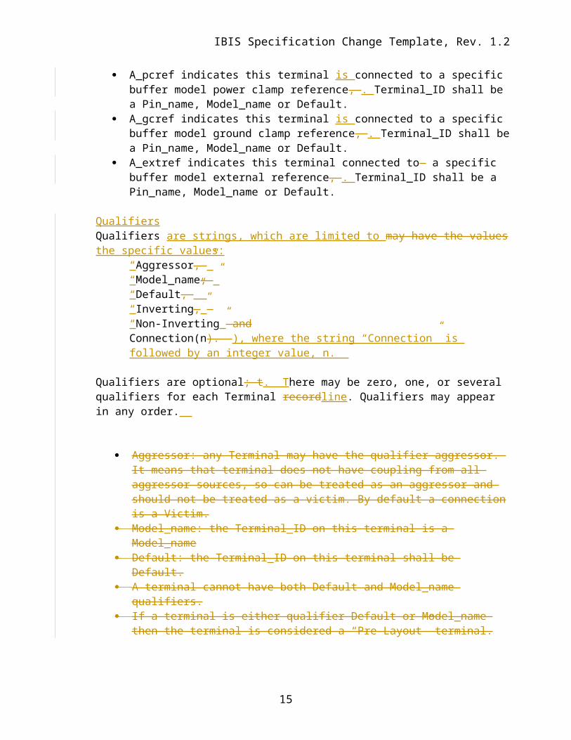
A_pcref indicates this terminal is connected to a specific buffer model power clamp reference, . Terminal_ID shall be a Pin_name, Model_name or Default.
A_gcref indicates this terminal is connected to a specific buffer model ground clamp reference, . Terminal_ID shall be a Pin_name, Model_name or Default.
A_extref indicates this terminal connected to a specific buffer model external reference, . Terminal_ID shall be a Pin_name, Model_name or Default.
QualifiersQualifiers are strings, which are limited to may have the values the specific values:
signal_name and model_name should be lower-case, to follow [Pin] column header format. We may need to refer to [Pin] as a reminder.
Author, 01/03/-1,
Mike suggests two columns in the table. Randy suggests third column, Terminal_ID. Some discussion of number of tables and whether rules can be only stated in a table.
Author, 01/03/-1,
Change entire listing to a table; add a diagram.
Author, 01/03/-1,
Arpad: Signal_name is the second column of [Pin]. Bob: confusing here, is this a buffer name reference?
Author, 01/03/-1,
Arpad: Pad_A_signal “is” the A_signal_terminal? Shorted? Same node? Walter: different points on the same connection. Radek: define the use of the prefixes as having a specific context. Bob: missing prefix means at the buffer interface.
Author, 01/03/-1,
Bob: an indentded list of available choices.
Author, 01/03/-1,
Bob: No such thing; remove the _ between terminal and signal
Author, 01/03/-1,
Is this defined?
Author, 01/03/-1,
Let’s be consistent with the spelling of similar reserved node names used for the [Esternal ***] keywords, such as “_puref” and “_pdref”, etc…
Author, 01/03/-1,
Is this defined?
Author, 01/03/-1,
Bob: "s" in "A_signal" should always be lower-case.
IBIS Specification Change Template, Rev. 1.2
“Non-Inverting” and Connection(n). ), where the string “Connection” is followed by an integer value, n.
Qualifiers are optional; t. There may be zero, one, or several qualifiers for each Terminal recordline. Qualifiers may appear in any order.
Aggressor: any Terminal may have the qualifier aggressor. It means that terminal does not have coupling from all aggressor sources, so can be treated as an aggressor and should not be treated as a victim. By default a connection is a Victim.
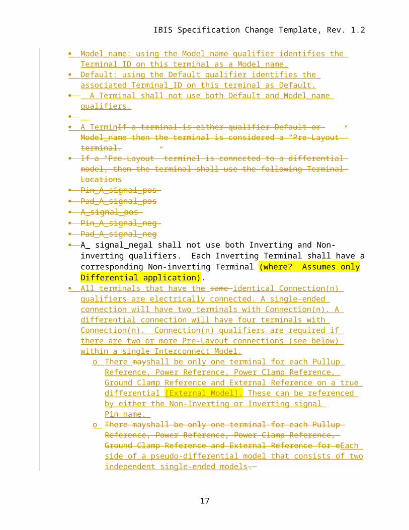
Model_name: the Terminal_ID on this terminal is a Model_name Default: the Terminal_ID on this terminal shall be Default. A terminal cannot have both Default and Model_name qualifiers. If a terminal is either qualifier Default or Model_name then the terminal is considered a
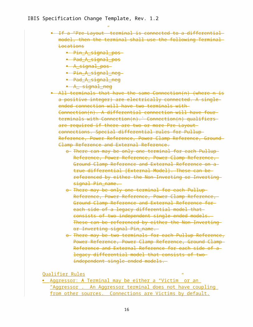
“Pre-Layout” terminal. If a “Pre-Layout” terminal is connected to a differential model, then the terminal shall
use the following Terminal Locations Pin_A_signal_pos Pad_A_signal_pos A_signal_pos Pin_A_signal_neg Pad_A_signal_neg A_ signal_neg
All terminals that have the same Connection(n) (where n is a positive integer) are electrically connected. A single-ended connection will have two terminals with Connection(n). A differential connection will have four terminals with Connection(n).` Connection(n) qualifiers are required if there are two or more Pre-Layout connections. Special differential rules for Pullup Reference, Power Reference, Power Clamp Reference, Ground Clamp Reference and External Reference.
o There can may be only one terminal for each Pullup Reference, Power Reference, Power Clamp Reference, Ground Clamp Reference and External Reference on a true differential [External Model]. These can be referenced by either the Non-Inverting or Inverting signal Pin_name.
o There may be only one terminal for each Pullup Reference, Power Reference, Power Clamp Reference, Ground Clamp Reference and External Reference for each side of a legacy differential model that consists of two independent single-ended models. These can be referenced by either the Non-Inverting or Inverting signal Pin_name.
o There may be two terminals for each Pullup Reference, Power Reference, Power Clamp Reference, Ground Clamp Reference and External Reference for each side of a legacy differential model that consists of two independent single-ended models.
Qualifier Rules Aggressor: A Terminal may be either a “Victim” or an “Aggressor”. An Aggressor
terminal does not have coupling from other sources. Connections are Victims by default. Model_name: using the Model_name qualifier identifies the Terminal_ID on this terminal
as a Model_name.
11
Author, 01/03/-1,
This is an I/O, not power/ground.
Author, 01/03/-1,
I would combine these last two bullets into one
Author, 01/03/-1,
I would put the word “signal” between those two words.here too.
Author, 01/03/-1,
I would put the word “signal” between those two words.
Author, 01/03/-1,
This is confusing with the differential case, because it could imply that the diff pair is shorted together…
Author, 01/03/-1,
This really doesn’t tell me what “default” actually means…
IBIS Specification Change Template, Rev. 1.2
Default: using the Default qualifier identifies the associated Terminal_ID on this terminal as Default.
A Terminal shall not use both Default and Model_name qualifiers. A TerminIf a terminal is either qualifier Default or Model_name then the terminal is
considered a “Pre-Layout” terminal. If a “Pre-Layout” terminal is connected to a differential model, then the terminal shall use
the following Terminal Locations Pin_A_signal_pos Pad_A_signal_pos A_signal_pos Pin_A_signal_neg Pad_A_signal_neg A_ signal_negal shall not use both Inverting and Non-inverting qualifiers. Each
Inverting Terminal shall have a corresponding Non-inverting Terminal (where? Assumes only Differential application).
All terminals that have the same identical Connection(n) qualifiers are electrically connected. A single-ended connection will have two terminals with Connection(n). A differential connection will have four terminals with Connection(n). Connection(n) qualifiers are required if there are two or more Pre-Layout connections (see below) within a single Interconnect Model.
o There mayshall be only one terminal for each Pullup Reference, Power Reference, Power Clamp Reference, Ground Clamp Reference and External Reference on a true differential [External Model]. These can be referenced by either the Non-Inverting or Inverting signal Pin_name.
o There mayshall be only one terminal for each Pullup Reference, Power Reference, Power Clamp Reference, Ground Clamp Reference and External Reference for eEach side of a pseudo-differential model that consists of two independent single-ended models.
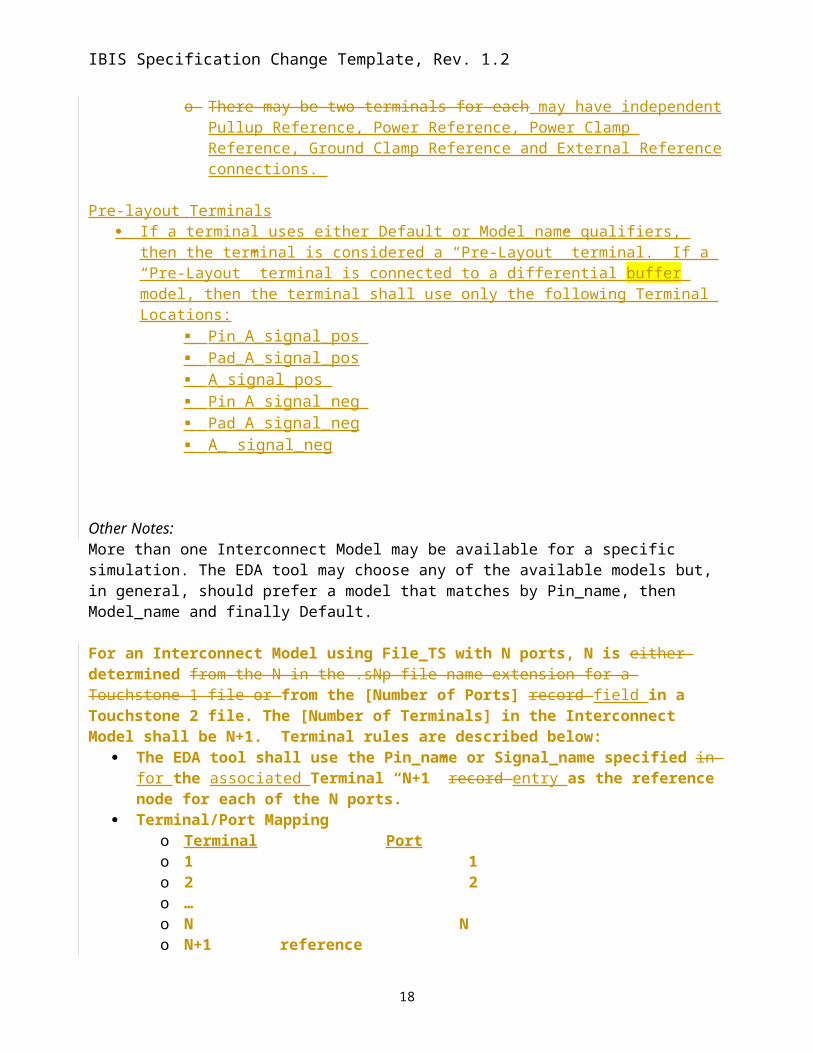
o There may be two terminals for each may have independent Pullup Reference, Power Reference, Power Clamp Reference, Ground Clamp Reference and External Reference connections.
Pre-layout Terminals If a terminal uses either Default or Model_name qualifiers, then the terminal is considered a
“Pre-Layout” terminal. If a “Pre-Layout” terminal is connected to a differential buffer model, then the terminal shall use only the following Terminal Locations:
Walter: All “signals” are terminals of the model, in a SPICE sense. Randy: Terminals list associates these with a pin or with a “generic” model which is identical/copied multiple times. A_signal of a specific pin, a specific buffer, or A_pin of a model or buffer.Mike: post-layout comes up twice in the specification, parenthetically.
Author, 01/03/-1,
How is "differential" defined? [Diff Pin]? Differential buffer type? Something else?
Author, 01/03/-1,
Walter:Pin number (IBIS) - postlayoutModel name – prelayoutFor supply pins…Signal_name may be pre- or post-layoutDistinction between pins and buffers on supply nets must be made, for power distribution simulations. Shorting pins together on power nets is common.
Author, 01/03/-1,
I would combine these last two bullets into one
Author, 01/03/-1,
May need to re-define pseudo-differential.
Author, 01/03/-1,
Pseudo-differential. NO checking of conflicting connections (Bob).
Author, 01/03/-1,
I would put the word “signal” between those two words.here too.
Author, 01/03/-1,
I would put the word “signal” between those two words.
Author, 01/03/-1,
This is confusing with the differential case, because it could imply that the diff pair is shorted together…
Author, 01/03/-1,
This really doesn’t tell me what “default” actually means…
IBIS Specification Change Template, Rev. 1.2
More than one Interconnect Model may be available for a specific simulation. The EDA tool may choose any of the available models but, in general, should prefer a model that matches by Pin_name, then Model_name and finally Default.
For an Interconnect Model using File_TS with N ports, N is either determined from the N in the .sNp file name extension for a Touchstone 1 file or from the [Number of Ports] record field in a Touchstone 2 file. The [Number of Terminals] in the Interconnect Model shall be N+1. Terminal rules are described below:
The EDA tool shall use the Pin_name or Signal_name specified in for the associated Terminal “N+1” record entry as the reference node for each of the N ports.
Terminal/Port Mappingo Terminal Porto 1 1o 2 2o …o N No N+1 reference
If a Port is not connected, then it shall be terminated by the EDA tool with a resistor to the node on Terminal N+1. The resistance shall be the Port Reference Impedance.
It shall be an error if Terminal N+1 is not specified to be connected to a Pin, a Pad, or a Buffer that is not on part of a connection to a Signal_name that is POWER or GND
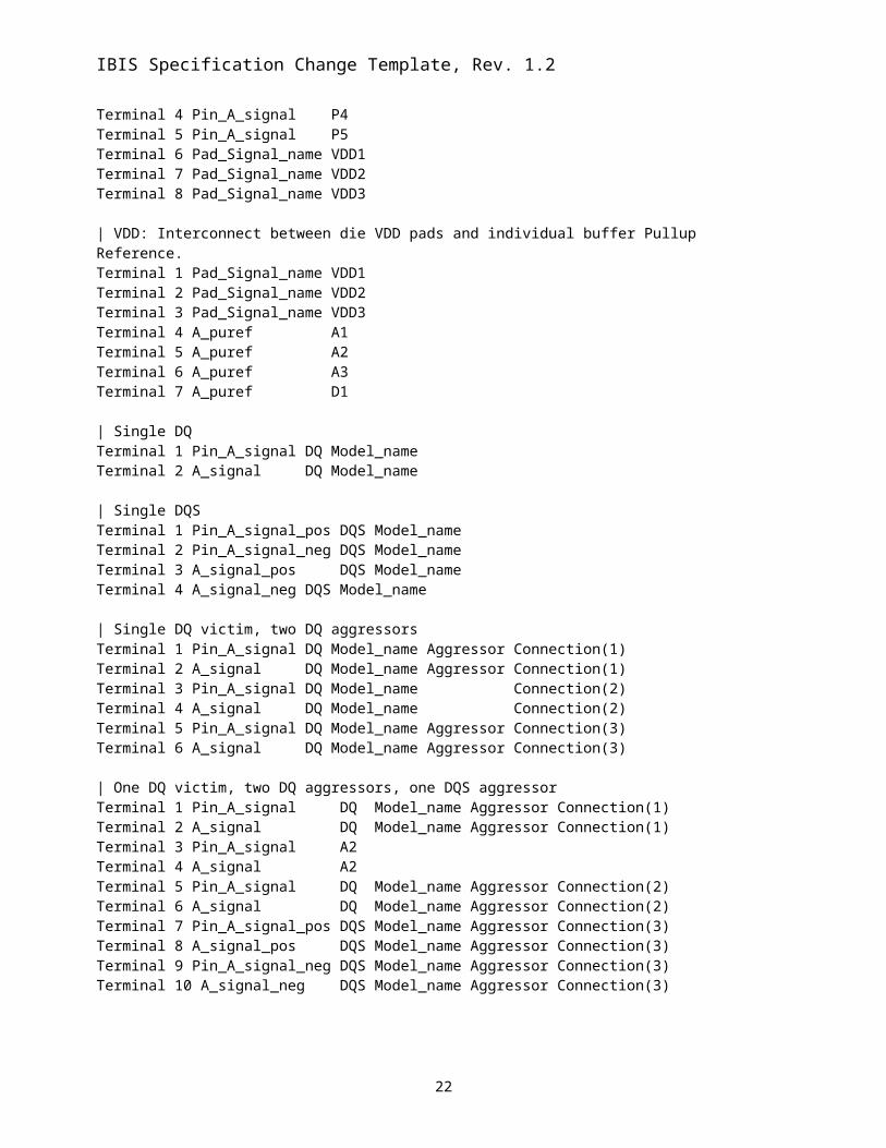
Examples:
13
Author, 01/03/-1,
What? (English)…
Author, 01/03/-1,
By whom? The model maker or the EDA tool?
Author, 01/03/-1,
What is the definition of “record”? Is it one line (below) or the entire table?
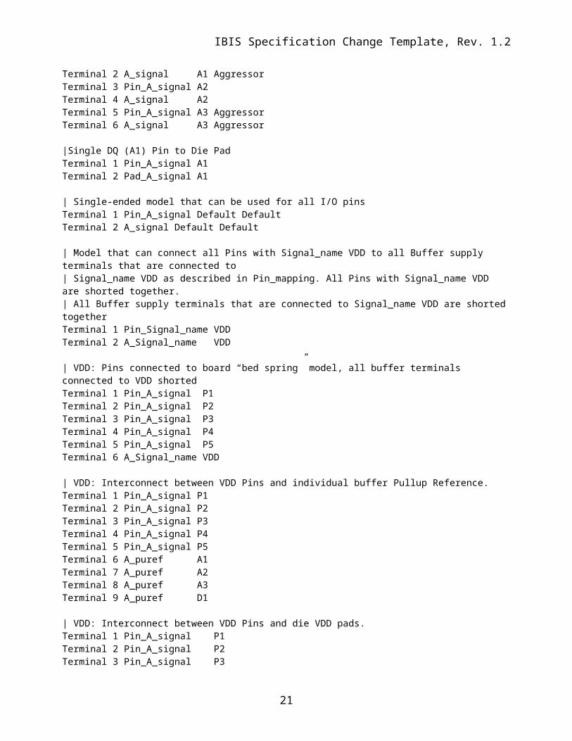
|Single DQ (A1) Pin to Die PadTerminal 1 Pin_A_signal A1Terminal 2 Pad_A_signal A1
14
IBIS Specification Change Template, Rev. 1.2
| Single-ended model that can be used for all I/O pinsTerminal 1 Pin_A_signal Default DefaultTerminal 2 A_signal Default Default
| Model that can connect all Pins with Signal_name VDD to all Buffer supply terminals that are connected to| Signal_name VDD as described in Pin_mapping. All Pins with Signal_name VDD are shorted together. | All Buffer supply terminals that are connected to Signal_name VDD are shorted togetherTerminal 1 Pin_Signal_name VDDTerminal 2 A_Signal_name VDD
How do you know which of these VDDx die pads belog to which [Model]’s upref terminal? I don’t see a way to trace that with this syntax.
Author, 01/03/-1,
This has to be reviewed carefully, because the [Pin Mapping] keyword doesn’t “observe” the 2nd column of the [Pin] keyword to make the connections on the pin side. As a consequence this “Terminal” syntax may have conflicts with [Pin Mapping] as writte here. I can see ways to make this work without such conflicts, but we need to discuss it and agree on it.
Keyword: [End Interconnect Model]Required: Yes, for each instance of the [Begin Interconnect Model] keywordDescription: Indicates the end of the Interconnect Model data. Other Notes: Between the [Begin Interconnect Model] and [End Interconnect Model] keywords is the package model data itself. The data describes any number of interfaces to either IBIS-ISS models or Touchstone files.Example: [End Interconnect Model]
Keyword: [End Interconnect Model Selector]Required: Yes, for each instance of the [Begin Interconnect Model Selector] keywordDescription: Indicates the end of the Interconnect Model selector data. Example: [End Interconnect Model Selector]
Keyword: [Die Supply Pads]Required: NoDescription: This begins a section in [Component] that contains one line of data assigning die pads as supply nodes. IBIS assumes that for I/O pins (pins that have a Model_name that is not POWER, GND or NC), there is a one-to-one correspondence between a Pin, a Die Pad and the Buffer I/O connection point. There are no such assumptions for POWER and GND pins. A POWER or GND Signal_name may have a different number of Pin nodes, die pad nodes and buffer nodes. If the model maker chooses to make separate package and on-die power distribution networks (PDN), then he shall supply a list of nodes (and their associated Signal_name) that can be used to mate the package and on-die PDN models.Sub-Params: NoneUsage Rules: Arguments under the [Die Supply Pads] keyword consist of two strings per line, where the strings define a die pad node name and a corresponding Signal_name, in that order. Signal_names may appear multiple times, but die pad node names may appear only once each under the [Die Supply Pads] keyword.Other Notes: The data in this section consists of a list of die pad node names and their corresponding Signal_names that can be used to mate package and on-die PDN networks.
17
Author, 01/03/-1,
That is actually not quite correct, although the spec doesn’t spell out any of these assumptions. The [Pin Mapping] keyword is the “living proof” for the unstated assumptions. Even though the 1st column of the [Pin Mapping] keyword uses pin names, the assumption was that in reality these pin names are actually pad names, which are behind the pcakge model, which connects each pin to a corresponding pad with a 1:1 mapping.I agree that the number of buffer model power/gnd terminals is not restricted to be the same as the number of power/gnd pads, because buffer models can be grouped with power/gnd terminals shorted. So there is some freedom there, but due to the nature of the syntax, the number of buffer power/gnd terminals can’t be larger than the corresponding number of power/gnd pads, they can only be fewer in numbers.
Keyword: [End Die Supply Pads]Required: YesDescription: Indicates the end of the [Die Supply Pads] data.Other Notes: Example: [End Die Supply Pads]
18
Author, 01/03/-1,
What is the significance or meaning of the 2nd column? Is that used for any purpose? If not, the existing [Nodel Declarations] keyword could be used for the same purpose and we wouldn’t have to add a new keyword for this reason.
IBIS Specification Change Template, Rev. 1.2
Examples[Define Package Model]
[Begin Interconnect Model] IOA3| file_name typ min maxFile_TS ioA3.s2p NA NANumber_of_Terminals = 2Terminal 1 Pin_A_signal Pin_name A3Terminal 2 A_signal Pin_name A3Terminal 3 Pin_Signal_name VSS [End Interconnect Model]
[Begin Interconnect Model] IOA7| This model uses I/O pin A7 | file_name typ min maxFile_TS ioA7.s2p NA NANumber_of_Terminals = 2Terminal 1 Pin_A_signal A7 Terminal 2 A_signal A7Terminal 3 Pin_Signal_name VSS [End Interconnect Model] [Begin Interconnect Model] IOB3C3| file_name typ min maxFile_TS ioB3C3.s4p NA NANumber_of_Terminals = 4Terminal 1 Pin_A_signal Pin_name B3Terminal 2 A_Signal Pin_name B3 Terminal 3 Pin_A_signal Pin_name C3Terminal 4 A_Signal Pin_name C3 Terminal 5 Pin_Signal_name VSS [End Interconnect Model]
The following section should be included in Chapter 5, Component Modeling.
Keyword: [Buffer Rail Mapping]Required: NoDescription: Used to indicate the signal_name to which a given driver, receiver or terminator is connected.Sub-Params: pulldown_ref, pullup_ref, gnd_clamp_ref, power_clamp_ref, ext_refUsage Rules: The [Buffer Rail Mapping] defines the connections between POWER and/or GND pins and buffer and/or terminator voltage supply references using signal_name. When [Buffer Rail Mapping] is present, then the signal_name field (second column of [Pin] records) shall indicate that all POWER and GND pins with the same signal_name are connected.Each line shall contain either three, five or six entries. Use the reserved word NC for columns where a connection is not made.
20
Author, 01/03/-1,
I am getting tired in my mind, but isn’t this supposed to be the syntax in which “connection(n)” was used in the explanation above? If so, we should “update” this example to match the text above.
IBIS Specification Change Template, Rev. 1.2
The first column contains a pin name. Each pin name shall match one of the pin names declared in the [Pin] section of the [Component] as a buffer or terminator. The remaining columns correspond to the voltage supply references for the named pin. Each [Model] supply reference is connected to a signal_name in the corresponding column. The second column, pulldown_ref, designates the ground (GND) signal_name for the buffer or termination associated with that pin. The signal_name under pulldown_ref is associated with the [Pulldown] I-V table for non-ECL [Model]s. This is also the signal_name associated with the [GND Clamp] I-V table and the [Rgnd] model unless overridden by a label in the gnd_clamp_ref column.The third column, pullup_ref, designates the power (POWER) signal_name for the buffer or termination. The signal_name under pullup_ref is associated with the [Pullup] table for non-ECL [Model]s (for ECL models, this bus is associated with the [Pulldown] table). This is also the signal_name associated with the [POWER Clamp] I-V table and the [Rpower] model unless overridden by a label in the power_clamp_ref column.The fourth and fifth columns, gnd_clamp_ref and power_clamp_ref, contain entries, if needed, to specify additional ground signal_name and power signal_name connections for clamps. Finally, the sixth column, ext_ref, contains entries to specify external reference supply signal_name connections.There shall be no entries for pins listed under the [Pin] keyword with model_name GND, POWER and NC.If the [Buffer Rail Mapping] keyword is present, then the supply reference connections for every pin listed under the [Pin] keyword (except POWER, GND and NC pins) shall be given.The column length limits are:
The following section should be appended to the end of the IBIS document.
12 RULES OF PRECEDENCEThe sections below detail the rules of precedence to be assumed by EDA tools and model makers where multiple keywords may support similar functions.
12.1 PACKAGESThe order of precedence for package model data to be used by EDA tools in simulation is defined below, in ascending order. If a package data format at a numerically higher position on the list is available in an IBIS or related file, that data shall be used by the EDA tool for simulation; any data present in formats numerically lower on the list shall be ignored.
1. [Component]/[Package] 2. [Component]/[Pin] 3. [Package Model] (including [Alternate Package Models] and [Define Package Model])4. [Interconnect Model Selector]