IBIS Specification Change Template, Rev. 1.2 BUFFER ISSUE RESOLUTION DOCUMENT (BIRD) BIRD NUMBER: 189.5_draft9 ISSUE TITLE: Interconnect Modeling Using IBIS-ISS and Touchstone REQUESTOR: Walter Katz, Signal Integrity Software (SiSoft); Radek Biernacki, Keysight Technologies; Justin Butterfield, Micron Technology; Curtis Clark, ANSYS; Mike LaBonte, Signal Integrity Software (SiSoft); Arpad Muranyi, Mentor Graphics; Michael Mirmak, Intel Corp.; Bob Ross, Teraspeed Labs; Randy Wolff, Micron Technology DATE SUBMITTED: January 27, 2017 DATE REVISED: March 29, 2017; April 19, 2017; April 26, 2017; June 22, 2017 DATE ACCEPTED: STATEMENT OF THE ISSUE: This BIRD enhances IBIS with interconnect modeling features to support broadband, coupled package, and on-die interconnect using IBIS-ISS and Touchstone data. The BIRD also adds a keyword for buffer rail mapping, to link to new terminal definitions defined for buffers. ANALYSIS PATH/DATA THAT LED TO SPECIFICATION: This BIRD has resulted from several years of discussion regarding the need for more flexible description of interconnects in IBIS. It was decided to avoid a keyword-based approach, in favor of a circuit language approach. IBIS-ISS was developed for this purpose, and a means to instantiate IBIS-ISS models from IBIS became the logical next step. 1
Transcript
IBIS Specification Change Template, Rev. 1.2
BUFFER ISSUE RESOLUTION DOCUMENT (BIRD)
BIRD NUMBER: 189.5_draft9ISSUE TITLE: Interconnect Modeling Using IBIS-ISS and TouchstoneREQUESTOR: Walter Katz, Signal Integrity Software (SiSoft); Radek Biernacki,
Keysight Technologies; Justin Butterfield, Micron Technology; Curtis Clark, ANSYS; Mike LaBonte, Signal Integrity Software (SiSoft); Arpad Muranyi, Mentor Graphics; Michael Mirmak, Intel Corp.; Bob Ross, Teraspeed Labs; Randy Wolff, Micron Technology
DATE SUBMITTED: January 27, 2017DATE REVISED: March 29, 2017; April 19, 2017; April 26, 2017; June 22, 2017DATE ACCEPTED:
STATEMENT OF THE ISSUE:
This BIRD enhances IBIS with interconnect modeling features to support broadband, coupled package, and on-die interconnect using IBIS-ISS and Touchstone data.
The BIRD also adds a keyword for buffer rail mapping, to link to new terminal definitions defined for buffers.
ANALYSIS PATH/DATA THAT LED TO SPECIFICATION:
This BIRD has resulted from several years of discussion regarding the need for more flexible description of interconnects in IBIS. It was decided to avoid a keyword-based approach, in favor of a circuit language approach. IBIS-ISS was developed for this purpose, and a means to instantiate IBIS-ISS models from IBIS became the logical next step.
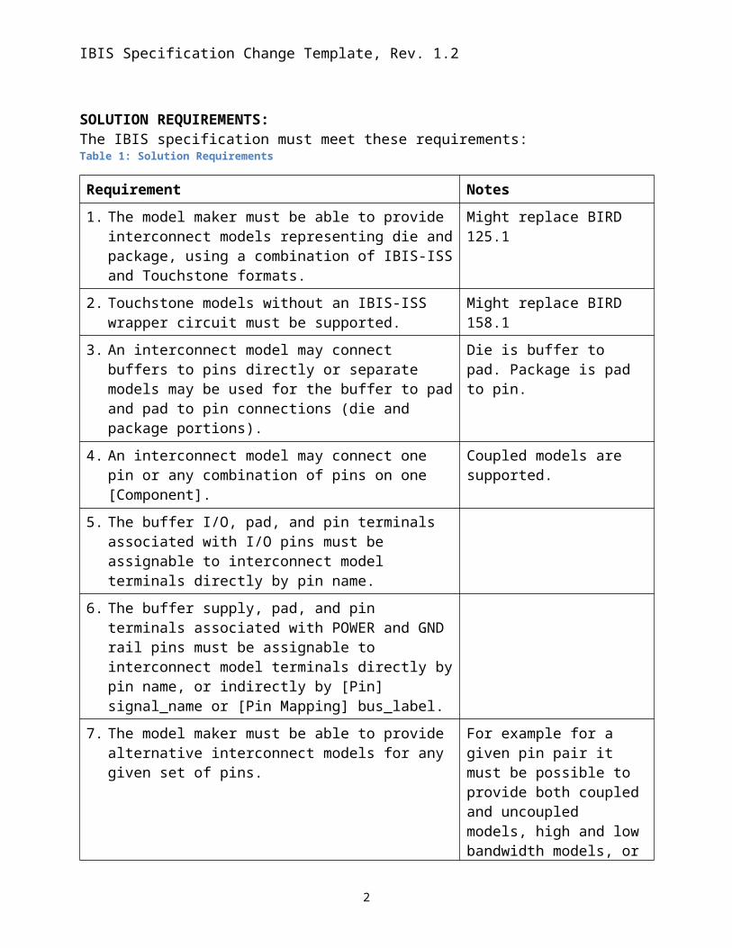
SOLUTION REQUIREMENTS:The IBIS specification must meet these requirements:Table 1: Solution Requirements
Requirement Notes
1. The model maker must be able to provide interconnect models representing die and package, using a combination of IBIS-ISS and Touchstone formats.
Might replace BIRD 125.1
2. Touchstone models without an IBIS-ISS wrapper circuit must be supported.
Might replace BIRD 158.1
3. An interconnect model may connect buffers to pins directly or separate models may be used for the buffer to pad and
Die is buffer to pad. Package is pad to pin.
1
IBIS Specification Change Template, Rev. 1.2
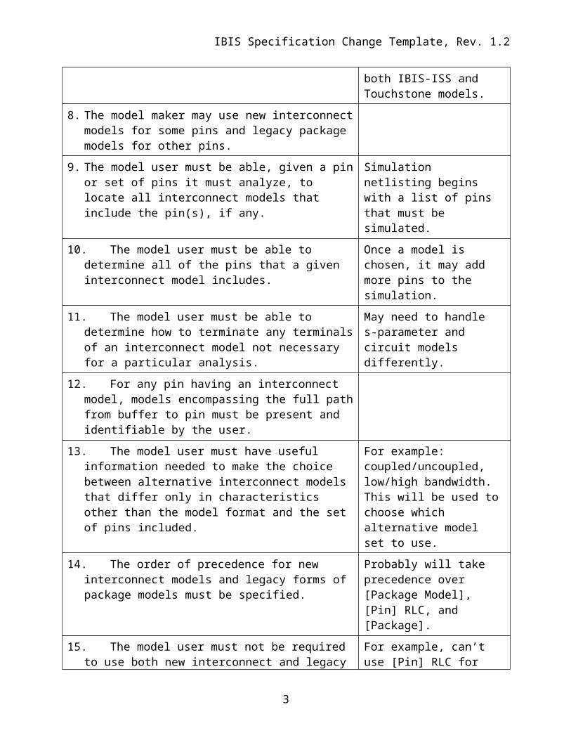
pad to pin connections (die and package portions).
4. An interconnect model may connect one pin or any combination of pins on one [Component].
Coupled models are supported.
5. The buffer I/O, pad, and pin terminals associated with I/O pins must be assignable to interconnect model terminals directly by pin name.
6. The buffer supply, pad, and pin terminals associated with POWER and GND rail pins must be assignable to interconnect model terminals directly by pin name, or indirectly by [Pin] signal_name or [Pin Mapping] bus_label.
7. The model maker must be able to provide alternative interconnect models for any given set of pins.
For example for a given pin pair it must be possible to provide both coupled and uncoupled models, high and low bandwidth models, or both IBIS-ISS and Touchstone models.
8. The model maker may use new interconnect models for some pins and legacy package models for other pins.
9. The model user must be able, given a pin or set of pins it must analyze, to locate all interconnect models that include the pin(s), if any.
Simulation netlisting begins with a list of pins that must be simulated.
10. The model user must be able to determine all of the pins that a given interconnect model includes.
Once a model is chosen, it may add more pins to the simulation.
11. The model user must be able to determine how to terminate any terminals of an interconnect model not necessary for a particular analysis.
May need to handle s-parameter and circuit models differently.
12. For any pin having an interconnect model, models encompassing the full path from buffer to pin must be present and identifiable by the user.
13. The model user must have useful information needed to make the choice between alternative interconnect models that differ only in characteristics other than the model format and the set of pins included.
For example: coupled/uncoupled, low/high bandwidth. This will be used to choose which alternative model set to use.
14. The order of precedence for new interconnect models and legacy forms of package models must be specified.
Probably will take precedence over [Package Model], [Pin] RLC, and [Package].
15. The model user must not be required to use both new For example, can’t use [Pin]
2
IBIS Specification Change Template, Rev. 1.2
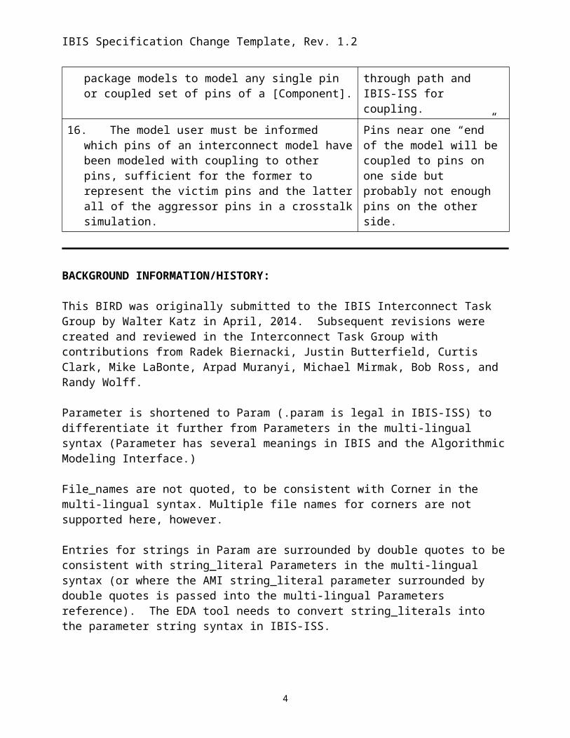
interconnect and legacy package models to model any single pin or coupled set of pins of a [Component].
RLC for through path and IBIS-ISS for coupling.
16. The model user must be informed which pins of an interconnect model have been modeled with coupling to other pins, sufficient for the former to represent the victim pins and the latter all of the aggressor pins in a crosstalk simulation.
Pins near one “end” of the model will be coupled to pins on one side but probably not enough pins on the other side.
BACKGROUND INFORMATION/HISTORY:
This BIRD was originally submitted to the IBIS Interconnect Task Group by Walter Katz in April, 2014. Subsequent revisions were created and reviewed in the Interconnect Task Group with contributions from Radek Biernacki, Justin Butterfield, Curtis Clark, Mike LaBonte, Arpad Muranyi, Michael Mirmak, Bob Ross, and Randy Wolff.
Parameter is shortened to Param (.param is legal in IBIS-ISS) to differentiate it further from Parameters in the multi-lingual syntax (Parameter has several meanings in IBIS and the Algorithmic Modeling Interface.)
File_names are not quoted, to be consistent with Corner in the multi-lingual syntax. Multiple file names for corners are not supported here, however.
Entries for strings in Param are surrounded by double quotes to be consistent with string_literal Parameters in the multi-lingual syntax (or where the AMI string_literal parameter surrounded by double quotes is passed into the multi-lingual Parameters reference). The EDA tool needs to convert string_literals into the parameter string syntax in IBIS-ISS.
Interaction of Param entries was not discussed. For example, for a transmission line, TD and Z0 could each have max and min entries, but the EDA tool could make available combinations of min/min, min/max, max/min or max/max for any corner. Due to parameter interactions, some mixing of corner combinations might not be realistic. (E.g., Z0min or Z0max might not correlate with TDmin or TDmax values, where TDmin=sqrt(LminCmin), Z0min=sqrt(Lmin/Cmax), etc.).How corners of File_IBIS-ISS and Params are processed might be based on vendor supplied documentation. For example some, but not all, combinations are shown below:
1. One file_name for all corners, one .subckt name, and all corner settings controlled by Param settings
2. One file_name, three .subckts (with internal default .param settings), additional corner settings controlled by Param settings or Param is not used
3. Three file_names with the same .subckt name, but with distinct default .param settings, additional settings controlled by Param settings or Param is not used
4. Three file_names with three distinct .subckt name and with distinct default .param settings, additional corner settings controlled by Param settings or Param is not used
3
IBIS Specification Change Template, Rev. 1.2
No interpretation is given for Param typ, min, and max values. It is possible to independently use typ, min, or max values for any of the Param names that have been defined (e.g., the max value of one parameter may be used with the min value of another parameter).
Some concern has been noted that EDA tools may not be able to clearly define a complete interconnect path from separate Interconnect Models that specify only part of the electrical path. While several methods to do this are possible, an example flow for an EDA tool to assemble a complete interconnect path from separate Interconnect Models is as follows:
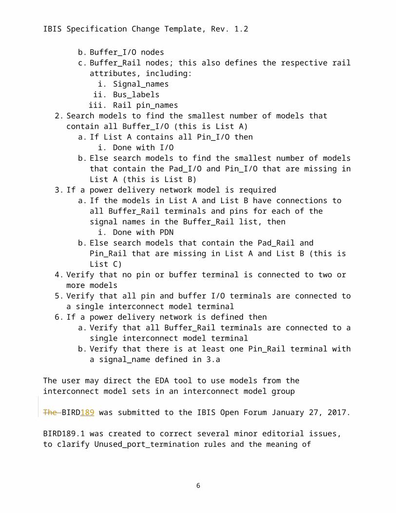
1. Read in the list of I/O buffers; this must contain:a. Pin_I/O nodesb. Buffer_I/O nodesc. Buffer_Rail nodes; this also defines the respective rail attributes, including:
i. Signal_namesii. Bus_labels
iii. Rail pin_names2. Search models to find the smallest number of models that contain all Buffer_I/O (this is List
A)a. If List A contains all Pin_I/O then
i. Done with I/Ob. Else search models to find the smallest number of models that contain the Pad_I/O
and Pin_I/O that are missing in List A (this is List B)3. If a power delivery network model is required
a. If the models in List A and List B have connections to all Buffer_Rail terminals and pins for each of the signal names in the Buffer_Rail list, then
i. Done with PDNb. Else search models that contain the Pad_Rail and Pin_Rail that are missing in List A
and List B (this is List C)4. Verify that no pin or buffer terminal is connected to two or more models5. Verify that all pin and buffer I/O terminals are connected to a single interconnect model
terminal6. If a power delivery network is defined then
a. Verify that all Buffer_Rail terminals are connected to a single interconnect model terminal
b. Verify that there is at least one Pin_Rail terminal with a signal_name defined in 3.a
The user may direct the EDA tool to use models from the interconnect model sets in an interconnect model group
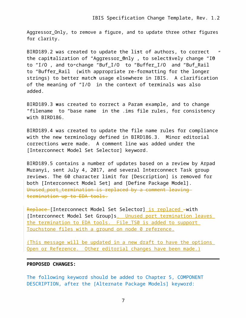
The BIRD189 was submitted to the IBIS Open Forum January 27, 2017.
BIRD189.1 was created to correct several minor editorial issues, to clarify Unused_port_termination rules and the meaning of Aggressor_Only, to remove a figure, and to update three other figures for clarity.
4
IBIS Specification Change Template, Rev. 1.2
BIRD189.2 was created to update the list of authors, to correct the capitalization of “Aggressor_Only”, to selectively change “IO” to “I/O”, and to change “Buf_I/O” to “Buffer_I/O” and “Buf_Rail” to “Buffer_Rail” (with appropriate re-formatting for the longer strings) to better match usage elsewhere in IBIS. A clarification of the meaning of “I/O” in the context of terminals was also added.
BIRD189.3 was created to correct a Param example, and to change “filename” to “base name” in the .ims file rules, for consistency with BIRD186.
BIRD189.4 was created to update the file name rules for compliance with the new terminology defined in BIRD186.3. Minor editorial corrections were made. A comment line was added under the [Interconnect Model Set Selector] keyword.
BIRD189.5 contains a number of updates based on a review by Arpad Muranyi, sent July 4, 2017, and several Interconnect Task group reviews. The 60 character limit for [Description] is removed for both [Interconnect Model Set] and [Define Package Model]. Unused_port_termination is replaced by a comment leaving termination up to EDA tools.
Replace [Interconnect Model Set Selector] is replaced with [Interconnect Model Set Group]s. Unused_port_termination leaves the termination to EDA tools. File_TS0 is added to support Touchstone files with a ground on node 0 reference.
(This message will be updated in a new draft to have the options Open or Reference. Other editorial changes have been made.)
PROPOSED CHANGES:
The following keyword should be added to Chapter 5, COMPONENT DESCRIPTION, after the [Alternate Package Models] keyword:
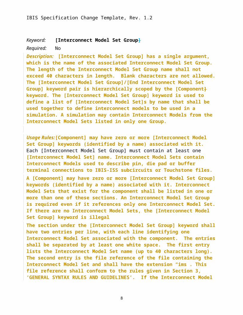
Keyword: [Interconnect Model Set Group]Required: NoDescription: [Interconnect Model Set Group] has a single argument, which is the name of the associated Interconnect Model Set Group. The length of the Interconnect Model Set Group name shall not exceed 40 characters in length. Blank characters are not allowed. The [Interconnect Model Set Group]/[End Interconnect Model Set Group] keyword pair is hierarchically scoped by the [Component] keyword. The [Interconnect Model Set Group] keyword is used to define a list of [Interconnect Model Set]s by name that shall be used together to define interconnect models to be used in a simulation. A simulation may contain Interconnect Models from the Interconnect Model Sets listed in only one Group.
Usage Rules: [Component] may have zero or more [Interconnect Model Set Group] keywords (identified by a name) associated with it. Each [Interconnect Model Set Group] must contain at least one [Interconnect Model Set] name. Interconnect Model Sets contain
5
IBIS Specification Change Template, Rev. 1.2
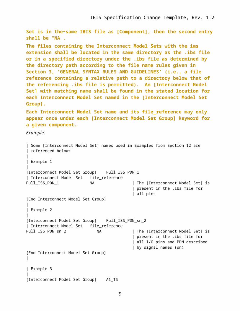
Interconnect Models used to describe pin, die pad or buffer terminal connections to IBIS-ISS subcircuits or Touchstone files.A [Component] may have zero or more [Interconnect Model Set Group] keywords (identified by a name) associated with it. Interconnect Model Sets that exist for the component shall be listed in one or more than one of these sections. An Interconnect Model Set Group is required even if it references only one Interconnect Model Set. If there are no Interconnect Model Sets, the [Interconnect Model Set Group] keyword is illegalThe section under the [Interconnect Model Set Group] keyword shall have two entries per line, with each line identifying one Interconnect Model Set associated with the component. The entries shall be separated by at least one white space. The first entry lists the Interconnect Model Set name (up to 40 characters long). The second entry is the file reference of the file containing the Interconnect Model Set and shall have the extension “ims”. This file reference shall conform to the rules given in Section 3, ‘GENERAL SYNTAX RULES AND GUIDELINES’. If the Interconnect Model Set is in the same IBIS file as [Component], then the second entry shall be “NA”. The files containing the Interconnect Model Sets with the ims extension shall be located in the same directory as the .ibs file or in a specified directory under the .ibs file as determined by the directory path according to the file name rules given in Section 3, ’GENERAL SYNTAX RULES AND GUIDELINES’ (i.e., a file reference containing a relative path to a directory below that of the referencing .ibs file is permitted). An [Interconnect Model Set] with matching name shall be found in the stated location for each Interconnect Model Set named in the [Interconnect Model Set Group].Each Interconnect Model Set name and its file_reference may only appear once under each [Interconnect Model Set Group] keyword for a given component.Example:
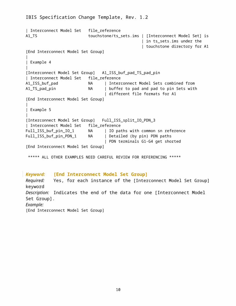
| Some [Interconnect Model Set] names used in Examples from Section 12 are| referenced below:|| Example 1|[Interconnect Model Set Group] Full_ISS_PDN_1| Interconnect Model Set file_referenceFull_ISS_PDN_1 NA | The [Interconnect Model Set] is | present in the .ibs file for | all pins[End Interconnect Model Set Group]|| Example 2|[Interconnect Model Set Group] Full_ISS_PDN_sn_2| Interconnect Model Set file_referenceFull_ISS_PDN_sn_2 NA | The [Interconnect Model Set] is | present in the .ibs file for | all I/O pins and PDN described | by signal_names (sn) [End Interconnect Model Set Group]|
6
IBIS Specification Change Template, Rev. 1.2
| Example 3|[Interconnect Model Set Group] A1_TS| Interconnect Model Set file_referenceA1_TS touchstone/ts_sets.ims | [Interconnect Model Set] is | in ts_sets.ims under the | touchstone directory for A1[End Interconnect Model Set Group]|| Example 4|[Interconnect Model Set Group] A1_ISS_buf_pad_TS_pad_pin| Interconnect Model Set file_referenceA1_ISS_buf_pad NA | Interconnect Model Sets combined fromA1_TS_pad_pin NA | buffer to pad and pad to pin Sets with | different file formats for A1[End Interconnect Model Set Group]|| Example 5|[Interconnect Model Set Group] Full_ISS_split_IO_PDN_3 | Interconnect Model Set file_referenceFull_ISS_buf_pin_IO_1 NA | IO paths with common sn referenceFull_ISS_buf_pin_PDN_1 NA | Detailed (by pin) PDN paths | PDN terminals G1-G4 get shorted[End Interconnect Model Set Group]
***** ALL OTHER EXAMPLES NEED CAREFUL REVIEW FOR REFERENCING *****
Keyword: [End Interconnect Model Set Group]Required: Yes, for each instance of the [Interconnect Model Set Group] keywordDescription: Indicates the end of the data for one [Interconnect Model Set Group]. Example: [End Interconnect Model Set Group]
7
IBIS Specification Change Template, Rev. 1.2
The following keywords should be placed in section 5, COMPONENT DESCRIPTION, after the [Pin Mapping] keyword.
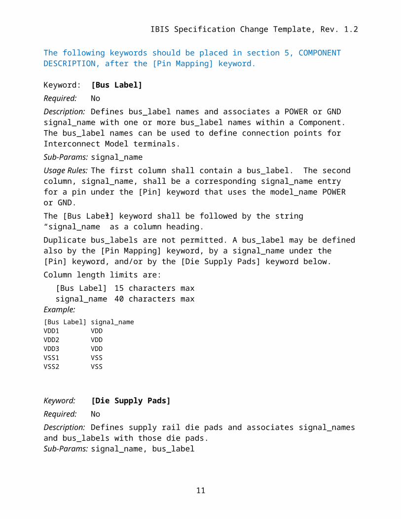
Keyword: [Bus Label]Required: NoDescription: Defines bus_label names and associates a POWER or GND signal_name with one or more bus_label names within a Component. The bus_label names can be used to define connection points for Interconnect Model terminals. Sub-Params: signal_nameUsage Rules: The first column shall contain a bus_label. The second column, signal_name, shall be a corresponding signal_name entry for a pin under the [Pin] keyword that uses the model_name POWER or GND.The [Bus Label] keyword shall be followed by the string “signal_name” as a column heading.Duplicate bus_labels are not permitted. A bus_label may be defined also by the [Pin Mapping] keyword, by a signal_name under the [Pin] keyword, and/or by the [Die Supply Pads] keyword below. Column length limits are:
[Bus Label] 15 characters maxsignal_name 40 characters max
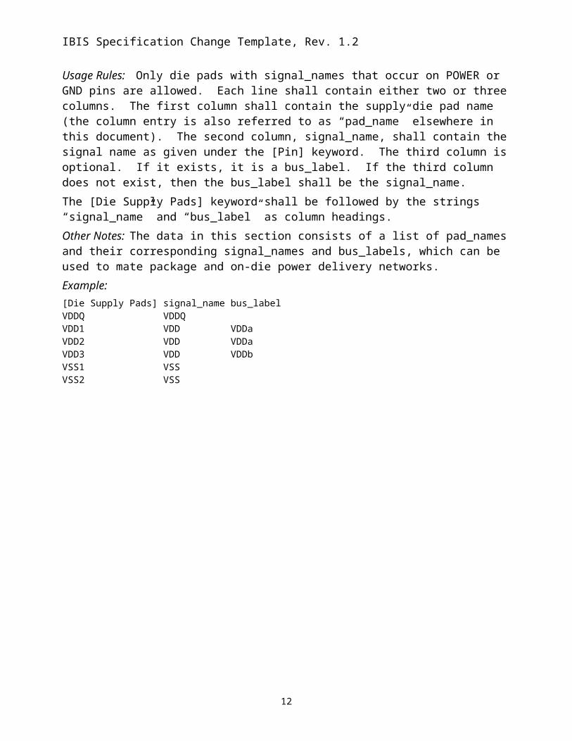
Keyword: [Die Supply Pads]Required: NoDescription: Defines supply rail die pads and associates signal_names and bus_labels with those die pads.Sub-Params: signal_name, bus_labelUsage Rules: Only die pads with signal_names that occur on POWER or GND pins are allowed. Each line shall contain either two or three columns. The first column shall contain the supply die pad name (the column entry is also referred to as “pad_name” elsewhere in this document). The second column, signal_name, shall contain the signal name as given under the [Pin] keyword. The third column is optional. If it exists, it is a bus_label. If the third column does not exist, then the bus_label shall be the signal_name.The [Die Supply Pads] keyword shall be followed by the strings “signal_name” and “bus_label” as column headings.
8
IBIS Specification Change Template, Rev. 1.2
Other Notes: The data in this section consists of a list of pad_names and their corresponding signal_names and bus_labels, which can be used to mate package and on-die power delivery networks.Example:[Die Supply Pads] signal_name bus_labelVDDQ VDDQVDD1 VDD VDDaVDD2 VDD VDDaVDD3 VDD VDDbVSS1 VSSVSS2 VSS
9
IBIS Specification Change Template, Rev. 1.2
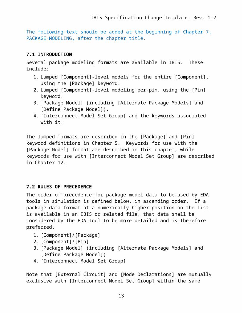
The following text should be added at the beginning of Chapter 7, PACKAGE MODELING, after the chapter title.
7.1 INTRODUCTIONSeveral package modeling formats are available in IBIS. These include:
1. Lumped [Component]-level models for the entire [Component], using the [Package] keyword.
2. Lumped [Component]-level modeling per-pin, using the [Pin] keyword.3. [Package Model] (including [Alternate Package Models] and [Define Package Model]).4. [Interconnect Model Set Group] and the keywords associated with it.
The lumped formats are described in the [Package] and [Pin] keyword definitions in Chapter 5. Keywords for use with the [Package Model] format are described in this chapter, while keywords for use with [Interconnect Model Set Group] are described in Chapter 12.
7.2 RULES OF PRECEDENCEThe order of precedence for package model data to be used by EDA tools in simulation is defined below, in ascending order. If a package data format at a numerically higher position on the list is available in an IBIS or related file, that data shall be considered by the EDA tool to be more detailed and is therefore preferred.
1. [Component]/[Package] 2. [Component]/[Pin] 3. [Package Model] (including [Alternate Package Models] and [Define Package Model])4. [Interconnect Model Set Group]
Note that [External Circuit] and [Node Declarations] are mutually exclusive with [Interconnect Model Set Group] within the same [Component]. [Package Model] and [Interconnect Model Set Group] may both be present for the same [Component] but should not both be used at the same time.
7.3 KEYWORDS FOR USE WITH [PACKAGE MODEL]
< Insert Existing Text Here>
10
IBIS Specification Change Template, Rev. 1.2
Page 141 for the [Description[ keyword, Replace:Usage Rules: The description must be less than 60 characters in length, must fit on a single line, and may contain spaces.
With:Usage Rules: The description shall fit on a single line, and may contain spaces.
11
IBIS Specification Change Template, Rev. 1.2
The following new Chapter 12 should be added after Chapter 11.
12 INTERCONNECT MODELING
12.1 INTRODUCTIONIBIS supports broadband interconnect models describing connections between the pins of a component and its I/O buffers. These interconnect models may include descriptions of frequency-dependent losses, interconnect coupling and/or complex supply rail distributions.
Interconnect is defined between up to three interface locations: pin, where a component connects to a printed circuit board die pad, where a component die connects to the routing on a package substrate buffer, where the buffer itself connects to the die substrate and routing
The relationship between the terminals at the buffer, die pad, and pin interfaces is shown in the figure below.
Buffer Terminals
Buffer Terminals PinsDie Pads
1 VCC_5.0 POWER
2 VCC_3.3 POWER
3 DATA1 DATA_MODEL
4 VSS GND
5 VCC_5.0 POWER
6 VCC_3.3 POWER
7 DATA2 DATA_MODEL
8 VSS GND
Figure 47 – Example Interconnect Model Structure
12
IBIS Specification Change Template, Rev. 1.2
The connection between the pin and die pad is generally called “package interconnect”, while the connection between the die pad and the buffer is generally called “on-die interconnect.” The die pad is distinct from the buffer terminal; the buffer includes the circuitry that would be described through the [Model] keyword and related keywords, and would not include transmission line behavior.
Interconnect models may be supplied separately for on-die interconnect and package interconnect, or may be supplied as a single model for the entire connection between the package pins and buffers.
The electrical behavior of an interconnect is described through either IBIS-ISS SPICE subcircuits or Touchstone network parameters. An Interconnect Model defines the connections to either an IBIS-ISS SPICE subcircuit or a Touchstone file. An Interconnect Model may describe the connection between the pins of the package and the buffers, the pins of the package and the die pads, or the die pads and buffers.
Interconnect Models are organized into Interconnect Model Sets. An [Interconnect Model Set] keyword consists of one or more [Interconnect Model] keywords. One Interconnect Model Set may contain groups of similar interconnect models or different interconnect models to describe the complete connections from the buffer to pin interface.
13
IBIS Specification Change Template, Rev. 1.2
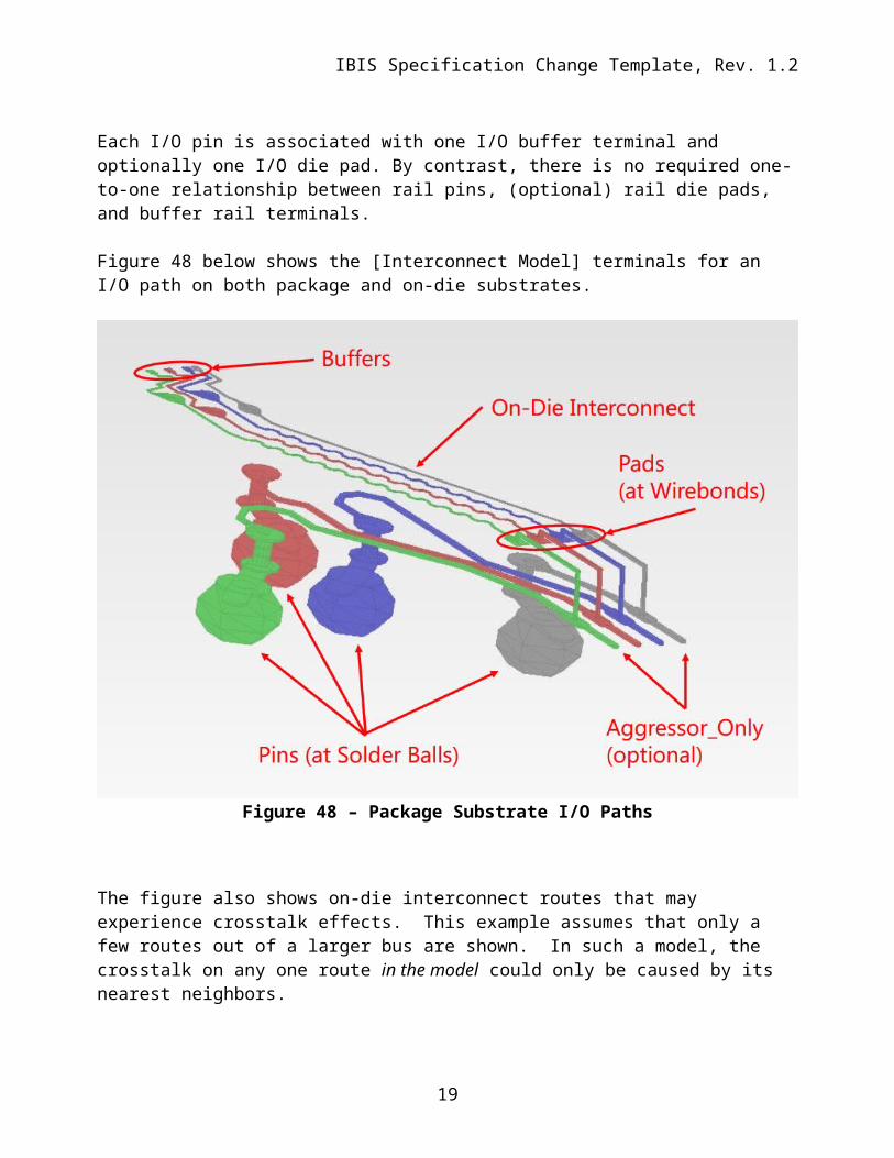
Each I/O pin is associated with one I/O buffer terminal and optionally one I/O die pad. By contrast, there is no required one-to-one relationship between rail pins, (optional) rail die pads, and buffer rail terminals.
Figure 48 below shows the [Interconnect Model] terminals for an I/O path on both package and on-die substrates.
Figure 48 – Package Substrate I/O Paths
The figure also shows on-die interconnect routes that may experience crosstalk effects. This example assumes that only a few routes out of a larger bus are shown. In such a model, the crosstalk on any one route in the model could only be caused by its nearest neighbors.
While each of the inner two routes in the figure may have all potential crosstalk represented in the model, the outer signals would not. The model maker would therefore indicate that connections to the outer routes’ terminals do not include all of their aggressors by adding the optional argument “Aggressor_Only” to their terminals. The descriptions of the associated terminals would not use the “Aggressor_Only” designation for the inner routes. The EDA tool may therefore assume in simulation that the inner routes have all (or more practically most of) the coupling to their aggressor connections represented in the model.
14
IBIS Specification Change Template, Rev. 1.2
Crosstalk simulations require Interconnect Models to have connections to multiple I/O pin_names.
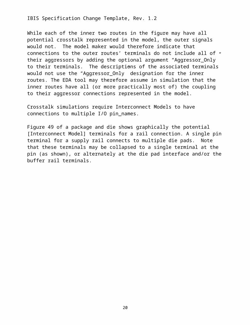
Figure 49 of a package and die shows graphically the potential [Interconnect Model] terminals for a rail connection. A single pin terminal for a supply rail connects to multiple die pads. Note that these terminals may be collapsed to a single terminal at the pin (as shown), or alternately at the die pad interface and/or the buffer rail terminals.
Figure 49 – Package Substrate Rail Terminals
The terminal section of an [Interconnect Model] describes how the terminals of an Interconnect Model subcircuit or Touchstone file instance are connected at a buffer terminal, die pad interface or pin/board interface.
12.2 GENERAL INTERCONNECT SYNTAX REQUIREMENTS
15
IBIS Specification Change Template, Rev. 1.2
Terminal lines under the [Interconnect Model] keyword describe connections.
I/O terminals shall be connected using only the pin_name qualifier at these locations: pins: I/O pin_name die pads: I/O pin_name buffer: I/O pin_name
Rail terminal connections have more options to support direct connections to terminals or to groups of terminals using signal_name, bus_label, or pad_name entries at the pin, die pad or buffer locations. For the following locations the rail terminal can connect to:
pins a specific rail pin_name all of the pins of a rail signal_name all of the pins of a bus_label
die pads all of the die pads with a rail signal_name all of the die pads with a rail bus_label a specific die pad pad_name
buffer rail terminals all of the buffer rail terminals of a rail signal_name all of the buffer rail terminals of a bus_label a specific buffer rail terminal for an I/O buffer pin_name
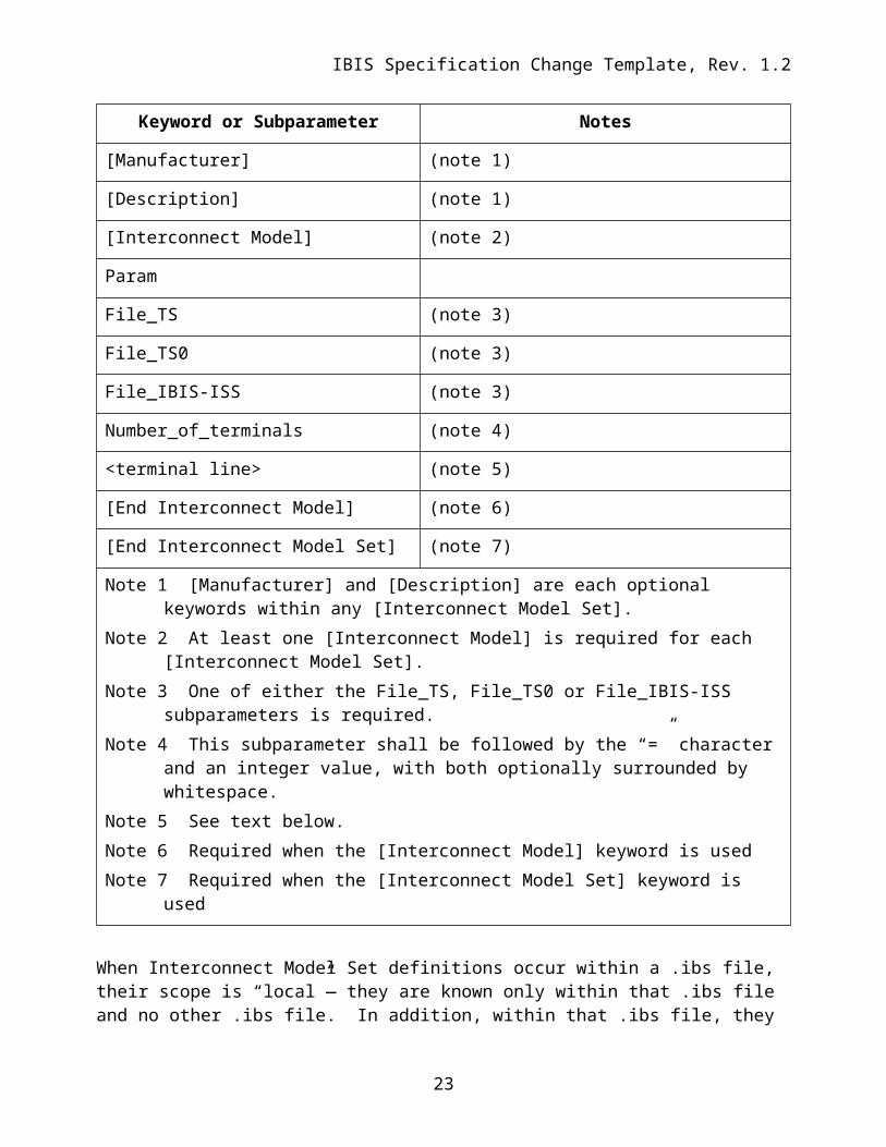
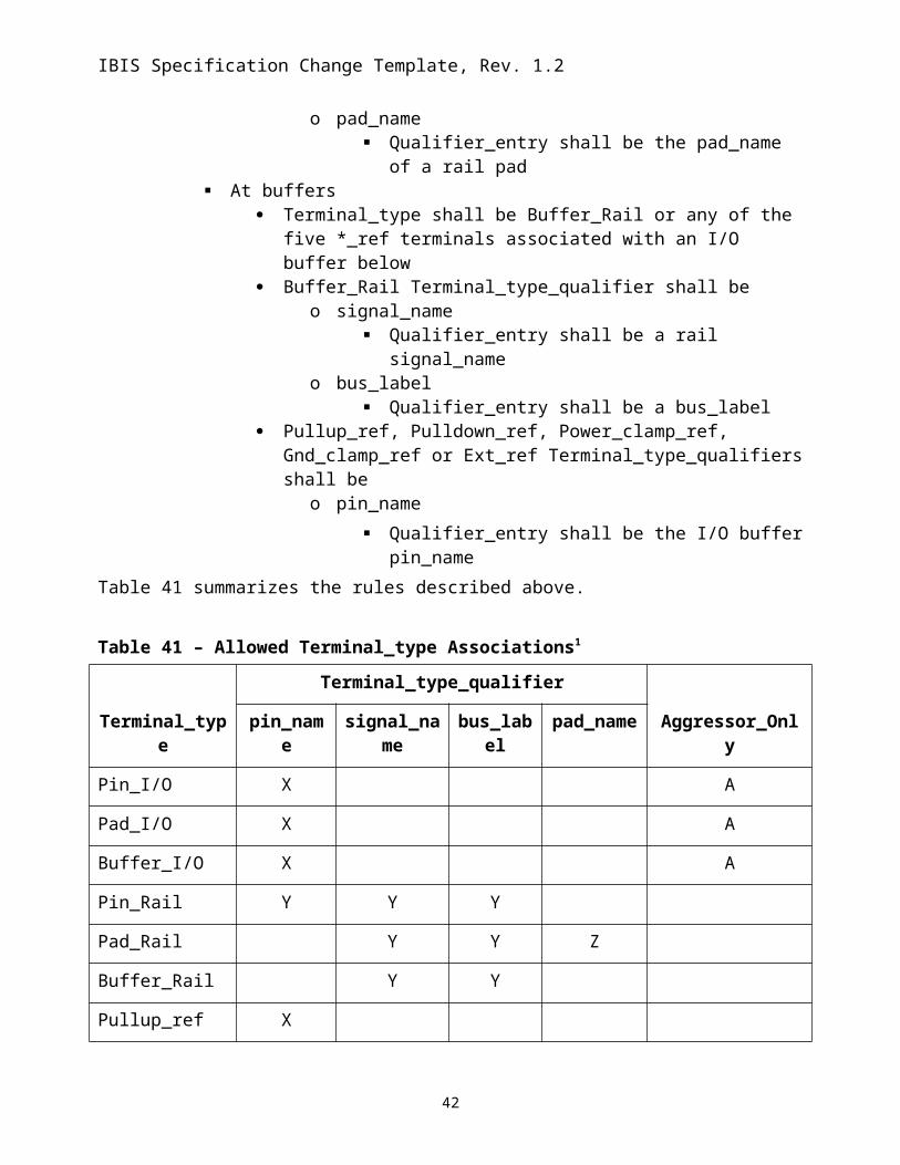
One or more Interconnect Model Sets may be included in a separate Interconnect Model Set file, using a file name with the extension “ims”, or within the .ibs file where [Interconnect Model Set Group] is used. The [Interconnect Model Set] keyword can contain the optional [Manufacturer] and [Description] keywords and one or more [Interconnect Model] keywords and the [Interconnect Model] associated subparameters, as is listed in Table 40.TableError: Reference source not found 40 – Interconnect Modeling Keywords and Subparameters
Keyword or Subparameter Notes
[Interconnect Model Set]
[Manufacturer] (note 1)
[Description] (note 1)
[Interconnect Model] (note 2)
Param
File_TS (note 3)
File_TS0 (note 3)
16
IBIS Specification Change Template, Rev. 1.2
Keyword or Subparameter Notes
File_IBIS-ISS (note 3)
Number_of_terminals (note 4)
<terminal line> (note 5)
[End Interconnect Model] (note 6)
[End Interconnect Model Set] (note 7)
Note 1 [Manufacturer] and [Description] are each optional keywords within any [Interconnect Model Set].
Note 2 At least one [Interconnect Model] is required for each [Interconnect Model Set].Note 3 One of either the File_TS, File_TS0 or File_IBIS-ISS subparameters is required.Note 4 This subparameter shall be followed by the “=” character and an integer value, with both
optionally surrounded by whitespace.Note 5 See text below.Note 6 Required when the [Interconnect Model] keyword is usedNote 7 Required when the [Interconnect Model Set] keyword is used
When Interconnect Model Set definitions occur within a .ibs file, their scope is “local”— they are known only within that .ibs file and no other .ibs file. In addition, within that .ibs file, they override any interconnect package models defined using the [Package], [Pin], or [Define Package Model] keywords. Interconnect Models in separate .ims files referenced by the [Interconnect Model Set Group] keyword in a .ibs file also override any interconnect package models defined in the same .ibs file using the [Package], [Pin], or [Define Package Model] keywords. Usage Rules for the .ims file:Interconnect models are stored in a file whose file name uses the format:
<stem>.imsThe <stem> provided shall adhere to the rules given for the [File Name] keyword. Use the “ims” extension to identify files containing Interconnect Models. The .ims file shall contain the [IBIS Ver], [File Name], [File Rev], and the [End] keywords. Optional elements include the [Date], [Source], [Notes], [Disclaimer], [Copyright], and [Comment Char] keywords. All of these keywords and associated subparameters follow the same rules as those for a normal .ibs file.Note that the [Component] and [Model] keywords are not allowed in the .ims file. The .ims file is for Interconnect Models only.
17
IBIS Specification Change Template, Rev. 1.2
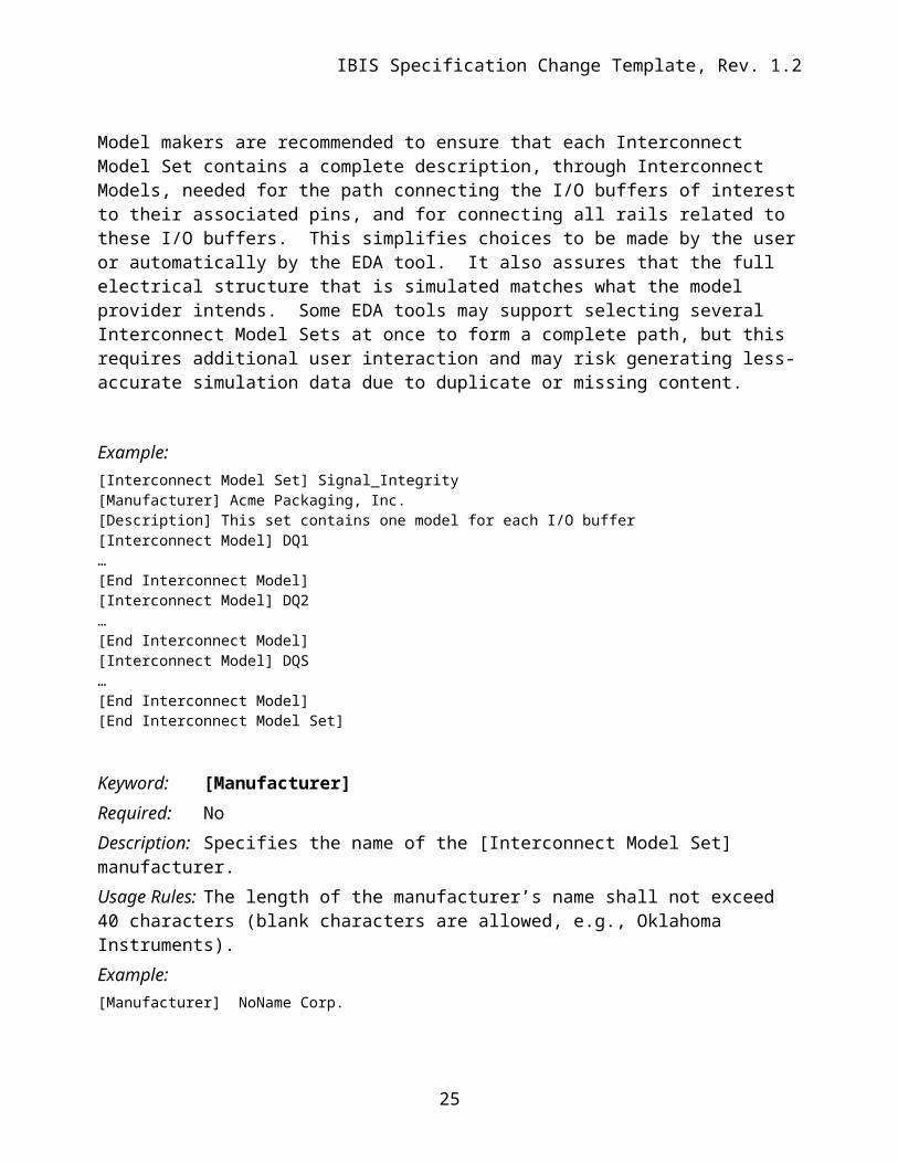
Keyword: [Interconnect Model Set]Required: NoDescription: Used to contain Interconnect ModelsUsage Rules: [Interconnect Model Set] has a single argument, which is the name of the Interconnect Model Set. The length of the Interconnect Model Set name shall not exceed 40 characters in length. Blank characters are not allowed. The [Interconnect Model Set]/[End Interconnect Model Set] keyword pair is hierarchically equivalent in scope to [Component] and [Model]. The section under the [Interconnect Model Set] keyword may contain a [Manufacturer] keyword section and [Description] keyword section and shall contain one or more Interconnect Models. See the section [Interconnect Model] for a description of the content of each Interconnect Model.
Model makers are recommended to ensure that each Interconnect Model Set contains a complete description, through Interconnect Models, needed for the path connecting the I/O buffers of interest to their associated pins, and for connecting all rails related to these I/O buffers. This simplifies choices to be made by the user or automatically by the EDA tool. It also assures that the full electrical structure that is simulated matches what the model provider intends. Some EDA tools may support selecting several Interconnect Model Sets at once to form a complete path, but this requires additional user interaction and may risk generating less-accurate simulation data due to duplicate or missing content.
Example:[Interconnect Model Set] Signal_Integrity[Manufacturer] Acme Packaging, Inc.[Description] This set contains one model for each I/O buffer[Interconnect Model] DQ1…[End Interconnect Model][Interconnect Model] DQ2…[End Interconnect Model][Interconnect Model] DQS…[End Interconnect Model][End Interconnect Model Set]
Keyword: [Manufacturer]Required: NoDescription: Specifies the name of the [Interconnect Model Set] manufacturer.Usage Rules: The length of the manufacturer’s name shall not exceed 40 characters (blank characters are allowed, e.g., Oklahoma Instruments). Example:[Manufacturer] NoName Corp.
18
IBIS Specification Change Template, Rev. 1.2
Keyword: [Description]Required: NoDescription: Provides a concise yet easily human-readable description of what kind of interconnect the [Interconnect Model Set] represents.Usage Rules: The description shall fit on a single line, and may contain spaces.Example:[Description] 220-Pin Quad Ceramic Flat Pack
Keyword: [End Interconnect Model Set]Required: Yes, for each instance of the [Interconnect Model Set] keyword.Description: Indicates the end of the Interconnect Model Set data. Example: [End Interconnect Model Set]
Keyword: [Interconnect Model]Required: NoDescription: Marks the beginning of an Interconnect Model description that is used to define the interfaces to IBIS-ISS subcircuit or Touchstone files.Sub-Params: Param, File_TS, File_TS0, File_IBIS-ISS, Number_of_terminalsUsage Rules: [Interconnect Model] has a single argument, which is the name of the associated Interconnect Model. The length of the Interconnect Model name shall not exceed 40 characters in length. Blank characters are not allowed. The [Interconnect Model]/[End Interconnect Model] keyword pair is hierarchically scoped by the [Interconnect Model Set]/[End Interconnect Model Set] keywords.
The [Interconnect Model]/[End Interconnect Model] section defines both the association between a Touchstone file or IBIS-ISS subcircuit and an Interconnect Model, as well as defining the terminals and terminal usage for the Interconnect Model in the context of the given [Component].
An [Interconnect Model] shall contain one and only one of the following combinations: pins and buffer terminals (full package model) pins and die pads (package only model) die pads and buffer terminals (on-die interconnect model)
Other Notes: If a full package model contains an I/O pin terminal for a pin_name then it shall also contain an I/O buffer terminal for the same pin_name. If a package only model contains an I/O pin
19
IBIS Specification Change Template, Rev. 1.2
terminal for a pin_name then it shall also contain an I/O die pad for the same pin_name. If an on-die interconnect model contains an I/O buffer terminal for a pin_name then it shall also contain an I/O die pad for the same pin_name.
An [Interconnect Model] may contain: only power rail models one or more I/O signal models both power rail models and one or more I/O signal models
Each terminal of an Interconnect Model is connected to a node and has a “voltage”. This, as stated, is imprecise. Voltage, by definition, is a potential difference between two points. It is common to probe and plot the potential difference between simulator nodes at a terminal and the simulator ideal Node 0. This is valid for non-power aware simulations when the local ground (or return path) node is forced to Node 0 by the simulator, or for “ground referenced” power aware simulations that lump the effect of the ground interconnect into the power rails. However, this is not valid when the local ground nodes are “floating”. In this case it is important that the actual rail node that is the reference node for measurements at the I/O buffer is included as a terminal in the Interconnect Model. If this is not done, then the Interconnect Model will not correctly account for all return currents, particularly from capacitive elements. If an Interconnect Model does not contain a reference terminal, then the user of these models should be aware that using these models in non-ground referenced power aware simulations will introduce potential errors in simulations.
The following subparameters are defined:ParamFile_IBIS-ISSFile_TSFile_TS0Number_of_terminals = <value>
In addition to these subparameters, the [Interconnect Model]/[End Interconnect Model] section may contain lines describing terminals and their connections. No specific subparameter name, token, or other string is used to identify terminal lines.
Unless noted below, no Interconnect Model subparameter requires the presence of any other subparameter.
Param rules:The subparameter Param is optional and only legal with the File_IBIS-ISS subparameter documented below. Param is illegal with the File_TS or File_TS0 subparameter documented below. Param shall be followed by three arguments: an unquoted string argument giving the name of the parameter to be passed into the IBIS-ISS subcircuit, a reserved word for the parameter format, and one numerical value or one string value
20
IBIS Specification Change Template, Rev. 1.2
(surrounded by double quotes) for the parameter value to be passed into the IBIS-ISS subcircuit.
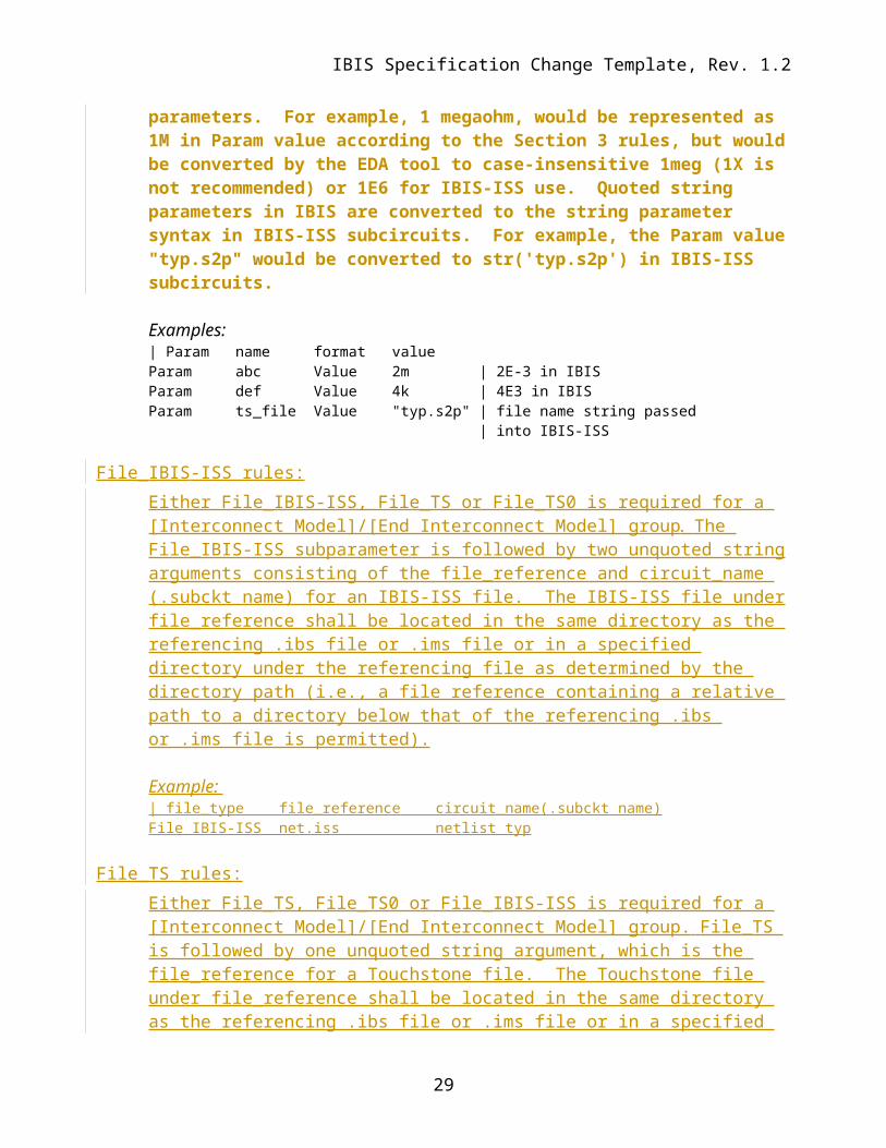
The numerical value rules follow the scaling conventions in Section 3.2, “SYNTAX RULES”. The EDA tool is responsible for translating IBIS specified parameters into IBIS-ISS parameters. For example, 1 megaohm, would be represented as 1M in Param value according to the Section 3 rules, but would be converted by the EDA tool to case-insensitive 1meg (1X is not recommended) or 1E6 for IBIS-ISS use. Quoted string parameters in IBIS are converted to the string parameter syntax in IBIS-ISS subcircuits. For example, the Param value "typ.s2p" would be converted to str('typ.s2p') in IBIS-ISS subcircuits.
Examples: | Param name format valueParam abc Value 2m | 2E-3 in IBISParam def Value 4k | 4E3 in IBIS Param ts_file Value "typ.s2p" | file name string passed | into IBIS-ISS
File_IBIS-ISS rules:Either File_IBIS-ISS, File_TS or File_TS0 is required for a [Interconnect Model]/[End Interconnect Model] group. The File_IBIS-ISS subparameter is followed by two unquoted string arguments consisting of the file_reference and circuit_name (.subckt name) for an IBIS-ISS file. The IBIS-ISS file under file_reference shall be located in the same directory as the referencing .ibs file or .ims file or in a specified directory under the referencing file as determined by the directory path (i.e., a file reference containing a relative path to a directory below that of the referencing .ibs or .ims file is permitted).
File_TS rules:Either File_TS, File_TS0 or File_IBIS-ISS is required for a [Interconnect Model]/[End Interconnect Model] group. File_TS is followed by one unquoted string argument, which is the file_reference for a Touchstone file. The Touchstone file under file_reference shall be located in the same directory as the referencing .ibs file or .ims file or in a specified directory under the referencing file as determined by the directory path (i.e., a file reference containing a relative path to a directory below that of the referencing .ibs or .ims file is permitted).
File_TS0 rules:Either File_TS, File_TS0 or File_IBIS-ISS is required for a [Interconnect Model]/[End Interconnect Model] group. File_TS0 is followed by one unquoted string argument, which is the file_reference for a Touchstone file. The Touchstone file under file_reference shall be located in the same directory as the referencing .ibs file or .ims file or in a specified directory under the referencing file as determined by the directory path (i.e., a file reference containing a relative path to a directory below that of the referencing .ibs or .ims file is permitted).
Number_of_terminals rules: The Number_of_terminals subparameter is required and defines the number of terminals associated with the Interconnect Model. The subparameter name shall be followed by a single integer argument on the same line. The argument shall be separated from the subparameter name by the “=” character. The subparameter name, “=” character, and argument may optionally be separated by whitespace.
Only one Number_of_terminals subparameter may appear for a given [Interconnect Model] keyword. The Number_of_terminals subparameter shall appear before any terminal lines and after all other subparameters for a given Interconnect Model.
For File_IBIS-ISS, the Number_of_terminals value shall be equal to the number of subcircuit terminals for an IBIS-ISS subcircuit. Because an IBIS-ISS subcircuit requires at least one terminal the Number_of_ports value shall be 1 or greater.
For File_TS, the Number_of_terminals value shall be a value equal to N+1 (number of ports plus one) in the Touchstone file. Because a Touchstone file requires at least one port, the Number_of_terminals value shall be 2 or greater.
For File_TS0, the Number_of_terminals value shall be a value equal to N (number of ports) in the Touchstone file. Because a Touchstone file requires at least one port, the Number_of_Terminals value shall be 1 or greater.
Example:Number_of_terminals = 3
Terminal line rules: The terminal lines shall appear after the Number_of_terminals subparameter and before the [End Interconnect Model] keyword.
Terminal lines are of the following form, with each identifier separated by whitespace:
Terminal_numberThe Terminal_number is the identifier for a specific terminal. The value shall be 1 or greater and less than or equal to the Number_of_terminals. The same Terminal_number shall not appear more than once for a given Interconnect Model.
For File_IBIS-ISS, the Terminal_number entry shall match the IBIS-ISS terminal (node) position. The Terminal_number entries may be listed in any order as long as there are no duplicate entries. Each IBIS-ISS terminal shall have terminal line entry
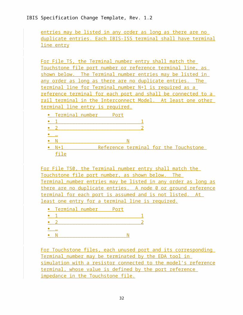
For File_TS, the Terminal_number entry shall match the Touchstone file port number or reference terminal line, as shown below. The Terminal_number entries may be listed in any order as long as there are no duplicate entries. The terminal line for Terminal_number N+1 is required as a reference terminal for each port and shall be connected to a rail terminal in the Interconnect Model. At least one other terminal line entry is required.
Terminal_number Port 1 1 2 2 … N N N+1 Reference terminal for the Touchstone file
For File_TS0, the Terminal_number entry shall match the Touchstone file port number, as shown below. The Terminal_number entries may be listed in any order as long as there are no duplicate entries. A node 0 or ground reference terminal for each port is assumed and is not listed. At least one entry for a terminal line is required.
Terminal_number Port 1 1 2 2 … N N
For Touchstone files, each unused port and its corresponding Terminal_number may be terminated by the EDA tool in simulation with a resistor connected to the model’s reference terminal, whose value is defined by the port reference impedance in the Touchstone file.
File_IBIS-ISS rules:Either File_IBIS-ISS, File_TS or File_TS0 is required for a [Interconnect Model]/[End Interconnect Model] group. The File_IBIS-ISS subparameter is followed by two unquoted string arguments consisting of the file_reference and circuit_name (.subckt name) for an IBIS-ISS file. The IBIS-ISS file under file_reference shall be located in the same directory as the referencing .ibs file or .ims file or in a specified directory under the referencing file as determined by the directory path (i.e., a file reference containing a relative path to a directory below that of the referencing .ibs or .ims file is permitted).
23
Author, 01/03/-1,
Radek suggests “may” be replaced with something definite.
Author, 01/03/-1,
Radek suggests defaulting to open, with a directive for termination using port reference impedance.
File_TS rules:Either File_TS, File_TS0 or File_IBIS-ISS is required for a [Interconnect Model]/[End Interconnect Model] group. File_TS is followed by one unquoted string argument, which is the file reference for a Touchstone file. The Touchstone file under file_reference shall be located in the same directory as the referencing .ibs file or .ims file or in a specified directory under the referencing file as determined by the directory path (i.e., a file reference containing a relative path to a directory below that of the referencing .ibs or .ims file is permitted).). File_TS models require that there be a Terminal record for the reference for all ports.
File_TS0 rules:Either File_TS, File_TS0 or File_IBIS-ISS is required for a [Interconnect Model]/[End Interconnect Model] group. File_TS0 is followed by one unquoted string argument, which is the file reference for a Touchstone file. The Touchstone file under file_reference shall be located in the same directory as the referencing .ibs file or .ims file or in a specified directory under the referencing file as determined by the directory path (i.e., a file reference containing a relative path to a directory below that of the referencing .ibs or .ims file is permitted).). File_TS models assume that Node 0 be used for the reference for all ports.
Number_of_terminals rules: The Number_of_terminals subparameter is required and defines the number of terminals associated with the Interconnect Model. The subparameter name shall be followed by a single integer argument. greater than zero on the same line. The argument shall be separated from the subparameter name by the “=” character. The subparameter name, “=” character, and argument may optionally be separated by whitespace.
Only one Number_of_terminals subparameter may appear for a given [Interconnect Model] keyword. The Number_of_terminals subparameter shall appear before any terminal lines and after all other subparameters for a given Interconnect Model.
For File_IBIS-ISS, the Number_of_terminals . The value shall be 1 or greater and equal the number of subcircuit terminals for an IBIS-ISS subcircuit.
24
IBIS Specification Change Template, Rev. 1.2
For File_TS, the th The Number_of_terminals value shall be 2 or greater and equal to the number of ports N plus 1 (N+1) in the Touchstone filefor File_TS models.
For File_TS0, t The Number_of_terminals value shall be 1 or greater and equal tobe the number of ports (N) in the Ttouchstone file.for File_TS0 models. The subparameter name shall be followed by a single integer argument greater than zero on the same line. The argument shall be separated from the subparameter name by the “=” character. The subparameter name, “=” character, and argument may optionally be separated by whitespace. Only one Number_of_terminals subparameter may appear for a given [Interconnect Model] keyword. The Number_of_terminals subparameter shall appear before any terminal lines and after all other subparameters for a given Interconnect Model.
Example:Number_of_terminals = 3
Terminal line rules: The Terminal lines shall appear after the Number_of_terminals subparameter and before the [End Interconnect Model] keyword.. No token or reserved word identifies terminal lines.
Each terminal line contains information on a terminal of an IBIS-ISS subcircuit (or Touchstone file).For File_IBIS-ISS Interconnect Models, each terminalnodeterminal present in the IBIS-ISS subcircuit definition shall have a corresponding terminal line.
For File_TS ort File_TS0 Interconnect Models, it is not necessary to list each port on a corresponding terminal line under the [Interconnect Model] keyword. Such unused ports may be terminated by the EDA tool in simulation with a resistor connected to the model’s reference terminal, whose value is defined by the port reference impedance in the Touchstone file.Terminal lines are of the following form, with each identifier separated by whitespace::
Terminal_numberThe Terminal_number is thean iTerminal_number is an identifier for a specific terminal. The Terminal_number shall be a positive non-zero integer less than or equal to the value of the Number_of_terminals argument. Theis value shall be 1 or greater and than zero and less than or equal to the Number_of_terminals. The same Terminal_number shall not appear more than once for a given Interconnect Model.
For File_IBIS-ISS, tThe Terminal_number entry shall match the IBIS-ISS terminal (node) position. The Terminal_number entries may be listed in any order as long as there are no duplicate entries. At least one entry for a Terminal_line is required
25
Author, 01/03/-1,
Radek suggests defaulting to open, with a directive for termination using port reference impedance.
Author, 01/03/-1,
Mike L. suggests deleting “by the EDA tool”.
Author, 01/03/-1,
Radek suggests “may” be replaced with something definite.
IBIS Specification Change Template, Rev. 1.2
For File_TS, the Terminal_number shall match the or the Touchstone file terminal (portline) position, plus an undeclared reference line, as shown below.. The Terminal_number entries may be listed in any order as long as there are no duplicate entries. The Terminal line for Terminal_number N+1 is required as a reference for each port and shall beto connectedct to a rail terminal in the [Interconnect Model]]. At least one plus an entry for at least one other Terminal_line entry is required...
Terminal_number Port 1 1 2 2 … N N N+1 reference
For File_TS0, the Terminal_number shall match the the Touchstone file terminal (port) position, as shown below.. The Terminal_number entries may be listed in any order as long as there are no duplicate entries. A node 0 or ground reference for each port reference is assumed and is not listed. At least, one entry for a Terminal_line is required.
Terminal_number Port 1 1 2 2 … N N N+1 reference
For Touchstone filess, each unused port and its corresponding Terminal_number may be terminated by the EDA tool in simulation with a resistor connected to the model’s reference terminal, whose value is defined by the port reference impedance in the Touchstone file.
Terminal_typeThe TTerminal_type is a string that identifies whether the terminal is a supply or I/O terminal and whether the terminal is connected at the buffer, die pad, or pin level. (N(note that “I/O” in this context is a synonym for “signal”, as opposed to “supply” or “”rail”; it is not intended to imply model type as used in the “Model_type” subparameter). Furthermore, if the terminal is connected to a buffer supply rail, the Terminal_type identifies to which specific buffer rail the terminal is connected. The Terminal_type shall be one of the following:
Pin_I/O Pad_I/O Buffer_I/O
26
Author, 01/03/-1,
Radek suggests defaulting to open, with a directive for termination using port reference impedance.
Author, 01/03/-1,
Mike L. suggests deleting “by the EDA tool”.
Author, 01/03/-1,
Radek suggests “may” be replaced with something definite.
Buffer_I/O, Pullup_ref, Pulldown_ref, Power_clamp_ref, Gnd_clamp_ref, Ext_ref and Buffer_Rail are terminals of an Interconnect Model that connect directly to I/O buffers. Pad_I/O and Pad_Rail are terminals that are at the die pad interface.Pin_I/O and Pin_Rail are terminals that are at the pin interface that can connect the package to the PCB.
The Terminal_types Buffer_I/O, Pad_I/O and Pin_I/O are used only for any single terminal of a buffer described by the [Model] keyword and for any Model_type subparameter listed in Section 5, Table 1. The Model_types Series and *_diff are used for two-terminal configurations, and their terminals require two separate Buffer_I/O, Pad_I/O or Pin_I/O Terminal_type lines.
Terminal_type_qualifier The Terminal_type_qualifier is a string that identifies the association between a terminal and a specific pin_name, signal_name, bus_label, or pad_name. Only certain Terminal_types may be used with pad_names, pin_names, signal_names, or bus_labels respectively, as outlined in the Connecting Pins, Pads, and Buffer Terminals section below and summarized in Table 41.
Qualifier_entry The <Qualifier_entry>, shown in angle brackets, is the name required for the following Terminal_type_qualifiers:
Aggressor_OnlyThe Aggressor_Only entry is optional and is indicated by the string “Aggressor_Only” without the quotation marks.
27
IBIS Specification Change Template, Rev. 1.2
Multi-line models may describe only a subset of a coupled structure (e.g., a 64-line bus may be described by a four-line model). As a result, while the interconnects at the edges of the model may induce crosstalk onto other interconnects nearby, being on the edge of the model, they may not themselves experience the full crosstalk impact that the corresponding interconnect experiences in the real, full structure. The optional Aggressor_Only column entry is allowed on all terminal locations for I/O terminals to indicate such incomplete coupling. Terminals that include the Aggressor_Only entry may not be suitable to be simulated as victims, as they do not experience the full coupling present in the real physical structure. If an I/O terminal is not identified as Aggressor_Only, then the interconnect to that I/O terminal includes coupling to all interconnections deemed necessary for coupled signal analysis. If a particular terminal is identified as Aggressor_Only, then the entire path of the associated pin_name is to be considered Aggressor_Only.
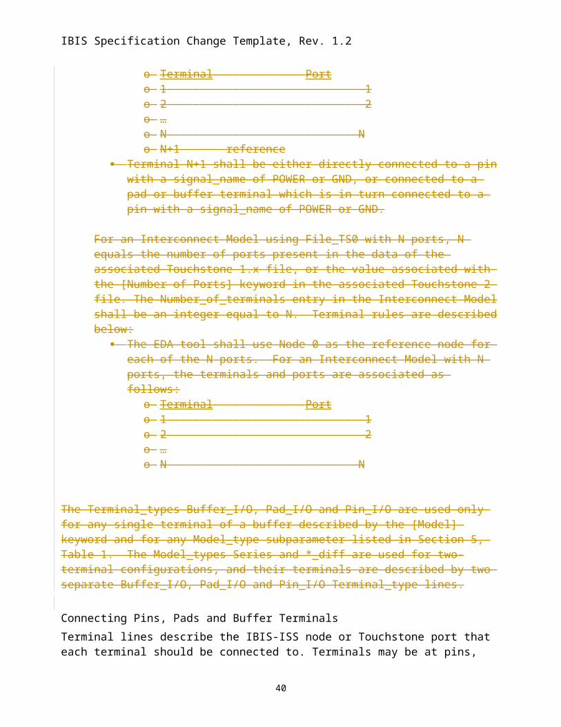
Touchstone FilesFor an Interconnect Model using File_TS with N ports, N equals the number of ports present in the data of the associated Touchstone 1.x file, or the value associated with the [Number of Ports] keyword in the associated Touchstone 2 file. The Number_of_terminals entry in the Interconnect Model shall be an integer equal to N+1. Terminal rules are described below:
The EDA tool shall use the pin_name or signal_name specified for the associated terminal “N+1” entry as the reference node for each of the N ports. For an Interconnect Model with N ports, the terminals and ports are associated as follows:
o Terminal Porto 1 1o 2 2o …o N No N+1 reference
Terminal N+1 shall be either directly connected to a pin with a signal_name of POWER or GND, or connected to a pad or buffer terminal which is in turn connected to a pin with a signal_name of POWER or GND.
For an Interconnect Model using File_TS0 with N ports, N equals the number of ports present in the data of the associated Touchstone 1.x file, or the value associated with the [Number of Ports] keyword in the associated Touchstone 2 file. The Number_of_terminals entry in the Interconnect Model shall be an integer equal to N. Terminal rules are described below:
The EDA tool shall use Node 0 as the reference node for each of the N ports. For an Interconnect Model with N ports, the terminals and ports are associated as follows:
o Terminal Porto 1 1o 2 2o …o N N
28
IBIS Specification Change Template, Rev. 1.2
The Terminal_types Buffer_I/O, Pad_I/O and Pin_I/O are used only for any single terminal of a buffer described by the [Model] keyword and for any Model_type subparameter listed in Section 5, Table 1. The Model_types Series and *_diff are used for two-terminal configurations, and their terminals are described by two separate Buffer_I/O, Pad_I/O and Pin_I/O Terminal_type lines.
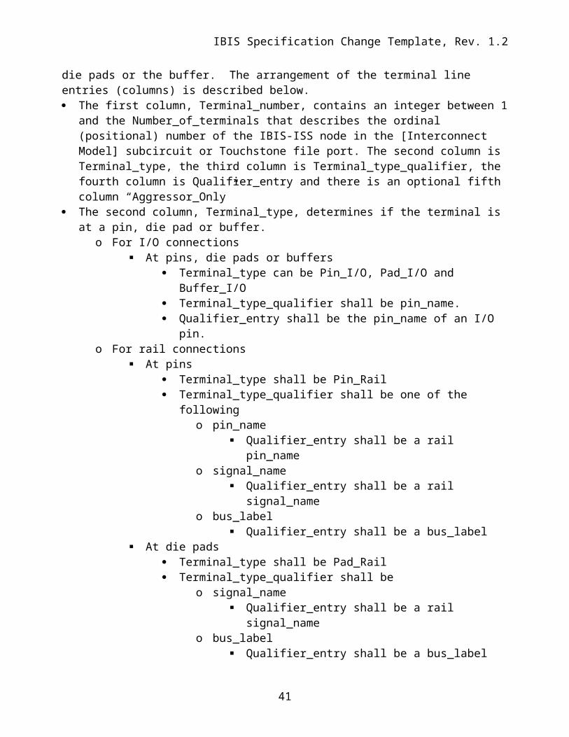
Connecting Pins, Pads and Buffer TerminalsTerminal lines describe the IBIS-ISS node or Touchstone port that each terminal should be connected to. Terminals may be at pins, die pads or the buffer. The arrangement of the terminal line entries (columns) is described below. The first column, Terminal_number, contains an integer between 1 and the
Number_of_terminals that describes the ordinal (positional) number of the IBIS-ISS node in the [Interconnect Model] subcircuit or Touchstone file port. The second column is Terminal_type, the third column is Terminal_type_qualifier, the fourth column is Qualifier_entry and there is an optional fifth column “Aggressor_Only”
The second column, Terminal_type, determines if the terminal is at a pin, die pad or buffer.o For I/O connections
At pins, die pads or buffers Terminal_type can be Pin_I/O, Pad_I/O and Buffer_I/O Terminal_type_qualifier shall be pin_name. Qualifier_entry shall be the pin_name of an I/O pin.
o For rail connections At pins
Terminal_type shall be Pin_Rail Terminal_type_qualifier shall be one of the following
o pin_name Qualifier_entry shall be a rail pin_name
o signal_name Qualifier_entry shall be a rail signal_name
o bus_label Qualifier_entry shall be a bus_label
At die pads Terminal_type shall be Pad_Rail Terminal_type_qualifier shall be
o signal_name Qualifier_entry shall be a rail signal_name
o bus_label Qualifier_entry shall be a bus_label
o pad_name Qualifier_entry shall be the pad_name of a rail pad
At buffers Terminal_type shall be Buffer_Rail or any of the five *_ref terminals
associated with an I/O buffer below Buffer_Rail Terminal_type_qualifier shall be
29
IBIS Specification Change Template, Rev. 1.2
o signal_name Qualifier_entry shall be a rail signal_name
o bus_label Qualifier_entry shall be a bus_label
Pullup_ref, Pulldown_ref, Power_clamp_ref, Gnd_clamp_ref or Ext_ref Terminal_type_qualifiers shall be
o pin_name Qualifier_entry shall be the I/O buffer pin_name
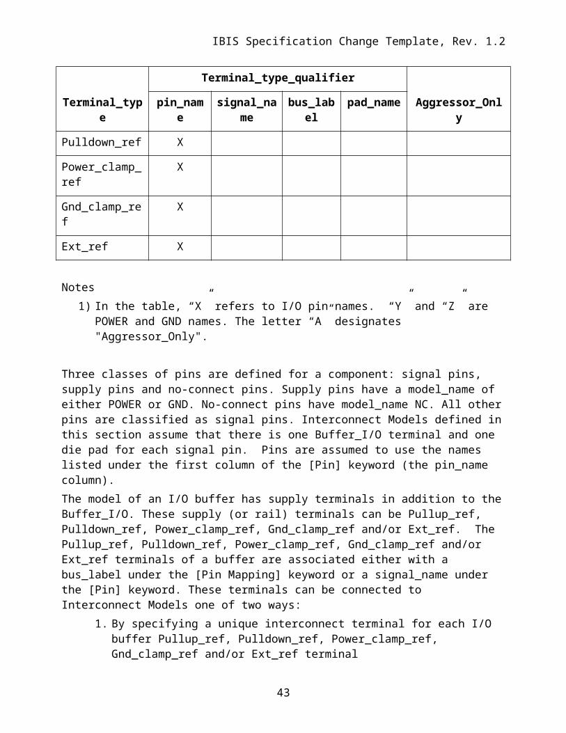
Notes1) In the table, “X” refers to I/O pin names. “Y” and “Z” are POWER and GND names. The
letter “A” designates "Aggressor_Only".
Three classes of pins are defined for a component: signal pins, supply pins and no-connect pins. Supply pins have a model_name of either POWER or GND. No-connect pins have model_name NC. All other pins are classified as signal pins. Interconnect Models defined in this section assume that there is one Buffer_I/O terminal and one die pad for each signal pin. Pins are assumed to use the names listed under the first column of the [Pin] keyword (the pin_name column).
30
IBIS Specification Change Template, Rev. 1.2
The model of an I/O buffer has supply terminals in addition to the Buffer_I/O. These supply (or rail) terminals can be Pullup_ref, Pulldown_ref, Power_clamp_ref, Gnd_clamp_ref and/or Ext_ref. The Pullup_ref, Pulldown_ref, Power_clamp_ref, Gnd_clamp_ref and/or Ext_ref terminals of a buffer are associated either with a bus_label under the [Pin Mapping] keyword or a signal_name under the [Pin] keyword. These terminals can be connected to Interconnect Models one of two ways:
1. By specifying a unique interconnect terminal for each I/O buffer Pullup_ref, Pulldown_ref, Power_clamp_ref, Gnd_clamp_ref and/or Ext_ref terminal
2. By assuming that all I/O buffer supply terminals connected to a supply signal_name or bus_label are shorted together. This is done by specifying a unique terminal (of Terminal_type Buffer_Rail) for all I/O buffer terminals that are connected to a specific signal_name or bus_label on at least one supply pin.
Pads are the location of the interface between the die and the package (also called the die pad interface). Interconnect Models can either be between the pins of a component and the I/O buffers, or they can be split into models between the pins of a component and the pads of the die and models between the pads of the die and the I/O buffers. There is exactly one Pad (of Terminal_type Pad_I/O) for each signal pin. There can be any number of pads (of Terminal_type Pad_Rail) for each signal_name or bus_label on supply pins. If Interconnect Models of supply (rail) networks are split between Pin/Pad and Pad/Buffer models, then the interface of supply connections at the die pad interface can be handled in one of two ways:
1. By defining a list of die supply pads, and specifying terminals for some or all of the die supply pads that are connected to a bus_label or signal_name on at least one supply pin.
2. By assuming that all supply pads connected to a supply signal_name or bus_label are shorted together. This is done by specifying a unique terminal (of Terminal_type Pad_Rail) for all pads that are connected to a specific signal_name on at least one supply pin.
Pins may be terminals of the Interconnect Model that connect directly to a printed circuit board or other type of system connection to an IBIS component. Pins can be signal pins (Pin_I/O), or supply pins (Pin_Rail). An Interconnect Model can connect supply pins in one of two ways:
1. By specifying terminals for some or all of the supply pins.2. By assuming that all supply pins connected to a supply signal_name or bus_label are
shorted together. This is done by specifying a unique terminal (of Terminal_type Pin_Rail) for all pins that are connected to a specific signal_name on at least one supply pin.
The terminals of an Interconnect Model may be located at pins and die pads, pins and buffers, or die pads and buffers. A single Interconnect Model shall not have terminals at pins, die pads and buffers simultaneously.
Any one pin name shall not be included in more than one terminal of an Interconnect Model.Any one die pad name shall not be included in more than one terminal of an Interconnect Model.Any one buffer terminal name shall not be included in more than one terminal of an Interconnect Model.
31
IBIS Specification Change Template, Rev. 1.2
Examples:
| All examples show a [Interconnect Model Set] for grouping of the| [Interconnect Model] descriptions that can be referenced|| Naming convention for [Interconnect Model Set] examples is below| ([Interconnect Model] may show additional details)|| Full – Includes all I/O pins| A1 or A1_A3 – Designated pin or pins| TS - Touchstone representation| ISS - IBIS-ISS representation| PDN - Includes power delivery network, can also be PU and PD| IO - Only if modified differently than PDN below for buf_pad_pin| buf_pad_pin – Includes models for buf_pad, pad_pin; if missing, buf_pad| sn - Uses signal_name; if missing assumes pin_name| bl - Uses bus_label; if missing assumes pin_name| pn - Uses pad_name; if missing assumes pin_name| XTALK - Cross talk analysis (coupled nets may include Aggressor_Only)
| Examples 1 – 11 apply to the configuration below:
| Example 2: Same as Example 1 except the PDN networks are simplified with| signal_name qualifiers to create a pair of POWER terminals and a pair| of GND terminals
[Interconnect Model Set] Full_ISS_PDN_sn_2|-----[Interconnect Model] Full_ISS_buf_pin_2File_IBIS-ISS full_buf_pin.iss full_buf_pin_2_typNumber_of_terminals = 14
| Example 3: Single I/O Touchstone connection with one extra terminal for the| N+1 .s2p reference connection terminal; [Interconnect Model Set] keyword| stored in touchstone/ts_sets.ims
[Interconnect Model Set] A1_TS|-----[Interconnect Model] A1_TS_buf_pinFile_TS dq_ts_buf_pin.s2pNumber_of_terminals = 31 Pin_I/O pin_name A12 Buffer_I/O pin_name A13 Pulldown_ref pin_name A1 | VSS reference for .s2p file | Rail connections to Buffer_I/O through | [Pin Mapping] or a [Model] reference | voltage used if no external rails
36
IBIS Specification Change Template, Rev. 1.2
[End Interconnect Model][End Interconnect Model Set] |******************************************************************************
| Example 4: Single I/O pin documenting both IBIS-ISS and Touchstone files and| showing that the File_TS Touchstone N+1 reference connection is to the VSS| rail and the File_TS0 Touchstone has no reference connection in three| in three [Interconnect Model Set]s
[Interconnect Model Set] A1_TS_pad_pin|-----[Interconnect Model] A1_TS_pad_pinFile_TS dq_ts_pad_pin.s2pNumber_of_terminals = 31 Pin_I/O pin_name A12 Pad_I/O pin_name A13 Pin_Rail signal_name VSS | VSS is reference for .s2p file| | Requires Pin_Rail VSS connection[End Interconnect Model] [End Interconnect Model Set]
[Interconnect Model Set] A1_TS_pad_pin|-----[Interconnect Model] A1_TS_pad_pinFile_TS0 dq_ts_pad_pin.s2pNumber_of_terminals = 31 Pin_I/O pin_name A12 Pad_I/O pin_name A1| | Reference is assumed to be Node 0[End Interconnect Model] [End Interconnect Model Set]
[Interconnect Model Set] A1_ISS_buf_pad|-----[Interconnect Model] A1_ISS_buf_padFile_IBIS-ISS dq_iss_buf_pad.iss DQ_buf_pad_typNumber_of_terminals = 31 Pad_I/O pin_name A12 Buffer_I/O pin_name A13 Pulldown_ref pin_name A1 | A reference terminal for ISS paths|| [Pin Mapping] connections used to connect external rails; or default| internal [Model] rails used if no external rails|[End Interconnect Model][End Interconnect Model Set]
| As an alternative formulation, the [Interconnect Model]s in two| Interconnect Model Set]s could be combined into one [Interconnect Model| Set] describing the full connection of A1 from buffer to pin|
| Example 8: Same full IBIS-ISS model with PDN as in Example 7, but with the| [Interconnect Model]s describing buf_pad and pad_pin connections| separately
| Example 9: Same full IBIS-ISS configuration with PDN as in Example 8, except| that I/O connections are direct from buf_pin while the PDN connections are| from buf_pad and pad_pin using the signal_name qualifier
| Example 10: Terminals A1_A3 set up for and IBIS-ISS connections with coupling| for cross-talk analysis – Aggressor_Only terminals at the Buffer are | designated
[Interconnect Model Set] A1_A3_DQ_TS_XTALK|-----[Interconnect Model] A1_A3_DQ_TS_buf_pin_XTALKFile_TS dq_iss_buf_pin_xtalk.s6pNumber_of_terminals = 7
| The EDA tool connects the terminals and pins as follows:|| 1 Pins P1 and P2| 2 Pins G1 and G2| 3 Pullup_ref of buffers A1 and A2| 4 Pullup_ref of buffers A3 and A4| 5 Pulldown_ref of buffers A1, A2, A3 and A4
Required: Yes, for each instance of the [Interconnect Model] keywordDescription: Indicates the end of the Interconnect Model data. Example: [End Interconnect Model]
45
IBIS Specification Change Template, Rev. 1.2
The following paragraph under the [Description] keyword for [Define Package Model] on page 141:Usage Rules: The description must be less than 60 characters in length, must fit on a single line, and may contain spaces.
should be replaced with:Usage Rules: The description shall fit on a single line, and may contain spaces.