200
IBM BigFix OS Deployment V3.9 User's Guide IBM
| Date post: | 05-Jan-2017 |
| Category: |
Documents |
| Upload: | nguyenngoc |
| View: | 446 times |
| Download: | 52 times |
IBM BigFix
OS Deployment V3.9 User's Guide
IBM


IBM BigFix
OS Deployment V3.9 User's Guide
IBM

NoteBefore using this information and the product it supports, read the information in “Notices” on page 189.

Contents
Chapter 1. Product overview . . . . . . 1Understanding BigFix OS Deployment componentsand terminology . . . . . . . . . . . . . 2What's new in version 3.9 . . . . . . . . . . 7Features added in previous versions . . . . . . 8System requirements . . . . . . . . . . . 13Process overview . . . . . . . . . . . . 15Enable OS Deployment and Bare Metal Imaging site 16Navigation tree overview. . . . . . . . . . 17
Chapter 2. Configuring the OSDeployment Environment. . . . . . . 19Install BES Server Plugin Service . . . . . . . 20Install or Upgrade Upload Maintenance Service . . 20Update Server Whitelist for OS Deployment . . . 21Managing the Linux Image provider . . . . . . 21Managing Bare Metal OS Deployment Servers . . . 22Ports used by the Bare Metal OS Deployment Server 25Configuring the DHCP server . . . . . . . . 26Deploying the Management Extender for Bare MetalTargets . . . . . . . . . . . . . . . . 28Activating Analyses . . . . . . . . . . . 30
SSL Encryption Analysis for OS Deployment . . 30OS Deployment Server Information . . . . . 31Re-image Failure Information . . . . . . . 31Hardware Information. . . . . . . . . . 32Bundle Creator Machine Information . . . . . 32Bare Metal Target information . . . . . . . 33
Health Checks Dashboard . . . . . . . . . 33Enable Encryption for Clients . . . . . . . . 35Verifying Secure Hash Algorithm (SHA-256)readiness . . . . . . . . . . . . . . . 35
Chapter 3. Managing MDT Bundles andDeployment Media for Windows targets 37Bundle and Media Manager Dashboard . . . . . 37
Installing MDT Bundle Creators . . . . . . 38Creating and uploading MDT Bundles . . . . 42Creating Windows Deployment Media . . . . 43
Creating and managing MDT bundles manually . . 48MDT Bundle creation process . . . . . . . 49Prerequisites . . . . . . . . . . . . . 50MDT Bundle Creation Options . . . . . . . 52Uploading MDT Bundles . . . . . . . . . 55
Troubleshooting MDT Bundle process errors . . . 56
Chapter 4. Managing Drivers forWindows Deployments . . . . . . . . 59Preparing drivers for Windows deployments . . . 61Importing and managing drivers for Windowsdeployments . . . . . . . . . . . . . . 61Managing Windows driver bindings . . . . . . 68Checking driver availability . . . . . . . . . 70
Chapter 5. Managing Linux OSResources and Deployment Media . . . 73
Chapter 6. Managing Images . . . . . 75Capturing Windows Images . . . . . . . . . 75
Specify SMB Share Information . . . . . . . 77Choosing Capture Options . . . . . . . . 77
Capturing Linux images . . . . . . . . . . 79Importing images . . . . . . . . . . . . 80
Chapter 7. Reimaging . . . . . . . . 85Reimaging Windows Systems . . . . . . . . 86
Deploying an image to a target computer . . . 88Reimaging Windows Systems in multicast . . . 102
Reimaging Linux Systems . . . . . . . . . 106Managing templates . . . . . . . . . . . 112
Chapter 8. Installing Windows 10using in-place upgrade . . . . . . . 115
Chapter 9. Bare Metal deployments 117Creating bare metal profiles . . . . . . . . 117
Creating Bare Metal Profiles for WindowsImages . . . . . . . . . . . . . . 118Creating Bare Metal Profiles for Linux Images 130Creating Bare Metal Profiles for VMware ESXiImages . . . . . . . . . . . . . . 142
Working with Bare Metal Profiles. . . . . . . 144Deploying a bare metal profile from the targetbinding menu . . . . . . . . . . . . . 145Deploying bare metal profiles based on targetproperties . . . . . . . . . . . . . . 146Deploying a bare metal profile from the IBMBigFix console . . . . . . . . . . . . . 150Managing Bare Metal Targets . . . . . . . . 150
Booting Windows targets without using PXE 152Capturing and restoring user state of Windowstargets. . . . . . . . . . . . . . . 152Changing Bare Metal Target NetworkConfiguration Settings . . . . . . . . . 154Wiping target disks . . . . . . . . . . 156
Chapter 10. Monitoring DeploymentActivities . . . . . . . . . . . . . 159Deployment Activity Dashboard . . . . . . . 159
Chapter 11. Creating and deployingscripting environments . . . . . . . 163Prerequisites. . . . . . . . . . . . . . 164Creating a scripting environment . . . . . . . 164Managing scripting environments . . . . . . 166Deploying scripting environments to Bare MetalTargets . . . . . . . . . . . . . . . 166
© Copyright IBM Corp. 2010, 2016 iii
||
|||
||
|||
|||

Troubleshooting scripting environment problems 167
Chapter 12. Maintenance andtroubleshooting . . . . . . . . . . 169Maintenance and Configuration tasks and Fixlets 169Log and trace files. . . . . . . . . . . . 169Problems and limitations . . . . . . . . . 172
CPU usage reaches 100% during installation orupgrade of a Bare Metal Server . . . . . . 172Duplicate client computer entry in the Serverdatabase after a Linux reimage . . . . . . 173Reimage in install mode on RedHat EnterpriseLinux (RHEL) 7 stops during boot sequence . . 173Login prompt not displayed on RedHatEnterprise Linux (RHEL) 7 after Bare Metaldeployment . . . . . . . . . . . . . 174Copy image settings error on manual driverbindings . . . . . . . . . . . . . . 174Failure during "Send to Server" of a Bare Metalprofile . . . . . . . . . . . . . . . 174Update profiles action on Bare Metal Server failsafter editing driver bindings for Windows setupimage . . . . . . . . . . . . . . . 175Disk full on IEM server during download ofimage . . . . . . . . . . . . . . . 175Capture fails if network boot is configuredbefore disk in target boot sequence and PXEserver is in the same network. . . . . . . . 175
Deployment from media fails because some filesare not read correctly . . . . . . . . . . 176Error importing Windows 10 image (.iso)containing install.wim in .esd format . . . . 176RBO entry causes Linux targets to rebootrepeatedly during capture or reimage . . . . 177
Appendix A. Setting up OSDeployment in an air-gapped network . 179
Appendix B. Bare Metal OSProvisioning using RAD Profiles . . . 183
Appendix C. Frequently askedquestions . . . . . . . . . . . . . 185
Appendix D. Support . . . . . . . . 187
Notices . . . . . . . . . . . . . . 189Trademarks . . . . . . . . . . . . . . 191Terms and conditions for product documentation 192
iv IBM BigFix: OS Deployment V3.9 User's Guide
|||||||
||||||

Chapter 1. Product overview
IBM® BigFix for OS Deployment , which is part of the Lifecycle Management suite,provides a consolidated, comprehensive solution to quickly deploy newworkstations and servers throughout a network from a single, centralized location.This solution saves time and money, enforces a standardized and approved image,and reduces risks associated with non-compliant or insecure configurations.
The solution provides complete OS provisioning and system reimaging capabilitiesfor Windows and Linux targets. You can deploy a fully-configured operatingsystem to multiple computers across an enterprise.
You can deploy, configure, and manage Tivoli® Provisioning Manager for OSDeployment servers for Bare Metal deployments from the BigFix infrastructure.After you set up the Bare Metal servers, you can create profiles containing imagesthat become available when computers in the network PXE boot to that server.Computers then select profiles that are downloaded along with all the driversneeded to run the imaging process.
The following graphic shows a high-level view of the OS deployment process andcomponents.
© Copyright IBM Corp. 2010, 2016 1

Understanding BigFix OS Deployment components and terminologyOS Deployment is a platform-based application. Before you begin working with OSDeployment in your environment, become familiar with the key productcomponents and concepts.
Agent
An IBM BigFix Agent (henceforth referred to as client or target) is installedon every computer that must be managed. It continuously assesses thestate of the endpoint against the stated policy. As soon as the agent noticesthat the target out of compliance with a policy or checklist, it informs theserver, runs the configured remediation task, and immediately notifies theserver of the task status and result. A computer with the IBM BigFix agentinstalled is referred to as a client. In an OS Deployment network, clientsare recipients of deployment actions. They can receive OS upgrades, andcan be reimaged by retaining existing user data. A client is automaticallyinstalled during Bare Metal Provisioning.
Bare Metal OS Deployment Server
A Bare Metal server, also referred to as Bare Metal Server or OSDeployment Server, is a PXE server that manages OS deployments to baremetal targets. The console operator prepares Bare Metal profiles fromimages that are stored in the Image Library, and sends the profiles to theBare Metal Server for deployment on targets. You install this component ona relay in your OS Deployment network. The Bare Metal Server embedsthe Image Provider component that is needed for Linux deployments.
You can deploy bare metal profiles and reimaging profiles using multicastcommunication, if your network infrastructure supports this protocol.
Bare Metal Profile
A Bare Metal profile combines an image to a set of additional user-definedproperties that allow a successful deployment on bare metal targets. A Baremetal profile contains the required data to deploy an operating system(such as product key, owner, and organization), an optional password toprotect the profile to prevent unauthorized deployment, and an optionaltimeout to allow automatic deployment when the timeout expires. BareMetal profiles are derived from images and are sent to specific Bare Metalservers in the IBM BigFix infrastructure.
Bare Metal Target
A Bare Metal target is any computer in your environment that boots fromthe network or from deployment media that emulates the PXE bootprocess. Through a binding menu, the target selects bare metal profiles forinstallation. Profiles can also be automatically deployed without targetintervention.
Bare Metal targets can also be managed from the IBM BigFix infrastructure,through the Management Extender for Bare Metal Targets component.
Console
The IBM BigFix console (referred to as console) acts as a single point ofmanagement and control for all activities in the network. If you are anoperator with the required privileges, from the console you can quicklymonitor and trigger specific actions to selected targets. In an OS
2 IBM BigFix: OS Deployment V3.9 User's Guide
deployment network, the Console operator can complete all the OSdeployment preparation and deployment actions from the OS deploymentand Bare Metal Imaging site.
Deployment Media
Deployment media are CD/DVDs or USB keys that you prepare for use ontargets that are not using PXE for these purposes:v to emulate the PXE boot process and start the Bare Metal deployment
processv to perform an offline OS deployment
Drivers
Drivers are needed to adapt an image to specific hardware. WindowsPreinstallation Environment (WinPE) and Windows operating systemsrequire drivers, for both the preinstallation phase and when the operatingsystem is deployed. In the OS Deployment environment, drivers are storedin the driver library and are separate from the images. In earlier versionsof OS Deployment, drivers were selected at deployment time, based onbest match criteria for the operating system to be deployed and the devicesinstalled on the target hardware. From version 3.7, driver management issimpler and more efficient. You can explicitly bind drivers to specificmachine models for the images you plan to deploy at driver import time.At run time, these bindings take precedence over the automatic bindingmechanism.
You can also check which drivers are missing before deploying an image,and import them selectively.
Image
An image is a "copy" of an operating system. An image can be created bycapturing a reference machine or created from installation media (ISOImage). The image can include one or more disk partitions in a single file.
Image Provider
The Image Provider is a machine that hosts the Linux images (LIM) thatare to be deployed to Linux targets. It is a component of OS Deploymentthat must be installed on those relays that serve the Linux targets that youwant to reimage. The relays that have the Bare Metal Server componentinstalled already act as image providers to their connected targets, so thiscomponent is not needed.
Management Extender for Bare Metal targetsThe Management Extender for Bare Metal Targets is a plug-in that youinstall on the Bare Metal OS Deployment Server. It collects informationabout the Bare Metal Targets that completed a PXE boot operation on theBare Metal Server and reports this information to theBigFix Server. You canthen manage the reported Bare Metal targets through theBigFixinfrastructure. The Management Extender for Bare Metal targets requiresthe Proxy Agent component ofBigFix.
MDT Bundle
An MDT bundle is a collection of Windows Pre-installation Environment(WinPE) files, a Deployment engine (MDT), and OS resources that areneeded for the installation of a Windows operating system. MDT is a toolthat allows the definition of a sequence of steps that are required to deploythe operating system. The tool runs within WinPE. The OS resources are
Chapter 1. Product overview 3

packaged starting from an operating system installation CD. The MDTBundle is created on the MDT Bundle Creator machine and uploaded intothe OS Deployment environment. Typically, you need to create a bundleonly once.
MDT Bundle Creator
The MDT Bundle creator is a system that is used for creating deploymentpackages for Windows OS deployments to be uploaded to the server whenready. The bundles contain the tools, resources, and instructions necessaryfor successful image deployments. OS Deployment automatically installsthe necessary tools on your designated MDT Bundle Creator system.Depending on the types of Windows operating systems that you want todeploy, the MDT Bundle creator machine might require access to theinternet to download the necessary tools.
Network shares
In an OS Deployment context, a network share is a network path thatserves as repository for the Windows images (WIM) stored after a capturebefore they are imported into the Image Library. Network shares are alsoused to store user data before reimaging a target.
Proxy AgentThe Proxy Agent is an enabling service that is used by ManagementExtenders to provide a connection to the BigFix infrastructure for devicesthat do not run a native agent.
RAD profile
A RAD profile is an image that is imported into the Image Library thatwas prepared with Tivoli Provisioning Manager for OS Deployment, andthen exported in RAD file format. RAD profiles are sent to the Bare Metalservers ready to be deployed.
Reimage Profile
A Reimage profile is used to reimage Windows targets using multicastcommunication. To deploy an image using multicast, the Bare Metal Servermust be installed on the relays managing these targets. You must create areimage profile and precache it on the Bare Metal Server before you candeploy it on the target. The reimage profile contains a set of customizableparameters that affect how the multicast distribution will be completed.
Relay
An IBM BigFix relay (henceforth referred to as relay) is a client that isenhanced with a relay service. Relays help manage distributed devices bydelivering content and software to child clients and relays. Instead ofrequiring every networked computer to directly access the server, relaysare used to scale much of the workload. Promoting an agent to a relaytakes minutes and does not require dedicated hardware or networkconfiguration changes. In an OS Deployment environment, relays take therole of Image Providers for deployments on Linux targets, and become OSDeployment Servers for bare metal provisioning on both Windows andLinux targets.
Server
IBM BigFix Server is the main component of the IEM infrastructure. Itmanages policy-based content, coordinates the flow of information to andfrom the individual clients, and stores the results in the database. All
4 IBM BigFix: OS Deployment V3.9 User's Guide

content is delivered in the network through messages called Fixlets. Froman OS Deployment perspective, the BigFix server manages all deploymentactivities to targets and communicates with relays that act as ImageProviders or as Bare Metal Servers. The server stores images, profiles, andall necessary OS resources and tools that are needed for deployments totargets.
Windows Assessment and Deployment Kit (WADK) and Windows AutomatedInstallation Kit (WAIK:
WADK and WAIK are a collection of tools that are used to customize,assess, and deploy Windows operating systems.
Windows Pre-installation Environment (WinPE)
It is a minimal operating system that is used to prepare a computer for aWindows installation. Different versions of WinPE are available for thevarious Windows Operating system versions. OS Deployment uses WinPEduring reimaging and bare metal provisioning.
Provisioning Use Cases
Capturing Windows Images
A Capture process is the creation of a reference image from an installedmachine (referred to as reference machine), removing unique identifiersfrom the image so that it can be "cloned" on new systems. You might alsowant to capture a newly installed critical machine to create a "goldenimage" that can be easily restored in case of failure. The capture processrelies on Microsoft tools and requires an MDT Bundle.
You can capture systems using the Capture dashboard. You must specify aset of parameters that are needed for the capture process. During thecapture process on Windows systems, the selected MDT Bundle isdownloaded with the corresponding WinPE and the needed network anddisk drivers are downloaded for use with WinPE. The output of thecapture process is a Windows image (.WIM) which is stored on a networkshare and contains one or all of the partitions. An ".imageinfo" file thatincludes the description of the image, and the ".driverinfo" file thatcontains the PCI IDs of the devices that are managed by the drivers thatare built in the captured OS.
Reimaging Windows targets
Reimaging involves redeploying an operating system image on a targetwhere the old operating system is still running. It involves capturing andrestoring the user data when the image is applied to the target. Reimagingallows you to deploy a golden image to one or more targets and toperform operating system upgrades. The image and any applicable driversare loaded on the target.
During the reimaging process, you can provide additional customizationparameters for migrating specific user files. You can modify the mappingof the partitions present in the image (.WIM) with the existing partitionson the target machine. Network shares can be used to store the saved userstate and the deployment logs. As part of the customization steps you canautomatically join a target machine to a workgroup or specific domainafter the reimaging completes. Targets can be reimaged in multicast.
Reimaging Linux targets
Chapter 1. Product overview 5

Reimaging involves redeploying an operating system image on a targetwhere the old operating system is still running. Reimaging allows you todeploy an image that is created from an installation media to one or moretargets and to perform operating system upgrades.
The Image Provider component (or the Bare Metal Server that embeds anImage Provider) is required on the relay where the targets are connectedto; it acts as an HTTP server that hosts the selected LIM image to beprovisioned. During the reimaging process, you can provide morecustomization parameters by editing the configuration file that is used bythe Linux Installer.
Bare Metal Target provisioning
Bare Metal Provisioning involves the installation of an operating system ona new machine (bare metal machine). It requires a PXE server orDeployment Media because the target must boot from a bootable devicethat is not its own disk. A Bare metal profile is created from an image thatalready includes the correct software stack. You can customize moreproperties to be used during the deployment. As part of the process, theappropriate drivers are downloaded on the target. You can also repartitionthe disks on the target during a bare metal deployment.
Bare Metal provisioning can be initiated from the binding menu that isdisplayed on the Bare Metal target machine after it performs a PXE boot toits Bare Metal OS Deployment Server, or it can be initiated from the IBMBigFix console, when the Management Extender for Bare Metal Targetsplug-in is installed on the Bare Metal Server. With this component you canmanage Bare Metal Targets from the BigFix infrastructure. Typical use casesare:v When a system is to be reprovisioned to a new user, a best practice is to
wipe the disk content entirely. The new machine owner is requested toperform a PXE boot operation, so that the system can be managed fromthe IBM BigFix console where an administrator sends a disk wipe task tothe target. When the disk wipe operation is complete, the administratorsends a Bare Metal profile deployment task to the target to deploy thechosen operating system image.
v A new server needs to be configured and deployed. The deploymentrequires configuring the system RAID controller before the operatingsystem is installed. This operation requires an update to the RAIDcontroller firmware. The hardware configuration instructions areprepared using vendor-specific tools available on the vendor's website.Then, the hardware configuration instructions are imported into theBigFix infrastructure ready to be deployed. When the operator performsa PXE boot operation, the new server becomes manageable from the IBMBigFix console. A Hardware Configuration Task is then sent to the targetto perform the necessary changes.
Deployments using multicast communicationFor reimaging and Bare Metal deployments of Windows targets, users cantake advantage of the multicast protocol if their network infrastructuresupports this type of communication. Multicast communication requiresthe Bare Metal server. Deployments using multicast have a significantreduction in bandwidth use but may increase overall deployment time.When multicast is used, every target starts downloading images as soon asit is ready, and continues with the deployment when it has downloaded allthe required files. When two or more targets are downloading files inparallel, they share the same bandwidth.
6 IBM BigFix: OS Deployment V3.9 User's Guide
What's new in version 3.9Become familiar with the new and changed features of this release.
OS Deployment version 3.9 includes the following new features:
You can specify target network configuration settings for bare metaldeployments
You can specify both static and dynamic network configuration settings fortargets in three different ways:v In the bare metal profile.v With the corresponding task (354).v At the target computer with a dedicated user interface.
You can also specify a hostname rule for the targets of the deployment.
You can install or upgrade a Bare Metal server from the network, withoutpreviously uploading the corresponding installers from IBM Fix Central
In this release, you can automatically install the latest available version ofthe Bare Metal OS Deployment server directly from the network
New features for Linux deployments:
You can specify custom client settings during Linux Reimage and BareMetal deployments
You can define custom client settings that can be used for runningother tasks when deploying Linux targets.
Linux Partition editor in the Bare Metal Profile creation wizardsimplifies partitioning and logical volume mapping.
You can specify partitions and logical volume layout (LVM) forLinux deployments for both BIOS and UEFI targets.
You can capture a Linux reference image for bare metal deploymentsA new task is available to capture Linux images that you can usefor bare metal deployments.
Linux Boot mediaYou can create Linux network boot media for targets that do notuse PXE.
Multicast deployments You can deploy Linux bare metal profiles using multicast for bothcaptured and setup images.
New features for Windows Deployments
Windows 10 in-place upgradeYou can complete an in-place upgrade to Windows 10 of yourexisting Windows 7, Windows 8 and Windows 8.1 Update yourclients by using the corresponding task (202).
You can choose a BigFix Client version to be installed during a BareMetal deployment of a manually captured Windows Image
If you are deploying a manually captured Windows image thatdoes not contain a BigFix client, you can choose which version toinstall from the Wizard tab of the Bare Metal Profile. If thecaptured image already contains a BigFix client, the dashboardselection is ignored.
Chapter 1. Product overview 7
|
|
|
||||
|
|
|
|
||||
|
||||
||||
|||
|||
|||
|
||||
|||||||

New tasks to capture and restore user state (USMT) on Windows targets,independently of deployments
Depending on the operating systems in your environment, twopairs of tasks are available. Captured data is stored on a networkshare. The tasks can be customized to include additional fileextensions and content to be captured and restored on the targetsystem.
Important: To use the new features available in this release, you must upgradeyour Bare Metal OS Deployment Server to version 7.1.1.20. This upgrade is alsoneeded to run task 350 which was modified to include partition resizing.
For more information about new features, and for the list of fixed APARs in thisrelease, see the BigFix wiki at this link: OS Deployment Release Notes
Features added in previous versions
The following features were added with OS Deployment Version 3.8
Multicast support for Reimaging and Bare Metal Deployments on Windowstargets
This release adds the support for deployments using multicastcommunication.v You can customize Bare Metal Profiles for multicast deploymentsv You can create reimaging profiles for both captured and Setup (ISO)
images for multicast deployments
All profiles that are deployed using multicast communication must bepre-cached on the Bare Metal OS Deployment servers.
Driver management enhancements
New Check Drivers Tab in the Driver Library You can select an image and computer model, or all images and allcomputer models in your environment and check if all the neededdevice drivers are available before you begin deployment. Basedon the resulting table, you can import the missing driversselectively and bind them to the computer models and images thatyou plan to deploy.
Non_PCI drivers can be bound to WinPE enginesYou can now bind non-PCI drivers to WinPE engines from theBindings tab.
Windows Bare Metal Deployment final action After a Bare Metal deployment, you can specify a final action that will becompleted on the target computer.
Assigning the Primary and Secondary Relay to targets Bare Metal Profiles When you create a Bare Metal Profile for Windows images, you can chooseto assign the Primary and Secondary relays for the targets to the BareMetal Server and to the IBM BigFix server respectively.
New Operating System support:
VMWare This release adds the support of VMware ESXi 6 for Bare Metaldeployments.
8 IBM BigFix: OS Deployment V3.9 User's Guide
|||||||
|||
||

Windows 10 support for capturing, imaging, and Bare Metaldeployments (Version 3.8.1)
OS Deployment 3.8.1 adds the support of Windows 10 and relatedtools (WADK 10 and MDT 2013 Update 1). To deploy Windows 10,you must create an MDT Bundle using the new tools.
The following features were added with OS Deployment Version 3.7
Extended Linux support (SUSE) for targetsThis release adds the support of the following Linux operating systems:v SUSE Linux Enterprise Server (SLES) Version 12v SUSE Linux Enterprise Desktop (SLED) Version 12
For Reimaging (install mode only) and Bare Metal deployments.
Support of VMware This release adds the support of VMware ESXi 5 and later for Bare MetalDeployments.
Device Driver Management Enhancements
The Windows Driver Library dashboard was enhanced with several newfeatures:v Increased efficiency when importing driver packages provided by
hardware vendors.v During driver import, you can associate the imported drivers to one or
more computer models that are known in your network.v You can assign labels to imported drivers so that they can be easily
retrieved within the driver library, and managed as a single unit.v You can edit existing drivers by adding or removing associated models
and labels.v Support of non-PCI drivers with the possibility to import them and
manually associate them to a Windows image (WIM).v Improved usability:
– New and enhanced driver import wizard– New dashboard layouts– New search capabilities
Serviceability Improvements for Bare Metal DeploymentsFrom the Deployment Activity Dashboard you canv Upload the Bare Metal deployment logs from the Bare Metal Server to
the IBM BigFix server for Linux and Windows deploymentsv For Windows, LiteTouch and Windows deployment logs are uploaded
from the target to the Bare Metal Server at the end of the deploymentfor both successful and failed deployments.
v You can view the deployment activity end time in the activity detailsv During the reimage of a Windows target you can enable real time
logging of the LiteTouch phase on a user-defined network share fordebugging purposes
v IBM BigFix client installation during a Bare Metal Deployment iscompleted through the network instead of from stored setup files in theMDT Bundle.
The following features were added with OS Deployment Version 3.6
Chapter 1. Product overview 9
Bare Metal target management from the IBM BigFix console
This version introduces the Management Extender for Bare Metal TargetsPlug-in that discovers and registers Bare Metal targets to theIBM BigFixserver Server. When targets PXE boot to the Bare Metal OS Deploymentserver, you can manage them from the console. You can:v View inventory information for the targetsv Perform deployment tasksv Define custom variables and associate them to bare metal targets so that
tasks can be triggered on these targets after a deploymentv Wipe the disk contents of bare metal targets
The Wipe Disk functionality is typically used when the hardware needsto be dismissed or re-provisioned and allows you to erase the systemdisk content in a secure manner, so that the data originally stored on thehard disk can no longer be retrieved.
Deploy a scripting environment on a bare metal targetYou can leverage vendor scripting toolkits to implement configurationtasks on your bare metal targets. Through a dedicated dashboard, you canimport scripting environments and deploy them to your Bare MetalTargets. The product can deploy configurations created withhardware-specific scripting toolkits from IBM, Dell, and HP.
Copy image settings from an existing image to an image that has no objectsassociated to it.
From the image library, you can copy the following settings from areference image: bare metal profiles, targeting rules, associations to the baremetal server where the profile is stored, and binding rules. When you copythe bare metal profiles from the selected image, you can specify a prefix orsuffix for these profiles in the target image.
Create offline deployment media for Windows targets You can create CD/DVD or USB media for offline deployments on targetsthat are not connected to the network.
The following features were added with OS Deployment Version 3.5
Linux Enterprise Support for image creation from installation media (ISO),reimaging and Bare Metal deployments
This version introduces support for the following Linux EnterpriseVersions:v RedHat Enterprise Linux Versions 5, 6 , and 7v SuSE Linux Enterprise Server Version 11
You can import images from ISO for Linux reimaging and Bare Metaldeployments. You can reimage Linux systems both as an upgrade or as afresh installation. You can perform Bare Metal deployments on Linuxtargets.
New image creation from installation media (ISO) for Windows DeploymentsYou can create and import images directly from ISO ( Setup Images). Fromthe Image Library dashboard you can:v Import images for Windows deployments from ISO installation media:
– in archived format by specifying the file name (.iso)– by selecting an ISO folder containing the uncompressed image files.
10 IBM BigFix: OS Deployment V3.9 User's Guide

The new import from ISO feature enhances the reimaging capabilities forWindows platforms. You can now perform reimaging and Bare Metaldeployments choosing between two different sources: from a capturedimage of a reference machine, or by deploying an image created from ISO.In the latter case, you can choose between different flavors of the operatingsystem (if available) from the ISO image that you imported.
Windows OS Resource creation directly from the Image LibraryYou can create and upload OS resources (from ISO installation media) forWindows deployments directly from the Image Library, concurrently withthe import of the ISO image. Previously, you could create OS resourcesonly from the MDT Bundle Creator machine.
The following features were added with OS Deployment Version 3.4:
New Bundle and Media Manager DashboardA new dashboard was implemented to perform the following tasks:v Install the MDT Bundle Creator and all its prerequisite software.v Create a MDT Bundle with or without OS resources.v Create OS resources onlyv Create CD, DVD, or USB bootable media for deployments to targets
when PXE-boot through the network is unavailable.
The new Bundle and Media Manager dashboard simplifies the bundlecreator installation and the bundle creation process by checking forinstalled prerequisites and helping you to make the correct choices for theoperating systems you plan to deploy. The version of the User StateMigration Tool (USMT) included in the bundle is displayed on thedashboard.
Join Domain usability improvements during reimaging
The following usability enhancements were added:v Information was added to the Image library dashboard to help you to
provide the correct Domain Credentials when you are creating a BareMetal Profile, and when you are deploying an image.
v Improved documentation to explain the Domain and Organizational unitfields.
Support of Microsoft Windows 2012 R2 for capturing, imaging, and bare metaldeployments.
You can capture, reimage, or perform bare metal deployments on Windows2012 R2 targets. You can also install a Bare Metal Server on this operatingsystem. Deployment of Windows 2012 R2 requires a new version of theMicrosoft Deployment Toolkit (MDT 2013) and of the Windows Assessmentand Deployment Kit (WADK) 8.1, which includes Windows PE 5. Thesenew versions can also be used for earlier supported operating systems.
The following features were added with OS Deployment Version 3.3:
Secure Hash Algorithm (SHA-256) enhanced security support for deploymentobjects (with IBM BigFix 9.1 Platform)
The IBM BigFix platform Version 9.1 supports the NIST security standardsand provides an enhanced security option. This setting enables SHA-256 asthe hashing algorithm for digital signatures and content verification.SHA-1 and SHA-256 values for deployment objects (MDT Bundles, images,drivers) are calculated and assigned at creation time. Objects that were
Chapter 1. Product overview 11

created with platform versions earlier than 9.1 only have SHA-1 hashingvalues. Objects created with version 9.1 or later have both SHA-1 andSHA-256 hashing values. OS Deployment version 3.3 supports deploymentoperations in a mixed environment for compatibility with previousversions. If you decide to set the enhanced security option for yourenvironment, all objects must have been updated with SHA-256 hashinginformation. A new health check is provided to display non- compliantfiles and from which you can start a remediation action to update theaffected objects.
Bare Metal and reimaging usability and customization enhancements
v You can define a timeout when you are creating or editing a bare metalprofile. This value defines the maximum time the LiteTouch script thatinstalls the WIM image is allowed to run.
v You can set a time limit for the caching of an image on the relay (BareMetal Server) during a deployment.
v You can start, stop, restart, or view the status of Bare Metal serverservices.
v You can view if errors were recorded on server logs.v For any given image linked to a system profile, you can view whether
the corresponding WIM image is cached on the relay.v You can customize the boot partition in the partition mapping for
reimaging and bare metal deployments
Support of Microsoft Windows 8.1 for capturing, imaging, and bare metal, andcorresponding Microsoft tools
You can capture, reimage, or perform bare metal deployments on Windows8.1 targets. You can also install a Bare Metal Server on this operatingsystem. Deployment of Windows 8.1 requires a new version of theMicrosoft Deployment Toolkit (MDT 2013) and of the Windows Assessmentand Deployment Kit (WADK) 8.1, which includes Windows PE 5. Thesenew versions can also be used for earlier supported operating systems.When you create a new MDT Bundle, you can choose the version of thetools that best suits your needs. A matrix of supported combinations isavailable.
MDT Bundle usability improvementIn the Upload MDT Bundle dashboard, you can view information aboutthe WinPE version included in each bundle and its corresponding MDTversion.
The following features were added in OS Deployment version 3.2:v Support of Microsoft Windows Server classes, (2003, 2008, 2008 R2, 2012)v Enhanced Bare Metal profile deployment, by defining rules for target selection
based on computer properties.v Support of UEFI (x64 ) for capture, reimage and bare metal deploymentsv Optional creation of baselines for future use from the Deploy Image to
Computer wizard.v Possibility of specifying a computer name during bare metal profile creation and
deployment.
The following features were added in OS Deployment version 3.1:v Support of Microsoft Windows 8 and MDT 2012 Update 1.
12 IBM BigFix: OS Deployment V3.9 User's Guide

v Ability to upload multiple MDT Bundles and specify which to use duringcapture and deployment.
v Multiple partitions support when capturing, editing, and deploying an image.v Ability to manage driver bindings at a global level before deployment.v Improved driver binding grid editor in the Activity Dashboard.v Improved options for encrypting actions with passwords using the V9.0
platform.
The following features were added in OS Deployment version 3.0:v Seamless bare metal provisioning through integration with Tivoli Provisioning
Manager for OS Deploymentv Dashboard content to configure and manage Tivoli Provisioning Manager for OS
Deployment servers for bare metal provisioningv Activity dashboard to monitor of reimage, capture, and bare metal deployment
tasksv Image Library dashboard expanded to support reimage task and bare metal
profile creationv Enhanced templating featuresv Ability to edit CustomSettings.ini directly from the Deploy Image to Computer
wizard
System requirementsTo enable and use OS deployment in your environment, ensure that you have therequired software prerequisites.
IBM BigFix prerequisites:OS Deployment requires IBM BigFix version 8.2 , 9.0, 9.1 or 9.2.
O Deployment supports a subset of the operating systems supported by BigFix.For a complete list of supported operating systems for BgFix components, see
OS Deployment supports capturing, imaging, and bare metal OS provisioning ofthe following operating systems:
Windows:
v Microsoft Windows 10 (x86, x64) Education, Pro, and Enterprise editions5
v Microsoft Windows 8.1 (x86, x641)v Microsoft Windows 8 (x86, x641)v Microsoft Windows 7 (x86, x641)v Microsoft Windows Vista (x86, x641, 3)v Microsoft Windows XP Professional (x86, x64) 4
v Microsoft Windows Server 2012 (x64)1
v Microsoft Windows Server 2012 R2 (x64)1
v Microsoft Windows Server 2012 (x64) with Hyper-V role1
v Microsoft Windows Server 2012 R2 (x64) with Hyper-V role1
v Microsoft Hyper-V Server 2012 (x64)1
v Microsoft Hyper-V Server 2012 R2 (x64)1
v Microsoft Windows Server 2008 R2 (x64)1
v Microsoft Windows Server 2008 (x86, x641)v Microsoft Windows Server 2003 R2 SP2 (x86, x64)4
Chapter 1. Product overview 13
|
|
|
|

v Microsoft Windows Server 2003 SP2 (x86, x64)2, 4
Note:
1. These operating systems are supported both in BIOS and UEFIfirmware. All other operating systems in BIOS only.
2. For this operating system, any 2003 OS resource can be used for bothcapture and deployment of a 2003 WIM image.
3. On UEFI firmware, SP2 is required.4. Image import from installation media (ISO) is not supported5. To deploy Windows 10, you must have an MDT Bundle version 3.8.12
or later, created with MDT 2013 Update 1 and Windows Assessmentand Deployment Kit (WADK) 10. Reimaging to Windows 10 requiresthat the IBM BigFix Client version 9.2.5 or later is installed on thesource operating system before you start the reimage process.
The prerequisites for the IBM BigFix clientcomputer on which you buildthe MDT bundle are described in “Installing MDT Bundle Creators” onpage 38. You can install all prerequisites using the Bundle and MediaManager dashboard.
Linux:
OS Deployment supports imaging and bare metal provisioning of thefollowing operating systems:v RedHat Enterprise Linux (RHEL) Versions 5, 6 (x86, x641)v RedHat Enterprise Linux (RHEL) Version 7 (x64 1)v SUSE Linux Enterprise Server (SLES) Version 10 2 and 11 (x86, x641)v SUSE Linux Enterprise Server (SLES) and Desktop (SLED) Version 12
(x64)
Note:
1. For x64 architectures, these operating systems are supported for bothBIOS and UEFI firmware. For x86 architectures, only BIOS is supported.
2. SUSE Version 10 is supported only as a source operating system forreimaging.
VMware :
the following OS versions are supported for bare metal provisioning ontargets:v VMware ESXi 5.x, up to 5.5 Update 3v VMWare ESXi 6.0, and 6.0 Update 1
Note:
1. This platform is supported on BIOS firmware only.
Bare Metal OS Deployment Server requirementsThe Tivoli Provisioning Manager for OS Deployment Bare Metal Server,Image Provider, and Management Extender for Bare Metal Targetscomponent can be installed on the following Windows operating systems:v Windows Server 2003 and Windows Server 2003 R2 (x86, x64)v Windows Server 2008 (x86, x64)v Windows Server 2008 R2 (x64)v Windows Server 2012 (x64)
14 IBM BigFix: OS Deployment V3.9 User's Guide
|

v Windows Server 2012 R2 (x64)v Microsoft Windows XP Professional (x86, x64)v Windows 7 (x86, x64)v Windows 8 (x86, x64)v Windows 8.1 (x86, x64)
Note: To manage Bare Metal Targets from the BigFix infrastructure, you mustinstall Tivoli Provisioning Manager for OS Deployment Version 7.1.1.17 or later onthe Bare Metal servers in your network.
Process overviewPreparing your environment for deployments of Windows and Linux operatingsystems involves a set of steps you must complete in your environment.
For deployments on Linux systems, you must create and import images frominstallation media. You can then deploy the images to selected targets or create anddeploy profiles for Bare Metal deployments.
For deployments on Windows systems, the IBM BigFix OS Deployment solutionuses the Microsoft Deployment Toolkit (MDT) to provide system preparation,image capture, driver insertion, and image deployment services. To prepare yourenvironment for deployments, the administrator must use an accompanying tool,the MDT Bundle Creator to produce a bundle of tools and resources that are calledthe MDT Deployment Bundle.
To set up and deploy images to workstations in your Endpoint Managementenvironment, you must complete the following steps:1. Subscribe to the OS Deployment and Bare Metal Imaging site. You can enable
the site from the License Overview dashboard in the BigFix ManagementDomain. Change the site subscription to include both the IBM BigFix Server aswell as all computers on which you complete OS Deployment tasks.
2. Run the tasks that are listed in the Setup node of the navigation tree, andactivate all listed analyses.
3. If you are provisioning Linux targets, install the Linux Image Providercomponent on one or more relays that are not Bare Metal Servers. If your Linuxtargets are connected to a relay that is a Bare Metal server, the Linux ImageProvider component is already embedded.
4. Verify in the Health Checks Dashboard that all setup steps completedsuccessfully.
5. If you are provisioning Windows systems:v build and upload the MDT bundle with the MDT Bundle Creator toolv import drivers from the Driver Libraryv capture images from reference machines using the Capture Images Wizard or
create images from installation media (ISO images)v import images from the Image library dashboard
6. If you are provisioning Linux systems:v create images from installation media (ISO images), or capture images using
the corresponding task and import them from the Image Library dashboard.7. Deploy images to Windows and Linux targets from the Image Library.
Chapter 1. Product overview 15
You can also install images on bare metal workstations by completing thefollowing steps:1. Install a bare metal OS Deployment server on a BigFix relay in your network.2. Create bare metal profiles for Windows and Linux deployments and upload
them to the OS Deployment server3. Deploy the bare metal profiles to targets.
For more information, see Chapter 9, “Bare Metal deployments,” on page 117.
If you want to manage Bare Metal targets from the BigFix Console, you mustinstall the Management Extender for Bare Metal Targets component on the BareMetal OS Deployment servers that manage these targets. For information aboutinstalling this component, see “Deploying the Management Extender for BareMetal Targets” on page 28.
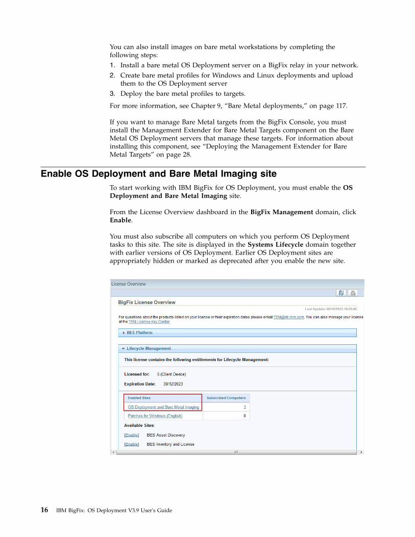
Enable OS Deployment and Bare Metal Imaging siteTo start working with IBM BigFix for OS Deployment, you must enable the OSDeployment and Bare Metal Imaging site.
From the License Overview dashboard in the BigFix Management domain, clickEnable.
You must also subscribe all computers on which you perform OS Deploymenttasks to this site. The site is displayed in the Systems Lifecycle domain togetherwith earlier versions of OS Deployment. Earlier OS Deployment sites areappropriately hidden or marked as deprecated after you enable the new site.
16 IBM BigFix: OS Deployment V3.9 User's Guide

Navigation tree overview
The OS Deployment and Bare Metal Imaging navigation tree, which is accessedfrom the IBM Endpoint Manager console, is your primary tool for capturing anddeploying OS images. This navigation tree becomes available when you enable thesite from the License Overview dashboard in the BigFix Management domain. Toaccess the navigation tree, open the IBM BigFix console and click the SystemsLifecycle domain at the bottom of the domain panel.
Click OS Deployment and Bare Metal Imaging to expand the content, which isorganized into nodes, dashboards, Fixlets, and tasks that you use to prepare andperform OS deployments in your environment:
Health ChecksThe OS Deployment Health Checks Dashboard provides troubleshootingand optimization checks for OS Deployment. You can drill down intoindividual health checks to see their results and a resolution path forfailing checks. See “Health Checks Dashboard” on page 33.
Setup From this node you perform the installation and configuration stepsneeded to successfully prepare and upload MDT bundles, to uploadimages to the Endpoint Management server, and to deploy these images oncomputers in your environment. The Setup node expands to display thedashboards, Fixlets, tasks, and analyses available for this purpose. Eachconfiguration task is described in detail in Chapter 2, “Configuring the OSDeployment Environment,” on page 19and Chapter 3, “Managing MDTBundles and Deployment Media for Windows targets,” on page 37.
Manage Images and DriversThe Manage Images and Drivers node includes wizards and dashboardsfor managing your driver and image libraries, as well as for capturingimages. For more information about images and drivers, see Chapter 6,“Managing Images,” on page 75.
Chapter 1. Product overview 17

.
Manage Bare Metal ServersExpanding this node, you access the Server Management dashboard. Fromthis dashboard you can manage bare metal OS Deployment servers. Youcan install, uninstall, or upgrade Tivoli Provisioning Manager for OSDeployment Servers by uploading the appropriate installers.
After you install, you can create bare metal profiles containing images thatare stored on the server and made available to target computers that PXEboot to that server. When a target selects a profile from the binding menu,the image, the MDT bundle, and all necessary drivers are downloadedthrough the endpoint management infrastructure and the imaging processbegins.
For information about installing a bare metal server and creating profileson your IBM BigFix relay, see “Managing Bare Metal OS DeploymentServers” on page 22.
Manage Scripting EnvironmentsExpanding this node, you access the Scripting Environment Library. Fromthis dashboard you can import scripting environments that you havepreviously created with vendor-specific tools, and deploy them to yourBare Metal targets. The Bare Metal Server that manages the targets musthave the Management Extender for Bare Metal targets component installed.
Maintenance and Configuration TasksThis menu contains Fixlets and tasks that are needed for maintenance ofyour OS Deployment environment. See Chapter 12, “Maintenance andtroubleshooting,” on page 169.
Deploy OS using RAD ProfilesThis menu lists a set of Fixlets you can run to perform bare metaldeployments using imported RAD profiles. For further information, seeAppendix B, “Bare Metal OS Provisioning using RAD Profiles,” on page183.
Bare Metal Target OperationsThis menu contains tasks and Fixlets to manage Bare Metal targets in yourenvironment. See “Managing Bare Metal Targets” on page 150.
18 IBM BigFix: OS Deployment V3.9 User's Guide

Chapter 2. Configuring the OS Deployment Environment
To start working with OS Deployment, run the configuration Fixlets and taskslisted in the Setup Node.
In the Setup node in the navigation tree, you can access reports, dashboards, andwizards that you use to manage repositories and images and set parameters fortheir future use within your deployment.
Perform each task in the Setup Node. Each task is described in detail.
© Copyright IBM Corp. 2010, 2016 19

Install BES Server Plugin Service
The BES Server Plugin Service task enables the Upload Maintenance Service. Fromthe navigation tree, click the task and, when the Fixlet window opens, click in theActions box to deploy the plug-in.
Install or Upgrade Upload Maintenance Service
The Upload Maintenance Service manages files uploaded to the server. This serviceperforms periodic scans to update the OS Deployment and Bare Metal Imagingdata in the database. If you are installing Upload Maintenance Service. for the firsttime, select corresponding entry in the navigation tree and click the link in theActions box.
If your currently installed version of the Upload Maintenance Service is earlierthan 1.0.0.17, select the Upgrade Upload Maintenance Service node in thenavigation tree to use the latest content enhancements and fixes.
20 IBM BigFix: OS Deployment V3.9 User's Guide

To upgrade the Upload Maintenance Service, click the link in the Actions box.
Update Server Whitelist for OS DeploymentThe Update Server Whitelist for OS Deployment Fixlet enables agents todynamically download the necessary driver files.
Click the link in the Actions box to update the server whitelist.
Managing the Linux Image providerThe Linux Image provider component is needed for reimaging Linux systems inyour environment
To deploy images on Linux targets in your network, you must install the Linuximage provider component on the relays to which your Linux targets areconnected. You cannot install the Image Provider component on relays that areBare Metal OS Deployment servers, because this component is already embedded.If your targets are connected directly to an IBM BigFix server, you must install thiscomponent on the server.
Before you deploy Linux systems, you must update the IBM Endpoint ManagerServer whitelist to enable the Linux Image Provider to dynamically download thenecessary files.
Installing the Linux Image Provider
From the OS Deployment and Bare Metal Imaging site, click Maintenance andConfiguration. Select the corresponding task. When you deploy the action, the list
Chapter 2. Configuring the OS Deployment Environment 21

of applicable relays is displayed in the Take Action menu. Select one or morerelays from the list and click OK to begin installation.
This component is installed in C:\Program Files\OSdImageProvider. When theinstallation ends, the component is started automatically. The log file rbagent.logand trace file rbagent.trc are stored in the installation directory
Useful commands
You can start the Linux Image provider by running the "Start Linux ImageProvider" Fixlet, which you can also include in your Server Automation Plans.
You can also run the following batch files to start or stop the Image Provider:v To start the Image provider process:
StartImageProvider.bat
v To stop the Image provider process:StopImageProvider.bat
To increase the log level for problem determination purposes, you can edit theStartImageProvider.bat file. For example:osdimageprovider.exe -d -v 4 -o rad -startimageprovider
raises the log level to 4 from the default level of 3.
Uninstalling the Linux Image Provider
To remove the Linux Image Provider from a relay in your environment, run the"Uninstall Linux Image Provider " task on the relevant relays.
Managing Bare Metal OS Deployment Servers
The Bare Metal Server Manager dashboard manages the installation, upgrade, anduninstallation of Tivoli Provisioning Manager for OS Deployment servers. .
In the dashboard, a list of all Tivoli Provisioning Manager for OS Deploymentservers that are subscribed to the site is displayed. You can install the latest OSDeployment server directly from the network in a single step, or you can uploadthe latest installers for each supported architecture from Fix Central at this url:http://www-933.ibm.com/support/fixcentral/, by providing the necessarycredentials.
22 IBM BigFix: OS Deployment V3.9 User's Guide
||||||

The latest version of the OS Deployment server installer available from thenetwork is displayed at the top left corner of the page. Run the installation byclicking Install and select one or more available relays. Ensure that the relays youselect are subscribed to the OS Deployment and Bare Metal Imaging site. Networkinstallers are available for BigFix 9.0 or later.
If you want to install or upgrade your OS Deployment Servers from the networkbut you already have an installer of an earlier release that you uploaded from FixCentral, you must first delete the existing installer because uploaded installershave precedence over network installations.
If you are upgrading from a previous release, select one or more Bare Metal OSDeployment servers, and click Upgrade.
Note: If the relays you select already have the Image Provider componentinstalled, you must remove it by using the "Uninstall Linux Image Provider Task"before you install the Bare Metal Server.
If you are using BigFix version 9.0 or later, the available computers do not requireSSL Encryption.
If you are using BigFix version 8.2, the available computers to install on are thoserelays that have SSL Encryption enabled.
Accept the license and specify where to install the OS Deployment Server. Beforeyou install, you must enter the user name and password for the login on the OSDeployment Server.
For more information about Tivoli Provisioning Manager for OS Deploymentproduct, see the documentation at the following url:http://www-01.ibm.com/support/knowledgecenter/SS3HLM/welcome.
The Bare Metal Server installation task downloads and installs Microsoft SQLServer Express on the selected relay.
On 64-bit architectures, you can install a Bare Metal Server on a relay that alreadyhas an installed database, and use the existing installation. The following databasesare supported:v DB2 Enterprise 9.1 FP4a, 9.5 FP3b, 9.7, and 10.1v Microsoft SQL Server 2005 SP2 and 2008 R2:
Before you install the Bare Metal OS Deployment server, complete the followingsteps on the existing database installation:1. Create a database with a name of your choice2. Create a Data Source named AutoDeploy using 64-bit ODBC drivers for your
database.
Proceed with the installation of the Bare Metal Server.
Important:
v After you install Tivoli Provisioning Manager for OS Deployment servers fromthe Bare Metal Server manager dashboard, you must create and manage profilesand bare metal deployments from the IBM BigFix Console only, using the BigFixinfrastructure. You cannot manage the server or any deployment objects on itfrom Tivoli Provisioning Manager for OS Deployment interfaces.
Chapter 2. Configuring the OS Deployment Environment 23
|||||
||||

v If you are installing the Bare Metal Server from a BigFix Console running onWindows 2012 R2, the version of Adobe embedded in this operating system maycause bare metal server synchronization problems. To avoid this issue, beforeyou install the Bare Metal Server, ensure that you have installed all the latestMicrosoft patch updates.
v Some functions of the dashboard might be limited if the Bare Metal servers arenot at a minimum required version. When you change a resource on a BareMetal server, such as importing a new MDT Bundle, importing or modifyingdrivers, an action is automatically generated to update the servers.
If any of the resources are out of date, a warning is displayed. Click
tosynchronize the server resources.
The Bare Metal Profiles section of the dashboard lists the available profiles on theBare Metal Server. The cached column displays whether the image associated tothe selected profile is cached on the relay. A green check mark indicates that thecorresponding image is currently cached at the relay. A yellow warning iconindicates that the corresponding image is not cached at the relay and will becopied when the profile is deployed for the first time. A red border triangleindicates that the caching status of the image cannot be determined.
To view the status of the services on an installed OS Deployment Server, select the
server from the list and click
to view or modify the current settings:
24 IBM BigFix: OS Deployment V3.9 User's Guide

You can start, stop or restart the Bare Metal Server, and view if any errors werelogged.
When you deploy a Bare Metal Profile for the first time, the images linked to theprofile are cached (copied) on the relay. If network traffic is slow, the cachingmight take a long time and cause the deployment of the Bare Metal Profile to fail.The default timeout value is written in the bom.trcfile. You can change this valuein the Relay Downloader Timeout field. Specify the maximum time (in seconds)allowed to download an image from the Endpoint Management server to the relayif the image is not cached. Click Sync to update this value on the Bare MetalServer.
Cleaning up after a failed installation or uninstallation
If the installation or uninstallation of the OS Deployment Server on your relayfails, you can run the Bare Metal Server Clean Up Post-Uninstall or Install failuretask (ID 134) from the Systems Lifecycle domain. Use this task only when youwant to avoid system inconsistencies that might occur after a failure or when theinstallation or uninstallation task processing is incomplete.
Note:
This task removes SQL Express database from the target system. Do not run thistask if there are other applications using this database. Do not run this task on OSDeployment Servers that are listed as installed in the Bare Metal OS DeploymentServer Manager dashboard. On these servers, you must first run an uninstallaction.
Ports used by the Bare Metal OS Deployment ServerTo ensure correct communication, check the ports used for the differentdeployment scenarios.
Listening ports used during client network boot (PXE/TFTPprotocols):
By default, Bare Metal OS Deployment Servers and targets use the following portsfor communication:
Bare Metal Server:v DHCP : port 67 UDP
v PXE BINL : port 4011 UDP
v TFTP : port 69 UDP
Bare Metal Target:v DHCP : port 68 UDP
v PXE BINL : port 4011 UDP
Note: PXE and TFTP ports are not needed when using network boot media.
Chapter 2. Configuring the OS Deployment Environment 25

Listening ports used for OS Deployment tasks, media creationand reimaging deployments in multicast
To reimage target computers (BES clients) using multicast communication, the BareMetal Server must be installed and running on the relay(s) to which the targets areconnected.
Bare Metal Server:v NBP : port 4012 UDP
v FILE: port 4013 UDP & TCP
v MCAST: ports 10000-10500 UDP
v HTTP: port 8080 TCP
v HTTP: port 8088 TCP - Image Provider component used during Linuxdeployments
v Database gateway: port 2020 TCP
v HTTP: port 52311 TCP - Relay Downloader
Bare Metal and Reimaging Targets:v NBP : port 4014 UDP
v MCAST : port 450 UDP
v MCAST : port 451 UDP
v MCAST : port 9999 UDP
Ports for direct Web UI access (optional)
Bare Metal Server:v HTTP: port 8080 TCP
v HTTPS : port 443 TCP
Configuring the DHCP serverTo connect targets to the OS Deployment server, you might need to configure theDHCP server based on the characteristics of your network.
The DHCP server is used by the PXE bootrom to get its IP address and other basicnetworking information (including subnet mask, and default gateway). UsingBigFix OS Deployment can require changes to your DHCP configuration. Thesechanges can typically be performed automatically by the Tivoli ProvisioningManager for OS Deployment installer. However, in some cases, you might want toperform the changes manually, or to verify them.
Important: If your DHCP Server is configured to use option 210pxelinux.pathprefix(), this option causes the PXE boot to fail on bare metaltargets. This option must not be configured for bare metal deployments.
You can configure your DHCP server for one of the three following situations:v The DHCP server and the OS deployment server are not running on the same
hostv The DHCP server and the OS deployment server are running on the same hostv You already have a PXE 2.0 infrastructure with PXE Boot Server discovery
installed and you want to add BigFix OS Deployment to the list of servers todiscover.
26 IBM BigFix: OS Deployment V3.9 User's Guide

Note:
v f you have previously configured your DHCP server for another PXE bootstrap,do not reuse your existing DHCP configuration. Remove DHCP options 43 & 60for the hosts on which you want to run BigFix OS Deployment and follow theinstructions given in this section (if you are running BigFix OS Deployment onthe same host as the DHCP server, you need to set option 60 again).
v There are also cases where you must set both DHCP options 43 & 60, includingwhen you have two different OS Deployment Servers in your environment.
DHCP server and OS deployment server on different targets,without information on PXE server location
Actions to perform:v If DHCP options 43 and 60 are set, remove them.v If the DHCP server is not running on the same computer as the OS deployment
server, the DHCP configuration does not change. The OS deployment serverdetects DHCP packets sent over the network by PXE bootroms and offers PXEparameters without disturbing standard DHCP negotiation process. Thisbehavior is called DHCPProxy.
Note: This configuration is not allowed if more than one OS deployment serveris defined in the same environment. In the OS deployment server WebUI ensurethat the DHCP proxy functionality is disabled: Server parameters > Serverconfiguration > Disable the DHCP proxy functionality = NO (default value).
DHCP server and OS deployment server on different targets, withinformation on PXE server location
Actions to perform:v Set option 60 (Class identifier) to "PXEClient" to inform the target that the
location of the PXE server is known.v Set option 43 to indicate that the PXE server does not reside on the same
computer as the DHCP server and to precise the location of the PXE server.
Note: This configuration is mandatory if more than one OS deployment serveris defined in the same environment.
Note: Some UEFI targets are not able to correctly process option 43. For thosetargets it is necessary to set option 66 and 67.
For detailed information about setting options, 43, 60, 66 and 67, see TivoliProvisioning Manager for OS Deployment Installation Guide, Chapter 4: DHCPserver configuration.
DHCP server and OS deployment server on the same target
Set your DHCP server to send DHCP option 60 (Class identifier) to the target.When option 60 is set to PXEClient the DHCP server knows where the PXE serveris. If option 43 is not set, the PXE server has the same IP address as the DHCPserver.
For detailed information about setting option 60, see Tivoli Provisioning Managerfor OS Deployment Installation Guide, Chapter 4: DHCP server configuration.
Chapter 2. Configuring the OS Deployment Environment 27
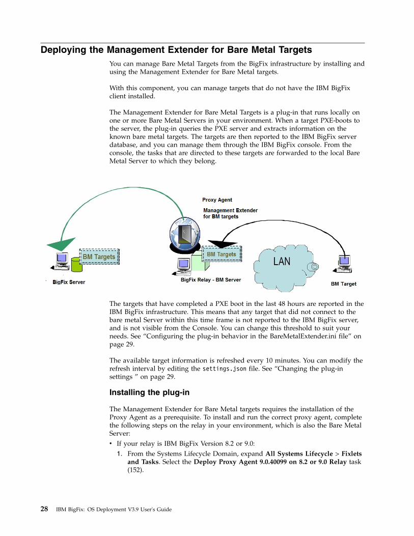
Deploying the Management Extender for Bare Metal TargetsYou can manage Bare Metal Targets from the BigFix infrastructure by installing andusing the Management Extender for Bare Metal targets.
With this component, you can manage targets that do not have the IBM BigFixclient installed.
The Management Extender for Bare Metal Targets is a plug-in that runs locally onone or more Bare Metal Servers in your environment. When a target PXE-boots tothe server, the plug-in queries the PXE server and extracts information on theknown bare metal targets. The targets are then reported to the IBM BigFix serverdatabase, and you can manage them through the IBM BigFix console. From theconsole, the tasks that are directed to these targets are forwarded to the local BareMetal Server to which they belong.
The targets that have completed a PXE boot in the last 48 hours are reported in theIBM BigFix infrastructure. This means that any target that did not connect to thebare metal Server within this time frame is not reported to the IBM BigFix server,and is not visible from the Console. You can change this threshold to suit yourneeds. See “Configuring the plug-in behavior in the BareMetalExtender.ini file” onpage 29.
The available target information is refreshed every 10 minutes. You can modify therefresh interval by editing the settings.json file. See “Changing the plug-insettings ” on page 29.
Installing the plug-in
The Management Extender for Bare Metal targets requires the installation of theProxy Agent as a prerequisite. To install and run the correct proxy agent, completethe following steps on the relay in your environment, which is also the Bare MetalServer:v If your relay is IBM BigFix Version 8.2 or 9.0:
1. From the Systems Lifecycle Domain, expand All Systems Lifecycle > Fixletsand Tasks. Select the Deploy Proxy Agent 9.0.40099 on 8.2 or 9.0 Relay task(152).
28 IBM BigFix: OS Deployment V3.9 User's Guide

2. When you deploy the action, the list of applicable relays is displayed in theTake Action menu. Select one or more relays from the list and click OK tocomplete the installation.
3. Run the task Deploy Management Extender for Bare Metal Targets (ID 150)v If your relay is at IBM BigFix version 9.1 or later:
1. From the BES Support site, search and run fixlet Install IBM BigFix ProxyAgent (Version 9.1.1117.0) (1816) or Install IBM BigFix Proxy Agent(Version 9.2.0) (1836), depending on your platform version.
2. When you deploy the action, the list of applicable relays is displayed in theTake Action menu. Select one or more relays from the list and click OK tocomplete the installation.
3. Run the task Deploy Management Extender for Bare Metal Targets (ID 150)
The plug-in is installed in the path C:\Program Files(x86)\BigFixEnterprise\Management Extender. The service is started automatically.
After the Bare Metal targets PXE-boot, you can view and manage them from theconsole. A set of tasks are available to manage these targets. For more information,see “Managing Bare Metal Targets” on page 150.
Configuring the plug-in behavior in the BareMetalExtender.ini file
You can change the behavior of the plug-in by configuring parameters in theBareMetalExtender.ini file .
The LastReportTimeThreshold parameter defines the time window that is takeninto account to determine if the bare metal target that completed a PXE boot is stillactive. The default is set to 48 hours. You can configure this threshold to suit yourspecific needs and environment.
To change the reporting threshold for the bare metal targets, switch to C:\ProgramFiles\Common files\IBM Tivoli. Edit the BareMetalExtender.ini, and modify thevalue of the corresponding parameter:LastReportTimeThreshold=48
Changing the plug-in settings
You can also customize parameters in the settings.json file.
You can decide the logging detail by modifying the configuration options. Toincrease the logging level for troubleshooting purposes, edit the C:\Program Files(x86)\Bigfix Enterprise\Management Extender\Plugins\Bare MetalExtender\settings.json file. For example, to change the logging level from 3 to 4:"ConfigurationOptions" -d v 4
To change the circular logging default values, edit the -m X:Y setting, where X isthe maximum file size in Megabytes, and Y is the maximum number of log/tracefiles. The default value is -m 10:10. For example, to change the maximum numberof trace files from a value of 10 to a value of 5:"ConfigurationOptions": "-d -v 3 -l \\\"C:\\Program Files\\Common Files
\\IBM Tivoli\\BareMetalExtender.log\\\" -t \\\"C:\\Program Files\\Common Files\\IBM Tivoli\\BareMetalExtender.trc\\\" -m 10:5",
Chapter 2. Configuring the OS Deployment Environment 29

The target information is retrieved and refreshed on the server every 10 minutes. Ifyou want to modify the default refresh interval for retrieving this information from10 to 15 minutes, overwrite the default value, as shown in the following example:"DeviceReportRefreshIntervalMinutes": 15,
The DeviceReportExpirationIntervalHours parameter defines the expiration periodafter which a bare metal target is considered inactive and can be erased. After thisperiod has expired, the plug-in will stop tracking information for the target. Thedefault value for this interval is 168 hours. You can modify the expiration periodby locating the corresponding string:"DeviceReportExpirationIntervalHours": 168,
After this interval has elapsed, the entry for the target in the SubscribedComputers can be erased. For information about deleting bare metal target entries,see “Deleting bare metal target entries ” on page 152.
After you make changes to the settings in this file, the Proxy Agent service mustbe restarted for the modifications to take effect.
Starting the service
You can start the Proxy Agent service by running the Start Proxy Agent Fixlet (75).
Uninstalling the plug-in
To remove the Management Extender for Bare Metal Targets, complete thefollowing steps:1. Run the Remove Management Extender for Bare Metal Targets fixlet (ID 151).2. Remove the Proxy Agent:v If your relay is at IBM BigFix Platform Version 8.2 or 9.0:
– Run the remove action of the Deploy Proxy Agent 9.0.40099 on 8.2 or 9.0Relay fixlet (ID 152)
v If your relay is at IBM BigFix Platform Version 9.1 or later:– From the BES Support site, run the task TROUBLESHOOTING: Uninstall
IBM BigFix Proxy Agent (ID 1795)
Troubleshooting
Logs for troubleshooting are on each Bare Metal Server in %CommonProgramFiles%\IBM Tivoli\BareMetalExtender.trc. The default logging level is 3. You can changecircular logging options in the settings.json file. See “Changing the plug-insettings ” on page 29.
Activating AnalysesTo start using OS Deployment, activate the analyses shown in the Setup node inthe navigation tree. Click each analysis from the navigation tree, and then click thelink provided in the analysis window to activate it.
SSL Encryption Analysis for OS DeploymentThe SSL Encryption Analysis for OS Deployment is used to return the public keyson clients ready for OS deployment. These keys can be used to securely deploysettings to the endpoint.
30 IBM BigFix: OS Deployment V3.9 User's Guide

The SSL Encryption Analysis is needed only for encrypting actions to BigFix clientsversion 8.2, not for version 9.0 clients or later. If all clients are at version 9.0 orlater, this is unnecessary.
Click the link in the Actions box to activate this analysis.
OS Deployment Server InformationThe OS Deployment Server Information is used to gather the versions of OSdeployment servers that have been deployed.
Click the link in the Actions box to activate this analysis. To install an OSDeployment server, see “Managing Bare Metal OS Deployment Servers” on page22.
Re-image Failure InformationThe Re-image Failure Information is used to retrieve information from machinesthat failed to boot into the Windows preboot environment and were unable tosuccessfully re-image. This information is used in the Activity Dashboard tochange the driver bindings and try the boot again.
Chapter 2. Configuring the OS Deployment Environment 31

Click the link in the Actions box to activate this analysis.
Hardware InformationThe Hardware Information analysis is used to filter drivers by compatiblehardware models and to calculate which drivers are used during a deployment.
Click the link in the Actions box to activate this analysis.
Bundle Creator Machine InformationThe Bundle Creator Machine Information analysis returns information abouttargets with the Bundle Creator installed and the version of the installation.
Click the link in the Actions box to activate this analysis.
32 IBM BigFix: OS Deployment V3.9 User's Guide

Bare Metal Target informationThis analysis contains information about the Bare Metal Targets managed by BareMetal OS Deployment Servers with the Management Extender for Bare MetalTargets component installed.
Click the link in the Actions box to activate this analysis.
Health Checks Dashboard
The OS Deployment Health Checks Dashboard provides troubleshooting andoptimization checks for OS Deployment. For both the General and Bare Metalpanels, you can drill down into individual health checks to see the results and aresolution path for failing checks.
Use the Health Checks - General dashboard to see the current health status of theIBM BigFix infrastructure.
Chapter 2. Configuring the OS Deployment Environment 33

Use the Health Checks - Bare Metal dashboard to see the current health status ofthe IBM BigFix infrastructure if you want to install additional components for baremetal deployment.
34 IBM BigFix: OS Deployment V3.9 User's Guide

If the deployment was set up correctly, all the results are shown as Pass. If theresult of any check is Fail, expand the node and take the recommended action.
Enable Encryption for ClientsThe Enable Encryption for clients Fixlet deploys the Crypto Utility to the BESClient folder and generates a set of public and private keys. This Fixlet is aprerequisite for the installation of Tivoli Provisioning Manager for OS DeploymentServer to manage bare metal deployments in V8.2 environments. It is mandatoryonly if the relay on which you are installing your Bare Metal Server is BigFixversion 8.2 or you have V8.2 clients in your environment. Run this Fixlet on yourdesignated relay before installing the Bare Metal Server.
Click the link in the Actions box to enable encryption for clients.
Verifying Secure Hash Algorithm (SHA-256) readinessIBM BigFix version 9.1 uses the SHA-256 hashing algorithm to increase fileexchange security. OS Deployment manages file exchange within the applicationflows using SHA-256.
From IBM BigFix Version 9.1, all application-specific files are managed withSHA-256. All new files uploaded by the user (images, drivers, MDT bundles etc.)and generated by the system after the installation of IBM BigFix version 9.1 arecreated with the SHA-256 hashing information included, and are managedaccordingly. The files that were uploaded and created on earlier BigFix versions, donot have the SHA-256 information. You can continue to use these files, but fileexchange will not benefit from the improved security provided by SHA-256.
If the IBM BigFix Server is configured to allow exchange of files in SHA-256 modeonly, then it will no longer be possible to use files created with earlier versions ofBigFix .
To verify SHA-256 readiness, the health check named "OS deploymentEnvironment is SHA-256 compliant" scans for files that do not have SHA-256information. The outcome of this check can result in a warning message indicatingthat some files are not SHA-256 compliant. You can start an action to calculate themissing SHA-256 information and to automatically update the affected files fromthe Resolution section of the health check. If the action does not update one ormore files, you can display the file names for further problem determination. Whenthe action completes successfully, the status changes to "Pass". In this case, asynchronization action is automatically started to update the hashing informationon Bare Metal servers in the network.
Chapter 2. Configuring the OS Deployment Environment 35

If the IBM Endpoint Management Server is configured to allow the exchange offiles in SHA-256 mode only, a warning banner is also displayed in the OSDeployment dashboards, with an indication for the user if the SHA256 compliancehealth check status is not "Pass". Clicking on the banner opens the Health Checksdashboard from where you can start a remediation action.
36 IBM BigFix: OS Deployment V3.9 User's Guide
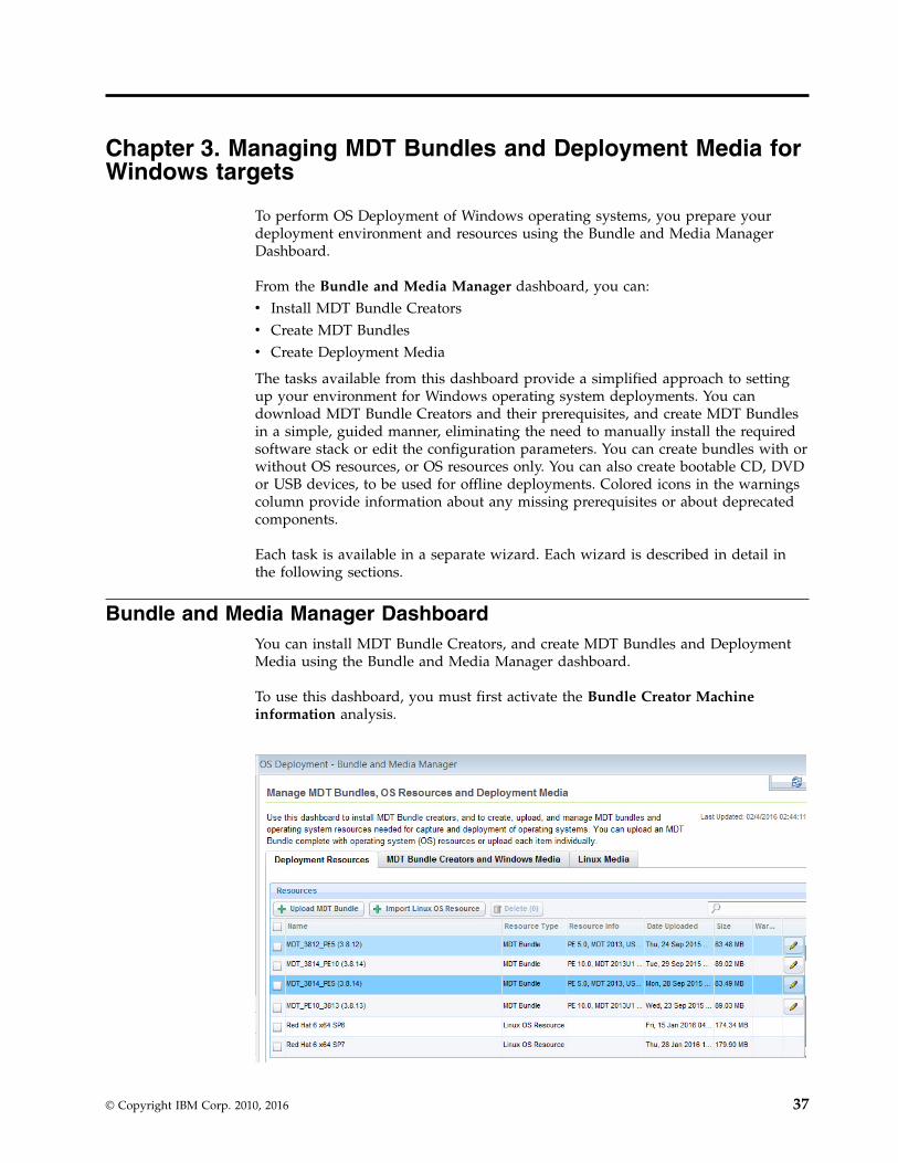
Chapter 3. Managing MDT Bundles and Deployment Media forWindows targets
To perform OS Deployment of Windows operating systems, you prepare yourdeployment environment and resources using the Bundle and Media ManagerDashboard.
From the Bundle and Media Manager dashboard, you can:v Install MDT Bundle Creatorsv Create MDT Bundlesv Create Deployment Media
The tasks available from this dashboard provide a simplified approach to settingup your environment for Windows operating system deployments. You candownload MDT Bundle Creators and their prerequisites, and create MDT Bundlesin a simple, guided manner, eliminating the need to manually install the requiredsoftware stack or edit the configuration parameters. You can create bundles with orwithout OS resources, or OS resources only. You can also create bootable CD, DVDor USB devices, to be used for offline deployments. Colored icons in the warningscolumn provide information about any missing prerequisites or about deprecatedcomponents.
Each task is available in a separate wizard. Each wizard is described in detail inthe following sections.
Bundle and Media Manager DashboardYou can install MDT Bundle Creators, and create MDT Bundles and DeploymentMedia using the Bundle and Media Manager dashboard.
To use this dashboard, you must first activate the Bundle Creator Machineinformation analysis.
© Copyright IBM Corp. 2010, 2016 37
From this dashboard you can:v Install MDT Bundle Creators from the MDT Bundle Creators and Windows
Media tab, by clicking Install MDT Bundle Creator . In the wizard, select thetool combination that best suits your deployment patterns. When you select thetools, the corresponding set of supported operating systems is highlighted.
v Create MDT Bundles for the operating systems you plan to deploy. An MDTBundle is a collection of scripts, OS resource files, and folders that are requiredfor reimage, capture, and bare metal deployments. When you create an MDTbundle, these resources must be specified for each operating system,architecture, and Service Pack combination that you plan to deploy in yourenvironment.The Create MDT Bundle wizard detects the software stack available on theselected Bundle Creator machine. Based on the installed software, it guides youin selecting the correct resources for the creation of the MDT Bundle. The targeton which the bundle is created must have either Windows AutomatedInstallation Kit (WAIK) or Windows Assessment and Deployment Kit (WADK).
v Create network boot and offline deployment media from the CreateDeployment Media wizard, to boot systems when a PXE server is not available,and to deploy profiles to targets that are disconnected from the network. Thesupported media types are USB, CD, and DVD devices.
For each target , the table displays information about the following:v the version of the OS Deployment server that is installedv which MDT Bundle Creator version is installedv which Deployment kit is installed
The Warnings column indicates whether some prerequisites are missing, or ifcomponents are not at the required version or level for the available tasks.
You can install the MDT Bundle Creator on a computer manually, by using theMDT Bundle Creator Setup node. If the creators you installed manually are onsystems with the Endpoint Manager client installed, they are displayed in the listof available MDT Bundle creators. You can also create MDT Bundles manually bycustomizing the required parameters in the parameters.ini file, and by launchingthe MDT Bundle Creator executable. For information about manual installation andconfiguration, see “Creating and managing MDT bundles manually” on page 48.
Note: If you have installed MDT Bundle Creators with versions earlier than 3.4,these computers are visible in the dashboard, but the Create MDT Bundle wizardis disabled for these targets.
Installing MDT Bundle CreatorsFrom the Bundle and Media Manager dashboard, you can install MDT BundleCreators on selected targets.
In the Bundle and Media Manager dashboard , select the MDT Bundle Creatorsand Windows Media tab and click Install MDT Bundle Creator to start thewizard.
38 IBM BigFix: OS Deployment V3.9 User's Guide

Choose the combination of tools that best matches your deployment needs. Foreach choice, the list of operating systems that can be deployed is automaticallydisplayed Click Next.
Depending on the target you select for the installation, additional prerequisitesoftware can be automatically downloaded and installed. You are asked to agree tothe license statements regarding this software. Click Submit to take action, andselect one or more targets where the Bundle Creator will be downloaded.
Important:
v The computers on which you install the MDT Bundle creators must have directinternet access for the prerequisites to be correctly downloaded and installedthrough the wizard.
v If you select to download and install the MDT Bundle Creator with WADK 10and MDT 2013 Update 1 on a Windows 2008, Windows 2008 R2, or Windows 7target, Microsoft .NET Framework Version 4.5 must already be installed on thetarget before you install the MDT Bundle Creator.
v You don't need to create an MDT bundle for Windows 10 in-place upgrades. Formore information, see Chapter 8, “Installing Windows 10 using in-placeupgrade,” on page 115.
MDT Bundle Creators and valid component combinations
The following table lists the valid combinations for components using the MDTBundle Creator Tool 3.8 and 3.9. For each combination, there is a corresponding listof operating systems that you can deploy.
Chapter 3. Managing MDT Bundles and Deployment Media for Windows targets 39

Table 1. Valid component combinations for MDT Bundle Creator
MDT BundleCreator
MicrosoftDeploymentToolkit WIM Toolkit Operating Systems
MDT Bundle Creator3.8 and 3.9 1,2
2013 Update 1 WADK 10 (WinPE 10) v Windows 10
v Windows 8.1
v Windows 8
v Windows 7
v Windows Server2012 R2 3
v Windows Server2012
v Windows Server2008 R2
See Note 2.
2013 WADK 8.1 (WinPE 5) v Windows 8.1
v Windows 8
v Windows 7
v Windows Server2012 R2 3
v Windows Server2012
v Windows Server2008 R2
2012 Update 1 WADK 8 (WinPE 4) v Windows 8
v Windows 7
v Windows Vista
v Windows XP
v Windows Server2012
v Windows Server2008 R2
v Windows Server2008
v Windows Server2003
2012 Update 1 WAIK (WinPE 3) v Windows 7
v Windows Vista
v Windows XP
Notes:
1. MDT Bundle Creator 3.9 supersedes all previous versions2. To deploy Windows 10 and other supported Windows versions using WADK
10 (WinPE 10) and MDT 2013 Update 1, you must use MDT Bundle CreatorVersion 3.8.12 or later.
3. Windows 2012 R2 is supported only with MDT Bundle Creator 3.4 or later.
40 IBM BigFix: OS Deployment V3.9 User's Guide

Target operating systems for reimaging and bare metalprovisioning
The following table lists, for each supported operating system, the componentcombinations you can use for reimaging and bare metal deployments.
Table 2. Target operating systems and component combinations for reimaging and baremetal provisioning
Operating SystemMDT BundleCreator 1
MicrosoftDeployment Toolkit WIM Toolkit
Windows 10 3.8, 3.9 2013 Update 1 WADK 10 (WinPE 10)
Windows 8.12 3.8, 3.92013 Update 1 WADK 10 (WinPE 10)
2013 WADK 8.1 (WinPE 5)
Windows 8 3.8, 3.9
2013 Update 1 WADK 10 (WinPE 10)
2013 WADK 8.1 (WinPE 5)
2012 Update 1 WADK 8 (WinPE 4)
Windows 7 3 3.8, 3.9
2013 Update 1 WADK 10 (WinPE 10)
2013 WADK 8.1 (WinPE 5)
2012 Update 1 WADK 8 (WinPE 4)
2012 Update 1 WAIK (WinPE 3)
Windows Vista 3.82012 Update 1 WADK 8 (WinPE 4)
2012 Update 1 WAIK (WinPE 3)
Windows XP 3.82012 Update 1 WADK 8 (WinPE 4)
2012 Update 1 WAIK (WinPE 3)
Windows Server 2012R2
3.8, 3.92013 Update 1 WADK 10 (WinPE 10)
2013 WADK 8.1 (WinPE 5)
Windows Server 2012 3.8, 3.9
2013 Update 1 WADK 10 (WinPE 10)
2013 WADK 8.1 (WinPE 5)
2012 WADK 8 (WinPE 4)
Windows Server 2008R2
3.8, 3.9
2013 Update 1 WADK 10 (WinPE 10)
2013 WADK 8.1 (WinPE 5)
2012 Update 1 WADK 8 (WinPE 4)
Windows Server 2008 3.8 2012 Update 1 WADK 8 (WinPE 4)
Windows Server 2003 3.8 2012 Update 1 WADK 8 (WinPE 4)
Notes
1. MDT Bundle Creator 3.8 supersedes all earlier versions. To deploy Windows 10and other supported Windows versions (reimaging and bare metaldeployments) with WADK 10 (WinPE 10) and MDT 2013 Update 1, you mustuse MDT Bundle Creator 3.8.12 or later, and the Bare Metal OS DeploymentServer must be Version 7.1.1.19 or later. When reimaging to Windows 10, thesource operating system must have IBM BigFix client version 9.2.5 or laterinstalled before you start the reimage process.
2. Direct reimaging from Windows XP or Windows Vista to Windows 8.1 is notsupported. It must done as a two-step process. You must first reimage thetarget to Windows 7 or Windows 8, and subsequently reimage to Windows 8.1.
Chapter 3. Managing MDT Bundles and Deployment Media for Windows targets 41

3. When reimaging from Windows XP to Windows 7, WinPE 5 and WinPE 10 arenot supported.
For a complete list of WinPE versions and Operating System support, see theinformation provided at this url: http://technet.microsoft.com/en-us/library/dn293271.aspx
Creating and uploading MDT BundlesUsing this wizard, you create MDT Bundles and OS resources for your Windowsdeployments.
From the MDT Bundle Creators Tab, select a target and click Create MDT Bundle.This option is disabled if the target you selected does not have WindowsAutomated Installation Kit (WAIK) or Windows Assessment and Deployment Kit(WADK) installed.
From the wizard, you can choose one of the following tasks:v Create both MDT bundle and OS resourcesv Create a new MDT bundle onlyv Create new OS resources only
Depending on the tool combinations installed on your target, the wizard displaysthe set of parameters that you can choose from.
If you are creating OS resources, you can choose to include ISO images from aspecific directory on the target, or include specific ISO image files by specifying thefile names, or both. The folder you specify can be either local to the target, or amapped drive on the target system. In the latter case, you must specify the IPaddress and the credentials needed to mount the drive.
You can also create OS resources from the Image Library when you import the ISOimages directly from installation media.
If you plan to reimage to Windows XP, select the corresponding option. USMT3 isrequired for reimaging to XP, and you are asked to specify the path of the USMT3installation.
Note: The Manual tab displays the parameters.ini file, where all specified optionsare stored. Editing this section incorrectly could result in failures during theupload of the MDT bundle.
When you have created your MDT Bundles, you can upload them to the BigFixServer from the MDT Resources tab. To upload an MDT Bundle, click UploadMDT Bundle.
When you upload the MDT bundle, if you expand the Preferences section, you canset the Overwrite Preinstallation Environments option. Select Yes, to overwritePreinstallation Environments previously loaded on the server. The default setting isAuto. With the default setting, the Preinstallation Environments are overwrittenonly if the version you are uploading is the same or later than the currently savedversions.
42 IBM BigFix: OS Deployment V3.9 User's Guide

Creating Windows Deployment MediaYou can generate network boot and offline deployment media for Windows OSdeployments from the Bundle and Media Manager Dashboard.
From the dashboard, click Create Deployment Media to complete one of thefollowing tasks:v Generate an iso file to burn a CD/DVD mediav Create a USB deployment media on a mounted USB key, which can be formatted
before creation.v Generate USB key content for later creation of USB deployment media.
Depending on your selection, the CD, DVD, or USB media can include:v WinPE only (network boot): In this case, when WinPE starts from the media,
the target boots and connects to the Bare Metal OS deployment server (PXEserver) to receive the binding menu.
v WinPE and one or more bootable images (offline deployment): In this case,when the boot operation completes on the target, the binding menu is displayed.The user at the target can select the profile to deploy from the media.
Based on the Windows Deployment Kit installed on the selected target, the correctversion of Windows Preinstallation environment (WinPE) is downloaded from thespecified Bare Metal OS deployment server and included in the media.
Note: The OS Deployment Server from which you download the files that areneeded for creating the media must be at Version 7.1.1.17 or later.
During the media creation process, files are stored in a temporary folder on theselected Bare Metal OS deployment server. By default, the temporary folder iscreated in the system TEMP folder. When the process completes, the folder is erased.To specify a different path for the temporary folder, complete the following stepsbefore you create the media:
Chapter 3. Managing MDT Bundles and Deployment Media for Windows targets 43

1. From the subscribed computers list, locate the Bare Metal OS deploymentserver and edit the computer settings.
2. Add the custom setting BAREMETAL_CURRENT_MEDIATMP and specify the new pathin the value field. This path must already exist on the selected server. If thespecified path is not found, the temporary folder is created in the default path.
3. After the task completes successfully, create the media.
Creating network boot media
The use of network boot media is useful in situations where a DHCP server is notavailable, or when there is a firewall that is preventing PXE traffic.
To create a network boot CD/DVD or USB media complete the following steps:1. On the Media Type pane select the target, then select Create Network Boot
Media, and click Next.2. Select the OS Deployment server from which the files used to create the media
are downloaded, and click Next.3. Depending on the deployment kit that is installed on the selected target, the
Create Deployment Media page displays the version of WinPE that is includedin the media. You can specify, select, or change the following settings:a. The OS architecture .b. Optionally, you can choose to include all available WinPE drivers in the
media. This option is useful only when you have a new computer modelwhich is not listed among the available models in the Driver Library, and abinding grid cannot be generated to associate the correct drivers for thedevices. A preferable alternative is to add the new computer model to yourBigFix environment in one of the following two ways:v Install an operating system on the computer of that model and connect it
to the BigFix infrastructure through a BES client.or
v PXE boot a computer of that model to a Bare Metal server where theManagement Extender for Bare Metal targets is installed and running.
c. You must specify the password of the administrative user on the OSDeployment Server you selected in the previous page. The WindowsPreinstallation Environment is downloaded from this server.
d. The type of media: CD/DVD, mounted USB key, or USB key content. Youcan optionally select to format the USB-mounted media. For the USBcontent, you must specify a target directory. Two scripts are downloaded inthe specified target directory, formatUSB.cmd and MakeUSB.cmd Depending onyour selections, some restrictions might apply. See Network boot medialimitations.
e. Specify the connection details for the target PXE boot. By default, the OSDeployment server that the target contacts when the PXE boot operation iscomplete is automatically discovered. You can specify the connectionparameters either explicitly or at boot time. You must always specify thepassword of the administrative user on the OS Deployment Server.
f. Select the type of network configuration settings that are assigned to theclient at boot time. By default, a dynamic IP address is assigned (DHCP).Alternatively, you can specify a static IP address, network mask, andgateway address. If you specify static network settings, you can overwritethem at boot time by checking the corresponding option.
44 IBM BigFix: OS Deployment V3.9 User's Guide

g. You can optionally specify to have the user start the boot sequence on thetarget. In this case, a prompt is displayed on the target and the bootsequence begins only when the user responds to the prompt.
4. When you have completed your selections, click OK. The information that youprovided is validated before the media creation task begins.
Network boot media limitations: The following restrictions apply to network bootmedia:v If you select the USB Key content media type, you must format the USB key
with a single bootable FAT32 partition of at least 512 Megabytes. To format theUSB key, you can use the formatUSB.cmd script. USB keys that are formatted asNTFS file systems are not supported on UEFI targets.
v If you select mounted USB key and no formatting option, for the key to work onUEFI targets, you should first format the key with a single bootable FAT32partition of at least 512 Megabytes.
Important: When a target connects to a bare metal server using a network bootCD, a binding menu with all available profiles on that server is displayed.However, because the WinPE that is included in the boot media is downloadedand started on the target , only profiles with an MDT bundle with the same WinPEversion can be deployed successfully.
Creating offline deployment media
Offline deployment media can be used when the target has no connection to theOS Deployment Server or when the network connection is slow. Some typicalsituations are small branch offices with slow links and no local deployment server,isolated computers that are disconnected from an internal network, or notebookusers that cannot connect to the local area network or are using a modem. Whenyou create offline deployment media, all necessary files for the deployment aredownloaded.
Note: The installation of Windows XP using offline deployment media is notsupported.
From the Bundle and Media Manager dashboard, click the MDT Bundle Creatorstab, select a target from the list and click Create Deployment Media. The MediaType window is displayed:
To create an offline deployment CD/DVD or USB media complete the followingsteps:1. On the Media Type window, select the target, then select Create Offline
Deployment Media, and click Next.2. In the OS Deployment Server and Bare Metal Profile pane, select theOS
deployment serverfrom which the files used to build the media aredownloaded.
3. The Bare Metal Profiles available at the selected OS deployment server aredisplayed. The profiles that you can choose from are filtered and meet thefollowing requirements:v contain MDT Bundle Version 3.6 or later with the level of WinPE compatible
with the deployment kit installed on the target where you are creating themedia.
v contain OS images that are compatible with the deployment kit installed onthe target where you are creating the media.
Chapter 3. Managing MDT Bundles and Deployment Media for Windows targets 45
|||||

Profiles that do not meet these criteria are not displayed. Select one or moreprofiles to include in the media you are creating. Click Next.
Note: If the profiles you select have a hostname rule containing variables forIP or MAC addresses, their values are substituted with zero (0) at runtime. Forexample, Win10-[IP] becomes Win10-[0000] on the target.
4. In the Create Deployment Media window, some selections are already made,based on your input in the previous window.v You must specify the password of the administrative user on the OS
Deployment server that you selected in the previous window. The passwordis needed only if the target used for creating the media is not an OSDeployment server.
v Select the type of media you want to create. If you select the USB Keycontent, you must specify an output directory. Two scripts are downloadedin the specified directory, formatUSB.cmd and MakeUSB.cmd. Depending on theselected media type, some restrictions might apply. See Offline deploymentmedia limitations
v You can optionally specify to have the user start the boot sequence on thetarget. In this case, a prompt is displayed on the target and the bootsequence begins only when the user responds to the prompt.
5. When you completed your selections, click OK. The information that youprovided is validated before the media creation task begins.
Offline deployment media limitations: The following restrictions apply to offlinedeployment media:v CD/DVD media types are not supported for deployment on UEFI targets.v If your media type is a mounted USB key:
– If you select the Format the USB key option, the USB media must be seen asa fixed disk and not as removable. Typically, Flash Drive USB cards are seenas fixed disks and can be used.
– If you do not choose the formatting option, you must first format the keywith two partitions, of which the first must be a bootable FAT32 partition ofat least 512 Megabytes, and the second partition a non-bootable NTFSpartition, large enough to store the selected images. The USB media must beseen as a fixed disk and not as removable.
v If your media type is USB Key Content:– If you want to use the key for deployments on UEFI targets, you must format
the USB key with two partitions, of which the first must be a bootable FAT32partition of at least 512 Megabytes, and the second partition a non-bootableNTFS partition, large enough to store the selected images. The USB key canalso be formatted with a single partition. In this case, if you want to use it onUEFI targets, the partition must be FAT32 and not NTFS. To format the keyyou can use the formatUSB.cmd script, and you can populate the contents byusing the makeUSB.cmd script.
Note: To complete the operating system deployment successfully on the target,ensure that the hard disk device on your target is configured before the CD/DVDor USB media device in the boot sequence. Then, force the boot from the mediadevice to start the deployment. Alternatively, only for CD/DVD media, select theBoot at User Request option during the creation of the media.
46 IBM BigFix: OS Deployment V3.9 User's Guide

Formatting and loading USB key content
When you are creating network boot or offline deployment USB key content, allfiles that are needed for booting from the network or for offline deployments ofoperating systems on targets are stored in the specified folder on the selectedtarget. In this path, two scripts that are named formatUSB.cmd and makeUSB.cmd aredownloaded. You can run these scripts to format and load the folder content onthe USB key. To run the scripts, open a Windows shell with administrativeprivileges.
Offline deployment media preparation:
formatUSB.cmdUse this script to format your offline deployment USB key with abootable FAT32 partition and a non-bootable NTFS partition.Complete the following steps:1. Insert the USB key. The USB key must be empty, and identified
as a local disk.2. Run the script from a shell with administrative privileges by
specifying the drive letter that is assigned to it, an extra driveletter that is not currently assigned to another disk, and thedisk number. For example:formatUSB.cmd F G 1
3. When the formatting step completes, use the makeUSB.cmd scriptto complete the USB key preparation.
Run the script without arguments to view the disk configuration.The disk numbers are displayed in the first list. The drive letter isdisplayed in the second list. The letter must be identified as type'Partition'.
makeUSB.cmdUse this script to populate your bootable offline deployment USBkey:1. Insert the USB key. Ensure that the key was previously
formatted with a bootable FAT32 partition and an extra NTFSpartition. You can use formatUSB.cmd to format the key.
2. Run the script from a shell with administrative privileges, byspecifying the USB key drive letters. The first letter must be theFAT32 partition. For example:makeUSB.cmd F G
You can use a USB key with a single partition. For the key towork on UEFI targets it must be formatted FAT32, not NTFS.For example:makeUSB.cmd F
Network boot media preparation:
formatUSB.cmdUse this script to format your network boot USB key witha single bootable FAT32 partition:1. Insert the USB key. The key must be empty.2. Run the script from a shell with administrative
privileges, by specifying the drive letter that is assignedto the USB key, and the disk number. For example:formatUSB.cmd F 1
Chapter 3. Managing MDT Bundles and Deployment Media for Windows targets 47

3. When the formatting step completes, use themakeUSB.cmd script to complete the USB keypreparation.
Run the script without arguments to view the diskconfiguration. The disk numbers are displayed in the firstlist. The drive letter is displayed in the second list. Theletter must be identified as type 'Partition'.
makeUSB.cmdUse this script to populate your network boot USB key:1. Insert the USB key.2. Ensure that the USB key was previously formatted with
a single bootable FAT32 partition. You can useformatUSB.cmd script to format the key.
3. Run the script from a shell with administrativeprivileges, by specifying the USB drive letter. Forexample:makeUSB.cmd F
Important: When you run formatUSB.cmd, make sure that you specify the correctdisk number and drive letter. Failure to do so might cause unrecoverable damageto your computer. All partitions on the USB key are erased.
Creating and managing MDT bundles manuallyUse the Fixlets and tasks in the MDT Bundle Creator Setup node to manuallyprepare your environment for creating MDT bundles.
You can download and run the MDT Bundle Creator tool on an BigFix client, or onany other computer of your choice, providing it connects to the external network,and meets specific system requirements and prerequisites. If you run the tool on aclient, there are Fixlets and tasks that install the required prerequisites andcomponents for you.
If your designated computer is not an Endpoint Management client, then you mustdownload the MDT Bundle creator tool manually and install the neededprerequisites , by following the process described in “MDT Bundle creationprocess” on page 49.
If you are setting up the MDT Bundle on an BigFix client, from the Setup node,expand MDT Bundle Creator Setup to display the required fixlets and tasks.
To prepare your client system to run the MDT Bundle Creator Tool, run therequired Fixlets and tasks in the order shown, then launch the MDT Bundle creatortool to create your MDT bundle, and finally upload the bundle to the BigFixserver.
Note that some fixlets might not be relevant if the selected client already has thecorresponding prerequisites at the required level. The computer on which you runthe WADK installation fixlets must be connected to the external network.1. Deploy 7-Zip
Downloads the 7-zip compression and decompression tool to the selectedcomputer.
2. Deploy Microsoft .NET Framework
48 IBM BigFix: OS Deployment V3.9 User's Guide
Installs Microsoft .NET framework on the selected computer. It is a prerequisiteto the installation of PowerShell.
3. Deploy PowerShell
Installs PowerShell on the selected computer. It is needed to automate thesequence of creation steps.
4. Deploy Windows Automated Installation Kit (WAIK)
downloads and installs the Windows Automated Installation Kit (for use withMDT 2012 Update 1) on the selected computer.orDeploy Windows Assessment and Deployment Kit (WADK)
To download and install one of the following on the selected computer:v WADK8 (for use with MDT 2012 Update 1)v WADK 8.1 (for use with MDT 2013)v WADK 10 (for use with MDT 2013 Update 1)
Important: On Windows 7, Windows 2008, or Windows 2008 R2 systems,Microsoft .NET Framework 4.5 must already be installed before you run thisFixlet.
Note: The choice of which kit to download depends on the operating systemsyou are planning to deploy. See “MDT Bundle Creators and valid componentcombinations” on page 39. WAIK and WADK cannot coexist on the samecomputer.
5. Deploy MDT 2012 Update 1
Run this Fixlet on the selected computer if you installed WAIK or WADK 8 inthe previous step.orDeploy MDT 2013 or MDT 2013 Update 1
Run this Fixlet on the selected computer if you installed WADK 8.1 or WADK10 in the previous step.
6. Deploy MDT Bundle Creator.
When you run the MDT Bundle Creator task from the OS Deployment andBare Metal Imaging site, a folder containing all the MDT bundle creator toolprograms is created. The folder is located in the path %Drive of IEMClient%\OSDSETUP . You can also download the MDT Bundle tool manually toyour computer. In this case, a compressed file is downloaded to the specifiedpath and you must extract its contents.
7. Follow the steps described in “MDT Bundle creation process” to launch theMDT bundle creator tool on the selected computer.If you are using XP mass storage drivers, see “Prepare and add XP massstorage drivers” on page 61 before you run the tool.
8. Upload the MDT Bundle to the IBM Endpoint Management Server from theMDT Resources tab of the Bundle and Media Manager Dashboard.
.
MDT Bundle creation processTo create your deployment bundle using the MDT Bundle creator, you mustcustomize a parameter file with the required options.
Chapter 3. Managing MDT Bundles and Deployment Media for Windows targets 49

You use the MDT Bundle Creator tool to create any of the following:v An MDT Bundle that does not include any OS resource.v An MDT Bundle that includes one or more OS resources.v One or more OS resources only.
Depending on what you are creating with the MDT Bundle creator tool, you mustspecify the corresponding parameters in the parameters.ini file, before you run it.The process is described in the following steps:1. Download the appropriate version of the MDT Bundle Creator. If you
download the tool manually, extract the file into a clean directory.2. Check that you have all the required prerequisites, as detailed in
“Prerequisites.”3. Edit the parameters.ini configuration file. The parameters.ini file is used to
specify a target output directory and the locations of prerequisites and OSresources. All available configuration options are in “MDT Bundle CreationOptions” on page 52. The only mandatory parameters are listed in the Generalsection of the file.
4. Run the appropriate MDT Bundle Creator for your architecture from withinthe extracted directory as an Administrator. Run MDTBundleCreator.exe orMDTBundleCreator64.exe depending on your architecture. A setup.log file iscreated in this directory.
Important: If an Antivirus program is running simultaneously with the MDTBundle Creator, the resulting bundle might be corrupted, causing the uploadstep to fail. You must stop or temporarily disable the Antivirus program beforerunning the tool and for the time needed to complete the bundle creationprocess.The bundle creation process takes about 30 to 60 minutes to complete andresults in the creation of the MDTBundle folder beneath the directory specified asthe target in parameters.ini configuration file.
5. Upload the MDT bundle on the Endpoint Management Server. See “UploadingMDT Bundles” on page 55.
PrerequisitesIf you have downloaded the MDT Bundle creator tool manually, make sure youhave installed all the correct prerequisites before you run the tool.
If you choose to create your MDT bundles on an Endpoint Management client, youcan download prerequisites by running the Fixlets described in “Creating andmanaging MDT bundles manually” on page 48 If you download the MDT BundleCreator on a computer which is not part of your Endpoint Management network,you must ensure that the following prerequisites are installed before you run thetool.
The following list includes system requirements and prerequisites for using theMDT Bundle Creator tool:v Windows 7, Windows 8, Windows 8.1, Windows Server 2008 R2, Windows
Server 2012, Windows Server 2012 R2, Windows Vista Service Pack 2, WindowsServer 2008 Service Pack 2, Windows Server 2003 R2. Window XP Service Pack3.
v MMC 3.0 is required to run the Workbench and view the documentation onWindows XP. MMC 3.0 is included in Windows Vista and later.
v MSXML 6.0.
50 IBM BigFix: OS Deployment V3.9 User's Guide

Additionally, you use PowerShell to automate the sequence creation steps.PowerShell is available with Windows Server 2008, but must be installed onWindows Server 2003. (.Net is required by PowerShell.)v Powershell can be downloaded from the following url: http://
support.microsoft.com/kb/926140.
Finally, 7zip is required:v 7zip can be downloaded from the following url: http://www.7-zip.org/
download.html.
Note: The license for 7-zip is LGPL and can be found at the following url:http://www.7-zip.org/license.txt.
When all prerequisites are satisfied, download and install the followingcomponents, depending on the operating systems you are planning to deploy. Youcan also run the corresponding Fixlets to download them to your MDT BundleCreator machine. See “MDT Bundle Creators and valid component combinations”on page 39.
Table 3. Deployment Toolkits
Deployment Toolkits Download URLs Fixlets
Microsoft DeploymentToolkit (MDT) 2012 Update 1
v http://www.microsoft.com/en-us/download/details.aspx?id=25175
Fixlet 61
Microsoft DeploymentToolkit (MDT) 2013
v http://www.microsoft.com/en-us/download/details.aspx?id=40796.
Fixlet 135
Microsoft DeploymentToolkit (MDT) 2013 Update 1
v http://www.microsoft.com/en-us/download/details.aspx?id=48595
Fixlet 135
Windows AutomatedInstallation Kit for Windows7
v http://www.microsoft.com/en-gb/download/details.aspx?id=5753.
Fixlet 45
Windows Assessment andDeployment Kit (ADK) forWindows 8
v http://www.microsoft.com/en-us/download/details.aspx?id=30652.
Fixlet 60
Windows Assessment andDeployment Kit (ADK) forWindows 8.1
v http://www.microsoft.com/en-us/download/details.aspx?id=39982.
Fixlet 60
Windows Assessment andDeployment Kit (ADK) forWindows 10
v https://msdn.microsoft.com/en-us/windows/hardware/dn913721.aspx
Fixlet 60
Important: Prior to installing Windows ADK, ensure that WAIK is not installed.
You must include the following required Windows ADK components:
Chapter 3. Managing MDT Bundles and Deployment Media for Windows targets 51

v Windows Preinstallation Environment (Windows PE)v Deployment Toolsv User State Migration Tool (USMT).
You will also need an ISO file of the installation source for the operating systemsyou plan to deploy. The supported Microsoft operating systems are:v Windows XP Professional 32-bitv Windows XP Professional 64-bitv WindowsVista 32-bitv Windows Vista 64-bitv Windows7 32-bitv Windows 7 64-bitv Windows 8 32-bitv Windows 8 64-bitv Windows 8.1 32-bitv Windows 8.1 64-bitv Windows 10 32-bitv Windows 10 64-bitv Windows Server 2003 SP2 (x86, x64)v Windows Server 2003 R2 SP2 (x86, x64)v Windows Server 2008 (x86, x64)v Windows Server 2008 R2 (x64)v Windows Server 2012 (x64)v Windows Server 2012 R2 (x64)
MDT Bundle Creation OptionsYou must customize your MDT deployment bundle by specifying the requiredoptions in the parameters.ini configuration file.
The following sections include parameters that you specify to set up and customizeyour MDT Bundle.
Note: All section and option names are case-sensitive.
General
This section of the parameters.ini file contains the general options. These aremandatory, unless otherwise specified.
target Specifies a directory under which the MDTBundle and DeploymentSharedirectories are created. If this directory does not exist, it is created. Forexample, C:\BigFix OSD.
debug Set to 0 to turn off debugging, 1 to turn on light debugging, 2 to turn onhigh debugging (requires some user interaction).
wimtoolkitSpecify the Windows Kit to use for the creation of the MDT bundle. Thekit that you specify must exist on the system where you are running thetool. Possible values are:
52 IBM BigFix: OS Deployment V3.9 User's Guide

WADK80To use Windows Assessment and Deployment Kit for Windows 8.0.
WADK81To use Windows Assessment and Deployment Kit for Windows 8.1.
WADK10To use Windows Assessment and Deployment Kit for Windows 10.
WAIK To use Windows Automated Installation Kit.
usmt4x86locationSpecify the path of USMT Version 4 (32-bit). These files are necessary tomigrate user data from Vista computers - and refer to a previousinstallation of Windows AIK
usmt4x64locationSpecify the path of USMT Version 4 (64-bit). These files are necessary tomigrate user data from Vista computers - and refer to a previousinstallation of Windows AIK.
usmt301x86locationSpecifies the path of USMT Version 3 (32-bit). This parameter must bespecified only if you are reimaging to Windows XP. It is optional in allother cases.
usmt301x64locationSpecifies the path of USMT Version 3 (64-bit). This parameter must bespecified only if you are reimaging to Windows XP. It is optional in allother cases.
Note: Ensure that you have USMT versions 4 or 5 or 10 available prior todeployment. USMT 5 and USMT 10 are included in the Windows ADK installation,USMT 4 must be specified to reimage to Windows Vista. USMT 3 is mandatoryonly if you are reimaging to Windows XP.
MDTsources
This section specifies the locations of the OS resources (ISO files) that are used tocreate the DeploymentShare and MDTBundle. You can add an arbitrary number ofmedia, but only a maximum of one per OS, architecture, and operating systemservice pack will be included in the resulting MDT Bundle. Windows XP resourcesare language-specific.
media1Specifies an install media path for the OS resources. See the examples andexplanations in the parameters.ini file. For additional media paths, usemedia2, media3, and so on.
media1_localeFor Windows server 2003 only. Specifies the language code for theWindows Server 2003 install media, indicated by the “media1” key. Youcan find language codes at the following web address:http://msdn.microsoft.com/en-us/library/ms533052(v=vs.85).aspx.
mediaisodirSpecifies the full local path to the directory containing the ISO images.
Chapter 3. Managing MDT Bundles and Deployment Media for Windows targets 53

createmediaonly=yes Specifies whether only OS resources are to be generated for the specifiedmedia items. This parameter places the OS resources in the target directoryand does not create an MDT bundle.
WinPECustom
The WinPECustom section allows for the advanced customization of thepreinstallation environment that is generated by this tool. You can place customcontent into WinPE and have commands run at the beginning and end of theWinPE sequence. You can specify the following parameters:
sourcePath path that is copied into the Windows PE.
destinationFolder Windows PE root folder that contains the custom content.
preCommandoptional command that runs before starting the WinPE sequence.
postCommandOptional command to run before rebooting.
sourcePath=C:\customContentdestinationFolder=customScriptpreCommand=call X:\customScript\prerun.batpostCommand=call X:\customScript\postrun.bat
These example parameters copy all the files from C:\customContent so thatWindows PE will have them under X:\customScript.
call X:\customScript\prerun.bat is started before task execution.
call X:\customScript\postrun.bat is started after task execution.
xpMassStoragex86
This section allows Windows XP x86 mass storage drivers to be specified. Todeploy Windows XP images onto computers that require mass storage drivers thatdo not come standard in Windows XP, you must add these drivers to the image atcapture time. The drivers specified in this section are automatically installed onWindows XP x86 computers before capturing.
locationA directory containing XP Mass Storage Drivers for x86. Only device IDsapplicable to x86 are added. Any others are silently skipped.
force Forces x64 device IDs to also be added.
xpMassStoragex64
This section allows Windows XP x64 mass storage drivers to be specified. Todeploy Windows XP images onto computers that require mass storage drivers thatdo not come standard in Windows XP, you must add these drivers to the image atcapture time. The drivers specified in this section are automatically installed onWindows XP x64 computers before capturing.
locationA directory containing XP Mass Storage Drivers for x64. Only device IDsapplicable to x64 are added. Any others are silently skipped.
54 IBM BigFix: OS Deployment V3.9 User's Guide

force Forces x86 device IDs to also be added.
Uploading MDT BundlesYou can upload the MDT resource bundle and any operating system resourcesneeded for your deployments.
Upload previously created MDT resource bundles using the Bundle and MediaManager dashboard. After you create the deployment bundle, browse to thatdirectory on your computer. Upload only the MDTBundle\Content\Deploy directoryfrom this location. Click Upload MDT Bundle to load the directory onto theBigFix server and complete the upload process using the console.
Operating system resources are created from Windows installation media by theMDT Bundle Creator. The resources can be left in the output of the MDT BundleCreator and uploaded at the same time, or they can be moved elsewhere anduploaded separately. The OS resources loaded separately are identified byResource Type “OS Resource”in the dashboard.
An operating system resource is required for each operating system, architecture,or Service Pack combination that you plan to manage with OS Deployment. Singleresources can be uploaded by specifying an individual resource folder such asW7X86SP0 or XPX64SP2.
Note: Individual OS Resources must have been created in previous runs of theMDT Bundle Creator and can be found in the generated Deploy folder underMDTBundle\Content\Deploy\Operating Systems.
When you upload the MDT bundle, you can set the Overwrite PreinstallationEnvironments option. Select Yes, to overwrite Preinstallation Environmentspreviously loaded on the server. The default setting is Auto. With the defaultsetting, the Preinstallation Environments are overwritten only if the version youare uploading is the same or later than the currently saved versions.
Chapter 3. Managing MDT Bundles and Deployment Media for Windows targets 55

For each resource of Resource Type “MDT Bundle”, the Resource Info columndisplays the Windows PE version included in the bundle.
You can upload multiple MDT bundles. When you create or edit a bundle, you canspecify a name and set it as a default MDT bundle.
Troubleshooting MDT Bundle process errorsThis topic describes how to troubleshoot errors in the different steps of the MDTbundle creation process, describing a solution or workaround, if available.
Upload MDT Bundle fails when an antivirus program is running
If an antivirus program is running on the computer during the MDT bundlecreation, the upload MDT Bundle task fails with the following error messages inrbagent.trc:2013/10/30 00:19:40] A <ERR>; Command ["C:\Program Files\Windows Kits\8.0\Assessment and Deployment Kit\DeploymentTools\x86\DISM\dism.exe" /Image:"C:\Users\AALORE 1\AppData\Local\Temp\tpm_2ACAF972294C2089_1"/Add-Package/PackagePath:"C:\Program Files\Windows Kits\8.0\Assessment and Deployment Kit\Windows Preinstallation Environment\x86\WinPE_OCs\winpe-setup.cab" /PackagePath:"C:\Program Files\Windows Kits\8.0\Assessment and Deployment Kit\WindowsPreinstallation Environment\x86\WinPE_OCs\winpe-setup-client.cab"/PackagePath:"C:\Program Files\Windows Kits\8.0\Assessment and Deployment Kit\Windows Preinstallation Environment\x86\WinPE_OCs\winpe-setup-server.cab" /PackagePath:"C:\Program Files\WindowsKits\8.0\Assessment and Deployment Kit\Windows Preinstallation Environment\x86\WinPE_OCs\winpe-legacysetup.cab"/PackagePath:"C:\Program Files\Windows Kits\8.0\Assessment and Deployment Kit\Windows Preinstallation Environment\x86\WinPE_OCs\winpe-wmi.cab" /English] failedwith exit code 5 in 32.39 seconds2013/10/30 00:19:40] A <ERR>; Command error: Unknown error, Error when installing some packagesin WinPE: Error code (5)
56 IBM BigFix: OS Deployment V3.9 User's Guide

2013/10[2013/10/30 00:19:40 A <ERR>;Error raised by AddPackages in load.rbc, line 3618 [:0]2013/10[2013/10/30 00:19:40 A <ERR>;Unknown error (Error when installing some packages in WinPE:Error code (5))2013/10[2013/10/30 00:19:40 A <WRN>;(called from MakeWPESoftware (load.rbc:3626))2013/10[2013/10/30 00:19:40 A <WRN>;(called from MakeWPE (load.rbc:3969))2013/10[2013/10/30 00:19:40 A <WRN>;(called from RAD_temmakewpe (load.rbc:4038))2013/10[2013/10/30 00:19:40 A <WRN>;(called from AgentDispatch (rbagent.rbc:4079))2013/10[2013/10/30 00:19:40 A <WRN>;(called from --toplevel-- (rbagent.rbc:4317))2013/10[2013/10/30 00:19:40 A <ERR>;RbAgent command rad-temmakewpe has failed [AGT:4086]
Workaround:
On the machine where you run the MDT Bundle creator tool: you can eithertemporarily disable the antivirus program for the time necessary to create thebundle, or you can configure the antivirus program to allow the WAIK or WADK(dism.exe) program to run.
Windows ADK for Windows 10 (WADK 10) installation action failson Windows 7, Windows 2008, or Windows 2008 R2 targets
If you choose WADK 10 and MDT 2013 Update 1 when you install the MDTBundle Creator using the Bundle and Media Manager dashboard and select aWindows 7, Windows 2008, or Windows 2008 R2 target, the WADK 10 installationaction might fail. This problem can also occur when you run the WADK 10installation Fixlet individually on one of the above operating systems.
Solution/Workaround:
The problem occurs because the required Microsoft .NET Framework version 4.5 isnot already installed on these operating systems. The Fixlet invokes the adkinstaller to install .NET Framework the first time it is run, but exits withoutcompleting the ADK installation. To solve the problem, reboot the MDT BundleCreator machine, and rerun the MDT Bundle Creator installation action sequencefrom the dashboard. If you launched the Fixlet individually, verify that Microsoft.NET Framework version 4.5 is installed on the selected target , then rerun theFixlet.
Chapter 3. Managing MDT Bundles and Deployment Media for Windows targets 57

58 IBM BigFix: OS Deployment V3.9 User's Guide

Chapter 4. Managing Drivers for Windows Deployments
The Manage Images and Drivers node includes tasks to prepare and import driversfor deployment to Windows targets.
To successfully deploy Windows operating system images on a variety of differentcomputer models, you must import the drivers that are required for both thepre-installation phase (WinPE) and for the Windows Setup phase, when the actualoperating system deployment occurs. Drivers are needed to manage the devices onthe target hardware models in your network. In earlier versions of OS Deployment,drivers were automatically bound to devices at run time by choosing the bestmatch.
With OS deployment 3.7, driver management has been enhanced and simplified.You can import single drivers or driver packages and associate them to thehardware models in your network for the operating systems you plan to deploy. Atrun time, these associations have precedence over the automatic bindingmechanism. You can tag and group drivers to make them easily searchable. Youcan also import and manage non-PCI drivers. .
Driver management use cases
To understand how to optimize driver management for your Windowsdeployments, read the following use cases:
Deployment scenario 1: Provisioning of a new computer model using the BigFix(BES) Client
If you are deploying a new computer model in your environment thatalready has a pre-installed operating system:1. Install the BigFix client on the new computer model.2. Activate the Hardware Information analysis (34) to retrieve information
about the client3. Search the hardware vendor sites for the drivers needed for the
computer model and operating system that you plan to deploy.
© Copyright IBM Corp. 2010, 2016 59

4. Import the drivers and bind them to the new computer model.Generate a binding grid to check which drivers are selected duringdeployment for the devices found on the computer model, and makeany necessary adjustments.
5. Begin deployment.
Deployment Scenario 2: Provisioning of a new computer model using BareMetal Targets (with the Management Extender for Bare Metal Targetscomponent)
If you are deploying a new hardware model in your environment that hasno operating system:1. Install the Proxy Agent and Management Extender for Bare Metal
Targets components on the Bare Metal server. The Bare Metal Servermust have Tivoli Provisioning Manager for OS Deployment Version7.1.1 Fix Pack 18 installed.
2. Have the target perform a PXE boot to the Bare Metal Server3. Activate the Bare Metal Target Information analysis (352)4. Search the hardware vendor sites for the drivers needed for the
computer model and operating system that you plan to deploy.5. Import the drivers and bind them to the new computer model.
Generate a binding grid to check which drivers are selected duringdeployment for the devices found on the computer model, and makeany necessary adjustments.
6. Begin Bare Metal deployment.
Deployment Scenario 3: Provisioning of a new computer model using BareMetal Targets
1. When The target PXE boots to the server and chooses a profile from theBinding Menu , deployment begins.
2. Verify the deployment results in the Activity Dashboard.3. Import any required drivers and use either the Activity Dashboard or
the Binding Tab in the Driver Library dashboard to manually bind therequired drivers for the deployment.
You can also import drivers for models that are not yet available in your network.You can tag them with one or more labels to easily identify them at a later dateand bind them to the new computer models as they are deployed in yourenvironment.
Click Driver Library to import and work with drivers for your deployments onWindows targets.
Before you begin deployments on your Windows targets, complete the followingtasks:v “Preparing drivers for Windows deployments” on page 61.v “Importing and managing drivers for Windows deployments” on page 61.v “Managing Windows driver bindings” on page 68
You can also check if critical device drivers are missing or not bound to the targethardware before you deploy images to Windows targets. From the Check Driverstab, select an image and a computer model , and run the driver check. Based onthe outcome, you can import any missing driver and bind it to the selected model.See “Checking driver availability” on page 70.
60 IBM BigFix: OS Deployment V3.9 User's Guide

Preparing drivers for Windows deploymentsTo prepare your drivers for import, you must gather them and then extract theminto the correct format.
First, gather the drivers for the models in your deployment. Each driver must be inan uncompressed format. You might be required to extract a driver package if it isin an archived form (cab or zip) or if it is an executable file. Each driver must havean INF file and be in its own folder.
Regardless of how you extract the driver, a sample folder hierarchy of driversmight be as the following:
Prepare and add XP mass storage drivers
XP mass storage drivers must be handled differently from all other drivers becausethey must be included in the WIM files that are captured, at capture time. Thesedrivers cannot be added manually later. XP mass storage drivers can be addedonly through the bundle creation process, which is specified in the parameters.inifile under the INI sections [xpMassStoragex86] and[xpMassStoragex64]. Whenever you want to add new XP mass storage drivers,you must repeat this process, recreate, and upload the MDT bundle.
Importing and managing drivers for Windows deploymentsThe Driver Library dashboard is divided into tabs, from which you can easilymanage all device drivers needed for your deployments.
From the Driver Library tab you can import new drivers, and manually associatethem to specific computer models and operating systems in your environment. Youcan add labels and model bindings to existing drivers, delete unused drivers, andmodify a driver's operating system, model, and architecture compatibility. You canalso filter and search drivers with specific characteristics.
From the Bindings tab, you can simulate the driver selection that is automaticallyused for the deployment of a given image on a computer model, by generating abinding grid. You can preview driver assignments in advance, and you can addmanual driver bindings for a given image.
From the Check Drivers tab, you can verify that all critical drivers needed todeploy one or more images on one or more computer models are available. Ifdrivers are missing, you can import missing drivers selectively.
In the Windows Driver Library, a set of action and filter buttons are available atthe top of the list. When you highlight a driver in the list, the details for thatdriver are displayed in the bottom part.
Chapter 4. Managing Drivers for Windows Deployments 61
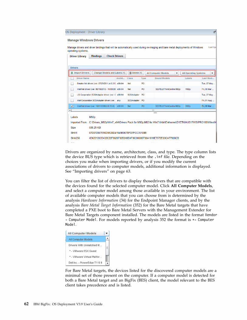
Drivers are organized by name, architecture, class, and type. The type column liststhe device BUS type which is retrieved from the .inf file. Depending on thechoices you make when importing drivers, or if you modify the currentassociations of drivers to computer models, additional information is displayed.See “Importing drivers” on page 63.
You can filter the list of drivers to display thosedrivers that are compatible withthe devices found for the selected computer model. Click All Computer Models,and select a computer model among those available in your environment. The listof available computer models that you can choose from is determined by theanalysis Hardware Information (34) for the Endpoint Manager clients, and by theanalysis Bare Metal Target Information (352) for the Bare Metal targets that havecompleted a PXE boot to Bare Metal Servers with the Management Extender forBare Metal Targets component installed. The models are listed in the format Vendor- Computer Model. For models reported by analysis 352 the format is *- ComputerModel.
For Bare Metal targets, the devices listed for the discovered computer models are aminimal set of those present on the computer. If a computer model is detected forboth a Bare Metal target and an BigFix (BES) client, the model relevant to the BESclient takes precedence and is listed.
62 IBM BigFix: OS Deployment V3.9 User's Guide

You can also filter driver compatibility by Operating System. Click All OperatingSystems and make your selection. The filtered list displays the drivers that arecompatible with the selected operating system. Using both filters narrows the listfurther to display only the drivers that are compatible with the selected Computermodel and Operating system combination.
Use the advanced search option by typing in the corresponding search box to filterfor specific drivers. You can specify the following:v Driver Name (including the driver version)v Classv Model bind ("Bound Models" column in the Driver Library tab)v Labels (Labels column in the Driver Library tab)v Hardware IDs, which identify the specific device and are displayed in the driver
detailsv Any specific file that is part of the imported driver, including the path that was
specified in the wizard ("Imported From" column in the Driver Library tab).
To change model bindings or labels for a driver, select the driver and click ChangeModels and Labels. You can:v Add one or more labels or delete all labels.v Add other model bindings or delete all current model bindings.
Click OK and save your changes.
To add or modify operating system associations for a driver, click
in thecorresponding row. The details for the selected driver are displayed in the bottomsection of the dashboard. Modify the current associations, and save your changes.
If you modify the driver model or operating system bindings or if you delete adriver, a “pending changes” message displays at the top of the dashboard. You cancommit and finalize these changes by clicking Save Changes or Cancel Changes.An action is created to automatically update any bare metal server with thechanges you have saved.
Importing drivers
To import new drivers, complete the following steps:1. Click Import Drivers.
Chapter 4. Managing Drivers for Windows Deployments 63

2. In the Import Drivers dialog, browse to select a folder from which to importdrivers. Then select the compatible operating systems for which the importeddrivers are to be used. By default, only PCI drivers are imported from thespecified folder. If you want to import only non-PCI drivers, select thecorresponding option. Click Next. The application examines the specified pathto identify and analyze the available drivers.
3. The drivers found in the specified path are displayed:
64 IBM BigFix: OS Deployment V3.9 User's Guide

From this panel you can simply verify if the drivers you want are included inthe specified directory. In this case, after viewing the drivers click Cancel toexit the wizard. To proceed with the import operation, select one or moredrivers from the list and click Next..
4. You can optionally select hardware models to bind to the imported drivers. Ifyou do not bind the drivers to any specific models, they are imported andmanaged using "best match" criteria, after the other drivers that you havebound to specific models. You can optionally assign one or more free text labelsto make the drivers you are importing easily identifiable and to simplify driversearch. The labels and models that you specify are displayed in thecorresponding columns in the Driver Library. Both are optional. If you specifymore than one label, each label must be separated by the “|” (vertical bar)character. Labels are viewed in the corresponding column of the dashboard,with the vertical bar separating each label. Using labels can be useful if you areimporting drivers for models that are not yet deployed in your network. Youcan tag these drivers and easily retrieve them to bind them to your newcomputer models when they are available in your network. When you aredone, click Import.
Chapter 4. Managing Drivers for Windows Deployments 65

5. The import results are displayed for each driver you selected, as well as thedetails.
Click OK
6. The Import Drivers Summary is displayed. You can view how many driverswere uploaded. If a driver was already found, its applicability is updated withthe information you supplied.
66 IBM BigFix: OS Deployment V3.9 User's Guide

Note:
v As a best practice, import smaller folders of drivers all at the same time. Thisallows for easier assigning of manual OS and model compatibility and alsoavoids importing unnecessary drivers. The memory limit for importingdrivers requires that the size of the folder to be imported does not exceed theavailable system memory.
v Drivers that were imported with OS Deployment Version 3.6 or earlier donot have any model bindings defined. These drivers are bound at run timeusing a best match criteria. You can add these associations manually byusing Change Models and Labels. If you have one or more driver packagesthat were imported with earlier versions, you can reimport the same driverpackages (without deleting the existing ones) specifying the models that youwant to bind at import time. The driver applicability will be updated and thenew model binding mechanism is used during deployment.
When drivers are imported, an automatic action is created to update the drivermanifests on any bare metal server with the change in drivers.
The drivers are imported as soon as the following action, Update Driver Manifestson Bare Metal Servers, completes:
Note: Importing drivers from a network share can take longer than importingthem from a local folder.
Non-PCI driver management
You can manage non-PCI "Server-Site Installation" drivers. From the Driver Library,you can import non-PCI drivers. You can also tag non-PCI drivers by binding themto specific computer models. However, these model bindings are not used at runtime during deployments. To use non-PCI drivers during a deployment, you must
Chapter 4. Managing Drivers for Windows Deployments 67

manually bind the drivers to the image that you want to deploy from the Bindingstab. If you do not manually bind them, they are not used during deployments.
Managing Windows driver bindingsBefore you deploy an image to a computer, you must ensure that the correctdrivers for the devices on the computer are downloaded during the deployment.
In the Bindings tab of the Driver Library dashboard, you can view the devicedrivers that are used when the selected image is deployed on the selectedcomputer model. This is useful to evaluate in advance which device drivers aremissing and prevent image deployment failures.
From the menu, choose an image file to be deployed and a hardware model onwhich you want to deploy the image, and click Generate Binding Grid. A bindinggrid is created and displayed in the Driver Bindings table. You can view thedrivers that are bound. for each device pertaining to the selected model and image.You can also generate a binding grid for Windows Preinstallation Environments(WinPE) images by selecting the WinPE version and computer model from themenu.
The binding grid displays for each device name the following information:
In the Driver Bound column, the possible values for the status are:
Built-inIndicates that the support for the device is already included in the imageby default.
A driver is listedIndicates that this type of driver is used.
68 IBM BigFix: OS Deployment V3.9 User's Guide

No applicable drivers foundIndicates that there is no driver available. In this case, ensure that youimport the appropriate drivers for your device from the Driver Librarytab.
The Current Manual Binding column displays any drivers that were manuallyselected by editing a device in the binding grid.
At run time, OS Deployment selects the drivers that are the best match for theselected image/model combination. However, if you have bound a driver atimport time to a computer model, this binding has precedence over the defaultbest match (auto) mechanism.
You can edit the driver bindings for a specific device by clicking
.
You can change the following options.
Auto Automatically selects the driver (best match) and is the default option.
Select DriversAllows you to select the drivers that you want to include in thedeployment from a list of compatible drivers for the specific device. Thedrivers you select are displayed in the "Current Manual Binding" columnof the binding grid.
Don't Use DriversAllows you not to associate any driver to the device.
You can refresh the generated binding grid to include the changes that you havemade by clicking the corresponding button.
Chapter 4. Managing Drivers for Windows Deployments 69

Click Add Driver to select additional drivers for those devices that do not providea Device ID. The manually added device drivers are provided to the OS Installerwhen installing the operating system. If you add a driver, it takes precedence overthe model binding that you specified at driver import time.
You can bind drivers to WinPE images if your MDT Bundle is at version 3.8 orlater and you have selected to overwrite existing WinPEs when you upload theMDT Bundle. The Bare Metal OS Deployment server must be at version 7.1.1.19 orlater.
At run time, OS Deployment selects the drivers that are the best match for theselected image/model combination. However, if you have bound a driver atimport time to a computer model, this binding has precedence over the defaultbest match (auto) mechanism.
Checking driver availabilityBefore you deploy images to computers in your network, you can verify that thedrivers you need for the installed devices are available, and, if necessary importmissing drivers selectively.
From the Check Drivers tab of the Driver Library dashboard, you can checkdriver availability for any single image and computer model in your environmentor for all images and computer models. If specific device drivers are missing, youcan import them directly. Only PCI drivers are checked.
Select an image and a computer model from the list, or all images and computermodels. and click Run Driver Check.
By default, the check is processed on critical drivers only. Deselect this option toalso include non-critical drivers. Depending on the size and diversity of the
70 IBM BigFix: OS Deployment V3.9 User's Guide

hardware models and operating system images in your network, the process ofchecking all images and models can take a few minutes to complete.
The result of this check is a list of devices for which the related drivers are eithernot available or were explicitly excluded from deployment when you generated thebinding grid. In the Driver Status column, different icons display the status of thedriver for each of the listed devices:
v The driver is missing for a critical device (typically network or diskdrivers).
v The driver is missing, but the device is not a critical device.
v The driver for this device exists, but the user manually excluded the driverfrom the binding grid.
For each device listed you can complete a remediation action. To import a missingdriver, select a device from the list and click Import Drivers. In the import wizard,specify the folder from which to import the driver. The import process selectivelysearches and displays only the driver or drivers that are compatible for the chosendevice, image, model and architecture. You can also double click the device toopen the import wizard.
If the driver for the listed device exists but the binding was disabled by the user,click the Bindings tab, select the image and computer model to generate thebinding grid, and manually bind the driver to include it in the deployment.
Chapter 4. Managing Drivers for Windows Deployments 71

72 IBM BigFix: OS Deployment V3.9 User's Guide

Chapter 5. Managing Linux OS Resources and DeploymentMedia
You can import Linux OS Resources needed to create network boot media and tocapture and deploy Linux images
Importing Linux OS Resources
Linux OS Resources are required to capture Linux reference machines and to createnetwork boot media for Linux deployments. From the Bundle and MediaManager dashboard, click the corresponding button in the Deployment Resourcestab. Browse to the fully qualified path of the Linux ISO file from which the OSResource will be imported, and click OK. When the action completes, the Linux OSResource is displayed in the list. To delete a Linux OS Resource entry, select it andclick Delete.
Creating network boot media for Linux targets
To create Linux network boot media, complete the following steps:1. From the Bundle and Media Manager dashboard, import a Linux OS Resource
by clicking the corresponding button. Select the fully qualified path to the ISOfile. The supported ISO files are RedHat Enterprise Linux (RHEL) Release 6, 7,or SUSE Linux Version 12. If you have already imported Linux OS Resourcesfor these platforms skip this step.
2. From the Linux Media tab, click Create Deployment Media. the Mediacreation wizard is displayed. Select the OS Deployment Server where the mediawill be created, and click Next.
3. Select or specify the following:a. The Linux OS Resource to be included in the media. You must have
previously imported the resource.b. Specify the fully qualified path on the OS Deployment Server where the ISO
file for the media will be createdc. In the Server Settings section, specify the IP address and the administrative
user password of the OS Deployment Server to which the target connects atboot time. This server can be the same or a different OS Deployment serverfrom the one you are creating the media on. Alternatively, you can specifythe connection parameters at boot time, by checking the correspondingoption.
d. Select the type of network configuration settings that are assigned to theclient at boot time. By default, a dynamic IP address is assigned (DHCP).Alternatively, you can specify a static IP address, network mask, andgateway address. If you specify static network settings, you can overwritethem at boot time by checking the corresponding option.
e. You can optionally specify to have the user start the boot sequence on thetarget. In this case, a prompt is displayed on the target and the bootsequence begins only when the user responds to the prompt.
.4. When you have completed your selections, click OK. The information that you
provided is validated before the media creation task begins.
© Copyright IBM Corp. 2010, 2016 73
|
|
|
||
|
|||||||
|
|
|||||
|||
|
||
||
||||||
|||||
|||
|
||

Important: If you want to deploy a Linux setup image in multicast from networkboot media, the Linux OS resource that you include in the media must be of thesame major version of the image that you are deploying. For example, you can usea RedHat Enterprise Linux (RHEL) Version 7 Update 1 resource to deploy allRedHat Enterprise Linux (RHEL) Version 7 setup images using multicastcommunication.
Network boot media limitations: The following restrictions apply to network bootmedia:v Only CD/DVD media are supported.v Deployment of the media on UEFI targets is not supported.
74 IBM BigFix: OS Deployment V3.9 User's Guide
||||||
||
|
|
|

Chapter 6. Managing Images
The Manage Images and Drivers node includes tasks to capture, import andmanage images for deployment to targets.
You can capture images for Windows and Linux targets, and import images forWindows, Linux and VMWare deployments. The topics in the following sectionsdescribe how to complete these steps for the operating systems that you plan todeploy.
Capturing Windows ImagesWhen you capture an image, you are creating an image that can be customizedand applied to other computers in your network.
Capturing an image involves a set of tasks that result in the creation of a genericimage that can be applied on any computer. The process of capturing an image canaffect the product activation of the captured system. To avoid this problem, youmust capture an image from a virtual machine with snapshot restoration capability.
During the capture phase, the machine you are capturing must be a member of aworkgroup and cannot be in a domain, because the Sysprep tool runs only onmachines in a workgroup.
The captured image is stored on a network share, ready to be uploaded to theserver into the Image Library.
Because captured images are firmware independent, you can deploy (for reimagingor Bare Metal), images that are captured from BIOS machines to UEFI machinesand vice versa.
From the Capture wizard, you can specify SMB share information and choosecapture options. Access the wizard from the Manage Images and Drivers node inthe navigation tree.
The Capture wizard is organized into two sections:v Specify SMB Share informationv Choose Capture Options
© Copyright IBM Corp. 2010, 2016 75
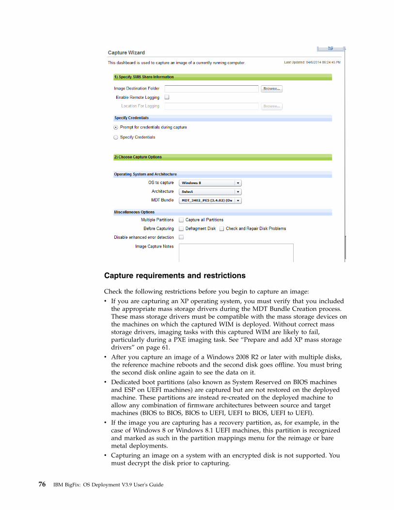
Capture requirements and restrictions
Check the following restrictions before you begin to capture an image:v If you are capturing an XP operating system, you must verify that you included
the appropriate mass storage drivers during the MDT Bundle Creation process.These mass storage drivers must be compatible with the mass storage devices onthe machines on which the captured WIM is deployed. Without correct massstorage drivers, imaging tasks with this captured WIM are likely to fail,particularly during a PXE imaging task. See “Prepare and add XP mass storagedrivers” on page 61.
v After you capture an image of a Windows 2008 R2 or later with multiple disks,the reference machine reboots and the second disk goes offline. You must bringthe second disk online again to see the data on it.
v Dedicated boot partitions (also known as System Reserved on BIOS machinesand ESP on UEFI machines) are captured but are not restored on the deployedmachine. These partitions are instead re-created on the deployed machine toallow any combination of firmware architectures between source and targetmachines (BIOS to BIOS, BIOS to UEFI, UEFI to BIOS, UEFI to UEFI).
v If the image you are capturing has a recovery partition, as, for example, in thecase of Windows 8 or Windows 8.1 UEFI machines, this partition is recognizedand marked as such in the partition mappings menu for the reimage or baremetal deployments.
v Capturing an image on a system with an encrypted disk is not supported. Youmust decrypt the disk prior to capturing.
76 IBM BigFix: OS Deployment V3.9 User's Guide
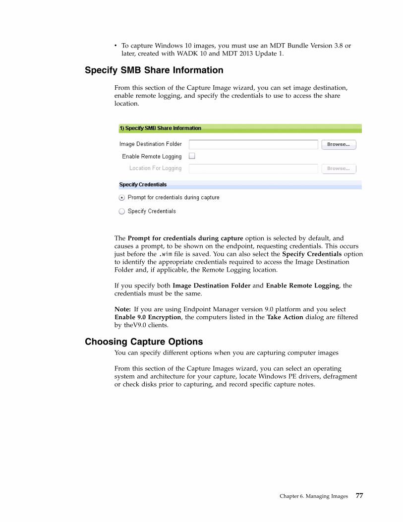
v To capture Windows 10 images, you must use an MDT Bundle Version 3.8 orlater, created with WADK 10 and MDT 2013 Update 1.
Specify SMB Share Information
From this section of the Capture Image wizard, you can set image destination,enable remote logging, and specify the credentials to use to access the sharelocation.
The Prompt for credentials during capture option is selected by default, andcauses a prompt, to be shown on the endpoint, requesting credentials. This occursjust before the .wim file is saved. You can also select the Specify Credentials optionto identify the appropriate credentials required to access the Image DestinationFolder and, if applicable, the Remote Logging location.
If you specify both Image Destination Folder and Enable Remote Logging, thecredentials must be the same.
Note: If you are using Endpoint Manager version 9.0 platform and you selectEnable 9.0 Encryption, the computers listed in the Take Action dialog are filteredby theV9.0 clients.
Choosing Capture OptionsYou can specify different options when you are capturing computer images
From this section of the Capture Images wizard, you can select an operatingsystem and architecture for your capture, locate Windows PE drivers, defragmentor check disks prior to capturing, and record specific capture notes.
Chapter 6. Managing Images 77

Start by selecting the operating system and architecture of the computer you wantto capture. For Windows XP you must also specify the service pack that yourequire.
Choose the MDT Bundle to be used during the capture process. MDT Bundles arefiltered based on which bundles are compatible with the chosen operating system.
You can capture multiple partitions in a single .WIM file, to enable the support ofmulti-partition master images. An MDT Bundle 3.1 or later is required to capturemultiple partitions.
In the Miscellaneous Options section, you can:v Choose to capture multiple partitions by checking Capture all Partitions.v Choose to defragment or check and repair disk problems before capturing by
selecting the corresponding option.v Choose to prevent modifications to the target boot sequence during the capture
process by selecting Disable enhanced error detection. For more informationabout this option, see “Enhanced error detection” on page 96.
v Include capture notes in the available field.
After selecting all capture options, click Capture Image. In the Take Action dialog,target the computer to be captured. When the action is complete, the capturebegins.
Note: This process can affect the product activation of the captured system,making it unable to reactivate. You must capture an image from a virtual machinewith snapshot restoration capability.
78 IBM BigFix: OS Deployment V3.9 User's Guide

Capturing Linux imagesYou can capture a Linux system to create a reference image that can be deployedto bare metal targets.
To capture a Linux system use the Linux System capture task (ID 201).
The capture task is supported for the following operating systems:v RedHat Enterprise Linux Versions 6, 7v SUSE Linux Enterprise Server (SLES) Version 12
Complete the required fields in the form and take action:
Linux OS ResourceYou must have previously imported a Linux OS Resource. If you arecapturing a RedHat Enterprise Linux system, the OS resource must beRHEL Version 7, even if you are capturing a version 6 system. For SUSEEnterprise Linux systems, you must specify a SLES Version 12 OS resource.To import a Linux OS Resource, see Chapter 5, “Managing Linux OSResources and Deployment Media,” on page 73.
Destination folder on network shareSpecify the folder on the network share where the files created by thecapture task are stored. The network share folder must be specified in theform //<IP Address>/<drive_name>, for example //192.168.1.232/shared.The task creates the following files:v The image files from the captured system (.lim)
Chapter 6. Managing Images 79
|
||
|
|
|
|
|
|
|
|||||||
|||||
|

v The file containing information about the captured image (.imageinfo,such as operating system, service pack number, and locale, amongothers.
v The partition information of the captured system (.ini). Thisinformation is displayed in the bare metal profile, in the Partition editorsection.
User for Network ShareSpecify the user to access the network share
Password for Network shareSpecify the password to access the network share
Security mode Select the authentication protocol that must be used to access the networkshare. The default is ntlm.
Boot time hardware parametersSpecify any boot time parameters to be provided to the installer.
Important: When you prepare your reference machine for the capture task, youmust ensure that one of the primary partitions is flagged as bootable.
After you have successfully captured your Linux system, you must import theimage into the Image Library, and create a bare metal profile to deploy thecaptured image. For further details, see “Importing images,” and “Creating BareMetal Profiles for Linux Images” on page 130.
Requirements and limitations
The following limitations apply to the Linux capture task:v Btrfs file system is not supported.v LVM thin provisioning is not supported.v If you are capturing a SUSE Linux Enterprise (SLES) 12 system, it must have at
least 200 Megabytes of free space in a non-LVM partition.v 32-bit physical machines are not supported.v You can capture 32-bit operating system images running on 64-bit physical
machines, but you must use a 64-bit OS resource.v Capture of LVM volume groups (VG) on multiple physical disks is not
supported.
Importing imagesThe Image Library Dashboard allows you to manage images by importing,pre-caching, deleting, and modifying the metadata of your existing images.
From the Image Library, you can upload the following images:v Windows images that have been previously captured with either the Capture
dashboard or manually. (.wim), or images uploaded directly from installationmedia . You cannot import images from installation media (ISO) for WindowsXP or Windows 2003 platforms.
v Linux images that you have captured using task 201, or created from installationmedia (setup).
v VMware ESXi images created from installation media.
80 IBM BigFix: OS Deployment V3.9 User's Guide
|||
|||
||
||
|||
||
||
||||
|
|
|
|
||
|
||
||
|
||

You can also import images in RAD format. Unlike other images, RAD imagescannot be deployed to targets through the binding menu. You cannot create BareMetal profiles based on RAD images from the Image Library dashboard. Fromthese images you create RAD profiles for deployments using Server Automationplans. For more information, see Appendix B, “Bare Metal OS Provisioning usingRAD Profiles,” on page 183.
For Windows images only, you can copy configuration settings from an existingimage to a newly imported image, providing they are compatible. For example, ifyou have uploaded a new image for an Operating System update, you canassociate to it any Bare Metal Profiles, driver bindings, and templates that weredefined in an existing image of an earlier service pack of the same OperatingSystem. See “Copying configuration settings from a Windows reference image” onpage 83.
From the Image Library, you can deploy the images to selected targets, or createprofiles to send to Bare Metal OS Deployment Servers for deployments onWindows and Linux targets.
The Origin column displays whether the image was captured (Capture) orimported from installation media (Setup). Linux and VMware images are identifiedby the extension .lim.
To import a new image, click Import Image. Use the icons on the right to eitherdownload or edit an existing image in the library.
In the import image menu, select the type of image you want to import. You canimport images captured from a Windows (.wim) or Linux (.lim) reference machine,a RAD format image, or images from installation media (ISO).
Important: Reimaging is not supported on WMware ESXi targets.
Importing images from installation media
ISO images can be imported in archive format (.iso) or from a folder or drivewhich contains the uncompressed ISO image files. If you are importing Windowsimages in ISO archive format (.iso), you must have previously downloaded andinstalled the 7-zip compression/decompression tool on the system where theConsole is installed.
If the image you are importing is provided in more than one installation mediafile, for example in SLES-DVD1.iso and SLES-DVD2.iso, you must uncompress thefiles into a single folder, and specify that folder in the Import image popup.
Chapter 6. Managing Images 81

Browse to locate the image file or folder on your computer and click Analyze.
The analysis typically takes several minutes to complete. During this time, if youare importing an ISO image, the contents of the specified ISO file or folder arechecked and the information retrieved from the image is displayed. In the EditionsList, you can view the editions you can deploy. Check the information and clickOK to begin importing the image, or Cancel to quit.
Importing captured Windows images
You can import images that you have previously captured using the Capturedashboard or that you have captured manually. During the import of a captured.wim image file, the corresponding driver descriptor file (.driverinfo) and imagedescriptor file (.imageinfo ) that were created during the capture phase, must existin the same path. If the driver descriptor file is missing, the import process
82 IBM BigFix: OS Deployment V3.9 User's Guide
|
|||||

automatically creates it. If the image descriptor file is missing, you are prompted tospecify the required fields. For manually captured images, you must provide therequired information:
Important: If you import a manually captured image containing multiplepartitions, only the first partition found in the image (zero-indexed) is considered.
Importing captured Linux images
To import a Linux image that you have previously captured using task 201, clickImport image, select Linux captured image (.lim) and specify the fully qualifiedpath to the captured image. Click Analyze . When the analysis completes, theimport process begins. Click OK.
Copying configuration settings from a Windows reference image
For Windows images, you can copy configuration settings such as Bare MetalProfiles, templates, and driver binding grids, from an existing image to anothercompatible image. The configuration settings are copied only if the followingcompatibility conditions are met:v Both images must:
– be of the same Operating System– have the same architecture (32-bit or 64-bit)– have the same origin (both must be either captured images or created from
installation media).
Chapter 6. Managing Images 83
|||
|
||

v The image that inherits the settings must not already have configuration settingsassociated to it.
If one or more of the conditions above are not satisfied, an error message is issued.
From the Image Library dashboard, select the target image on which you want tocopy the configuration settings and click Copy Settings from....
Choose the reference image from the list of compatible images. If the referenceimage has Bare Metal profiles associated to it, you can optionally specify a prefix, asuffix, or both for the profile names to be used when they are copied on the targetimage.
Note: If you have specified either a prefix, suffix, or both, and the resulting profilename exceeds 70 alphanumeric characters, the name is shortened to the maximumallowed length.
If the reference image has templates and driver bindings associated to it, these arealso copied to the new image. You can change profile names in the new image. Asummary panel displays all objects that are copied.
Important: If there are rules associated to the Bare Metal Profiles in the referenceimage, these rules are copied to the new image but they are disabled, so as toavoid conflicts with the old profiles. To reactivate them in the copied Bare Metalprofiles, use Activate Rule. After the copy has completed, the reference image andconfigurations are not erased.
Note: In some cases, you might receive an error message even if the target imagedoes not have any previously defined settings. For more information, see “Copyimage settings error on manual driver bindings” on page 174.
84 IBM BigFix: OS Deployment V3.9 User's Guide
Chapter 7. Reimaging
Reimaging is the process of saving the user state on a computer, installing a newimage on it, and then restoring the user state.
You can reimage Windows or Linux systems by choosing previously uploadedimages from the Image Library.
When you reimage a computer you can upgrade the operating system or install alater service pack, but you cannot downgrade architectures or operating systems.For example, you cannot reimage from Windows 7 to Windows XP (independentlyof the architecture), and you cannot deploy a 32-bit image on a target running a64-bit operating system.
On Windows systems, you cannot reimage a server class operating system to aclient class operating system and vice-versa.
On Windows systems, reimaging can be completed using multicast distribution ifyour network infrastructure supports it. To reimage in multicast, the targets mustbe connected to relays that are also Bare Metal Servers, and at least one reimageprofile must be available for the image you want to deploy.
Reimaging a Linux system means refreshing the Operating System on a computerwith an active IBM BigFix Client. The machine identity is preserved during themigration.
On Linux systems, reimaging requires the Linux Image provider component whichyou must install on those relays that manage the targets that you want to reimage.If the Linux targets are connected to a relay that is a Bare Metal Server, thiscomponent is not needed. To install and use this component, see “Managing theLinux Image provider” on page 21.
From the Image Library Dashboard, choose a source image and click Deploy toComputer.
In the dialog, you can customize a variety of settings and options and createdeployment actions that reimage a computer with the specified settings. You cansave the customized options as a template that you can use again in the future.The reimaging process on a Endpoint Management client creates multiple actionsto download and customize all files needed. When the download is complete,reimaging begins. The status on the Endpoint Management Console is visible atthe end of the reimage process, when the new operating system is successfullystarted.
© Copyright IBM Corp. 2010, 2016 85

Depending on whether you are reimaging Windows or Linux, the options you cancustomize are described in “Reimaging Windows Systems”, “Reimaging WindowsSystems in multicast” on page 102, and “Reimaging Linux Systems” on page 106.
Reimaging Windows SystemsYou can specify different options which will affect the reimaging process on thetarget.
The reimaging process on Windows systems does not re-partition the disk on thetarget system. To reimage a computer successfully, ensure that on the targetmachine the available free disk space is at least equal to or greater than the Sizeon disk of the image you are deploying.
You can reimage Windows targets in multicast, using either captured images orISO images. To complete this task see “Reimaging Windows Systems in multicast”on page 102.
To reimage a Windows system from the Image Library, you have these options:v Edit an image that was previously imported, and deploy it to one or more
targets.v Deploy an image that you previously captured from a reference machine. In this
case, if you have saved the user state on the captured system, you can restore iton the system you are reimaging.
v Deploy an image that was created from installation media (ISO image).
You can use the Search box to search by a specific image name. Select an image byclicking the appropriate row in the table.
Editing an image
You can also edit an image by selecting it and clicking . In the Edit Imagewindow, you can change the image information.
86 IBM BigFix: OS Deployment V3.9 User's Guide

Note: Some fields cannot be modified if there are one or more bare metal profilescreated from or associated to the image.
If you expand the Partition Mappings subsection, which is closed by default, thefollowing information is displayed:v The drive letter of the partition.v If the partition is bootable.v If the partition is a system partition.v Additional information about the partition, for example if it is a recovery
partition.v The size of the partition.
In this subsection, you can edit partition mappings for the computers to which theselected WIM image is to be applied.
Note: Both disk and partition numbers are zero-indexed in this view.
Chapter 7. Reimaging 87
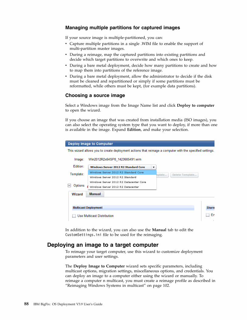
Managing multiple partitions for captured images
If your source image is multiple-partitioned, you can:v Capture multiple partitions in a single .WIM file to enable the support of
multi-partition master images.v During a reimage, map the captured partitions into existing partitions and
decide which target partitions to overwrite and which ones to keep.v During a bare metal deployment, decide how many partitions to create and how
to map them into partitions of the reference image.v During a bare metal deployment, allow the administrator to decide if the disk
must be cleaned and repartitioned or simply if some partitions must bereformatted, while others must be kept, (for example data partitions).
Choosing a source image
Select a Windows image from the Image Name list and click Deploy to computerto open the wizard.
If you choose an image that was created from installation media (ISO images), youcan also select the operating system type that you want to deploy, if more than oneis available in the image. Expand Edition, and make your selection.
In addition to the wizard, you can also use the Manual tab to edit theCustomSettings.ini file to be used for the reimaging.
Deploying an image to a target computerTo reimage your target computer, use this wizard to customize deploymentparameters and user settings.
The Deploy Image to Computer wizard sets specific parameters, includingmulticast options, migration settings, miscellaneous options, and credentials. Youcan deploy an image to a computer either using the wizard or manually. Toreimage a computer n multicast, you must create a reimage profile as described in“Reimaging Windows Systems in multicast” on page 102.
88 IBM BigFix: OS Deployment V3.9 User's Guide

To proceed manually, select the Manual tab to manually edit thecustomsettings.ini file that is generated from fields specified in the Wizard tab.Changes made in the file make fields in the Wizard tab non-editable and manualchanges must be undone to be able to make changes in the Wizard tab again.
Editing the customsettings.ini file incorrectly might cause failure during theimaging process. Some settings of this file are not present in this tab because theyare handled separately by encryption. Specifically, these settings are:v DomainAdmin
v JoinDomain
v DomainAdminDomain
v DomainAdminPassword
v MachineObjectOU
For these values, the settings in the Wizard tab take precedence over the settingsfound in the Manual tab.
From the wizard, you can optionally create a baseline that can be reused forsubsequent reimage deployments:
When you take action from the baseline, and provide the necessary credentials,multiple action groups are created and the activity dashboard is updated with newentries.
Expand Options to edit the settings for the reimage. When you have made therequired changes, you can save the template, and either create a reimage action byclicking Reimage computer or create a reusable baseline by clicking CreateBaseline.
Each component of the Wizard tab is explained in the following sections.
Chapter 7. Reimaging 89

Requirements and limitations
The reimaging process is influenced by different components, such as source anddestination operating systems, the MDT Bundle used, and by user and domainsettings. One or more of the following requirements or restrictions may apply,depending on your specific selection:1. You cannot reimage a system with an encrypted disk. You must decrypt the
disk before deploying the image on the target system, or else the reimagingfails.
2. When you deploy a captured image, if the BES client version installed on thetarget computer is earlier than the version contained in the image, thereimaging completes successfully. However, if you upgrade the BES client onthe target computer at a later time using the upgrade Fixlet, this operationmight fail. To solve the problem, manually upgrade the client on the targetwhere the upgrade has failed by using the Repair option.
3. You cannot reimage a Server class operating system on a client class operatingsystem or vice-versa.
4. Reimaging to Windows 10 requires MDT Bundle version 3.8.12 or later, createdwith WADK 10 and MDT 20'13 Update 1. The source operating system musthave IBM BigFix client version 9.2.5 or later installed before you start thereimaging process.
5. If you are reimaging Windows 7 to Windows 7, using MDT Bundle 3.8.12 orlater, created with WADK 10 and MDT 2013 Update 1, The migrate usersettings option is not supported.
90 IBM BigFix: OS Deployment V3.9 User's Guide

Windows License Product Key
Enter a valid Windows license product key in this field. To deploy multiple copiesof Windows, you must have a volume key.
Note: If you fail to specify a correct product key, this might result in a failedre-image job and put the computer in an unrecoverable state.
Migrate User SettingsYou can capture the user profiles and settings of a system before the reimagingprocess begins.
The Migrate User Settings capability captures multiple user profile directories froma system about to be reimaged. In most cases, the profile data stays on themigrated system. However, if the migration is from Windows XP to Windows XPand the system does not have sufficient disk space to duplicate the migratedprofiles, the data might overflow to a "USM Overflow Location" (SMB) and berestored to the system after the image task is complete. To avoid filling up youravailable storage on the specified USM Overflow location, perform multiplemigrations.
The users defined on the computer that you are reimaging and that do not alreadyexist in the image that you are deploying, are migrated and set to disabled on thereimaged computer. You must enable them again by using the“ ComputerManagement” option of the Administrative tools. Alternatively, if you want themigrated users to be enabled during the deployment process, follow these steps:1. In the Image Library, select the image you want to deploy and click Deploy to
Computer
2. In the Deploy Image to Computer pane expand the Options section3. Select the Manual tab and scroll to USM Settings4. Modify the value of the LoadStateArgs parameter as follows:
LoadStateArgs=/lac /lae
The restored users will have an empty password which must be changed at firstlogon.
Note that by adding these values in the LoadStateArgs parameter, the restoredusers that were disabled in the source operating system (and that do not alreadyexist in the image you are deploying) will be enabled in the final operating system.For more information about editing parameter values for capturing (ScanStateArgs) and restoring (LoadStateArgs ) user settings in the Manual tab, see thedocumentation at the following links: http://technet.microsoft.com/en-us/library/
Chapter 7. Reimaging 91

cc749015%28v=ws.10%29.aspx (ScanState) and http://technet.microsoft.com/en-us/library/cc766226%28v=ws.10%29.aspx (LoadState).
Note:
You cannot migrate user settings for server class operating systems. When youselect server class operating systems, this option is disabled.
User State Migration behavior and capabilities might vary based on the originaloperating system, new operating system, or amount of storage space.
From / ToWindowsXP
WindowsVista Windows 7 Windows 8
Windows8.1
Windows10
WindowsXP
Uses localstoragespace tocopyprofile
Potentialdisk impact
Use localrelay forcompressedstorage ifcomputerhasinsufficientspace (atcost ofnetworkimpact)
Uses “hardlink” tomigrateprofilelocally
No disk ornetworkimpact
Uses “hardlink” tomigrate theprofilelocally
No disk ornetworkimpact
Uses “hardlink” tomigrate theprofilelocally
No disk ornetworkimpact
Notsupported
Notsupported
WindowsVista
Notsupported
Uses “hardlink” tomigrateprofilelocally
No disk ornetworkimpact
Uses “hardlink” tomigrate theprofilelocally
No disk ornetworkimpact
Uses “hardlink” tomigrate theprofilelocally
No disk ornetworkimpact
Notsupported
NotSupported
Windows 7 NotSupported
NotSupported
Uses “hardlink” tomigrate theprofilelocally
No disk ornetworkimpact
Uses “hardlink” tomigrate theprofilelocally
No disk ornetworkimpact
Uses “hardlink” tomigrate theprofilelocally
No disk ornetworkimpact
Uses “hardlink” tomigrate theprofilelocally
No disk ornetworkimpact
92 IBM BigFix: OS Deployment V3.9 User's Guide

From / ToWindowsXP
WindowsVista Windows 7 Windows 8
Windows8.1
Windows10
Windows 8 NotSupported
NotSupported
NotSupported
Uses “hardlink” tomigrate theprofilelocally
No disk ornetworkimpact
Uses “hardlink” tomigrate theprofilelocally
No disk ornetworkimpact
Uses “hardlink” tomigrate theprofilelocally
No disk ornetworkimpact
Windows8.1
NotSupported
NotSupported
NotSupported
NotSupported
Uses “hardlink” tomigrate theprofilelocally
No disk ornetworkimpact
Uses “hardlink” tomigrate theprofilelocally
No disk ornetworkimpact
Windows10
NotSupported
NotSupported
NotSupported
NotSupported
NotSupported
Uses “hardlink” tomigrate theprofilelocally
No disk ornetworkimpact
Miscellaneous OptionsIn the Deploy Image to Computer dashboard, you can specify a set of options tocustomize the deployment for your specific environment.
Use the Miscellaneous Options section of the dashboard to specifyenvironment-specific options to be used for the deployment.
Use the System Tag field to set a string in the registry file to highlight somethingspecific for that system to the IBM BigFix platform. For example, it could indicatethat this system has been newly imaged. A registry entry with name SystemTag andthe specified value is created under the keyHKEY_LOCAL_MACHINE\SOFTWARE\BigFix\EnterpriseClient\ImageInfo
Chapter 7. Reimaging 93

orHKEY_LOCAL_MACHINE\SOFTWARE\Wow6432Node\BigFix\EnterpriseClient\ImageInfo
depending on the architecture of the machine. You can then create an action usingthe SystemTag registry key and its value as relevance to apply your action andreset that key as the first step of your action to prevent it from being run twice.
Note: This field is deprecated and is kept for backward compatibility only. If youwant to identify computers or groups of computers in your network by assigningvariables, use the Client Settings field.
You can specify Client Settings to list named variables that are assigned to thedeployed computer. The values you assign can be used either as labels to identifycomputers with specific roles or as filters in Fixlet actions and in Fixlet relevance toexclude an action on a target. You must specify the variables in a NAME:VALUEformat. If you specify multiple variables, each one must be separated by a verticalbar “|”.
After a deployment, you can display these values in the IBM Endpoint Managerconsole by selecting the specified computer, and clicking “Edit Computer Settings”.The settings are listed under “Custom Settings.”
Note: During a system migration, preexisting client settings are retained andrestored in the new operating system. Using this feature, you can extend themigrated target with new client settings.
Examples of how you can use the client settings field to configure the target after adeployment are available on the BigFix wiki at this link: https://www.ibm.com/developerworks/community/wikis/home?lang=en#!/wiki/Tivoli%20Endpoint%20Manager/page/Using%20the%20Client%20Settings%20field%20to%20configure%20targets%20during%20deployments.
A complete list of available client configuration (custom) settings, and a descriptionof how to use them is available at this link: https://www.ibm.com/developerworks/community/wikis/home?lang=en#!/wiki/Tivoli%20Endpoint%20Manager/page/Configuration%20Settings?section=Clients/library/cc749015%28v=ws.10%29.aspx
Select Enable Administrator to enable the Administrator account on the targetsystem during the deployment process of captured images.
94 IBM BigFix: OS Deployment V3.9 User's Guide

When you deploy images created from installation media (ISO), the Administratoruser is always enabled and you must always supply the corresponding password.For further information about enabling users, see “Migrate User Settings” on page91.
Setting Secure Password Transfer
If you are using BigFix version 9.0 or later on the server and clients, You canenable the encryption method by selecting Enable 9.0 Encryption in theEncryption type field. This selection requires no further actions, but the take actiondialog will be filtered by the V9.0 clients, an SSL encryption which requires publicand private keys to be generated, or no encryption of passwords.
If you choose to use SSL encryption and you have BigFix version 8.2, you mustperform the following steps:
Select Enable SSL Encryption. If your BigFix server is at version 9.0 or later, thisoption does not apply.
1. Activate the SSL Encryption Analysis, which is located in the Setup node in thenavigation tree. The SSL Encryption Analysis is needed only for encryptingactions to BigFix clients version 8.2, not for version 9.0 clients. If all clients areat version 9.0 or later, this is not necessary.
Chapter 7. Reimaging 95

2. Run the Enable Encrypted Passwords task on the machines that you want toreimage using a secure password. This Fixlet can be found in the Maintenanceand Configuration node of the navigation tree.
3. After you enable SSL encryption and choose computers to reimage, the SelectEncrypted Endpoints dialog displays. In the list check the computers that youwant to securely reimage, and then click reimage Computer.
Enhanced error detection
OS Deployment modifies the boot sequence of target machines to monitor andtrack operations performed during capture, reimage, and bare metal deployments.This is done by hooking the master boot record (MBR) to detect and handle booterrors and other exceptions such as system crashes, startup failures, and infiniteloops.
You can choose to prevent the modification of the boot sequence during theseoperations by checking Disable enhanced error detection.
Disabling error detection inhibits changes to the boot sequence to avoidinterference with specific target settings or company policies. Checking this optiondoes not affect the deployment process flow and result.
Mapping partitions
Click Edit Partition Mapping to choose the partition layout for the deployment.This option is enabled only for captured images with more than one partition.
In the Partition Editor, the partitions contained in the WIM image are associatedwith the partitions that are present on the target computer. You map the capturedpartitions into existing partitions and decide which target partitions to overwriteand which ones to keep.
You can maintain partitions previously created on the physical disk. These are kepteven after creating the new associations.
96 IBM BigFix: OS Deployment V3.9 User's Guide

The WIM Index column identifies the partitions of the captured image, that youmap to the partitions of the target machine, which are identified by Disk numberand Partition Number in the corresponding columns.
The Info column displays additional information on the partition, for example,whether it is a recovery partition.
The asterisk (*) in the WIM index column indicates that this partition in thecaptured image was marked as bootable at capture time. If you delete thispartition, the system partition is automatically set as bootable.
For example, when reimaging a target from Windows XP (default installation withsingle-partition), to Windows 7 (which has separate boot and system partitions),you must delete the boot partition from your captured Windows 7 image. Thesystem partition is then automatically marked as bootable.
Chapter 7. Reimaging 97

During the reimaging process, regardless of how you map the system and bootpartitions, if the number of partitions in the captured image is greater than thepartitions present on the target machine, the validation fails. Because the reimageprocess does not re-partition the target machine, you must ensure that the numberof mapped partitions is not greater than the partitions defined on the target, orboth the validation step and the reimaging process fail.
If the number of partitions you configure for the target is less than the actualnumber of partitions present on the target, the results of the validation depend onhow the partitions in the image are mapped to the target disk and partition.
It is strongly recommended to reimage ensuring that the number of partitionsmapped from the captured image are equal to the number of actual partitions onthe target.
You can also select the dash character (-) in the WIM Index column, to avoidoverwriting the target partition with the specified partition of the WIM. Forexample, if on a Windows XP target machine you have a data partition that youwant to prevent from being overwritten, you must modify the partition mappingby selecting the dash (-) character in the WIM Index column, so that on thecorresponding target partition , no partition of the WIM image is transferred, asdisplayed in the following panel:
98 IBM BigFix: OS Deployment V3.9 User's Guide

If the target of a reimage is a UEFI machine, a separate boot partition is alwaysavailable at run time, regardless of how the bootable and system partitions aremapped in the WIM.
When you are done, click Validate Mapping to validate your associations.
Note: On BIOS machines only, a maximum of four partitions (primary) aresupported on the same disk. Because images are firmware independent, you candefine more than four partitions on the same disk but the deployment of such animage fails on BIOS machines. This limitation does not apply to UEFI machines.
Share Location for remote logging and USM Overflow
Remote Logging specifies a network location to which your log files are copiedafter capture or re-image. To use this feature, click the Enable box and browse toassign a logging location.
If you enabled remote logging you can also select Dynamic Logging to enable realtime logging for debugging purposes. Logs are created dynamically and stored inthe specified network location.
Enable USM Overflow specifies a network location where user files are to bemigrated if there is insufficient space on the endpoint. This occurs only duringWindows XP to Windows XP migrations. To use this feature, click the Enable boxand browse to assign an overflow location.
Share Location Credentials
Enter user name and password credentials for users to access the shared location.If using both Remote Logging and USM Overflow, the credentials must be thesame.
Chapter 7. Reimaging 99

Domain Credentials
After a deployment, a computer can be joined to a workgroup or to a new orexisting domain.
WorkgroupTo join a computer to a workgroup, specify the name of the workgroup.
Specify DomainTo join a computer to a domain, specify the name of the domain andcredentials with domain-joining privileges. The domain name can containall alphanumeric characters, but none of the following:backslash (\)slash mark (/)colon (:)asterisk (*)question mark (?)quotation mark (")less than sign (<)greater than sign (>)vertical bar (|)
Names can contain a period (.), but cannot start with a period. Youshould not use periods in Active Directory domains. If you are upgradinga domain whose NetBIOS name contains a period, change the name bymigrating the domain to a new domain structure and do not use periods inthe new domain names. You can also specify the DNS domain name, forexample, MyDom or MyDom.MyCompany.com.
Existing DomainTo migrate domain settings from the previous operating system, enter theappropriate domain-joining credentials.
Specify OUTo join a computer to an active directory organizational unit, specify thefull Active Directory path name of the OU to join. Specify the usercredentials with domain-joining privileges.
For example:OU=MyOu,DC=MyDom,DC=MyCompany,DC=com
All characters are allowed, including extended characters. As a bestpractice, use Organizational Unit (OU) names that describe the purpose ofthe OU and that are short enough to be easily managed.
Note: OU settings cannot be specified for a workgroup or domain name.Domain-joining credentials can be specified as a domain name or as a DNSdomain name, as described previously. If the domain is not specified as part of theuser name, the name of the domain to which you are joining is used. Formats suchas [email protected] are not allowed.
The values you specify in the wizard are stored in the CustomSettings.ini file andare mapped as follows:
Table 4. Domain Credentials value mapping in the CustomSettings.ini file
Field in the wizardCorresponding property inCustomSettings.ini file
Workgroup/Domain Name JoinDomain
Organizational Unit to join (OU) MachineObjectOU
100 IBM BigFix: OS Deployment V3.9 User's Guide

Table 4. Domain Credentials value mapping in the CustomSettings.ini file (continued)
Field in the wizardCorresponding property inCustomSettings.ini file
User name (Domain\user login name) DomainAdminDomain and DomainAdmin
Password DomainAdminPassword
IBM BigFix performs the Join Domain using the Microsoft Deployment Toolkit(MDT). Lite Touch Installation (LTI) is used for deployments. LTI uses a commonset of scripts and configuration files (CustomSettings.ini) to deploy the targetcomputers. IBM BigFix automates the domain-join process by modifying theCustomSettings.ini file used for the MDT deployment process. The settings thatyou specify and that are stored in the file, are then parsed by the Window Setupprogram, and the system attempts to join to the domain early in the deploymentprocess.
You can modify the following properties in the CustomSettings.ini file byselecting the Manual tab.
Table 5. Join Domain Properties in the CustomSettings.ini file
Property in CustomSettings.ini file Description
DomainAdmin The user account credentials used to join thetarget computer to the domain specified inJoinDomain. Specify as domain\user_name [email protected]
DomainAdminDomain The domain in which the user's credentialsspecified in DomainAdmin are defined.
DomainAdminPassword The password of the domain Administratoraccount specified in the DomainAdminproperty and used to join the computer tothe domain
JoinDomain The domain that the target computer joinsafter the operating system deployment iscomplete. This is the domain in which thecomputer account for the target computer iscreated. This field can contain alphanumericcharacters, hyphens [-], and underscores [_].Blanks or spaces are not allowed.
MachineObjectOU The Organizational Unit (OU) in the targetdomain in which the account for the targetcomputer is created.
To enable an SSL encryption of domain credentials, select Enable SSL Encryptionand check computers in the dialog. The dialog is filtered by computers that havehad encryption enabled on them with the Enable Encryption for Clients Fixlet inBES Support. Click Reimage. The Take Action dialog is pre-populated with thecomputers that you selected on the previous dialog. You must run the action on allthe selected computers.
Chapter 7. Reimaging 101
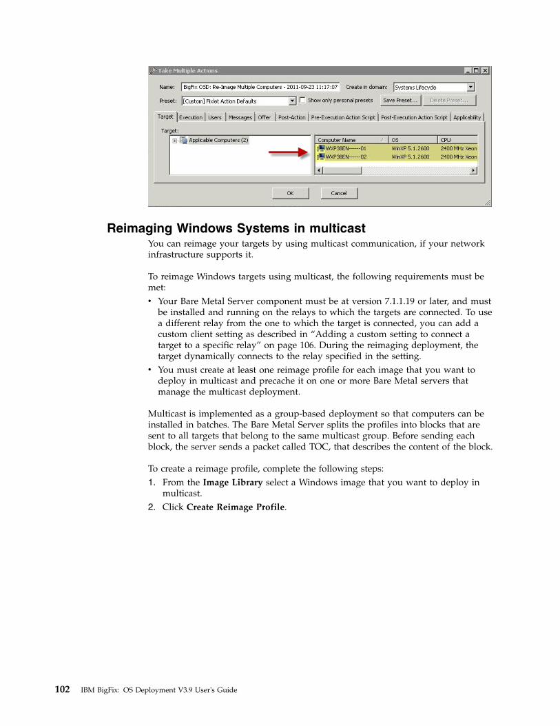
Reimaging Windows Systems in multicastYou can reimage your targets by using multicast communication, if your networkinfrastructure supports it.
To reimage Windows targets using multicast, the following requirements must bemet:v Your Bare Metal Server component must be at version 7.1.1.19 or later, and must
be installed and running on the relays to which the targets are connected. To usea different relay from the one to which the target is connected, you can add acustom client setting as described in “Adding a custom setting to connect atarget to a specific relay” on page 106. During the reimaging deployment, thetarget dynamically connects to the relay specified in the setting.
v You must create at least one reimage profile for each image that you want todeploy in multicast and precache it on one or more Bare Metal servers thatmanage the multicast deployment.
Multicast is implemented as a group-based deployment so that computers can beinstalled in batches. The Bare Metal Server splits the profiles into blocks that aresent to all targets that belong to the same multicast group. Before sending eachblock, the server sends a packet called TOC, that describes the content of the block.
To create a reimage profile, complete the following steps:1. From the Image Library select a Windows image that you want to deploy in
multicast.2. Click Create Reimage Profile.
102 IBM BigFix: OS Deployment V3.9 User's Guide

3. The Reimage Profile properties window is displayed.
To enable multicast for the profile, select the corresponding option. Defaultvalues for multicast deployment are provided. You can accept or change them,depending on the characteristics of your network:
Display NameThe name of the profile. By default, the name is derived from the
Chapter 7. Reimaging 103

associated image and the type of profile (in this case, Reimage). Youcan specify a different name, with a maximum length of 70alphanumeric characters.
MDT BundleThe MDT Bundle to be used for the deployment. You can choose adifferent one from the list of compatible bundles for the selected image.
Multicast ModeDefines how the multicast distribution is managed on the targets atdeployment time for the profile:
Probe and FailIf the probe on the target fails, the deployment task also fails.
Probe and Fall back to UnicastIf the probe on the target fails, deployment of the profile occursin unicast
Force Deployment on the target is forced to multicast regardless ofprobe results.
Group SetupSelect the type of multicast group that is used for the deployment. Youcan accept or change the associated parameters.
Closed GroupTargets join the group as they are ready. When the followingcriteria are satisfied, the group is closed and distributionbegins. This is the default.
Number of targets in groupSpecify the maximum number of targets allowed in thegroup. The default value is 12.
Wait for targets up to minutesSpecify the maximum number of minutes to wait fortargets before starting the multicast deployment. Thedefault value is 10 minutes.
Minimum number of targets in groupSpecify the minimum number of targets that must joinfor a multicast deployment. If the specified value is notreached, deployment is completed in unicast. Thedefault value is 2.
Open GroupTargets can join the group as they are ready, at any time duringdeployment. You can change the associated parameter.
Average number of targets in groupSpecify the average number of targets expected in thegroup. This value is used to optimize blocksynchronization. The closer the number of actual targetsis to this value, the more efficient the multicastdeployment. The default value is 16.
Advanced ParametersMulticast advanced customization and tuning options that apply toboth multicast group types.
Block synchronization wait time in secondsSpecify how many seconds the server must wait before sending
104 IBM BigFix: OS Deployment V3.9 User's Guide

the next block. This value is preset to 120 seconds. If youspecify a value less than 5 seconds, the block synchronizationwait time is forced to 5.
Block size in MBThe image is divided into blocks that are sent to the targets.This parameter sets the maximum size of the data blocks (inmegabytes) sent in each transmission packet. The default valueis 16 Megabytes.
Enable block encryptionSpecify if the blocks must be encrypted during transmission.
4. Click OK to save the profile.5. Select the profile from the list, and click Send to Server. If you select multiple
profiles and more than one server, the send operation might take some time.
To deploy an image in multicast , select it from the list and click Deploy toComputer.
Check the multicast distribution option and select the reimage profile. Specify theother parameters as needed. For a detailed explanation of the parameters see“Deploying an image to a target computer” on page 88.
Probing targets before a multicast deployment
Before deploying images in multicast, you can check if targets in your network canreceive multicast deployments by running the Probe Clients for MulticastDeployment task (80). The task checks that the client can accept incomingmulticast packets. The probe uses an incremental TTL (Time to Live) value up to amaximum default of 5. If you want to change the maximum TTL value that theBare Metal server uses to check if the target is able to receive multicast packets,edit the computer settings of the Bare Metal server and create a new client settingOSD_MaximumTTL_MCastProbe.
Chapter 7. Reimaging 105

To successfully deploy images in multicast, you must ensure that the needed portsare available on the Bare Metal Server and on the targets connected to them. Formore information about the ports that are used for multicast distribution, seeListening ports used for OS Deployment tasks, media creation and reimagingdeployments in multicast..
Adding a custom setting to connect a target to a specific relay
From the Subscribed computers view, highlight the target computer and click EditSettings. Click Add to define the new setting with name BMServerOverride . Setthe value to the hostname or IP address of the relay with the Bare Metal Servercomponent to which the target must connect for the reimaging deployment, thenclick OK to save.
Reimaging Linux SystemsYou can reimage Linux systems by deploying images that you previously importedfrom deployment media.
When you reimage a Linux target system, you are installing an image file (.LIM)previously created from an ISO image and stored in the Image Library. Dependingon the reimaging mode, (Upgrade or Install), you are required to specifyparameters that are needed for the target deployment. The parameters that youspecify must be saved to a template before starting the reimage task. For moreinformation, see “Managing templates” on page 112.
Note: HTTP Access is needed to the Image Provider component, which listens onport 8088. For more information, see “Ports used by the Bare Metal OSDeployment Server” on page 25.
You can reimage Linux systems in two different modes:
Upgrade
If you select this mode, the operating system RPM Package Manager files(.rpm) on the target are updated at the required level. Optionally, you canchoose to upgrade the Endpoint Manager Client that is installed on thetarget.
Install
If you select this mode, the selected image is installed on the target system.The data on the current system is overwritten by the new installation. Thedisks on the target are re-partitioned by default. The following existingsettings on the target are preserved and copied to the reimaged system:v Machine identity (language, keyboard, timezone, network settings)v BigFix client identity
Note: In some cases, the BigFix client identity is not preserved. For moreinformation, see “Duplicate client computer entry in the Server databaseafter a Linux reimage” on page 173.
Important:
v Reimaging to targets that are managed by a proxy server is not supported.v If your server is IBM BigFix Version 8.2, you cannot reimage Linux targets from
the dashboard. You must use the Linux reimage task. See “Using the LinuxSystem Reimage task” on page 111.
106 IBM BigFix: OS Deployment V3.9 User's Guide
|
|||

v Reimaging of captured images is not supported.v It is good practice to backup your system before upgrading.
From the Image Library Dashboard, select the Linux source image you want todeploy and click Deploy to Computer.
Linux configuration options
For the reimaging process, a configuration file is used at deployment time for bothreimaging modes. The default configuration file is displayed in the correspondingfield of the Deploy Image to Computer dialog. This file includes a base systemconfiguration for the installation of the most common packages, and, for the installmode only, a standard partition layout.
The configuration file is updated on the target system during the reimaging task tocopy the machine identity on the destination image. The language, keyboard,timezone, and network settings are added at run time for this purpose. To overridethis behavior, edit the configuration file by providing your values for thesesettings. The values you provide are used on the target instead of the default ones.
For more information about customizing the configuration files for the supportedLinux operating systems, refer to the specific Linux vendor documentation. Forexample, you can view information about the RedHat Enterprise Linux Kickstartconfiguration file options for Version 6, at this link: https://access.redhat.com/documentation/en-US/Red_Hat_Enterprise_Linux/6/html/Installation_Guide/ch-kickstart2.html, and information about the SUSE Linux Enterprise Server Controlfile for Version 11 SP3, at this link: http://doc.opensuse.org/projects/autoyast/index.html.
Valid reimaging combinations
The following table lists the valid reimaging combinations for the Install mode:
Table 6. Linux reimaging combinations - Install Mode. Allowed combinations for reimagingin Install mode
Architecture (From/To) Distribution OS Combinations (From/To)
v 32-bit to 32- bit
v 32-bit to 64-bit
v 64-bit to 64-bit
v RHEL to RHEL
v SLES/SLED toSLES/SLED
v RHEL 5.x to RHEL 5.x, 6.x,7.x
v RHEL 6.x to RHEL 6.x, 7.x
v RHEL 7.0 to RHEL 7.x
v SLES 10.x to SLES 11.x
v SLED 10.x to SLED 11.x
v SLES 11.x to SLES 11.x
v SLED 11.x to SLED 11.x
v SLES 12.x to SLES 12.x
v SLED 12.x to SLED 12.x
The following table lists the valid reimaging combinations for the Upgrade mode:
Chapter 7. Reimaging 107
|
|
||
|
|

Table 7. Linux reimaging combinations - Upgrade Mode
Architecture (From/To) DistributionOS/SP Combinations(From/To)
v 32-bit to 32- bit
v 64-bit to 64-bitRHEL to RHEL
Version 5.x to 5.x+1
Version 5.x to 6.x 1
Version 6.x to 6.x+1
Version 7.x to 7.x+1
v 32-bit to 32- bit
v 64-bit to 64-bit v SLES to SLES
v SLED to SLED
Version 10.3 and 10.4 x to 11.0
Version 10.4 to 11.3
Version 11.x to 11.x+1
Version 11.3 or later to 12.x
Note:
1. For this OS combination you must select Force upgrade. Upgrading fromRHEL 6.x to RHEL 7.x is not supported.
2. SUSE Linux Enterprise Server and Desktop (SLES and SLED) Version 12 aresupported in Install mode only.
Important:
v SUSE Linux Enterprise Server (SLES) Version 10 is supported only as a sourceoperating system. Reimaging to SLES 10 is not supported.
v For 64-bit architectures, both BIOS and UEFI targets are supported.
108 IBM BigFix: OS Deployment V3.9 User's Guide

Reimaging in Upgrade mode
In the Deploy Image to Computer dialog, select Upgrade.
This mode is intended for upgrading to later service packs for the same majorrelease. However, if you check Force upgrade the upgrade to a major release isforced, which could lead to an unsuccessful deployment. If you plan to changemajor release, you should use the install mode.
There are no required parameters for the Upgrade mode. Optionally, you can selectto upgrade the IBM BigFix client, by checking the corresponding option. You arethen prompted to select the client package version. All selections that you makemust be saved to a template. You can save to the Default template, choose to saveyour selections to a new template, or populate the dialog with settings from apreviously saved template. The default configuration parameters that are stored inthe installer response file and used for the upgrade are displayed. You can modifythese parameters to suit your reimaging needs. Optionally, you can specifyadditional kernel parameters that the Linux installer uses during installation, andany client settings for the targets.
Chapter 7. Reimaging 109

Reimaging in Install mode
In the Deploy Image to Computer dialog, select Install .
Select a previously saved template, create a new template to save the currentsettings, or save your selections to the Default template. When you reimage inInstall mode, the IBM BigFix client is installed. The default version is the sameversion as the IBM BigFix server. You can select a different version by expandingClient Version. You must specify the root password of the target, or select apreviously saved template that contains the correct root password.
The Allow client traffic option is selected by default. If your targets have theoperating system firewall enabled, this option allows inbound udp traffic from theserver to be correctly received. If you clear this option, you must allow inboundtraffic by using Fixlets 678 or 682, depending on the type of operating system, asdetailed in “Changing Firewall settings” on page 112
The default deployment configuration parameters stored in the installer responsefile and used for the installation are displayed. You can modify these parameters tosuit your reimaging needs. Optionally, you can specify additional kernelparameters that the Linux installer uses during installation, and any client settingsfor the targets.
110 IBM BigFix: OS Deployment V3.9 User's Guide

Using the Linux System Reimage task
You can reimage Linux targets using the Linux System Reimage task. Select theimage and the associated configuration template containing the settings to be usedfor the reimaging process that you have previously created and saved in the ImageLibrary. Specify the root password for the target system if you are reimaging inInstall mode. The password that you specify can be either in clear text orencrypted. If your server is at IBM BigFix Version 8.2 level, the password youspecify must be encrypted. In either case, the password is always encrypted duringthe deployment process.
You can optionally specify boot-time kernel parameters for the installer, and clientsettings.
The reimage task does not install the BigFix client. For reimaging to runsuccessfully on the selected targets, the Image Provider component must berunning on the relays to which these targets are connected.
During task execution, the Linux installer boot files are saved in /boot/OSD_XX (ifthe target is BIOS) or /boot/efi/OSD_XX (if the target is UEFI), where XX is arandomly generated number.
During the final steps of the task, the original boot loader sequence is modified tostart the Linux installer after the target reboots. The original boot loaderconfiguration file is saved in /tmp/BOOTLOADER.rbobkp, where BOOTLOADER is eithergrub.conf or elilo.conf, depending on the boot loader on the target.
Password encryption
The root password that you supply for reimaging can be either in clear text orencrypted using any of the encryption methods supported by the correspondingLinux installers.
Chapter 7. Reimaging 111

You can generate encrypted passwords using a "salt" string value, with a format:$id$mysalt$mypassword
where mysalt is a character string that is preceded by the characters "$id$" wherethe value in id identifies the encryption method used, ending with "$" andfollowed by the actual password string. The salt string can be up to 16 characters.
The following methods (allowed values for id) are supported:
Table 8. Generally supported encryption methods and corresponding IDs
ID Method
1 MD5
2a Blowfish algorithm
5 SHA-256
6 SHA-512
Example 1:
Encryption using MD5:# openssl passwd -1 -salt my_keyPassword: mypassword
$1$my_key$jVY4Txf5wMoEsJX3ieQaR0
Example 2:
Encryption using SHA-512:# python -c ’import crypt; print crypt.crypt("mypassword", "$6$my_key")’
$6$my_key$2Wz7.0skHT/FQI3yy9TbjPtLjjRq9cmU.TjnPGHWu4WUjemTR/.TdaK68y2E63cxdxVaD58i64dyQIpnabUjz/
Changing Firewall settings
When a reimage action is run from the IBM BigFix server, to a target with afirewall enabled on the operating system, the target does not receive the actionimmediately because inbound udp traffic is blocked. Targets do not receivenotification packets until they gather the new actionsite, which typically occursonce a day. To ensure that the action is received on the target in a timely manner,you can change the firewall settings to allow inbound udp traffic from the serverby using the following Fixlets in the BES Support site:v RedHat Firewall is Blocking BES Traffic - BES Client (678)v SuSE Firewall is Blocking BES Traffic - BES Client (682)
Running Fixlets 678 or 682 has the same effect as the Allow Client Traffic checkbox in the wizard, and they can also be included in a Server Automation plan.
Managing templatesWhen you save a template, all input fields and options selected are stored forfuture use.
You can manage templates by selecting an image in the Image Library and clickingDeploy to Computer. When you have specified all required parameters you save
112 IBM BigFix: OS Deployment V3.9 User's Guide

the template by specifying a name or by updating the Default template.
Templates that are saved with Shared privacy are visible and usable by all IBMBigFix console operators. Templates that are saved with Private privacy are onlyvisible to the operator that created them. If you save a template and you use thedefault template name, the default template is overwritten. Deleting this templaterestores the original default template.
Chapter 7. Reimaging 113

114 IBM BigFix: OS Deployment V3.9 User's Guide
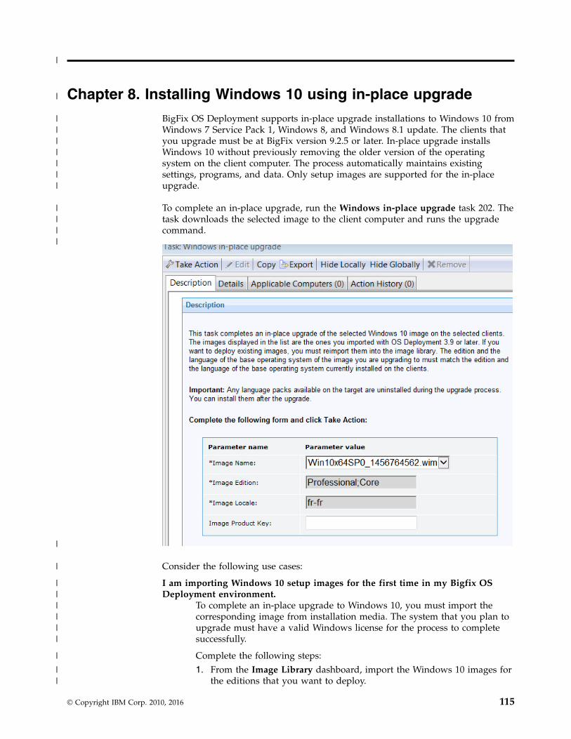
Chapter 8. Installing Windows 10 using in-place upgrade
BigFix OS Deployment supports in-place upgrade installations to Windows 10 fromWindows 7 Service Pack 1, Windows 8, and Windows 8.1 update. The clients thatyou upgrade must be at BigFix version 9.2.5 or later. In-place upgrade installsWindows 10 without previously removing the older version of the operatingsystem on the client computer. The process automatically maintains existingsettings, programs, and data. Only setup images are supported for the in-placeupgrade.
To complete an in-place upgrade, run the Windows in-place upgrade task 202. Thetask downloads the selected image to the client computer and runs the upgradecommand.
Consider the following use cases:
I am importing Windows 10 setup images for the first time in my Bigfix OSDeployment environment.
To complete an in-place upgrade to Windows 10, you must import thecorresponding image from installation media. The system that you plan toupgrade must have a valid Windows license for the process to completesuccessfully.
Complete the following steps:1. From the Image Library dashboard, import the Windows 10 images for
the editions that you want to deploy.
© Copyright IBM Corp. 2010, 2016 115
|
|
|||||||
||||
|
|
||||||
|
||

2. Run Task 202 selecting the image you want to deploy. Specify theimage product key if needed.
You do not need to create a new MDT Bundle for Windows in-placeupgrades. If you want to complete bare metal and reimaging deploymentsof Windows 10, you must create an MDT Bundle with the required tools.For more information, see Chapter 3, “Managing MDT Bundles andDeployment Media for Windows targets,” on page 37.
I already have one or more Windows 10 setup images in my BigFix OSDeployment environment.
If you already have Windows 10 setup images in the Image Library,complete the following steps:1. If you plan to use Windows 10 setup images that you had already
imported with OS Deployment Version 3.8, you must import themagain to enable them for the in-place upgrade..
2. Run Task 202 selecting the image you want to deploy. Specify theimage product key if needed.
Important:
The base system language that is currently installed on the client system is the onethat will be upgraded. If additional language locales were installed on the client,these are uninstalled during the upgrade.
Requirements and Limitations
The following requirements and limitations apply:v The client source operating system must be of the same architecture as the
Windows 10 image you are installing (x86 or x64).v In-place upgrade of targets with encrypted disks is not supported.v You cannot deploy an image of a base language different from base language of
the client to be upgraded.v The operating system editions must be compatible for the upgrade. The upgrade
process checks the edition that is currently installed on the client and upgradesit, if the image that you are deploying contains an edition that is compatible forthe upgrade.
v You cannot capture (sysprep) a computer that was upgraded with an in-placeinstallation.
v The upgrade process disables the built-in Administrator account on the client.v You must disable any firewall or antivirus program on the target before the
deployment.
116 IBM BigFix: OS Deployment V3.9 User's Guide
||
|||||
||||
|||
||
|
|||
|
|
||
|
||
||||
||
|
||
|

Chapter 9. Bare Metal deployments
You can install and manage Tivoli Provisioning Manager for OS Deployment PXEservers and create profiles for bare metal deployments.
Bare Metal deployments are installations of operating systems to targets that eitherhave no operating system installed, or must be re-installed without preserving anyexisting data or settings.
A Bare Metal deployment normally requires the use of a PXE server. The targetsthat PXE boot to these servers see a menu with profiles available for deployment.For this purpose, Tivoli Provisioning Manager for OS Deployment must beinstalled on relays in your Endpoint Management environment. The installers canbe uploaded to the Bare Metal Server Management dashboard. You must installthe latest version available. After the install process completes, you are ready tocreate the profiles used for bare metal deployments.
You can create bare metal profiles from the Image Library dashboard. Theseprofiles are then sent and stored on the Bare Metal OS Deployment PXE server.After you upload the profiles, they are ready to be deployed to targets. Anycomputer that PXE boots and connects to a managed OS Deployment PXE servercan select the profile from the binding menu. That profile is deployed,downloading necessary files through the BigFix infrastructure.
You can also deploy bare metal profiles to Windows targets that do not have aconnection to a PXE Server by creating a network boot CD, DVD, or USB drive.These targets can boot and connect to the server directly through the boot media.For more information, see “Creating Windows Deployment Media” on page 43.
Bare Metal Deployment behavior on VMware targets
You can complete bare metal deployments of VMware ESXi Version 5 and later onBIOS targets. Unlike Windows and Linux targets, when the bare metal deploymentcompletes successfully, VMware targets are automatically powered off. You mustpower them on manually. The BigFix Client is not installed during the deployment.
Creating bare metal profilesCreate Bare Metal profiles from the Image Library dashboard, which you can thenupload to the server.
To deploy images to Windows, Linux and VMware Bare Metal targets, you createbare metal profiles from the Image Library. You then upload the profiles to theServer so that they can be deployed on the selected targets.
Select an image for which to create a bare metal profile and click Create BareMetal Profile.
© Copyright IBM Corp. 2010, 2016 117

A wizard with the information retrieved from the image is displayed. Dependingon whether the type of image you select is a Linux or VMware image (.LIM) , or aWindows image (.WIM), the fields you are required to specify differ.
Creating Bare Metal Profiles for Windows ImagesCreate Bare Metal profiles from the Image Library dashboard to perform baremetal deployments on Windows targets.
Select a Windows image and click Create Bare Metal Profile.
A wizard with the information retrieved from the image is displayed. Dependingon whether the type of WIM image you select is captured or created frominstallation media (ISO), some of the required and optional fields are different.Values for some fields are already set but you can change them as appropriate.
If you have profiles that were created with earlier versions of OS Deployment,when you edit them, some fields might be preset to values that cannot be changedto ensure compatibility.
If your network supports multicast communication, and you want to deploy baremetal profiles using multicast, you can specify multicast parameters in theMulticast tab.
You can specify network configuration parameters for the targets receiving theprofile by using the Network tab. The default network configuration is DHCP. Ifyour targets have multiple interface cards (NICs) use the Change Bare MetalTarget Network Configuration task (354) to configure them.
Note: If you specify a value enclosed by {} (curly brackets) for a field in thewizard or for a parameter value in the Manual tab, the enclosed value isconsidered as a relevance that will be evaluated. You must ensure that the syntax
118 IBM BigFix: OS Deployment V3.9 User's Guide
||||

of the values enclosed by the curly brackets is correct. If you want to use the curlybracket as part of the field value without a relevance substitution, you mustspecify it with a double curly bracket at the beginning, for example:{{yes}
Common bare metal profile fields (both ISO and captured images)
Required fields:
Display NameThe name of the bare metal profile created from the image that youselected. By default, the name is derived from the image name andthe type of profile (in this case Bare Metal). You can specify amaximum of 70 alphanumeric characters.
Registered OwnerSpecify the name of the person registered to use the operatingsystem
Registered OrganizationSpecify the full name of the organization to which the registeredowner belongs.
Image LocaleChoose the image locale for the operating system if different fromthe preset one.
Image Keyboard LocaleThe keyboard locale is automatically set to match the image locale.
Time ZoneSelect the time zone of the target operating system
Hostname RuleSpecify the hostname rule that will be used to build the hostname,computer name, and full computer name of the target. You canspecify values in the following forms:v A prefix.v A prefix and one or more variables.v One or more variables.
There is a limit of 8 alphanumeric characters if you specify a prefixonly. If you specify an asterisk (*) as prefix, the target hostname isset to a string formed by the characters IBMIBM- followed by astring assigned by Windows. Variables must be specified in theform [variable] enclosed by square brackets. You can concatenatevariables. Allowed variables are:v [IP] - IP Address of the primary interface that has performed a
PXE bootv [MAC] - Hardware Address of the primary interface that has
performed PXE boot)v [UUID] - System UUID as found in DMI (SMBIOS)v [SN] - Serial number as found in DMI (SMBIOS)v [AT] - Asset TAG as found in DMI (SMBIOS)v [BBSN] - Base Board Serial Number as found in DMI (SMBIOS)
Every variable keyword supports a range extension, and you candecide to include only part of the information. The range starts atvalue zero. The value [IP3] corresponds to the last byte of the IP
Chapter 9. Bare Metal deployments 119
||||
|
|
|
||||||
||
||
|
|
|
|
|||

address. In IP addresses bytes are separated by dots. For example,if you specify a hostname rule of pc-[IP3] and the IP address ofthe target is 192.168.0.232, the hostname becomes pc-232. If youspecify [IP0-2], the first three bytes of the IP address are included.For SN, UUID, AT, and BBSN values, the range corresponds to asubstring. You can also add R at the end of the range to start itfrom the last character specified. Dots are always removed fromthe IP address in the final string.
Note: If the deployment is started from network boot media, theIP address used in the hostname rule is the one assigned duringthe network boot.
MDT BundleThe MDT Bundle to be used for the deployment of the bare metalprofile. The MDT Bundle is preset based on the operating systemthat you want to deploy.
Deployment Final ActionSelect a final action to complete on the target at the end of thedeployment.
RestartThe target computer is restarted. This is the default actionfor all new profiles.
ShutdownThe target computer is shut down.
Log offThe target computer is logged off.
No actionThe current user stays logged in. This is the default actionfor all profiles that were created with OS Deploymentversions earlier than 3.8.
Note: If you are joining the target computer to a domain, only“Restart ” or “ Shutdown” are allowed. If you are editing a profilecreated with earlier versions of OS deployment and you select anMDT Bundle Version 3.8 or later, the default action is forced to“Restart ”.
Administrator PasswordSpecify the password of the Administrator account on the targetsystem. You are asked to enter the password twice forconfirmation. This field is mandatory only for images created frominstallation media (ISO). It is optional for captured images.
Assign relaysSelect this option to disable automatic relay selection on the targetsystem, and to set the Bare Metal server to which the targetconnects as Primary Relay, and the IBM BigFix server as SecondaryRelay. The following client settings for the target are updated atdeployment time:v __RelaySelect_Automatic = 0, to disable automatic relay
selectionv __RelayServer1, which is set to the relay with the Bare Metal
Server to which the target connects
120 IBM BigFix: OS Deployment V3.9 User's Guide
||||||||
|||

v __RelayServer2, which is set to the IBM BigFix server
To use this option, the MDT Bundle must be version 3.7 or later.
Required Domain Credentials
Specify the required Domain Credentials. For a description of thepossible values, see “Domain Credentials” on page 100.
Optional fields:
Product KeySpecify a valid Windows Product Key.
Client SettingsUse this field to set named variables that are assigned to thedeployed computer. The values you assign can be used either aslabels to identify computers with specific roles or as filters in Fixletactions and in Fixlet relevance to exclude an action on a target. Youmust specify the variables in a NAME:VALUE format. If you specifymultiple variables, each one must be separated by a vertical bar“|”. After a deployment, you can display these values in the IBMBigFix console by selecting the specified computer, and clicking“Edit Computer Settings”. The settings are listed under “CustomSettings.”
Examples of how to use client settings to configure the target aftera deployment are available on the Endpoint Manager wiki at thislink: https://www.ibm.com/developerworks/community/wikis/home?lang=en#!/wiki/Tivoli%20Endpoint%20Manager/page/Using%20the%20Client%20Settings%20field%20to%20configure%20targets%20during%20deployments.
A complete list of available client configuration settings, and adescription of how to use them is available on the BigFix wiki atthis link: https://www.ibm.com/developerworks/community/wikis/home?lang=en#!/wiki/Tivoli%20Endpoint%20Manager/page/Configuration%20Settings?section=Clients/library/cc749015%28v=ws.10%29.aspx
Prompt end user for properties You can optionally select this option to prompt the user at thetarget computer for a hostname and network parameters. Whenthe deployment starts on the target, a user interface is displayedand the user can configure the hostname and network settings forone or more network interfaces (NICs) available on the targetsystem. This option is useful to view and check the networkparameters that will be applied to the target at deployment time,and to change them if needed. For more information about theproperties you can specify, see “Specifying target networkparameters at deployment time” on page 129.
Deployment PasswordProviding a deployment password protects the profile duringdeployment. Protected profiles are installed only after you providethe correct password at the target when prompted
Auto Deploy TimeoutIf you specify a value in seconds, a counter is started during thePXE boot on the target machine, and when the specified timeexpires, the profile is automatically installed on the target.
Chapter 9. Bare Metal deployments 121
|||||||||||

Image Setup Timeout If you specify a timeout value in seconds, the setup of the WIMimage is interrupted when the specified time expires. This option isavailable only for Tivoli Provisioning Manager for OS DeploymentServers version 7.1.1.14 or later.
Repartition the disksThis check box is selected by default. Clear it to avoidre-partitioning the disks on the target machine. In this case, onlythe specified partitions are deployed on the existing partitionlayout.
Disable enhanced error detectionSelect this option to prevent modifications to the boot sequenceduring the bare metal deployment. For more information, see“Enhanced error detection” on page 96.
Unique fields for creating a Bare Metal profile for an ISO image:
Required fields:
EditionThe operating system edition you are deploying. Expand the list toselect a different edition.
Client Version The displayed version depends on the MDT Bundle that is used.For MDT Bundles earlier than version 3.7, the best match isdisplayed. For MDT Bundle versions 3.7 or later, all client versionsare supported. To select a Client version your Bare Metal OSDeployment server must be at version 7.1.1.18 or later.
122 IBM BigFix: OS Deployment V3.9 User's Guide

Unique fields for creating a Bare Metal Profile for a captured image:
Enable AdministratorYou can choose to enable the Administrator account on the targetsystem. If you select this option, you must also specify thepassword.
Administrator passwordSpecify the password of the Administrator on the target system.You are asked to enter the password twice to confirm.
When you create bare metal profiles, you can specify the partition layout. ThePartition Mappings section is the same as in “Mapping partitions” on page 96 butthe behavior is different in bare metal deployments. When you add partitions, thesize of the partitions can be specified using percentages. If you did not select tore-partition the disks, you must adapt the partitions of the source image to matchthe physical partitions of the target.
Note: You cannot edit boot partitions because the size of these partitions is fixed.
If you decide to repartition the disks on the target machine, the disks are formattedand the partitions are recreated on the target machine as you mapped them in theWIM. If you do not repartition the disks on the target machine, the same rules thatare described for the number of partitions for reimaging apply.
Chapter 9. Bare Metal deployments 123

If the number of partitions you send to the target is less than the number ofpartitions that exist on the target, the results of the validation depend on how youmapped the partitions. For example, a target has Windows 7 with a bootablepartition and a system partition. If you deploy a Windows 7 customized bare metalprofile with only the system partition and you map this partition to the firstpartition of the target, the deployment fails. If you map the partition in yourprofile to the second partition of the target, the deployment is successful.
If you are deploying a bare metal profile on a UEFI target, a dedicated bootpartition (ESP) is always created on the target, regardless of how these partitionswere mapped in the WIM (system and boot partitions are mapped on the sametarget partition in the partition editor.)
Use the Manual tab to manually specify customization options in theCustomSettings.ini file.
The following settings are not present in the Manual tab because they are handledseparately by encryption: AdminPassword, DomainAdmin, JoinDomain,
124 IBM BigFix: OS Deployment V3.9 User's Guide

DomainAdminDomain, DomainAdminPassword, and MachineObjectOU. The settings in theWizard tab take precedence over the settings that are found in Manual tab forthese values.
Note: Making modifications in this tab can have unexpected effects if notappropriately tested and verified.
Requirements and limitations
If you are deploying bare metal profiles for XP images, the following limitationsapply:v Only captured images are supported.v The Administrator password field must be set to blank on the source machine
before you capture. You can optionally specify a password for the Administratorduring profile creation.
v If a sysprep.inf file exists on the target, it must be deleted before you deploythe profile.
v XP Mass storage devices must have been manually injected in the MDT Bundleduring the bundle creation process. See “Preparing drivers for Windowsdeployments” on page 61.
To deploy Windows 10 bare metal profiles, you must have MDT Bundle version 3.8or later created with WADK 10 and MDT 2013 Update 1. The Bare Metal OSDeployment Server must be version 7.1.1.19 or later.
Deploying bare metal profiles in multicast
If you want to deploy a Bare Metal profile using multicast, you must specify thecorresponding parameters in the Multicast tab:
Chapter 9. Bare Metal deployments 125

To enable multicast for the profile, select the corresponding option. Default valuesfor multicast deployment are provided. You can accept or change them, dependingon the characteristics of your network:
Multicast ModeDefines how the multicast distribution is managed on the targets atdeployment time for the profile:
Probe and FailIf the probe on the target fails, the deployment task also fails.
Probe and Fall back to UnicastIf the probe on the target fails, deployment of the profile occurs inunicast
Force Deployment on the target is forced to multicast regardless of proberesults.
Group SetupSelect the type of multicast group that is used for the deployment. You canaccept or change the associated parameters.
126 IBM BigFix: OS Deployment V3.9 User's Guide

Closed GroupTargets join the group as they are ready. When the followingcriteria are satisfied, the group is closed and distribution begins.This is the default.
Number of targets in groupSpecify the maximum number of targets allowed in thegroup. The default value is 12.
Wait for targets up to minutesSpecify the maximum number of minutes to wait fortargets before starting the multicast deployment. Thedefault value is 10 minutes.
Minimum number of targets in groupSpecify the minimum number of targets that must join fora multicast deployment. If the specified value is notreached, deployment is completed in unicast. The defaultvalue is 2.
Open GroupTargets can join the group as they are ready, at any time duringdeployment. You can change the associated parameter.
Average number of targets in groupSpecify the average number of targets expected in thegroup. This value is used to optimize blocksynchronization. The closer the number of actual targets isto this value, the more efficient the multicast deployment.The default value is 16.
Advanced ParametersMulticast advanced customization and tuning options that apply to bothmulticast group types.
Block synchronization wait time in secondsSpecify how many seconds the server must wait before sending thenext block. This value is preset to 120 seconds. If you specify avalue less than 5 seconds, the block synchronization wait time isforced to 5.
Block size in MBThe image is divided into blocks that are sent to the targets. Thisparameter sets the maximum size of the data blocks (in megabytes)sent in each transmission packet. The default value is 16Megabytes.
Enable block encryptionSpecify if the blocks must be encrypted during transmission.
Note: If you have enabled multicast on one or more bare metal profiles and youhave sent them to OS Deployment Servers that are at version 7.1.1.18 or earlier,when you upgrade the servers to OS Deployment version 7.1.1.19, these profilesbecome out of sync. You must initiate a synchronize action on the upgraded OSDeployment Servers. The action automatically pre-caches the profiles.
Chapter 9. Bare Metal deployments 127
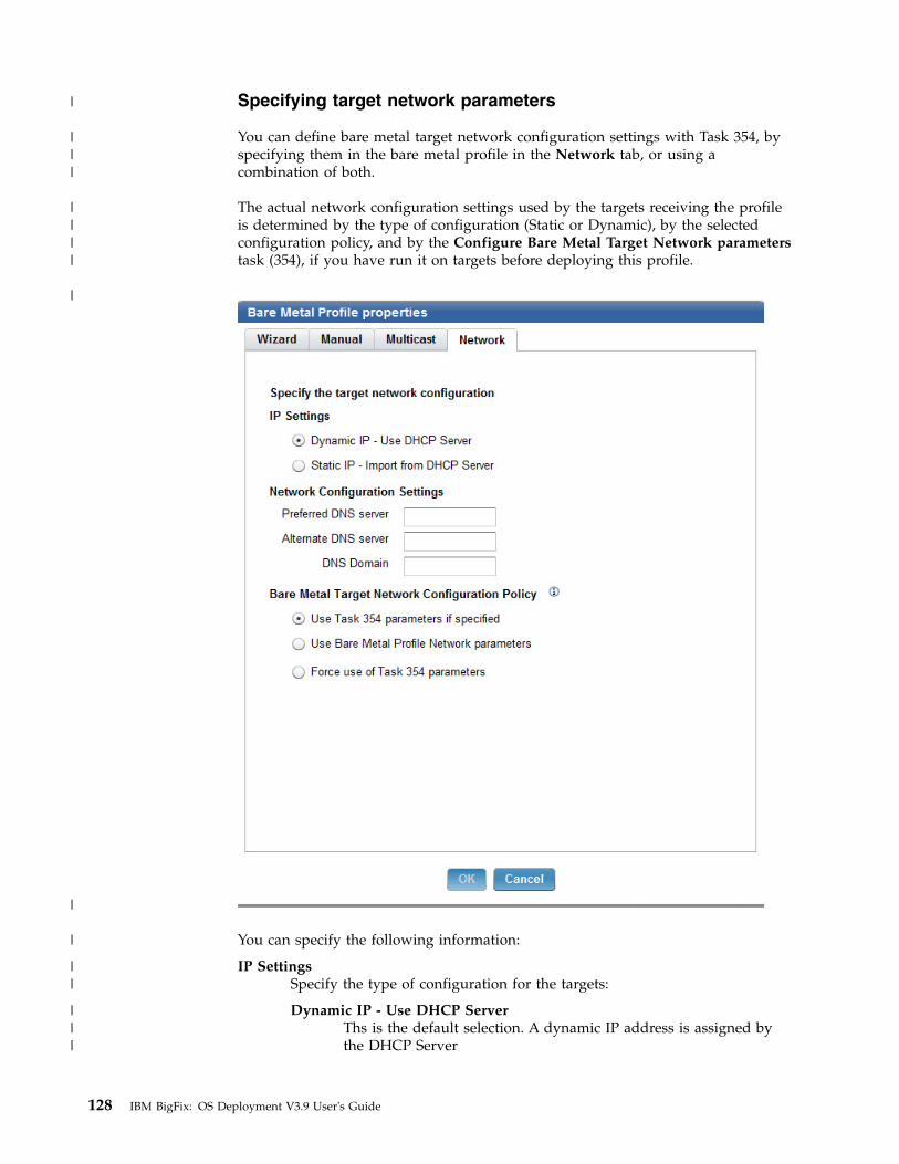
Specifying target network parameters
You can define bare metal target network configuration settings with Task 354, byspecifying them in the bare metal profile in the Network tab, or using acombination of both.
The actual network configuration settings used by the targets receiving the profileis determined by the type of configuration (Static or Dynamic), by the selectedconfiguration policy, and by the Configure Bare Metal Target Network parameterstask (354), if you have run it on targets before deploying this profile.
You can specify the following information:
IP SettingsSpecify the type of configuration for the targets:
Dynamic IP - Use DHCP ServerThs is the default selection. A dynamic IP address is assigned bythe DHCP Server
128 IBM BigFix: OS Deployment V3.9 User's Guide
|
|||
||||
|
|
|
||
|||

Static IP - Import from DHCP ServerIP address, gateway, and network mask are imported from theDHCP Server
Network Configuration SettingsOptional. These parameters are used only if you select a static IPconfiguration. If your policy is to use the bare metal target configurationparameters previously defined with task 354, the parameters that were notalready set with the task and specified in this section are considered. Ifthere are parameters in common, the ones specified in the task takeprecedence. The parameters specified in this section are also used if youselect a static IP configuration and you select to ignore any parameterdefined with task 354. The configuration settings in this section aredisabled if you are configuring a dynamic IP and you have selected toignore any previously defined target network configuration using task 354).
Preferred DNS ServerSpecify the IP address of the Preferred DNS server in your network
Alternate DNS ServerSpecify the IP address of the Alternate DNS server in your network
DNS DomainSpecify The Domain Name Server name
Bare Metal Target Network Configuration PolicyChoose the configuration policy that must be applied to the selectedtargets for this profile.
Use Task 354 parameters if specified
If you have run the Change Bare Metal Target Networkconfiguration task 354 to configure network parameters on targetsof this profile, and you have selected this option, the parametersyou specified in the task will have precedence over the sameparameters specified in the profile. A field by field check isperformed, and the profile parameters that were not specified inthe task are also used.
Use Bare Metal Network Profile Parameters
Select this option if you want to ignore any previously definedtarget network parameters with task 354. Only the parametersspecified in the profile are used.
Force use of Task 354 parameters
Select this option if you want to use only network parametersdefined with Task 354. If you have not previously run task 354 onthe targets of this profile, the deployment fails.
To set or change bare metal target network configuration settings using thecorresponding task (ID 354), see “Changing Bare Metal Target NetworkConfiguration Settings” on page 154.
Specifying target network parameters at deployment time
If you have selected the Prompt end user for properties option in the bare metalprofile properties wizard, a user interface is displayed on the target system atdeployment time. From this interface you can view and change the network
Chapter 9. Bare Metal deployments 129
|||
|||||||||||
||
||
||
|||
|
|||||||
|
|||
|
|||
|||
interface settings, the hostname, and the partition mapping information that willbe applied to the target. You can accept the displayed settings or change them asneeded:
Network interface card (NIC) All settings defined with task 354 or specified in the Network tab of thebare metal profile properties wizard are displayed. If the target has morethan one network interface card (NIC), a separate configuration window isdisplayed for each one. Each interface is identified by the correspondingMAC address.
HostnameDisplays the hostname previously set with task 350 if used, or the finalhostname value resulting from the application of the hostname rule youspecified in the bare metal profile.
Note: If you set the hostname for a target at deployment time, this valueis maintained for any subsequent bare metal deployments, independentlyof the hostname rule specified in the bare metal profile. To change thehostname, you can either use task 350 or deploy a new profile selecting the"Prompt end user for properties" option.
Partition mappingDisplays the partition mapping information that was specified using task350. You can resize the partitions or accept the current mapping. If thisinformation is not available, the related page is not displayed at the target.
Creating Bare Metal Profiles for Linux ImagesCreate Bare Metal profiles from the Image Library dashboard, to perform baremetal deployments on Linux targets.
Select a Linux image (.LIM) and click Create Bare Metal Profile.
A wizard with the information retrieved from the selected Linux image isdisplayed. Some field values are already set but you can change them asappropriate. Depending on whether the selected image is captured or created frominstallation media, not all fields apply.
You can deploy your bare metal profiles in multicast, if your network supports it,by specifying the required parameters in the Multicast tab.
The default network configuration for targets is DHCP. You can specify differentnetwork configuration parameters for the targets receiving the profile by using theNetwork tab. If your targets have multiple network interface cards, use theChange Bare Metal Target Network Configuration task (354) to configure them.
Note: If you specify a value enclosed by {} (curly brackets) for a field in thewizard or for a parameter value in the Manual tab, the enclosed value isconsidered as a relevance that will be evaluated. You must ensure that the syntaxof the values enclosed by the curly brackets is correct. If you want to use the curlybracket as part of the field value without a relevance substitution, you mustspecify it with a double curly bracket at the beginning, for example:{{yes}
Common bare metal profile fields (both setup and captured images)
Required fields:
130 IBM BigFix: OS Deployment V3.9 User's Guide
||||

Display nameThe name of the bare metal profile created from the image that youselected. by default it is the same name as the image.
Image LocaleChoose the image locale for the operating system if different formthe preset one.
Time ZoneSelect the time zone of the target operating system
Hostname RuleSpecify the hostname rule that will be used to build the hostname,computer name, and full computer name of the target. You canspecify values in the following forms:v A prefix.v A prefix and one or more variables.v One or more variables.
There is a limit of 8 alphanumeric characters if you specify a prefixonly. If you specify an asterisk (*) as prefix, the target hostname isset to a string formed by the characters IBMIBM- followed by astring assigned by the operating system. Variables must bespecified in the form [variable] enclosed by square brackets. Youcan concatenate variables. Allowed variables are:v [IP] - IP Address of the primary interface that has completed a
PXE bootv [MAC] - Hardware Address of the primary interface that has
completed the PXE boot)v [UUID] - System UUID as found in DMI (SMBIOS)v [SN] - Serial number as found in DMI (SMBIOS)v [AT] - Asset TAG as found in DMI (SMBIOS)v [BBSN] - Base Board Serial Number as found in DMI (SMBIOS)
Every variable keyword supports a range extension, and you candecide to include only part of the information. The range starts atvalue zero. The value [IP3] corresponds to the last byte of the IPaddress. In IP addresses bytes are separated by dots. For example,if you specify a hostname rule of pc-[IP3] and the IP address ofthe target is 192.168.0.232, the hostname becomes pc-232. If youspecify [IP0-2], the first three bytes of the IP address are included.For SN, UUID, AT, and BBSN values, the range corresponds to asubstring. You can also add R at the end of the range to start itfrom the last character specified. Dots are always removed fromthe IP address in the final string.
Note: If the deployment is started from network boot media, theIP address used in the hostname rule is the one assigned duringthe network boot.
Root PasswordSpecify the root password for the target system. You are asked tospecify it twice.
The following figure displays a bare metal profile for an image created frominstallation media (Setup).
Chapter 9. Bare Metal deployments 131
||||
|
|
|
||||||
||
||
|
|
|
|
|||||||||||
|||

Optional fields
Prompt end user for properties Select this option to prompt the user at the target computer for a hostnameand network parameters. When the deployment starts on the target, a userinterface is displayed and the user can configure the hostname andnetwork settings for one or more network interfaces (NICs) available onthe target system. For more information about the properties displayed atthe target, see “Specifying target network parameters at deployment time”on page 156, and “Changing Bare Metal Target Network ConfigurationSettings” on page 154.
Installer Kernel parametersSpecify one or more optional kernel parameters for the Linux installer, andthe corresponding values if required.
Kernel parametersSpecify one or more optional kernel parameters for the installed Linuxoperating system.
Kernel parameters have the following syntax:#<model>#<parameter>#
Where the model refers to the computer model of the target to which theparameter is applied, and the parameter can be a single keyword or in theform key=value. Each model/parameter pair must be separated by a blank
132 IBM BigFix: OS Deployment V3.9 User's Guide
|||||||||

character. You can use the asterisk as a wildcard character. For example,#vm*#<parameter># applies the specified parameter to all models withnames beginning with “vm”. The model field is not case-sensitive.
You can also replace existing values for parameters. For example, if youwant to set a lower screen resolution on all VMware virtual machineswhile defining a higher screen resolution for all other available models,write the following:#vm*#video=800x600-24#video=1024x800-32#
Client SettingsUse this field to set named variables that are assigned to the deployedcomputer. The values you assign can be used either as labels to identifycomputers with specific roles or as filters in Fixlet actions and in Fixletrelevance to exclude an action on a target. You must specify the variablesin a NAME:VALUE format. If you specify multiple variables, each one must beseparated by a vertical bar “|”. After a deployment, you can display thesevalues in the IBM BigFix console by selecting the specified computer, andclicking “Edit Computer Settings”. The settings are listed under “CustomSettings.”
Examples of how to use client settings to configure the target after adeployment are available on the Endpoint Manager wiki at this link:https://www.ibm.com/developerworks/community/wikis/home?lang=en#!/wiki/Tivoli%20Endpoint%20Manager/page/Using%20the%20Client%20Settings%20field%20to%20configure%20targets%20during%20deployments.
A complete list of available client configuration settings, and a descriptionof how to use them is available on the BigFix wiki at this link:https://www.ibm.com/developerworks/community/wikis/home?lang=en#!/wiki/Tivoli%20Endpoint%20Manager/page/Configuration%20Settings?section=Clients/library/cc749015%28v=ws.10%29.aspx
Deployment passwordProviding a deployment password protects the profile during deployment.Protected profiles are installed only after you provide the correct passwordat the target when prompted.
Auto Deploy Timeout (sec)If you specify a value in seconds, a counter is started during the PXE booton the target machine. When the specified time expires, the profile isautomatically installed on the target.
Unique fields for images created from installation media (setup)
Required fields
Client VersionSpecify the version of the BigFix client to be installed on the target.The default selection is the same version as the BigFix server.
Optional fields
Allow client trafficThis option is selected by default. It is needed if the selected target has theoperating system firewall enabled, to allow inbound udp traffic from theServer. You can also allow inbound traffic on the target by running fixlets678 or 682. For more information, see “Changing Firewall settings” on page112.
Chapter 9. Bare Metal deployments 133
||||||||||
||||||
||||||

Unique fields for captured images
Required fields
Linux OS Resource The OS Resource to be used for the deployment of the selectedimage. This field displays the OS resource that best matches theselected image.
Using the Partition Editor
Depending on the type of image, different partitioning actions are available. Towork with partitions, expand the Partition Editor section of the wizard tab. If youselected a captured image, the partition editor displays the partition layout of thecaptured reference machine. You cannot add new partitions to captured images,but you can edit primary partitions and logical volumes to change their sizes, ordelete partitions. You can complete the following actions:v Resize selected primary partitions and logical volumes. Highlight the partition
and click the edit icon to change the size.
You can specify the size in kilobytes, megabytes, gigabytes, terabytes andpercentages. If more than one partition is defined, specifying a value of onehundred percent (100%) for a partition, means that it will occupy all remainingspace after the specified sizes have been allocated to the other partitions.
v Delete an existing partition. Select the partition to delete and click thecorresponding option.
If you are deploying images imported from installation media ( setup) you do nothave to edit partitions. In this case, the default partitioning is applied. If you want
134 IBM BigFix: OS Deployment V3.9 User's Guide
|
|
||||
|
||||||
|||
|||||
|||
|
||

to edit partitions, you can specify a partition layout by expanding the PartitionEditor section of the wizard tab. Consider the following partitioning use cases,depending on the characteristics of your target systems:
I want to define multiple partitions on a single physical disk:
1. Define the partitions on the disk by clicking the corresponding option:
You can add partitions or logical volumes. Specify the requiredinformation.
2. If you want to add a logical volume, select LVM from the File systemlist, and specify a Volume Group name. When you click OK the Logicalvolume Editor becomes available at the bottom of the section. ClickAdd Logical volume and specify the characteristics of the logicalvolume.
Chapter 9. Bare Metal deployments 135
|||
|
||
|
|
|||
||||||
|

I want to define multiple partitions on different physical disks
1. Define the physical disks on the machine that receives the profile .Click Define Disks The default disk name is /dev/sda. To define morephysical disks, specify each disk element separated by a semicolon. Forexample: /dev/sda;/dev/sdb. Click OK to save your changes.
2. Click Add Partition and select a disk that you defined in the previousstep to partition it.
Specify the size of the partition, mount point and file system type. Youcan set the disk as primary. Specify the partition mount point. To add alogical volume, select LVM from the File System List, and specify aLogical Volume Group name. When you click OK the Logical volumeEditor becomes available at the bottom of the section. Click AddLogical volume and specify the characteristics of the logical volume.
3. Repeat step 2 for each physical disk that you defined.
Important:
v You can define up to three primary partitions, by selecting the appropriateoption. If you want to deploy the profile in multicast to BIOS targets, you candefine a maximum of two primary partitions.
v If you are deploying a Linux Setup image in multicast on a target that hasexisting Windows partitions not on the primary disk, these partitions will not beformatted. This must be considered when defining multiple disks using thepartition editor in the profile.
v When you define multiple partitions for a disk, make sure you specify the sizeof at least one of the partitions using percentage (%) not with a fixed value, soas to optimize disk allocation and avoid disk space errors. This best practiceapplies to Logical Volumes too. When you define a fixed size for a VolumeGroup, for example 10 gigabytes, the actual size available to create LogicalVolumes is slightly less (usually in the order of a few megabytes). To avoidspace allocation problems, when you define volume groups you should specifythe size of at least one Logical Volume in percentage (%).
v When you edit a profile containing a partition layout, if you change the diskmapping, the current layout is erased. A warning message is issued asking youto confirm or to cancel the operation.
.
136 IBM BigFix: OS Deployment V3.9 User's Guide
|
||||
|||
|||||||
|
|
|||
||||
||||||||
|||
|

Manual tab settings
Using the Manual tab, you can customize the installation of Linux imagesimported from installation media (Setup) with specific settings that are notavailable in the wizard. Uncomment the settings you want to customize andinclude in your deployment. For more information about the customization of theconfiguration files, see “Linux configuration options” on page 107 or refer to thespecific Linux vendor documentation.
Deploying bare metal profiles in multicast
To deploy bare metal profiles using multicast, specify the parameters in theMulticast tab. Multicast deployments are supported for Linux captured images onboth BIOS and UEFI targets. Multicast deployments of Linux images importedfrom installation media (Setup) are limited to Linux RedHat version 6 and 7images on BIOS targets only. If you are deploying a RedHat image on a BIOStarget, the number of primary partitions you can define for the target is limited totwo.
Chapter 9. Bare Metal deployments 137

Important: When deploying setup images in multicast, if you define multiplepartitions for the first disk (/dev/sda), you must leave at least 5 gigabytes of freespace that is needed locally to store the image file, or, alternatively, specify the sizeof at least one of the partitions in percentage (%) .
To enable multicast for the profile, select the corresponding option. Default valuesfor multicast deployment are provided. You can accept or change them, dependingon the characteristics of your network:
Multicast ModeDefines how the multicast distribution is managed on the targets atdeployment time for the profile:
Probe and FailIf the probe on the target fails, the deployment task also fails.
Probe and Fall back to UnicastIf the probe on the target fails, deployment of the profile occurs inunicast
Force Deployment on the target is forced to multicast regardless of proberesults.
138 IBM BigFix: OS Deployment V3.9 User's Guide

Group SetupSelect the type of multicast group that is used for the deployment. You canaccept or change the associated parameters.
Closed GroupTargets join the group as they are ready. When the followingcriteria are satisfied, the group is closed and distribution begins.This is the default.
Number of targets in groupSpecify the maximum number of targets allowed in thegroup. The default value is 12.
Wait for targets up to minutesSpecify the maximum number of minutes to wait fortargets before starting the multicast deployment. Thedefault value is 10 minutes.
Minimum number of targets in groupSpecify the minimum number of targets that must join fora multicast deployment. If the specified value is notreached, deployment is completed in unicast. The defaultvalue is 2.
Open GroupTargets can join the group as they are ready, at any time duringdeployment. You can change the associated parameter.
Average number of targets in groupSpecify the average number of targets expected in thegroup. This value is used to optimize blocksynchronization. The closer the number of actual targets isto this value, the more efficient the multicast deployment.The default value is 16.
Advanced ParametersMulticast advanced customization and tuning options that apply to bothmulticast group types.
Block synchronization wait time in secondsSpecify how many seconds the server must wait before sending thenext block. This value is preset to 120 seconds. If you specify avalue less than 5 seconds, the block synchronization wait time isforced to 5.
Block size in MBThe image is divided into blocks that are sent to the targets. Thisparameter sets the maximum size of the data blocks (in megabytes)sent in each transmission packet. The default value is 16Megabytes.
Enable block encryptionSpecify if the blocks must be encrypted during transmission.
Specifying target network parameters
You can define bare metal target network configuration settings with Task 354, byspecifying them in the bare metal profile in the Network tab, or using acombination of both.
Chapter 9. Bare Metal deployments 139
|
|||

The actual network configuration settings used by the targets receiving the profileis determined by the type of configuration (Static or Dynamic), by the selectedconfiguration policy, and by the Configure Bare Metal Target Network parameterstask (354), if you have run it on targets before deploying this profile.
You can specify the following information:
IP SettingsSpecify the type of configuration for the targets:
Dynamic IP - Use DHCP ServerThs is the default selection. A dynamic IP address is assigned bythe DHCP Server
Static IP - Import from DHCP ServerIP address, gateway, and network mask are imported from theDHCP Server
Network Configuration SettingsOptional. These parameters are used only if you select a static IPconfiguration. If your policy is to use the bare metal target configurationparameters previously defined with task 354, the parameters that were not
140 IBM BigFix: OS Deployment V3.9 User's Guide
||||
|
|
|
||
|||
|||
||||

already set with the task and specified in this section are considered. Ifthere are parameters in common, the ones specified in the task takeprecedence. The parameters specified in this section are also used if youselect a static IP configuration and you select to ignore any parameterdefined with task 354. The configuration settings in this section aredisabled if you are configuring a dynamic IP and you have selected toignore any previously defined target network configuration using task 354).
Preferred DNS ServerSpecify the IP address of the Preferred DNS server in your network
Alternate DNS ServerSpecify the IP address of the Alternate DNS server in your network
DNS DomainSpecify The Domain Name Server name
Domain Search orderSpecify the domain search order. Each domain name must beseparated by blanks.
Bare Metal Target Network Configuration PolicyChoose the configuration policy that must be applied to the selectedtargets for this profile.
Use Task 354 parameters if specified
If you have run the Change Bare Metal Target Networkconfiguration task 354 to configure network parameters on targetsof this profile, and you have selected this option, the parametersyou specified in the task will have precedence over the sameparameters specified in the profile. A field by field check isperformed, and the profile parameters that were not specified inthe task are also used.
Use Bare Metal Network Profile Parameters
Select this option if you want to ignore any previously definedtarget network parameters with task 354. Only the parametersspecified in the profile are used.
Force use of Task 354 parameters
Select this option if you want to use only network parametersdefined with Task 354. If you have not previously run task 354 onthe targets of this profile, the deployment fails.
To set or change bare metal target network configuration settings using thecorresponding task (ID 354) , see “Changing Bare Metal Target NetworkConfiguration Settings” on page 154.
Specifying target network parameters at deployment time
If you have selected the Prompt end user for properties option in the bare metalprofile properties wizard, a user interface is displayed on the target system atdeployment time. From this interface you can view and change the networkinterface settings, the hostname, and the partition mapping information that willbe applied to the target. You can accept the displayed settings or change them asneeded:
Network interface card (NIC) All settings defined with task 354 or specified in the Network tab of the
Chapter 9. Bare Metal deployments 141
|||||||
||
||
||
|||
|||
|
|||||||
|
|||
|
|||
|||

bare metal profile properties wizard are displayed. If the target has morethan one network interface card (NIC), a separate configuration window isdisplayed for each one. Each interface is identified by the correspondingMAC address.
HostnameDisplays the hostname previously set with task 350 if used, or the finalhostname value resulting from the application of the hostname rule youspecified in the bare metal profile.
Note: If you set the hostname for a target at deployment time, this valueis maintained for any subsequent bare metal deployments, independentlyof the hostname rule specified in the bare metal profile. To change thehostname, you can either use task 350 or deploy a new profile selecting the"Prompt end user for properties" option.
Partition mappingDisplays the partition mapping information that was specified using task350. You can resize the partitions or accept the current mapping. If thisinformation is not available, the related page is not displayed at the target.
Creating Bare Metal Profiles for VMware ESXi ImagesYou can create and deploy VMWare ESXi Bare Metal profiles on targets.
Select a VMware image (.LIM) and click Create Bare Metal Profile.
A wizard with the information retrieved from the selected image displayed.
Required fields:
Display nameThe name of the bare metal profile created from the image that youselected. By default it is the same name as the image.
142 IBM BigFix: OS Deployment V3.9 User's Guide

Image Keyboard LocaleChoose the image keyboard locale for the operating system.
Hostname RuleSpecify the hostname rule that will be used to build the hostname,computer name, and full computer name of the target. You can specifyvalues in the following forms:v A prefix.v A prefix and one or more variables.v One or more variables.
There is a limit of 8 alphanumeric characters if you specify a prefix only. Ifyou specify an asterisk (*) as prefix, the target hostname is set to a stringformed by the characters IBMIBM- followed by a string assigned by theoperating system. Variables must be specified in the form [variable]enclosed by square brackets. You can concatenate variables. Allowedvariables are:v [IP] - IP Address of the primary interface that has performed a PXE bootv [MAC] - Hardware Address of the primary interface that has performed
PXE boot)v [UUID] - System UUID as found in DMI (SMBIOS)v [SN] - Serial number as found in DMI (SMBIOS)v [AT] - Asset TAG as found in DMI (SMBIOS)v [BBSN] - Base Board Serial Number as found in DMI (SMBIOS)
Every variable keyword supports a range extension, and you can decide toinclude only part of the information. The range starts at value zero. Thevalue [IP3] corresponds to the last byte of the IP address. In IP addressesbytes are separated by dots. For example, if you specify a hostname rule ofpc-[IP3] and the IP address of the target is 192.168.0.232, the hostnamebecomes pc-232. If you specify [IP0-2], the first three bytes of the IPaddress are included. For SN, UUID, AT, and BBSN values, the rangecorresponds to a substring. You can also add R at the end of the range tostart it from the last character specified. Dots are always removed from theIP address in the final string.
Root PasswordSpecify the root password for the target system. You are asked to specify ittwice for confirmation.
Optional fields:
Deployment passwordProviding a deployment password protects the profile during deployment.Protected profiles are installed only after you provide the correct passwordat the target when prompted.
Auto Deploy Timeout (sec)If you specify a value in seconds, a counter is started during the PXE booton the target machine, and when the specified time expires, the profile isautomatically installed on the target.
By using the Manual tab, you can customize the installation with specific settingsthat are not available in the wizard. Uncomment the settings you want tocustomize and include in your deployment.
Chapter 9. Bare Metal deployments 143
||||
|
|
|
||||||
|
||
|
|
|
|
||||||||||

Important:
v VMware ESXi is supported for deeployment on BIOS targets only.v Any network parameters previously set with task 354 on targets of a VMware
ESXi bare metal deployment are ignored.
Working with Bare Metal Profiles
After a profile is created, it is displayed in the Bare Metal Profiles table at thebottom of the dashboard. If you select an image, all bare metal profiles that arecreated from that image are displayed.
You can edit the profile also by using the
icon. After the changes aresaved, an action is automatically generated to update the profile on any serversthat have that profile. If there are any servers with the profile, but that are out ofsync with the profile available in the console, a warning is shown and you can use
this icon
to resynchronize.
You can send the profile to the server by clicking Send to Server.
144 IBM BigFix: OS Deployment V3.9 User's Guide
||

This generates an action for any valid bare metal servers.
Note:
Bare metal servers might be invalid because they are an old version or do not haveencryption enabled.
It is recommended that images are pre-cached to bare metal servers where profilesare created. This way large files are immediately available when first attempting todeploy a profile.
From the Bare Metal Profile table in the Image Library, you can see on whichservers the profile exists by clicking the Servers with Profile link.
You can delete a profile on the server by selecting it and then clicking Delete; theprofile is removed also from all servers. An image cannot be deleted if there areprofiles that are created from it.
Deploying a bare metal profile from the target binding menu
To deploy a bare metal profile on your target, you must reboot the target from thenetwork by pressing a hot key, for example, F1 or F12. For information aboutwhich hot key to use, see your computer manual. Before you run the reboot fromthe network, ensure that the DHCP server is configured.
Important:
v If you are deploying a bare metal profile on a UEFI target, you must place thehard disk before the EFI shell in the boot sequence, otherwise the deploymentdoes not complete successfully.
v On VMware targets, when the deployment completes, the target is powered off.See “Bare Metal Deployment behavior on VMware targets” on page 117.
During the target reboot, the following window is displayed to download andinstall a Windows operating system according to the information of the bare metalprofile that is created from the IBM BigFix Console:
Chapter 9. Bare Metal deployments 145
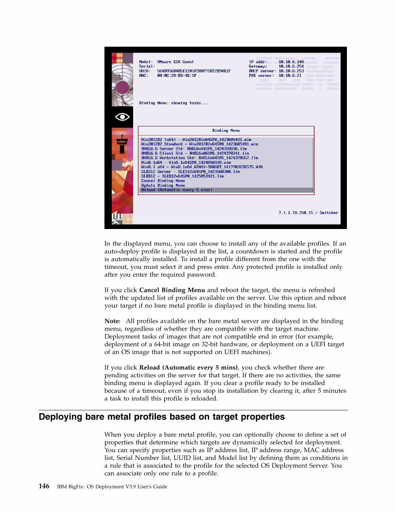
In the displayed menu, you can choose to install any of the available profiles. If anauto-deploy profile is displayed in the list, a countdown is started and the profileis automatically installed. To install a profile different from the one with thetimeout, you must select it and press enter. Any protected profile is installed onlyafter you enter the required password.
If you click Cancel Binding Menu and reboot the target, the menu is refreshedwith the updated list of profiles available on the server. Use this option and rebootyour target if no bare metal profile is displayed in the binding menu list.
Note: All profiles available on the bare metal server are displayed in the bindingmenu, regardless of whether they are compatible with the target machine.Deployment tasks of images that are not compatible end in error (for example,deployment of a 64-bit image on 32-bit hardware, or deployment on a UEFI targetof an OS image that is not supported on UEFI machines).
If you click Reload (Automatic every 5 mins), you check whether there arepending activities on the server for that target. If there are no activities, the samebinding menu is displayed again. If you clear a profile ready to be installedbecause of a timeout, even if you stop its installation by clearing it, after 5 minutesa task to install this profile is reloaded.
Deploying bare metal profiles based on target properties
When you deploy a bare metal profile, you can optionally choose to define a set ofproperties that determine which targets are dynamically selected for deployment.You can specify properties such as IP address list, IP address range, MAC addresslist, Serial Number list, UUID list, and Model list by defining them as conditions ina rule that is associated to the profile for the selected OS Deployment Server. Youcan associate only one rule to a profile.
146 IBM BigFix: OS Deployment V3.9 User's Guide

When you save the rule, it is uploaded on the deployment server. When targetsperform a PXE boot, the target properties are evaluated against the rule. If a matchis found, a deployment task is created for the target. If no match is found, thebinding menu is displayed. The target becomes eligible for deployment if at leastone of the conditions in the rule is true.You can also specify an expiry date for therule. After this date, the rule is no longer effective, and targets are not evaluatedagainst this rule.
For each profile, you can see if there are any associated rules and if the status ofthe rule is active or inactive.
To create a rule, complete the following steps from the Bare Metal Server Managerdashboard:
1. Select a bare metal profile and click
to create a rule for the profile. TheEdit Targeting Rule window is displayed.
Click Add to create a new condition in the rule.2. From the Property list, select the property that must be verified on the target.
Chapter 9. Bare Metal deployments 147

3. Specify a value for the target property.
Click OK to save the condition. To add other conditions, click Add, and selectanother property.
4. You can optionally specify an expiration date for the rule, different from thedefault date. When you select list target properties, such as MODEL LIST, you canuse the asterisk (*) as wildcard.
148 IBM BigFix: OS Deployment V3.9 User's Guide

You can also specify a question mark (?) as wildcard to represent a singlealphanumeric character.Possible values:
IP RangeThe IP address range for the targets. Specify the address rangeintervals, separating them with a hyphen (-).
IP List, MAC Address List, Serial Number List, UUID List, Model ListOne or more elements, separating each element with a comma.
For example, to specify a UUID list:564D9938F62C241D43324B5B24A68A0B,564D9938F62C241D43324B5B24A68A0B
To specify a list of models, using wildcards:*guest, HP*
When you have finished, click Activate Rule to upload the rule on the server.
You can also edit an existing rule to add new conditions or modify the existingones. To add a new condition, click Add. To modify an existing condition, selectthe condition and click Edit.
Targets are evaluated only once against a rule. When you modify a rule, if youwant all targets to be evaluated against the changed rule, select Re-apply rule toall targets. Click Activate Rule to upload the changes on the server.
You can choose to deactivate a rule by clicking De-activate Rule. When a rule isdeactivated, it still exists but targets are not evaluated against it. You can activate itagain later. If you want to delete the rule permanently, click Delete Rule.
You can synchronize rule changes either immediately during the rule update,deletion, or deactivation on all the servers that are out of sync with the profile
Chapter 9. Bare Metal deployments 149

available in the console, or later only on the resources for which a warning is
displayed, by using this icon
to resynchronize.
Deploying a bare metal profile from the IBM BigFix consoleYou can deploy bare metal profiles to targets that are connected to Bare MetalServers that have the Management Extender for Bare Metal Targets plug-ininstalled.
To deploy a bare metal profile from the console, you must use the Deploy Profileon Bare Metal Targets task (ID 301). You can run this task on all Bare MetalTargets that have completed a PXE boot operation. If specific settings werechanged on the target, these will be used for the target configuration. For moreinformation about changing target parameters before a deployment, see “Changingtarget settings before deployments” on page 151. Specify the following information:v Select the image you want to deploy from the listv Select the Bare Metal profile you want to deploy. This Profile must exist on the
Bare Metal Server.v Specify whether you want to use Wake-On LAN on the target, if the hardware
supports it.
When you are done, deploy the action.
Note: If you are deploying on a VMWare targets, see “Bare Metal Deploymentbehavior on VMware targets” on page 117.
Managing Bare Metal Targets
If you install the Management Extender for Bare Metal targets on your OSDeployment Server, you can manage your targets through the IBM BigFix consoleafter the targets PXE boot to their local server. You can complete the followingactions:v Change Bare Metal target settings before a deployment using the corresponding
task (350). See “Changing target settings before deployments” on page 151.v Set or remove network configuration settings for a target, see “Changing Bare
Metal Target Network Configuration Settings” on page 154.v Schedule the deployment of profiles on Bare Metal targets. For more
information, see “Deploying a bare metal profile from the IBM BigFix console.”v Capture and restore user state of Windows targets, see “Capturing and restoring
user state of Windows targets” on page 152.v Wipe Bare Metal target disks. For more information, see “Wiping target disks”
on page 156.
Target inventory
To retrieve information on the bare metal targets, you must activate the Bare MetalTarget Information analysis. For each target, you can view the followingproperties:v Computer modelv Computer serial numberv Computer Status (ok, error, or empty if the target is new)
150 IBM BigFix: OS Deployment V3.9 User's Guide
||

v Hostname (this property is set with the Change Bare Metal Target Settings task.v Universal Unique Identifier (UUID).v Any network parameters defined with the Change Bare Metal Target Network
Configuration Settings task.
Note:
In the Subscribed Computers view, targets that successfully completed a PXE bootare identified by the agent type attribute set to “Proxy - Bare Metal Extender.” Foreach target, the listed agent version refers to the agent installed on its local BareMetal Server.
Changing target settings before deployments
Run the Change Bare Metal Target Settings task ( ID 350) to set or removesettings for a selected target. The values you specify with this task will affect thepartition mappings and hostname rule values specified in the bare metal profile forthe selected target.
Important: Before you run this task, ensure that your Bare Metal OS Deploymentservers are at Version 7.1.1.20 or later.
HostnameThe value you specify becomes the computer name of the bare metal targeton which you run the task. For Windows targets, the name must be amaximum of 15 characters or else the deployment fails. If you have set thisproperty, the value specified in the task overrides the value specified in theHostname Rule field of the Bare Metal profile.
Partition mappingYou can resize one or more partitions for a specific target. The partitionsyou resize must exist in the partition mappings section of the bare metalprofile that you are deploying to the target. At deployment time, theresizing information is checked against the partitions in the profile, and thepartition layout for the target is updated accordingly. If you specify apartition that does not match the partitions found in the profile that youare deploying, the information in this field is ignored, and the partitionlayout of the target will be the one specified in the profile. The syntax is[resize <mount point> <size in MB>].
For example, to resize the D partition to 1 gigabyte for a Windows targetspecify resize D 1024. To resize /usr and /root for a Linux target, specifyresize /usr 1024 /root 1024
Note: If you select the Prompt end user for properties option in the bare metalprofile, the properties specified in this task are displayed at the target atdeployment time. You can accept them or change them as required.
Forcing network boot on targets
To boot bare metal targets from the network, run the Force Network Boot Fixlet(ID 132). This action changes the boot order of the target so that it boots from thenetwork and not from the operating system. This action is performed only once.
Chapter 9. Bare Metal deployments 151
|
||||
||
||||||
||||||||||
|||
|||

Deleting bare metal target entries
When you deploy a bare metal profile on a target discovered through theManagement Extender for Bare Metal targets, a BigFix client is installed on thetarget during the deployment process and a new computer entry is added in theBigFix database with agent type set to “Native” For this reason, duplicate entriesare visible in the Subscribed Computers list for the same physical computer. Thevalue specified for the DeviceReportExpirationIntervalHours in the settings.jsonconfiguration file of the Management Extender for Bare Metal Targets determinesthe expiration period for the bare metal target, after which the corresponding entrycan be permanently deleted from the database. You can delete the expired baremetal target entries manually from the console or by using the BES computerremover tool. You can download the tool and related documentation from theBigFix wiki at this link: https://www.ibm.com/developerworks/community/wikis/home?lang=en#!/wiki/Tivoli%20Endpoint%20Manager/page/BES%20Computer%20Remover. To change the Management Extender for Bare MetalTargets Plug-in configuration settings, see “Changing the plug-in settings ” onpage 29.
Booting Windows targets without using PXEIf you are not using PXE, you can create network boot media for your targets.
For both BIOS and UEFI targets, if you do not want to use PXE on your network,you can deploy images by creating a network boot CD, DVD, or USB drive. Youcreate network boot media for bare metal deployments using the Bundle andMedia Manager dashboard.
With network boot media, your target can boot and connect to the server in aPXE-less environment. Use this kind of deployment when it is not possible to usePXE to boot the target. For more information, see “Creating Windows DeploymentMedia” on page 43.
Capturing and restoring user state of Windows targetsWhen you complete an operating system migration on new hardware, you canrestore previously captured user settings on the new system.
When you are deploying new hardware in your organization, you can capture theuser state of an initial operating system on the current hardware, perform a baremetal deployment on the new hardware, and then restore the previously captureduser state to the new machine. OS Deployment uses Microsoft's USMT ScanStateand LoadState commands for this purpose. When you are capturing user state, youcan optionally choose to modify the default ScanState arguments, captureadditional file extensions, and also provide other ScanState instructions throughXML file content using USMT syntax up to a maximum of 4000 characters.Captured data and logs are stored in the destination folder which must be on anetwork share. If access to the network share is restricted, you are required tosupply the credentials at task submission time.
You can capture and restore different user state content on multiple computerswith a single task. When you are capturing user state from a single computer ormultiple computers, a specific capture folder identified by the computer name iscreated for each computer. If you are restoring user state for a single computer ormultiple computers, you can choose a single restore folder for all computers, or aspecific folder for each computer.
152 IBM BigFix: OS Deployment V3.9 User's Guide

Depending on the source and destination operating systems, use one of thefollowing task pairs:v If you want to capture the user state of Windows XP, Windows Vista, or
Windows 7 computers and restore on Windows 7 or Windows 8 computers, youmust have previously created an MDT Bundle with WADK8 (USMT5) andimported it using the Bundle and Media Manager dashboard. Run the followingtasks:
Capture User State on Windows XP, Vista, and 7 computers (USMT5) - Task170
Restore User State on Windows 7 and 8 (USMT5) - Task 171
v If you want to capture the user state of Windows 7, 8, 8.1, or 10 computers, andrestore on Windows 8, 8.1, and 10, you must have previously created an MDTBundle with WADK10 (USMT10) and imported it using the Bundle and MediaManager Dashboard. Run the following tasks:
Capture User State on Windows 7, 8, 8.1, and 10 (USMT10) - Task 175
Restore User State on Windows 8, 8.1, and 10 computers (USMT10) - Task 176
For the capture tasks you must provide the following information:v The destination folder on the network share where the captured data must be
stored, and the credentials to access the network share, if required. At capturetime, a separate subfolder identified by te computer name is created for eachtarget.
v The task contains the following predefined ScanState command arguments:/v:6 /c /localonly /o /uel:60
You can optionally add or modify these arguments using the ScanState syntax,but BigFix does not perform any input validation.
v You can also specify additional file extensions to include in the capture, in acomma separated list, and any other optional instructions up to a maximum of4000 characters that are supplied to the ScanState command in xml file format.For example, if you want to capture all files contained in the path C:\testfiles\*:
<?xml version="1.0" encoding="UTF-8"?><migration urlid="http://www.microsoft.com/migration/1.0/migxmlext/cust">
<!-- Additional pattern to capture--><component type="Documents" context="System">
<displayName>Component to migrate additional files Sergio</displayName><role role="Data">
<rules><include>
<objectSet><pattern type="File">C:\test files\* [*]</pattern>
</objectSet></include>
</rules></role>
</component></migration>
For the restore tasks, the predefined arguments are:/lac
Chapter 9. Bare Metal deployments 153

You can optionally add or modify the LoadState arguments but BigFix does notperform any syntax validation.
You must specify the source folder on the network share where the data to berestored resides, and the credentials to access the network share, if required. Youcan also select to read the user data from a separate subfolder identified by thecomputer name, for each target, by specifying Yes in the corresponding field.
You can add the capture and restore tasks to a Server Automation plan. Forexample, you can define the following sequence in a server Automation plan:1. Capture the source user state on a target by using task 170 or 1752. Set the hostname of the target where the user state will be restored using task
3503. Deploy the profile on the target where the user state will be restored using task
3014. Restore user state on the deployed target using task 171 or 176.
Changing Bare Metal Target Network Configuration SettingsYou can define or remove configuration settings for one or more network interfacecards on selected targets using task 354.
To set or remove network configuration settings for specific bare metal targets, runthe Change Bare Metal Target Network configuration settings task (ID 354). Theparameters set with this task are used together with what you specify in the baremetal profile that is deployed on the target. The configuration policy that youspecify in the Network tab of the profile creation wizard determines whether theparameters specified with this task will take precedence over the parametersspecified in the profile.
Typically, this task is useful when you are configuring network settings for specificbare metal targets that have more than one network interface, or when your targetsmust be configured with a static IP. In this scenario, you can define the commonsubset of network configuration parameters in the bare metal profile, and use thistask to configure the unique settings for each target.
Select the required configuration action (Set or Remove) and specify theconfiguration type (Static or dhcp). You can define the following networkconfiguration parameters for the network interface card (NIC) identified by thespecified MAC address:v IP Addressv Subnet maskv Default gatewayv Connection namev Preferred DNS Serverv Alternate DNS Serverv DNS Domainv Domain Search Order
You can set or remove configurations for multiple network interface cards (NICs)on the same target, by running the task for each interface and specifying thecorresponding MAC address. If your targets have a single network interface card,the MAC address is not mandatory.
154 IBM BigFix: OS Deployment V3.9 User's Guide
|
||
|||||||
|||||
||||
|
|
|
|
|
|
|
|
||||

You can optionally associate a connection name to each NIC. For Windows targets,the connection name becomes the name of the network interface. For Linux targets,if the MAC address is not specified, the connection name is used to identify thenetwork interface that will be configured.
The Remove action deletes all network configuration parameters on a specific targetinterface. If multiple NICs were configured, the network configuration parametersof the specified MAC address is deleted. If the MAC address is not specified, thesettings of the first (oldest) configured interface are removed. To selectively deleteone or more network parameters, use the Set action and specify an asterisk (*) inthe corresponding parameter value fields. The fields marked with the asterisk arereset for the specified target. The asterisk is ignored if specified in the MACaddress field.
Important:
v If you are defining a static IP configuration for a specific target, the IP address,Subnet Mask, and default gateway values are mandatory. If you are defining astatic IP address for a target with a single interface, the address you specifymust be in a network from which the OS Deployment server can be reached,else the deployment task will not complete.
v When you configure multiple NICs, you must always specify the MAC addressthat uniquely identifies it, otherwise results might be different from what youexpect.
v If you are defining a dynamic (DHCP) configuration for the target, the onlyparameter that can be specified is the MAC address. If the MAC address isomitted, the interface that performed the PXE boot is configured by default.
v The Domain Search order parameter is ignored if the target operating system isWindows.
Example:
A company network has targets with two network interfaces. One must beconfigured with a dynamic (DHCP) configuration, and the other with a static IPconfiguration.1. In the Bare Metal Profile that will be deployed, the following parameters are
specified in the Networktab. These parameters are common to all targets in thenetwork:v Preferred DNS Server: 192.168.100.125v DNS Domain: company.com
2. For each target, task 354 is run twice to configure each network interface. Forexample:First run:v Configuration action: Setv Configuration type: dhcpv MAC Address<MAC1> where <MAC1> is the MAC address of the network
interface that must have a dynamic IP configuration.Second run:v Configuration action: Setv Configuration type: staticv MAC Address: <MAC2> where <MAC2> is the MAC address of the network
interface that must have a static IP configuration.v IP address: 10.10.6.95
Chapter 9. Bare Metal deployments 155
||||
||||||||
|
|||||
|||
|||
||
|
|||
|||
|
|
||
|
|
|
||
|
|
|
||
|

v Subnet mask: 255.255.255.0v Default gateway: 10.10.6.254
When the profile is deployed, all targets will have the same Preferred DNS Servername and domain, and each individual target will be configured as specified intask 354.
Wiping target disksYou can permanently wipe disks on selected Bare Metal targets, to comply withspecific company policies and industry regulations.
Run the Wipe Disk on Bare Metal Targets task (ID 300), to perform secure diskwiping on Bare Metal targets that have completed a PXE-boot and are registered tothe IBM BigFix server through the Bare Metal Extender Plug-in. The task destroysdisk content on the target system. You can choose between 5 different destructionmethods, which involve different levels of wiping of the master boot record anddisk partitions. If you select the Arbitrary Overwrite method, you can also specifythe number of overwrite rounds (number of passes) to be completed on the targetdisk.
WinPE is required for the disk wipe operation, and you can select it from the listof the available versions on the Bare Metal server. For the available WinPE versionsto be displayed, you must have previously uploaded at least one MDT Bundle onthe IBM BigFix server.
When you have made your choices, click Take Action to select the targets for thistask. When the action completes, the disk wipe operation is queued for executionon the Bare Metal Server. To see the results of the actual disk wipe operation onthe selected targets, check the Deployment Activity dashboard.
Note: The disk wipe operation could fail if some drivers are missing from theselected WinPE. In this case, the product attempts to inject the missing drivers andthe target may be rebooted several times before the operation completesunsuccessfully.
Common OSD text
Specifying target network parameters at deployment time
If you have selected the Prompt end user for properties option in the bare metalprofile properties wizard, a user interface is displayed on the target system atdeployment time. From this interface you can view and change the networkinterface settings, the hostname, and the partition mapping information that willbe applied to the target. You can accept the displayed settings or change them asneeded:
Network interface card (NIC) All settings defined with task 354 or specified in the Network tab of thebare metal profile properties wizard are displayed. If the target has morethan one network interface card (NIC), a separate configuration window isdisplayed for each one. Each interface is identified by the correspondingMAC address.
156 IBM BigFix: OS Deployment V3.9 User's Guide
|
|
|||

HostnameDisplays the hostname previously set with task 350 if used, or the finalhostname value resulting from the application of the hostname rule youspecified in the bare metal profile.
Note: If you set the hostname for a target at deployment time, this valueis maintained for any subsequent bare metal deployments, independentlyof the hostname rule specified in the bare metal profile. To change thehostname, you can either use task 350 or deploy a new profile selecting the"Prompt end user for properties" option.
Partition mappingDisplays the partition mapping information that was specified using task350. You can resize the partitions or accept the current mapping. If thisinformation is not available, the related page is not displayed at the target.
multicast common
To enable multicast for the profile, select the corresponding option. Default valuesfor multicast deployment are provided. You can accept or change them, dependingon the characteristics of your network:
Multicast ModeDefines how the multicast distribution is managed on the targets atdeployment time for the profile:
Probe and FailIf the probe on the target fails, the deployment task also fails.
Probe and Fall back to UnicastIf the probe on the target fails, deployment of the profile occurs inunicast
Force Deployment on the target is forced to multicast regardless of proberesults.
Group SetupSelect the type of multicast group that is used for the deployment. You canaccept or change the associated parameters.
Closed GroupTargets join the group as they are ready. When the followingcriteria are satisfied, the group is closed and distribution begins.This is the default.
Number of targets in groupSpecify the maximum number of targets allowed in thegroup. The default value is 12.
Wait for targets up to minutesSpecify the maximum number of minutes to wait fortargets before starting the multicast deployment. Thedefault value is 10 minutes.
Minimum number of targets in groupSpecify the minimum number of targets that must join fora multicast deployment. If the specified value is notreached, deployment is completed in unicast. The defaultvalue is 2.
Chapter 9. Bare Metal deployments 157

Open GroupTargets can join the group as they are ready, at any time duringdeployment. You can change the associated parameter.
Average number of targets in groupSpecify the average number of targets expected in thegroup. This value is used to optimize blocksynchronization. The closer the number of actual targets isto this value, the more efficient the multicast deployment.The default value is 16.
Advanced ParametersMulticast advanced customization and tuning options that apply to bothmulticast group types.
Block synchronization wait time in secondsSpecify how many seconds the server must wait before sending thenext block. This value is preset to 120 seconds. If you specify avalue less than 5 seconds, the block synchronization wait time isforced to 5.
Block size in MBThe image is divided into blocks that are sent to the targets. Thisparameter sets the maximum size of the data blocks (in megabytes)sent in each transmission packet. The default value is 16Megabytes.
Enable block encryptionSpecify if the blocks must be encrypted during transmission.
158 IBM BigFix: OS Deployment V3.9 User's Guide

Chapter 10. Monitoring Deployment Activities
You can track and monitor all deployment activities in your Endpoint Managementnetwork.
From the Deployment Activity Dashboard you can track, monitor, and view theresults of capture, reimaging and Bare Metal tasks in your environment.
Deployment Activity DashboardIn the Deployment Activity Dashboard, you can view the status and result ofReimage, Bare Metal, and Capture tasks in your environment.
You can also collect information through several analyses. In the Activity Recordsgrid, each individual activity is listed together with important information aboutthe type of activity, the target machine, the task being performed, and the bestapproximation of the status of the task.
The status given is the best approximation of the current status of the task.Depending on the type of task, an accurate status is not always displayed, and cansometimes be incorrect in certain phases of a deployment task.
Delete a record by selecting the corresponding Activity ID and clicking Delete.
Click a record to see more detailed information in the Task / Failure Summary. Ifyour Bare Metal OS Deployment Server is at Version 7.1.1 Fix Pack 18 or later, youcan view the activity end time for the selected Bare Metal task.
© Copyright IBM Corp. 2010, 2016 159

You can upload Bare Metal deployment logs for any bare metal deployment inyour environment by selecting the activity and clicking Upload Logs. All the logsfor the selected activity are compressed and sent in archive format from the BareMetal Server to the BigFix Server in the following default path:v Windows:
C:\Program Files\BigFix Enterprise\BES Server\UploadManagerData\BufferDir\sha1\<nn>\<BM_Computer_ID_>\<task_id_string>.zip
v Linux:/var/opt/BESServer/UploadManagerData/BufferDir/sha1/<nn>/<BM_Computer_ID_>/<task_id_string>.zip
Where:v <nn> are the last two digits of the Bare Metal Server Computer ID .v <BM_Computer_ID_> is the computer ID of the Bare Metal Server .v <task_id_string> is a string formed by the task ID of the Bare Metal activity.
You can also upload bare metal deployment logs for a specific task by running the"Upload Logs from Bare Metal Server" task (351) . You must supply the TaskID onthe Bare Metal Server as input parameter.
For Bare Metal activities on Windows targets, if the deployed Windows profile wascreated using MDT Bundle Version 3.7 or later, the bare metal deployment logs areuploaded from the target to the Bare Metal Server when the deploymentcompletes, for both successful and failed deployments.
Note: The uploaded archive files are handled by the Archive Manager componentof the Endpoint Manager Platform. For more information about the specificsettings and behavior of this component, see the documentation at this link:.http://www-01.ibm.com/support/knowledgecenter/api/content/SS63NW_9.2.0/com.ibm.tivoli.tem.doc_9.2/Platform/Config/c_overview.html
For certain types of failure, a Driver Binding Grid is available. The Driver BindingGrid displays the drivers that are used for each hardware device on the computerbeing targeted.
160 IBM BigFix: OS Deployment V3.9 User's Guide

In the Modify Associated Driver Binding Grid tab, additional information aboutthe hardware devices is available.
In the Driver Bindings table, more information is displayed about single devices.You can view which drivers were associated to a specific device or if no applicabledrivers were found. You can also modify driver associations for the selected deviceby clicking Edit and selecting the driver to be used from the list of compatibledrivers.
In some cases, the driver binding grid might not be retrieved automatically. If youhave a driver binding grid available, you can manually add it to the ActivityRecords table by selecting the corresponding activity and then clicking Add FailureInfo File in the Task / Failure Summary.
For Reimaging and Capture jobs that have failed, you can find the generateddriver binding grid on the endpoint in the file location C:\Deploy\$OEM$\BigFixOSD\RBAgent\osgrid.ini.update and C:\Deploy\$OEM$\BigFixOSD\RBAgent\pegrid.ini.update.
If reimaging was successful, but drivers were missing in the new operating system,you can find binding grids in C:\Program Files\BigFix Enterprise\BESClient\OSDeploymentBindingGrids\ or in the C:\Program Files\BigFixEnterprise\BES Client\__BESData\__Global\Logs\OSDeploymentLogs\OSDeploymentBindingGrids folder in the client logs directory. Depending on wherethe deployment failed, apply the appropriate grid to the corresponding activityrecord in the dashboard.
If bare metal deployments have failed, you can find the generated driver bindinggrid on the relay server in the following path: C:\TPMfOS Files\global\hostactivities\tasknnnnnnnnn.
Chapter 10. Monitoring Deployment Activities 161

162 IBM BigFix: OS Deployment V3.9 User's Guide

Chapter 11. Creating and deploying scripting environments
You can automate the execution of configuration tasks on Bare Metal targets bydeploying scripting environments.
The Scripting toolkits provided by hardware vendors like IBM, HP, and Dell,include a set of tools to configure and deploy servers in a customized andunattended way. Scripting toolkits create a customized preinstallation environment(WinPE) containing the required drivers and utilities to automate the unattendedconfiguration of servers, and to deploy operating systems based on scripts.
You can deploy vendor-specific hardware configurations to your Bare Metaltargets, for example to update the firmware or to configure RAID volumes. For thispurpose, you create a scripting environment with the tools provided by the specifichardware vendor and package it in a format that can be managed by the BigFixinfrastructure. Then, through a dedicated dashboard, you import the configurationsin your BigFix environment and deploy them to selected Bare Metal targets.
To use this feature, you must install the Management Extender for Bare MetalTargets on the Bare Metal OS Deployment Servers that manage these targets. Whenthe targets PXE boot to their servers, the scripting environments can be deployedto them.
For information about installing the Management Extender for Bare Metal Targets,see “Deploying the Management Extender for Bare Metal Targets” on page 28.
To automate the configuration and deployment of your targets, you must use theappropriate scripting toolkits provided by the hardware vendor. IT administratorsuse these toolkits to create the hardware environment that contains WindowsPre-Installation Environment (WinPE), and drivers that are specific to the givenhardware models, as well as vendor-specific tools and scripts that perform theactual configuration tasks on the targets. You can also create your own customizedWinPE without using a vendor toolkit, and import it into your OS Deploymentenvironment.
Some examples of configurations you can complete on targets are:v RAID configurationv Firmware update (BIOS and UEFI)v Firmware settings (BIOS and UEFI)v Hardware custom configuration, that is, any kind of tool that you can load into
the environment and run from a command line.
As an IT Administrator in your organization, the process you must complete todeploy a scripting environment consists of the following steps:1. Use the vendor scripting toolkit on a dedicated machine to prepare the
scripting environments that you want to deploy to the targets.2. Download the Scripting Environment Creator tool
ScriptingEnvironmentCreator.zip on the machine where the vendor scriptingtoolkit is installed, and use it to package the vendor deployment artifacts into aformat (.rad) that can be imported and used by OS Deployment.
© Copyright IBM Corp. 2010, 2016 163

3. Import the .rad file containing the scripting environment into the BigFixinfrastructure by using the Scripting Environment Library dashboard.
4. Send the Scripting environment to the OS Deployment Bare Metal Servers thatmanage the targets on which you want to deploy the scripting environments.These Servers must have Tivoli Provisioning Manager for OS Deploymentversion 7.1.1.17 installed.
5. Trigger the deployment task by running the Deploy Scripting Environment onBare Metal Target Fixlet.
The topics in this section describe how to create a scripting environment that youcan import and deploy from IBM Endpoint Manager.
PrerequisitesTo prepare, package, and deploy the scripting environment you created, you musthave a dedicated machine with the vendor-specific scripting toolkit installed.
The supported vendor scripting toolkits are:v IBM ServerGuide Scripting Toolkit Version 9.63 (WinPE 3.x based)v Dell OpenManage Deployment Toolkit Version 4.4 (WinPE 3.x, 4.x, or 5.x based)v HP Scripting Toolkit Version 9.60 (WinPe 3.x based). .
Note: The supported vendor toolkits refer to the latest available versions on thevendor sites at the time of this OS Deployment release.
Every environment is specific to its vendor, and is prepared with the suitabledrivers and scripting toolkit tools. Depending on the toolkit, Windows AutomatedInstallation Kit (WAIK) or Windows Assessment and Deployment Kit (WADK) 8.0or 8.1 are required. Refer to the specific vendor sites and documentation forinformation about installing and using the toolkits.
On the Bare Metal OS Deployment Server, the following prerequisites must beinstalled:v Tivoli Provisioning Manager for OS Deployment Version 7.1.1.17 or later.v The Management Extender for Bare Metal Targets plug-in. See “Deploying the
Management Extender for Bare Metal Targets” on page 28.
Note: You must not create scripting environments as ISO image files, because thisformat is not supported.
When you have completed the scripting environment with the appropriate tools,you can package this environment and import it into the Endpoint Managerinfrastructure for deployment on targets, as explained in “Creating a scriptingenvironment.” When a scripting environment task is run, the configuration isperformed on the target.
Creating a scripting environmentThe scripting environment creator allows you to package the vendor-specificenvironment and configurations in a format that can be managed by OSDeployment.
Before you can deploy a scripting environment on a Bare Metal Target you mustconvert the vendor-specific scripting environment that you created using the
164 IBM BigFix: OS Deployment V3.9 User's Guide

supported toolkits, into a format that can be imported into the BigFix environmentby using the Scripting Environment Creator tool.
You can also build and import a customized Windows Preinstallation Environment(WinPE) without using a scripting toolkit of a specific vendor. For this purpose,you can specify the vendorName=Other option when you run the ScriptingEnvironment Creator tool. You can then import and deploy it as any otherscripting environment.1. Download the Scripting Environment Creator from this link:
http://software.bigfix.com/download/osd/ScriptingEnvironmentCreator.zip.2. Extract the zip file on the same machine where the vendor scripting toolkit is
installed.3. Run the Scripting Environment Creator as follows:
rbagent[64].exe -o rad-makescriptingenv scriptingEnvName=scripting_env_nameexportdir=export_directory [ osdtoolsdir=osdtools_dir ]scriptingEnvPath=scripting_env_path vendorName=vendor_name[toolsPath=tools_path]Where:v scripting_env_name: is the name of the scripting environment you are
creating. The name must be unique in your BigFix environment.v export_directory: is the path where the Scripting environment is created.v osdtools_dir: is the path where the OSd tools are located. Typically this is the
path where you extracted the Scripting Environment creator. This parameteris optional. If not specified, it is the current directory.
v scripting_env_path: is the path where you created the vendor scriptingenvironment.
v vendor_name: is the name of the vendor. The allowed values are HP, Dell,IBM, or Other.
v tools_path: is the vendor tools directory that must be injected into theScripting Environment. This parameter is optional. This path does not applywhen the vendor is IBM.
For example:C:\ScriptingEnvironmentCreator> rbagent -o rad-makescriptingenvscriptingEnvName=IBM_Toolkit_env exportdir="C:\scripting_env_IBM"scriptingEnvPath="D:\IBM_Toolkit\ibm_utl_sgtkwin_9.63_windows_32-64\sgdeploy\WinPE_ScenarioOutput\Local_Asu_Config_Only_x64_BootOrder\ISO" vendorName="IBM"
Depending on the Microsoft deployment toolkit (WAIK or WADK 8.0 or 8.1)that is installed on the machine where you have run the vendor scriptingtoolkit, the output is created in a different directory. You must specify the fullpath to the scripting environment in the scriptingEnvPath input parameter ofthe scripting environment creator (rad-makescriptingenv) :v <toolkit_output>\ISO if the toolkit is WAIK (WinPE 3.x)v <toolkit_output>\media if the toolkit is WADK (WinPE 4.x or WinPE 5.x)Example 1: an IBM toolkit on a machine with WAIK (WinPE 3.x):scriptingEnvPath="f:\sgdeploy\WinPE_ScenarioOutput\Local_Raid_Config_Only_x86\ISO"
Example 2: a Dell toolkit on a machine with WADK (WinPE 5.x):scriptingEnvPath="C:\DELL-DTK\WinPE5.x_Out_x64\media"
4. When the command completes, the output is a bundle that includes thefollowing files:v a RAD file containing WinPE version 3, 4, or 5 depending on the vendor
toolkit used, and vendor tools (if specified).
Chapter 11. Creating and deploying scripting environments 165

v a descriptor file (.scriptenvinfo) that describes the content of the ScriptingEnvironment.
You are now ready to upload the scripting environment to the ScriptingEnvironment Library dashboard.
From the Scripting Environment Library dashboard, you can manage the scriptingenvironments you created.
Managing scripting environmentsThe Scripting Environment Library dashboard allows you to import previouslycreated scripting environments and to delete, download or send them to BareMetal servers.
Before you import a scripting environment, you must have previously completedthe steps described in “Creating a scripting environment” on page 164. Thescripting environment files must be accessible by the console.
Importing , downloading, and deleting scripting environments
To import a scripting environment :1. Expand the Manage Scripting Environment node and click Scripting
Environment Library to open the dashboard.2. Click Import Scripting Environment
3. In the dialog, specify the path to your .rad file. The .scriptenvinfo file mustbe stored in the same path or the import will fail.
4. Click Analyze. When the action completes, the imported scripting environmentis displayed in the list.
To delete one or more scripting environments, select them from the list and clickDelete. The selected environments are deleted from the dashboard and alsorecursively deleted from all Bare Metal Servers that have received them.
To download a scripting environment to a local path on your computer click
download
and specify a local path where you want to save the scriptingenvironment.
Sending scripting environments to Bare Metal servers
To perform configuration tasks on the Bare Metal targets, you must send thescripting environments to the Bare Metal Servers that manage them. Select ascripting environment from the Scripting Environment Library, and click Send toServer.
A list of applicable Bare Metal Servers is displayed. Select one or more computersand click OK.
Deploying scripting environments to Bare Metal Targets
To deploy the scripting environments to Bare Metal Targets, you must run theDeploy Scripting Environment on Bare Metal Targets Fixlet.
166 IBM BigFix: OS Deployment V3.9 User's Guide

You must select the Scripting environment that you want to deploy. After you takeaction on the Fixlet, open the OS Deployment Activity dashboard to check thestatus of the scripting task on the selected targets.
Ensure that the Bare Metal Server that manages the selected targets has alreadyreceived the scripting environment through the Send to server button in theScripting Environment Library.
Troubleshooting scripting environment problems
For problems or errors occurring during the creation of the scripting environmentwith the Scripting Environment Creator tool, collect the following files from thedirectory where you extracted the ScriptingEnvironmentCreator.zip:v rbagent.log
v rbagent.trc
If there are problems in sending the Scripting Environments to the Bare MetalServer, errors are logged in the following file on the Bare Metal Server:v c:\Program Files\Common Files\IBM Tivoli\radimportscriptingenv.log.
If there are problems during the deletion of a Scripting Environment from a BareMetal Server:v Remove the Scripting Environment from the Bare Metal Server Action Infov Check for any error message in c:\Program Files\Common Files\IBM
Tivoli\raddeletescriptingenv.log
For problems during the submission of the Scripting Environment Task, the Fixletstatus will report "Failed". Check the following files in C:\Program Files\CommonFiles\IBM Tivoli:v BareMetalExtender.trc
v BareMetalExtender.log
for the cause of the failure.
Chapter 11. Creating and deploying scripting environments 167

168 IBM BigFix: OS Deployment V3.9 User's Guide

Chapter 12. Maintenance and troubleshooting
You can monitor deployment activities, correct exceptions and adjust configurationsettings specific to your environment through dashboards and tasks available forthese purposes.
To monitor and maintain your deployment environment, you use the HealthChecks Dashboard, the Deployment Activity Dashboard, and the maintenance andconfiguration tasks. When exceptions occur, specific error messages are logged.This section provides an overview of the tools available for troubleshootingconfiguration and deployment errors, and lists some common exceptions andworkarounds. For information about the Health Checks dashboard, see “HealthChecks Dashboard” on page 33.
Additional troubleshooting information is also available in the OS DeploymentTroubleshooting wiki page at this link:https://www.ibm.com/developerworks/community/wikis/home?lang=en#!/wiki/Tivoli%20Endpoint%20Manager/page/OSD%20Troubleshooting.
Maintenance and Configuration tasks and Fixlets
Maintenance and Configuration tasks and Fixlets indicate actions that you musttake to maintain your deployment. If a Fixlet or task in the list is disabled, it is notrelevant to any computers in your deployment.
Click Maintenance and Configuration from the navigation tree and select a task orFixlet. For each Fixlet, click the name and then click in the Actions box of the Fixletwindow to deploy the appropriate action.
Log and trace filesWhen problems occur, you can determine what went wrong by viewing messagesin the appropriate log files which provide information about how to correct errors.
© Copyright IBM Corp. 2010, 2016 169

Files for troubleshooting deployment failures on Windowstargets
When a deployment fails you can troubleshoot the problem by analyzing thefollowing files depending on the scenario you are running:
Table 9. Files for deployment failure problem determination
Filename Path Scenario
v peresult.ini
v pegrid.ini.update
v rbagent.trc
v osresult.ini
v osgrid.ini.update
C:\Program Files\BigFixEnterprise\BESClient\__BESData\__Global\Logs\OSDeploymentLogs\OSDeploymentBindingGridson target workstation
Reimage was successful butdrivers were missing in thenew operating system. Youcan find Windows PEbinding grid in the specifiedlocation.
v peresult.ini
v pegrid.ini.update
v rbagent.trc
v osresult.ini
v osgrid.ini.update
C:\Deploy\$OEM$\BigFixOSD\RBAgent on targetworkstation for reimaging
C:\Deploy\$OEM$\BigFixOSD\RBAgent on targetworkstation for reimaging
v bomnn-peresults.ini
v bomnn-pegrid.ini.update
v bomnn.trc
v bomnn-osresult.ini
v bomnn-osgrid.ini.update
C:\TPMfOSFiles\global\hostactitiestasknnnnn onrelay server for bare metal
Bare metal jobs have failed.You can find the generateddriver binding grid on theendpoint in the specifiedlocation.
OSD log files C:\TPMfOS Files\logs onrelay server for bare metal
OSD PXE component logs
All deployment files (MDT,OS Resources, WIM andWinPE)
C:\mcastdownload on thetarget workstation forreimaging.
Reimaging in multicast hasfailed.
v mcastdownload.log
v validateBMserver.log
C:\Program Files\BigFixEnterprise\BESClient\__BESData\__Global\Logs\OSDeploymentLogs\McastDownload on the targetworkstation after reimaging.
Reimaging in multicast(reimage profile) wassuccessful. These logscontain statistical informationabout the files downloadedduring the deployment andabout the validationcompleted by the relay/BareMetal Server to which thetarget is connected. You canalso view if the deploymentwas switched to unicastmode.
Files for problem determination during Windows setup
During the reimaging process and during Bare Metal deployments, errors canoccur when Windows Setup is installing and configuring the new operatingsystem. To troubleshoot errors occurring during the Windows Setup phase, checkthe following log files in these locations:C:\Windows\PantherC:\Windows\Panther\setuperr.logC:\Windows\Panther\miglog.xmlC:\Windows\Panther\PreGatherPnPList.log
170 IBM BigFix: OS Deployment V3.9 User's Guide
C:\Windows\setupact.logC:\Windows\setuperr.logC:\WINDOWS\INF\setupapi.dev.logC:\WINDOWS\INF\setupapi.app.logC:\WINDOWS\Performance\Winsat\winsat.log
Files for problem determination during Linux deployments
To troubleshoot errors occurring during deployments on Linux systems, check thelog files in this location:/var/opt/BESClient/__BESClient/__Global/logs/DeploymentLogs
Files:cleanupbesclientcache.loginstpostscript.loginstpostscriptnochroot.loginstprescript.loglimunpack.logpatchlinuxconf.logprepareimageprovider.logsetlinuxboot.logtestlinuxboot.log
Depending on the type of deployment, some of these files may not be available.
For more information about troubleshooting reimaging process failures, see theIBM BigFix wiki at this link: https://www.ibm.com/developerworks/community/wikis/home?lang=en#!/wiki/Tivoli%20Endpoint%20Manager/page/Re-Image%20Process
Files for troubleshooting Console errors while importing files
When you import files using the Console (for example, when you upload an MDTBundle, images, or drivers) all temporary files and logs used during the importprocess are stored in the Console working directory:%USERPROFILE%\OSDeployment
If any errors occur during the import step, you can troubleshoot the problem byanalyzing the general trace file %USERPROFILE%\OSDeployment\rbagent.trc.
All files being uploaded are tracked in the %USERPROFILE%\OSDeployment\UploadManagerFiles folder.
Deployment media creation problem determination files
If errors occur during deployment media creation, you can check the followingfiles:v From the IBM BigFix Console, check the GenerateDeploymentMedia Action Info
that was executed on the selected target.v If the selected target is an OS Deployment Server look at the rbagent.log and
rbagent.trc files under %CommonProgramFiles%\IBM Tivoli.For Example:C:\Program Files\Common files\IBM Tivoli
on the selected target machine.
Chapter 12. Maintenance and troubleshooting 171

v If the selected target is not an OS Deployment Server, look at the rbagent.logand rbagent.trc files under <IEM Client>\_BESData\actionsite\_DownloadFor example:C:\Program Files\BigFixEnterprise\BESClient>\_BESData\actionsite\_Download
on the selected target machine.
Troubleshooting JoinDomain errors during Bare Metal andreimaging deployments
Failures that occur when joining targets to domains are not unrecoverable errors.The deployment completes successfully. If the target fails to join the domain, youcan determine the cause of the problem by looking in the c:\Windows\Temp|Deployment Logs\ZTIDomainJoin.log file and searching for the string “RC=”..
The following list provides details on the most frequent JoinDomain errors:Case 2 Explanation = "Missing OU"Case 5 Explanation = "Access denied"Case 53 Explanation = "Network path not found"Case 87 Explanation = "Parameter incorrect"Case 254 Explanation = "The specified extended attribute namewas invalid."-> probably the specified OU (organizational Unit) parameteris incorrect or OU doesn’t existCase 1326 Explanation = "Logon failure, user or pass"Case 1355 Explanation = "The specified domain either does not exist or could notbe contacted."-> probably there is a DHCP/DNS configuration errorCase 1909 Explanation = "User account locked out"Case 2224 Explanation = "Computer Account allready exists"Case 2691 Explanation = "Allready joined"
More information about error codes can be found at the followinglink:https://msdn.microsoft.com/en-us/library/ms681381(v=vs.85).aspx.
Troubleshooting Client settings problems after a Bare Metaldeployment
If client settings that were specified in a Bare Metal Profile deployed on a targetare not correctly set, you can check the following file on the target system for theprobable cause:C:\Windows\temp\...\BFCloseBareMetalTask.log
Problems and limitationsYou can troubleshoot and gather information about known problems andlimitations. A solution or workaround is provided if available.
CPU usage reaches 100% during installation or upgrade of aBare Metal Server
Problem description
When installing or upgrading Tivoli Provisioning Manager for OSDeployment on an BigFix relay, the CPU on that system reaches 100%usage for several minutes. This may downgrade system performanceconsiderably and tasks running on the system might become unresponsive.
172 IBM BigFix: OS Deployment V3.9 User's Guide

Solution/workaround
This problem does not affect the outcome of the installation itself. Tominimize the impact on system performance, you can plan the installationor upgrade of your Bare Metal Server in a timeframe during which therelay is not processing other time-critical activities.
Duplicate client computer entry in the Server database after aLinux reimage
Problem description
After a reimage of a Linux system in Install mode, the computer definitionfor that target is duplicated in the Server database and two entries aredisplayed in the Console. This problem can occur in the following cases:1. When the reimaging is performed, the agent is reinstalled and the
existing data in the /var/opt/BESClient directory is saved andmigrated to preserve the agent identity. Although the cache on thetarget is cleared during the process, if the resulting size of this directoryis greater that 100 megabytes, the client identity is duplicated.
2. When the version of the client you select in the Deploy image toComputer dialog is an earlier version than the version currentlyinstalled on the target.
3. When you are reimaging from a 32-bit to a 64-bit architecture.
Solution/workaround
When this problem occurs, you can remove the duplicate entry from theIBM BigFix Console by right-clicking on the computer name and selectingRemove from database.
Reimage in install mode on RedHat Enterprise Linux (RHEL) 7stops during boot sequence
Problem description
During a reimage in install mode, processing stops during the bootsequence on a RHEL 7 target. The Dracut Emergency shell is started andthe following message is displayed:dracut-initqueue[612]: Warning: Could not boot.dracut-initqueue[612]: Warning: /dev/root does not existStarting Dracut Emergency shell...Warning: /dev/root does not exist
Generating "/run/initramfs" rdsoreport.txt
Entering emergency mode. Exit the shell to continue.Type "journalctl" to view system logs.
Solution/workaround
When this problem occurs, check for any errors in the networkconfiguration on the target and on the DHCP server. Correct the problemand reboot the target. When you reboot the target the installation resumes.
Typically, this error can occur when the DHCP server has assigned an IPaddress to the target that was already in use on the network.
Chapter 12. Maintenance and troubleshooting 173
|
|
|
|||
|||||||||
|
|||
||

Login prompt not displayed on RedHat Enterprise Linux(RHEL) 7 after Bare Metal deployment
Problem description
After a Bare Metal deployment on a RedHat Enterprise Linux Serverversion 7 (RHEL 7), the login prompt is not displayed on the target, andthe following message is issued:sda3: WRITE SAME FAILED. Manually zeroing
Solution/workaround
Press Enter on the target and the login prompt is displayed. This error canoccur on VMWare targets only.
Copy image settings error on manual driver bindingsProblem description
From the Image Library dashboard, when you attempt to copy imagesettings to a target image from which all manual driver bindings werepreviously removed, the following error message is displayed:Selected image already contains manual driver binding grids.The operation cannot be completed
Solution/workaround
Sometimes, the data store is not erased even after drivers are manuallyremoved. To avoid this error, complete the following steps for the targetimage for which the copy settings operation received the error message:1. Open the Driver Library dashboard.2. Click the Bindings tab.3. Select the target image and the computer model from the list.4. Select the bound driver and click Edit.5. Select the Auto radio button to disable manual driver binding and save
your changes.
From the Image Library, select the target image again and click CopySettings from... to repeat the operation.
Failure during "Send to Server" of a Bare Metal profileProblem description
From the Image Library dashboard, when a "Send to Server" of a profile isstarted through the corresponding button, the action "Bare Metal ProfileProperties" is triggered. If the last statement of the action fails with thefollowing message displayed in the action info:Failed continue if {exists file ((parameter "AGENTFOLDER" of action) &"\mkgenericsysprof.log") whose (exists lines whose(it as string contains "[AGTRC:0]") of it)}
Solution/workaround
To troubleshoot the cause of the failure, on the Bare Metal Server open thefile C:\Program Files\Common Files\IBM Tivoli\mkgenericsysprof.log. Inthis file you can find details about the cause of the error. Correct theproblem and repeat the "Send to Server" operation.
174 IBM BigFix: OS Deployment V3.9 User's Guide
|
|
|
|||
|
|
||

Update profiles action on Bare Metal Server fails after editingdriver bindings for Windows setup image
Problem description
When you modify a binding rule for a selected image and computer modelfrom the Bindings tab of the Driver Library dashboard, an action isgenerated to update all Bare Metal Servers that have profiles linked to thatimage. If the binding rules for the same image and computer model aremodified again at a later time, the "Update Profile on Bare Metal Server"task fails with the following error in the ActionScript Execution detail:
The problem is caused by incorrect handling of the first driver binding rulechange for the image.
Solution/workaround
From the Bare Metal Server dashboard, you must manually start a syncaction on each Bare Metal Server with profiles that are linked to the imagefor which the binding rule was changed.
Disk full on IEM server during download of imageProblem description
During a re-image activity, on the server system the WIM file is moved tothe downloads directory (download and set up WIM image task). Thisoperation requires the server to have free disk space of at least twice thesize of the WIM image. If the disk space on the server is not sufficient, theserver retries the download action several times. Even if you free space, thetask cannot recover and remains in a waiting state (pending downloads forthe main task).
Solution/workaround
Cancel the re-image activity. Check that you have enough free space andstart a new re-image task.
Capture fails if network boot is configured before disk intarget boot sequence and PXE server is in the same network.
Problem description
During a capture scenario for both BIOS and UEFI targets, if the networkboot entry preceeds the disk boot entry and there is a PXE Server in thetarget's network, the capture action fails when the target performs a PXEboot on the network instead of loading WinPE. The action status mightremain running or change to complete.
Solution/workaround
Check the boot sequence at the target, and eventually change theconfiguration so that the target boots from disk instead of performing anetwork boot with a PXE server.
Chapter 12. Maintenance and troubleshooting 175

Deployment from media fails because some files are not readcorrectly
Problem description
Deployments using offline or netboot media can fail because some files onthe media are not read correctly. For example, this error can occur if youare using the media for deployments on older hardware or operatingsystems that might not support the current UDF format (UDF version 1.02)used to create the media.
Solution/workaround
A possible solution is to create the deployment media using the oldISO9660 format, To use this format, you must add a computer setting onthe Bare Metal Server that you selected for the media creation. Locate theBare Metal Server in the Subscribed Computers view, then edit thecomputer and add the following custom setting:BAREMETAL_USE_ISO9660
Set the value to TRUE.
This setting forces the creation of the media in the legacy ISO9660 format. Recreatethe media and repeat the deployment.
Error importing Windows 10 image (.iso) containinginstall.wim in .esd format
Problem description
If you are unsuccessful in importing a Windows 10 .iso file in the imagelibrary from the BigFix console, and in therbagent.trc in%USERPROFILE/OSDeployment) the following message is logged:ISOFS:Unknown Volume identifier: -ESD_ISO.
This error is due to a particular Windows 10 .iso file that contains theinstall.wim in a compressed .esd format that is not currently recognized byBigFix.
Solution/workaround
To bypass this problem, complete the following steps:1. Unzip the .iso in a directory using the 7-zip utility, locate the
install.wim or install.esd (in the source path) and copy it into a newdirectory, for example C:\mywim
2. From the WADK10 directory, run the following command:dism.exe /Export-Image /SourceImageFile:c:\mywim\install.wim /SourceIndex:1 /DestinationImageFile:c:\mywim\install2.wim/compress:max
ordism.exe /Export-Image /SourceImageFile:c:\mywim\install.esd /SourceIndex:1 /DestinationImageFile:c:\mywim\install.wim/compress:max
In C:\mywim you now have another .wim file (install2.wim orinstall.wim)
3. Verify that the "new" .wim cab be mounted by running the followingcommand:Dism / Mount-wim /wimfile:c:\mywim\install2.wim /index:1 /MountDir:c:\dir /readonly
176 IBM BigFix: OS Deployment V3.9 User's Guide
|
|
|
|||
|
|||
|
|
|||
|
||
|
||
||
||
|

orDism / Mount-wim /wimfile:c:\mywim\install.wim /index:1 /MountDir:c:\dir /readonly
4. When you have verified that the image can be mounted successfully, inthe directory you used in step 1, replace the original install.wim orinstall.esd in the source path with the new one. You must keep thename install.wim.
5. Import the image from the BigFix console by selecting the optionInstallation Media Folder (from .iso) and specify the same folderwhere you had unzipped the .iso in step 1.
RBO entry causes Linux targets to reboot repeatedly duringcapture or reimage
Problem description
During a capture or a reimage deployment , a new entry is added to thelinux boot loader of the system being captured or reimaged. If the captureor deployment fails, the RBO entry might not be removed on the Linuxtarget. This causes the target to reboot repeatedly. To remove the entrymanually, complete the steps described below.
Solution/workaround
1. Download one of the following depending on the Linux operatingsystem architecture:v http://software.bigfix.com/download/osd/rbagent.linux64 (64-bit).v http://software.bigfix.com/download/osd/rbagent.linux (32-bit)
2. Make it executable (chmod +x rbagent.linux).3. Download rbagent.pak http://software.bigfix.com/download/osd/
rbagent.pak.4. Run the following command:
rbagent.linux -o rad-setlinuxboot removeconf
Chapter 12. Maintenance and troubleshooting 177
|
|
||||
|||
|
|
|
|||||
|
||
|
|
|
||
|
|
|

178 IBM BigFix: OS Deployment V3.9 User's Guide

Appendix A. Setting up OS Deployment in an air-gappednetwork
You can choose to configure your OS Deployment and Bare Metal Imaging site inan air-gapped network.
To setup the OS Deployment and Bare Metal Imaging site in an air-gappedenvironment, you need to manually download and cache specific files on themachines where the IBM BigFix Console is installed as well as on the IBM BigFixServer. To set up your environment, you must perform the following steps.
1. Obtain OS Deployment and Bare Metal Imaging Site content
You must use the Make Mirror Archive utility, available at the following url:http://software.bigfix.com/download/bes/util/MakeMirrorArchive.zip, todownload the OS Deployment and Bare Metal Imaging external site content froman internet connected machine. This utility requires the external site masthead fileand cannot be run on the Endpoint Manager Server.
For details, see the following link in the IBM BigFix Wiki:https://www.ibm.com/developerworks/community/wikis/home?lang=en#!/wiki/Tivoli%20Endpoint%20Manager/page/OSD%20in%20an%20Air-gapped%20or%20Download%20Challenged%20Environment.
2. Pre-cache OS Deployment and Bare Metal Imaging Sitedownloads
To pre-cache the OS Deployment site files, you must obtain the OS Deploymentand Bare Metal Imaging site masthead file, and create a cache folder for thepre-cached SHA1 files on an internet connected machine. Download and run theBES Download Cacher utility available at the following link: https://www.ibm.com/developerworks/community/wikis/home?lang=en#!/wiki/Tivoli%20Endpoint%20Manager/page/TEM%20Download%20Cacher. The utility copiesfiles in the cache folder you specified. You must then transfer these files to theSHA1 download cache on the Endpoint Manager Server. The default location ofthe download cache is: ...\Program files (x86)\BigFix Enterprise\BESServer\wwwrootbes\bfmirror\downloads\sha1.
More information is available on the IBM BigFix Wiki at the following link:https://www.ibm.com/developerworks/community/wikis/home?lang=en#!/wiki/Tivoli%20Endpoint%20Manager/page/OSD%20in%20an%20Air-gapped%20or%20Download%20Challenged%20Environment.
3. Pre-cache additional files on the IBM Endpoint ManagerServer:
Important: The OS deployment and Bare Metal Imaging site requires the UploadMaintenance Service (UMS) on the BigFix Server. This service must be installedand running to manage and maintain files correctly. You can install this servicefrom the BES Support site, using the "Install BES Server Plugin Service" Fixlet.
© Copyright IBM Corp. 2010, 2016 179

You must also pre-cache additional files on the server. The following files must bedownloaded from the sites listed below to the SHA1 download cache on the BigFixServer.
The default location of the download cache is: ...\Program files (x86)\BigFixEnterprise\BES Server\wwwrootbes\bfmirror\downloads\sha1
v http://software.bigfix.com/download/osd/rbagent.exev http://software.bigfix.com/download/osd/rbagent.pakv http://software.bigfix.com/download/osd/rbagent64.exev http://software.bigfix.com/download/osd/rbagent.binv http://software.bigfix.com/download/osd/rbagent64.binv http://software.bigfix.com/download/osd/osdimageprovider.pakv http://software.bigfix.com/download/osd/osdimageprovider.exev http://software.bigfix.com/download/osd/osdimageprovider64.exev http://software.bigfix.com/download/osd/RelayDownloader-1.2.exev http://software.bigfix.com/download/osd/RelayDownloader-1.2-x64.exev http://software.bigfix.com/download/osd/getLocaleName-2.0.exev http://software.bigfix.com/download/osd/modifyUnattend.exev http://software.bigfix.com/download/redist/unzip-6.0.exev http://software.bigfix.com/download/redist/unzip32-6.0.exev http://software.bigfix.com/download/redist/unzip64-6.0.exe
If you are provisioning a Linux system, and installing an IBM BigFix Client, youmust also pre-cache the selected client installation packages. For example, if youare provisioning SuSE Linux Enterprise Server (SLES) 11 and select to installEndpoint Manager Client Version 8.2 (32-bit), you must pre-cache the followingpackage:
If you are performing a Bare Metal provisioning of a Windows system with animage of type Setup, and installing an IBM BigFix Client, you must pre-cache theselected client installation packages. For example, if you are provisioning one ofthe supported Windows versions, and select to install the Endpoint Manager ClientVersion 9.1.1229.0, you must pre-cache the following package:<IEMOSAgentImage><CompatibleOS name="MicrosoftWindows" version="5.1" /><CompatibleOS name="MicrosoftWindows" version="5.2" />
180 IBM BigFix: OS Deployment V3.9 User's Guide

<CompatibleOS name="MicrosoftWindows" version="6.0" /><CompatibleOS name="MicrosoftWindows" version="6.1" /><CompatibleOS name="MicrosoftWindows" version="6.2" /><CompatibleOS name="MicrosoftWindows" version="6.3" /><ImageName>BigFix-BES-Client-9.1.1229.0.exe</ImageName><ImageSha>ac13e360e122d2079f88628dfa6e89af71c29b599aa45917514938376809e884</ImageSha>
<ImageSize>12136344</ImageSize><ImageURL>http://software.bigfix.com/download/bes/91/
BigFix-BES-Client-9.1.1229.0.exe</ImageURL></IEMOSAgentImage>
For more information, see the Image catalog file at this link: http://software.bigfix.com/download/bes/util/AgentDeployment/TEMImageCatalog.xml
.
Note: You can use the relevance debugger (QnA debugger) to find the sha1 ofeach of these files by using the following relevance expression:(name of it, sha1 of it) of files of folder "c:\AirgapOSD"
where c:\AirgapOSD is the folder to which you downloaded the files on theinternet connected machine.
4. Download additional files to the machines where the BigFixConsole is installed:
The following files must be downloaded from the sites listed below and placedwithin %USERPROFILE%\OSDeployment on the console machines. This step must beperformed also if your console machines are behind a proxy:v http://software.bigfix.com/download/osd/rbagent.exev http://software.bigfix.com/download/osd/rbagent.pakv http://software.bigfix.com/download/osd/rbagent64.exev http://software.bigfix.com/download/osd/zip.exe
Appendix A. Setting up OS Deployment in an air-gapped network 181

182 IBM BigFix: OS Deployment V3.9 User's Guide

Appendix B. Bare Metal OS Provisioning using RAD Profiles
You can Deploy operating systems using RAD system profiles that you import intothe Image Library
IBM BigFix for OS Deployment provides a set of fixlets that you can use toperform bare metal deployments using RAD system profiles. You create systemprofiles using a Tivoli Provisioning Manager for OS Deployment stand-aloneinstallation, and then export them in RAD file format. You can create profiles forthe deployment of Windows, Linux, or VMWare operating systems. To theseprofiles you must associate a deployment scheme and optionally one or moresoftware modules. On the BigFix side, you import the RAD profiles into the Imagelibrary and then copy them to the Bare Metal servers ready to be deployed.
You can also use these fixlets in a Server Automation environment by includingthem in your Automation Plans.
Note: To ensure that an adequate disk space is available on the Bare Metal Serversto correctly receive the RAD profiles, you must add the following client setting tothose Bare Metal Servers in your network that need to receive the RAD profiles.The size value you set must be large enough to contain the RAD images:_BESClient_Download_PreCacheStageDiskLimitMB
If the space is not sufficient, the send to server of these profiles fails.
From the OS Deployment and Bare Metal Imaging site, expand Deploy OS usingRAD profiles. The available fixlets and tasks are displayed:
Deploy an operating system to one or more computers (Fixlet 107)This fixlet deploys the specified RAD Bare Metal Profile to one or morecomputers that are not already registered with a Bare Metal Server. ThisFixlet cannot be used to deploy Windows 10.
Deploy operating system to one or more registered computers (Fixlet 133)This fixlet deploys the specified RAD Bare Metal Profile to one or morecomputers that are already registered with the bare metal server. ThisFixlet cannot be used to deploy Windows 10.
Register computer in a Bare Metal Server (Fixlet 104)This fixlet registers new computers with the bare metal server. For eachcomputer you want to register, you specify a MAC address and anassociated computer name.
Force network boot (Fixlet 132)This Fixlet boots the computer on the network to facilitate reimaging. Theboot order of the computer is changed so that it boots from the networkand not from the operating system. This is done just once. The last actionis a new reboot of the computer. This operation allows Tivoli ProvisioningManager for OS Deployment to capture an image from the computer andto reimage a new operating system. If the target computer is an BigFixclient, it is rebooted through the network and it waits for the Bare Metalserver to deploy the RAD profile.
Note: The deployment Fixlets run successfully only on targets that PXE bootthrough the network.
© Copyright IBM Corp. 2010, 2016 183
Depending on the Fixlet you select to run, you need to specify one or more of thefollowing parameters:
MAC Address:The MAC Address of the computer or computers that you areprovisioning. Specify them as a comma separated list.
Computer name:The name or names for the computers that you are provisioning. Usecommas to separate each entry. Do not include spaces.
Name of the Bare Metal Profile:Select the Bare Metal Profile you created from the imported RAD systemprofile.
Use Wake-on-LANOptionally, select to use Wake-on-LAN to power-on the computers.
For detailed information about creating and exporting system profiles anddeployment schemes, see Tivoli Provisioning Manager for OS Deploymentdocumentation at this link: http://www-01.ibm.com/support/knowledgecenter/SS3HLM/welcome.
To set up your environment for Linux and Windows deployments using RADprofiles , see the examples provided in the IBM BigFix wiki at these links:v For Linux deployments: https://www.ibm.com/developerworks/community/
wikis/home?lang=en#!/wiki/Tivoli%20Endpoint%20Manager/page/How%20to%20set%20up%20for%20Linux%20OS%20%20Provisioning%20with%20Server%20Automation
v For Windows deployments: https://www.ibm.com/developerworks/community/wikis/home?lang=en#!/wiki/Tivoli%20Endpoint%20Manager/page/How%20to%20Set%20up%20for%20Windows%20Server%20OS%20provisioning%20using%20Server%20Automation.
Files for troubleshooting errors
Problems importing the RAD profiles to the BigFix Server from the ImageLibrary Dashboard: check %Temp%/OSDeployment/rbagent.trc of the machinewhere the IBM BigFix console runs.
Problems sending the image to the Bare Metal Server: check the BES client logson your relay in <BESCLIENTPATH>/_BESData/_Global/logs, for example:BigFixEnterprise/BES Client/_BESData/_Global/logs.
Error deploying the RAD profiles on the targets: Check the deployment logs in<TPMfOSD path>/global/hostactivities/taskxxxxxxxxx, on the Bare Metal targets,where taskxxxxxxxxx is the task number that you can view in the DeploymentActivity Dashboard.
184 IBM BigFix: OS Deployment V3.9 User's Guide

Appendix C. Frequently asked questions
What is the BES Server Plugin service?
The BES Server Plugin service facilitates communication between the IBM BigFixserver and side utilities such as the BES Upload Maintenance service. For moreinformation about the BES Server Plugin service and detailed setup instructions,see the article at the following link: http://www-01.ibm.com/support/docview.wss?uid=swg21506199.
What is the Upload Maintenance service and why do dashboards show warningsof "Upload in Progress"?
The Upload Maintenance service is a utility that must be set up on the IBM BigFixserver to manage file uploads. When the server utility is set up, file status isupdated on the server automatically. You might need to refresh your console to seethe updates.
How can I deploy OS Deployment bare metal servers using some guidelines?
For instructions about deploying OS Deployment bare metal servers, seehttp://www-01.ibm.com/support/knowledgecenter/SS3HLM/welcome
How do I import a custom .wim file?
You can import from the Image Library dashboard under Manage Images in thenavigation tree. You can manually input operating system, architecture, and size ondisk.
Note: Size on disk in this case indicates the extracted size of the .wim file. This istypically about two and a half times the size of the actual .wim file.
When can PE drivers be used?
PE drivers are injected into the PE .wim file in the operating system before thestart of a migration.
Does OS Deployment version support reimaging systems with multiplepartitions?
Yes. Systems with multiple partitions are supported to the extent that the MicrosoftDeployment Toolkit is able to support them, although non-standard partitionnumbering is not currently supported.
Why did my driver fail to upload?
The most common reasons why drivers fail to upload is because they were notcorrectly written, such as missing required fields, or they are not plug-and-playdrivers.
What does Part 1 and Part 2 of the Reimage Action refer to?
© Copyright IBM Corp. 2010, 2016 185

Part 1 of the Reimage Action is a multiple action group (MAG) that downloadsand prepares all of the necessary files and resources for reimaging. It then startsthe reimage process. Part 2 is run after the reimage task has completed andperforms any necessary cleanup tasks.
Why does Part 1 of the Reimage Action report as completed although theReimage process is still running or has failed?
The last part of the first multiple action group is to stop the IBM BigFix client tocorrectly save the state of the IBM BigFix client for restoring after the Reimageprocess. This means that the IBM BigFix client no longer reports on the status ofthe Reimage until after the Reimage process is completed and Part 2 has startedrunning. The status of Part 1 is not indicative of the overall success of the Reimage;it shows only that the process started successfully.
When reimaging, are there any restrictions on upgrading or downgrading thecurrent operating system?
When you reimage a computer you can upgrade the operating system or install alater service pack, but you cannot downgrade architectures or operating systems(you cannot deploy a 64-bit image on a 32-bit target or reimage from Windows 7 toWindows XP). However, you can deploy a 32-bit image on a 64-bit target if thehardware supports it.
I am upgrading Tivoli Provisioning Manager for OS Deployment servers from aprior version. Is there anything that I need to do?
Targets previously known to Tivoli Provisioning Manager for OS Deploymentservers might need to be either deleted or changed to "Kernel Free" and"Autoboot" to correctly see created bare metal profiles when PXE booting.
Does OS Deployment support capturing and reimaging of Windows systemswith encrypted disks?
Reimaging fails on targets that have encrypted disks. If you are using a full diskencryption product on your targets you must decrypt the disks before capturing orreimaging these systems.
186 IBM BigFix: OS Deployment V3.9 User's Guide

Appendix D. Support
For more information about this product, see the following resources:v IBM Knowledge Centerv IBM BigFix Support Centerv http://www.ibm.com/support/entry/portal/overview/software/
security_systems/ibm_bigfix_familyv BigFix wiki Knowledge Basev BigFix Forum
© Copyright IBM Corp. 2010, 2016 187

188 IBM BigFix: OS Deployment V3.9 User's Guide

Notices
This information was developed for products and services offered in the US. Thismaterial might be available from IBM in other languages. However, you may berequired to own a copy of the product or product version in that language in orderto access it.
IBM may not offer the products, services, or features discussed in this document inother countries. Consult your local IBM representative for information on theproducts and services currently available in your area. Any reference to an IBMproduct, program, or service is not intended to state or imply that only that IBMproduct, program, or service may be used. Any functionally equivalent product,program, or service that does not infringe any IBM intellectual property right maybe used instead. However, it is the user's responsibility to evaluate and verify theoperation of any non-IBM product, program, or service.
IBM may have patents or pending patent applications covering subject matterdescribed in this document. The furnishing of this document does not grant youany license to these patents. You can send license inquiries, in writing, to:
IBM Director of LicensingIBM CorporationNorth Castle Drive, MD-NC119Armonk, NY 10504-1785United States of America
For license inquiries regarding double-byte character set (DBCS) information,contact the IBM Intellectual Property Department in your country or sendinquiries, in writing, to:
Intellectual Property LicensingLegal and Intellectual Property LawIBM Japan Ltd.19-21, Nihonbashi-Hakozakicho, Chuo-kuTokyo 103-8510, Japan
The following paragraph does not apply to the United Kingdom or any othercountry where such provisions are inconsistent with local law:INTERNATIONAL BUSINESS MACHINES CORPORATION PROVIDES THISPUBLICATION "AS IS" WITHOUT WARRANTY OF ANY KIND, EITHEREXPRESS OR IMPLIED, INCLUDING, BUT NOT LIMITED TO, THE IMPLIEDWARRANTIES OF NON-INFRINGEMENT, MERCHANTABILITY OR FITNESSFOR A PARTICULAR PURPOSE. Some states do not allow disclaimer of express orimplied warranties in certain transactions, therefore, this statement may not applyto you.
This information could include technical inaccuracies or typographical errors.Changes are periodically made to the information herein; these changes will beincorporated in new editions of the publication. IBM may make improvementsand/or changes in the product(s) and/or the program(s) described in thispublication at any time without notice.
© Copyright IBM Corp. 2010, 2016 189

Any references in this information to non-IBM websites are provided forconvenience only and do not in any manner serve as an endorsement of thosewebsites. The materials at those websites are not part of the materials for this IBMproduct and use of those websites is at your own risk.
IBM may use or distribute any of the information you supply in any way itbelieves appropriate without incurring any obligation to you.
Licensees of this program who wish to have information about it for the purposeof enabling: (i) the exchange of information between independently createdprograms and other programs (including this one) and (ii) the mutual use of theinformation which has been exchanged, should contact:
IBM Director of LicensingIBM CorporationNorth Castle Drive, MD-NC119Armonk, NY 10504-1785US
Such information may be available, subject to appropriate terms and conditions,including in some cases, payment of a fee.
The licensed program described in this document and all licensed materialavailable for it are provided by IBM under terms of the IBM Customer Agreement,IBM International Program License Agreement or any equivalent agreementbetween us.
The performance data discussed herein is presented as derived under specificoperating conditions. Actual results may vary.
Information concerning non-IBM products was obtained from the suppliers ofthose products, their published announcements or other publicly available sources.IBM has not tested those products and cannot confirm the accuracy ofperformance, compatibility or any other claims related to non-IBM products.Questions on the capabilities of non-IBM products should be addressed to thesuppliers of those products.
Statements regarding IBM's future direction or intent are subject to change orwithdrawal without notice, and represent goals and objectives only.
All IBM prices shown are IBM's suggested retail prices, are current and are subjectto change without notice. Dealer prices may vary.
This information is for planning purposes only. The information herein is subject tochange before the products described become available.
This information contains examples of data and reports used in daily businessoperations. To illustrate them as completely as possible, the examples include thenames of individuals, companies, brands, and products. All of these names arefictitious and any similarity to actual people or business enterprises is entirelycoincidental.
COPYRIGHT LICENSE:
This information contains sample application programs in source language, whichillustrate programming techniques on various operating platforms. You may copy,
190 IBM BigFix: OS Deployment V3.9 User's Guide
modify, and distribute these sample programs in any form without payment toIBM, for the purposes of developing, using, marketing or distributing applicationprograms conforming to the application programming interface for the operatingplatform for which the sample programs are written. These examples have notbeen thoroughly tested under all conditions. IBM, therefore, cannot guarantee orimply reliability, serviceability, or function of these programs. The sampleprograms are provided "AS IS", without warranty of any kind. IBM shall not beliable for any damages arising out of your use of the sample programs.
© (your company name) (year).Portions of this code are derived from IBM Corp. Sample Programs.© Copyright IBM Corp. _enter the year or years_.
TrademarksIBM, the IBM logo, and ibm.com are trademarks or registered trademarks ofInternational Business Machines Corp., registered in many jurisdictions worldwide.Other product and service names might be trademarks of IBM or other companies.A current list of IBM trademarks is available on the web at www.ibm.com/legal/copytrade.shtml.
Adobe, Acrobat, PostScript and all Adobe-based trademarks are either registeredtrademarks or trademarks of Adobe Systems Incorporated in the United States,other countries, or both.
IT Infrastructure Library is a registered trademark of the Central Computer andTelecommunications Agency which is now part of the Office of GovernmentCommerce.
Intel, Intel logo, Intel Inside, Intel Inside logo, Intel Centrino, Intel Centrino logo,Celeron, Intel Xeon, Intel SpeedStep, Itanium, and Pentium are trademarks orregistered trademarks of Intel Corporation or its subsidiaries in the United Statesand other countries.
Linux is a trademark of Linus Torvalds in the United States, other countries, orboth.
Microsoft, Windows, Windows NT, and the Windows logo are trademarks ofMicrosoft Corporation in the United States, other countries, or both.
ITIL is a registered trademark, and a registered community trademark of TheMinister for the Cabinet Office, and is registered in the U.S. Patent and TrademarkOffice.
UNIX is a registered trademark of The Open Group in the United States and othercountries.
Java™ and all Java-based trademarks and logos are trademarks or registeredtrademarks of Oracle and/or its affiliates.
Cell Broadband Engine is a trademark of Sony Computer Entertainment, Inc. in theUnited States, other countries, or both and is used under license therefrom.
Linear Tape-Open, LTO, the LTO Logo, Ultrium, and the Ultrium logo aretrademarks of HP, IBM Corp. and Quantum in the U.S. and other countries.
Notices 191

Terms and conditions for product documentationPermissions for the use of these publications are granted subject to the followingterms and conditions.
Applicability
These terms and conditions are in addition to any terms of use for the IBMwebsite.
Personal use
You may reproduce these publications for your personal, noncommercial useprovided that all proprietary notices are preserved. You may not distribute, displayor make derivative work of these publications, or any portion thereof, without theexpress consent of IBM.
Commercial use
You may reproduce, distribute and display these publications solely within yourenterprise provided that all proprietary notices are preserved. You may not makederivative works of these publications, or reproduce, distribute or display thesepublications or any portion thereof outside your enterprise, without the expressconsent of IBM.
Rights
Except as expressly granted in this permission, no other permissions, licenses orrights are granted, either express or implied, to the publications or anyinformation, data, software or other intellectual property contained therein.
IBM reserves the right to withdraw the permissions granted herein whenever, in itsdiscretion, the use of the publications is detrimental to its interest or, asdetermined by IBM, the above instructions are not being properly followed.
You may not download, export or re-export this information except in fullcompliance with all applicable laws and regulations, including all United Statesexport laws and regulations.
IBM MAKES NO GUARANTEE ABOUT THE CONTENT OF THESEPUBLICATIONS. THE PUBLICATIONS ARE PROVIDED "AS-IS" AND WITHOUTWARRANTY OF ANY KIND, EITHER EXPRESSED OR IMPLIED, INCLUDINGBUT NOT LIMITED TO IMPLIED WARRANTIES OF MERCHANTABILITY,NON-INFRINGEMENT, AND FITNESS FOR A PARTICULAR PURPOSE.
192 IBM BigFix: OS Deployment V3.9 User's Guide

Notices 193

IBM®
Printed in USA


