368
IBM Tape Device Drivers Installation and User's Guide GC27-2130-21 IBM
IBM Tape Device Drivers
Installation and User's Guide
GC27-2130-21
IBM


IBM Tape Device Drivers
Installation and User's Guide
GC27-2130-21
IBM

ii IBM Tape Device Drivers: Installation and User's Guide

Twenty-second Edition (November 2015)
This twenty-second edition of the IBM Tape Device Drivers Installation and User'sGuide, GC27-2130-21, replaces and makes obsolete the following manual: IBM TapeDevice Drivers Installation and User's Guide, GC27-2130-20.
© Copyright IBM Corp. 2007, 2015 iii

iv IBM Tape Device Drivers: Installation and User's Guide

Read this first
Accessing online technical support
For online technical support for your Library, visit:v www.ibm.com/support.
Registering for My Notification
My Notification registration provides email notification when firmware levels havebeen updated and are available for download and installation. To register for MyNotification:1. Visit the web at http://www-01.ibm.com/software/support/einfo.html.2. Click My Notifications.
Note: Library firmware and tape drive firmware are verified and released together.When updating to the latest firmware, verify that all installed components such astape drives, and library are at the latest levels noted on the Support website.Mixing different levels of library and tape drive firmware is not supported and cancause unpredictable results.
Contacting IBM technical support
In the USA: Call 1-800-IBM_SERV (1-800-426-7378).
All other Countries/Regions: Visit www.ibm.com/support
To open a Service Request online: Under Support & downloads, click Open aservice request.
© Copyright IBM Corp. 2007, 2015 v

vi IBM Tape Device Drivers: Installation and User's Guide

Preface
These publications and URLs provide user information and installation assistancefor IBM® tape drive, medium changer, and library device drivers.
Related information
Reference material, including the Adobe PDF version of this publication, isavailable at the following url: http://www-01.ibm.com/support/docview.wss?uid=ssg1S7002972.
A companion publication that covers programming aspects for the device driversis: IBM Tape Device Drivers: Programming Reference, GA32-0566.
IBM tape products
IBM tape product publications
v IBM TS1120, TS1130, TS1140, and TS1150 Tape Drives and TS1120 ControllerIntroduction and Planning Guide
v IBM TS1120 Tape Drive and Controller Operator Guide, GA32-0556v IBM TS3500 Tape Library Operator Guide, GA32-0560v IBM TS3500 Tape Library Introduction and Planning Guide, GA32-0559v IBM TS4500 Tape Library Introduction and Planning Guide, SC27-5990v IBM 3953 Library Manager Model L05 Operator Guide, GA32-0558v IBM 3953 Tape System Introduction and Planning Guide, GA32-0557v IBM Tape Drive 3592 SCSI Reference, GA32-0570v IBM Introduction and Planning Guide 3592 Models J1A, E05, E06, EU6, E07, E08,
and J70, C06, C07 Controllers, GA32-0555v IBM Operator Guide 3592 Models J1A, E05, E06, EU6, E07, E08, J70 and C06,
GA32-0556v IBM LTO Ultrium 3-H Tape Drive Setup, Operator, and Service Guide, SC23-5231v IBM TS2230 Tape Drive Setup, Operator, and Service Guide, GC27-2099v IBM TS2230 Tape Drive Installation Quick Reference, GC27-2100v IBM TS2240 Tape Drive Setup, Operator, and Service Guide, GC27-2151v IBM TS2240 Tape Drive Installation Quick Reference, GC27-2167v IBM TS2250 Tape Drive Setup, Operator, and Service Guide, GC27-2275v IBM TS2250 Tape Drive Installation Quick Reference, GC27-2276v IBM TS2260 Tape Drive Setup, Operator, and Service Guide, GC27-2226v IBM TS2260 Tape Drive Installation Quick Reference, GC27-2226v IBM TS2270 Tape Drive Setup, Operator, and Service Guide, SC27-8519v IBM TS2270 Tape Drive Installation Quick Reference, GC27-2276v IBM 3580 Tape Drive Models L33/L3H Setup, Operator, and Service Guide, GC26-7708v IBM 3580 Tape Drive Models L33/L3H Quick Reference, GC26-7709v IBM TS2340 Tape Drive Models L43/S43 Setup, Operator, and Service Guide,
GC27-2103v IBM TS2340 Tape Drive Models L43/S43 Quick Reference Card, GC27-2104
© Copyright IBM Corp. 2007, 2015 vii
|
|

v IBM TS2350 Tape Drive Setup, Operator, and Service Guide, GC27-2277v IBM TS2350 Tape Drive Installation Quick Reference, GC27-2278v IBM TS2360 Tape Drive Setup, Operator, and Service Guide, GC27-2228v IBM TS2360 Tape Drive Installation Quick Reference, GC27-2278v IBM TS3500 Tape Library Planning and Operator Guide, GA32-0408v IBM TS3500 Tape Library Maintenance Information, 19P2440v IBM TS3500 Tape Library with ALMS: Introduction and Planning Guide, GA32-0593v IBM TS3500 Tape Library with ALMS: Operator's Guide, GA32-0594v IBM TS3500 Tape Library with ALMS: Tape System Reporter User's Guide,
GA32-0589v IBM TS3310 Tape Library Setup and Operator Guide, GA32-0477v IBM TS3310 Tape Library Maintenance Information, GA32-0478v IBM TS3310 Tape Library SCSI Reference, GA32-0476v IBM TS3100 Tape Library and TS3200 Tape Library Setup, Operator, and Service
Guide, GA32-0545v IBM TS3100 Tape Library and TS3200 Tape Library Installation Quick Reference,
GA32-0548v IBM TS3100 Tape Library and TS3200 Tape Library SCSI Reference, GA32-0547
To access the latest documentation for your product, go to the IBM PublicationsCenter at http://www-05.ibm.com/e-business/linkweb/publications/servlet/pbi.wss. Select your country, then click Search for publications to find the desiredpublication. Publications can be viewed and downloaded from the website.
AIX
The following URL points to information about IBM System p (also known aspSeries) servers: http://www-1.ibm.com/servers/eserver/pseries.
HP-UX
The following URL relates to HP HP-UX systems: http://www.hp.com.
Linux
The following URLs relate to Linux distributions: http://www.redhat.com andhttp://www.suse.com.
Solaris
The following URL relates to Oracle Solaris systems: http://www.oracle.com/us/sun/index.html .
Microsoft Windows
The following URL relates to Microsoft Windows systems: http://www.microsoft.com .
Additional Information
The following publication contains additional information related to the IBM tapedrive, medium changer, and library device drivers: American National Standards
viii IBM Tape Device Drivers: Installation and User's Guide

Institute Small Computer System Interface X3T9.2/86-109 X3.180, X3B5/91-173C,X3B5/91-305, X3.131-199X Revision 10H, and X3T9.9/91-11 Revision 1.
Preface ix

x IBM Tape Device Drivers: Installation and User's Guide
Sending your comments
Your feedback is important in helping us provide the most accurate and bestquality information. If you have comments or suggestions for improving thispublication, you can send us comments electronically by using these addresses.v E-mail
Submit your comments electronically to the following e-mail address:[email protected]
Be sure to include the name and order number of the book and, if applicable,the specific location of the text you are commenting on, such as a page numberor table number.
v Mail
Fill out the Readers' Comments form (RCF) at the back of this book. Return it bymail or give it to an IBM representative. If the RCF is removed, you can addressyour comments to:International Business Machines CorporationRCF Processing Department GZW9032 South Rita RoadTucson, AZ 85775-4401
© Copyright IBM Corp. 2007, 2015 xi

xii IBM Tape Device Drivers: Installation and User's Guide
Special printing instructions
This Tape Device Drivers Installation and User's Guide contains sections for eachtype of operating system/platform; for example, AIX, HP-UX, Linux, OracleSolaris, Windows; and a separate section on these operating systems for the 3494Enterprise tape library.
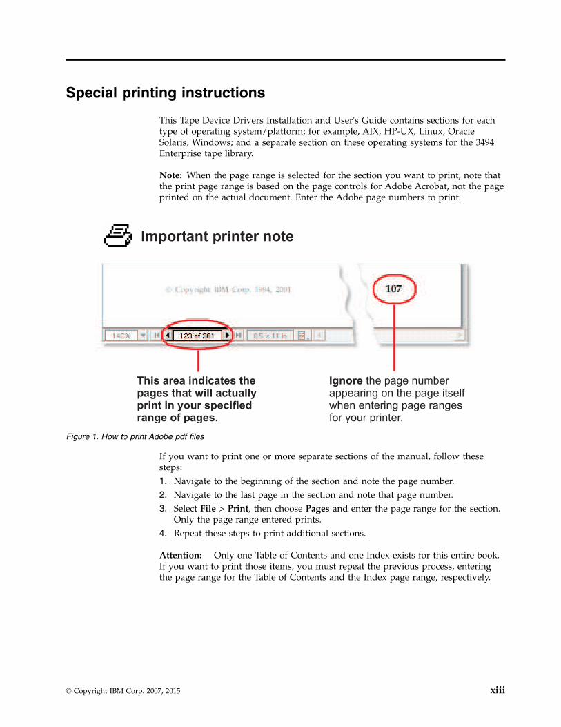
Note: When the page range is selected for the section you want to print, note thatthe print page range is based on the page controls for Adobe Acrobat, not the pageprinted on the actual document. Enter the Adobe page numbers to print.
If you want to print one or more separate sections of the manual, follow thesesteps:1. Navigate to the beginning of the section and note the page number.2. Navigate to the last page in the section and note that page number.3. Select File > Print, then choose Pages and enter the page range for the section.
Only the page range entered prints.4. Repeat these steps to print additional sections.
Attention: Only one Table of Contents and one Index exists for this entire book.If you want to print those items, you must repeat the previous process, enteringthe page range for the Table of Contents and the Index page range, respectively.
Important printer note
This area indicates thepages that will actuallyprint in your specifiedrange of pages.
Ignore the page numberappearing on the page itselfwhen entering page rangesfor your printer.
Figure 1. How to print Adobe pdf files
© Copyright IBM Corp. 2007, 2015 xiii

xiv IBM Tape Device Drivers: Installation and User's Guide

Contents
iii
Read this first . . . . . . . . . . .. v
Preface . . . . . . . . . . . . .. vii
Sending your comments . . . . . .. xi
Special printing instructions . . . .. xiii
Figures . . . . . . . . . . . . .. xix
Tables . . . . . . . . . . . . . .. xxi
Chapter 1. Introduction . . . . . . .. 1
Chapter 2. Common extended features . 5Path failover and load balancing. . . . . . .. 5
Automatic failover . . . . . . . . . .. 5Dynamic load balancing . . . . . . . .. 9
Dynamic Runtime Attributes . . . . . . .. 10Supported devices and feature codes . . . . .. 10Data encryption . . . . . . . . . . . .. 11
Tape and library requirements . . . . . .. 11Planning for application-managed tapeencryption . . . . . . . . . . . . .. 14Planning for system-managed tape encryption.. 14Planning for library-managed tape encryption .. 17Encryption feature codes . . . . . . . .. 18
Chapter 3. AIX Tape and MediumChanger device driver . . . . . . .. 19Product requirements . . . . . . . . . .. 19Installation and configuration instructions . . .. 19
Installation procedure . . . . . . . . .. 20Configuring Tape and Medium Changer devices 21Configuring limitations . . . . . . . .. 21Deconfiguring tape devices . . . . . . .. 22Deconfiguring Medium Changer devices . .. 22Uninstalling . . . . . . . . . . . .. 22
Tape drive, media, and device driver parameters .. 23Configuration parameters. . . . . . . .. 23Media parameters . . . . . . . . . .. 29
Special files . . . . . . . . . . . . .. 30Special files for tape devices . . . . . . .. 30Special files for Medium Changer devices . .. 31
Persistent Naming Support . . . . . . . .. 32Changing the logical name after initial boot .. 33
Control Path failover support for tape libraries .. 34Configuring and unconfiguring path failoversupport. . . . . . . . . . . . . .. 34Primary and alternative paths . . . . . .. 34
Querying primary and alternative pathconfigurations . . . . . . . . . . .. 35Configuring and unconfiguring primary andalternative devices . . . . . . . . . .. 35
Data Path failover and load balancing support fortape drives . . . . . . . . . . . . .. 36
Installing Data Path failover license key . . .. 36Configuring and unconfiguring path failoversupport. . . . . . . . . . . . . .. 36Primary and alternative paths . . . . . .. 37Querying primary and alternative pathconfiguration . . . . . . . . . . . .. 37Configuring and unconfiguring primary andalternative devices . . . . . . . . . .. 38
System-managed encryption . . . . . . . .. 38Device driver configuration . . . . . . .. 38Querying tape drive configuration. . . . .. 39Testing data encryption configuration andconnectivity . . . . . . . . . . . .. 39Error logging . . . . . . . . . . . .. 39Field support information . . . . . . .. 39
Problem determination . . . . . . . . .. 39Dump support . . . . . . . . . . .. 39Device and volume information logging . . .. 40Log file . . . . . . . . . . . . . .. 41Tape log utility . . . . . . . . . . .. 41Reservation conflict logging . . . . . . .. 41Error logging . . . . . . . . . . . .. 42Error log templates . . . . . . . . . .. 42Automatic dump facility . . . . . . . .. 44Dynamic Runtime Attributes . . . . . .. 44Trace facility . . . . . . . . . . . .. 45Atape System Trace (ATRC) utility . . . .. 45Component tracing . . . . . . . . . .. 45Atape Component Trace (ACTRC) utility . .. 46
Tape drive service aids . . . . . . . . .. 46Tape drive service aids details . . . . . .. 46
Performance considerations . . . . . . . .. 49Data path . . . . . . . . . . . . .. 49Common AIX utilities . . . . . . . . .. 49AIX iostat utility for tape performance . . .. 50Before Support is called . . . . . . . .. 50
Chapter 4. HP-UX Tape and MediumChanger device driver . . . . . . .. 51Product requirements . . . . . . . . . .. 51
ATDD implementation . . . . . . . .. 51Hardware requirements . . . . . . . .. 52Software requirements . . . . . . . . .. 52Software interface to the device driver . . .. 52
Installation and configuration instructions . . .. 53Configuration limitations . . . . . . . .. 53Installing and configuring PCI drivers . . .. 53
Supported configuration parameters . . . . .. 61Configuration parameter definitions . . . .. 62
© Copyright IBM Corp. 2007, 2015 xv

Special files . . . . . . . . . . . . .. 65Persistent Naming Support . . . . . . . .. 67Control Path failover support for tape libraries .. 67
Configuring and unconfiguring path failoversupport. . . . . . . . . . . . . .. 67Primary and alternative paths . . . . . .. 68Querying primary and alternative pathconfigurations . . . . . . . . . . .. 69Disabling and enabling primary and alternativepaths . . . . . . . . . . . . . .. 69
Data Path failover and load balancing support fortape drives . . . . . . . . . . . . .. 69
Configuring and unconfiguring path failoversupport. . . . . . . . . . . . . .. 70Primary and alternative paths . . . . . .. 71Querying primary and alternative pathconfiguration . . . . . . . . . . . .. 71Disabling and enabling primary and alternativepaths . . . . . . . . . . . . . .. 72
Problem determination . . . . . . . . .. 72Error logging . . . . . . . . . . . .. 72Sense data logging . . . . . . . . . .. 72Support_info script . . . . . . . . . .. 72Tracing facility . . . . . . . . . . .. 73Problems and solutions . . . . . . . .. 74
Chapter 5. Linux Tape and MediumChanger device driver . . . . . . .. 77Product requirements . . . . . . . . . .. 77Installation and Configuration instructions . . .. 77
Conventions used . . . . . . . . . .. 78Configuration limitations . . . . . . . .. 78Components created during installation . . .. 78Installation procedure . . . . . . . . .. 79Updating procedure . . . . . . . . .. 79Querying the installed package . . . . . .. 80Configuring Tape and Medium Changer deviceson Intel-compatible systems . . . . . . .. 80Configuring Tape and Medium Changer deviceson IBM System p models . . . . . . . .. 81Configuring Tape and Medium Changer deviceson IBM System z models . . . . . . . .. 81Uninstallation procedure . . . . . . . .. 83
Tape drive, media, and device driver parameters .. 83Configuration parameters. . . . . . . .. 83Nonchangeable parameters . . . . . . .. 84Changeable parameters . . . . . . . .. 85
Special files . . . . . . . . . . . . .. 89Special files for the tape device . . . . . .. 89Special files for the Medium Changer device .. 89Persistent Naming Support . . . . . . .. 90
Control Path failover support for tape libraries .. 92Configuring and unconfiguring path failoversupport. . . . . . . . . . . . . .. 92Enabling path failover for the sg interface . .. 93Primary and alternative paths . . . . . .. 93Querying primary and alternative pathconfiguration . . . . . . . . . . . .. 94Disabling and enabling primary and alternativepaths . . . . . . . . . . . . . .. 94
Data Path failover and load balancing support fortape drives . . . . . . . . . . . . .. 94
Enabling path failover for st and sg interface .. 95Primary and alternative paths . . . . . .. 96Querying primary and alternative pathconfiguration . . . . . . . . . . . .. 97Disabling and enabling primary and alternativepaths . . . . . . . . . . . . . .. 97Tape Reserve Type . . . . . . . . . .. 97
Open source device driver - lin_tape . . . . .. 97Comparing IBMtape and lin_tape . . . . .. 97Installation . . . . . . . . . . . .. 98Driver parameters and special device files . .. 98Taking devices offline and completingmaintenance . . . . . . . . . . . .. 98Path failover support . . . . . . . . .. 99lin_taped daemon . . . . . . . . . .. 99
System-managed encryption . . . . . . . .. 99Configuring device drivers . . . . . . .. 99Querying tape drive configuration . . . .. 100
Problem determination . . . . . . . . .. 101Tracing driver modules . . . . . . . .. 101Configuring and running the lin_taped daemon 101Reservation conflict logging . . . . . .. 106
Chapter 6. Solaris Tape and MediumChanger Device Driver . . . . . .. 107Product requirements. . . . . . . . . .. 107Installation and configuration instructions . . .. 108
Preventing conflicts with other device drivers 108Preinstallation considerations . . . . . .. 109Installing and updating IBMtape . . . . .. 109Configuring IBM tape devices with FibreChannel and SAS HBAs . . . . . . . .. 115Configuring limitations . . . . . . . .. 120Solaris Zones support . . . . . . . .. 120Configuration parameters . . . . . . .. 123Dynamic Runtime Attributes . . . . . .. 127Removing IBMtape . . . . . . . . .. 128Adding or removing devices . . . . . .. 128Unconfiguring tape devices. . . . . . .. 129Tapelist Utility Program . . . . . . . .. 129
Special files . . . . . . . . . . . . .. 131Device behaviors . . . . . . . . . .. 132File naming conventions. . . . . . . .. 132
Persistent Naming Support . . . . . . . .. 133Control Path failover support for libraries . . .. 135
Configuring and deconfiguring Path Failoversupport . . . . . . . . . . . . .. 135Primary and alternative paths . . . . . .. 135Querying primary and alternative pathconfiguration . . . . . . . . . . .. 136Disabling and enabling primary and alternativepaths . . . . . . . . . . . . . .. 136
Data Path failover and load balancing support fortape drives . . . . . . . . . . . . .. 136
Configuring and deconfiguring Path Failoversupport . . . . . . . . . . . . .. 136Primary and alternative paths . . . . . .. 138Querying primary and alternative pathconfiguration . . . . . . . . . . .. 138
xvi IBM Tape Device Drivers: Installation and User's Guide
||
||

Disabling and enabling primary and alternativepaths . . . . . . . . . . . . . .. 139
System-managed encryption . . . . . . .. 139Device driver configuration . . . . . .. 139Querying tape drive configuration . . . .. 140Testing data encryption configuration andconnectivity . . . . . . . . . . . .. 140Field support information . . . . . . .. 140
Problem determination . . . . . . . . .. 141Functional verification . . . . . . . .. 141Sense data logging . . . . . . . . .. 141Installation problems . . . . . . . . .. 142Tape monitor daemon (tmd) . . . . . .. 142Tracing facility . . . . . . . . . . .. 143Dynamic tracing utility . . . . . . . .. 145Setting the IBM_trace level for static tracing .. 145Running the diags_info script . . . . . .. 146iostat command . . . . . . . . . .. 146Reservation conflict logging . . . . . .. 146
Chapter 7. Windows Tape and MediumChanger device driver . . . . . .. 149Product requirements. . . . . . . . . .. 149Installation and configuration instructions . . .. 149
Windows Server 2012 instructions . . . .. 150Configuring limitations . . . . . . . .. 153
Persistent Naming Support on Windows Server2012 . . . . . . . . . . . . . . .. 153Control Path failover support for tape libraries .. 154
Configuring and unconfiguring Control Pathfailover support . . . . . . . . . .. 154Querying primary and alternative pathconfiguration . . . . . . . . . . .. 154Checking disablement of Control Path failoversetting. . . . . . . . . . . . . .. 154
Data Path failover support for tape drives . . .. 155Configuring and unconfiguring Data Pathfailover support . . . . . . . . . .. 155Reserve Type if DPF is disabled . . . . .. 155Querying primary and alternative pathconfiguration . . . . . . . . . . .. 155Checking disablement of Data Path failoversetting. . . . . . . . . . . . . .. 156
System-managed encryption . . . . . . .. 156Device driver configuration . . . . . .. 156Configuration file . . . . . . . . . .. 157Querying tape drive configuration settings .. 157
Problem determination . . . . . . . . .. 157Windows Server 2012 instructions . . . .. 157Reservation conflict logging . . . . . .. 158Max retry busy . . . . . . . . . . .. 159Checking if Data Path failover is enabled . .. 159Checking if Control Path failover is enabled .. 159
Old releases: V6.2.5.2 and prior releases . . .. 159
Chapter 8. 3494 Enterprise TapeLibrary support . . . . . . . . .. 165MTLIB program . . . . . . . . . . .. 165
Syntax and examples . . . . . . . . .. 165MTEVENT program . . . . . . . . . .. 175
Library driver information . . . . . . . .. 176Software interface . . . . . . . . . .. 176Library Manager event notification . . . .. 176Synchronous and asynchronous operations .. 176Operation Complete notification . . . . .. 176Unsolicited notification . . . . . . . .. 177Driver message queue . . . . . . . .. 177Volume categories . . . . . . . . . .. 177IBM TotalStorage Virtual Tape Server subsystemattachment . . . . . . . . . . . .. 178
3494 Library emulation . . . . . . . . .. 179Overview. . . . . . . . . . . . .. 1793494 Emulation design . . . . . . . .. 1793494 API Emulation and MTLIB program . .. 180SMC library names . . . . . . . . .. 180Volume categories . . . . . . . . . .. 180Asynchronous library operations . . . . .. 181Performance considerations. . . . . . .. 181
AIX . . . . . . . . . . . . . . .. 182Data flow . . . . . . . . . . . .. 182Product requirements. . . . . . . . .. 183Installation instructions . . . . . . . .. 183Special files . . . . . . . . . . . .. 1893494 Enterprise tape library attachment test .. 189Problem determination . . . . . . . .. 190
HP-UX . . . . . . . . . . . . . .. 191Data flow . . . . . . . . . . . .. 191Product requirements. . . . . . . . .. 192Installation instructions . . . . . . . .. 1933494 Enterprise tape library attachment test .. 197Problem determination . . . . . . . .. 197
Linux . . . . . . . . . . . . . . .. 197Data flow . . . . . . . . . . . .. 198Product requirements. . . . . . . . .. 198Installation instructions . . . . . . . .. 1993494 Enterprise tape library attachment test .. 202Problem determination . . . . . . . .. 202
Solaris . . . . . . . . . . . . . . .. 203Data flow . . . . . . . . . . . .. 203Product requirements. . . . . . . . .. 204Installation instructions . . . . . . . .. 2053494 Enterprise tape library attachment test .. 208Problem determination . . . . . . . .. 208
Windows . . . . . . . . . . . . . .. 209Data flow . . . . . . . . . . . .. 209Product requirements. . . . . . . . .. 210Installation instructions . . . . . . . .. 2113494 Enterprise tape library attachment test .. 215Problem determination . . . . . . . .. 215
Chapter 9. IBM Tape Diagnostic Tool(ITDT). . . . . . . . . . . . . .. 217Purpose . . . . . . . . . . . . . .. 217Accessing ITDT . . . . . . . . . . .. 218Supported systems . . . . . . . . . .. 218
Standard Edition (ITDT-SE). . . . . . .. 218Graphical Edition (ITDT-GE) . . . . . .. 219
Supported equipment . . . . . . . . .. 220IBM Tape Diagnostic Tool - Standard Edition . .. 221
Installing ITDT - Standard Edition . . . .. 221Starting ITDT - Standard Edition . . . . .. 225
Contents xvii
||||||

Standard Edition - known issues and limitations 228Standard Edition - Start menu commands . .. 232Standard Edition - Scan menu commands . .. 233Standard Edition - Tapeutil menu commands 252Standard Edition - Program options . . . .. 264Standard Edition - Tapeutil scripting commands 264
IBM Tape Diagnostic Tool - Graphical Edition .. 292Installing ITDT - Graphical Edition . . . .. 292Graphical Edition - known issues andlimitations . . . . . . . . . . . .. 293ITDT-GE user interface description . . . .. 294Graphical Edition - Scan menu commands .. 297Graphical Edition - visualizing log files. . .. 311Graphical Edition - Tapeutil menu commands 312
Appendix A. Accessingdocumentation and software online .. 327
Appendix B. Verifying correctattachment of your devices . . . .. 331
Appendix C. Managing the microcodeon the IBM tape drive . . . . . . .. 333
Notices . . . . . . . . . . . . .. 335
Index . . . . . . . . . . . . . .. 337
xviii IBM Tape Device Drivers: Installation and User's Guide

Figures
1. How to print Adobe pdf files . . . . .. xiii2. Current attachment array . . . . . . .. 23. Dual HBA and multi-port drives . . . . .. 64. Dual HBA and single-port drive . . . . .. 75. Single HBA and multi-port drive . . . . .. 86. Dual HBA and multi-port drives . . . . .. 87. Single HBA and multi-port drives . . . .. 98. Sample configuration file . . . . . . .. 169. Data flow for AIX Device Driver (Atape) 19
10. Data path for AIX device driver (Atape) 4911. Data flow for HP-UX device driver (ATDD) 5112. Data flow for Linux device driver (lin_tape) 7713. Data flow for Solaris Device Driver (IBMtape) 10714. Data flow for Windows device driver
(IBMmag) . . . . . . . . . . . .. 14915. Installation application in Windows Explorer 15116. Windows logo testing screen . . . . .. 15217. Warning screen . . . . . . . . . .. 16018. \checked folder . . . . . . . . . .. 16119. \checked folder . . . . . . . . . .. 16220. Syntax diagram for mtlib program . . .. 16621. 3494/SMC library data flow . . . . . .. 17922. LIBSMC and OS components . . . . .. 18023. Data flow for AIX 3494 Enterprise Tape
Library Driver . . . . . . . . . .. 18224. Data flow for HP-UX 3494 Enterprise tape
library driver . . . . . . . . . .. 19225. Data flow for Linux 3494 Enterprise tape
library driver . . . . . . . . . .. 19826. Data flow for Solaris 3494 Enterprise tape
library driver . . . . . . . . . .. 20427. Data flow for Windows 3494 Enterprise tape
library driver . . . . . . . . . .. 21028. Welcome/Startup screen . . . . . . .. 22229. License screen . . . . . . . . . .. 22230. Machine credentials screen . . . . . .. 22331. Installation progress screen . . . . . .. 22332. Installation complete screen . . . . . .. 22433. Start screen menu . . . . . . . . .. 23234. Scan screen menu . . . . . . . . .. 23335. Scan screen second menu . . . . . .. 23436. More scan options . . . . . . . . .. 235
37. Device List screen . . . . . . . . .. 23638. Data Delete question . . . . . . . .. 23839. Test running . . . . . . . . . . .. 23840. Test results . . . . . . . . . . .. 23941. Dump . . . . . . . . . . . . .. 24042. Firmware Update screen . . . . . . .. 24143. Scrollable Data screen . . . . . . . .. 24244. System Test results . . . . . . . . .. 24445. Full Write results . . . . . . . . .. 24646. Tape Usage screen . . . . . . . . .. 24747. Encryption Start screen . . . . . . .. 25048. TCP/IP screen: Read data . . . . . .. 25249. TCP/IP Port command . . . . . . .. 26050. TCP/IP Port command results . . . . .. 26151. Graphical Edition user interface . . . .. 29452. Graphical Edition preferences . . . . .. 29553. Graphical Edition interface . . . . . .. 29654. Main program menu items . . . . . .. 29655. Toolbar buttons . . . . . . . . . .. 29756. Scan . . . . . . . . . . . . .. 29857. Test . . . . . . . . . . . . . .. 29958. Test results . . . . . . . . . . .. 30059. Configure TCP/IP Ports . . . . . . .. 30160. Dump results . . . . . . . . . .. 30261. Check for Device Updates - FixCentral
components . . . . . . . . . . .. 30362. Check for Device Updates - code level 30463. Encryption . . . . . . . . . . .. 30464. Overwrite data?. . . . . . . . . .. 30665. Transfer size . . . . . . . . . . .. 30666. Tape Usage . . . . . . . . . . .. 30767. System Test . . . . . . . . . . .. 30868. Copy Services . . . . . . . . . .. 31169. Graphic Edition: log view . . . . . .. 31270. Tapeutil Control Center . . . . . . .. 31371. Command parameters . . . . . . .. 31372. Command parameter results . . . . .. 31473. Generic tapeutil scan . . . . . . . .. 31474. DD tapeutil scan . . . . . . . . .. 31575. Configure TCP/IP Ports command in the
Graphical Edition . . . . . . . . .. 325
© Copyright IBM Corp. 2007, 2015 xix
||||||

xx IBM Tape Device Drivers: Installation and User's Guide

Tables
1. Supported devices and feature codes . . .. 112. Interoperability between IPv4 and IPv6 clients
and servers . . . . . . . . . . .. 163. Feature codes (encryption) . . . . . .. 184. Special files for tape devices . . . . . .. 305. Special files for Medium Changer devices 326. Error description . . . . . . . . . .. 507. HP-UX: Device-specific parameter definitions 628. HP-UX: Driver-specific parameters (Global) 639. Special files . . . . . . . . . . .. 65
10. New special files in HP-UX 11i v3 . . . .. 6611. Trace flags . . . . . . . . . . . .. 7312. Problems, reasons, and solutions . . . .. 7413. Troubleshooting (problems and solutions) 7514. Linux: Components created during lin_tape
installation . . . . . . . . . . . .. 7815. Linux: Special files for IBM tape devices 8916. Attached changer devices . . . . . . .. 9317. Attached tape devices . . . . . . . .. 9618. Comparing IBMtape and lin_tape . . . .. 9819. Solaris: IBMtape components . . . . .. 10820. Solaris: IBMtape install or update . . . .. 11021. Solaris Device Driver - IBMtape - equipment
listing example 1 . . . . . . . . .. 11022. Solaris Device Driver - IBMtape - equipment
listing example 2 . . . . . . . . .. 11323. Solaris Device Driver - IBMtape - equipment
listing example 3 . . . . . . . . .. 11424. Solaris Device Driver - IBMtape - equipment
listing example 4 . . . . . . . . .. 11425. Solaris: configuration parameters recognized
by IBMtape . . . . . . . . . . .. 12526. IBM SCSI Tape/Medium Changer special files
for Solaris. . . . . . . . . . . .. 133
27. Solaris: Example of Control Path failoversupport command output . . . . . .. 136
28. Example of Data Path failover supportcommand output . . . . . . . . .. 138
29. Solaris: tracing facility . . . . . . .. 14330. Device query. . . . . . . . . . .. 16831. Volume query . . . . . . . . . .. 16932. Expanded volume query . . . . . . .. 16933. Expanded volume data with usage . . .. 16934. Inventory count data . . . . . . . .. 16935. Tape library device number . . . . . .. 17036. Expanded tape library device list . . . .. 17037. Library data . . . . . . . . . . .. 17138. Statistical data . . . . . . . . . .. 17239. Inventory query. . . . . . . . . .. 17340. Category inventory query . . . . . .. 17441. Reserve category command . . . . . .. 17442. Reserve category list . . . . . . . .. 17543. Category attribute list . . . . . . . .. 17544. Library address information . . . . .. 17545. SMIT main menu . . . . . . . . .. 18646. SMIT devices menu . . . . . . . .. 18647. SMIT tape drive menu . . . . . . .. 18748. SMIT tape drive type menu . . . . . .. 18749. Add an LMCP Logical Device menu . . .. 18750. LMCP COMMAND STATUS window 18851. Configure an LMCP selection list . . . .. 18852. Configure a Defined LMCP COMMAND
STATUS window . . . . . . . . .. 18853. Codes and root causes . . . . . . .. 24854. Abort code definitions . . . . . . .. 25055. Device addressing . . . . . . . . .. 25456. Supported platforms . . . . . . . .. 27957. Driver descriptions . . . . . . . .. 328
© Copyright IBM Corp. 2007, 2015 xxi

xxii IBM Tape Device Drivers: Installation and User's Guide
Chapter 1. Introduction
This publication describes the IBM Tape and Medium Changer Device Drivers andIBM Tape Diagnostic Tool (ITDT) for various operating systems. Not all devices aresupported by all operating systems, drivers, or ITDT. Refer to the HardwareRequirements section for details.
Purpose
The IBM tape and medium changer device drivers are designed specifically to takeadvantage of the features that are provided by the IBM tape drives and mediumchanger devices. The goal is to give applications access to the functions requiredfor basic tape functions (such as backup and restore) and medium changeroperations (such as cartridge mount and unmount), and to the advanced functionsneeded by full tape management systems. Whenever possible, the driver isdesigned to take advantage of the device features transparent to the application.
The most current information on hardware and software requirements for IBMtape and medium changer device drivers can be found in the individual platformreadme files or with the subsequent links.
Hardware requirements
The tape drivers are developed to support various versions of different platforms.For the latest support, refer to the Interoperation Center website -http://www.ibm.com/systems/support/storage/config/ssic/.
Note: A single Fibre Channel host bus adapter (HBA) for concurrent tape and diskoperations is not recommended. Tape and disk devices require incompatible HBAsettings for reliable operation and optimal performance characteristics. Under stressconditions (high I/O rates for either tape, disk, or both) where disk and tapesubsystems share a common HBA, stability problems are observed. These issuesare resolved by separating disk and tape I/O streams onto separate HBAs and byusing SAN zoning to minimize contention. IBM is focused on assuringserver/storage configuration interoperability. It is strongly recommended that youroverall implementation plan includes provisions for separating disk and tapeworkloads.
For information about this issue, see the following Redbook, section 4.1.3 inhttp://www.redbooks.ibm.com/abstracts/sg246502.html?Open.
Software requirements
If you use a third-party application, consult with your application provider aboutthe compatibility with IBM tape device drivers.
For detailed driver requirements for each operating system, refer to the appropriatechapter. To obtain the most current service and documentation for this software,refer to Appendix A, “Accessing documentation and software online,” on page 327.
© Copyright IBM Corp. 2007, 2015 1

IBM tape products
The IBM tape product family provides an excellent solution for customers withsmall to large storage and performance requirements.1. IBM Virtualization Engine TS75202. IBM Virtualization Engine TS76503. IBM TS2230/TS2240/TS2250/TS2260/TS2270 tape drive4. IBM TS2340/TS2350/TS2360 tape drive5. IBM 3580 (Ultrium) tape drive (Model L33)6. IBM TS1140/TS1150 tape drive (Enterprise)7. IBM TS1120/TS1130 tape drive (Enterprise)8. IBM TS3200 tape library9. IBM TS3500 and TS4500 tape library (also known as IBM UltraScalable tape
library 3584)10. IBM TS3310 tape library11. IBM TS3100 tape library
The image illustrates the attachment of various current products to an opensystems server.
1
2
3
4
5
6
System Storage
7
89
System Storage
dd000005
10
Figure 2. Current attachment array
2 IBM Tape Device Drivers: Installation and User's Guide
|

▌1▐ Open Systems Server ▌6▐ IBM TS1120/TS1130/TS1140/TS1150 tapedrive [also known as Enterprise]
▌2▐ IBM Virtualization EngineTS7520/TS7530
▌7▐ IBM TS3200 tape library
▌3▐ IBM Virtualization Engine TS7650 ▌8▐ IBM TS3500 or TS4500 tape library
▌4▐ IBM TS2230/TS2240/TS2250/TS2260/TS2270 Ultrium 3/4/5/6/7 Half Height tapedrive
▌9▐ IBM TS3310 tape library
▌5▐ IBM TS2340/TS2350/TS2360 (or 3580)Ultrium 3/4/5/6 Full Height tape drive
▌10▐ IBM TS3100 tape library
Chapter 1. Introduction 3

4 IBM Tape Device Drivers: Installation and User's Guide
Chapter 2. Common extended features
Purpose
This chapter provides general information about the IBM device drivers,requirements, and advanced functionality.
Path failover and load balancing
Device driver path failover support configures multiple physical paths to the samedevice within the device driver and provides two basic functions:1. Automatic failover to an alternate physical path when a permanent error occurs
on one path.2. Dynamic load balancing for tape devices by using multiple host bus adapters
(HBA).
Path failover is supported on certain tape products with the latest IBM devicedrivers available on the following website - http://www.ibm.com/support/fixcentral. Instructions for downloading drivers can be found in Appendix A,“Accessing documentation and software online,” on page 327. Some devicesrequire a path failover feature code to be installed before path failover support isenabled in the device driver. Refer to “Supported devices and feature codes” onpage 10 for a list of supported devices and what path failover feature code isrequired for your machine type.
At startup or configuration, the system detects multiple logical devices of the tapedrive. Each logical device is a physical path to the same tape drive. A backup andrestore application can open and use only one logical device at a time because theyrepresent the same physical device.
Without path failover support, if a permanent path error occurs (because of anHBA or cable failure, for example), the application fails. It is possible to initiatemanual failover by restarting the application on the alternate logical device, but theapplication must be restarted from the beginning. A long backup or restoreoperation might be in progress when the path error occurred. Sometimes manualfailover requires operator intervention to reset the drive because a SCSIReservation might still exist on the failing HBA path.
When path failover support is enabled on all logical devices, the device driverconfigures them internally as a single device with multiple paths. The applicationcan still open and use only one logical device at a time. If an application opens theprimary device and a permanent path error occurs, the device driver initiatesfailover error recovery automatically on an alternate path. If successful, the currentoperation continues on an alternate path without interrupting the application. Thedata path failover error recovery first restores the previous device state, SCSIReservation, and tape position. Then, it tries the failing operation again.
Automatic failover
The automatic failover support provides error recovery on an alternate path whena permanent error occurs on the primary path. This support is transparent to therunning application. The two types of path failover are Data Path failover (DPF)
© Copyright IBM Corp. 2007, 2015 5

and Control Path failover (CPF). They are closely related. However, the differenceis that DPF is an automatic failover support for the transfer of data, whichprovides error recovery for systems that are connected to tape drives. CPF is anautomatic failover support for the transfer of commands to move tape cartridges.Examples of different configurations that can be constructed follow.
Data path failover
The following flowcharts outline the different types of configurations for data pathfailover (DPF). These configurations are presented in order of best practices asrecommended by IBM.
Dual Host Bus Adapters (HBAs) to a multi-port drive
Consider a multipath connection that consists of two Host Bus Adapters (HBAs)connected through a fabric to a multi-port drive.
As seen in Figure 3, four available paths are available between the drive and thehost system. These paths are
HBA A to drive port 1 [A, p1]HBA A to drive port 2 [A, p2]HBA B to drive port 1 [B, p1]HBA B to drive port 2 [B, p2]
One path is the primary path and the other three are alternate paths. If [A, p1] isthe primary path and if HBA A fails, two valid paths ([B, p1] and [B, p2]) remain.The DPF tries to switch to one of the available configured paths. Conversely, if thecable to port 1 of the drive fails with [A, p1] as the primary path, two valid pathsto the drive [A, p2] and [B, p2] are still available. Without DPF support, if apermanent path error occurs (because of HBA or cable failover, for example), theapplication fails. With DPF, if the permanent failure occurs with this configuration,two valid physical paths for the data are still available for transmitting data. Therunning application is not affected.
If the path that failed is restored, the device driver claims the path as available anduses it as a valid alternate path in most conditions. This action is dependent on
Drive
LibraryController
Drive
Drive
Dual HBA
Mulit-Port Drive
Fabric
Virtual Tape Library
a2500255
Multi-Port DriveIn Library
12
A B
Figure 3. Dual HBA and multi-port drives
6 IBM Tape Device Drivers: Installation and User's Guide

Operating System and HBA behavior, not the IBM tape device driver behavior.
Dual Host Bus Adapters (HBAs) to a single-port drive
Consider a multipath connection that consists of two HBAs connected through afabric to a single-port device.
This configuration supplies two physical paths to the same device. However, if theport or cable from the device fails, the automatic failover does not work. Thatconnection is severed and a permanent path error occurs. If, however, the failurewas with one of the HBAs or their cables, the automatic data path failover selectsthe other HBA. Then, the information continues through the alternate path. Anexample here is with the connections [A, p1] and [B, p1]. If [A, p1] is the primarypath and a failure occurs with the HBA or HBA cable, then DPF automaticallymoves the connection to [B, p1] without affecting the application.
Single Host Bus Adapters (HBA) to a multi-port drive
Consider a single path from the HBA through the fabric to a multi-port device.
Drive
LibraryController
Drive
Drive
Dual HBASingle-Port Drive
Fabric
Virtual Tape Library
a2500256
Single Port DriveIn Library
1
A B
Figure 4. Dual HBA and single-port drive
Chapter 2. Common extended features 7

This configuration also provides a failover path unless the failure is with the HBAor the HBA’s cable. At which point, the connection is severed and a permanentpath error occurs. Whereas, if the failure occurs on the device side, an alternativepath is still available for the information to go through which DPF automaticallyfailovers to.
Control path failover
The following flowcharts outline the different types of configurations for controlpath failover (CPF). These configurations are presented in order of best practices asrecommended by IBM.
Dual Host Bus Adapters (HBAs) to multi-port drives
Consider a multipath connection that consists of two Host Bus Adapters (HBAs)connected through a fabric to the library by at least two drives.
As seen in Figure 6, four available paths are available between the drive and thehost system. These paths are
HBA A to drive 1 [A, d1]HBA A to drive 2 [A, d2]HBA B to drive 1 [B, d1]HBA B to drive 2 [B, d2]
Drive
LibraryController
Drive
Drive
Single HBA
Mulit-Port DriveIn Library
Fabric
Virtual Tape Library
a2500257
Mulit-Port Drive1
2
A
Figure 5. Single HBA and multi-port drive
Drive 1LibraryControllerDrive 2
Fabric
Virtual Tape Library
a2500293
Dual HBA
A
Control Path Failover (CPF)Dual HBA Multi Drives
B
Library
Figure 6. Dual HBA and multi-port drives
8 IBM Tape Device Drivers: Installation and User's Guide

As with DPF, one path is the primary path and the other three are alternate paths.If [A, d1] is the primary path and if HBA A fails, two remaining valid paths ([B,d1] and [B, d2]) are still available. The CPF attempts to switch to one of theavailable configured paths. Conversely, if the cable to drive 1 or drive 1 fails with[A, d1] as the primary path, two valid paths to the drive ([A, d2] and [B, d2]) areavailable. Without CPF support, if a permanent path error occurs (because of HBAor cable failover, for example), the application fails. With CPF, if a permanentfailure with this configuration occurs, two valid physical paths are available for thedata to be transmitted. Also, the running application is not affected.
If the failed path is restored, the device driver claims the path as available anduses it as a valid alternate path in most conditions. This action is dependent onOperating System and HBA behavior, not the IBM tape device driver behavior.
Note: In the operating systems logs, reservation conflict information might appear,which is because of scsi2 reservations that are not cleared. However, the devicedriver continues to try any paths that are available to make the reservation conflicttransparent to the operating system.
Single Host Bus Adapter (HBA) to multi-port drives
Consider a single path from the HBA through the fabric to two drives in a library.
This configuration also provides a failover path unless the failure is with the HBAor the HBA’s cable. At which point, the connection is severed and a permanentpath error occurs. Whereas, if the failure occurs with a drive or a drive’s cable, analternative path is still available for the information to go through which CPFautomatically failovers to.
Dynamic load balancing
The dynamic load balancing support optimizes resources for tape devices that havephysical connections to multiple host bus adapters (HBA) in the same machine.When an application opens a device that has multiple configured HBA paths, thedevice driver determines which path has the HBA with the lowest usage. Then, itassigns that path to the application. When another application opens a differentdevice with multiple HBA paths, the device driver again determines the path withthe lowest HBA usage. Then, that path is assigned to the second application. Thedevice driver updates the usage on the HBA assigned to the application when thedevice is closed. Dynamic load balancing uses all host bus adapters wheneverpossible and balance the load between them to optimize the resources in themachine.
Drive 1LibraryControllerDrive 2
Fabric
Virtual Tape Library
a2500292
Single HBA
A
Control Path Failover (CPF)Single HBA Multi Drives
Library
Figure 7. Single HBA and multi-port drives
Chapter 2. Common extended features 9

For example, consider a machine with two host bus adapters, HBA1 and HBA2,with multiple tape drives attached. Each tape drive is connected to both HBA1 andHBA2. Initially, there are no tape drives currently in use. When the first applicationopens a tape drive for use, the device driver assigns the application to use HBA1.When a second application opens a tape drive for use, the device driver assignsthe second application to use HBA2. A third application is assigned to HBA1 and afourth application is assigned to HBA2. Two applications are assigned to HBA1and two applications are assigned to HBA2.
If the first application finishes and closes the device, there is now one applicationwith HBA1 and two applications with HBA2. When the next application opens atape drive, it is assigned to HBA1, so again there are two applications with HBA1and two applications with HBA2. Likewise, if the second application finishes andcloses the device, HBA2 has one application that is assigned to it. The nextapplication that opens a tape drive is assigned to HBA2.
The dynamic load balancing support is independent from the automatic failoversupport. Regardless of the path that is assigned initially for load balancing, if thatpath fails, the automatic failover support attempts recovery on the next availablepath.
Dynamic Runtime Attributes
There are frequently field issues where customers must know which Initiator isholding a reservation in a drive or preventing the media from being unloaded.Also, they must correlate which drive special file name is used for the drive (suchas rmt2). Sometimes this issue occurs over transport bridges and translators, losingany transport identifiers to help in this effort. LTO5, 3592 E07 (Jag 4) and laterphysical tape drives support attributes that are set to the drive dynamically by ahost. This function is called Dynamic Runtime Attributes (DRA).
This feature is enabled by default. The attributes are set in the drive by the hostduring open, close, device reset, and data path change only. If there is a problemwith sending the attributes to the drive, the error is ignored and not returned tothe application.
There is no ioctl in the IBM tape drivers to retrieve the dynamic runtime attributesbut is an upcoming command on ITDT. The attributes can also be retrievedthrough a pass through ioctl to issue Read Dynamic Runtime Attributes SCSIcommand (see applicable IBM Tape Drive SCSI Reference). See the host platformsection for any special information that pertains to the driver that concerns DRA. Ifthere is a question whether your driver level supports DRA, see the fixlist thatcomes with your driver to see whether it was added. Updates are also requiredwith the drive firmware.
Supported devices and feature codes
Path failover is supported only for the devices that are listed in Table 1 on page 11.Path failover includes Control Path failover (CPF) for tape libraries and Data Pathfailover (DPF) for tape drives. To use path failover support, some devices requirefeature codes as listed in Table 1 on page 11.
10 IBM Tape Device Drivers: Installation and User's Guide

Table 1. Supported devices and feature codes
Supported tape library/drive Feature code (FC), if required
TS3500 and TS4500 Standard, no FC required (DPF)FC 1682 (CPF)
TS3400/3592 Standard, no FC required (DPF)FC 1682 (CPF)
TS3310/LTO FC 1682 (CPF and DPF)
TS3200/LTO FC 1682 (CPF and DPF)
TS3100/LTO FC 1682 (CPF and DPF)
TS7520/All FC 1682 (CPF and DPF)
TS7650/All Standard, no FC required (CPF and DPF)
3583 FC 1680 (CPF), FC 1681 (DPF)
3582 FC 1680 (CPF), FC 1681 (DPF)
Note:
1. Path failover is not supported on parallel SCSI (except for some parallel SCSIdrives on AIX® operating systems). Path failover is only supported on SASdevices that are attached to Windows and Linux for Intel/AMDprocessor-based servers. SAS is not supported on System p® servers (AIX andLinux).
2. Path failover is not supported on Virtual Tape Libraries (except for the librariesthat are listed in Table 1) that emulate IBM tape devices.
3. If your device does not support path failover, you must disable this option inthe device driver. See the specific platform section for driver default behaviorand enable/disable failover instructions.
Data encryption
Tape and library requirements
The LTO Ultrium 4 and later tape drives support host Application ManagedEncryption (AME), Library Managed Encryption (LME), and System ManagedEncryption (SME), by using T10 encryption methods, for SAS and Fibre Channeldrives only. Data encryption is supported by LTO Ultrium 4 and later DataCartridges only. Encryption is also supported by library firmware version 4.0 orhigher.
The encryption-enabled drive contains the necessary hardware and firmware toencrypt and decrypt host tape application data. Encryption policy and encryptionkeys are provided by the host application or host server. A drive digital certificateis installed at manufacturing time. Each drive receives a unique serial number andcertificate. The T10 application can validate each drive instance by checking thedrive's digital certificate.
The IBM TS1120 (3592 Model E05) and newer tape drives can encrypt data as it iswritten to their supporting IBM 3592 Enterprise Tape Cartridges, including WORMcartridges. The IBM TS1040 LTO Ultrium 4 and newer Ultrium tape drives can alsoencrypt data as it is written to any LTO 4 or newer data cartridge. Encryption iscompleted at full line speed in the tape drive after compression. (Compression ismore efficiently done before encryption.) This new capability adds a strong
Chapter 2. Common extended features 11
|
|

measure of security to stored data without the processing overhead andperformance degradation that is associated with encryption done on the server orthe expense of a dedicated appliance.
The IBM TS4500 does not support SME for LTO. For specific encryption support,refer to SSIC at http://www.ibm.com/systems/support/storage/config/ssic/.
The following three major elements comprise the tape drive encryption solution.v The encryption-enabled tape drive
The 3592 Model E07 and newer model tape drives, and the LTO Ultrium 4 andnewer Ultrium drives are encryption capable. All TS1120 Model E05 tape driveswith Feature code 5592 or 9592 are encryption capable. They are functionallycapable of completing hardware encryption, but this capability is not yetactivated. To run hardware encryption, the tape drives must beencryption-enabled. Encryption can be enabled on the encryption-capable tapedrives through the Tape Library Specialist Web interface. Refer to theappropriate section in the documentation for your library for information abouthow to enable encryption.
Note: FC 1604, Transparent LTO Encryption, is required to use system-managedor library-managed encryption on LTO Ultrium 4 and newer tape drives. It isnot required for application-managed encryption. Refer to the sections on eachmethod of encryption for information.
v Encryption key management
Encryption involves the use of several kinds of keys, in successive layers. Howthese keys are generated, maintained, controlled, and transmitted depends uponthe operating environment where the encrypting tape drive is installed. Somedata management applications, such as Tivoli® Storage Manager, can run keymanagement. For environments without such applications or whereapplication-agnostic encryption is wanted, IBM provides a key manager (such asthe Tivoli Key Lifecycle Manager or the IBM Security Key Lifecycle Manager) tocomplete all necessary key management tasks.
v Encryption policy
The method that is used to implement encryption. It includes the rules thatgovern which volumes are encrypted and the mechanism for key selection. Howand where these rules are set up depends on the operating environment.
The LTO Ultrium 6 and later encryption environment is complex and requiresknowledge beyond that of product trained Service Support Representatives (SSRs).The Encryption function on tape drives (desktop, stand-alone, and within libraries)is configured and managed by the customer. In some instances, SSRs are requiredto enable encryption at a hardware level when service access or service passwordcontrolled access is required. Customer setup support is by Field Technical SalesSupport (FTSS), customer documentation, and software support for encryptionsoftware problems. Customer 'how to' support is also provided with a support linecontract.
In the open system environment, there are three methods of encryptionmanagement to choose from. These methods differ in where you choose to locateyour encryption key manager application. Your operating environment determineswhich is the best for you, with the result that key management and the encryptionpolicy engine might be in any one of the three environmental layers: applicationlayer, system layer, and library layer.
12 IBM Tape Device Drivers: Installation and User's Guide
||
|
Application-managed tape encryption
This method is best where operating environments run an application alreadycapable of generating and managing encryption policies and keys, such as TivoliStorage Manager (TSM). Policies specifying when encryption is to be used aredefined through the application interface. The policies and keys pass through thedata path between the application layer and the Encryption is the result ofinteraction between the application and the encryption-enabled tape drive, and istransparent to the system and library layers.
Refer to“Planning for application-managed tape encryption” on page 14 for detailson the hardware and software requirements for application-managed encryption.For details on setting up application-managed tape encryption refer to the TivoliStorage Manager documentation or for information, visit the following site -http://publib.boulder.ibm.com/infocenter/tivihelp/v1r1/index.jsp
It is required to use the latest device drivers available. Refer to Appendix A,“Accessing documentation and software online,” on page 327 for downloadingdrivers.
System-managed tape encryption
In this method, key generation and management are completed by an encryptionkey manager (EKM). Policy controls and keys pass through the data path betweenthe system layer (device drivers) and the encryption-capable tape drives.Encryption is transparent to the applications.
Note: The abbreviation EKM for the driver configuration file is used generically torefer to any encryption key manager.
It is required to use the latest device drivers available on the website. SeeAppendix A, “Accessing documentation and software online,” on page 327 forinstructions.
Refer to “Planning for system-managed tape encryption” on page 14 for details onthe hardware and software requirements for system-managed encryption. Fordetails on setting up system-managed encryption in different operating systemenvironments, refer to the applicable chapter for each operating system.
Library-managed tape encryption
This method is best for encryption-capable tape drives in open attached IBM tapelibraries. Scratch encryption policies that specify when to use encryption are set upthrough the IBM Tape Library Specialist Web interface. Policies are based oncartridge volume serial numbers. Key generation and management are run by anencryption key manager. Policy control and keys pass through the library-to-driveinterface, therefore encryption is transparent to the applications.
Refer to“Planning for library-managed tape encryption” on page 17 for details onthe hardware and software requirements for library-managed encryption. Fordetails on setting up library-managed encryption on encryption-capable tapedrives, refer to the IBM Tape Library Operator's Guide for your library.
Chapter 2. Common extended features 13

Planning for application-managed tape encryption
Note: Contact your IBM representative for information about encryption on theIBM encryption-capable tape drive.
To run encryption on the encryption-capable tape drive, the following is required.v Encryption-capable tape drivev Encryption configuration features:
– Library code updates and Transparent LTO Encryption feature code forencryption-capable libraries
– Tape drive code updates
Application-managed tape encryption setup tasks
Any task that is not identified as an IBM service task is the responsibility of thecustomer.1. Install, cable, and configure the encryption-capable tape drive (refer your IBM
Tape Drive or Library Operator's Guide)2. Install appropriate IBM tape device driver level (Atape, for example).3. Set up encryption policies. Refer to the appropriate Tivoli Storage Manager
documentation.4. Perform write/read operation to test encryption.5. Verify encryption of the test volume by Autonomic Management Engine
(AME): issue QUERY VOLUME FORMAT=DETAILED
Verify that Drive Encryption Key Manager is set to Tivoli Storage Manager.
Planning for system-managed tape encryption
Note: Contact your IBM representative for information about encryption on theIBM encryption-capable tape drive.
To run encryption on the encryption-capable tape drive, the following is required.v Encryption-capable tape drivev Keystore (Refer to documentation on Tivoli Key Lifecycle Manager (TKLM))v Encryption configuration features:
– Tivoli Key Lifecycle Manager (TKLM)– Tape drive code updates and Transparent LTO Encryption feature code for
encryption-capable libraries– Tape system library code updates
Setup tasks for system-managed tape encryption on OpenSystems operating system
Any task that is not identified as an IBM service task is the responsibility of thecustomer.1. Install, verify, and configure
a. Keystoreb. EKM (Refer to documentation on Tivoli Key Lifecycle Manager (TKLM))
Note: The SSL protocol in TKLM is not supported by SME.
14 IBM Tape Device Drivers: Installation and User's Guide

2. Install, cable, and configure encryption-capable tape drive (refer to your IBMTape Drive or Library Operator's Guide).
3. Install and enable appropriate device driver level (refer to the appropriateoperating system chapter in this document for details).
4. Edit the /etc/ibmekm.conf file.5. Use “[38] Test Encryp. Path (Test Encryption Key Path/Setup)” on page 259 or
“Test Encryption Path” on page 323 to verify.
System-managed encryption configuration
Note: The tape drive must be set to system-managed encryption from the drivepanel or library user interface before device driver system-managed encryption isused.
After the device driver is installed, then an encryption key manager must beconfigured. The servers are configured in a text file ibmekm.conf that is installedin the /etc directory by the device driver if a current configuration file does notexist.
Figure 8 on page 16 is an example of the sample configuration file installed.
Chapter 2. Common extended features 15

The following shows the different entry formats for IPv4 and IPv6 addresses in theibmekm.conf configuration file:v IPv4 format: EKMserver timeout IPv4_address Port_number
v IPv6 format: EKMserver timeout IPv6_address Port_number
To set up an IP address for an encryption key manager server, use Table 2 tochoose an appropriate IP address type. Then, add the IP address in the entry of theencryption configuration file.
Table 2. Interoperability between IPv4 and IPv6 clients and servers
IPv4 EKMserver IPv4-onlyhost
IPv6 EKMserver IPv6-onlyhost
IPv4 EKMserverdual-stack host
IPv6 EKMserverdual-stack host
IPv4Client/IPv4-onlyhost
IPv4 (no) IPv4 IPv4
# IBM Encryption Key Manager Configuration File## (C) COPYRIGHT International Business Machines Corp. 2006# All Rights Reserved# Licensed Materials - Property of IBM## US Government Users Restricted Rights - Use, duplication or# disclosure restricted by GSA ADP Schedule Contract with IBM Corp.## This file contains the TCP/IP address(s) and port(s) for the Encryption Key# Server with a configuration entry in the following formats. The IPv4 address# entered as x.x.x.x:port. The IPv6 address entered as x:x:x:x:x:x:x:x port.# The server is for information only and is not used. The timeout value is# specified in seconds.## The format for IPv4 address:# server timeout address:port# for example,# ekmtest 10 9.12.123.1234:8050## The format for IPv6 address:# server timeout address port# for example,# ekmtest 10 fe80::207:30ee:edcb:d05d 8050## The Encryption Key Server address and port can be a local loop back# address 127.0.0.1:port in IPv4 format or ::1 port in IPv6 format if the server# is on the same host or a network address and port if external to the host.# Up to 16 server address and port entries are supported if there are multiple# TCP/IP connections to the same server and/or multiple servers.## Interoperability between IPv4 and IPv6 versions running on dual-stack hosts:# IPv4 Client <--> IPv4/IPv6 Server using IPv4 address for EKM server# IPv6 Client <--> IPv4 Server using IPv4 address for EKM server# IPv6 Client <--> IPv6 Server using IPv6 address for EKM server## Sample entry for a local server with a 10 second timeout using port 8050# in IPv4 format# ekmtest 10 127.0.0.1:8050## in IPv6 format# ekmtest 10 ::1 8050
Figure 8. Sample configuration file
16 IBM Tape Device Drivers: Installation and User's Guide

Table 2. Interoperability between IPv4 and IPv6 clients and servers (continued)
IPv4 EKMserver IPv4-onlyhost
IPv6 EKMserver IPv6-onlyhost
IPv4 EKMserverdual-stack host
IPv6 EKMserverdual-stack host
IPv6Client/IPv6-onlyhost
(no) IPv6 (no) IPv6
IPv4 Clientdual-stack host
IPv4 (no) IPv4 IPv4
IPv6 Clientdual-stack host
IPv4 IPv6 (no) IPv6
The timeout value in seconds is used when a request is sent to the server and thetime for the server to respond in case no response is received.
A maximum of 16 server connections are configured for failover. When aconnection cannot be made or is lost on the current server that is used, theoperation is tried again on the next configured server.
After servers are configured in the ibmekm.conf file, then specific tape drivesmust be configured to the device driver for system-managed encryption. Thedevice driver default does not enable encryption. Refer to the following sectionsfor specific information, depending on the operating system.
Planning for library-managed tape encryption
Note: Contact your IBM representative for information about encryption on theIBM encryption-capable tape drive.
To complete encryption on the encryption-capable tape drive, the following isrequired.v Encryption-capable tape drivev Keystore (Refer to documentation on Tivoli Key Lifecycle Manager (TKLM))v Encryption configuration features:
– Tivoli Key Lifecycle Manager (TKLM)– Tape system library code updates and Transparent LTO Encryption feature
code for encryption-capable libraries– Tape drive code updates
Library-managed tape encryption tasks
Any task that is not identified as an IBM service task is the responsibility of thecustomer.1. Install, verify, and configure
a. Keystoreb. EKM (Refer to documentation on Tivoli Key Lifecycle Manager (TKLM)) for
information on both.2. Install and cable the encryption-capable tape drive (IBM service task for TS1120
Tape Drive).3. Use IBM tape library specialist to enable the tape drive for library-managed
tape encryption (refer to your IBM Tape Drive or Library Operator's Guide).
Chapter 2. Common extended features 17

4. Use library diagnostic functions to verify.
Bulk rekey
For customers with Library-Managed Encryption with 3592 Enterprise tape drivesand IBM tape and changer drivers that are running on open systems operatingsystem (AIX, HP-UX, Linux, Solaris, Windows), sample code for completing bulkrekey operations is available. The sample code packages are provided "as-is" withlimited testing, and are provided to give customers guidance on bulk rekeyoperations.
For UNIX operating systems, a sample script (rekey_unix.sh) is provided and mustbe used with the tapeutil version that is bundled in the same package. ForWindows operating systems, a sample c program (rekey_win.c) is provided. Bothof these sample programs must be used with both the IBM tape and changerdrivers. In addition, data cartridges must be in storage cells, not in I/O stationcells or tape drives.
For information and to download the sample code packages, seehttp://www.ibm.com/support/fixcentral/.
Encryption feature codes
To use system-managed and library-managed encryption, the Transparent LTOEncryption feature codes that are listed in Table 3 are required for the associatedIBM tape libraries with encryption-capable tape drives. If the drives in use areTS1120 tape drives, this feature code is not required for system-managed orlibrary-managed encryption. If you are using application-managed encryption, nofeature code is required on any encryption-capable tape drives.
Table 3. Feature codes (encryption)
Tape library Feature code
TS4500 FC 1604
TS3500 FC 1604
TS3400 Standard Feature
TS3310 FC 5900
TS3100/3200 FC 5900
18 IBM Tape Device Drivers: Installation and User's Guide

Chapter 3. AIX Tape and Medium Changer device driver
This chapter describes the IBM AIX Enhanced Tape and Medium Changer DeviceDriver (Atape) for IBM tape devices.
Purpose
The IBM AIX Enhanced Tape and Medium Changer device driver is designed totake advantage of the features that are provided by the IBM tape drives andmedium changer devices. The goal is to give applications access to the functionsrequired for basic tape operations (such as backup and restore) and mediumchanger operations (such as mount and unmount the cartridges), and to theadvanced functions needed by full tape management systems. Whenever possible,the driver is designed to take advantage of the device features transparent to theapplication.
Data flow
The software that is described in this chapter covers the AIX Enhanced DeviceDriver (Atape device driver) and the interface between the application and thetape device. For data flow, refer to Figure 9.
Product requirements
Hardware requirements
Refer to “Hardware requirements” on page 1 the latest hardware that is supportedby the Atape device driver.
Software requirements
The AIX Enhanced device driver (Atape device driver) supports AIX 5L™ Version5.3 and later releases on IBM POWER-based AIX servers.
For current software requirements, refer to the “Software requirements” on page 1.
Installation and configuration instructions
The recommended procedure for installing a new version of the device driver is touninstall the previous version.
Instructions for uninstalling the device driver are outlined in “Uninstalling” onpage 22.
Figure 9. Data flow for AIX Device Driver (Atape)
© Copyright IBM Corp. 2007, 2015 19
1. At the end of the installation procedure, the installp facility automatically runsthe AIX bosboot command to update the boot record with the newly installedAtape files. When the bosboot command completes, the following messages aredisplayed:0503-292 This update does not fully take effect until after a system reboot.installp: bosboot process completed.
This message refers to the updates to the boot record only. If the installationsummary shows that the Atape driver was installed successfully, it is notnecessary to reboot the machine currently.If the installation summary shows that the installation failed, you must rebootthe machine and attempt to install the Atape driver a second time.
2. During the Atape install, the following entries are entered into the two systemfiles.v /usr/lpp/bosinst/cdfs.optional.list to help the system image backup to
DVD/CD mediaThe entry list in /usr/lpp/bosinst/cdfs.optional.list:/usr/lib/drivers/Atape /usr/lib/drivers/Atape Atape.driver/usr/lib/methods/cfgAtape /usr/lib/methods/cfgAtape Atape.driver/usr/lib/methods/ucfgAtape /usr/lib/methods/ucfgAtape Atape.driver/usr/lib/methods/defAtape /usr/lib/methods/defAtape Atape.driver/usr/lib/methods/udefAtape /usr/lib/methods/udefAtape Atape.driver/usr/lib/methods/chgAtape /usr/lib/methods/chgAtape Atape.driver
v /usr/lpp/bosinst/tape/tapefiles1 to create a bootable tapeThe entry list in /usr/lpp/bosinst/tape/tapefiles1:/usr/lib/drivers/Atape/usr/lib/methods/ucfgAtape/usr/lib/methods/cfgAtape/usr/lib/methods/udefAtape/usr/lib/methods/defAtape/usr/lib/methods/chgAtape
The entries are removed from the files when Atape is uninstalled.
Attention: The entries might be lost when a user upgrades the AIX file set ofbos.sysmgt.sysbr for System Backup and BOS Install Utilities after Atapeinstallation. It is recommended that the user check whether the entries still existand add the entries into the files if needed.
Installation procedure
For information on obtaining the latest version of device drivers and the latestdocumentation, refer to Appendix A, “Accessing documentation and softwareonline,” on page 327.
Preinstallation considerations
Before the installation starts, verify the following items:1. The tape device is properly functioning, properly attached to the server, and is
powered up.2. You logged on to the server on an account that has root authority.3. You have a command shell window open on the server to run the installation
procedure.
20 IBM Tape Device Drivers: Installation and User's Guide
4. Make sure that the current path is defined in the command shell PATHvariable. This definition can be accomplished in the Korn shell by using thefollowing command:EXPORT PATH=.:$PATH
5. If the tape device was configured previously by another device driver (notAtape), remove any existing device definitions for it. The following commandis an example: rmdev -l ost1 -d
Installation procedure
Enter the following command to list the currently installed Atape.driver version:lslpp -l Atape.driver
Enter the following command to install the Atape driver in the current directory.For exampleinstallp -acXd Atape.x.x.x.x Atape.driver
This command installs and commits the Atape driver on the system.
Configuring Tape and Medium Changer devices
After the driver software is installed and a tape device is connected to the adapter,the device can be configured and made available for use. Access to the device isnot provided until the device is configured.
Note: If the tape device was configured previously by another SCSI device driver,such as OST (Other SCSI Tape), issue the following command to remove the devicedefinition before the following steps are completed.rmdev -l [device]
Configure a tape device by using one of the following procedures.v Enter the following command with no parameters.
cfgmgr
The command configures all devices automatically (including any new tape ormedium changer devices).
v Power Off your subsystem and reboot the system to configure it automaticallyand make available any new tape or medium changer devices on the system.
Configuring limitations
The subsequent limitations are applied for the Atape driver that runs on an AIXhost.
Maximum supported number of tape devices 1024
Maximum supported number of HBA ports 32
Maximum supported number of paths for adevice (DPF/ CPF)
16/16
Maximum LUN size per target for FC HBA* 4095
Note: *On AIX systems, the maximum LUN number is 4095. Since Atape supports up to1024 devices, Atape configures a total of 1024 devices by using the range from LUN 0 -4095. For instance, a device with LUN 4095 at a SCSI target address can be configured byAtape if the total number of devices on the system is less than 1024.
Chapter 3. AIX Tape and Medium Changer device driver 21

Every opened tape device uses a certain amount of resources. The user must alsoconsider other resources such as physical memory and virtual space on the systembefore you attempt to reach the limits.
Deconfiguring tape devices
Note: In the following examples, replace the letter n with the appropriate numberfor the chosen device.
Deconfigure the tape device by using one of the following procedures:1. The first method leaves the tape device that is defined in the configuration
database. It is similar to bringing the device offline (not in use).Enter the following command to bring the /dev/rmtn tape device offline, butleave it defined in the device database.rmdev -l rmtn
2. The second method brings the tape device offline and removes its definitionfrom the device database.Enter the following command.rmdev -l rmtn -d
The device driver is not unloaded from the kernel until the last device isdeconfigured.
Deconfiguring Medium Changer devices
Note: In the following examples, replace the letter n with the appropriate numberfor the chosen device.
Deconfigure the medium changer device by using one of the following procedures:1. The first method leaves the device that is defined in the configuration database.
It is similar to bringing the device offline.Enter the following command to bring the /dev/smcn medium changer deviceoffline, but leave it defined in the device database.rmdev -l smcn
2. The second method brings the medium changer device offline and removes itsdefinition from the device database.Enter the following command.rmdev -l smcn -d
The device driver is not unloaded from the kernel until the last device isdeconfigured.
Uninstalling
Attention: All devices that use the Atape driver must be closed and cannot be inuse when Atape is uninstalled or the uninstall fails.
You can uninstall the Atape device driver by using the smit command menu touninstall software and selecting Atape.driver or by using the following installpcommandinstallp -u Atape.driver
22 IBM Tape Device Drivers: Installation and User's Guide

Tape drive, media, and device driver parameters
This chapter describes the parameters that control the operating modes of the AIXEnhanced Tape and Medium Changer Device Driver.
Configuration parameters
The operating parameters for the tape drive and device driver are set and changedby configuration parameters. The installation defaults are provided for allparameters initially. The AIX smit command is used to set these parameters whena device is configured or to change these parameters. The AIX chdev command isused to change the configuration parameters.
The configuration parameters are used to set the operating mode of the tape driveand device driver when a device is opened. These parameters can be queried by anapplication. Some parameters can be temporarily changed during the opensubroutine by an application. But, they are always restored to the configurationvalues when a device is closed. The configuration parameters arev Alternate Pathingv Autoloadingv Emulate autoloader (359x devices only)v Block sizev Buffered mode (359x devices only)v Compressionv Fail degraded media (359x devices only)v Logical write protect (359x devices only)v Loggingv Maximum size of the log filev New logical namev Read error recovery time (359x devices only)v Record space modev Reservation keyv Reservation supportv Reservation typev Retain reservationv Rewind immediatev System encryptionv System encryption for Write Commandsv Trailer labelsv SCSI status busy retry
Alternate pathing
This parameter enables or disables the path failover support when a device isconfigured.“Data Path failover and load balancing support for tape drives” onpage 36 for a description of the path failover and failover support.
The installation default is no (path failover is not enabled).
Chapter 3. AIX Tape and Medium Changer device driver 23

Autoloading
This parameter enables the autoloading feature of the device driver. It is used withthe autoloading capability of the autoloader, ACF, ACL, or CSL installed on thetape device.
Note: The autoloading feature is not supported on the IBM 3584 UltraScalable tapelibrary and the IBM 3583 Ultrium Scalable tape library with more than one IBM3580 Ultrium tape drive installed.
Note: The autoloading feature is supported only on the following device types andconfigurations:v IBM 3490E Models C11, C22, E01, E11, F01, and F11v IBM Enterprise Tape System 3590, Models B11, E11, and H11v IBM Magstar® MP 3570 Models B01, C01, B11, and C11v IBM Magstar MP 3570 Models B02, B12, C02, and C12 (configured in split mode
only)v IBM 7332 (all models)
Do not enable autoloading if one of the following conditions is true.v The device is used by an application that provides library medium changer
support for the IBM 3581 or IBM 3583.v The device is installed in a 3494 Enterprise Tape Library.v The device is used by an application with stack loader support.v The application is MKSYSB.v The tapes that are read were not written with the autoloading feature.
Tapes that are created with AUTOLOAD=YES are not readable in configurationswithout Atape autoload enabled, or on other UNIX operating systems, or on devicetypes/models that are different from the backup device type/model.
If the parameter is set to On, then the tape stacker acts as one large virtual tape.During a read, write, or forward space file operation, no end of tape is detected bythe application. When the end of tape is reached, the device driver automaticallyrewinds and unloads the tape, then loads the next tape. Then, it continues readingor writing the next tape. The following conditions are required to use this feature:v The autoloading parameter must be set to On.v The cartridge stacker must be loaded with one or more tapes.v The ACF, ACL, or CSL must be set to Automatic, System, or Random mode.
This feature allows multivolume backups (with commands such as tar) withoutprompting for a volume change.
The installation default is Off (no autoloading).
Emulate autoloader
This parameter controls how the device driver operates when the ACF on the IBMEnterprise Tape System 3590, the IBM Magstar MP tape device, or the IBM 3490EModel Fxx is set to Random mode. If this parameter is set to On and the ACF is inRandom mode, the device driver emulates an autoloading tape drive. When anunload command is sent to the device driver to unload a tape, the tape isunloaded, returned to the magazine, and the next tape in the magazine is loaded
24 IBM Tape Device Drivers: Installation and User's Guide

automatically into the tape drive. If this parameter is set to Off, the normal unloadoperation occurs, and the tape remains in the drive.
The emulate autoloader parameter can be used for legacy applications that arewritten for the IBM 3490E Automated Cartridge Loader (ACL) when the IBMEnterprise Tape System 3590, the IBM Magstar MP 3570, or the IBM 3490 Model Fautoloader is set to Random mode. This parameter eliminates the need toreconfigure the autoloader of the device Random or Automatic operation.
The installation default is Off (do not emulate autoloader).
Note: On IBM Magstar MP 3570 Models B02, C02, and C12, this feature issupported only when the two drives are configured in Split mode, or in Base modewith one drive that is configured and available to AIX. This feature does not workin Base mode if both drives are in the available state to AIX.
Block size
This parameter specifies the block size that is used for read and write operations.A value of zero is the variable block size. Any other value is a fixed block size.
The installation default is zero (use variable length) except for the IBM 7332 4-mmTape Cartridge Autoloader, for which the default is a fixed block size of 1024 bytes.
Buffered mode
When a write command is processed, the data is either stored directly on thephysical tape or buffered in the tape device. Buffering can increase the deviceperformance.
The installation default is On (use Buffered mode).
Compression
Hardware compression is implemented in the device hardware. This parameterturns the compression feature On and Off. If compression is enabled, then theeffective performance can increase based on the compressibility of the data.
The installation default is On (use compression).
Fail degraded media
This parameter controls whether the device driver fails a tape operation whendegraded media is detected by the IBM Enterprise Tape System 3590. If a tape isloaded and the IBM 3590 cannot read the positioning information from the tape,the device driver is notified when the first command is sent to the tape drive. Ifthis parameter is set to On, the device fails the command and returns a mediaerror to the application. If this parameter is set to Off, the device driver does notfail the command.
Degraded media is a correctable condition that prevents the IBM Enterprise TapeSystem 3590 from running high speed Locate operations. A Locate command cantake over 20 minutes, depending on the wanted position and the amount of dataon the tape. This parameter is intended for use by real-time applications thatcannot tolerate long Locate commands.
Chapter 3. AIX Tape and Medium Changer device driver 25
The installation default is Off (do not fail the tape operation if degraded media isdetected).
Logging
This parameter turns the volume information logging on and off. If logging is setto On, the statistical information about the device and media is saved in a log filewhen a tape is unloaded. If logging is set to Off, the information is not saved. Thisparameter has no effect on error logging because error logging is always enabled.For information, refer to “Device and volume information logging” on page 40.
The installation default is Off (no logging).
Maximum size of the log file
This parameter specifies the number of entries that are made before the log filestarts to wrap. Each entry is approximately 2 KB (2048 bytes). After the log filestarts to wrap, the number of entries stays constant. Each time a new entry ismade, the oldest entry is overlaid. For information, refer to “Device and volumeinformation logging” on page 40.
The installation default is 500.
New logical name
Setting this parameter changes the logical name of the device to a new name asspecified. After the logical name is changed, the new logical name parameter iscleared. For information, refer to “Persistent Naming Support” on page 32.
There is no installation default value for this parameter.
Read error recovery time
This parameter controls the read error recovery time for the IBM Enterprise TapeSystem 3590. If this parameter is set to On, the recovery time for read errors islimited to a maximum of 5 seconds. If this parameter is set to Off, full recovery isused by the device and can take up to 10 minutes. This parameter is intended foruse by real-time applications that cannot tolerate long delays when data is readfrom the tape.
The installation default is Off (do not limit the read error recovery time).
Record space mode
This parameter specifies how the device driver operates when a forward orbackward space record operation encounters a filemark. The two modes ofoperation are SCSI and AIX.
The SCSI mode is the default mode of operation. When a forward or backwardspace record operation is issued to the driver and a filemark is encountered, thedevice driver returns -1 and the errno variable is set to input/output error (EIO).The tape is left positioned after the filemark (the end-of-tape side of the filemarkon the forward space and the beginning-of-tape side of the filemark on thebackward space).
26 IBM Tape Device Drivers: Installation and User's Guide

The AIX mode returns the same EIO errno value as the SCSI mode when a filemarkis encountered except that the tape is left positioned before the filemark (thebeginning-of-tape side of the filemark on the forward space and the end-of-tapeside of the filemark on the backward space).
The installation default is SCSI mode.
Reservation key
This parameter specifies the SCSI Persistent Reservation key that is used by thedevice driver when either the Reservation Type parameter is SCSI PersistentReserve and the Alternate Pathing parameter is set to no or when the AlternatePathing parameter is set to Yes.
The default for this attribute is blank (NULL).
If the Reservation Key parameter is specified as blank (NULL), then the devicedriver uses an internal unique key for all devices on the host they are configuredon. Another AIX host that shares devices also have an internal unique key for alldevices if the Reservation Key parameter was blank (NULL).
If the default is not used, then the Reservation Key value can be specified as eithera 1-8 character ASCII alphanumeric key or a 1-16 hexadecimal key that has theformat 0xkey. If fewer than 8 characters are used for an ASCII key (such as host1),the remaining characters are set to 0x00 (NULL). If less than a 16 hexadecimal keyis used, the remaining bytes are set to 0x00.
Note: When a Reservation Key is specified on each host that shares a device, thekey must be unique to each host.
Reservation support
The parameter of reserve_support indicates that the Atape driver manages thereservation for the tape device when it is enabled. Atape reserves the tape devicein open and releases it in close, and maintains the reservation in error recoveryprocedure (ERP).
Note: For the medium changer, this parameter is not applied when the AlternatePathing (path failover) parameter is set to Yes. The device driver forces the setupto be disabled and the medium changer is not reserved in open when theAlternate Pathing parameter is set to Yes.
The installation default is Yes.
Reservation type
This parameter specifies the SCSI Reservation type that is used by the devicedriver, either a SCSI Reserve 6 command or a SCSI Persistent Reserve command.
Note: This parameter is not used if the Alternate Pathing (path failover)parameter is set to Yes. The device driver uses SCSI Persistent Reserve when theAlternate Pathing parameter is set to Yes.
The installation default is SCSI Reserve 6.
Chapter 3. AIX Tape and Medium Changer device driver 27

Retain reservation
When this parameter is set to 1, the device driver does not release the devicereservation when the device is closed for the current open. Any subsequent opensand closes until the STIOCSETP IOCTL is issued with retain_reservation parameterset to 0. The device driver still reserves the device on open to make sure that theprevious reservation is still valid.
The installation default is Off (the reservation is released in close).
Rewind immediate
This parameter turns the immediate bit On and Off in rewind commands. If it isset to On, the rewind tape operation runs faster. However, the next command takesa long time to finish unless the rewind operation is physically complete. Settingthis parameter reduces the amount of time that it takes to close a device for aRewind on Close special file.
The installation default is Off (no rewind immediate) except for the IBM 73324-mm Tape Cartridge Autoloader, for which the default is On (rewind immediate).
System encryption
This parameter specifies whether System-Managed Encryption must be used. Forinformation, refer to “System-managed encryption” on page 38.
The installation default is No.
System encryption for Write commands
This parameter controls if System-Managed Encryption is used for Writecommands. For information, refer to “System-managed encryption” on page 38.
The installation default is Custom.
Trailer labels
If this parameter is set to On, then writing a record past the early warning markon the tape is allowed. The first write operation to detect EOM fails, and the errnovariable is set to ENOSPC. No data is written during the operation. All subsequentwrite operations are allowed to continue until the physical end of the volume isreached and EIO is returned.
This parameter can also be selected by using one of three device special files thatallow trailer-label processing. The special files are rmtx.40, rmtx.41, and rmtx.60,where x is the name of the device (for example, rmt0.40).
The installation default is Off (no trailer labels).
SCSI status busy retry
Atape retries the SCSI command fail due to the SCSI status Busy when theparameter of busy_retry is set to On. Otherwise, Atape fails the SCSI command ifit is set to Off.
The installation default is Off.
28 IBM Tape Device Drivers: Installation and User's Guide

Media parameters
The ability to set or change media parameters is a tape diagnostic and utilityfunction, refer to Chapter 9, “IBM Tape Diagnostic Tool (ITDT),” on page 217.
The media parameters can be queried and set by ITDT or the tape diagnostic andutility function by using the Query/Set Parameters option in the window.
These parameters cannot be set or changed by the configuration procedures. Themedia parameters arev Capacity scalingv Logical write protectv Volume ID for logging
Capacity scaling
This parameter sets the capacity or logical length of the current tape on IBMEnterprise Tape System 3590, IBM Enterprise Tape System 3592, or Magstar MPtape subsystems. By reducing the capacity of the tape, the tape drive can accessdata faster at the expense of data capacity.
Capacity scaling can be set at 100% for the entire tape (which is the default) or setat 75%, 50%, or 25% of the tape or any device-specific hexadecimal value. Forexample, on IBM 3592, to change capacity scaling from a 300 GB format tape(100%) to a 60 GB format tape, select the capacity scaling option, then select theoption to enter a hexadecimal value and enter 35. Capacity scaling remains withthe tape across mounts until it is changed.
Note:
1. The tape position must be at the start of the tape to change this parameter fromits current value.
2. Changing this parameter destroys any existing data on the tape.3. Attempting to set capacity scaling that is not supported by a device or the
current media loaded always returns 100% and cannot be changed. Forexample, 60 GB media for the IBM 3592 cannot be capacity scaled and isalways 100%.
Logical write protect
This parameter sets or resets the logical write protect of the current tape on IBMEnterprise Tape System 3590, IBM Enterprise Tape System 3592, or Magstar MPtape subsystems. The three types of logical write protect are associated protect,persistent protect, and write-once read-many (WORM) protect.
Associated protect remains only while the current tape is mounted or associatedwith the tape drive. It is reset when the tape is unloaded or the tape drive is reset.
Persistent protect remains or persists with the tape across mounts until it is reset.
WORM protect also remains with the tape across mounts, but (unlike persistentprotect) it cannot be reset on the tape. After a tape is WORM protected, it cannever be written on again.
Note:
Chapter 3. AIX Tape and Medium Changer device driver 29

1. The tape position must be at the start of the tape to change this parameter fromits current value.
2. Attempting to set logical write protect that is not supported by a device or thecurrent media loaded always returns "No" and cannot be changed.
Volume ID for logging
This parameter is the volume ID of the current loaded tape. It is used in the logfile entry (if volume logging is active) to identify the entry with a particularvolume. The device driver sets the volume ID to UNKNOWN initially and whenthe tape is unloaded.
Special files
When the driver is installed and a tape device is configured and available for use,access is provided through the special files. These special files, which consist of thestandard AIX special files for tape devices (with other files unique to the Atapedriver), are in the /dev directory.
Special files for tape devices
Each tape device has a set of special files that provides access to the same physicaldrive but to different types of functions. As shown in Table 4, in addition to thetape special files, a special file is provided for tape devices that allow access to themedium changer as a separate device.
Note: The asterisk (*) represents a number that is assigned to a particular device(such as rmt0).
For tape drives with attached SCSI medium changer devices, the rmt*.smc specialfile provides a separate path for commands that are issued to the medium changer.When this special file is opened, the application can view the medium changer as aseparate SCSI device.
Both this special file and the rmt* special file can be opened at the same time. Thefile descriptor that results from opening the rmt*.smc special file does not supportthe following operations.v Readv Writev Open in Diagnostic modev Commands that are designed for a tape drive
If a tape drive has a SCSI medium changer device that is attached, then alloperations (including the medium changer operations) are supported through theinterface to the rmt* special file. For detailed information, refer to Table 4.
Table 4. Special files for tape devices
Special file name
Rewind onClose (Note
1)
Retensionon Open(Note 2)
Bytes perInch (Note
3) Trailer LabelUnload on
Close
/dev/rmt* Yes No N/A No No
/dev/rmt*.1 No No N/A No No
/dev/rmt*.2 Yes Yes N/A No No
30 IBM Tape Device Drivers: Installation and User's Guide

Table 4. Special files for tape devices (continued)
Special file name
Rewind onClose (Note
1)
Retensionon Open(Note 2)
Bytes perInch (Note
3) Trailer LabelUnload on
Close
/dev/rmt*.3 No Yes N/A No No
/dev/rmt*.4 Yes No N/A No No
/dev/rmt*.5 No No N/A No No
/dev/rmt*.6 Yes Yes N/A No No
/dev/rmt*.7 No Yes N/A No No
/dev/rmt*.10(Note 4)
No No N/A No No
/dev/rmt*.20 Yes No N/A No Yes
/dev/rmt*.40 Yes No N/A Yes No
/dev/rmt*.41 No No N/A Yes No
/dev/rmt*.60 Yes No N/A Yes Yes
/dev/rmt*.null(Note 5)
Yes No N/A No No
/dev/rmt*.smc(Note 6)
N/A N/A N/A N/A N/A
Note:
1. The Rewind on Close special files write filemarks under certain conditions beforerewinding.
2. The Retensions on Open special files rewind the tape on open only. Retensioning is notdone because these tape products complete the retension operation automatically whenneeded.
3. The Bytes per Inch options are ignored for the tape devices that are supported by thisdriver. The density selection is automatic.
4. The rmt*.10 file bypasses normal close processing, and the tape is left at the currentposition.
5. The rmt*.null file is a pseudo device similar to the /dev/null AIX special file. Theinput/output control (ioctl) calls can be issued to this file without a real device that isattached to it, and the device driver returns a successful completion. Read and writesystem calls return the requested number of bytes. This file can be used for applicationdevelopment or debugging problems.
6. The rmt*.smc file can be opened independently of the other tape special files.
Special files for Medium Changer devices
After the driver is installed and a medium changer device is configured and madeavailable for use, access to the robotic device is provided through the smc* specialfile in the /dev directory.
Table 5 on page 32 shows the attributes of the special file. The asterisk (*)represents a number that is assigned to a particular device (such as smc0). Theterm smc is used for a SCSI medium changer device. The smc* special fileprovides a path for issuing commands to control the medium changer roboticdevice. For information, refer to Table 5 on page 32.
Chapter 3. AIX Tape and Medium Changer device driver 31

Table 5. Special files for Medium Changer devices
Special file name Description
/dev/smc* Access to the medium changer robotic device
/dev/smc*.null Pseudo medium changer device
Note: The smc*.null file is a pseudo device similar to the /dev/null AIX special file. Thecommands can be issued to this file without a real device that is attached to it, and thedevice driver returns a successful completion. This file can be used for applicationdevelopment or debugging problems.
The file descriptor that results from opening the smc special file does not supportthe following operations:v Readv Writev Commands that are designed for a tape device
Persistent Naming Support
Persistent naming support is used to ensure that attached devices are alwaysconfigured with the same logical name based on the SCSI ID, LUN ID, and hostbus adapter (HBA), even when the system is rebooted.
When the AIX operating system is booted, the HBA runs a device discovery andassigns a default logical name to each device found in a sequential order. If thereare three tape drives attached to a parallel SCSI adapter, each with a LUN ID of 0and a target address of 0, 1, and 2, the HBA initially configures them as Availablewith the following logical names.rmt0 target 0, lun 0 Availablermt1 target 1, lun 0 Availablermt2 target 2, lun 0 Available
Run the following commands before the machine is rebooted.- rmdev -dl rmt1- rmdev -dl rmt2
On the next reboot, if the existing rmt1 target 1 device is powered off or notconnected, the HBA initially configures two devices as Available with the followinglogical names:rmt0 target 0, lun 0 Availablermt1 target 2, lun 0 Available
If the previous rmt1 target 1 device is powered on after reboot and the cfgmgrcommand is run, the HBA configures the device as rmt2 instead of rmt1.rmt2 target 1, lun 0 Available
This is one example, but there are other cases where the logical names of devicescould change when the system is rebooted. For applications that need a consistentnaming convention for all attached devices, it is accomplished with persistentnaming support by defining a unique logical name (other than the AIX defaultnames) that are associated with the specific SCSI ID, LUN ID, and HBA that thedevice is connected to.
32 IBM Tape Device Drivers: Installation and User's Guide

Changing the logical name after initial boot
The logical name of a device can be changed after an initial boot and configured.This procedure can be done by using the SMIT menu or the chdev command froma script or command line.
For example, a default rmt0 logical name for a tape drive can be changed to rmt-0,tape0, or any descriptive name wanted. In this example, if the three tape drives arechanged to rmt-0, rmt-1, and rmt-2, and the system is then rebooted with rmt-1powered off, the HBA detects that unique names are predefined for the attacheddevices, and the HBA uses those names. In this case, the devices configure asfollows:rmt-0 target 0, lun 0 Availablermt-1 target 1, lun 0 Definedrmt-2 target 2, lun 0 Available
Since rmt-1 is not detected by the HBA but is predefined at the SCSI ID and LUNID, it remains in the defined state and is not configured for use. But, the next rmt-2tape drive configures as the same name at the same location after reboot.
Changing the logical name with SMIT
To change the logical name by using SMIT, complete the following steps:1. Run SMIT from a command line and select Devices.2. Select Tape Drive.3. Select Change/Show Characteristics of a Tape Drive.4. Select the logical device to be changed from the list displayed.5. In the New Logical Name field, enter a non-AIX default logical name.6. Press Enter to process the change.
Changing the logical name with the chdev command
The logical name of a device can be changed by using the chdev command. Forexample, to change the logical name of the device from rmt0 to rmt-0, runchdev –l rmt0 –a new_name=rmt-0
The output of this command displaysrmt0 changed
Note:
v When path failover is enabled, if you change the logical name for either aprimary or alternate device, only the individual device name changes.
v Follow the naming convention whenever you run mksysb, bosboot:– The prefix name of "rmt" cannot be changed.– A sequence number must be a positive integer. The smallest sequence number
is 0.– The prefix name cannot contain non-numerical characters. For example,
rmt1_rescu is not an acceptable prefix name.– When a device instance logical name is generated, the SMIT tool
automatically assigns the next available sequence number (relative to a
Chapter 3. AIX Tape and Medium Changer device driver 33

specific prefix name). The next available sequence number is defined as thesmallest sequence number for a particular prefix name that is not yetallocated.
Control Path failover support for tape libraries
Note: The library control path failover feature code must be installed beforeenabling the path failover support in the Atape device driver. Refer to “Automaticfailover” on page 5 for what feature codes might be required for your machinetype.
The Atape device driver path failover support configures multiple physical controlpaths to the same logical library within the device driver. It also providesautomatic failover to an alternate control path when a permanent error occurs onone path. This support is transparent to the running application.
Configuring and unconfiguring path failover support
Path failover support is not enabled automatically when the device driver isinstalled. It must be configured initially on each logical device after installation.When path failover support is enabled for a logical device, it remains set until thedevice is deleted or the support is unconfigured. The alternate path failover settingis retained even if the system is rebooted.
To enable or disable the support on a single logical device, use the SMIT menu toChange/Show Characteristics of a Tape Drive, select the logical device to changesuch as smc0, smc1, then select Yes or No for Enable Path Failover Support. Thesupport can also be enabled or disabled by using the chdev command, for example,chdev -l smc0 -aalt_pathing=yeschdev -l smc1 -aalt_pathing=yeschdev -l smc0 -aalt_pathing=nochdev -l smc1 -aalt_pathing=no
Primary and alternative paths
When the device driver configures a logical device with path failover supportenabled, the first device that is configured always becomes the primary path. OnSCSI attached devices, -P is appended to the location field. On Fibre attacheddevices, -PRI is appended to the location field of the device.
When a second logical device is configured with path failover support enabled forthe same physical device, it configures as an alternative path. On SCSI attacheddevices, -A is appended to the location field. On Fibre attached devices, -ALT isappended to the location field of the device.
A third logical device is also configured as an alternative path with either -A or-ALT appended, and so on. The device driver supports up to 16 physical paths fora single device.
The labeling of a logical device as either a primary or alternative path is forinformation only, to1. Be able to identify the actual number of physical devices that are configured on
the system and a specific logical device that is associated with them. Only one
34 IBM Tape Device Drivers: Installation and User's Guide

logical device is labeled as the primary path for each physical device. However,many (multiple) logical devices can be labeled as an alternative path for thesame devices.
2. Provide information about which logical devices configured on the system havepath failover support enabled.
Querying primary and alternative path configurations
You can see the primary and alternative path configuration for all devices with thelsdev command. Two or more logical devices can be configured for a singlephysical device, but the first device that is configured is labeled the primarydevice. All other logical devices that are configured after the first device arelabeled as alternative devices. To see this information, run the lsdev -Cc tapecommand and look at the location field in the data. Run the following command,lsdev -Cc tape | grep P
For example, you can easily determine how many physical devices are configuredwith path failover support.
Note: Show the primary and alternative path configuration for any device byusing tape diagnostic and utility functions. Refer to Chapter 9, “IBM TapeDiagnostic Tool (ITDT),” on page 217.
Configuring and unconfiguring primary and alternativedevices
Logical devices that are configured as alternative paths can be unconfigured andreconfigured at any time after the initial configuration is run. Unconfiguring analternative path device removes that device from the primary device path list,removes the -A or -ALT appended to the location field, and changes the device tothe Defined state. The primary and any other alternative devices are still available.
Likewise, configuring a new alternative path device or reconfiguring an existingone in the Defined state adds that device to the primary device path list, appends-A or -ALT to the location field, and makes the device available.
Logical devices that are configured as primary paths can also be unconfigured andreconfigured at any time after initial configuration is run. However, the operationis different for a primary device. When a primary device is unconfigured, thefollowing events occur.1. All alternative devices are unconfigured as described previously.2. The primary device is unconfigured.3. The -P or -PRI appended to the location field is removed.4. The device is changed to the Defined state.5. All alternative devices that were unconfigured are reconfigured. The first device
that is reconfigured becomes the new primary device. All remaining alternativedevices are reconfigured as alternative paths.
These methods can unconfigure and reconfigure physical devices on the systemwhen device connections or addressing changes are made.
Chapter 3. AIX Tape and Medium Changer device driver 35

Data Path failover and load balancing support for tape drives
Note:
1. Some devices require a path failover feature code that is installed before thepath failover support is enabled in the Atape device driver. Refer to “Automaticfailover” on page 5 for what feature code might be required for your machinetype.
2. DPF keys do not need to be added if you are running the latest drive code onUltrium 3 and Ultrium 4 drives.
3. This function is not supported for devices that are attached through an IBMSan Data Gateway or on the IBM Virtualization Engine TS7510.
4. The AIX operating system supports only a static configuration of devices,which also applies to the Path Failover and Failover Support. When devices areinitially configured at a specific SCSI ID and physical connection (drive port,host bus adapter, and switch number/port, if applicable) and in the Availablestate, changing the physical device address/connection without either rebootingor unconfiguring and reconfiguring the devices has unpredictable results and isnot supported.
Installing Data Path failover license key
Use the following command line script to query, add, or delete license keys for thisfeature before the path failover feature is enabled as described below. The key is a16-digit hexadecimal value, for example, 1234567890abcdef.
All key values “A-F” must be entered in lowercase letters as “a-f.”v Query installed keys: dpf_keysv Install a license key: dpf_keys -a keyv Delete a license key: dpf_keys -d key
Configuring and unconfiguring path failover support
Path failover support is not enabled automatically when the device driver isinstalled. It must be configured initially on each logical device after installation.When path failover support is enabled for a logical device, it remains set until thedevice is deleted or the support is unconfigured. The path failover setting isretained even if the system is rebooted.
Path failover support can be enabled on all configured devices at one time, or itcan be enabled or disabled selectively by logical device. It might be desirable attimes to configure some, but not all, logical paths to a device with the supportenabled.
To enable the support globally on all currently configured devices, run thecommand/usr/lpp/Atape/instAtape -a
This action unconfigures all devices that have path failover set to No, andreconfigures all devices, setting path failover to Yes.
36 IBM Tape Device Drivers: Installation and User's Guide

To enable or disable the support on a single logical device, use the SMIT menu toChange/Show Characteristics of a Tape Drive, then select Yes or No for EnablePath Failover Support. The support can also be enabled or disabled by using thechdev command, for example:chdev -l rmt0 -aalt_pathing=yes
chdev -l rmt0 -aalt_pathing=no
Primary and alternative paths
When the device driver configures a logical device with path failover supportenabled, the first device that is configured always becomes the primary path andPRI is appended to the location field of the device. When a second logical device isconfigured with path failover support enabled for the same physical device, itconfigures as an alternative path and ALT is appended to the location field. A thirdlogical device is configured as the next alternative path with ALT appended, andso on. The device driver supports up to 16 physical paths for a single device.
For example, if rmt0 is configured first, then rmt1, the lsdev -Cc tape commandoutput is similar to the following command.rmt0 Available 20-60-01-PRI IBM 3590 Tape Drive and Medium Changer (FCP)rmt1 Available 30-68-01-ALT IBM 3590 Tape Drive and Medium Changer (FCP)
If rmt1 is configured first, then rmt0, the command output is similar to thefollowing.rmt0 Available 20-60-01-ALT IBM 3590 Tape Drive and Medium Changer (FCP)rmt1 Available 30-68-01-PRI IBM 3590 Tape Drive and Medium Changer (FCP)
The labeling of a logical device as either a primary or alternative path is forinformation only, to1. Identify the actual number of physical devices that are configured on the
system and a specific logical device that is associated with them. Only onelogical device is labeled the primary path for each physical device. However,many (multiple) logical devices can be labeled as an alternative path for thesame devices.
2. Provide information about which logical devices configured on the system havepath failover support enabled.
Querying primary and alternative path configuration
You can see the primary and alternative path configuration for all devices with thelsdev command. Two or more logical devices might be configured for a singlephysical device, but the first device that is configured is labeled the primarydevice. All other logical devices that are configured after the first device arelabeled as alternative devices.
To see this information, run the lsdev -Cc tape command and look at the locationfield in the data. By running lsdev -Cc tape | grep PRI, for example, you caneasily determine how many physical devices on the RS/6000® or System p (alsoknown as pSeries) server are configured with path failover support.
Chapter 3. AIX Tape and Medium Changer device driver 37

Configuring and unconfiguring primary and alternativedevices
Logical devices that are configured as alternative paths can be unconfigured andreconfigured at any time after the initial configuration is run. Unconfiguring analternative path device removes that device from the primary device path list,removes the ALT appended to the location field, and changes the device to theDefined state. The primary and any other alternative devices are still available.Likewise, configuring a new alternative path device or reconfiguring an existingone in the Defined state adds that device to the primary device path list, appendsALT to the location field, and makes the device available.
Logical devices that are configured as primary paths can also be unconfigured andreconfigured at any time after initial configuration is run. However, the operationis different for a primary device. When a primary device is unconfigured, thefollowing events occur.1. All alternative devices are unconfigured as described previously.2. The primary device is unconfigured.3. The PRI appended to the location field is removed.4. The device is changed to the Defined state.5. All alternative devices that were unconfigured are reconfigured. The first device
that is reconfigured becomes the new primary device. All remaining alternativedevices are reconfigured as alternative paths.
These methods unconfigure and reconfigure physical devices on the system whendevice connections or addressing changes are made.
System-managed encryption
Device driver configuration
System-managed encryption can be set on a specific tape drive by using thestandard SMIT panels to Change/Show Characteristics of a tape device or thecommand line chdev command. There are two new attributes added for encryption.sys_encryption “yes/no” Use System Encryption FCP Proxy Managerwrt_encryption “off/on/custom” System Encryption for Write Commands at BOP
The sys_encryption attribute enables device driver system-managed encryption fora tape drive by setting the value to yes.
The wrt_encryption attribute controls whether the device driver can set the tapedrive to encryption enabled for write commands. When set to off, the tape driveuses encryption for read operations; write operations do not use encryption. Whenset to on, the tape drive uses encryption for both read/write operations. When setto custom, the device driver does not modify current tape drive setting. Thecustom setting is intended for applications that use system-managed encryption tocontrol write encryption without device driver intervention.
Note: If wrt_encryption is set to on, an application cannot open a tape drive byusing the append mode.
38 IBM Tape Device Drivers: Installation and User's Guide

Querying tape drive configuration
Querying the tape drive configuration is a tape diagnostic and utility function.Refer to Chapter 9, “IBM Tape Diagnostic Tool (ITDT),” on page 217.
Testing data encryption configuration and connectivity
A data encryption test is available to validate the ibmekm.conf file server entriesand test tape drive to server connectivity operations.
This test is a tape diagnostic and utility function. Refer to Chapter 9, “IBM TapeDiagnostic Tool (ITDT),” on page 217.
Error logging
Encryption errors are logged along with other tape operation errors by using thestandard TAPE_ERR1 Template “Tape Operation Error” with associated sense datain the detail data.
An encryption failure is indicated when the asc/ascq in the sense data is EFxx orEExx. Refer to the tape drive hardware reference for information on the asc/ascqbeing reported. The asc/ascq can be found in the first column of the second row indetail sense data. For example,Detail DataSENSE DATA0A00 0000 5A08 25FF 0000 00FF FF00 0000 0000 0000 F000 0600 0000 1458 0000 0000EF11 FF02 D105 0000 0009 0191 0002 0000 0000 0A00 0000 0000 0000 0000 0000 00000000 0000 0000 FFFF FF00 0000 FFF0 B7E3 0001 2127 0000 0000 0000 0000 3930 32202020 2000 0041 4A00 0000 0000 0000 0000 0000 0000 0000 0000 0000 0000 0000 00000000 0000 0000 0000 0000 0000 0000 0000 0000 0000 0000 0000 0000 0000
Field support information
When encryption failures require field support or development analysis, thefollowing data must be provided for a problem on a specific tape drive from themachine (rmt1 for example) for the device driver. Tape drive dumps and EKMserver logs might be needed in addition to this information.errpt –a > errpt.rmt1lsattr -El rmt1 > lsattr.rmtlAll Atape files in /var/adm/ras/Atape*
Problem determination
A set of tools is provided with the device driver to determine whether the devicedriver and the tape device are functioning correctly. The standard AIX interface isprovided for problem determination.
Dump support
Dump support is provided through the dump entry point in the driver. Refer toappropriate AIX manuals for a description of how to use the dump devices andhow to read the dump data.
Chapter 3. AIX Tape and Medium Changer device driver 39

Dump device commands
To list the current dump devices, enter the following command,sysdumpdev -l
To establish the rmt1 tape device as a secondary dump device, enter the followingcommand,sysdumpdev -s /dev/rmt1
To run a dump operation, use the sysdumpstart command. To send the dump datato the secondary dump device, enter the following command:sysdumpstart -s
Note: This command stops the system. Use the sync command to ensure that thecache is flushed before the sysdumpstart -s command is issued.
To list the last dump data, enter the following command,sysdumpdev -z
After the dump data is placed on the tape, copy it to a file on the disk before thecrash command is used to process it. For example,dd if=/dev/rmt1 of=tapedump1 ibs=4096 obs=512crash tapedump1
Note: The ibs value is the input block size.
If the block size of the tape device is larger than the block size sent during thedump process, the dump operation fails. Set the block size to zero on the tapedevice and experiment with the ibs value for the dd command.
Device and volume information logging
An optional logging utility is provided to log the information about the device andthe media. The information is extensive for some devices and limited for otherdevices. If set to On, the logging facility gathers all available information throughthe SCSI Log Sense command.
This process is a separate facility from error logging. Error logging is routed to thesystem error log. Device information logging is sent to a separate file.
The following parameters control this utility,v Loggingv Maximum size of the log filev Volume ID for logging
Refer to “Tape drive, media, and device driver parameters” on page 23 for adescription of these parameters.
Each time the rewind and unload sequence occurs or the STIOC_LOG_SENSE ioctlcommand is issued, an entry is added to the log. Each time a new cartridge isloaded, the values in the device log buffers are reset with the Log Sense command.The log data is gathered on a per-volume basis.
40 IBM Tape Device Drivers: Installation and User's Guide

Log file
The data is logged in the /usr/adm/ras directory. The file name is dependent oneach device; therefore, each device has a separate log. An example of the rmt1device file is/usr/adm/ras/Atape.rmt1.log
The files are in binary format. Each entry has a header followed by the raw LogSense pages as defined for a particular device.
The first log page is always page 0x00. This page, as defined in the SCSI-2 ANSIspecification, contains all pages that the device supports. Page 0x00 is followed byall pages that are specified in page 0x00. The format of each following page isdefined in the SCSI specification and the device manual.
Tape log utility
A tape log utility is installed with the tapelog device driver that displays thecontents of the log file in ASCII text. The log pages are shown as hexadecimalvalues in dump format.
The syntax for the tape log utility istapelog -l Name [-d] or tapelog -f File [-d]
Note:
1. Name is the logical name of the device (such as rmt0).2. File is the name of a log file (such as Atape.rmt0.log).3. The -d parameter, if used, deletes the log file for the specified device.
The contents of the log file are displayed as standard output. To save the log in afile, use the AIX redirection function. For example,tapelog -l rmt0 > rmt0.log
Reservation conflict logging
When the device driver receives a reservation conflict during open or after thedevice is opened, it logs a reservation conflict in the AIX error log. Before it logsthe error, the device driver issues a Persistent Reserve In command to determinewhether a SCSI Persistent Reservation is active on the reserving host to get thereserving host initiator WWPN (worldwide port name) and reserve key. Ifsuccessful, the device driver logs this information as follows,Reserving host key xxxxxxxx WWPN xxxxxxxx
Where the first xxxxxxxx is the actual reserve key, and the second xxxxxxxx is thereserving host initiator WWPN.
After the reserving host WWPN is initially logged, subsequent reservation conflictsfrom the same reserving host WWPN are not logged. This action prevents multipleentries in the error log until either the reserving host WWPN is different from theone initially logged or the device driver reserved the device and anotherreservation conflict occurs.
If the Persistent Reserve In command fails, the detail data contains the followingentry with the errno from the failing Persistent Reserve In command.
Chapter 3. AIX Tape and Medium Changer device driver 41

Unable to obtain reserving host information, errno x
The possible errno values arev ENOMEM - Device driver cannot obtain memory to run the commandv EINVAL - Device has a Persistent Reservation but does not support the
Persistent Reserve In service actionv EBUSY - Device failed the command with reservation conflict and has an SCSI-2
Reserve activev EIO - Unknown I/O failure occurred
Error logging
The device driver provides logging to the AIX system error log for various errors.The error log can be viewed for specific devices by using the Error Log Analysisutility that is provided with the tape drive service aids. Refer to “Error LogAnalysis” on page 48. The error log can also be viewed by using the smit or theerrpt command.
Error log templates
The error log templates the device driver uses follow the same format as thedefault AIX tape error log entries. Each error log entry is identified by an errorlabel and contains detail data that is associated with the type of error. Thefollowing items describe the error labels and detail data for the templates that areused for logging tape device, media, and SCSI adapter-related errors in the AIXsystem error log.
Error labels
Errors are logged with an associated error label and error ID. The error labelindicates the basic type of error.v TAPE_ERR1
Tape media errorv TAPE_ERR2
Tape hardware errorv TAPE_ERR4
SCSI Adapter detected errorv TAPE_ERR5
Unknown errorv RECOVERED_ERROR
Temporary tape hardware or media errorv SIM_MIM_RECORD_3590
3590 Service/Media Information Message (Log Page X '31')v TAPE_SIM_MIM_RECORD
Tape drive Service/Media Information Message (Log Page X '31')v DEV_DUMP RETRIEVED
Device dump retrievedv TAPE_DRIVE_CLEANING
Tape drive needs cleaningv RESERVE_CONFLICT
42 IBM Tape Device Drivers: Installation and User's Guide

Reservation conflict
Detail data
Detail data is logged with the associated error that identifies the cause of the error.Detail data for the SIM_MIM_RECORD_3590 or TAPE_SIM_MIM_RECORD entriescontain the raw data from Log Sense Page 31. Refer to the hardware referencemanual for the format of this entry. All other error log entries use the followingformat for detail data:Detail DataSENSE DATAaabb xxxx ccdd eeee eeee eeee eeee eeee ffgg hhxx ssss ssss ssss ssss ssssssss ssss ssss ssss ssss ....
aa Length of the command descriptor block (CDB).
bb SCSI target address.
xx Unused or reserved.
cc Start of CDB, cc is the operation code (byte 0).
dd Logical unit (byte 1) in the CDB.
ee Bytes 2 - 12 in the CDB.
ff Status validity field. If this field is 01, then a SCSI error was reported, andbyte gg indicates the type of error. If this field is 02, then an adapter errorwas reported, and byte hh indicates the type of error.
gg This byte indicates the type of SCSI error that occurred.v 02 CHECK CONDITION - Device reported a check condition.v 08 BUSY STATUS - Target is busy.v 18 RESERVATION CONFLICT - Target is reserved to another initiator.v 22 COMMAND TERMINATED - Device terminated the command.v 28 QUEUE FULL - Device command queue is full.
hh This byte indicates the type of adapter error that occurred. For parallelSCSI adapters, this byte is the general_card status code as defined in/usr/include/sys/scsi.h
v 01 HOST IO BUS ERROR - Host I/O bus error during data transfer.v 02 SCSI BUS FAULT - SCSI bus protocol or hardware error.v 04 COMMAND TIMEOUT - Command timed out before completion.v 08 NO DEVICE RESPONSE - Target did not respond to selection phase.v 10 ADAPTER HARDWARE FAILURE - Adapter indicated a hardware
failure.v 20 ADAPTER SOFTWARE FAILURE - Adapter indicated a microcode
failure.v 40 FUSE OR TERMINAL PWR - Blown terminator fuse or bad
termination.v 80 SCSI BUS RESET - Adapter indicated that SCSI bus was reset.
For FCP or SAS adapters, this byte is the adapter_status code as defined in/usr/include/sys/scsi_buf.h
v 01 HOST IO BUS ERROR - Host I/O bus error during data transfer.v 02 TRANSPORT FAULT - Failure in the transport layer.v 03 COMMAND TIMEOUT - Command timed out before completion.
Chapter 3. AIX Tape and Medium Changer device driver 43
v 04 NO DEVICE RESPONSE - Target did not respond to attempts toselect it.
v 05 ADAPTER HARDWARE FAILURE - Adapter indicated a hardwarefailure.
v 06 ADAPTER SOFTWARE FAILURE - Adapter indicated a microcodefailure.
v 07 WW NAME CHANGE - Adapter detected a new worldwide name forthe device.
v 08 FUSE OR TERMINAL PWR - Blown terminator fuse or badtermination.
v 09 TRANSPORT RESET - Adapter detected an external SCSI bus reset.v 0A TRANSPORT BUSY - The transport layer is busy.v 0B TRANSPORT DEAD - The transport layer is inoperative.
ss If byte gg indicates a check condition, the ss byte is the sense data from thedevice. Refer to the appropriate device reference manual for the specificformat and content of these bytes.
Automatic dump facility
The device driver provides an automatic dump facility for devices that supportreading a dump and indicating when a dump is available in device sense data.Whenever a check condition occurs and the sense data indicates that a dump isavailable, the device driver reads the dump from the device and stores it in the/var/adm/ras directory. A maximum of five dumps for each device are stored inthis directory asAtape.rmtx.dump1Atape.rmtx.dump2Atape.rmtx.dump3
Note: X is the device number, for example, rmt0.
When the device is first configured, the dump name is set to dump1. If more thanthree dumps occur, the driver starts over at dump1; therefore the last three dumpsare always kept.
Dynamic Runtime Attributes
Field issues can occur where customers must know which initiator on a host isholding a reservation in a drive or preventing the media from being unloaded.Also, they must correlate which special file name is used for the drive (such asrmt2). Sometimes this issue occurs over transport bridges and translators, thuslosing any transport identifiers to help this effort. LTO5, 3592 E07, 3592 E08, andlater physical tape drives support attributes set to the drive dynamically by a host.This function is called Dynamic Runtime Attributes (DRA). Atape supports thefeature, starting from 12.5.9.0.
The feature is enabled by default. The drive attributes on the host are set duringthe open, close, device reset, and data path change only. So, it does not haveimpact on the tape and system performance. The error is ignored and is notreturned to application, when the information failed to send. However, a deviceattribute named as "host_attributes" is available to disable the DRA feature, whenAtape runs with the virtual tape library for which the feature is not supported.
44 IBM Tape Device Drivers: Installation and User's Guide

Run the lsattr command to display the attribute of host_attributes setup.
On LTO tape drive:# lsattr -El rmt1host_attributes yes Host Dynamic Runtime Attribute (LTO-5 and later only) True
On 3592 tape drive:# lsattr -El rmt4host_attributes yes Host Dynamic Runtime Attribute for 3592-E07 and later True
To modify the attribute of "host_attribute", run the chdev command.# chdev -lrmt1 -a host_attributes=normt1 changed
Trace facility
The AIX trace facility is supported for the device driver. The trace event isidentified with a hookword. The hookword that is used by the device driver is 326.The trace can be initiated at any time before an operation on a tape device.
Enter the following AIX command to start the trace.trace -a -j 326
This command starts the trace in the background and collects only the trace eventswith the 326 hookword (Atape device driver).
Enter the following AIX command to stop the trace.trcstop
This command stops the trace after the tape operations are run.
Enter the following AIX command to view the trace.trcrpt > trace.out
This command formats the trace output into a readable form and places it into afile for viewing.
Atape System Trace (ATRC) utility
The atrc trace utility is also installed with the device driver to start, stop, andformat a device driver trace. To start the trace, enter the atrc command. To stopand format the trace, enter the atrc command again. The trace is formatted to anatrc.out AIX file in the current directory.
Component tracing
Later releases of AIX 5.3 and above support component tracing. Unlike systemtracing that must be started and stopped, component tracing by default is on allthe time and runs continually.
To determine whether component tracing is available, run the command ctctrl -qto display a list of supported components with their default settings. You musthave root authority to run this command. Refer to the AIX ctctrl man page for acomplete description of the ctctrl command and parameters.
Chapter 3. AIX Tape and Medium Changer device driver 45

To dump and format the current component trace to a file (for example, actrc.out)into the current directory, run the following commands.
ctctrl -D -c Atapetrcrpt -l Atape -o actrc.out
The Atape component trace can also be retrieved from a system dump. This actioneliminates the need to start the Atape system trace before a system dump or tore-create an AIX system dump when a system trace is not running. The AIX systemdump is normally stored in the /var/adm/ras directory as a vmcore.x.BZ file, wherex is a dump number 1, 2, and so on.
To retrieve and format the Atape component trace from a dump file (for example,vmcore.1.BZ) to a file (for example, actrc.dump) into the current directory, run thefollowing commands.dmpuncompress /var/adm/ras/vmcore.1.BZtrcdead -c /var/adm/ras/vmcore.1trcrpt -l Atape -o actrc.dump
Atape Component Trace (ACTRC) utility
The actrc component trace utility is also installed with the device driver to dumpand format the current Atape component trace. To dump and format thecomponent trace, run the command actrc. The trace is formatted to an actrc.outfile in the current directory.
Tape drive service aids
The service aids described in the following sections are accessible through the AIXdiagnostic subsystem by using the AIX diag command and in the Task Selectionmenu by selecting IBM Tape Drive Service Aids. Refer to “Tape drive service aidsdetails.”
Tape drive service aids are also available by using the Chapter 9, “IBM TapeDiagnostic Tool (ITDT),” on page 217.
Tape drive service aids details
The following service aid utilities are installed with the device driver:v Force Microcode Dumpv Read Dumpv Microcode Loadv Error Log Analysisv Reset Drivev Create an FMR Tape
Force Microcode Dump
This utility forces a dump operation on the tape drive. After the dump operation iscompleted, the dump data can be transferred from the tape drive by using theRead Dump utility.
To access this utility -1. Open the Service Aids window.
46 IBM Tape Device Drivers: Installation and User's Guide

2. Select Force Microcode Dump from the IBM Tape Drive Service Aids window,then press Enter.
3. Select the device from the IBM Tape Drive Selection window, then press Enter.The Force Microcode Dump operation starts, and a window opens when theoperation is completed.
Read Dump
This utility transfers the dump data from the device to a file, a diskette, or a tapecartridge.
To access this utility -1. Open the Service Aids window.2. Select Read Dump from the IBM Tape Drive Service Aids window, then press
Enter.3. Select the device from the IBM Tape Drive Selection window, then press Enter.4. Enter the destination file name or device in the Prompting for Destination
window. The default destination is the /dev/rfd0 diskette drive. To transfer thedump data to a tape cartridge, enter the device name of the tape drive (forexample, /dev/rmt0). To transfer the dump data to a file, enter the file name.Press F7 to commit.
Note: On certain terminal types, it might be necessary to press Esc and thenumber 7 instead of F7.The Read Dump operation starts, and a window opens when the operation iscompleted.
Microcode Load
This utility downloads microcode to the device from a file or a diskette (AIXformat only).
Note: To download the microcode from a DOS diskette, you must first use the AIXdosread command to transfer the file from the DOS diskette to the AIX file. Then,you can use the Microcode Load utility to download the AIX file to the tape drive.
To access this utility -1. Open the Service Aids window.2. Select Microcode Load from the IBM Tape Drive Service Aids window, then
press Enter.3. Select the device from the IBM IBMTape Drive Selection window, then press
Enter.4. Enter the source file name or device on the Prompting for Source File window.
The default source is the /dev/rfd0 diskette drive. To load from a file, enter thefile name. Press F7 to commit.
Note: On certain terminal types, it might be necessary to press Esc and thenumber 7 instead of F7.
5. If the current microcode on a tape drive is Federal Information ProcessingStandard (FIPS) code, then a window opens and displays the followingmessage.Warning: The drive is currently using FIPS code. Press Enter tocontinue with downloading new drive code.
Chapter 3. AIX Tape and Medium Changer device driver 47

If you do not want to download the new code, press either F3 to cancel or F10to exit without downloading new code. Otherwise, press Enter to continue withthe download code procedure.
The Microcode Load operation starts, and a window opens when the operation iscompleted.
Error Log Analysis
This utility displays and analyzes the system error log entries for a specific tapedrive and can be used for problem determination. The type of error, the SCSIcommand, and the sense data (if applicable) are displayed for each entry in theerror log (one screen at a time).
To access this utility -1. Open the Service Aids window.2. Select Error Log Analysis from the IBM Tape Drive Service Aids window, then
press Enter.3. Select the device from the IBM Tape Drive Selection window, then press Enter.4. If entries are listed in the error log for the selected device, then the first entry is
displayed. Press Enter to display the next entry.5. After all entries are displayed, a window opens, and the operation is
completed.
Reset Drive
This utility resets the tape drive.
To access this utility -1. Open the Service Aids window.2. Select Reset Drive from the IBM Tape Drive Service Aids window, then press
Enter.3. Select the device from the IBM IBMTape Drive Selection window, then press
Enter.The Reset Drive operation starts, and a window opens when the operation iscompleted.
Create an FMR Tape
This utility creates a field microcode replacement (FMR) cartridge tape by usingthe loaded functional microcode in the tape drive.
To access this utility -1. Open the Service Aids window.2. Select Create an FMR Tape from the IBM Tape Drive Service Aids window,
then press Enter.3. Select the device from the IBMTape Drive Selection window, then press Enter.
The Create an FMR Tape operation starts, and a window opens when theoperation is completed.
48 IBM Tape Device Drivers: Installation and User's Guide

Performance considerations
This chapter describes the parameters and issues that can affect the perceivedperformance of the tape drive. In general, AIX applications that operate at a filelevel to move data between disk storage devices and tape do not use the fullcapabilities of a high end tape device. The goal of this discussion is to give anoverview of the data path components that are involved in moving data betweendisk storage devices and tape. The following chapter describes basic techniquesand common utilities in a specific environment that can be used to understandhow a device is performing. Performance issues that are encountered by advancedapplication developers are beyond the scope of this document.v Refer to the hardware reference for the specific device for performance
specifications.v Refer to the application documentation for information on device-specific
application configuration.v Refer to the operating system documentation for information on disk storage
device striping and other techniques for improving file system performance.
Data path
The simplified model in Figure 10 shows the components that are involved in thedata path for moving data at a file level between disk storage devices and tape.
Performance analysis must be approached by determining which component of thedata path impacts performance. Typically, a performance problem can be isolatedby looking at one leg of the data path at a time. The goal of this analysis is toconfirm that the tape data path is not impacting the performance adversely.
Common AIX utilities
The most commonly reported cause for poor tape performance is the use of smallblock sizes or the modification of the installation defaults for the tape device.
Note: The device parameters must not be changed from the defaults for mostapplications.
The following guidelines typically result in good tape path performance for usewith AIX utilities:1. Hardware compression must be enabled for maximum performance if the data
sent to the device is uncompressed.
Figure 10. Data path for AIX device driver (Atape)
Chapter 3. AIX Tape and Medium Changer device driver 49

2. The block_size parameter must be set to variable (block_size=0) and commandor application parameters that are specified to a block size appropriate for thedevice.
3. Block sizes of 128 KB or greater must be used to improve performance.
AIX iostat utility for tape performance
In releases of AIX 5.3 and earlier, the AIX iostat utility supports tape performancestatistics in addition to other supported devices (such as disk). To determinewhether the iostat utility supports the configured tape drives, run the commandiostat -p. If the configured tape drives are supported, a list of configured tapedrives are displayed with the statistics listed for each drive. Refer to the AIX iostatman page for a complete description of the iostat command and parameters.When the Data Path Failover feature is used, only the primary path for the tapedrive is listed. The statistics apply to both the primary and alternative paths thatare used.
Before Support is called
System performance tuning is not a support responsibility. If tests indicate that rawtape performance is below specifications, record the exact failing command. Then,collect the output from the commands in Table 6 before support is contacted.
Table 6. Error description
Information Command
Configuration lscfg -v
Device parameters lsattr -E -l rmtN
Error log. Call hardware support if errorsare found for TAPE_ERR* or SCSI* errorlabels.
errpt -a
Driver version lslpp -l Atape.driver
Trace of failing command Refer to “Trace facility” on page 45
50 IBM Tape Device Drivers: Installation and User's Guide
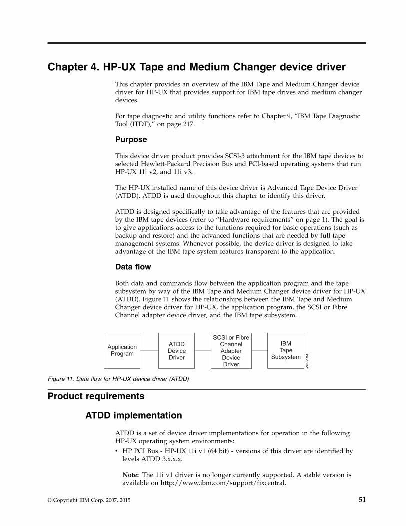
Chapter 4. HP-UX Tape and Medium Changer device driver
This chapter provides an overview of the IBM Tape and Medium Changer devicedriver for HP-UX that provides support for IBM tape drives and medium changerdevices.
For tape diagnostic and utility functions refer to Chapter 9, “IBM Tape DiagnosticTool (ITDT),” on page 217.
Purpose
This device driver product provides SCSI-3 attachment for the IBM tape devices toselected Hewlett-Packard Precision Bus and PCI-based operating systems that runHP-UX 11i v2, and 11i v3.
The HP-UX installed name of this device driver is Advanced Tape Device Driver(ATDD). ATDD is used throughout this chapter to identify this driver.
ATDD is designed specifically to take advantage of the features that are providedby the IBM tape devices (refer to “Hardware requirements” on page 1). The goal isto give applications access to the functions required for basic operations (such asbackup and restore) and the advanced functions that are needed by full tapemanagement systems. Whenever possible, the device driver is designed to takeadvantage of the IBM tape system features transparent to the application.
Data flow
Both data and commands flow between the application program and the tapesubsystem by way of the IBM Tape and Medium Changer device driver for HP-UX(ATDD). Figure 11 shows the relationships between the IBM Tape and MediumChanger device driver for HP-UX, the application program, the SCSI or FibreChannel adapter device driver, and the IBM tape subsystem.
Product requirements
ATDD implementation
ATDD is a set of device driver implementations for operation in the followingHP-UX operating system environments:v HP PCI Bus - HP-UX 11i v1 (64 bit) - versions of this driver are identified by
levels ATDD 3.x.x.x.
Note: The 11i v1 driver is no longer currently supported. A stable version isavailable on http://www.ibm.com/support/fixcentral.
ApplicationProgram
SCSI or FibreChannelAdapterDeviceDriver
ATDDDeviceDriver
IBMTape
Subsystem
a250104
Figure 11. Data flow for HP-UX device driver (ATDD)
© Copyright IBM Corp. 2007, 2015 51

v HP PCI Bus - HP-UX 11i v2 (64-bit for Itanium 2) - versions of this driver areidentified by levels ATDD 5.5.x.x.
v HP PCI Bus - HP-UX 11i v2 (64-bit for PA-RISC) - versions of this driver areidentified by levels ATDD 5.6.x.x.
v HP PCI Bus - HP-UX 11i v3 (64-bit for Itanium 2) - versions of this driver areidentified by levels ATDD IA.6.x.x.x.
v HP PCI Bus - HP-UX 11i v3 (64-bit for PA-RISC) - versions of this driver areidentified by levels ATDD PA.6.x.x.x.
Hardware requirements
For current hardware requirements, refer to the “Hardware requirements” on page1.
Note:
1. ATDD does not support tape devices that are attached to HSC/GSC busarchitectures.
2. For attachment of Enterprise Tape System 3590 and IBM Magstar MP devices toHP rp8400 (formerly V-Class) platforms, a feedthrough SCSI terminator, whichattaches to the A4800A Host Bus Adapter, is required. This feedthrough SCSIterminator is available as FC 9798 for Enterprise Tape System 3590 and FC 5098for the 3575 Tape Library Dataserver or MP 3570 C model tape subsystem.Attach the male end of the feedthrough SCSI terminator to the host adapterand connect the host end of the standard FC 51xx SCSI cable to thefeedthrough terminator. Terminate the SCSI bus at the last device on the bus asusual.
3. The low-level FC-Tape protocol standard is not supported in the HP A5158AHBA firmware and users must restrict their SAN configurations. The jobs areaborted with HP-UX A5158A HBA configurations when errors are detected inthe SAN.The HP A5158A host adapter is not compliant with the Fibre Channel Protocolfor SCSI, second version (FCP-2), dated 17 November 2000, a draft that isproposed by the American National Standard of Accredited StandardsCommittee (NCITS).
4. The HP A6826A HBAs need the QLogic firmware level B.11.11.02 or later. If theadapter is directly connected to a 3592 without a switch, then the topology onthe drive port must be set to L-port.
Software requirements
For current software requirements, refer to the “Software requirements” on page 1.
Attention: To install ATDD in HP-UX 11i v3, some HP-UX patches must beapplied first on the system. For information, refer to the atdd.Readme file that isdownloaded with the driver.
Software interface to the device driver
The IBM Tape and Medium Changer device driver for HP-UX provides thefollowing standard HP-UX entry points for IBM tape systems:
Open This entry point is driven by the open system function call.
Write This entry point is driven by the write system function call.
52 IBM Tape Device Drivers: Installation and User's Guide

Read This entry point is driven by the read system function call.
Close This entry point is driven explicitly by the close system function call andimplicitly by the operating system at program termination.
IOCTLThis entry point is driven by the input/output control (ioctl) systemfunction call. It provides a set of tape device, medium changer device, andSCSI-specific operations. It allows HP-UX applications to access andcontrol the features and attributes of IBM SCSI tape subsystemsprogrammatically.
For programming information, refer to the IBM Tape Device Drivers ProgrammingReference, GA32-0566.
Installation and configuration instructions
The following sections describe the installation and configuration for three types ofHP-UX devices.
Configuration limitations
Maximum supported number of tape devices 1000
Maximum supported number of HBA ports 128
Maximum supported number of paths for adevice (DPF/ CPF)
16/16
Maximum LUNs per system 32
Every attached tape or library device uses a certain amount of resources. The usermust consider resources such as physical memory and virtual space on the system,which can further limit the number of devices that can be attached.
Installing and configuring PCI drivers
This chapter describes how to install, configure, and uninstall the IBM Tape andMedium Changer device driver for HP-UX (ATDD) for PCI-based systems. Bydefault, ATDD automatically configures all supported IBM tape drives that areattached and powered On when the system starts. ACDD, the changer part ofATDD, does not configure IBM Medium Changer devices by default because manyapplications use either their own changer drivers or the native schgr or sctldrivers. In HP-UX 11i v1 and v2, the ATDD package includes with atdd tapedriver and acdd changer driver dynamic loadable kernel modules (DLKM). InHP-UX 11i v3, the ATDD package consists of five modules in the kernel.v atdd - static tape driver kernel modulev acdd - static changer driver kernel modulev atdd_leg - static legacy tape driver kernel modulev acdd_leg - static legacy changer driver kernel modulev atdd_core - DLKM core kernel module
Overview of the installation process
During and after the ATDD is installed, ACDD, the changer part of ATDD, can beset to configure (CLAIM) all attached IBM Medium Changer devices. Additionally,
Chapter 4. HP-UX Tape and Medium Changer device driver 53

selected IBM Medium Changer devices can be configured by running theswinstall command with the -x ask=true command option, or by running/opt/atdd/bin/atdd_claim –c c in 11i v2. The installation process depends onwhether all IBM tape drives are to be configured by ATDD or only selected ones.Also, whether configured tape drives exhibit default behavior or require specificconfiguration settings. Additionally, for IBM Medium Changers, installationselection or post-installation configuration can determine whether all IBM MediumChangers must be configured, selectively configured, or NOT configured at all.
Preinstallation considerations
Make sure that your system is ready to install ATDD before you begin. Followthese steps to complete the installation.1. Copy the software from the distribution medium to the depot.2. Check the readme file and verify that your system is configured appropriately
for installing ATDD.3. Ensure that the tape drives to be managed by ATDD are powered on.4. Install and configure the software.
The following describes facts about the command sequences.v In some of the examples, file names that are given on the command line must be
referenced with an absolute path. Using 'pwd'/filename to reference a fileinstead of filename ensures this.
v All the software distributor commands (for example, swinstall or swcopy) canbe run first with the -p flag to preview the command. After the preview outputis observed, you can reissue the command without the -p flag to complete theactual operation.
v The software distributor commands are moderately complex scripts thatfrequently require several steps. The steps are typically Selection, Analysis, andExecution. Each step can produce useful information and error messages. It is agood idea to carefully observe the results of the installation process as it occurs.
If you encounter unexpected results during the installation, check the associatedlog file.
While the software distributor commands are used, you might encounter thefollowing error about mounted file systems:ERROR: "hostname/": One or more filesystems that appear in thefilesystem table are not mounted and cannot be mounted.
Many commands (for example, swinstall and swremove) attempt to mount all filesystems in the /etc/fstab file at the start of the analysis phase. This action ensuresthat all listed file systems are mounted before proceeding. This action also helpsensure that files are not loaded into a directory that might be below a futuremount point. But, it often causes an error with NFS mounted file systems.
This error can be overridden with '-x' to set the mount_all_filesystems option toFALSE. When this option is used, the command finishes with a warning thatindicates no attempt is made to mount all file systems. For example,# swinstall -x mount_all_filesystems=false -x ask=true -x autoreboot=true atdd
WARNING: "hostname:/": There will be no attempt to mount filesystemsthat appear in the filesystem table.
54 IBM Tape Device Drivers: Installation and User's Guide

Creating the Drive Configuration File (optional)
If you are not using the standard device driver defaults, you must create aconfiguration file that directs the device driver on how to customize driverbehavior for particular IBM devices. If all configured devices are to use the devicedriver configuration defaults, it is not necessary to create a configuration file beforethe driver for ATDD is installed.
The Drive Configuration File is required if you do not use the device driverconfiguration defaults.
If you do not need to create a Drive Configuration File, skip to the instructions in“Powering Off the tape drives” on page 56.
If you do must create a Drive Configuration File, consult the followinginstructions.
The configuration file is named sbin/init.d/atdd and has the following syntax:ATDD_global_parameter=valueATDD_device_parameter[index]=value
Note:
v Blank lines and lines that start with # are ignored.v No spaces can appear within each entry.v No trailing comments can appear on a variable definition line.
Determining the device hardware path for IBM tape drives
To determine the device hardware path for IBM tape drives with a SCSIattachment, complete the following steps.1. Run ioscan to determine the hardware path (the SCSI adapter) the tape drive is
connected to.# ioscan -f -C ext_bus
2. Record the hardware path entry of the adapter:For example: 0/10/0/0
3. Determine the SCSI target address of the tape drive.HWPATH = adapterpath.drivetargetaddress.0 (tape drive)
For a tape drive at SCSI target address 3, the device hardware path is0/10/0/0.3.0
To determine the device hardware path for IBM tape drives with the Fibre Channelattachment, complete the following steps.1. Run ioscan to determine the hardware path (the Fibre Channel) the tape drive
is connected to# ioscan -f -C tape
2. Record the hardware path entry of the Fibre Channel. For example,HWPATH = 0/5/0/0.8.0.255.7.9.0
Chapter 4. HP-UX Tape and Medium Changer device driver 55
Creating the hardware path entry
You must tell the driver which hardware path you want to attach to if you are notusing the installation defaults for driver behavior. Create an entry in the/etc/rc.config.d/atdd configuration file for each device you want the driver toattach. For example:ATDD_HWPATH[0]=0/10/0/0.1.0ATDD_HWPATH[1]=0/10/0/0.6.0ATDD_HWPATH[2]=0/5/0/0.8.0.255.6.14.0
Creating the device-specific configuration entries (optional)
The ATDD is shipped with default settings for all configuration parameters. Tochange these settings, an entry is made in the configuration file that assigns anappropriate value to the wanted configuration variable. Each device can have adifferent value for each configuration variable. The index number that is associatedwith the configuration variable associates the parameter setting with the device atthe hardware path with the same index.
Example 1:ATDD_IMMEDIATE[0]=1
This parameter allows application control to return from the device before therewind completes for the device at hardware path 0/10/0/0.1.0 (based on thehardware path entry in “Creating the hardware path entry”).
Example 2:ATDD_TRAILER[1]=1
This parameter allows write operations after an early end-of-tape warning for thedevice at hardware path 0/10/0/0.6.0. Refer to Table 7 on page 62 and Table 8 onpage 63 for a description of all configuration parameters.
Note: If you experience difficulties with your tape device, check the /etc/rc.log forerrors and correct the problem.
Powering Off the tape drives
When the ATDD software is initially installed, it attaches itself to all tape drivesthat are in the CLAIMED state as shown by entering the command# ioscan -fk -C tape
Before you continue, make sure that all devices CLAIMED with the precedingcommand are devices that you want this device driver to manage.
To list device file names in the /dev directory and its subdirectories, enter# ioscan -funC tape
In HP-UX 11i v3, you can also enter# ioscan -funNC tape
To remove a tape drive from the CLAIMED state so it is not configured by thisdriver, power Off the tape drive and run ioscan without the -k argument asfollows.# ioscan -f -C tape
56 IBM Tape Device Drivers: Installation and User's Guide

Installing the driver with the ATDD installation script
An installation script (InstallAtdd) is provided to automate driver installation andrun some checking functions. It copies the latest version of the driver to thesoftware depot and installs the latest driver version.
To install ATDD with the script, download the installation script with the driver atFix Central, then run the installation script.
When the installation script runs, the customer is prompted with the question,Would you like to activate the Medium Changer support by ATDD (Y/N)?. EnterY to allow the ATDD to configure all attached IBM Medium Changer devices. Or,answer N to allow the HP native changer driver to configure these MediumChanger devices.
Note:
1. If a previous version of ATDD is installed on your system, uninstall it beforeyou attempt to install the latest version. Refer to “Uninstalling the software” onpage 61.
2. The system reboot is required to install ATDD in HP-UX 11i v3.
To install ATDD manually, follow the steps in “Installing drivers manually.”
Installing drivers manually
Installing the drivers manually requires the steps that are detailed in the followingsections.1. “Copying the software to the Software Depot.”2. “Installing the ATDD software.”3. If a previous version of ATDD is installed on your system, uninstall it before
you attempt to install the latest version. Refer to “Uninstalling the software” onpage 61.
Copying the software to the Software Depot
Attention: If you do not copy the ATDD software into a depot, you cannotreadily uninstall the product.
Copy the appropriate driver to the Software Depot. For example:# swcopy -p -s /driver_location/atdd.x.x.x.x atdd (preview option)# swcopy -s /driver_location/atdd.x.x.x.x atdd
Use swlist to verify that the ATDD software is in the depot:# swlist -d atdd
Installing the ATDD software
When the software is in the depot and only the appropriate drives are powered on,the ATDD software can be installed to the root file system with the HP-UXswinstall command. If the target root file system is the primary, the ATDDsoftware is configured automatically upon installation.
If the target is an alternate root file system, then the ATDD software is notconfigured automatically.
Chapter 4. HP-UX Tape and Medium Changer device driver 57

Note: If an earlier version of the product is already installed on the target root filesystem, the existing version is replaced. This replacement is true even if theversion already installed is more recent than the version being installed.
The following commands install ATDD from the depot to the default root filesystem by issuing the swinstall command with the ask options that are set asfollows:# swinstall -p -x ask=true atdd (preview option)# swinstall -x ask=true atdd in HP-UX 11i v1, and v2# swinstall -x autoreboot=true -x ask=true atdd in HP-UX 11i v3
Running the swinstall command with the ask option set to TRUE prompts thecustomer, Would you like to activate the Medium Changer support by ATDD(Y/N)?. Enter Y to allow the ATDD to configure all attached IBM Medium Changerdevices, or answer N to allow the HP native changer driver to configure theseMedium Changer devices.
You can use swlist to list the software that is installed on the default root filesystem as follows:# swlist atdd
You can verify correct installation to the default root file system with the swverifycommand as follows:# swverify atdd
# ioscan -fknC tapeClass I H/W Path Driver S/W State H/W Type Description============================================================================================tape 0 0/3/0/0.5.0 atdd CLAIMED DEVICE IBM 03590E11
/dev/rmt/0m /dev/rmt/0mn /dev/rmt/c4t5d0BEST /dev/rmt/c4t5d0BESTn/dev/rmt/0mb /dev/rmt/0mnb /dev/rmt/c4t5d0BESTb /dev/rmt/c4t5d0BESTnb
tape 1 0/3/0/0.6.0 atdd CLAIMED DEVICE IBM 03590B11/dev/rmt/1m /dev/rmt/1mn /dev/rmt/c4t6d0BEST /dev/rmt/c4t6d0BESTn/dev/rmt/1mb /dev/rmt/1mnb /dev/rmt/c4t6d0BESTb /dev/rmt/c4t6d0BESTnb
tape 4 0/5/0/0.1.23.232.0.0.2 atdd CLAIMED DEVICE IBM ULT3580-TD1/dev/rmt/4m /dev/rmt/4mn /dev/rmt/c6t0d2BEST /dev/rmt/c6t0d2BESTn/dev/rmt/4mb /dev/rmt/4mnb /dev/rmt/c6t0d2BESTb /dev/rmt/c6t0d2BES
If you enabled ACDD, run the following ioscan command to view the mediumchangers found:
# ioscan -fnkC autochClass I H/W Path Driver S/W State H/W Type Description=======================================================================autoch 0 0/3/0/0.5.1 acdd CLAIMED DEVICE IBM 03590E11
/dev/rmt/0chngautoch 2 0/6/0/0.1.17.255.5.10.1 acdd CLAIMED DEVICE IBM 03590E11
/dev/rmt/2chngautoch 4 0/5/0/0.1.23.232.0.0.1 acdd CLAIMED DEVICE IBM ULT3583-TL
/dev/rmt/4chng
In HP-UX 11i v3, run # ioscan -funNC tape or autoch to display the tape devicesthat are configured with ATDD and ACDD drivers. Run # ioscan -funNC tape orautoch to show the tape devices that are bound with the legacy atdd_leg andacdd_leg drivers.
58 IBM Tape Device Drivers: Installation and User's Guide

Configuring all IBM tape drives/Media Changers with ATDD/ACDD
By default, ATDD automatically configures all supported IBM tape drives that areattached and powered on when the ATDD package is installed. The ACDD driverdoes not configure IBM Medium Changer devices by default. To configure all IBMMedium Changer devices on the system during the installation of ATDD package,run the swinstall command with the -x ask=true command option and answerYes to allow the ACDD to claim these devices.v In HP-UX 11i v1 and v2, run the command:
# /opt/atdd/bin/atdd_claim -c
v In HP-UX 11i v3, do the following steps:1. Bind each changer device with the ACDD driver:
# ioscan -b -M acdd -H hw_path
2. Reboot the system to configure the changer devices:# shutdown -ry now
To remove the claim with ACDD after the next reboot:v In HP-UX 11i v1 and v2, run the command:
# /opt/atdd/bin/atdd_claim -u
v In HP-UX 11i v3, do the following steps.1. Bind each changer device with a changer driver. For example, to bind the
changer device with eschgr driver:# ioscan -b -M eschgr -H hw_path
2. Reboot the system to unconfigure the changer devices:# shutdown -ry now
Configuring selected IBM tape devices with ATDD/ACDD in HP-UX 11iv1 and v2
Attaching selected IBM tape devices to ATDD/ACDD during auto booting
To claim a specific tape device with atdd/acdd during reboot, edit the "ClaimingDevice" section in the /sbin/init.d/atdd file.
For example, to attach IBM 3590E11 medium changer with acdd driver:1. To determine the HW path:
# ioscan -fnk|grep IBMautoch 0 0/3/0/0.5.1 schgr CLAIMED DEVICE IBM 03590E11
2. Comment out the command lines in the init script of /sbin/init.d/atdd:v For tape drives:
/opt/atdd/bin/atdd_claim -t
v For medium changers:/opt/atdd/bin/atdd_claim -c
3. Add a command line in the Configuring Device section in /sbin/init.d/atdd:/opt/atdd/bin/atdd_claim -H 0/3/0/0.5.1
Attaching selected IBM tape devices to ATDD/ACDD dynamically
To dynamically attach selected IBM tape device after the ATDD installation, runthe following commands.1. To determine the HW path of the device:
Chapter 4. HP-UX Tape and Medium Changer device driver 59
# ioscan -fnk|grep IBMautoch 0 0/3/0/0.5.1 schgr CLAIMED DEVICE IBM 03590E11
2. To claim the device with ATDD/ACDD:# /opt/atdd/bin/atdd_claim -H 0/3/0/0.5.1
Note: The dynamic attachment might be lost after the system reboots.
Attaching selected IBM tape device with a particular driver
Use the system ioscan and rmsf commands to force a non-atdd/acdd driver tobind an IBM tape device. For example, force bind the IBM 3590E media changerwith the HP native changer driver schgr with these steps:1. Determine the HW path of the device:
# ioscan -fnk |grep IBMtape 0 0/3/0/0.5.0 atdd CLAIMED DEVICE IBM 03590E11autoch 0 0/3/0/0.5.1 acdd CLAIMED DEVICE IBM 03590E11
2. Remove the I/O configuration from the system:# rmsf -H 0/3/0/0.5.1
3. Force binding:# ioscan -M schgr -H 0/3/0/0.5.1
4. Create the device special files:# insf -H 0/3/0/0.5.1
5. Verify the force binding:# ioscan -fnk |grep IBMtape 0 0/3/0/0.5.0 atdd CLAIMED DEVICE IBM 03590E11autoch 0 0/3/0/0.5.1 schgr CLAIMED DEVICE IBM 03590E11
Note: The force binding is lost after the system reboots. To keep the binding toa selected device with a particular driver after a reboot, add thesecommand-lines in steps 2–4 in Claiming Device section in /sbin/init.d/atdd file.For example,# Configuring Device Section:# add specific device claim here, for example# /opt/atdd/bin/atdd_claim -H 0/3/0/0.5.1# /opt/atdd/bin/atdd_claim -H 0/6/0/0.1.30.255.0.0.1rmsf -H 0/3/0/0.5.1ioscan -M schgr -H 0/3/0/0.5.1insf -H 0/3/0/0.5.1
Configuring selected IBM tape devices with ATDD/ACDD in HP-UX 11iv3
By default, atdd driver automatically configures all supported IBM tape drives thatare attached and powered on when the ATDD package is installed. The acdddriver does not configure IBM medium changer devices by default. All of IBMmedium changers are claimed if you use acdd and acdd_leg as the changer driversduring ATDD are installed. To attach a selected IBM tape device with a particulardriver, run the system ioscan command to force a non-ATDD/ACDD driver tobind an IBM tape device, and then reboot the system. For example, to force bindthe IBM 3592 E05 tape drive with the HP native tape driver estape, complete thesesteps:1. Determine the HW path of the device:
# ioscan -fNk | grep IBMtape 1 64000/0xfa00/0x7 atdd CLAIMED DEVICE IBM 03592E05
2. Force the binding:
60 IBM Tape Device Drivers: Installation and User's Guide

# ioscan -b -M estape -H 64000/0xfa00/0x7
3. Reboot the system:# shutdown -ry now
4. Create the device special files if it does not exist after the system bootup:# insf -H 64000/0xfa00/0x7
5. Verify the force binding:# ioscan -fNk | grep IBMtape 1 64000/0xfa00/0x7 estape CLAIMED DEVICE IBM 03592E05
Uninstalling the software
Attention: Do not try to uninstall the ATDD software by deleting the files thatmake up the ATDD file set. This action causes a number of inconsistencies on thesystem. It is best to use the swremove command.
To uninstall ATDD (from the root file system):# swremove atdd in HP-UX 11i v1 and v2# swremove -x autoreboot=true atdd in HP-UX 11i v3
Other administrative tasks
To determine whether the current version of ATDD is installed or configured onthe default root file system:# swlist -a state atdd
To determine the versions of ATDD stored in the default depot:# swlist -d atdd
To remove ATDD from the depot:# swremove -d atdd
If more than one level of ATDD exists in the depot, explicitly specify the level toremove it. For example:# swremove -d atdd,r=3.5.0.0
To view the file set of ATDD installed on the system:# swlist -l file atdd
To display and manage ATDD kernel modules and kernel-tunable parameters, runkmadmin, kmsystem, kmtute, and kmadmin commands in HP-UX 11i v1 and kcmodule,kctune commands in HP-UX 11i v2 and v3, or go to the Kernel Configuration inthe sam utility. Refer to the system manual for detail.
For an example, print the ATDD driver module status, entering the command:# kcmodule -d atddModule State Cause Descriptionatdd static explicit Advanced Tape Device Driver
Supported configuration parameters
This chapter describes the supported configuration values for multiple device typesthat are configured on the same system. The configuration parameters are global.Because the configuration parameters are global to all devices, it is necessary touse configuration values that run reliably on all devices that are attached to your
Chapter 4. HP-UX Tape and Medium Changer device driver 61

system. If you are experiencing difficulties, ensure that your driver is configuredproperly. To check your current configuration, use the atdd_cfg program that is in/opt/OMImag/bin for the static PB driver and in /opt/atdd/bin for the PCI driver.For program usage, run as follows:
For PB driver:# /opt/OMImag/bin/atdd_cfg -h
For PCI driver:# /opt/atdd/bin/atdd_cfg -h
Configuration parameter definitions
This section describes the configuration parameters and values. Modifying thedefault settings is not recommended unless instructed to do so. The ATDD isshipped with default values that allow the most reliable execution across variousdevice types.
Device-specific parameters
Some of the configuration parameters are device-specific, while others aredriver-specific. Table 7 shows the parameters that are device-specific, what theymean, and their values.
Table 7. HP-UX: Device-specific parameter definitions
Parameter Meaning Values
DENSITY Density to use whenwriting/reading tape
In hexadecimal
SILI Suppress Incorrect LengthIndicator
v 0=Off (do not suppress, bydefault)
v 1=On (suppress)
BLOCKSIZE Block Size Size in bytes, 0 by default.
COMPRESSION Compression Mode v 0=Off (do not use compressionat drive)
v 1=On (use compression atdrive, by default)
BUFFERING Buffering Mode v 0=Off (do not buffer data)
v 1=On (buffer data to hardwarebuffers, by default)
IMMEDIATE Immediate Mode v 0=Off (wait for rewindcompletion, by default)
v 1=On (return before rewind iscomplete)
TRAILER Trailer Label Processing v 0=Off (do not allow writes pastearly EOT warning, by default)
v 1=On (allow writes past earlyEOT warning)
ERRNO_LEOT Error Number return forLogical End Of Tape)
Value that is returned for writespast EOM, 28 by default.
62 IBM Tape Device Drivers: Installation and User's Guide

Table 7. HP-UX: Device-specific parameter definitions (continued)
Parameter Meaning Values
RESERVE Multiple open for thedevice
v 1=On (reserve the device afterto open, by default)
v 0=Off (do not reserve thedevice after to open) (multipleopen support)
RESERVE_KEY The user specifies thePersistent Reservationkey that is used by thedevice driver when thePersistent Reservation isused.
v 0 (the driver assigns the key bydefault)
v A string of 1-8 character ASCIIalphanumeric key such as"key12345". If fewer than 8characters are used, theremaining characters are set to0x00(NULL)
WFM_IMMEDIATE Immediate Mode forWrite File Mark
v 0=Off (wait for write file markcompletion, by default)
v 1=On (return before write filemark is complete)
PRE_V3_COMPAT Use to share tapes withblocksize > 256 kb withHP-UX 11i v2 or earlier.Supported in HP-UX 11iv3 only.
v 0=Off (always write or read thedate with the blocksize definedby user, by default)
v 1=On (split the blocksize lessthan 256 kb during the read orwrite)
Driver-specific parameters
Some of the configuration parameters are device-specific, while others aredriver-specific.Table 8 shows the parameters that are driver-specific, what theymean, and their values.
Table 8. HP-UX: Driver-specific parameters (Global)
Parameter Meaning Values
INSTANCE ATDD Device Number (Read Only)
DEVICES Number of Configured Devices (Read Only)
Modifying configuration parameters
To change a configuration parameter, use the atdd_cfg program in/opt/OMImag/bin for the PB driver and in /opt/atdd/bin for the PCI driver. Youcan update the current value.v In HP-UX 11i v1 and v2:
For example, if you want to change the COMPRESSION parameter to 0 for thedevice at hardware path 0/4/0/0.1.0, do the following step:# atdd_cfg -g INSTANCE 0/4/0/0.1.0INSTANCE: 2
The ATDD instance number for this device is returned. You must use thisINSTANCE value (1) to set the COMPRESSION value for this device.# atdd_cfg -s COMPRESSION 0 2
Or, to get or modify COMPRESSION by using the hardware path:
Chapter 4. HP-UX Tape and Medium Changer device driver 63

# atdd_cfg -g COMPRESSION 0/4/0/0.1.0# atdd_cfg -s COMPRESSION 0 0/4/0/0.1.0
v In HP-UX 11i v3:The usage of atdd_cfg command is:atdd_cfg -d special_file [-o parameter [-w value]]
All configurable parameters for the specified device are displayed by entering#atdd_cfg -d special_file only
For instance:# /opt/atdd/bin/atdd_cfg -d /dev/rtape/tape14_BESTDENSITY=0SILI=1BLOCKSIZE=0COMPRESSION=1BUFFERING=1REWIND_IMMEDIATE=0TRAILER=1SCALING=0WRITEPROTECT=0ERRNO_LEOT=28WFM_IMMEDIATE=0RESERVE=1PRE_V3_COMPAT=0
To display a specific parameter, run #atdd_cfg -d special_file -o parameterFor example,#/opt/atdd/bin/atdd_cfg -d /dev/tape/tape14_BESTn -o COMPRESSIONCOMPRESSION=1
To set a specific parameter, run #atdd_cfg -d special_file -o parameter -wvalue
For example,# atdd_cfg -d /dev/rtape/tape14_BESTn -o COMPRESSION -w 0Success
To set a new BOOT default value for the configuration parameter, you mustmodify or add an entry in the atdd.cfg configuration file in /etc/rc.config.d forthe static driver or the atdd configuration file in /sbin/init.d.
For example, if you want the COMPRESSION default set to 0 for the device atATDD_HWPATH[0] or tape14_BESTn, add the following line to your configuration file:v In HP-UX 11i v1 and v2:
ATDD_COMPRESSION[0]=0
v In HP-UX 11i v3:/opt/atdd/bin/atdd_cfg -d /dev/rtape/tape14_BESTn -o COMPRESSION -w 0
Note: The configuration parameters are prefixed with ATDD_ in the configurationfile. For instructions about using the configuration program, use the -h option asfollows:# atdd_cfg -h
Configurable kernel parameters (tunable)
ATDD provides the following variety of configurable kernel parameters that allowthe users to customize for specific setup:
64 IBM Tape Device Drivers: Installation and User's Guide

atdd_log_traceLog the sense data in syslog when a hardware or medium error isoccurred, see “Sense data logging” on page 72 for details. This parameteris enabled by default on 11i v3 and later, but disabled by default in 11i v2and earlier.
alternate_pathing/atdd_alternate_pathingEnable or disable the alternate path support for CPF/DPF (see the specificoperating system section that covers CPF and DPF support for detail). Thisparameter is enabled by default.
atdd_disable_reserve/atdd_disable_resAllows the user to disable the reservation management from ATDD. Thisparameter is Off by default.
atdd_loadbalanceAllows the user to disable automatic load balancing from ATDD. Thisparameter is On (1) by default and supported on 11i v3 only.
atdd_reserve_typeThe drive is reserved in the SCSI-2 Reserve command when Data Pathfailover (DPF) is disabled by default. To reserve the drive with PersistentReserve In and Out commands, the user can set the value ofatdd_reserve_type to 3. The default values for the tunable:v 1 - Reserve(6) command.v 2 - Reserve(10) command (Unsupported).v 3 - Persistent Reserve In/Out commands.
To change the value of tunable, run the command kctune/kmtune or the SAM(System Administration Manager) tool.
Special files
For each drive configured by ATDD, 12 or 13 special files are created. 12 specialfiles are generated for a 3590 with ACF set to Manual, Automatic, System,Accumulate, Random, or Library mode. A 13th special file is created forindependent operation of the ACF, if the 3590 mode is set to Random 2 LUNoperation (/dev/rmt/<instance#>chng).
ATDD creates the tape device special files in three forms -v The standard or long file name.v An alternative short file name that is based on the instance number.v An alternative short file name that is not based on the instance number.
BEST represents the operational capabilities likely to be required, including thehighest density/format and data compression, if supported by the device. Each setof special file names (long and short) contains four special files that have allcombinations of n and b options, as shown in Table 9 and Table 10 on page 66. Forinformation, refer to the mt(7) man pages.
Table 9. Special files
Special file nameBSD
compatibilityRewind on
close
/dev/rmt/<instance#>m No Yes
/dev/rmt/<instance#>mb Yes Yes
Chapter 4. HP-UX Tape and Medium Changer device driver 65

Table 9. Special files (continued)
Special file nameBSD
compatibilityRewind on
close
/dev/rmt/<instance#>mn No No
/dev/rmt/<instance#>mnb Yes No
/dev/rmt/s<#>m No Yes
/dev/rmt/s<#>mb Yes Yes
/dev/rmt/s<#>mn No No
/dev/rmt/s<#>mnb Yes No
/dev/rmt/<instance#>t<target>d<LUN>BEST No Yes
/dev/rmt/<instance#>t<target>d<LUN>BESTb Yes Yes
/dev/rmt/<instance#>t<target>d<LUN>BESTn No No
/dev/rmt/<instance#>t<target>d<LUN>BESTnb Yes No
/dev/rmt/<instance#>chng N/A N/A
Table 10. New special files in HP-UX 11i v3
Special file nameBSD
compatibilityRewind on
close
/dev/rtape/tape#_BEST No Yes
/dev/rtape/tape#_BESTb Yes Yes
/dev/rtape/tape#_BESTn No No
/dev/rtape/tape#_BESTnb Yes No
/dev/rchgr/autoch# N/A N/A
v In HP-UX 11i v1 and v2:atdd_lssf in /opt/OMImag/bin for the static driver and in /opt/atdd/bin for theDLKM driver lists information about a special file. For example,#atdd_lssf /dev/rmt/393mnbatdd card instance 30 available at address Major = 79 Minor = Ox1E90C0settings = No Rewind, Berkeley, Best Format,IBM 03590H1A /dev/rmt/393mnb
v In HP-UX 11i v3:ATDD supports the HP-UX lssf, insf, and rmsf commands. To display specialfile information, enter the lssf command. For example,# lssf /dev/rtape/tape14_BESTnbatdd Berkeley No-Rewind best density available at address 64000/0xfa00/0x32/dev/rtape/tape14_BESTnb
# lssf /dev/rchgr/autoch1acdd section 0 at address 64000/0xfa00/0x21 /dev/rchgr/autoch1
If the device special files are not created on the system, use the # insf commandto generate them.
66 IBM Tape Device Drivers: Installation and User's Guide

Persistent Naming Support
Persistent Naming Support is used to ensure that attached devices are alwaysconfigured with the same logical name across system reboots. For this purpose, theHP-UX tape driver creates an extra set of device special files with a prefix of "s" forthe configured tape drives in HP-UX 11i v1 and v2, such as s55m in the followingexample.# ioscan -funC tapeClass I H/W Path Driver S/W State H/W Type Description===================================================================================tape 103 1/0/0/0.97.25.255.2.7.0 atdd CLAIMED DEVICE IBM 03592E05
/dev/rmt/103m /dev/rmt/c10t7d0BESTn /dev/rmt/s55mb/dev/rmt/103mb /dev/rmt/c10t7d0BEST /dev/rmt/s55mn/dev/rmt/103mn /dev/rmt/c10t7d0BESTb /dev/rmt/s55m/dev/rmt/103mnb /dev/rmt/c10t7d0BESTnb /dev/rmt/s55mnb
In HP-UX 11i v3, HP introduces the native multi-pathing and path-independentpersistent Device Special Files (DSFs) and the auto discovery of devices to enhanceoverall manageability. The ATDD does not create the additional set of devicespecial files with a prefix of “s”.
The persistent DSF format for tape devices that are introduced with the Agile viewin HP-UX 11i v3 is# ioscan -funNC tapeClass I H/W Path Driver S/W State H/W Type Description===================================================================tape 1 64000/0xfa00/0x7 estape CLAIMED DEVICE IBM 03592E05
/dev/rtape/tape1_BEST /dev/rtape/tape1_BESTn/dev/rtape/tape1_BESTb /dev/rtape/tape1_BESTnb
# ioscan -funNC autochClass I H/W Path Driver S/W State H/W Type Description=================================================================autoch 8 64000/0xfa00/0xa acdd CLAIMED DEVICE IBM 03584L22
/dev/rchgr/autoch8
To map a persistent DSF to its legacy DSF, enter the following -# ioscan -m dsf /dev/rtape/tape1_BESTbPersistent DSF Legacy DSF(s)========================================/dev/rtape/tape1_BESTb /dev/rmt/c3t15d0BESTb
/dev/rmt/c9t6d0BESTb
Control Path failover support for tape libraries
Note:
1. The library control path failover feature code must be installed before the pathfailover support is enabled in the HP-UX ATDD device driver. Referto“Automatic failover” on page 5 for what feature code might be required foryour machine type.
2. It is a requirement that applications must open the primary path for CPF.
Configuring and unconfiguring path failover support
Path failover support is enabled automatically when the device driver is installed.However, the driver provides a kernel parameter that you can use to enable library
Chapter 4. HP-UX Tape and Medium Changer device driver 67

control path failover. To enable the failover support in the ATDD driver, completethe following steps after the driver is installed.v In HP-UX 11i v1 and v2:
1. Set the alternate_pathing parameter.# /opt/atdd/bin/atdd_failover -a 1
2. Reconfigure CPF for the devices.# /opt/atdd/bin/atdd_claim
v In HP-UX 11i v3:Run kctune to enable the kernel tunable of atdd_alternate_pathing. ATDDhandles the CPF in the next open.# kctune atdd_alternate_pathing=1
* The automatic ’backup’ configuration has been updated.* The requested changes have been applied to the currently
running configuration.Tunable Value Expression Changesatdd_alternate_pathing (before) 0 0 Immed
(now) 1 1
You can check whether the driver recognized multiple control paths for yourlibrary by running#ioscan -funC autoch
If you see .altpath next to one of the special files in HP-UX 11i v1 and v2, thenyou successfully enabled the control path failover feature for your library. InHP-UX 11i v3, use the # ioscan -m dsf command and “[11] Display All Paths” onpage 256 or “Display All Paths” on page 317 in ITDT to verify that the multiplepath is configured by the system and ATDD.
After the path failover support is enabled, it remains set until atdd_claim is runwith the alternate_pathing driver parameter set to OFF. The path failover settingis retained even if the system is rebooted. If you want to turn off the control pathfailover feature in the ATDD driver, complete the following steps.v In HP-UX 11i v1 and v2:
1. Clear the alternate_pathing parameter.# /opt/atdd/bin/atdd_failover -a 0
2. Reconfigure CPF for the devices.# /opt/atdd/bin/atdd_claim
v In HP-UX 11i v3:Run kctune to disable the kernel tunable of atdd_alternate_pathing. ATDDmanages the CPF in the next open.# kctune atdd_alternate_pathing=0
* The automatic ’backup’ configuration has been updated.* The requested changes have been applied to the currently
running configuration.Tunable Value Expression Changesatdd_alternate_pathing (before) 1 1 Immed
(now) 0 0
Primary and alternative paths
When ATDD is loaded into the kernel, the first logical medium changer device thatit sees in the system is the primary path for that medium changer. The otherlogical medium changers that ATDD attached for the same medium changer isconfigured as alternative paths. The device driver supports up to 16 physical pathsfor a single device.
68 IBM Tape Device Drivers: Installation and User's Guide

On HP-UX 11i v3, the HP-UX system always selects the best path for ATDD toopen so the primary path is dynamically assigned from the system. ATDD doesnot provide any .altpath special file.
The primary and alternative path information can be obtained by using thefollowing command on HP-UX 11i v1 and v2.# ioscan -funC autoch
The following is an example of what you might see:
autoch 0 0/1/0/0.101.22.255.1.1.1 acdd CLAIMED DEVICE IBM ULT3582-TL /dev/rmt/0chngautoch 1 0/1/0/0.101.22.255.1.2.1 acdd CLAIMED DEVICE IBM ULT3582-TL /dev/rmt/1chng.altpath
Querying primary and alternative path configurations
You can display the primary and alternative path configuration for all devices byrunning the ioscan command, as explained in “Determining the device hardwarepath for IBM tape drives” on page 55.
Note: To display the primary and alternative path configuration for any device byusing tape diagnostic and utility functions, refer to Chapter 9, “IBM TapeDiagnostic Tool (ITDT),” on page 217.
Disabling and enabling primary and alternative paths
When you load the ATDD device driver with the alternate_pathing parameter setto ON, by default, all the available paths for a physical device are enabled.
If it is necessary to disable a path and not complete path failover (for example dueto maintenance), run commands to disable and then later enable the primary andalternative paths.
The commands to enable and disable primary and alternative paths are tapediagnostic and utility functions.
Note: See Chapter 9, “IBM Tape Diagnostic Tool (ITDT),” on page 217.
Data Path failover and load balancing support for tape drives
The HP-UX device driver path failover support configures multiple physical pathsto the same device within the device driver and provides two basic functions.1. Automatic failover to an alternative physical path when a permanent error
occurs on one path.2. Dynamic load balancing for devices with multiple Host Bus adapters (HBA).
On HP-UX 11i v3, HP-UX system always picks up a best path for ATDD toopen. ATDD does not run a dynamic load balancing in open.
Note:
1. Data Path failover is not supported when block sizes greater than 256 K areused, except in HP-UX 11i v3.
2. It is required that applications must open the primary path for Data Pathfailover (not in HP-UX 11i v3).
Chapter 4. HP-UX Tape and Medium Changer device driver 69

3. Data Path failover is supported for 3592 tape drives on HP-UX 11i v2 and v3,and for Ultrium 3, Ultrium 4, Ultrium 5, and Ultrium 6 drives on HP-UX v2and v3.
Configuring and unconfiguring path failover support
Path failover support is turned on automatically when the device driver isinstalled. However, you must provide the data path failover feature key andreclaim the devices by using the atdd_claim script. The feature key is a string with16 characters and numbers.1. Edit the following line in your /sbin/init.d/atdd file.
DPF_KEYS="1234567890123456; 0987654321123456 "
Note:
a. 1234567890123456 is an example of a data path failover feature key. If youhave multiple 3584 libraries and multiple data path failover feature keys,input your keys as follows:DPF_KEYS="key1; key2; ..."
b. A DPF key is required for Ultrium 3 tape drives only. No DPF key must beadded into the /sbin/init.d/atdd file if you are running the most recent drivecode.
2. Save the file, then run the following command in HP-UX 11i v1 and v2:# /opt/atdd/bin/atdd_claim
3. In HP-UX 11i v1 and v2, you can check whether the driver recognized multipledata paths for your drives by running:#ioscan -funC tape
If you see ".altpath" next to one of the special files, then you successfullyenabled control path failover feature for your library.
In HP-UX 11i v3, use the # ioscan -m dsf command to verify that the multiple pathis configured by the system and ATDD.
Note: See Chapter 9, “IBM Tape Diagnostic Tool (ITDT),” on page 217.
After path failover support is enabled, it remains set until atdd_claim or kctune isrun with the alternate_pathing driver parameter set to OFF. The path failoversetting is retained even if the system is rebooted. If you want to turn off the datapath failover feature in the ATDD driver, complete the following steps.
In HP-UX 11i v1 and v2:1. Clear the alternate_pathing parameter. (You can ignore the message about
rebooting the system.)# /opt/atdd/bin/atdd_failover -a 0
2. Reconfigure DPF for the devices.# /opt/atdd/bin/atdd_claim
In HP-UX 11i v3:
Run kctune to disable the kernel tunable of atdd_alternate_pathing. ATDD handlesthe DPF in the next open.
70 IBM Tape Device Drivers: Installation and User's Guide

# kctune atdd_alternate_pathing=0* The automatic ’backup’ configuration has been updated.* The requested changes have been applied to the currently
running configuration.Tunable Value Expression Changesatdd_alternate_pathing (before) 1 1 Immed
(now) 0 0
If you want to turn the data path failover feature back on in the ATDD driver,complete the following steps.
In HP-UX 11i v1 and v2:1. Set the alternate_pathing parameter. (You can ignore the message about
rebooting the system.)# /opt/atdd/bin/atdd_failover -a 1
2. Reconfigure DPF for the devices.# /opt/atdd/bin/atdd_claim
In HP-UX 11i v3:
Run kctune to enable the kernel tunable of atdd_alternate_pathing. ATDD handlesthe DPF in the next open.# kctune atdd_alternate_pathing=1
* The automatic ’backup’ configuration has been updated.* The requested changes have been applied to the currently
running configuration.Tunable Value Expression Changesatdd_alternate_pathing (before) 0 0 Immed
(now) 1 1
Primary and alternative paths
When ATDD is loaded into the kernel, the first logical device that it sees in thesystem is the primary path for that medium changer. The other logical paths thatATDD attached for the same tape drive is configured as alternative paths. Thedevice driver supports up to 16 physical paths for a single device. In HP-UX 11iv3, the HP-UX system always picks up the best path for ATDD to open so theprimary path is dynamically assigned from the system. ATDD does not provideany .altpath special file.
The primary and alternative path information can be obtained by issuing thefollowing command except in HP-UX 11i v3.# ioscan -funC tape
The following is an example of the output for this command.home/root# ioscan -funC tapeClass I H/W Path Driver S/W State H/W Type Description===============================================================================tape 0 0/1/0/0.101.22.255.1.1.1 atdd CLAIMED DEVICE IBM ULT3580-TD3 /dev/rmt/0mtape 1 0/1/0/0.101.22.255.1.2.1 atdd CLAIMED DEVICE IBM ULT3580-TD3 /dev/rmt/1m.altpath
Querying primary and alternative path configuration
You can display the primary and alternative path configuration for all devices byrunning ioscan, as explained in “Primary and alternative paths.”
Chapter 4. HP-UX Tape and Medium Changer device driver 71

Note: To display the primary and alternative path configuration for any device byusing tape diagnostic and utility functions, refer to Chapter 9, “IBM TapeDiagnostic Tool (ITDT),” on page 217.
Disabling and enabling primary and alternative paths
If it is necessary to disable a path and not complete path failover (for example dueto maintenance), run commands to disable and then later enable the primary andalternative paths.
The commands to enable and disable primary and alternative paths are tapediagnostic and utility functions.
Note: See Chapter 9, “IBM Tape Diagnostic Tool (ITDT),” on page 217.
Problem determination
A set of tools is provided with the device driver to determine if the device driverand the tape device are functioning correctly.
Error logging
Read the system log file (typically /var/adm/syslog/syslog.log) and the ATDD logfile (/var/adm/atdd/atdd_d.log) if you are having problems. The ATDD logsmessages to this file that provides information about the problem.
Sense data logging
When the tape drive responds with CHECK CONDITION status and associatedsense keys of 0x1 (Recovery Error), 0x3 (Medium Error), 0x4 (Hardware Error), and0xB (Aborted Command) for a hardware or medium error, the sense data is loggedin to the system log file (typically /var/adm/syslog/syslog.log). The sense datalogging feature is disabled by default on 11i v1 and 11i v2 and enabled by defaulton 11i v3. To enable the support dynamically, run /opt/atdd/bin/atdd_cfg with the-c option.# /opt/atdd/bin/atdd_cfg -c 1
* The requested changes have been applied to the currently running system.Tunable Value Expression Changesatdd_log_trace (before) 0 Default Immed
(now) 1 1
Support_info script
Run the support_info script, in the /opt/OMImag/bin directory for the static driverand in /opt/atdd/bin for the DLKM driver. This script gathers important systemand configuration information. There are several sections with the keywordVERIFY, indicating information that must be verified for correctness.
Log in as user ID "root" on the system that experienced a problem. Then, run thescript and redirect the output to an end of a file.
Static/opt/OMImag/bin/support_info > support_info.out
72 IBM Tape Device Drivers: Installation and User's Guide

DLKM/opt/atdd/bin/support_info > support_info.out
Tracing facility
Running the ATDD_trace utility, in the /opt/OMImag/bin for the static driver and in/opt/atdd/bin for the DLKM driver, displays debug information. The utility tracescan be started at any time before an operation on a tape device. The default debuglevel is 0x00001003, which shows driver configuration and per instance driveattribute configuration and errors. You can increase the amount of debuginformation that is displayed by enabling more trace flags. Issuing atdd_trace -f0x1fffffff turns on every trace.1. Determine which items must be traced and set the trace flags by using the
atdd_trace command. For example, to trace everything -For the Static driver:/opt/OMImag/bin/atdd_trace -f 0x1fffffffFor the DLKM driver:/opt/atdd/bin/atdd_trace -f 0x1fffffffIn HP-UX 11i v3, run the sam utility or # kctune atdd_trace_level=1command to set the trace level to 1. The default set is 3. The different levelsof tracing for 11iv3 are
v Full trace = 1v Messages = 2v Warnings = 3v Errors = 4The set of trace flags is displayed in Table 11.
Table 11. Trace flags
COMMAND VALUE
Configuration 0x00000001
General errors 0x00000002
Routine entry points 0x00000004
Returns 0x00000008
TRACE_DBG information 0x00000010
Open/Close routine 0x00000020
Trace motion commands 0x00000040
Read/Write 0x00000100
Strategy 0x00000200
Open/Close states 0x00000400
IOCTLs 0x00000800
Trace device config routines 0x00001000
Trace SCSI level stuff 0x00004000
Configuration 0x10000000
Entry point 0x01000000
General information 0x00400000
Memory 0x00200000
2. Clear the trace buffer.For the Static driver:/opt/OMImag/bin/atdd_trace -c
Chapter 4. HP-UX Tape and Medium Changer device driver 73

For the DLKM driver:/opt/atdd/bin/atdd_trace -c3. To have trace data that is displayed immediately in a readable format as it is
collected.For the Static driver:/opt/OMImag/bin/atdd_trace -bFor the DLKM driver:/opt/atdd/bin/atdd_trace -b
4. Start the operations on a tape device.5. To display collected trace data in a readable format at any time:
For the Static driver:/opt/OMImag/bin/atdd_trace -dFor the DLKM driver:/opt/atdd/bin/atdd_trace -d
6. The atdd_trace output can be redirected to place the trace data in a readableformat into a file, by enteringFor the PB driver:/opt/OMImag/bin/atdd_trace >trace.txtFor the PCI driver:/opt/atdd/bin/atdd_trace >trace.txt
7. In HP-UX 11i v3, the ATDD trace is logged in to syslog of /var/adm/syslog/syslog.log when the kernel tunable of atdd_direct_trace is enabled. To set avalue (0 or 1) to atdd_direct_trace, run # kctune atdd_direct_trace=value. Toturn on the trace #kctune atdd_direct_trace=1 and set to 0 to turn off.
Problems and solutions
Table 12 describes problems and possible solutions for errors you might encounterwith the DLKM driver.
Table 12. Problems, reasons, and solutions
Problem Reason and solution
The system hangs when it runs rmsf -H on HP-UX 11i. DLKM Infrastructure does not set the correct flag in thedevice switch table entry for a DLKM driver that uses.
Install HP patch PHKL_29818.
ATDD DLKM modules are not loaded in the runningkernel.A message in the file /var/adm/syslog/syslog.log
"vmunix: WARNING: modpath: DLKM is not initialized"
The current kernel is not matching the symbol table(DLKM) in /stand/dlkm
Must rebuild the kernel by running the followingcommands:
#cd /stand/build#/usr/lbin/sysadm/system_prep -s /stand/build/system#/usr/sbin/mk_kernel -s /stand/build/system#mv /stand/system /stand/system.prev#mv /stand/build/system /stand/system#kmupdate /stand/build/vmunix_test#shutdown -ry now
A message in the file /var/adm/syslog/syslog.log
"modld: Attempt to load unregistered module "
ATDD DLKM Module's component files are not copiedto certain subdirectories of /usr/conf and /stand.
Remove ATDD and try to install it again.
# kmtune | grep atdd
kmtune: Cannot open file -- /stand/.kmsystune_lock
The file .kmsystune_lock was removed manually.
Use the following command to create the.kmsystune_lock file again:
# touch /stand/.kmsystune_lock
74 IBM Tape Device Drivers: Installation and User's Guide

Table 12. Problems, reasons, and solutions (continued)
Problem Reason and solution
IBM tape devices not claimed in ioscan -fnk display As "root", verify the drivers that are loaded in therunning kernel by using `kmadmin -s`.
If status is "LOADED", run 'atdd_claim -b' to claim allIBM devices, run 'atdd_claim -t' to claim the tapedrives, then run 'atdd_claim -c' to claim the changers.
If status is "UNLOADED", run 'kmadmin -L atdd' toload the ATDD, run 'kmadmin -L acdd' to load theACDD, then run 'atdd_claim' to claim the tape devices.
If status is still "UNLOADED", check the entries of thefiles 'atdd' or 'acdd' in /etc/loadmods. If no atdd or acddfile entries exist, the driver might be statically bound tothe kernel, or the ATDD package might not be installed.Check the installation by running the followingcommand:
# swlist atdd
No special files that are found in /dev/rmt Run the atdd_mksf and acdd (if you have changers thatare managed by the acdd driver) scripts that are foundin /opt/atdd/bin
atdd_mksf and acdd_mksf
Note: The script prints the commands that are necessaryto create the special files. To create the files you must"pipe" the output to shell (sh), with the followingcommands:atdd_mksf | sh acdd_mksf | sh.
The special files for a device are duplicates. Remove all of the special files for the device in /dev/rmt
Create the special files again by running the commandsatdd_mksf or acdd_mksf.
No special files are created by HP Stape and Schgr afterATDD is installed
Create the special files by running the command: # insf-e.
Cannot open Special File and the system log has thefollowing message:
Invalid SCSI request in data at bit 7 of byte 4
Wrong DENSITY setting. Check the current value byrunning the command:atdd_cfg -g DENSITY Try settingvalue to 0 (zero) by running the command: atdd_cfg -sDENSITY 0.
An attempt to read data times out and returns an errorand the system log has the following messages:
A SCSI command timed out and was aborted.
Make sure that the SILI configuration parameter is "1".This configuration can be checked by running thecommand: atdd_cfg -g SILI
If the value of SILI = 0, try setting the value to 1, byrunning the following command: atdd_cfg -s SILI 1.
Table 13 describes problems and possible solutions for errors you might encounterwith the static driver.
Table 13. Troubleshooting (problems and solutions)
Problem Solution
No special files that are found in /dev/rmt Issue the following commands: /opt/OMImag/bincd/opt/OMImag/binatdd_mksf | sh.
Chapter 4. HP-UX Tape and Medium Changer device driver 75

Table 13. Troubleshooting (problems and solutions) (continued)
Problem Solution
If you are using the PB drivers or are not using thestandard device driver defaults with PCI drivers:
Verify that the hardware path for the device is listed inthe configuration file/etc/rc.config.d/atdd.cfg
If the hardware path is missing or incorrect, the driverwas not installed properly.
Claimed by HP Stape driver Run the command: # lsdev to check that the atdd is inthe current kernel.
1. If the atdd is not in the output, rebuild the kernel orreinstall atdd.
2. If the atdd is in the output -
a. Rebuild the system I/O configuration.
1) Remove /stand/ioconfig and /etc/ioconfigafter to back up the files.
2) Reboot the system.
3) On System Console, enter the command #/sbin/ioinit -c while the autobooting ishalted.
4) Run the command: # /sbin/insf -e.
5) Enter the command: # ̂ D to exit the I/Oconfiguration.
b. Reinstall the HP-UX operating system if thesystem is new or is a new update.
Cannot open Special File. The system log has thefollowing message:
Invalid SCSI request in data at bit 7 of byte 4
Wrong DENSITY setting. Check the current value by:
atdd_cfg -g DENSITY <atdd_inst>
Try setting it to 0 (zero):
atdd_cfg -s DENSITY 0 <atdd_inst>
An attempt to read data times out and returns an error.The system log has the following messages:
A SCSI command timed out and was aborted.
LLIO: Detected PowerFail(probably caused by SCSI bus or device reset).
Check that the SILI configuration parameter is 1 byrunning
atdd_cfg -g SILI <atdd_inst>
If the SILI parameter is zero, try setting it to 1:
atdd_cfg -s SILI 1 <atdd_inst>
An attempt to read data times out and returns an error.The system log has the following messages:
A SCSI command timed out and was aborted.
scsi3: ....date code...
scsi3: ....timestamp...
Check that the FORCE_NARROW parameter is valid forthis device by running
atdd_cfg -g FORCE_NARROW <atdd_inst>
If FORCE_NARROW is 1, try setting it to 0:
atdd_cfg -s FORCE_NARROW 0 <atdd_inst>
76 IBM Tape Device Drivers: Installation and User's Guide
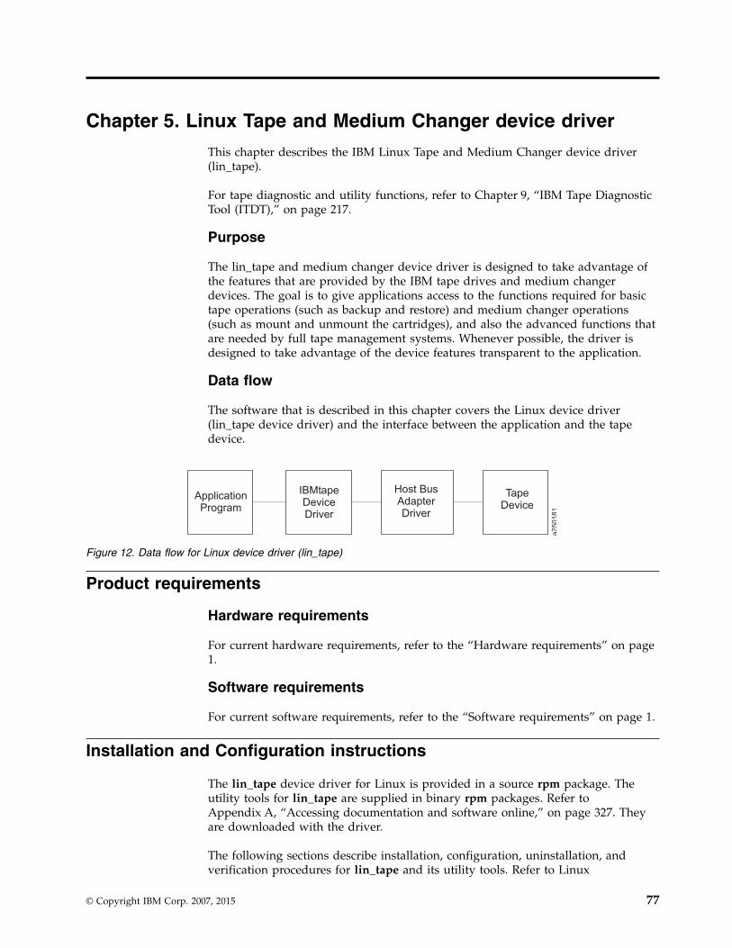
Chapter 5. Linux Tape and Medium Changer device driver
This chapter describes the IBM Linux Tape and Medium Changer device driver(lin_tape).
For tape diagnostic and utility functions, refer to Chapter 9, “IBM Tape DiagnosticTool (ITDT),” on page 217.
Purpose
The lin_tape and medium changer device driver is designed to take advantage ofthe features that are provided by the IBM tape drives and medium changerdevices. The goal is to give applications access to the functions required for basictape operations (such as backup and restore) and medium changer operations(such as mount and unmount the cartridges), and also the advanced functions thatare needed by full tape management systems. Whenever possible, the driver isdesigned to take advantage of the device features transparent to the application.
Data flow
The software that is described in this chapter covers the Linux device driver(lin_tape device driver) and the interface between the application and the tapedevice.
Product requirements
Hardware requirements
For current hardware requirements, refer to the “Hardware requirements” on page1.
Software requirements
For current software requirements, refer to the “Software requirements” on page 1.
Installation and Configuration instructions
The lin_tape device driver for Linux is provided in a source rpm package. Theutility tools for lin_tape are supplied in binary rpm packages. Refer toAppendix A, “Accessing documentation and software online,” on page 327. Theyare downloaded with the driver.
The following sections describe installation, configuration, uninstallation, andverification procedures for lin_tape and its utility tools. Refer to Linux
IBMtapeDeviceDriver
Host BusAdapterDriver
TapeDevice
ApplicationProgram
a250181
Figure 12. Data flow for Linux device driver (lin_tape)
© Copyright IBM Corp. 2007, 2015 77
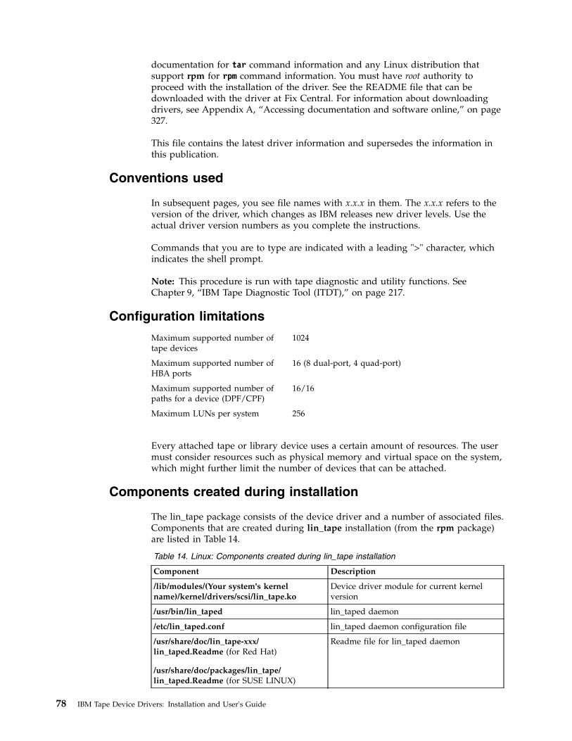
documentation for tar command information and any Linux distribution thatsupport rpm for rpm command information. You must have root authority toproceed with the installation of the driver. See the README file that can bedownloaded with the driver at Fix Central. For information about downloadingdrivers, see Appendix A, “Accessing documentation and software online,” on page327.
This file contains the latest driver information and supersedes the information inthis publication.
Conventions used
In subsequent pages, you see file names with x.x.x in them. The x.x.x refers to theversion of the driver, which changes as IBM releases new driver levels. Use theactual driver version numbers as you complete the instructions.
Commands that you are to type are indicated with a leading ">" character, whichindicates the shell prompt.
Note: This procedure is run with tape diagnostic and utility functions. SeeChapter 9, “IBM Tape Diagnostic Tool (ITDT),” on page 217.
Configuration limitations
Maximum supported number oftape devices
1024
Maximum supported number ofHBA ports
16 (8 dual-port, 4 quad-port)
Maximum supported number ofpaths for a device (DPF/CPF)
16/16
Maximum LUNs per system 256
Every attached tape or library device uses a certain amount of resources. The usermust consider resources such as physical memory and virtual space on the system,which might further limit the number of devices that can be attached.
Components created during installation
The lin_tape package consists of the device driver and a number of associated files.Components that are created during lin_tape installation (from the rpm package)are listed in Table 14.
Table 14. Linux: Components created during lin_tape installation
Component Description
/lib/modules/(Your system's kernelname)/kernel/drivers/scsi/lin_tape.ko
Device driver module for current kernelversion
/usr/bin/lin_taped lin_taped daemon
/etc/lin_taped.conf lin_taped daemon configuration file
/usr/share/doc/lin_tape-xxx/lin_taped.Readme (for Red Hat)
/usr/share/doc/packages/lin_tape/lin_taped.Readme (for SUSE LINUX)
Readme file for lin_taped daemon
78 IBM Tape Device Drivers: Installation and User's Guide

Table 14. Linux: Components created during lin_tape installation (continued)
Component Description
/usr/share/doc/lin_tape-xxx/copying (for RedHat)
/usr/share/doc/packages/lin_tape/copying(for SUSE LINUX)
License documentation for lin_tape
Installation procedure
If lin_tape is already installed on your system, refer to the “Updating procedure.”This section assumes that you are installing the lin_tape device driver onto asystem where it is not currently installed.
If you are installing lin_tape on a system that is running Linux for S/390® orLinux for zSeries, ensure that the OpenFCP adapter device driver zfcp is loaded inthe kernel. Refer to “Configuring Tape and Medium Changer devices on IBMSystem z models” on page 81 for how to configure and install zfcp.
Make sure that the C/C++ development and kernel development packages areinstalled on your system. To install the lin_tape driver with all the added value ofthe lin_taped daemon, complete the following steps.1. Download the appropriate level of the source RPM package to a directory of
your choice on the Linux kernel for which you want to install it.2. Run rpmbuild --rebuild <filename>, where: <filename> is the name of the RPM
file. A binary RPM package is created for your kernel from the source RPMpackage. For example,>rpmbuild --rebuild lin_tape-1.x.x.x.0-1.src.rpm
3. Output from the build is printed to your screen. Near the end of the output, aline indicates the file name and location of your binary RPM package. Forexample, a line similar to the following is output to your screen.Wrote: /usr/src/redhat/RPMS/i386/lin_tape-1.x.x.x.0-1.i386.rpm
4. To install the lin_tape driver from the binary package, run >rpm -ivh<filename> For example,>rpm -ivh /usr/src/redhat/RPMS/i386/lin_tape-1.x.x.x.0-1.i386.rpm
5. To install the lin_taped daemon, download it to your Linux file system and runrpm -ivh on the daemon RPM file. For example,>rpm -ivh /usr/src/redhat/RPMS/i386/lin_taped-1.x.x.x.0-rhel5.i386.rpm
Updating procedure
If your current lin_tape device driver was installed from a rpm packagepreviously, you can uninstall the driver first, then install the newer version. Forexample,
>rpm -e lin_taped>rpm -e lin_tape>rpmbuild --rebuild lin_tape.x.x.x.i386.rpm>rpm -i lin_tape.x.x.x.i386.rpm
Note: All tape devices that use the lin_tape device driver must be closed andcannot be in use when lin_tape is uninstalled.
Chapter 5. Linux Tape and Medium Changer device driver 79

Querying the installed package
The query is supported for the lin_tape device driver rpm package only.
The installed rpm package can be queried by running the following commands toshow information that is associated with the package.
To show information about lin_tape -
>rpm -qi lin_tape
To show the file list, enter the command
>rpm -ql lin_tape
To show the states of files in the package, for example, normal, not installed, orreplaced -
>rpm -qs lin_tape
Configuring Tape and Medium Changer devices onIntel-compatible systems
If you did not physically attach your tape and medium changer devices to yourLinux server, complete the following steps.1. Halt the Linux server.2. Power down the Linux server.3. Physically attach the tape and medium changers to the host bus adapter cards.
Consult your hardware documentation for details.4. Power on the tape and medium changer devices. Verify that they complete the
initialization process.5. Power on and boot the Linux server.
Note: Hot plugging SCSI devices while the Linux server is running can causehardware damage.
After the driver software is installed and a tape device is connected to the adapter,the device can be configured and made available for use. Access to the device isnot provided until the device is configured.
If your system is attached to an IBM 3583 tape library with the integrated router,before the QLogic driver is installed, set the host type of the router to solaris andmake sure that the logical unit numbers of the control unit, medium changer, andthe connected tape drives are contiguous. Otherwise, the QLogic device driverdoes not recognize all of the attached devices. To view the LUNs of attacheddevices, log on to the router and use the fcShowDevs command. If the LUNs arenot contiguous, use the mapCompressDatabase command to delete the invalid LUNsand make the valid LUNs contiguous.
When you run the lin_tape kernel module, it creates special files in the /devdirectory.
80 IBM Tape Device Drivers: Installation and User's Guide

Configuring Tape and Medium Changer devices on IBMSystem p models
Follow the same instructions as documented in the previous section. You mustconfigure the Emulex Linux device driver if you have Fibre Channel tape devicesthat are attached to your System p (also known as pSeries) system.
Configuring Tape and Medium Changer devices on IBMSystem z models
The Fibre Channel topology that is supported for System z® is point-to-point andfabric. Refer to the Linux on System z Fibre Channel documents for details on thesupported configurations for Fibre Channel device attachment. The Linux FibreChannel adapter device driver zfcp is available in the kernel that supports zSeriesFibre Channel Protocol. The zfcp device configuration methods in 2.6 and 2.4kernels are different. For 2.6 kernels, refer to appropriate chapter in the Linux onSystem z document entitled Linux on System z: Device Drivers, Features, andCommands.
For 2.4 kernels, there are three ways to load the zfcp device driver to see theattached tape devices.1. Create a /etc/zfcp.conf file and make a ramdisk to statically attach tape devices
into your system. You can use this method only if you have a persistentmapping in a SAN environment. Every time that you reboot the system, thezfcp is automatically loaded and the tape devices can be seen from the system.You must add the device map into this file. The following is an example ofzfcp.conf.0xf1c0 0x1:0x5005076300402733 0x0:0x0000000000000000;\0xf1c1 0x1:0x5005076300402733 0x0:0x0001000000000000
The zfcp device driver uses the "map" module parameter to recognize aphysically attached tape device. map takes the following format,map="<devno><port scsi-id>:<wwpn><unit-scsi-lun>:<fcp-lun>;...."
Where
devno The device number of the host bus adapter (16 bits, see/proc/subchannels). It is 0xf1c0 or 0xf1c1 in the previous example.
port scsi-idLinux internal SCSI ID assigned to the Fibre Channel port of the SCSItarget device (32-bit, must not be 0, must be a unique one-to-onemapping for each worldwide port name. It is 0x1 in the previousexample.
wwpn Worldwide port name that identifies the Fibre Channel port of the SCSItarget device (64-bit). It is 0x5005076300402733 in the previous example.
unit scsi-lunLinux internal SCSI Logical Unit Number (32-bit). It is 0x0 in theprevious example.
fcp-lunLogical Unit Number that is associated with the SCSI target device(64-bit). In the previous example, 0x0000000000000000 is the LogicalUnit Number 0, and 0x0001000000000000 is the Logical Unit Number 1.
Chapter 5. Linux Tape and Medium Changer device driver 81

For tape attachment, each logical unit number must be associated with aunique devno. If you use the same devno numbers for several logical units,you can ensure that each <unit-scsi-lun> is unique. After /etc/zfcp.conf iscreated, run the following commands.>mk_initrd>zipl
Then, reboot the system. After it is booted up, your tape device must be shownin /proc/scsi/scsi file.
2. Modify the /etc/modules.conf file to add the zfcp module parameters; then runthe depmod –A and modprobe zfcp command.
Note: Do not use this choice together with the first one, otherwise it causesconflicts.The zfcp map in /etc/modules.conf always takes higher priority than the mapin /etc/zfcp.conf.The following example demonstrates the zfcp configuration in/etc/modules.conf.options zfcp map="\0xf1c0 0x1:0x5005076300402733 0x0:0x0000000000000000;\0xf1c1 0x1:0x5005076300402733 0x0:0x0001000000000000"
The map arguments are the same as the ones listed in for the /etc/zfcp.conf file.After the /etc/modules.conf file is modified, save and close it. Then, run thefollowing command.>depmod -A>modprobe zfcp
This action installs the zfcp device driver and all of its prerequisite kernelmodules. Now you can check the file /proc/scsi/scsi to see if all of the attachedtape devices are shown in this file. If not, then check the Fibre Channelconnection, such as the fibre cables, or if the devices are powered on.Then, run the following commands to install zfcp.>rmmod zfcp>modprobe zfcp
3. Run the modprobe zfcp command first, then dynamically add a tape device intothe system after you physically attach a Fibre Channel tape device to theswitch.If you physically attach a tape device on the switch and zfcp is already loaded,you do not need to reboot the Linux system to add this entry in the/proc/scsi/scsi file. The zfcp device driver provides an "add_map" proc systementry under the directory /proc/scsi/zfcp to dynamically add the device into thesystem. For example, to add two logical units from the example in Step 2 intothe system, you can issue the following commands.
> echo "0xf1c0 0x1:0x5005076300402733 0x0:0x0000000000000000;\0xf1c1 0x1:0x5005076300402733 0x0:0x0001000000000000"> /proc/scsi/zfcp/add_map> echo "scsi add-single-device 0 0 1 0" > /proc/scsi/scsi> echo "scsi add-single-device 1 0 1 1" > /proc/scsi/scsi
The scsi add-single-device takes four parameters, corresponding to the fourparameters scsi, Channel, Id, and Lun in the /proc/scsi/scsi file. The value ofscsi is 0 for the first devno, 1 for the second devno (if it is different from thefirst devno), and so on. The value of Channel can start from 0 for each different
82 IBM Tape Device Drivers: Installation and User's Guide

scsi value. The value of Id is the one you use for <unit scsi-lun> in theprevious mapping. The value of Lun is the logical unit number of the targetdevice, for example, the last number in the previous mapping. Currently, thezfcp device driver does not support dynamically removing the attacheddevices. If you must remove the tape devices from the system, do rmmod zfcp.Then, you can delete the entry in /etc/modules.conf and reload zfcp, or reloadzfcp first and dynamically add the devices that you want. After you finishedall the mapping, if you can see all of the attached tape devices in/proc/scsi/scsi, you successfully attached those devices to your system. Next,you can install the lin_tape device driver. Refer to the “Installation procedure”on page 79 section for the instructions on how to install lin_tape.
Uninstallation procedure
Note: All tape devices that use the lin_tape driver must be closed and cannot bein use when lin_tape is uninstalled or the uninstall fails.
Run the following command.>rpm -e lin_tape ---to remove
Tape drive, media, and device driver parameters
This chapter describes the parameters that control the operating modes of the IBMLinux Tape and Medium Changer device driver.
Configuration parameters
The configuration parameters are used to set the operating mode of the tape driveand device driver when a device is opened. The installation defaults are providedfor all parameters initially. These parameters are kept on reopen, but are alwaysrestored back to the default values when the lin_tape device driver is reinstalled.
Note: This procedure is completed with tape diagnostic and utility functions. SeeChapter 9, “IBM Tape Diagnostic Tool (ITDT),” on page 217.
The nonchangeable configuration parameters arev Autoloadingv Density codev Emulate autoloaderv Hook wordv Maximum block sizev Minimum block sizev Medium typev Read SILI bitv Record space modev Volume ID for loggingv Write protect
The changeable configuration parameters arev Barcode lengthv Block size
Chapter 5. Linux Tape and Medium Changer device driver 83

v Buffered modev Capacity scalingv Compressionv Disable auto drive dumpv Disable SIM loggingv Dynamic attributesv Loggingv Logical write protectv Maximum SCSI transfer lengthv Read past filemarkv Rewind immediatev Tracev Trailer labelsv Busy Retry
Nonchangeable parameters
The configuration parameters are used to set the operating mode of the tape driveand device driver when a device is opened. The nonchangeable parameters aredetailed as follows.
Autoloading
This parameter enables the autoloading feature of the device driver. It is disabledby default and cannot be changed.
Capacity scaling
This parameter sets the capacity or logical length of the current tape. By reducingthe capacity of the tape, the tape drive can access data faster at the expense of datacapacity. Capacity scaling is not supported currently but might be supported infuture releases of lin_tape.
Density code
This parameter is the density setting for the currently loaded tape. Some tapedevices support multiple densities and report the current setting in this field. Itcannot be changed by the application.
Emulate autoloader
This parameter currently is not supported and is ignored.
Hook word
This parameter is not supported in the lin_tape device driver.
Logical write protect
This parameter sets or resets the logical write protect of the current tape. Thisfeature is not supported currently but might be supported in future releases of thelin_tape.
84 IBM Tape Device Drivers: Installation and User's Guide

Maximum block size
This parameter is the maximum block size for the device.
Minimum block size
This parameter is the minimum block size for the device.
Medium type
This parameter is the media type of the current loaded tape. Some tape devicessupport multiple media types and different values are reported in this field.
Read SILI bit
SILI bit currently is not supported due to limitations associated with the Linuxenvironment. SILI bit support can be enabled in future releases of the lin_tape.
Record space mode
This parameter specifies how the device driver operates when a forward orbackward space record operation encounters a filemark. Only the SCSI mode issupported by lin_tape. When a forward or backward space record operation isissued to the driver and a filemark is encountered, the device driver returns -1 andthe errno variable is set to input/output error (EIO). On the forward spaceoperation, the tape is left-positioned after the filemark (the end of tape side of thefilemark). On the backward space operation, the tape is positioned before thefilemark (the beginning of tape side of the filemark).
Volume ID for logging
This parameter is the volume ID of the currently loaded tape. The lin_tape devicedriver ignores this field.
Write protect
This parameter is set to TRUE if the currently mounted tape is logically orphysically write protected.
Changeable parameters
The configuration parameters are used to set the operating mode of the tape driveand device driver when a device is opened. The changeable parameters aredetailed as follows.
Barcode length
This parameter can be set to change the barcode length for a cartridge. For LTOcartridges the default is 8. It can be changed to 6 for LTO 1 and LTO 2 generationcartridges only. For 3592 cartridges the default is set at 6. It can be changed to 8. Inthe /etc/modprobe.conf.local file the following line must be added to reflect thedesired change.options lin_tape ibm3592_barcode=8options lin_tape lto_barcode=6
Stop and start the driver by running these commands.
Chapter 5. Linux Tape and Medium Changer device driver 85

>lin_taped stop>rmmod lin_tape>depmod>modprobe lin_tape (reinstall back)>lin_taped (restart the daemon)
Block size
This parameter specifies the block size that is used for read and write operations.A value of zero means a variable block size. Any other value is a fixed block size.The installation default is zero (variable length block size). Refer to “MaximumSCSI transfer length” on page 88 for guidance.
Buffered mode
This parameter specifies whether read and write operations must be buffered bythe tape device. The default (recommended) value is TRUE.
Capacity scaling
This parameter sets the capacity or logical length of the current tape on EnterpriseTape System 3590 or 3592 tape subsystems. By reducing the capacity of the tape,the tape drive can access data faster at the expense of data capacity. Capacityscaling can be set at 100% for the entire tape (which is the default), or set at 75%,50%, or 25% of the 3590 tape cartridge and more available capacity scaling for the3592 standard 300 GB rewritable data cartridge. Capacity scaling remains with thetape across mounts until it is changed.
Note:
1. The tape position must be at the start of the tape to change this parameter fromits current value.
2. Changing this parameter destroys any existing data on the tape.3. For 3592 media types, capacity scaling is supported only for the standard 300
GB rewritable data cartridge. Attempting to set capacity scaling that is notsupported by a device or the current loaded media always returns 100% andcannot be changed. For example, the 60 GB (Economy Data) cartridge for theIBM 3592 cannot be capacity-scaled and is always 100%.
Compression
Hardware compression is implemented in the device hardware. This parameterturns the hardware compression feature On and Off. If compression is enabled, theeffective performance can increase, based on the compressibility of the data.
The installation default is On (use compression).
Disable auto drive dump
This parameter is provided in the lin_tape version 1.2.2 or later. It is set to FALSEby default. If it is FALSE and the lin_taped daemon is running and if an erroroccurs in the drive that creates a drive dump, the lin_tape device driverautomatically retrieves the drive dump and saves it under the /var/log directoryby default. You can specify another directory in the /etc/lin_taped.conf file. Thedump is labeled with a .dmp extension on the file. Refer to “Configuring andrunning the lin_taped daemon” on page 101 for details.
86 IBM Tape Device Drivers: Installation and User's Guide

Disable SIM logging
This parameter is provided in the lin_tape version 1.2.2 or later. It is set to FALSEby default. If it is FALSE and the lin_taped daemon is running and SIM/MIM datais generated by the drive, the lin_tape device driver automatically retrieves thedata and saves it in a formatted text file under the /var/log directory by default.You can specify another directory in the /etc/lin_taped.conf file. Refer to“Configuring and running the lin_taped daemon” on page 101 for details.
This capacity is not applicable to IBM Ultrium tape drives.
Dynamic attributes
This parameter determines whether dynamic runtime attributes are attempted onopen for supported drives. Default is 1 (on) meaning that the driver automaticallyattempts to set dynamic runtime attributes on open. This parameter can bechanged to 0 (off) in the configuration file before the lin_tape is loaded. It isrecommended to keep on dynamic attributes unless it produces an unexpectedproblem in the environment.
Logging (volume logging)
This parameter turns the volume information logging On or Off. With the lin_tapeversion 1.2.2 and later, the lin_tape device driver provides this support. It is set toOn by default. If logging is On and the lin_taped daemon is running, the lin_tapedevice driver retrieves the full log sense data from the drive whenever a tape isunloaded, or the drive reaches a log threshold. The log file is saved in binaryformat under the directory /var/log by default. You can specify another directoryin /etc/lin_taped.conf file. Refer to “Configuring and running the lin_tapeddaemon” on page 101 for details.
Note: This parameter is volume logging, which is different from error logging.lin_tape provides error logging whenever the lin_taped daemon is running. Referto “Configuring and running the lin_taped daemon” on page 101 for details onerror logging.
Logical write protect
This parameter sets or resets the logical write protect of the current tape onEnterprise Tape System 3590 tape subsystems. The three types of logical writeprotect are associated protect, persistent protect, and write-once read-many(WORM) protect.1. Associated protect remains only while the current tape is mounted or
associated with the tape drive. It is reset when the tape is unloaded or the tapedrive is reset.
2. Persistent protect remains or persists with the tape across mounts until it isreset.
3. WORM protect also remains with the tape across mounts, but unlike persistentprotect it cannot be reset on the tape. After a tape is WORM protected, it cannever be written on again.
Note: The tape position must be at the start of the tape to change this parameterfrom its current value.
Chapter 5. Linux Tape and Medium Changer device driver 87

Maximum SCSI transfer length
In the lin_tape drivers with level lower than 3.0.3, the maximum transfer lengthper device per SCSI command is 262144 bytes (256 KB) by default. Variable blockread/write requests with transfer length greater than the maximum transfer lengthfails [errno: EINVAL]. When a fixed block size is defined, large write requests aresubject to both the granularity of the block size and the maximum transfer length.For example, with a fixed block size of 80000 bytes and maximum transfer lengthof 262144, a write request for 400000 bytes (5 blocks of 80000 each) is written totape in two transfers. The first transfer is 240000 bytes (3 blocks) and the secondtransfer is 160000 (the remaining two blocks). You can increase the maximumtransfer length to enhance the data throughput. This procedure can be done withITDT with the Query/Set Parameters option, or a customized STIOCSETPinput/output control (ioctl) call. However, setting the transfer length greater thanthe default 256 KB does not guarantee a noticeable increase in data throughput.Maximum transfer length of 256 KB is highly recommended.
In lin_tape driver with level 3.0.5 or higher and the open source driver lin_tape,the maximum transfer length is defined as the minimum length that the host busadapter and the tape drive can support. This number is greater than 256 KB. Itcannot be changed by the STIOCSETP ioctl call any more.
Read past filemark
If this parameter is set to true, when a fixed-length read operation encounters afilemark, it returns the number of bytes read before the filemark is encounteredand positions the tape head after the filemark. If the read_past_filemarkparameter is set to false, when the fixed-length read operation encounters afilemark, if data was read, the read function returns the number of bytes read, andpositions the tape head before the filemark. If no data was read, then the readreturns 0 bytes read and positions the tape head after the filemark.
This installation default is FALSE.
Rewind immediate
This parameter sets the immediate bit for rewind commands. If it is set to On, therewind tape operation runs faster, but the next command takes a long time tofinish unless the physical rewind operation is complete. Setting this parameterreduces the amount of time it takes to close a device for a Rewind on Close specialfile.
The installation default is Off (no rewind immediate).
Trace
This parameter turns the trace facility On or Off. With the lin_tape version 1.2.2and later, the lin_tape device driver provides this support. It is set to On bydefault. If trace is On and the lin_taped daemon is running, the lin_tape devicedriver retrieves the trace from the driver if trace level is set to 1 or 2 in the/etc/lin_taped.conf file. The trace file is saved under the directory /var/log bydefault. You can specify another directory in /etc/lin_taped.conf file. Refer to“Configuring and running the lin_taped daemon” on page 101 for details.
88 IBM Tape Device Drivers: Installation and User's Guide

Trailer labels
If this parameter is set to On, then writing records past the early warning mark onthe tape is allowed. The first write operation after detecting the early warningmark fails and the errno variable is set to ENOSPC. No data is written during theoperation. All subsequent write operations are allowed to continue until thephysical end of the volume is reached and errno EIO is returned.
If this parameter is set to Off, then writing records past the early warning mark isnot allowed. Errno variable is set to ENOSPC.
The installation default is On (with trailer labels).
Busy Retry
The parameter busy_retry determines how many times to retry a command whenthe device is busy. Default is 0 (off), and can be set up to 480 in the configurationfile before the lin_tape is loaded.
Special files
After the driver is installed and a device is configured and made available for use,access is provided through the special files. These special files, which consist of thestandard Linux special files for devices, are in the /dev directory.
Special files for the tape device
Each tape device has a set of special files providing access to the same physicaldrive but providing different attributes. Table 15 shows the attributes of the specialfiles.
Note: The asterisk (*) in IBMtape* represents a number assigned to a particulardevice, such as IBMtape0.
For tape drives with attached medium changer devices, the IBMchanger* specialfile provides a separate path for issuing commands to the medium changer. Whenthis special file is opened, the application can view the medium changer as aseparate device. Both the tape and changer special file can be opened at the sametime.
Table 15. Linux: Special files for IBM tape devices
Special file name Rewind on Close
/dev/IBMTape* YES
/dev/IBMTape*n NO
Special files for the Medium Changer device
After the driver is installed and a medium changer device is configured and madeavailable for use, access to the robotic device is provided through the IBMchangerspecial file in the/dev directory. The asterisk (*) represents a number that isassigned to a particular device, such as IBMchanger0. The term IBMchanger is usedfor a SCSI medium changer device. The IBMchanger* special file provides a pathfor issuing commands to control the medium changer robotic device.
Chapter 5. Linux Tape and Medium Changer device driver 89

The file descriptor that results from opening the IBMchanger special file does notsupport the following operations.v Readv Writev Open in Append modev Commands that are designed for a tape device
Persistent Naming Support
Lin_tape Persistent Naming is implemented through the Linux udev utility. Udevis a service that monitors changes in system hardware configuration and completesactions that are based on what devices are attached to the Linux system. It can beconfigured to create symbolic links (persistent names) to a device based onattributes that a driver exports for that device. The persistent name can then beused as the device name to open and complete IO to a tape drive or mediumchanger. This action makes it possible to reference a static name, such as/dev/lin_tape/by-id/lin_tape4801101
This name is always associated with the same physical device, rather than beingrequired to reference the device name /dev/IBMtape0, which can change namesand become /dev/IBMtape1 after the driver is reinstalled.
Lin_tape exports several attributes that can be used as the basis to create persistentnames. These attributes can be reported to the user through udevadm info onrecent Linux kernels, or udevinfo on older Linux kernels. The udevinfo andudevadm are udev management tools. These tools can query the udev database fordevice information and properties that are stored in the udev base for helpcreating udev rules.
Note: Udev, udevinfo, and udevadm are not implemented or maintained by thelin_tape driver. Refer to the man pages for udevadm or udevinfo for details onusage. These man pages are system specific and supersede all information in thisdocument. For questions on these utilities, you must contact your Linux supportrepresentative.
An example is provided on udev for implementing a persistent name. The examplemust be customized to fit a user’s needs and environment.
Note: Variations exist between kernels.
If a tape device is attached to the Linux system with worldwide port name0x123456789ABCDEF0 with a current device name of /dev/IBMtape0, a user can runudevadm information to obtain information on exported attributes for this device.This procedure can be done as follows,>udevadm info --attribute-walk --name /dev/IBMtape0
The output of this command includes something similar toATTRS{serial_num}=="123456789"ATTRS{ww_node_name}=="0x123456789ABCDEF1"ATTRS{ww_port_name}=="0x123456789ABCDEF0"
If you are using udevinfo, enter the previous command as
90 IBM Tape Device Drivers: Installation and User's Guide

>udevinfo -a -p `udevinfo -q path -n /dev/IBMtape0`or>udevinfo -a -p /sys/class/lin_tape/IBMtape0(Both commands return the same information).
Also, on some kernels an attribute ATTRS{xxx} is replaced by SYSFS{xxx}.Furthermore, some kernels use a '=' (single equal sign) to indicate an attributematch and also an assignment. Whereas, other kernels use a '==' (double equalsign) for a match and '=' for assignment. Place the attribute from the attribute listinto your rules file exactly as it appears in the attribute list, as described here.
The ww_port_name is in a rules file that assigns a symbolic link to a device thathas the listed worldwide port name. The file typically is placed in/etc/udev/rules.d, but this location might be changed by the udev_rules directivein the /etc/udev/rules.conf file. In this example, a file is created that is called/etc/udev/rules.d/98-lin_tape.rules and write a single line to the file.KERNEL=="IBMtape*", ATTRS{ww_port_name}=="0x123456789ABCDEF0",
SYMLINK="lin_tape/by-id/lin_tape4801101"
Assuming that the udev service is running and configured correctly, the user caninstall or reinstall lin_tape with modprobe, and the symbolic link is created in the/dev/lin_tape/by-id folder. One line must be added to the 98-lin_tape.rules file foreach wanted symbolic link.
With lin_tape version 2.2.0, a parameter, persistent_n_device, is added to supportpersistent naming of no rewind devices. The default value is 0 (off). To enable thissupport, complete the following steps.1. Modify the 98-lin_tape.rules file to differentiate standard devices and no
rewind devices. For example,KERNEL=="IBMtape*[0-9]", ATTR{serial_num}=="1013000306", SYMLINK="lin_tape/by-id/IBMtape0"KERNEL=="IBMtape*n", ATTR{serial_num}=="1013000306", SYMLINK="lin_tape/by-id/IBMtape0n"
2. Stop the lin_taped daemon.lin_taped stop
3. Unload the lin_tape driver from the memory.modprobe -r lin_tape
4. Add the following line in your /etc/modprobe.conf or /etc/modprobe.conf.localfile (or, if you are running RHEL 6 or higher, in your /etc/modprobe.d/lin_tape.conf file).options lin_tape persistent_n_device=1
5. Reload the lin_tape driver into memory.modprobe lin_tape
Note: Wait at least 10 seconds between step 3 (modprobe -r lin_tape) and step5 (modprobe lin_tape) in order for udev to correctly configure the devices.
6. Check that the devices are all correctly listed with the following command.ls -l /dev/lin_tape/by-id/
7. Restart the lin_taped daemon.lin_taped
Chapter 5. Linux Tape and Medium Changer device driver 91

Control Path failover support for tape libraries
Note: The library control path failover feature code must be installed beforecontrol path failover support is enabled in the Linux lin_tape device driver. Referto“Automatic failover” on page 5 to determine which feature code is required foryour machine type.
The Linux lin_tape device driver control path failover support configures multiplephysical control paths to the same logical library within the device driver. It alsoprovides automatic failover to an alternative control path when a permanent erroroccurs on one path. This support is transparent to the running application.
Configuring and unconfiguring path failover support
Control path failover support is not enabled automatically when the device driveris installed. The Linux lin_tape device driver provides a driver parameteralternate_pathing for you to enable the library control path failover. To enable thefailover support in the lin_tape device driver software, you must do the followingsteps after the lin_tape rpm package is installed:1. lin_taped stop (stop the lin_taped daemon)2. rmmod lin_tape (unload the lin_tape driver from the memory)3. Add the following line in your /etc/modprobe.conf or /etc/modprobe.conf.local
file (or, if you are running RHEL 6 or higher, in your /etc/modprobe.d/lin_tape.conf file)options lin_tape alternate_pathing=1
4. depmod
5. modprobe lin_tape (reload the lin_tape driver into memory)6. lin_taped (restart lin_taped daemon)
You can ignore the Unresolved symbols in /lib/modules/<your kernelname>/drivers/scsi/lin_tape.ko message after the depmod command. You cancheck whether the lin_tape driver recognized multiple control paths for yourlibrary by reading the /proc/scsi/IBMchanger file.v cat/proc/scsi/IBMchanger
If your library lists "Primary" or "Alternate" under "FO Path", you successfullyenabled the control path failover feature for your library. If "NA" is listed under"FO Path", then the control path failover is not enabled. After control path failoversupport is enabled, it remains set until the lin_tape driver is reloaded with thealternate_pathing driver parameter set to OFF. The path failover setting isretained even if the system is rebooted. If you want to turn off the control pathfailover feature in the lin_tape device driver, you can complete the following steps.1. lin_taped stop
2. rmmod lin_tape
3. Delete the following line in your /etc/modprobe.conf file.options lin_tape alternate_pathing=1
4. depmod
5. modprobe lin_tape
6. lin_taped
92 IBM Tape Device Drivers: Installation and User's Guide

Enabling path failover for the sg interface
Through a collaboration effort that is named join driver, control path failover isplanned to be supported through the sg interface.
Note: To validate the lintape version that adds this support, check the fixlist for astatement about SFMP support.
Note: It is important to review hardware and software requirements before pathfailover is enabled. See Chapter 1, “Introduction,” on page 1.
To enable it, the lin_tape_as_sfmp parameter needs to be set at/etc/modprobe.d/lin_tape.conf and to take effectlintaped and lintape isstopped/unloaded and loaded/started as follows:Stop the lin_tape daemon (lin_taped)>lin_taped stopUnload the lin_tape driver (lin_tape)>modprobe -r lin_tape
At /etc/modprobe.d/lin_tape.conf or /etc/modprobe.conf or /etc/modprobe.conf.local file, to add lin_tape_as_sfmp:options lin_tape alternate_pathing=1options lin_tape_as_sfmp=1
Load the lin_tape driver>modprobe lin_tape
Start the daemon>lin_taped start
To disable lin_tape_as_sfmp, follow the same procedure to remove it from theconfiguration file.
Primary and alternative paths
When lin_tape is loaded into kernel memory, the first logical medium changerdevice that lin_tape sees in the system is the primary path for that mediumchanger. The other logical medium changers that lin_tape attached for the samemedium changer are configured as alternative paths. The device driver supportsup to 16 physical paths for a single device. The primary and alternative pathinformation can be obtained by the following command.v cat /proc/scsi/IBMchanger
An example of a /proc/scsi/IBMchanger file:v lin_tape version: 3.0.3v lin_tape major number: 253
Table 16. Attached changer devicesNumber Model SN HBA FO Path0 03584L22 IBM1234567 qla2xxx Primary1 03584L22 IBM1234567 qla2xxx Alternate2 03584L22 IBM1234567 qla2xxx Alternate
The labeling of a logical device as either a primary or alternative path is forinformation only, to
Chapter 5. Linux Tape and Medium Changer device driver 93
|
||
||
||
|||
||||
||
||||||||
||

v Identify the actual number of physical devices that are configured on the systemand a specific logical device that is associated with them. Only one logicaldevice is labeled as the primary path for each physical device. However,multiple logical devices can be labeled as an alternative path for the samedevices.
v Provide information about which logical devices configured on the system havepath failover support enabled.
When lin_tape_as_sfmp is set, sg paths can be queried through pfo paths asfollows:cat /sys/class/pfo/*/paths
Example output:pfo10 sg=/dev/sg10 st=none sf=yes fo=no wwnn=0000013400140405 type=changer2:0:1:1 up last - -3:0:1:1 - - - -
There is only one sg device file name per device that uses all the paths for thisdevice.
Querying primary and alternative path configuration
You can show the primary and alternative path configuration for all devices byreading the /proc/scsi/ IBMchanger file, as explained in “Primary and alternativepaths” on page 93.
Note: Show the primary and alternative path configuration for any device withtape diagnostic and utility functions. Refer to Chapter 9, “IBM Tape DiagnosticTool (ITDT),” on page 217.
Disabling and enabling primary and alternative paths
When you load the lin_tape device driver with the alternate_pathing parameterto be ON, by default, all the available paths for a physical device are enabled.
If it is necessary to disable a path and not run path failover (for example, becauseof maintenance), run commands to disable and then later enable the primary andalternative paths.
The commands to enable and disable primary and alternative paths are tapediagnostic and utility functions.
Note: See Chapter 9, “IBM Tape Diagnostic Tool (ITDT),” on page 217.
Data Path failover and load balancing support for tape drives
Data path failover support is not enabled automatically when the device driver isinstalled. The Linux lin_tape device driver provides a driver parameteralternate_pathing for you to enable the data path failover.
To enable the failover support in the lin_tape device driver software, you mustcomplete the following steps after the lin_tape rpm package is installed.>lin_taped stop (stop the lin_taped daemon)>rmmod lin_tape (unload the lin_tape driver from the memory
94 IBM Tape Device Drivers: Installation and User's Guide
||
|
|
|||
||
If you have IBM 3592 tape drives, add the following line in your/etc/modprobe.conf or /etc/modprobe.conf.local file (or, if you are running RHEL 6or higher, in your /etc/modprobe.d/lin_tape.conf file).options lin_tape alternate_pathing=1
If you have IBM LTO tape drives, the library must have a path failover featurecode. The data path failover license keys are needed to enable the failover if youare running LTO2 drives or if you are running LTO3 drives with old levels of drivecode. DPF keys do not need to be added if you are running the latest drive codeon LTO3 or higher drives.
Add the following line in your /etc/modprobe.conf or /etc/modprobe.conf.local file(or, if you are running RHEL 6 or higher, in your /etc/modprobe.d/lin_tape.conffile).options lin_tape alternate_pathing=1 dpf_keys="abcdefghijklmnop"
abckdefghijklmnop is an example of a data path failover feature key. If you havemultiple libraries and multiple data path failover feature keys, input your keys asfollows.dpf_keys="key1;key2;..."
Save the file, then run the following commands.>depmod>modprobe lin_tape (re-load the lin_tape driver into memory)>lin_taped (re-start lin_taped daemon)
You can ignore the Unresolved symbols in /lib/modules/<your kernelname>/drivers/scsi/lin_tape.ko message after the depmod command. You cancheck if the lin_tape driver recognized multiple paths for your tape drive byreading the /proc/scsi/IBMtape file.>cat /proc/scsi/IBMtape
If your tape drive lists "Primary" or "Alternate" under "FO Path", you successfullyenabled data path failover feature for your tape drive. If it is "NA" listed under"FO Path", then the data path failover is not enabled. After the path failoversupport is enabled, it remains set until the lin_tape driver is reloaded with thealternate_pathing driver parameter set to OFF. The path failover setting isretained even if the system is rebooted. If you want to turn off the data pathfailover feature in the lin_tape device driver, you can run the following steps.>lin_taped stop>rmmod lin_tape
Delete the following line in your /etc/modules.conf file: options lin_tapealternate_pathing=1.>depmod>modprobe lin_tape>lin_taped
Enabling path failover for st and sg interface
Through a collaboration effort that is named join driver, control path failover isplanned to be supported through st and sg interfaces.
Note: To validate the lintape version that adds this support, check the fixlist for astatement about SFMP support.
Chapter 5. Linux Tape and Medium Changer device driver 95
|
||
||

Note: It is important to review hardware and software requirements before pathfailover is enabled. See Chapter 1, “Introduction,” on page 1.
To enable it, the lin_tape_as_sfmp parameter needs to be set at/etc/modprobe.d/lin_tape.conf, and to take effect lintaped and lintape must bestopped/unloaded and loaded/started as follows:Stop the lin_tape daemon (lin_taped)>lin_taped stopUnload the lin_tape driver (lin_tape)>modprobe -r lin_tape
At /etc/modprobe.d/lin_tape.conf or /etc/modprobe.conf or /etc/modprobe.conf.local file, to add lin_tape_as_sfmp:options lin_tape alternate_pathing=1options lin_tape_as_sfmp=1
Load the lin_tape driver>modprobe lin_tape
Start the daemon>lin_taped start
To disable lin_tape_as_sfmp, follow the same procedure to remove it from theconfiguration file.
Primary and alternative paths
When the lin_tape device driver is loaded into kernel memory with path failoversupport enabled, the first logic device that lin_tape sees always becomes theprimary path. The other logical devices that lin_tape sees are configured as thealternative paths. The device driver supports up to 16 physical paths for a singledevice.
The primary and alternative path information can be obtained by the followingcommand.>cat /proc/scsi/IBMtape
The following is an example of a /proc/scsi/IBMtape:lin_tape version: 3.0.3lin_tape major number: 253
Table 17. Attached tape devices
Number Model SN HBA FO Path
0 03592 IBM1234567 qla2xxx Primary
1 03592 IBM1234567 qla2xxx Alternate
The labeling of a logical device as either a primary or alternative path is forinformation only tov Identify the actual number of physical devices that are configured on the system
and a specific logical device that is associated with them. Only one logicaldevice is labeled the primary path for each physical device. However, many(multiple) logical devices can be labeled as an alternative path for the samedevices.
v Provide information about which logical devices configured on the system havepath failover support enabled.
96 IBM Tape Device Drivers: Installation and User's Guide
||
|||
||||
||
||||||||
||

When lin_tape_as_sfmp is set, st and sg paths can be queried through pfo paths asfollows:cat /sys/class/pfo/*/paths
Example output:pfo9 sg=/dev/sg9 st=/dev/st0 sf=yes fo=no wwnn=500507630f04be07 type=tape2:0:1:0 up last - wwpn=500507630f44be073:0:1:0 - - - -
Only one st and one sg device file name per device can use all the paths for thatdevice.
Querying primary and alternative path configuration
You can show the primary and alternative path configuration for all devices byreading the /proc/scsi/IBMtape file, as explained in “Primary and alternativepaths” on page 96.
Note: Show the primary and alternative path configuration for any device withtape diagnostic and utility functions. Refer to Chapter 9, “IBM Tape DiagnosticTool (ITDT),” on page 217.
Disabling and enabling primary and alternative paths
If it is necessary to disable a path and not run path failover (for example, becauseof maintenance), run commands to disable and then enable the primary andalternative paths.
The commands to enable and disable primary and alternative paths are tapediagnostic and utility functions.
Note: See Chapter 9, “IBM Tape Diagnostic Tool (ITDT),” on page 217.
Tape Reserve Type
This parameter causes lin_tape to issue SCSI-3 persistent reserves to a tape drivewhenever a reservation is attempted. Persistent reserves are automatically issued ifdata path failover is used, and therefore setting the parameter is unnecessary. Thisparameter can be set only when lin_tape is installed. To set it, add the followingline to /etc/modprobe.conf or /etc/modprobe.conf.local (or, if you are runningRHEL 6 or higher, to /etc/modprobe.d/lin_tape.conf):options lin_tape tape_reserve_type=persistent
Open source device driver - lin_tape
The lin_tape device driver is the new device driver for the Linux 2.6 kernels toreplace the closed-source driver IBMtape. In most respects, it behaves the same asthe closed-source IBMtape device driver. This section covers significant differencesbetween the IBMtape driver and the lin_tape driver.
Comparing IBMtape and lin_tape
Table 18 on page 98 compares the names for various components of the IBMtapeand lin_tape device drivers.
Chapter 5. Linux Tape and Medium Changer device driver 97
||
|
|
|||
||

Table 18. Comparing IBMtape and lin_tape
Component IBMtape Lin_tape
Driver name IBMtape lin_tape
Module name IBMtape.ko lin_tape.ko
Special files /dev/IBMtape0
/dev/IBMchanger0, etc.
No change
proc entry /proc/scsi/IBMtape
/proc/scsi/IBMchanger
No change
Daemon name IBMtaped lin_taped
Daemon configuration file /etc/IBMtaped.conf /etc/lin_taped.conf
Daemon trace files /var/log/IBMtape.trace
/var/log/IBMtape.errorlog
/var/log/lin_tape.trace
/var/log/lin_tape.errorlog
Installation
Installation of the lin_tape driver is the same as for the IBMtape driver, exceptthat IBMtape must be replaced with lin_tape in the installation instructions. Referto “Installation and Configuration instructions” on page 77 for details.
The lin_tape driver cannot be installed if the IBMtape driver is already installed. Ifthe IBMtape driver is installed, first uninstall the IBMtape driver, and then installthe lin_tape driver. With RHEL4 and SLES10, driver removal also requires a rebootof the server, since the IBMtape driver module is "permanent" in thesedistributions.
Driver parameters and special device files
The driver parameters are not changed for the lin_tape driver. However, it isimportant that the module parameters, such as alternate_pathingand dpf_keys,must now be applied to the lin_tape module, instead of the IBMtape module. Forexample, in the /etc/modprobe.conf or /etc/modprobe.conf.local file (or, if you arerunning RHEL 6 or higher, the /etc/modprobe.d/lin_tape.conf file), add thefollowing line for LTO library's path failover:options lin_tape alternate_pathing=1 dpf_keys="abcdefghijklmnop"
abckdefghijklmnop is an example of a data path failover feature key.
The special device files for the lin_tape driver are the same as for the IBMtapedriver. Refer to “Special files for the tape device” on page 89 and “Special files forthe Medium Changer device” on page 89 for details on special device files.
Taking devices offline and completing maintenance
Input and output must be quiesced and all driver handles must be closed before alin_tape device is taken offline. It is recommended to remove the lin_tape drivermodule and the HBA driver module before maintenance is done or the physicaltopology of the tape drive or library environment is changed. Lin_tape can beremoved by the following command at the shell prompt.rmmod lin_tape
98 IBM Tape Device Drivers: Installation and User's Guide
Likewise, the HBA module can be removed by the following command, where"HBA_driver" is your specific HBA driver.rmmod <HBA_driver>
After the maintenance is complete and the environment is ready to issue input andoutput, the drivers must be reinstalled in reverse order. This procedure is typicallydone bymodprobe <HBA_driver>modprobe lin_tape
Path failover support
Path failover support in lin_tape is the same. However, with the lin_tape driver,failover support is provided through the lin_taped daemon. If the lin_tapeddaemon is not running, neither control path failover nor data path failover isattempted. The lin_taped daemon is started automatically when the lin_tape driveris loaded.
To check whether the lin_taped daemon is running, run the following command.lin_taped status
This command indicates whether the lin_taped daemon is running. If the/proc/scsi/IBMtape and /proc/scsi/IBMchanger files indicate "NA" for "FO Path",this answer indicates that failover support for that device is not enabled. If allother settings are correct, but "FO Path" is incorrectly indicating "NA", confirm thatthe lin_taped daemon is running.
For details about path failover support, refer to “Control Path failover support fortape libraries” on page 92 and “Data Path failover and load balancing support fortape drives” on page 94.
lin_taped daemon
The lin_taped daemon uses the same command-line arguments as the IBMtapeddaemon. The lin_taped configuration file is the same as the IBMtapedconfiguration file, but is renamed to lin_taped.conf. Refer to“Configuring andrunning the lin_taped daemon” on page 101 for information.
System-managed encryption
Configuring device drivers
Note: System-managed encryption (SME) on Linux requires that the lin_tapeddaemon is running.
The device driver SME settings can be set for all drives at once with thedefault_sys_encryption_proxy and default_sys_encryption_write module options.
If no options are specified in the registry, the driver uses the default values for theparameters.v The default value for default_sys_encryption_proxy is 1.
This value causes the device driver to handle encryption key requests, if thedrive is set up for system-managed encryption. This value does not need to be
Chapter 5. Linux Tape and Medium Changer device driver 99

changed. A value of 0 causes the device driver to ignore encryption key requestsfor system-managed encryption drives, and is not desirable.
v The default value for default_sys_encryption_write is 2.This value causes the device driver to leave the encryption write-from-BOPsettings alone. It does not turn on or turn off encryption writing, but insteaduses the settings that are already in the drive. If encryption is not set uppreviously, then the drive writes unencrypted data. A value of 0 causes thedevice driver to write unencrypted data. A value of 1 causes the device driver towrite encrypted data.
The module options can be specified in the /etc/modprobe.conf,/etc/modprobe.conf.local, or /etc/modprobe.d/lin_tape.conf files, the same as otherlin_tape module parameters.
For example, to turn on SME to write/read encrypted data,1. Add the following line:
options lin_tape default_sys_encryption_write=1
2. Then, run the following commands.>lin_taped stop>rmmod lin_tape>depmod>modprobe lin_tape (reinstall back)>lin_taped (restart the daemon)
The default settings are used to initialize the settings for all connected drives.
To modify the settings for individual drives, the settings are sys_encryption_writeand sys_encryption_proxy. They have the same definitions and values as thesimilarly named "default" parameters, except that the settings apply only toindividual drives.
These settings are available as part of the sysfs infrastructure. For each drive, thereare two files, named sys_encryption_write and sys_encryption_proxy, in the/sys/class/lin_tape/{DEVICE}/ directory, where: {DEVICE} is the device name,such as IBMtape0. The contents of these files indicate the current setting for theparameter for that particular drive. The setting can be changed by writing adifferent value for the parameter to the file.
For example, to change the sys_encryption_write setting for IBMtape0 to ON(which has a value of 1), enter the following at a command line.echo 1">/sys/class/lin_tape/IBMtape0/sys_encryption_write
Note: The driver encryption parameters for individual drives are not persistentbetween loads of the lin_tape driver. If you remove the lin_tape driver, and thenreload it, the individual settings for all drives are the same as the "default" settingsin /etc/modprobe.conf, /etc/modprobe.conf.local, or /etc/modprobe.d/lin_tape.conf.
The ibmekm.conf file, which contains the configuration that the EKM servers use,is installed in the /etc/ directory when lin_tape is installed. Instructions formodifying this file are found within the file itself.
Querying tape drive configuration
The following is an example of the output when the drive is configured forsystem-managed encryption, with encryption turned on.
100 IBM Tape Device Drivers: Installation and User's Guide

issuing query encryption status...encryption capable......Yesencryption method.......METHOD_SYSTEMencryption state........ON
Problem determination
A set of tools is provided with the device driver to determine whether the devicedriver and the tape device are functioning correctly.
Tracing driver modules
By default, the driver prints minimal kernel trace messages to the system log at/var/log/messages. The minimal information includes notification that a device isrecognized or taken offline and also the most serious of error conditions. If a moreverbose trace is wanted, the variable /sys/bus/scsi/drivers/lin_tape/lin_tape_debug mustcontain the value 1. This procedure can be accomplished in one of two ways -v Add the following line to /etc/modprobe.conf, /etc/modprobe.conf.local, or
/etc/modprobe.d/lin_tape.conf.options lin_tape lin_tape_debug=1
Then reinstall lin_tape. This action causes the lin_tape_debug variable to be setevery time lin_tape is loaded.
v Issue the following command from the shell.echo 1 > /sys/bus/scsi/drivers/lin_tape/lin_tape_debug
This action causes the lin_tape_debug variable to be set only until lin_tape isuninstalled or until the variable is set back to 0.
Configuring and running the lin_taped daemon
Starting with lin_tape version 1.2.5, the lin_tape device driver provides an errordiagnostic daemon (lin_taped) which provides the following capabilities:1. Error logging and tracing2. When drive dumps, log sense data, or SIM/MIM error information is created
by the tape drive, the daemon automatically retrieves that data and saves it tothe hard disk drive on your Linux system.
3. Failover and load balancing4. Encryption
Because lin_taped requires a minimal amount of system resource and because itprovides these necessary diagnostic capabilities, IBM recommends that you leavethe daemon always enabled.
Installing lin_taped
lin_taped is automatically installed at/usr/bin/lin_taped when you install thelin_tape device driver with the rpm or tar package. Refer to“Installation andConfiguration instructions” on page 77 for instructions on installing the lin_tapedevice driver.
Chapter 5. Linux Tape and Medium Changer device driver 101

Configuring lin_taped
You can customize the operation of lin_taped by modifying its configuration file,which is at /etc/lin_taped.conf. The daemon reads only the configuration file whenit starts; so if you modify the configuration file, stop the daemon, and restart it sothat your modifications are recognized by the daemon.
Tracing:
Three levels of tracing are supported for the lin_taped daemon. lin_taped tracing isa complement to, but is different from, tracing of the kernel module that isdescribed in “Tracing driver modules” on page 101. The lin_taped tracing levelsare defined as follows:
0 With tracing set to 0, lin_taped records minimal tracing.
1 With tracing set to 1, lin_taped records information that is associated with each ioctlcalled. If a device error occurs and SCSI sense data is obtained from the device, asubset of that sense data is also recorded. The default setting for tracing.
2 With tracing set to 2, lin_taped records tracing messages for each SCSI command. Ifa device error occurs and SCSI sense data is obtained form the device, all sense datais also recorded. This tracing level is used only when a specific problem is beingdiagnosed due to the potential for huge amounts of data that is generated.
Set the lin_tapeTrace variable in the /etc/lin_taped.conf file to 0, 1, or 2, dependingon what level of tracing you want. If the lin_tapeTrace variable is set to an invalidnumber, the lin_taped daemon does not start.
Tracing information is written to a file named /var/log/lin_tape.trace, by default.Information is written into the file until it is 1 MB in size, by default. After 1 MB ofinformation is written, the file is archived (using the Linux ar command) into filelin_tape.a in the same directory. In the archive, the file name is renamed tolin_tape.trace.timestamp, where timestamp reflects the time that the file wasarchived.
You can change the directory to which the tracing information is written or thedefault maximum size of the trace file by modifying settings in the lin_taped.conffile. Refer to the instructions in the lin_taped.conf file for details.
Error logging:
lin_taped records certain error messages from the lin_tape device driver in a filenamed /var/log/lin_tape.errorlog, by default. Information is written into the fileuntil it is 1 MB in size, by default. After 1 MB of trace information is written, thefile is archived (with the Linux ar command) into file lin_tape.a in the samedirectory. In the archive, the file name is renamed to lin_tape.errorlog.timestamp,where timestamp reflects the time that the file was archived.
You can change the directory to which the error logging information is written orthe default maximum size of the error log file by modifying settings in thelin_taped.conf file. Refer to the instructions in the lin_taped.conf file for details.
Whenever the lin_taped daemon is running, error logging is enabled if tracing isenabled. Following is an example an error log record.IBMtape0---E0001 Tue Sep 10 14:04:57 2002
Scsi Path : 03 00 00 00CDB Command : 01 00 00 00 00 00Status Code : 08 00 00 01
102 IBM Tape Device Drivers: Installation and User's Guide
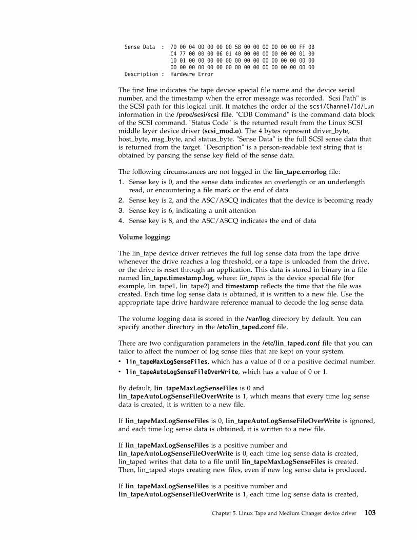
Sense Data : 70 00 04 00 00 00 00 58 00 00 00 00 00 00 FF 0BC4 77 00 00 00 06 01 40 00 00 00 00 00 00 01 0010 01 00 00 00 00 00 00 00 00 00 00 00 00 00 0000 00 00 00 00 00 00 00 00 00 00 00 00 00 00 00
Description : Hardware Error
The first line indicates the tape device special file name and the device serialnumber, and the timestamp when the error message was recorded. "Scsi Path" isthe SCSI path for this logical unit. It matches the order of the scsi/Channel/Id/Luninformation in the /proc/scsi/scsi file. "CDB Command" is the command data blockof the SCSI command. "Status Code" is the returned result from the Linux SCSImiddle layer device driver (scsi_mod.o). The 4 bytes represent driver_byte,host_byte, msg_byte, and status_byte. "Sense Data" is the full SCSI sense data thatis returned from the target. "Description" is a person-readable text string that isobtained by parsing the sense key field of the sense data.
The following circumstances are not logged in the lin_tape.errorlog file:1. Sense key is 0, and the sense data indicates an overlength or an underlength
read, or encountering a file mark or the end of data2. Sense key is 2, and the ASC/ASCQ indicates that the device is becoming ready3. Sense key is 6, indicating a unit attention4. Sense key is 8, and the ASC/ASCQ indicates the end of data
Volume logging:
The lin_tape device driver retrieves the full log sense data from the tape drivewhenever the drive reaches a log threshold, or a tape is unloaded from the drive,or the drive is reset through an application. This data is stored in binary in a filenamed lin_tape.timestamp.log, where: lin_tapen is the device special file (forexample, lin_tape1, lin_tape2) and timestamp reflects the time that the file wascreated. Each time log sense data is obtained, it is written to a new file. Use theappropriate tape drive hardware reference manual to decode the log sense data.
The volume logging data is stored in the /var/log directory by default. You canspecify another directory in the /etc/lin_taped.conf file.
There are two configuration parameters in the /etc/lin_taped.conf file that you cantailor to affect the number of log sense files that are kept on your system.v lin_tapeMaxLogSenseFiles, which has a value of 0 or a positive decimal number.v lin_tapeAutoLogSenseFileOverWrite, which has a value of 0 or 1.
By default, lin_tapeMaxLogSenseFiles is 0 andlin_tapeAutoLogSenseFileOverWrite is 1, which means that every time log sensedata is created, it is written to a new file.
If lin_tapeMaxLogSenseFiles is 0, lin_tapeAutoLogSenseFileOverWrite is ignored,and each time log sense data is obtained, it is written to a new file.
If lin_tapeMaxLogSenseFiles is a positive number andlin_tapeAutoLogSenseFileOverWrite is 0, each time log sense data is created,lin_taped writes that data to a file until lin_tapeMaxLogSenseFiles is created.Then, lin_taped stops creating new files, even if new log sense data is produced.
If lin_tapeMaxLogSenseFiles is a positive number andlin_tapeAutoLogSenseFileOverWrite is 1, each time log sense data is created,
Chapter 5. Linux Tape and Medium Changer device driver 103

lin_taped writes that data to a file until lin_tapeMaxLogSenseFiles is created.Then, when new log sense data is detected, lin_taped deletes the oldest log sensefile and creates a new file with the newest log sense data. Thus, only the newestdata is kept.
Automatically retrieving a drive dump:
If a condition occurs in the drive such that a drive dump is created, lin_tapedretrieves the drive dump and saves it in a file named lin_tapex.timestamp.dmp,wherelin_tapen is the device special file (for example, lin_tape1, lin_tape2) andtimestamp reflects the time that the file was created. Each time a drive dump isobtained, it is written to a new file. The IBM service organization might requestthat you forward drive dumps to them for analysis.
The drive dumps are stored in the /var/log directory by default. You can specifyanother directory in the /etc/lin_taped.conf file.
There are two configuration parameters in the /etc/lin_taped.conf file that you cantailor to affect the number of drive dumps that are kept on your system.v lin_tapeMaxDumpFiles, which can have a value of 0 or a positive decimal
number.v lin_tapeAutoDriveDumpFileOverWrite, which can have a value of 0 or 1.
By default, lin_tapeMaxDumpFiles is 0 andlin_tapeAutoDriveDumpFileOverWrite is 1, which means that every time a drivedump is obtained, it is written to a new file.
If lin_tapeMaxDumpFiles is 0, lin_tapeAutoDriveDumpFileOverWrite is ignored,and each time a drive dump is obtained, it is written to a new file.
If lin_tapeMaxDumpFiles is a positive number andlin_tapeAutoDriveDumpFileOverWrite is 0, each time a dump is obtained,lin_taped writes that data to a file until lin_tapeMaxDumpFiles is created. Then,lin_taped stops creating new files, even if new drive dumps are produced.
If lin_tapeMaxDumpFiles is a positive number andlin_tapeAutoDriveDumpFileOverWrite is 1, each time a dump is obtained,lin_taped writes that data to a file until lin_tapeMaxDumpFiles is created. Then,when a new drive dump is detected, lin_taped deletes the oldest drive dump fileand creates a new file with the newest drive dump data. Thus, only the newestdata is kept.
Automatically retrieving SIM/MIM data:
If a condition occurs in the drive such that a drive SIM/MIM data is created,lin_taped retrieves the data and save it in a file namedlin_tapex.timestamp.simmim, where lin_tapen is the device special file (forexample, lin_tape1, lin_tape2) and timestamp reflects the time that the file wascreated. Each time SIM/MIM data is obtained, it is written to a new file. The IBMservice organization might request that you forward SIM/MIM data to them foranalysis.
The SIM/MIM data is stored in the /var/log directory by default. You can specifyanother directory in the /etc/lin_taped.conf file.
104 IBM Tape Device Drivers: Installation and User's Guide

There are two configuration parameters in the /etc/lin_taped.conf file that you cantailor to affect the number of SIM/MIM files that are kept on your system.v lin_tapeMaxSimMimDataFiles, which can have a value of 0 or a positive decimal
number.v lin_tapeAutoSimMimDataOverWrite, which can have a value of 0 or 1.
By default, lin_tapeMaxSimMimDataFiles is 0 andlin_tapeAutoSimMimDataOverWrite is 1, which means that every time SIM/MIMdata is obtained, it is written to a new file.
If lin_tapeMaxSimMimDataFiles is 0, lin_tapeAutoSimMimDataOverWrite isignored, and each time SIM/MIM data is obtained, it is written to a new file.
If lin_tapeMaxSimMimDataFiles is a positive number andlin_tapeAutoSimMimDataOverWrite is 0, each time SIM/MIM data is obtained,lin_taped writes that data to a file until lin_tapeMaxSimMimDataFiles is created.Then, lin_taped stops creating new files, even if new SIM/MIM data is created.
If lin_tapeMaxSimMimDataFiles is a positive number andlin_tapeAutoSimMimDataOverWrite is 1, each time SIM/MIM data is obtained,lin_taped writes that data to a file until lin_tapeMaxSimMimDataFiles is created.Then, when new SIM/MIM data is detected, lin_taped deletes the oldestSIM/MIM file and creates a new file with the newest SIM/MIM data. Thus, onlythe newest data is kept.
Selective tracing:
Lin_tape provides facilities by which you can disable and enable tracing, errorlogging, auto-retrieving drive dumps, and auto-retrieving SIM/MIM data. You canselectively enable or disable them through an application program, which uses theSTIOC_SETP ioctl. These settings persist until the device driver is restarted, or thehost system is rebooted.
The parameters and their definitions are as follows -
trace This parameter is set to On by default, which enables lin_tape tracing ofactivities and error logging on a particular tape drive. Set this parameter tooff to stop tracing and error logging.
loggingThis parameter is set to On by default and enables logging of log sensedata. Setting this flag to Off suppresses volume logging for this device.
disable_sim_loggingThis parameter controls the logging of SIM/MIM data for a device. Bydefault it is set to Off, which causes SIM/MIM data to be logged. Set thisflag to On to suppress the logging of SIM/MIM records.
disable_auto_drive_dumpThis parameter controls the saving of drive dumps for a device. By defaultit is set to Off, which causes drive dumps to be saved. Set this flag to Onto suppress the saving of drive dumps.
Running lin_taped:
If you are running the lin_tape device driver, version 1.4.1 or higher, afterinstalling lin_tape lin_taped starts running even if your system does not have a
Chapter 5. Linux Tape and Medium Changer device driver 105
tape device attached. If you add a new tape device into your Linux system,lin_taped automatically creates a special file under the /dev directory. If you arerunning the lin_tape device driver, version 1.3.x or less, lin_taped does notautomatically start if there is no tape device attached. After you attach a new tapedevice, you must start the lin_taped daemon.
You can start lin_taped from the command line. lin_taped takes zero or more of theparameters as listed in the following command.lin_taped [start stop restart status]
lin_taped or lin_taped startStarts the daemon. If there is already a lin_taped running, the new one isaborted. (Use lin_taped restart if lin_taped is already running.)
lin_taped stopTerminates the daemon and frees all the resources that are associated withthe daemon. When the daemon is stopped, no information is saved.
lin_taped restartTerminates the currently running daemon and starts a new one. The newdaemon reads the /etc/lin_taped.conf file. This command is used after the/etc/lin_taped.conf file is modified while lin_taped is running.
lin_taped statusPrints a message on stdout to indicate whether the daemon is running ornot.
Note: If you run rmmod lin_tape command to remove the lin_tape device driverfrom the running kernel, you must stop the lin_taped daemon first; otherwise youget a Device or Resource Busy error.
Reservation conflict logging
When the device driver receives a reservation conflict on a tape drive command, itlogs the conflict to the kernel debug buffer (which is typically echoed to/var/log/messages). Before the error is logged, the device driver determineswhether a SCSI Persistent Reservation is active on the target tape drive. If it is, itgets the reserving host initiator WWPN (worldwide port name). If successful, thedevice driver posts the messagelin_tape: reserve held by xxxxxxxx
to the debug buffer. To prevent multiple identical entries in the error log,subsequent reservation conflicts from the same reserving host WWPN are notlogged.
106 IBM Tape Device Drivers: Installation and User's Guide

Chapter 6. Solaris Tape and Medium Changer Device Driver
This chapter provides an overview of the IBM SCSI Tape and Medium ChangerDevice Driver for Solaris, also known as IBMtape.
Purpose
This device driver product provides attachment for IBM Magnetic Tape andLibrary System products to Oracle SPARC and x64 Servers running the Solarisoperating system.
It is designed specifically to take advantage of the features that are provided byIBM tape and library systems. It also includes control of the random accessmedium changer facility (move, element information, and inventory) present insome devices. The goal is to give applications access to the functions required forbasic operations (such as backup and restore). The goal also includes the advancedfunctions that are needed by full tape management systems. Whenever possible,the device driver is designed to take advantage of the IBM tape system featurestransparent to the application.
Data flow
Both data and commands flow between the application program and the tapesubsystem by way of IBMtape. Figure 13 shows the data flow between IBMtape,the application program, the SCSI adapter device driver, and the IBM tape system.
Product requirements
Hardware requirements
Refer to the “Hardware requirements” on page 1 for the latest hardware that issupported by the IBMtape device driver.
Note: For IBM Ultrium drives with the Fibre Channel attachment, the OracleSolaris operating system requires that the Fibre Channel addressing mode of thedrive be set to hard addressing.
Software requirements
For current software requirements, refer to the “Software requirements” on page 1.
ApplicationProgram
IBMtapeDeviceDriver
SCSI orFC
Host BusAdapterDriver
IBMTape
Subsystem
a2500266
Figure 13. Data flow for Solaris Device Driver (IBMtape)
© Copyright IBM Corp. 2007, 2015 107

Installation and configuration instructions
IBM SCSI Tape Drive and Medium Changer Device Driver for Solaris is aninstallable kernel module, which is supplied as a standard Solaris softwarepackage. When installed, its package name is IBMtape. The following sectionsdescribe installation, removal, configuration, and verification procedures forIBMtape. Refer to the Solaris documentation for general information aboutinstallable packages.
The IBMtape package consists of the device driver and a number of associatedfiles and utilities. For components that are created during IBMtape installation,refer to Table 19.
Table 19. Solaris: IBMtape components
Component (Note) Description
/etc/ibmekm.conf SME configuration file, working version
/etc/tmd.conf TMD configuration file, working version
/opt/IBMtape Package subdirectory
/opt/IBMtape/diags_info Diagnostic script
/opt/IBMtape/ibmekm.conf SME configuration file, reference version
/opt/IBMtape/tapelist Utility program
/opt/IBMtape/tmd Tape Monitor Daemon (TMD) program
/opt/IBMtape/tmd.conf TMD configuration file, reference version
/opt/IBMtape/IBMtape.conf Configuration file, reference version
/opt/IBMtape/ztapelist Shell script for Solaris zones use
/opt/IBMtape/tapedtrc Dynamic tracing utility program
/usr/kernel/drv/IBMtape Kernel module device driver
/usr/kernel/drv/IBMtape.conf Configuration file, working version
/usr/include/sys/smc.h Medium changer application programminginterface (API) header file
/usr/include/sys/st.h Tape drive API header file
/usr/include/sys/svc.h Service aid API header file
/usr/include/sys/oldtape.h Compatibility API header file
Note: When IBMtape is updated, the working copies of IBMtape.conf, tmd.conf, andibmekm.conf are not overwritten by the package file contents. This action allows tapedrive configuration options to be preserved across IBMtape updates. The reference copiesof IBMtape.conf, tmd.conf, and ibmekm.conf are always installed in the /opt/IBMtapedirectory.
Examples of installation commands and their results throughout this chapter use apercent sign (%) to indicate the shell prompt.
Preventing conflicts with other device drivers
IBMtape attempts to claim and operate only the devices that are described in“Hardware requirements” on page 107. However, the Solaris operating systemincludes a SCSI tape device driver named st, which claims any SCSI-complianttape drive that it detects, including devices that IBMtape manages. To avoidconflicts between IBMtape and st, you must prevent st from claiming and
108 IBM Tape Device Drivers: Installation and User's Guide

attempting to operate IBMtape-owned devices. Likewise, other suppliers’ SCSItape device drivers that you installed must be prevented from claimingIBMtape-owned devices.
Note: To prevent more than one device driver from claiming IBMtape-owneddevices, IBMtape must be also configured with the HBA correctly. Refer to thesection of “Configuring IBM tape devices with Oracle FC and SAS HBAs” on page117 for the details.Attention: Failure to prevent more than one device driver from operating thesame tape drive might cause system panics or data loss on the tape drive.
The following installation and update steps describe how to prevent conflictsbetween IBMtape and other SCSI tape device drivers.
Preinstallation considerations
Follow these steps to install or update IBMtape. Before the step-by-step procedureis started, note the following general considerations.v Differential SCSI-2 support must exist on the machine before IBMtape is
installed. Install and configure one of the supported differential SCSI adaptersfirst, then return to this section. Refer to the differential SCSI adapterdocumentation for instructions on installing the adapter and adapter driver.
v You must have root authority to install or remove IBMtape.v You can restart the system as part of the IBMtape installation. Take appropriate
precautions that this action does not adversely affect users or active processes onthe system.
v As a consequence of installing or reinstalling IBMtape, device special filenumbers under /dev/rmt might change. These numbers are assigned by Solarisduring the driver attachment process, and the sequencing cannot be specified bythe device driver or installer.
Note: At the time of this writing, Solaris IBMtape driver does not yet supportLTO 7. Check the Fixlist on FixCentral for updates on LTO 7 support.
Installing and updating IBMtape
Several steps must be taken before IBMtape is installed or updated on your systemto ensure correct installation and system integrity.1. Notify users that system maintenance and a restart is completed.2. Select a time when all system activity can be stopped to run the installation.3. Log in to the target system as root.4. Ensure that all user and tape drive activity on the system is halted.5. If tape drives that are not owned by IBMtape are installed on the system, list
the low-density device special files and find the SCSI addresses with whichthey are currently associated.% ls -l /dev/rmt/*llrwxrwxrwx 1 root root 72 Aug 26 15:47 /dev/rmt/5l ->../../devices/iommu@f,e0000000/sbus@f,e0001000/QLGC,isp@3,10000/st@2,0:l
In the preceding example, /dev/rmt/5l and the related 5m, 5h, are controlledby the st device driver and are associated with the device at SCSI address 2,LUN 0. Record the device type, /dev/rmt special file number, owning driver,SCSI target address, and LUN. This information is required later in theinstallation.
Chapter 6. Solaris Tape and Medium Changer Device Driver 109
||

For example, suppose that an installation has two non-IBM devices that areowned by st at SCSI addresses 2 and 8. The low-density devices are accessedas special files /dev/rmt/5l and /dev/rmt/6l. For the equipment listing after thedevice information is recorded, refer to Table 20.
Table 20. Solaris: IBMtape install or update
DEVICE Old special file Old driverSCSI address/LUN
(Old)
QIC /dev/rmt/5l st 2/0
QIC /dev/rmt/6l st 8/0
6. If IBMtape is updating, IBMtape-owned devices are already installed. In thatcase, list the primary device special files and find the SCSI addresses withwhich they are currently associated.% ls -l /dev/rmt/*st /dev/rmt/*smclrwxrwxrwx 1 root other 46 Aug 26 16:36 /dev/rmt/0st ->../../devices/pci@6,4000/scsi@3/IBMtape@b,0:st
lrwxrwxrwx 1 root other 47 Aug 26 16:36 /dev/rmt/1smc ->../../devices/pci@6,4000/scsi@3/IBMtape@b,1:smc
Note: When the drive is configured with Oracle HBA driver, even though thehardware path shows as st@w10000000c9848d68,0 the device special file stillindicates that the drive is configured with IBMtape driver.lrwxrwxrwx 1 root root 80 Feb 22 05:12 /dev/rmt/0st ->../../devices/pci@400/pci@0/pci@d/SUNW,emlxs@0/fp@0,0/
st@w10000000c9848d68,0:st
The previous device special file is created by IBMtape. Refer to “Special files”on page 131 for detail.In this example, /dev/rmt/0st (a SCSI tape drive) is controlled by IBMtape andis associated with the device at SCSI address b, LUN 0. The address isreported in hexadecimal format: The file /dev/rmt/1smc (a SCSI mediumchanger) is associated with the device at SCSI address b, LUN 1. Record thedevice type, /dev/rmt special file number, owning driver, SCSI target address,and LUN. This information is required later in the installation.For example, suppose that an installation has only an IBMtape-owned devicethat is installed at SCSI address 8. The device consists of both a tape drive andSCSI medium changer. The tape drive is accessed as /dev/rmt/2st, and themedium changer as /dev/rmt/3smc. For a similar equipment listing after thedevice information is recorded, refer to Table 21.
Table 21. Solaris Device Driver - IBMtape - equipment listing example 1
DEVICE Old special fle Old driverSCSI address/LUN
(Old)
3590-B11 drive /dev/rmt/2st IBMtape 8/0
3590-B11 changer /dev/rmt/3smc IBMtape 8/1
7. Select one of the following methods to prevent conflicts between IBMtape andother SCSI tape device drivers, depending on the equipment that is attachedto your system.
Note: To prevent more than one device driver from claiming IBMtape-owneddevices, IBMtape must be also configured with HBA correctly. Refer to thesection of “Configuring IBM tape devices with Oracle FC and SAS HBAs” onpage 117
110 IBM Tape Device Drivers: Installation and User's Guide

page 117 for the details.Attention: Failure to prevent more than one device driver from operating thesame SCSI tape drive can cause system panics or data loss on the tape drive.a. If the system has only IBMtape-owned devices that are attached, follow
these steps to prevent st and other non-IBM SCSI tape device drivers fromclaiming the IBM devices.1) Edit /kernel/drv/st.conf, and comment out all SCSI target entries by
placing a number sign (#) in the first column of each target entry. Thefollowing example shows the entries for SCSI target addresses 0 and 1commented out. Repeat this operation for all target entries.#name="st" class="scsi"#target=0 lun=0;
#name="st" class="scsi"#target=1 lun=0;
2) For other non-IBM installed SCSI tape device drivers, remove thedrivers if they are not needed. If a driver is for SCSI tape devices only,it is not needed. If a driver is for both tape and disk devices, follow thesuppliers’ instructions to disable its access to all SCSI tape devices.
b. If the system has a mixture of IBMtape-owned devices and other tapedrives, follow these steps to configure st and other non-IBM SCSI tapedevice drivers so that they control a range of target addresses distinct fromthe range that IBMtape uses. These steps leave target addresses 7 and 15unclaimed by all target device drivers because SCSI adapters typically useone of the two addresses.1) Edit /kernel/drv/st.conf, and comment out SCSI target entries for
addresses 7-15 by placing a number sign (#) in the first column of eachtarget entry. In the following example, the entries for SCSI address 7and 8 are commented out. Repeat this operation for all entries in thetarget address range 7-15.#name="st" class="scsi"#target=7 lun=0;
#name="st" class="scsi"#target=8 lun=0;
2) For other non-IBM installed SCSI tape device drivers, follow thesuppliers’ instructions to disable their access to all SCSI tape devices inthe address range 7-15.
3) After the IBMtape package is installed, you must alter its configurationfile so it does not use SCSI target addresses in the range 0-7 or address15.
Now st and other non-IBM SCSI tape device drivers are configured toavoid a conflict with IBMtape.
8. Remove all special file entries under /dev/rmt. This action ensures that staleentries do not exist after the system is restarted. New entries are created whenthe system is restarted.% rm /dev/rmt/*
9. Read the next section of “Configuring IBM tape devices with Fibre Channeland SAS HBAs” on page 115, and follow the instruction requirements for theselected HBA in the host machine before or after IBMtape is installed.
10. If you are updating the level of IBMtape, remove the currently installedIBMtape package. If this procedure is a new installation of IBMtape, skip thisstep.a. Use pkgrm to remove the current level.
Chapter 6. Solaris Tape and Medium Changer Device Driver 111

% /usr/sbin/pkgrm IBMtape
Respond to the pkgrm prompts.b. Examine the results from pkgrm. If you see these messages, one or more
IBMtape-owned tape drives or tape monitor daemon (TMD) were still inuse. Identify the drives and TMD process ID (pid), and end the processesthat are using them. If you cannot identify the processes, you must restartthe system to free the tape drive, then continue with the installation fromthis point....Device busyCannot unload module: IBMtapeWill be unloaded upon reboot....
11. Select one of the following methods to install the IBMtape package,depending on the package distribution medium and the location of systemresources.
Note: If this procedure is a new installation of IBMtape, IBM devices are notyet attached to the system, pkgadd error messages similar to the following areoutput....drvconfig: Driver (IBMtape) failed to attachWarning: Driver (IBMtape) successfully added to systembut failed to attach## The device driver was unable to detect any supported devices!## Verify that the device(s) are properly connected and powered on.## Ensure that the SCSI adapter device driver is installed/configured.## Then try reinstalling the device driver as follows:## -enter the command: rem_drv IBMtape## -enter the command: add_drv -m ’* 0666 bin bin’ IBMtape## If problems persist, contact your IBM service representative.pkgadd: ERROR: postinstall script did not complete successfully...
Later, after you cabled IBM drives to the system and restarted, the driverattaches normally.If the distribution medium is a package file in a UNIX file system, completethe following steps. You might obtain a package file by downloading it fromthe IBM Fix Central website: http://www.ibm.com/support/fixcentral. Forinformation, see Appendix A, “Accessing documentation and software online,”on page 327. This example presumes a package file named IBMtape.4.0.2.7 inthe /tmp directory.a. If necessary, FTP the package file to the target system. Use binary transfer
mode. Place the package file in the target system’s /tmp directory.b. Use pkgadd to install the driver.
% /usr/sbin/pkgadd -d /tmp/IBMtape.4.0.2.7
12. If your system environment includes a mixture of IBMtape-owned devicesand devices that are owned by st or another third-party SCSI tape devicedriver, you must first modify the configuration files for the non-IBM devicedrivers and restrict them to target addresses in the range 0-6.Edit IBMtape.conf, in /usr/kernel/drv, and comment out entries for SCSItarget addresses 0-7 and 15. Place a number sign (#) in the first column ofeach line that makes up the entries. In the following example, the entries foraddress 0, LUN 0 and address 0, LUN 1 are commented out. Repeat theoperation for all stanzas in the address range 0-7 and address 15. Each SCSItarget address has a stanza for both LUN 0 and LUN 1.
112 IBM Tape Device Drivers: Installation and User's Guide

#name="IBMtape" class="scsi"#target=0 lun=0#block_size=0#buffering=1#immediate=0#trailer=0#sili=0;
#name="IBMtape" class="scsi"#target=0 lun=1#block_size=0#buffering=1#immediate=0#trailer=0#sili=0;
In SAN environment, the Fibre Channel HBA driver can map the SCSI targetaddress out of the range 15 and LUN over the number 1. You create a newentry with the mapped SCSI target in IBMtape.conf. In the followingexample, the IBM tape device is mapped to the SCSI target 32 and LUN 15.name="IBMtape" class="scsi"target=32 lun=15block_size=0buffering=1immediate=0trailer=0sili=0;
Alternatively, you can modify the configuration file or use the utility that isprovided by the Fibre Channel HBA driver to persistently bind the tapedevice to the expected SCSI target address.
13. Shut down the system. One common method to complete a shutdown isshown here but use your installation’s normal procedures.% /usr/sbin/shutdown -y -g0 -i0
14. Address or readdress devices as determined by your installation.a. If the system has only IBMtape-owned devices that are attached, you can
select addresses in the range 0-6 or 8-14. Leave addresses 7 and 15 unusedbecause these addresses are used typically by the SCSI adapter.1) For each device, refer to the appropriate IBM hardware reference for
any special instructions about addressing. Then, set the address andrecord the device type, SCSI address, and LUN. For example, supposethat an installation has only IBMtape-owned devices attached. An IBMdevice with tape drive and medium changer is added. It is addressedat target 4 and the information is recorded. For the results, refer toTable 22
Table 22. Solaris Device Driver - IBMtape - equipment listing example 2
DEVICEOld special
file Old driver
SCSIaddress/LUN
(Old)
SCSIaddress/LUN
(New)
3590-B11 drive - - - 4/0
3590-B11 changer - - - 4/1
b. If you are using distinct address ranges to separate tape drives that areIBMtape-owned from devices that are owned by st or another supplier’sdriver, readdress the tape drives now.1) For each device that is owned by st or another SCSI tape device driver,
refer to the manufacturer’s hardware reference for any special
Chapter 6. Solaris Tape and Medium Changer Device Driver 113

instructions about readdressing. Then, readdress each device to anaddress in the range 0-6. For each tape drive that is readdressed, recordthe new SCSI address next to the special file number and old SCSIaddress that you recorded previously.
2) Readdress all tape drives that are owned by IBMtape to addresses inthe range 8-14. Refer to the appropriate IBM hardware references forany special instructions about readdressing. For each tape drive that isreaddressed, record the new SCSI address next to the special filenumber and old SCSI address, if any, that you previously recorded.For example, suppose that an installation has two non-IBM devices thatare owned by st at SCSI addresses 9 and B (12 in decimal). An IBMdevice with tape drive and medium changer is added. To preventconflicts between IBMtape and st, the non-IBM devices are all placedat addresses in the range 0-6. The new IBM device is addressed in therange 8-14, at address 10, or 0A. Depending on the addresses that arechosen for the non-IBM devices after device information is readdressedand recorded, refer to Table 23 for the possible equipment listing.
Table 23. Solaris Device Driver - IBMtape - equipment listing example 3
DEVICEOld special
file Old driver
SCSIaddress/LUN
(Old)
SCSIaddress/LUN
(New)
QIC /dev/rmt/2l st 9/0 3/0
QIC /dev/rmt/3l st b/0 5/0
3590-B11 drive - - - a/0
3590-B11 changer - - - a/1
Note: The SCSI target address of Fibre Channel tape device might be over 15.
15. Cable the tape drives to the system, if not yet done. Refer to themanufacturer’s hardware references for any special instructions about cabling.Ensure that each SCSI bus is terminated properly.
16. Start the system according to your installation’s normal procedures.17. Log on as root and list the device special files in /dev/rmt as you did earlier
during the installation.% ls -l /dev/rmt/*l% ls -l /dev/rmt/*st /dev/rmt/*smc
Compare the SCSI addresses obtained from ls with the readdressed SCSItargets you recorded. Write the new device special file numbers and owningdriver next to the matching new SCSI addresses.For example, suppose that an installation previously had two non-IBM devicesthat are owned by st at SCSI addresses 2-8. An IBM device with tape driveand medium changer is added. To prevent conflicts between IBMtape and st,the non-IBM devices are all placed at addresses in the range 0-6. The new IBMdevice is addressed in the range 8-14. Depending on the addresses that arechosen after installation is completed and device information is recorded, referto Table 24 for the possible equipment listing entries.
Table 24. Solaris Device Driver - IBMtape - equipment listing example 4
DEVICEOld special
fileOld
driver
SCSIaddress/LUN
(Old)
SCSIaddress/LUN
(New)New
driverNew special file
(Note)
QIC /dev/rmt/5l st 2/0 2/0 st /dev/rmt/0l
114 IBM Tape Device Drivers: Installation and User's Guide

Table 24. Solaris Device Driver - IBMtape - equipment listing example 4 (continued)
DEVICEOld special
fileOld
driver
SCSIaddress/LUN
(Old)
SCSIaddress/LUN
(New)New
driverNew special file
(Note)
QIC /dev/rmt/6l st 8/0 0/0 st /dev/rmt/1l
3590-B11drive
- - - 8/0 IBMtape /dev/rmt/2st
3590-B11changer
- - - 8/1 IBMtape /dev/rmt /3smc
Note: Based on the listing, you can see that the tape drive accessed previously as/dev/rmt/5 is now accessed as /dev/rmt/0, the new medium changer is accessible as/dev/rmt/3smc.
18. Complete validation of "configuration conflict" to avoid the device that isconfigured with more than one device driver.a. List the device special files in /dev/rmt and check if any unexpected device
special file is created by non-IBMtape driver.b. Verify whether same SCSI address or WWNN is pointed to different
device special files owned by the different device driver. For example, asame tape drive is configured by st driver with the special file of/dev/rmt/0 and by IBMtape driver with /dev/rmt/15st at the same SCSIaddress (target 0 and LUN 0).lrwxrwxrwx 1 root root 49 Jul 28 2009 /dev/rmt/0 ->../../devices/pci@81,2000/fibre-channel@1/st@0,0:lrwxrwxrwx 1 root sys 56 Jul 28 2009 /dev/rmt/15st ->../../devices/pci@80,2000/fibre-channel@1/IBMtape@0,0:st
c. Run the system command or other utility to verify whether the device canbe opened by using both device special file names.With the device special files in above example, load the cartridge in thedrive and run # mt -f /dev/rmt/* stat command(1) IBMtape opens the drive.# mt -f /dev/rmt/15stn statIBM_ULT3580-TD5 tape drive:
sense key(0x0)= No Additional Sense residual= 0 retries= 0file no= 0 block no= 0
(2) st opens the drive.# mt -f /dev/rmt/0n statIBM_ULT3580-TD5 tape drive:
sense key(0x0)= No Additional Sense residual= 0 retries= 0file no= 0 block no= 0
(3) st fails to open the drive.# mt -f /dev/rmt/0n stat/dev/rmt/0n: No such file or directory
19. Verify operation of the newly installed or readdressed equipment.20. Notify users of any changed device special files numbers.
Configuring IBM tape devices with Fibre Channel and SASHBAs
Users might experience difficulty when an IBM tape device is attached to an IBMtape driver on a fibre network. The following sections describe how to configureIBM tape devices with QLogic, Emulex, Oracle, Brocade, and AMCC Fibre ChannelHBAs.v “Configuring IBM tape devices with QLogic FC HBAs” on page 116
Chapter 6. Solaris Tape and Medium Changer Device Driver 115

v “Configuring IBM tape devices with Emulex FC HBAs”v “Configuring IBM tape devices with Oracle FC and SAS HBAs” on page 117v “Configuring IBM tape devices with AMCC FC HBAs” on page 118v “Configuring IBM tape devices with Brocade FC HBAs” on page 119
Configuring IBM tape devices with QLogic FC HBAs
To configure an IBM tape device with a QLogic FC HBA, complete the followingsteps.1. Run the QLogic SANSurfer Control FX utility to find and record the mapped
target and LUN of the tape device.2. Remove the comment at the beginning of the entry for the QLogic HBA in the
/usr/kernel/drv/IBMtape.conf file.For example, the following command opens the entry for QLogic QLA2462running QLogic HBA driver qla2300.name="IBMtape" parent="qla2300" target=0; # for qla2300 only
3. Update the entry for the device in the IBMtape.conf file, if necessary. Thecurrent entry in the IBMtape.conf file is added to target 255 with LUN 0 and 1.For instance, the following command adds an entry for a mapped device withtarget 200 and LUN 3.name="IBMtape" class="scsi" target=200 LUN=3;
4. Unload and reload the IBMtape driver.# /opt/IBMtape/tmd -s# rem_drv IBMtape# add_drv -m ’* 0666 bin bin’ IBMtape# /opt/IBMtape/tmd
5. Display information on the configured devices by running/opt/IBMtape/tapelist -l.
To configure an IBM tape device with a QLogic FC HBA running with Oraclebranded QLogic FC HBA driver (qlc), refer to the section “Configuring IBM tapedevices with Oracle FC and SAS HBAs” on page 117.
Configuring IBM tape devices with Emulex FC HBAs
To configure an IBM tape device with an Emulex FC HBA, complete the followingsteps.1. Run the Emulex HBAnyware utility to find and record the mapped target and
LUN of the tape device.2. For lpfc.6.30g or later, update the parameters setting in /kernel/drv/lpfc.conf
and reboot the system.If IBMtape driver is used as a tape driver, change the parameter for IBMtape.target-tape="IBMtape
If IBMtape driver is used as a changer driver, modify the setting for IBMtape.target-tapechanger="IBMtape"
3. Remove the comment at the beginning of the entry for the Emulex HBA in/usr/kernel/drv/IBMtape.conf:name="IBMtape" parent="lpfc" target=0;
If this action fails to configure the changer, you might need to add the entriesfor LUN 0 and 1.
116 IBM Tape Device Drivers: Installation and User's Guide

name="IBMtape" parent="lpfc" target=X lun=0;name="IBMtape" parent="lpfc" target=X lun=1;
4. Update the entry for the device in the IBMtape.conf file, if necessary. Thecurrent entry in IBMtape.conf adds target 255 with LUN 0 and 1.For instance, the following command adds an entry for a mapped device withtarget 200 and LUN 3.name="IBMtape" class="scsi" target=200 lun=3;
5. Unload and reload the IBMtape driver:# /opt/IBMtape/tmd -s# rem_drv IBMtape# add_drv -m ’* 0666 bin bin’ IBMtape# /opt/IBMtape/tmd
6. Display information on the configured devices by running/opt/IBMtape/tapelist -l.
To configure an IBM tape device with an Emulex FC HBA running with Oraclebranded Emulex FC HBA (emlxs) driver, refer to the section “Configuring IBMtape devices with Oracle FC and SAS HBAs.”
Configuring IBM tape devices with Oracle FC and SAS HBAs
To configure an IBM tape device with an Oracle FC HBA, complete the followingsteps.1. Attach the IBM tape devices on the host.2. Install the appropriate patch for the Oracle HBA driver.3. Run # cfgadm -al to display the configuration between the HBA and the tape
device.Run # cfgadm -al -o show_FCP_dev Ap_Id to show the medium changerconfiguration with the FC HBA.Run # cfgadm -c configure device to configure the tape device with the HBA ifneeded.
4. Install the IBMtape tape driver by running the # pkgadd -d IBMtape command.5. Enter the following appropriate lines in /etc/driver_aliases:
IBMtape "scsiclass,01.vIBM.pXXX" for tape drive.IBMtape "scsiclass,08.vIBM.pXXX" for medium changer.
Where: 01 and 08 stand for the type of tape drive and medium changer andXXX is the product ID string in the standard inquiry data. For example,ULT3580-TD2 is the product ID of the IBM LTO2 drive. The following entry isadded in the file for the IBM LTO2 drive.IBMtape "scsiclass,01.vIBM.pULT3580-TD2"
The following is a list of the entries for the supported IBM tape devices.For the tape drivesIBMtape "scsiclass,01.vIBM.pULT3580-TD1"IBMtape "scsiclass,01.vIBM.pULTRIUM-TD1"IBMtape "scsiclass,01.vIBM.pULT3580-TD2"IBMtape "scsiclass,01.vIBM.pULTRIUM-TD2"IBMtape "scsiclass,01.vIBM.pULT3580-TD3"IBMtape "scsiclass,01.vIBM.pULTRIUM-TD3"IBMtape "scsiclass,01.vIBM.pULT3580-TD4"IBMtape "scsiclass,01.vIBM.pULTRIUM-TD4"IBMtape "scsiclass,01.vIBM.pULT3580-TD5"IBMtape "scsiclass,01.vIBM.pULTRIUM-TD5"IBMtape "scsiclass,01.vIBM.pULT3580-HH2"IBMtape "scsiclass,01.vIBM.pULTRIUM-HH2"IBMtape "scsiclass,01.vIBM.pULT3580-HH3"
Chapter 6. Solaris Tape and Medium Changer Device Driver 117

IBMtape "scsiclass,01.vIBM.pULTRIUM-HH3"IBMtape "scsiclass,01.vIBM.p03590B1A"IBMtape "scsiclass,01.vIBM.p03590E1A"IBMtape "scsiclass,01.vIBM.p03590H1A"IBMtape "scsiclass,01.vIBM.p03592J1A"IBMtape "scsiclass,01.vIBM.p03592E05"IBMtape "scsiclass,01.vIBM.p03592E06"IBMtape "scsiclass,01.vIBM.p03592E07"IBMtape "scsiclass,01.vIBM.p03592E08"
For the medium changersIBMtape "scsiclass,08.vIBM.p03584L32"IBMtape "scsiclass,08.vIBM.p03584L22"IBMtape "scsiclass,08.vIBM.pULT3582-TL"IBMtape "scsiclass,08.vIBM.pULT3583-TL"IBMtape "scsiclass,08.vIBM.pULT3581-TA"IBMtape "scsiclass,08.vIBM.pULT3581-TA2"IBMtape "scsiclass,08.vIBM.p03590B11"IBMtape "scsiclass,08.vIBM.p03590E11"IBMtape "scsiclass,08.vIBM.p03590H11"IBMtape "scsiclass,08.vIBM.p3576-MTL"IBMtape "scsiclass,08.vIBM.p3573-TL"IBMtape "scsiclass,08.vIBM.p3572-L1U"IBMtape "scsiclass,08.vIBM.p3572-TL"IBMtape "scsiclass,08.vIBM.p3577-TL"
Note: The entry is also added running the # update_drv command on Solaris 8(patch 111804-03 is required), Solaris 9, and later versions of the operatingsystem. For example,# update_drv -av -i ’"scsiclass,01.vIBM.pULT3580-TD2"’ IBMtape
6. Reboot the system by running # reboot -- -r.7. Run # /opt/IBMtape/tapelist -l to display the configured tape device
information.
Note: All of the added entries are removed by the operating systemautomatically after IBMtape is unloaded from the kernel by running the #pkgrm, rem_drv, or modunload commands. It is recommended that you back upthese entries in a file. Then, reenter the entries when you upgrade the IBMtapedriver before the #pkgadd command is run.
Configuring IBM tape devices with AMCC FC HBAs
To configure an IBM tape device with an AMMC FC HBA, complete the followingsteps:1. Modify and add the following parameters in /kernel/drv/jnic146x.conf.
CmdTaskAttr=1;lun_throttle=1;tape-device="IBMtape";tape-changer="IBMtape";
2. Update the change in jnic146x.conf.3. Run the EZ Fibre utility to find and record the mapped target and LUN of the
tape device.4. Remove the comment from the beginning entry for AMCC HBA in
/usr/kernel/drv/IBMtape.conf.name="IBMtape" parent="jnic146x" target=0;
118 IBM Tape Device Drivers: Installation and User's Guide

5. Update the entry for the device in IBMtape.conf if necessary. The current entryin IBMtape.conf adds target 255 with LUN 0 and 1. For instance, use thefollowing command to add an entry for a mapped device with a target 200 andLUN 3.name="IBMtape" class="scsi" target=200 lun=3;
6. Unload and reload the IBMtape driver.# /opt/IBMtape/tmd -s# rem_drv IBMtape# add_drv -m ’* 0666 bin bin’ IBMtape# /opt/IBMtape/tmd
7. Display information on the configured devices by running/opt/IBMtape/tapelist -l.
Configuring IBM tape devices with Brocade FC HBAs
To configure an IBM tape device with a Brocade FC HBA, complete the followingsteps.1. Attach IBM tape devices on the host.2. Install the appropriate version of Brocade HBA driver and its utilities.3. Run Brocade HCM (Host Connectivity Manager) to display the configuration.4. Install the IBMtape tape driver by running # pkgadd command.5. Enter the following appropriate lines in /etc/driver_aliases:
IBMtape "scsiclass,01.vIBM.pXXX" for tape drive.IBMtape "scsiclass,08.vIBM.pXXX" for medium changer.
Where: 01 and 08 stand for the type of tape drive and medium changer andXXX is the product ID string in the standard inquiry data. For example,ULT3580-TD2 is the product ID of the IBM LTO2 drive. The following entry isadded in the file for the IBM LTO2 drive,IBMtape "scsiclass,01.vIBM.pULT3580-TD2"
The following is a list of the entries for the supported IBM tape devices.For the tape drivesIBMtape "scsiclass,01.vIBM.pULT3580-TD3"IBMtape "scsiclass,01.vIBM.pULTRIUM-TD3"IBMtape "scsiclass,01.vIBM.pULT3580-HH3"IBMtape "scsiclass,01.vIBM.pULTRIUM-HH3"IBMtape "scsiclass,01.vIBM.pULT3580-TD4"IBMtape "scsiclass,01.vIBM.pULTRIUM-TD4"IBMtape "scsiclass,01.vIBM.pULT3580-HH4"IBMtape "scsiclass,01.vIBM.pULTRIUM-HH4"IBMtape "scsiclass,01.vIBM.pULT3580-TD5"IBMtape "scsiclass,01.vIBM.pULTRIUM-TD5"IBMtape "scsiclass,01.vIBM.pULT3580-HH5"IBMtape "scsiclass,01.vIBM.pULTRIUM-HH5"IBMtape "scsiclass,01.vIBM.p03592E05"IBMtape "scsiclass,01.vIBM.p03592E06"IBMtape "scsiclass,01.vIBM.p03592E07"IBMtape "scsiclass,01.vIBM.p03592E08"
For the medium changersIBMtape "scsiclass,08.vIBM.p03584L32"IBMtape "scsiclass,08.vIBM.p03584L22"IBMtape "scsiclass,08.vIBM.p3576-MTL"IBMtape "scsiclass,08.vIBM.p3573-TL"IBMtape "scsiclass,08.vIBM.p3572-L1U"IBMtape "scsiclass,08.vIBM.p3572-TL"IBMtape "scsiclass,08.vIBM.p3577-TL"
Chapter 6. Solaris Tape and Medium Changer Device Driver 119

Note: The entry is also added running the # update_drv command on Solaris 8(patch 111804-03 is required), Solaris 9, and later versions of the operatingsystem. For example,# update_drv -av -i ’"scsiclass,01.vIBM.pULT3580-TD2"’ IBMtape
6. Reboot the system by running # reboot -- -r.7. Run # /opt/IBMtape/tapelist -l to display the configured tape device
information.
Configuring limitations
The subsequent limitations are applied for the IBMtape driver that runs on aSolaris host.
Maximum supported number of tape devices 1024
Maximum supported number of HBA ports 56
Maximum supported number of paths for adevice (DPF/ CPF)
16/16
Maximum LUN size per target for FC HBA 256 (Oracle, QLogic, Brocade FC HBAs)
128 (Emulex FC HBA running with lpfc HBAdriver)
Every opened tape device uses a certain amount of resources. The user must alsoconsider other resources such as physical memory and virtual space on the systembefore you attempt to reach the limits.
Solaris Zones support
The Solaris Zones partitioning technology on Solaris 10 is used to virtualizeoperating system services and provide an isolated and secure environment forrunning applications. Every Solaris system contains a global zone with ID 0, wherethe IBMtape driver is installed. Zones that are hosted by a global zone are knownas non-global zones, which have their own node name, virtual network interface,and storage assignment.
The IBMtape driver supports the Solaris Zones environment. To install IBMtapeon the system with the virtualized zones, run the pkgadd system command fromthe global zone.#pkgadd -G -d IBMtape.x.x.x.x
The IBMtape installation script installs the driver in the global zone and installssome of IBMtape utilities that run a non-root user in all zones.
Since the tape devices in non-global zones are configured from the global zone, ascript program that is called ztapelist was developed to help the user display theIBM tape devices. And, it dynamically assigns or removes IBM tape devices innon-global zones without the non-global zone reboot requirement. The utility(available in IBMtape 4.1.5.2 or later) is installed on Solaris 10 and runs in theglobal zone only.
Use the ztapelist utility on the command line as follows.
Synopsis/opt/IBMtape/ztapelist [-l] [-c] [-z zonename] [-a] [-d] [-h]
120 IBM Tape Device Drivers: Installation and User's Guide

Options and usage
ztapelist recognizes the following options.
-l Displays IBM tape device information with the column headersfor all zones
-c Displays IBM tape device information without the columnheaders for all zones
-z zonename Shows IBM tape devices in a zone-a Dynamically adds IBM tape devices to each non-global zone
without additional arguments
zonename inst#_1 inst#_2 inst#_3 ...Dynamically sets IBM tape devices not greater than 7 ina non-global zone.
zonename allDynamically sets all IBM tape devices on the system in anon-global zone.
-d Removes the IBM tape device from a non-global zone-h Displays help information
The ztapelist command displays all of the IBM tape devices in the global zoneand the tape devices in the non-global zones as shown in the following example.An option of ztapelist -z zonename is also provided to show all of the assignedtape devices in a particular zone.
# /opt/IBMtape/ztapelist -lRunning in global zone ...Inst# Special File Device Serial No TGT/LUN Ucode World Wide NN World Wide PN------- -------------- ---------- ----------------- ------------ ---------- ----------------- -----------------193 /dev/rmt/27st 03592E05(e/e) 000001365066 2/0 1A38 500507630019F016 500507630059F016194 /dev/rmt/28smc 03584L22 0000000T003904E5 2/1 805r N/A N/A200 /dev/rmt/29st ULT3580-TD4(e) 1300000044 4/0 82F0 500507630019F009 500507630059F009201 /dev/rmt/30smc 03584L32 0000000T00390401 4/1 805r N/A N/A206 /dev/rmt/31st ULT3580-TD3 1210003557 7/0 73P5 500507630019F007 500507630059F00738 /dev/rmt/32smc 03584L32 0000000T00390401 7/1 805r N/A N/A
Running in non-global zone camshaft ...Inst# Special File Device Serial No TGT/LUN Ucode World Wide NN World Wide PN------- ------------- ----------------- ------------------ -------- ---------- ------------- -------------200 /dev/rmt/29st ULT3580-TD4(e) 1300000044 4/0 82F0 500507630019F009 500507630059F009201 /dev/rmt/30smc 03584L32 0000000T00390401 4/1 805r N/A N/A
Running in non-global zone softail ...Inst# Special File Device Serial No TGT/LUN Ucode World Wide NN World Wide PN------- ------------- ------------- ------------ ---------- -------- --------------- ------------------193 /dev/rmt/27st 03592E05(e/e) 000001365066 2/0 1A38 500507630019F016 500507630059F016194 /dev/rmt/28smc 03584L22 0000000T003904E5 2/1 805r N/A N/A
To add the tape devices in non-global zones, run # /opt/IBMtape/ztapelist -a, asshown in the following example.
Note: Due to operating system limitations, this option is supported on Solaris 10,11.0, and 11.2, and not on 11.1.
Chapter 6. Solaris Tape and Medium Changer Device Driver 121
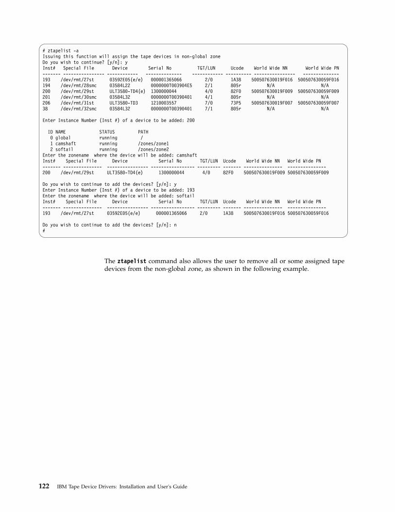
# ztapelist -aIssuing this function will assign the tape devices in non-global zoneDo you wish to continue? [y/n]: yInst# Special File Device Serial No TGT/LUN Ucode World Wide NN World Wide PN------- ---------------- ------------ -------------- ------------ ---------- ---------------- --------------193 /dev/rmt/27st 03592E05(e/e) 000001365066 2/0 1A38 500507630019F016 500507630059F016194 /dev/rmt/28smc 03584L22 0000000T003904E5 2/1 805r N/A N/A200 /dev/rmt/29st ULT3580-TD4(e) 1300000044 4/0 82F0 500507630019F009 500507630059F009201 /dev/rmt/30smc 03584L32 0000000T00390401 4/1 805r N/A N/A206 /dev/rmt/31st ULT3580-TD3 1210003557 7/0 73P5 500507630019F007 500507630059F00738 /dev/rmt/32smc 03584L32 0000000T00390401 7/1 805r N/A N/A
Enter Instance Number (Inst #) of a device to be added: 200
ID NAME STATUS PATH0 global running /1 camshaft running /zones/zone12 softail running /zones/zone2
Enter the zonename where the device will be added: camshaftInst# Special File Device Serial No TGT/LUN Ucode World Wide NN World Wide PN------- --------------- ---------------- ----------------- --------- ------- --------------- ---------------200 /dev/rmt/29st ULT3580-TD4(e) 1300000044 4/0 82F0 500507630019F009 500507630059F009
Do you wish to continue to add the devices? [y/n]: yEnter Instance Number (Inst #) of a device to be added: 193Enter the zonename where the device will be added: softailInst# Special File Device Serial No TGT/LUN Ucode World Wide NN World Wide PN------- --------------- ---------------- ----------------- --------- ------- --------------- ---------------193 /dev/rmt/27st 03592E05(e/e) 000001365066 2/0 1A38 500507630019F016 500507630059F016
Do you wish to continue to add the devices? [y/n]: n#
The ztapelist command also allows the user to remove all or some assigned tapedevices from the non-global zone, as shown in the following example.
122 IBM Tape Device Drivers: Installation and User's Guide

# /opt/IBMtape/ztapelist -dIssuing this function will remove the tape devices from non-global zoneDo you wish to continue? [y/n]: yDo you want to remove the tape devices from all of non-global zones? [y/n]: n
ID NAME STATUS PATH0 global running /1 camshaft running /zones/zone12 softail running /zones/zone2
Enter the zonename where the devices will be removed: camshaftDo you want to remove all of the tape devices from this zone? [y/n]: nInst# Special File Device Serial No TGT/LUN Ucode World Wide NN World Wide PN------- ---------------- ------------- ----------------- ----------- -------- ------------------ -----------------200 /dev/rmt/29st ULT3580-TD4(e) 1300000044 4/0 82F0 500507630019F009 500507630059F009201 /dev/rmt/30smc 03584L32 0000000T00390401 4/1 805r N/A N/A
Enter Instance Number (Inst #) of a device to be removed: 201Removing this tape device /dev/rmt/30smc for this zone camshaft ...Inst# Special File Device Serial No TGT/LUN Ucode World Wide NN World Wide PN------- -------------- ------------------ ---------------- ---------- -------- ------------------- ------------------200 /dev/rmt/29st ULT3580-TD4(e) 1300000044 4/0 82F0 500507630019F009 500507630059F009
Do you wish to continue to remove the devices from this zone? [y/n]: nDo you wish to continue to remove the devices from other zone? [y/n]: y
ID NAME STATUS PATH0 global running /1 camshaft running /zones/zone12 softail running /zones/zone2
Enter the zonename where the devices will be removed: softailDo you want to remove all of the tape devices from this zone? [y/n]: yRemoving all of tape devices for this zone softail ...Inst# Special File Device Serial No TGT/LUN Ucode World Wide NN World Wide PN------- ------------------- --------------- ------------------ --------- -------- -------------- -------------------Do you wish to continue to remove the devices from other zone? [y/n]: n
Configuration parameters
When devices controlled by IBMtape are used, certain device characteristics, suchas the default block size, can be controlled through the device driver configurationfile. The IBMtape configuration file is named IBMtape.conf. The working copy ofthis file is in the /usr/kernel/drv directory.
During installation of IBMtape, the working copy of IBMtape.conf is preserved, ifit exists. During removal of IBMtape, the working copy of IBMtape.conf is notdeleted. These conventions allow configuration settings to remain across updates ofIBMtape. A reference copy of IBMtape.conf with factory default settings is alwaysinstalled in the /opt/IBMtape directory.
Note: IBM requires that the Solaris native SCSI tape device driver `st is configuredso that it does not attempt to support SCSI targets that are controlled by IBMtape.Refer to “Preventing conflicts with other device drivers” on page 108 forinformation about multiple driver access to a device.Attention: Failure to prevent more than one device driver from operating thesame tape drive can cause system panics or data loss on the tape drive.
Configuration settings are applied only at start time, or when IBMtape is unloadedmanually from, then reloaded into, memory. If you change configuration settings inIBMtape.conf, you can make the changes effective by restarting the system. As analternative to restarting, ensure that no IBMtape-owned devices are in use, thenissue the following command.
Chapter 6. Solaris Tape and Medium Changer Device Driver 123

% /opt/IBMtape/tmd -s for IBMtape.4.0.9.2 and later% /usr/sbin/rem_drv IBMtape% /usr/sbin/add_drv -m ’* 0666 bin bin’ IBMtape% /opt/IBMtape/tmd for IBMtape.4.0.9.2 and later
Default settings in IBMtape.conf can be overridden for a particular device (andonly while the device is kept open) with the ioctl application programminginterface (API) of the device driver. The parameter settings that are made throughthe API revert to the default values in IBMtape.conf the next time the device isopened. Refer to the IBM Tape Device Drivers: Programming Reference for informationabout changing configuration parameters under program control.
IBMtape.conf contains one stanza for each SCSI target address/LUN pair that isowned by IBMtape. The reference IBMtape.conf file that is supplied with thepackage contains a stanza for every possible SCSI target and LUN combinationthat is supported by IBM tape systems.
The following example shows the stanza for target 0, LUN 0, with IBMtape'sdefault configuration parameter values. The parameter immediate is disabled,which means that SCSI commands Write FM, Locate, Load-Unload, Erase, andRewind complete before status is returned.name="IBMtape" class="scsi"target=0 lun=0block_size=0buffering=1immediate=0trailer=0sili=0;
The following example shows the stanza for target 0, LUN 0, with IBMtape'sdefault configuration parameter values and the rewind immediate mode set On.This action causes the SCSI rewind command to return control to the applicationprogram before the command completes on the tape drive.name="IBMtape" class="scsi"target=0 lun=0block_size=0buffering=1rew_immediate=1trailer=0sili=0;
If immediate is set to 1 and rew_immediate is set to 0, the setting of rew_immediateis ignored.
The name variable identifies IBMtape as the device driver, and class identifies thetype of device that is supported as SCSI.
The target and the lun variables determine the target address and LUN of IBMdevices that are controlled by that stanza. On systems with multiple SCSI adapters,a single target/LUN stanza controls the configuration settings for all devices thatare addressed with that target address and LUN. Thus, two or more supportedIBM devices on the system that have the same target and LUN settings but areattached to different SCSI buses are all affected by the configuration parameters ofthe single stanza with that target address and LUN.
After installation of the IBMtape package is complete, you can eliminateunnecessary probing for devices by commenting out unused target/LUN pairs. Inthis example, the stanzas for target 0, LUN 0 and target 0, LUN 1 are commented
124 IBM Tape Device Drivers: Installation and User's Guide

out. Those address/LUN combinations are not probed. This action saves timeduring a restart or manual reload of IBMtape. However, if an IBM device isaddressed at target 0, LUN 0 or target 0, LUN 1, it is not detected.#name="IBMtape" class="scsi"#target=0 lun=0#block_size=0#buffering=1#immediate=0#trailer=0#sili=0;
#name="IBMtape" class="scsi"#target=0 lun=1#block_size=0#buffering=1#immediate=0#trailer=0#sili=0;
The remaining five configuration parameters specifically affect the behavior of theIBM device or devices that are associated with that stanza (target and LUN). All ofthese parameters are specific to tape drive device operation only and have noeffect on medium changer device behavior. The default configuration parametersare adequate for most purposes. However, the values in the configuration file canbe modified to suit the specific requirements of the application or the user.
Modifying a value in the configuration file determines the value of the parameterat device open time. When the device is open, the value of a parameter can bealtered with an ioctl function call. But the change is effective only while the deviceremains open. Working configuration parameters revert to the default values(established by the configuration file) when the device is closed and reopened.Refer to the IBM Tape Device Drivers: Programming Reference for information aboutchanging configuration parameters through program control.
Table 25 lists and describes the set of configuration parameters that are recognizedby the IBMtape device driver.
Table 25. Solaris: configuration parameters recognized by IBMtape
Parameter Values Description
block_size (0=variablelength)
This option specifies the device block size that isestablished with the SCSI Mode Select commandduring an open function call. Until this value ischanged, it is the working block size. Variable blocksize is established with a value of zero. Any otherpositive value represents a fixed block size. Themaximum supported block size varies for each tapedevice. Refer to the appropriate hardware referencemanual for information.Note: IBMtape does not allow odd-byte-count fixedblock reads or writes. For instance, a fixed block sizeof 4096 or 4098 is allowed, but 4097 is not. If youattempt to read or write with an odd-byte-count fixedblock size, the read or write returns -1, with errno setto 22, invalid argument. If you must read or writeodd-byte-count blocks, set block size to 0 (variableblock size), then transfer one block’s worth of data perread or write.
Chapter 6. Solaris Tape and Medium Changer Device Driver 125

Table 25. Solaris: configuration parameters recognized by IBMtape (continued)
Parameter Values Description
buffering (0=Off, 1=On) When a Write command is processed, the data is eitherdirectly stored on the physical tape or buffered indevice hardware. Buffering can be turned On and Offwith this option. If buffering is disabled, the effectiveperformance of the device can be degraded seriously.The tape devices cannot take advantage of theirbuffering optimization. Buffer flushing (or committingdata to the tape) can be controlled by the applicationthrough the STIOC_SYNC_BUFFER ioctl function.
immediate (0=Off, 1=On) If immediate is set to 0, the SCSI commands Write FM,Locate, Load-Unload, Erase, and Rewind return withstatus when the command actually completes on thetape drive. If immediate is set to 1, these commandsreturns with status before the command actuallycompletes.
reserve_key (A string of 1-8character ASCIIalphanumerickey such as"key12345". Iffewer than 8characters areused, theremainingcharacters are setto 0x00(NULL).
The user specifies the Persistent Reservation key that isused by the device driver when the PersistentReservation is used.
The reserve key is assigned by the driver by default.
reserve_type (1=reserve(6),2=reserve(10),3=persist_reserve)
This parameter specifies the SCSI Reservation type thatis used by the device driver, either a SCSI Reserve(6)command or a SCSI Persistent Reserve command.The SCSI Reserve(10) command is unsupportedrecently.
The reserve type 1 is set by default.Note: This parameter is not used if the Data PathFailover is supported.
rew_immediate (0=Off, 1=On) If rew_immediate is set to 0, the SCSI Rewindcommand returns with status when the commandactually completes on the tape drive. If it is set to 1,the Rewind command returns with status before thecommand actually completes. If immediate is set to 1,the setting of rew_immediate is ignored.
126 IBM Tape Device Drivers: Installation and User's Guide

Table 25. Solaris: configuration parameters recognized by IBMtape (continued)
Parameter Values Description
trailer (0=Off, 1=On) If a tape drive encounters logical end-of-tape (EOT)during a write operation, it returns a check conditionstatus. The driver returns 0 bytes written to notify theapplication of this EOT situation. A check condition isalso returned by the tape drive for every subsequentwrite operation when past EOT. If trailer is enabled,writing records past EOT is allowed by the devicedriver. Following the first time the write operationnotifies the application of EOT. All subsequent EOTnotifications are suppressed by the driver, and theactual number of bytes written is returned. Whenphysical end of media is reached, all write operationsfail with a return code of -1, regardless of the trailersetting. When trailer is enabled, managing the mediapast EOT is the application’s responsibility.
sili (0=Off, 1=On) Normally, during a read operation, if a larger block ofdata is requested than is read from the tape, the tapedevice raises a check condition. The IBMtape devicedriver must complete error handling procedures,which add overhead to the read operation. TheIBMtape driver does not surface this issue as an errorcondition to the application and ultimately returns theactual number of bytes read. However, this drivererror processing results in less than optimum readperformance in some scenarios. When SILI mode isenabled, the tape device is forced to Suppress IllegalLength Indication during read operations. This actioneliminates the error processing that is run by thedriver and results in improved read performance forsome scenarios. The actual number of bytes read is stillreturned to the application in SILI mode.
max_busy_retry a positiveinteger
When a SCSI command is returned as a BUSY status,IBMtape retries this SCSI command up to 3002 or thisuser-defined time in each interval of 1/10 second.
Dynamic Runtime Attributes
This parameter determines whether dynamic runtime attributes are attempted onopen for supported drives. Default is 1 (On) meaning that the driver automaticallyattempts to set dynamic runtime attributes on open. This action can be changed to0 (Off) in the configuration file before the IBMtape is loaded. It is recommended tokeep dynamic runtime attributes On unless it produces an unexpected problem inthe environment.
The dynamic runtime attributes setting is retained even if the system is rebooted.Follow the steps to enable or disable the Dynamic Runtime Attributes parameter.1. To enable the support on all currently configured devices, add the entry
Dynamic_Runtime_Attribute =1 at the beginning of the IBMtape.conf file.2. Stop the TMD (tape monitor daemon) running on the system and unload the
IBMtape driver module from the current kernel.# /opt/IBMtape/tmd -s# /usr/sbin/rem_drv IBMtape
3. Reload the IBMtape driver module in the kernel and start the daemon.
Chapter 6. Solaris Tape and Medium Changer Device Driver 127

# /usr/sbin/add_drv -m ' 0666 bin bin' IBMtape# /opt/IBMtape/tmd
1. To disable the support on all currently configured devices, add the entryDynamic_Runtime_Attribute = 0 at the beginning of the IBMtape.conf file.
2. Stop the TMD (tape monitor daemon) running on the system and unload theIBMtape driver module from the current kernel.# /opt/IBMtape/tmd -s# /usr/sbin/rem_drv IBMtape
3. Reload the IBMtape driver module in the kernel and start the daemon.# /usr/sbin/add_drv -m ' 0666 bin bin' IBMtape# /opt/IBMtape/tmd
Removing IBMtape
All active processes that use IBM devices that are supported by the IBM SCSI Tapeand Medium Changer Device Driver for Solaris must be stopped for the removalprocedure to complete successfully.
Use the pkgrm command to remove the IBMtape package from the system.% /usr/sbin/pkgrm IBMtape
Adding or removing devices
To add support for a new IBM tape system or to remove support for a previouslyattached IBM tape system, complete the following steps.1. Edit the IBMtape.conf file in the /usr/kernel/drv directory to reflect the
change in IBM device support. Either add a stanza to provide support for adevice that is to be added, or remove (comment out) a stanza for a device thatis no longer supported.
2. When support for a new device is added, ensure that the target and LUNvalues in the configuration file stanza match the target and LUN settings of theIBM device. Refer to “Configuration parameters” on page 123 for informationabout the IBMtape.conf configuration file.
3. Shut down and power Off the host system.4. Plug the new device into the SCSI bus or unplug the existing device from the
bus. Pay particular attention to correct SCSI cabling and termination.5. Power On and start the host system.
Note:
a. It is possible to reinitialize the IBMtape device driver without restarting thesystem. This procedure is done by first unloading the device driver, thenreloading the device driver into kernel memory.
b. For the version of IBMtape.4.0.9.2 and later, the TMD daemon must bestopped. Run the /opt/IBMtape/tmd -s command to unload the IBMtapedriver from the kernel. Running the /opt/IBMtape/tmd command restarts thedaemon afterward to reload the device driver.
The commands to unload the device driver are% /opt/IBMtape/tmd -s for IBMtape.4.0.9.2 and later% /usr/sbin/rem_drv IBMtape
The commands to reload the device driver are% /usr/sbin/add_drv -m ’* 0666 bin bin’ IBMtape% /opt/IBMtape/tmd for IBMtape.4.0.9.2 and later
128 IBM Tape Device Drivers: Installation and User's Guide

When the IBMtape device driver is reloaded, it reads the IBMtape.conf fileand acknowledge changes that are made in the file. This method can be used tomodify configuration parameters.
Note: It is suggested that the host system and all devices that are attached tothe SCSI bus be powered Off before devices are added or removed from theSCSI bus. Hot plugging SCSI devices can cause hardware damage anddisruption of reliable system operation
Unconfiguring tape devices
In some special situations, the user cannot modify IBMtape.conf to unconfiguresome tape devices with IBMtape driver. This issue occurs when more than onedevice is configured with the same target address, or the tape devices are attachedon the FC or SAS HBA running with Oracle HBA driver.
In IBMtape.4.1.9.2 and later, a configuration parameter defined exclude_dev_listis introduced to allow users to exclude some devices from the configuration withIBMtape.
Unconfigure the tape device with the following steps.1. Add the entry of exclude_dev_list in IBMtape.conf in /usr/kernel/drv.
exclude_dev_list=”sn1,sn2,sn3,...” ;
Where: sn is the serial number of the excluded device, 10-characters long forLTO drive, 12-characters long for 359x drive and 16-characters long for changer.The serial number can be found by running the following command./opt/IBMtape/tapelist -l
2. Reinstall IBMtape driver or reboot the system to allow IBMtape to update theconfiguration.
Tapelist Utility Program
A Tapelist Utility Program that is called tapelist is installed in the /opt/IBMtapedirectory as part of the IBMtape package. The tapelist utility provides the user alisting of tape, medium changer, and SAN data gateway devices that areconfigured with the IBMtape driver. It also displays the information of HBA withIBM tape drive attachment and the status of load balancing. The following is anexample of a Tapelist Utility Program output.
Chapter 6. Solaris Tape and Medium Changer Device Driver 129

# tapelistInstance : 697Special File : /dev/rmt/6stDevice : 03592E05(e/e)Serial Number : 000001300168TGT/LUN : 7/0Ucode : 04C4World Wide NN : 5005076302000127World Wide PN : 5005076302400127Dev Phy Path : /devices/pci@1f,2000/QLGC,qla@1/IBMtape@7,0:stPath Type : N/A
# tapelist -thba_index hba_inst hba_driver reg_count usage_count HBA Path--------- -------- ----------- ----------- ----------- --------------------------–0 0 qla2300 4 1 /devices/pci@4,2000/fibre-channel@11 2 lpfc 4 2 /devices/pci@6,2000/pci@1/fibre-channel@42 3 lpfc 1 0 /devices/pci@6,2000/pci@1/fibre-channel@5
A new feature is added in tapelist to display the drive information in the librarythat is running /opt/IBMtape/tapelist -L.
# tapelist -LAddr Inst# Special File Device Serial No TGT/LUN Ucode World Wide NN World Wide PN----- ----- ------------- ------------- --–-------------- ------- ----- ------------–-- ------------–--Library (/dev/rmt/5smc) Info:
2894 /dev/rmt/5smc 03584L22 0000000T003904E5 3/1 806c N/A N/A274 2893 /dev/rmt/13st 03592E05(e/e) 000001365066 3/0 1D10 500507630019F016 500507630059F016276 2914 /dev/rmt/14st 03592E06(e/e) 000001326803 14/0 2444 500507630019F019 500507630059F019
Library (/dev/rmt/7smc) Info:2899 /dev/rmt/7smc 03584L32 0000000T00390401 6/1 806c N/A N/A
265 2898 /dev/rmt/6st ULT3580-TD4(e) 1300000044 6/0 82F0 500507630019F009 500507630059F009
Library 3494 Info:322 /dev/rmt/10st 03592J1A 000001300147 1/0 0464 5005076300000000 5005076300400000
The following is a definition of the fields and headers that appear in the previousscreens.Inst # The instance number of the particular device.Special File The device special file used to access this device.Device A string indicating the device model and encryption information
(e/e: encryption capable/encryption enable).Serial No: The serial number of the device.
TGT/LUN The SCSI target and LUN of the device.Ucode level The current microcode (firmware) loaded on the device.World Wide NN A number indicating Fibre Channel World Wide Node Name of the device.World Wide PN A number indicating Fibre Channel World Wide Port Name of the device.Dev Phy Path A string indicating the device path in the device tree.Path Type A primary or alternate path used for failover.hba_index The index number of the particular HBA in the HBA list.hba_inst The instance number of the particular HBA assigned by the
Solaris system.hba_driver The HBA driver name with IBM tape drive attachment.reg_count The number of IBM tape drives attached on the HBA.usage_count The number of IBM tape drives currently using the HBA.HBA Path A string indicating the HBA device path in the device tree.Addr The element address where the drive is located in the library.e/e The first and second instances of "e" stand for encryption
capable and encryption enable.
The usage of the tapelist program is as follows.
130 IBM Tape Device Drivers: Installation and User's Guide

-l Print for all of the configured devices with the column headers in long list-L Display the tape drives information in the tape library
(IBMtape supported Libraries ONLY)-c Don’t print column headers in long list for all of the configured devices-t Display HBA information and current load balancing status-f Print the list for a particular file only-A List the tape devices by HBA-a Print out the info of all of FC HBAs-h Help menu
Running tapelist without any options displays the device information line by linefor all of the configured devices.
Special files
After the IBMtape driver is installed, a set of special files is available forcompleting input/output (I/O) operations to each supported device. The devicespecial file names that are created by the IBMtape device driver are similar to theSCSI tape special files used on Solaris systems.
Each tape instance has a set of minor numbers that provides access to the samephysical device. But, each minor number provides a different function or behaviorfor the tape subsystem. These minor numbers are accessed through variations ofthe special file name for that device. The special files are created in the /dev/rmtdirectory. These special files are symbolic links to files created within the /devicessubdirectory hierarchy.
Issuing the ls -la /dev/rmt command gives useful information about these devicespecial files. The following example shows entries that are returned by thiscommand for a single IBM tape subsystem. This listing is system-dependent, soentries vary slightly in format, depending on the operating system and SCSIadapter support. Entries might be included for other devices that are notsupported by the IBMtape device driver.lrwxrwxrwx root other 79 Aug 26 18:54 0smc ->/devices/iommu@f,e0000000/sbus@f,e0001000/QLGC,isp@3,10000/IBMtape@2,0:smc
lrwxrwxrwx root other 78 Aug 26 18:54 0st ->/devices/iommu@f,e0000000/sbus@f,e0001000/QLGC,isp@3,10000/IBMtape@2,0:st
lrwxrwxrwx root other 79 Aug 26 18:54 0stb ->/devices/iommu@f,e0000000/sbus@f,e0001000/QLGC,isp@3,10000/IBMtape@2,0:stb
lrwxrwxrwx root other 80 Aug 26 18:54 0stbn ->/devices/iommu@f,e0000000/sbus@f,e0001000/QLGC,isp@3,10000/IBMtape@2,0:stbn
lrwxrwxrwx root other 79 Aug 26 18:54 0stc ->/devices/iommu@f,e0000000/sbus@f,e0001000/QLGC,isp@3,10000/IBMtape@2,0:stc
lrwxrwxrwx root other 80 Aug 26 18:54 0stcb ->/devices/iommu@f,e0000000/sbus@f,e0001000/QLGC,isp@3,10000/IBMtape@2,0:stcb
lrwxrwxrwx root other 81 Aug 26 18:54 0stcbn ->/devices/iommu@f,e0000000/sbus@f,e0001000/QLGC,isp@3,10000/IBMtape@2,0:stcbn
lrwxrwxrwx root other 80 Aug 26 18:54 0stcn ->/devices/iommu@f,e0000000/sbus@f,e0001000/QLGC,isp@3,10000/IBMtape@2,0:stcn
lrwxrwxrwx root other 79 Aug 26 18:54 0stn ->/devices/iommu@f,e0000000/sbus@f,e0001000/QLGC,isp@3,10000/IBMtape@2,0:stn
Chapter 6. Solaris Tape and Medium Changer Device Driver 131

These entries show the device hierarchy that is established to support I/O for anIBM SCSI tape system. The attachment path of the device special files spans fromthe system board, through the S-bus, to the Oracle F/W SCSI adapter (supportedby the QLGC, isp SCSI adapter device driver), to the IBM device at SCSI target 2and LUN 0 (supported by the IBMtape device driver). All nine of these specialfiles are associated with the same IBM device (device number 0).
Device behaviors
Certain device behaviors are determined by which special file in the set is openedfor device access. The smc special file controls only the medium changer portion ofthe device and accepts only medium changer operations by way of the ioctl entrypoint. The smc special file does not support the read and write entry points. Onlyone st type special file for a particular device can be opened at any one time. Thesmc special file can be opened concurrently with any one of the st special files.
The IBMtape device driver decides which types of special files to create duringinstallation, which is based on the IBM device type that is configured. For the IBM3490E Magnetic Tape Subsystem, only the eight st type special files are created. Forother IBM tape drives, all nine special files that are shown previously are created.For IBM tape libraries and autoloaders, only a single smc special file is created.
With the information from the previous command, issuing the ls -la/devices/iommu@f,e0000000/sbus@f,e0001000/QLGC,isp@3,10000 commandpresents further information about the same special files, as shown in the followingexample. Again, the actual path information that is specified in the commandvaries from system to system.crw-rw-rw- 1 bin bin 109,1696 Aug 26 18:54 IBMtape@2,0:smccrw-rw-rw- 1 bin bin 109,1664 Aug 26 18:56 IBMtape@2,0:stcrw-rw-rw- 1 bin bin 109,1728 Aug 26 18:54 IBMtape@2,0:stbcrw-rw-rw- 1 bin bin 109,1732 Aug 26 18:54 IBMtape@2,0:stbncrw-rw-rw- 1 bin bin 109,1688 Aug 26 18:54 IBMtape@2,0:stccrw-rw-rw- 1 bin bin 109,1752 Aug 26 18:54 IBMtape@2,0:stcbcrw-rw-rw- 1 bin bin 109,1756 Aug 26 18:54 IBMtape@2,0:stcbncrw-rw-rw- 1 bin bin 109,1692 Aug 26 18:54 IBMtape@2,0:stcncrw-rw-rw- 1 bin bin 109,1668 Aug 26 18:54 IBMtape@2,0:stn
These entries show the major and minor numbers that are associated with eachspecial file. Here, the major number is 109 and identifies to the system that theIBMtape device driver is in support of these special files. Major numbers areassigned by the system at the time the driver is installed and vary from system tosystem. The nine different minor numbers are specific to the special file names.They are used by the device driver to determine which special file was used toaccess the device and control the device behavior accordingly. For example, theminor number 1696 indicates to the driver that the device was opened by way ofthe smc special file. For information on device special files and major and minornumbers, consult the Solaris mtio man pages.
File naming conventions
Table 26 on page 133 shows the special file naming convention and the associateddevice attributes recognized by the IBMtape device driver.
132 IBM Tape Device Drivers: Installation and User's Guide

Table 26. IBM SCSI Tape/Medium Changer special files for Solaris
Special file nameBSD compatibility (Note
1) Rewind on Close (Note 2) Compression (Note 3)
/dev/rmt/[0–255]smc (Note 4) N/A N/A N/A
/dev/rmt/[0–255]stn (Note 5) No No No
/dev/rmt/[0–255]stcn (Note 5) No No Yes
/dev/rmt/[0–255]st (Note 5) No Yes No
/dev/rmt/[0–255]stc (Note 5) No Yes Yes
/dev/rmt/[0–255]stbn (Note 5) Yes No No
/dev/rmt/[0–255]stcbn (Note 5) Yes No Yes
/dev/rmt/[0–255]stb (Note 5) Yes Yes No
/dev/rmt/[0–255]stcb (Note 5) Yes Yes Yes
Note:
1. The BSD (b) device special file modifies close behavior for non-rewind devices. If the device is opened for norewind on close in non-BSD mode, and if the last command before the device was closed was a read, then thetape is positioned after the filemark immediately following the last block read. If the device is opened for norewind on close in BSD mode, and if the last command before the device was closed was a read, the tape is leftpositioned exactly where it was following the last block read. If the device is opened for rewind on close theBSD mode is not relevant.
2. The no rewind on close (n) device special file does not rewind the tape during a close operation. Otherwise, thetape is rewound when the device is closed. If the last operation before the device was closed was a write orwrite filemark, then enough filemarks is written so that two filemarks follow the data.
For the non-rewind special files, the tapes are positioned between the trailing filemarks before closing. If thedevice is then reopened and more data is written, it is separated by a single filemark from the previous data.
3. The compression (c) device special file determines whether the tape device uses built-in hardware compressionwhile data is stored on the tape. The compression mode of the device can also be set to the wanted stateprogrammatically through the STIOC_SET_PARM ioctl, regardless of the default compression mode that isestablished by the special file that is originally used to open the device.
4. The smc special file is created only for IBM tape systems that provide medium changer capability. For IBM tapelibraries and autoloaders, the smc special file is the only file that is created because the IBMtape device driversupports only the medium changer portion. It does not support the tape drive portion of these devices. For theIBM 3490E Magnetic Tape System, there is no smc special file created.
5. Only one st special file can be opened at one time. The smc special file can be opened by itself or with one ofthe st type files. The smc special file accepts only medium changer commands. Tape drive commands that areissued to the medium changer fail, with errno set to 22, invalid argument.
Aside from the normal configuration with the medium changer that answers as a distinct target/LUN pair, somesupported devices can be configured with a nonstandard integrated medium changer that reports at the sametarget and LUN as the tape drive. In such a case, both st and smc special files accept a limited subset of mediumchanger commands. If you want to use this nonstandard mode, consult the appropriate hardware reference todetermine whether the drive supports such a configuration.
Persistent Naming Support
The device special file names are created by the IBMtape driver in the order thatthe tape devices are presented by the Solaris system. Each device special file nameis maintained with the same logical name across reboots, even when an existingdevice is powered off or not connected.
However, the logical names of devices can be changed because of the swapping ofconnecting cables, HBA mapping changes, tape device driver updates, or otherreasons.
Chapter 6. Solaris Tape and Medium Changer Device Driver 133
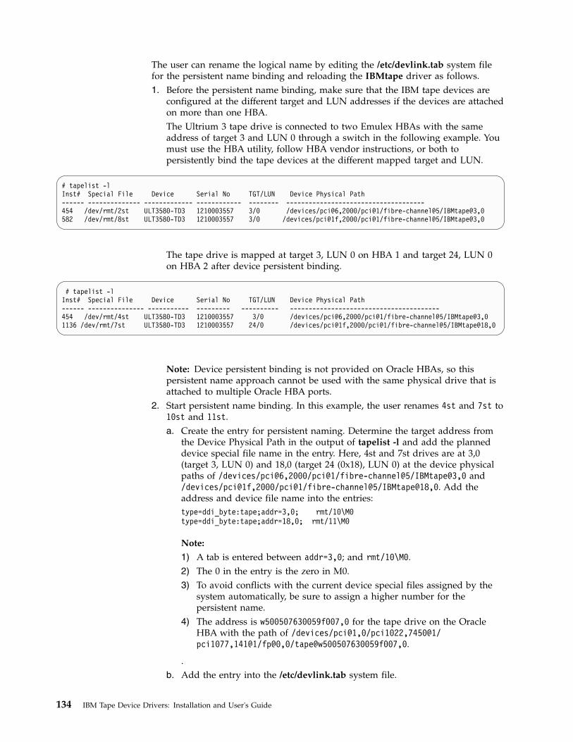
The user can rename the logical name by editing the /etc/devlink.tab system filefor the persistent name binding and reloading the IBMtape driver as follows.1. Before the persistent name binding, make sure that the IBM tape devices are
configured at the different target and LUN addresses if the devices are attachedon more than one HBA.The Ultrium 3 tape drive is connected to two Emulex HBAs with the sameaddress of target 3 and LUN 0 through a switch in the following example. Youmust use the HBA utility, follow HBA vendor instructions, or both topersistently bind the tape devices at the different mapped target and LUN.
# tapelist -lInst# Special File Device Serial No TGT/LUN Device Physical Path------ -------------- ------------- ------------ -------- -------------------------------------454 /dev/rmt/2st ULT3580-TD3 1210003557 3/0 /devices/pci@6,2000/pci@1/fibre-channel@5/IBMtape@3,0582 /dev/rmt/8st ULT3580-TD3 1210003557 3/0 /devices/pci@1f,2000/pci@1/fibre-channel@5/IBMtape@3,0
The tape drive is mapped at target 3, LUN 0 on HBA 1 and target 24, LUN 0on HBA 2 after device persistent binding.
# tapelist -lInst# Special File Device Serial No TGT/LUN Device Physical Path------ --------------- ----------- --------- ---------- ----------------------------------------454 /dev/rmt/4st ULT3580-TD3 1210003557 3/0 /devices/pci@6,2000/pci@1/fibre-channel@5/IBMtape@3,01136 /dev/rmt/7st ULT3580-TD3 1210003557 24/0 /devices/pci@1f,2000/pci@1/fibre-channel@5/IBMtape@18,0
Note: Device persistent binding is not provided on Oracle HBAs, so thispersistent name approach cannot be used with the same physical drive that isattached to multiple Oracle HBA ports.
2. Start persistent name binding. In this example, the user renames 4st and 7st to10st and 11st.a. Create the entry for persistent naming. Determine the target address from
the Device Physical Path in the output of tapelist -l and add the planneddevice special file name in the entry. Here, 4st and 7st drives are at 3,0(target 3, LUN 0) and 18,0 (target 24 (0x18), LUN 0) at the device physicalpaths of /devices/pci@6,2000/pci@1/fibre-channel@5/IBMtape@3,0 and/devices/pci@1f,2000/pci@1/fibre-channel@5/IBMtape@18,0. Add theaddress and device file name into the entries:type=ddi_byte:tape;addr=3,0; rmt/10\M0type=ddi_byte:tape;addr=18,0; rmt/11\M0
Note:
1) A tab is entered between addr=3,0; and rmt/10\M0.2) The 0 in the entry is the zero in M0.3) To avoid conflicts with the current device special files assigned by the
system automatically, be sure to assign a higher number for thepersistent name.
4) The address is w500507630059f007,0 for the tape drive on the OracleHBA with the path of /devices/pci@1,0/pci1022,7450@1/pci1077,141@1/fp@0,0/tape@w500507630059f007,0.
.b. Add the entry into the /etc/devlink.tab system file.
134 IBM Tape Device Drivers: Installation and User's Guide

c. Remove existing links that are created by the IBMtape driver from /dev/rmtby running the # rm command.
d. Run the # devfsadm command without any options to enable IBMtape tocreate the new device special file name as defined in the entries in/etc/devlink.tab. A system reboot is also required if the tape device isattached on Oracle HBA.
e. Run tapelist to list the device special files.
# tapelist -lInst# Special File Device Serial No TGT/LUN Device Physical Path------ ------------- ------------ ------------- ---------- -------------------------454 /dev/rmt/10st ULT3580-TD3 1210003557 3/0 /devices/pci@6,2000/pci@1/fibre-channel@5/IBMtape@3,01136 /dev/rmt/11st ULT3580-TD3 1210003557 24/0 /devices/pci@1f,2000/pci@1/fibre-channel@5/IBMtape@18,0
Control Path failover support for libraries
Configuring and deconfiguring Path Failover support
Control path failover (CPF) support is enabled automatically by default when theIBMtape device driver is installed on Solaris system. The Solaris IBMtape devicedriver provides a driver configuration parameter failover for you to enable ordisable the library control path failover support. To enable the CPF support for allof the paths, no action is required. To disable the CPF support for all of the pathsor a particular path, use the following steps.1. To disable CPF support for all the paths, add and set the failover parameter to
off at the beginning of IBMtape.conf file in the directory of /usr/kernel/drv.2. To disable a particular path, add and set the failover parameter to Off in the
path entry in IBMtape.conf file. For example, name="IBMtape" class="scsi"target=3 lun=1 failover=0;
3. Stop the TMD (tape monitor daemon) from running on the system and unloadthe IBMtape driver module from the current kernel.# /opt/IBMtape/tmd -s
# /usr/sbin/rem_drv IBMtape
4. Reload the IBMtape driver module in the kernel and start the daemon.# /usr/sbin/add_drv -m ' 0666 bin bin' IBMtape
# /opt/IBMtape/tmd
Primary and alternative paths
When the device driver configures a logical device with path failover supportenabled, the first device that is configured always becomes the primary path.When a second or more logical device is configured with path failover supportenabled for the same physical device, it configures as an alternative path. Thedevice driver supports up to 16 physical paths for single a device.
The primary and alternative path information can be obtained in the field of "PathType" running the /opt/IBMtape/tapelist command output and is similar to theexample in Table 27 on page 136.
Chapter 6. Solaris Tape and Medium Changer Device Driver 135

Table 27. Solaris: Example of Control Path failover support command output
#tapelist -1Inst# Special File Device Serial No TGT/LUN Ucode WWNN WWPN Device Physical Path Path Type-------------------------------------------------------------------------------------------------------------686 /dev/rmt/12smc 03584L32 0000000T0039 1/1 402j N/A N/A /devices/pci@If,2000/QLGC,qla@1/IBMtape@1,1 Primary688 /dev/rmt/14smc 03584L32 0000000T0039 2/1 402j N/A N/A /devices/pci@If,2000/QLGC,qla@1/IBMtape@2,1 Alt_path_1694 /dev/rmt/26smc 03584L32 0000000T0039 5/1 402j N/A N/A /devices/pci@If,2000/QLGC,qla@1/IBMtape@5,1 Alt_path_2
The labeling of a logical device as either a primary or alternative path is forinformation only; it is used to1. Identify the actual number of physical devices that are configured on the
system and a specific logical device that is associated with them. Only onelogical device is labeled the primary path for each physical device. However,multiple logical devices can be labeled as an alternative path for the samedevices.
2. Provide information about which logical devices that are configured on thesystem have path failover enabled.
Querying primary and alternative path configuration
You can display the primary and alternative path configuration for all devices withthe tapelist utility.
Note: Display the primary and alternative path configuration for any device byusing tape diagnostic and utility functions. Refer to Chapter 9, “IBM TapeDiagnostic Tool (ITDT),” on page 217.
Disabling and enabling primary and alternative paths
When you install the IBMtape device driver, by default all the available paths for aphysical device are enabled.
Note: Display the primary and alternative path configuration for any device byusing tape diagnostic and utility functions. Refer to Chapter 9, “IBM TapeDiagnostic Tool (ITDT),” on page 217.
Data Path failover and load balancing support for tape drives
Note: The tape drive failover feature code must be installed before the DPF forIBM Ultrium tape drive is enabled in the Solaris IBMtape device driver. Refer to“Automatic failover” on page 5 to determine which feature code is required foryour machine type.
Configuring and deconfiguring Path Failover support
Path failover support for tape drives is enabled automatically when the devicedriver with the version of IBMtape.4.2.1.0 or later is installed. It is disabled bydefault at the previous version. When path failover support is enabled for a logicaldevice, it remains set until the device is deleted or the support is deconfigured.The path failover setting is retained even if the system is rebooted. Path failoversupport can be enabled on all configured devices at one time, or it can be enabled
136 IBM Tape Device Drivers: Installation and User's Guide

or disabled selectively by logical device. It might be desirable at times to configuresome, but not all, logical paths to a device with the support enabled. Follow thesteps to enable the DPF support:1. To enable the support globally on all currently configured devices, add an entry
of dpf_support=1 at the beginning of the IBMtape.conf file, such asdpf_support=1;
2. Or, to enable a particular path, add the parameter dpf_support and turn it onin the path entry in the IBMtape.conf file. For example,name="IBMtape" class="scsi" target=3 lun=0 dpf_support=1;
3. For the IBM Ultrium tape drive, you must enter the DPF feature keys in theparameter dpf_keys at the beginning of the IBMtape.conf file in the directory/usr/kernel/drv. For example,dpf_keys="A729E60F7B119411, C7A0B9ef2c1a4360, a729e60f7b118460";
Note:
a. The parameter dpf_keys is in the format “key1, key2, key3, ...... ”. Each keyis 16 characters long with a comma "," and a space " ". The IBMtape driversupports up to 36 dpf keys.
b. DPF keys do not need to be added in IBMtape.conf if you are running thelatest drive code on Ultrium 3 and Ultrium 4 drives.
4. Stop the TMD (tape monitor daemon) running on the system and unload theIBMtape driver module from the current kernel.# /opt/IBMtape/tmd -s# /usr/sbin/rem_drv IBMtape
5. Reload the IBMtape driver module in the kernel and start the daemon.# /usr/sbin/add_drv -m ’ 0666 bin bin’ IBMtape# /opt/IBMtape/tmd
This action deconfigures all devices to add the parameter dpf_support=0 in theIBMtape.conf file, and reboot the system or deconfigure and reconfigure alldevices. For example,1. To disable the support globally on all currently configured devices, add the
entry dpf_support=1 at the beginning of the IBMtape.conf file.# dpf_support=0;
2. Stop the TMD (tape monitor daemon) from running on the system and unloadthe IBMtape driver module from the current kernel.# /opt/IBMtape/tmd -s# /usr/sbin/rem_drv IBMtape
3. Reload the IBMtape driver module in the kernel and start the daemon.# /usr/sbin/add_drv -m ’ 0666 bin bin’ IBMtape# /opt/IBMtape/tmd
To disable the support on a single logical device, follow these steps.1. To enable the support globally on all currently configured devices, add an entry
dpf_support=1 at the beginning of the IBMtape.conf file, such asdpf_support=1;
2. To disable a particular path, add the parameter dpf_support and turn it off inthe path entry in the IBMtape.conf file. For example,name="IBMtape" class="scsi" target=3 lun=0 dpf_support=0;
3. Stop the TMD (tape monitor daemon) running on the system and unload theIBMtape driver module from the current kernel.
Chapter 6. Solaris Tape and Medium Changer Device Driver 137

# /opt/IBMtape/tmd -s# /usr/sbin/rem_drv IBMtape
4. Reload the IBMtape driver module in the kernel and start the daemon.# /usr/sbin/add_drv -m ’ 0666 bin bin’ IBMtape# /opt/IBMtape/tmd
Primary and alternative paths
When the device driver configures a logical device with path failover supportenabled, the first device that is configured always becomes the primary path.When a second logical device is configured with path failover support enabled forthe same physical device, it configures as an alternative path. A third logical deviceis configured as the next alternative path, and so on. The device driver supportsup to 16 physical paths for a single device.
For example, if 0st (port 0 of 3592) is configured first, then 5st (port 1), 18st (port1), and 21st (port 0) to the two HBAs through a switch (here, WWPN5005076302400127 from port 0 and 5005076302800127 from port 1), the/opt/IBMtape/tapelist command output is similar to the example in Table 28.
Table 28. Example of Data Path failover support command output
#tapelist -1Inst# Special File Device Serial No TGT/LUN Ucode WWNN WWPN
Device Physical Path Path Type--------------------------------------------------------------------------------------------------685 /dev/rmt/0st 03592J1A 000001300168 1/0 04CE 5005076302000127 5005076302400127/devices/pci@1f,2000/QLGC,qla@1/IBMtape@1,0 Primary
697 /dev/rmt/5st 03592J1A 000001300168 7/0 04CE 5005076302000127 5005076302800127/devices/pci@1f,2000/QLGC,qla@1/IBMtape@7,0 Alt_path_1
666 /dev/rmt/18st 03592J1A 000001300168 1/0 04CE 5005076302000127 5005076302800127/devices/pci@1f,4000/JNI,FCR@2/IBMtape@1,0 Alt_path_2
670 /dev/rmt/21st 03592J1A 000001300168 3/0 04CE 5005076302000127 5005076302400127/devices/pci@1f,4000/JNI,FCR@2/IBMtape@3,0 Alt_path_3
The labeling of a logical device as either a primary or alternative path is forinformation only, to1. Be able to identify the actual number of physical devices that are configured on
the system and a specific logical device that is associated with them. Only onelogical device is labeled the primary path for each physical device. However,many (multiple) logical devices might be labeled as an alternative path for thesame devices.
2. Provide information about which logical devices configured on the system havepath failover support enabled.
Querying primary and alternative path configuration
You can display the primary and alternative path configuration for all devices withthe tapelist utility.
Note: Display the primary and alternative path configuration for any device byusing tape diagnostic and utility functions. Refer to Chapter 9, “IBM TapeDiagnostic Tool (ITDT),” on page 217.
138 IBM Tape Device Drivers: Installation and User's Guide

Disabling and enabling primary and alternative paths
When you enter the parameter dpf_support in the IBMtape.conf file and install theIBMtape device driver, all the available paths for a physical device are enabled.1. Add the parameter of dpf_support and turn it off in the path entry in
IBMtape.conf file. For example,name="IBMtape" class="scsi" target=3 lun=0 dpf_support=0
2. Stop the TMD (tape monitor daemon) from running on the system and unloadthe IBMtape driver module from the current kernel.# /opt/IBMtape/tmd -s # /usr/sbin/rem_drv IBMtape
3. Reload the IBMtape driver module in the kernel and start the daemon.# /usr/sbin/add_drv -m ' 0666 bin bin' IBMtape# /opt/IBMtape/tmd
To enable a path from a disabled state, you can run the following steps.1. Add the parameter of dpf_support and turn it off in the path entry in
IBMtape.conf file. For example,name="IBMtape" class="scsi" target=3 lun=0;
2. Stop the TMD (tape monitor daemon) from running on the system and unloadthe IBMtape driver module from the current kernel.# /opt/IBMtape/tmd -s# /usr/sbin/rem_drv IBMtape
3. Reload the IBMtape driver module in the kernel and start the daemon.# /usr/sbin/add_drv -m ' 0666 bin bin' IBMtape# /opt/IBMtape/tmd
System-managed encryption
Device driver configuration
System-Managed Encryption can be set on global or a specific tape drive inIBMtape.conf in /usr/kernel/drv. There are two new configuration parametersadded for encryption.v sys_encryption_proxy “ON/OFF” Use System Encryption FCP Proxy Managerv sys_encryption_write “OFF/ON/CUSTOM” System Encryption for Write
Commands at BOP
The sys_encryption_proxy parameter enables device driver system-managedencryption for a tape drive by setting the value to ON (default set).
The sys_encryption_write parameter controls if the device driver can set the tapedrive to encryption enabled for write commands. When set to OFF, the tape driveuses encryption for read operations; write operations do not use encryption. Whenset to ON, the tape drive uses encryption for both read/write operations. When setto CUSTOM, the device driver does not modify current tape drive setting. Thecustom setting is intended for applications by using system-managed encryption tocontrol write encryption without device driver intervention. The parameter is set to“CUSTOM” by default.
Note: If sys_encryption_write is set to ON, an application cannot open a tapedrive by using the append mode.
Chapter 6. Solaris Tape and Medium Changer Device Driver 139

To make a global setting to enable SME in IBMtape.conf:sys_encryption_write=1; # System Encryption for Write Commands at BOP
To enable SME for a particular targetv name="IBMtape"v class="scsi"v target=0v lun=0v block_size=0v buffering=1v immediate=0v trailer=0v sili=0v sys_encryption_write=1;
To disable SME in a particular targetv name="IBMtape"v class="scsi"v target=0v lun=0v block_size=0v buffering=1v immediate=0v trailer=0v sili=0v sys_encryption_proxy=0;
Querying tape drive configuration
Querying tape drive configuration is a tape diagnostic and utility function. Refer toChapter 9, “IBM Tape Diagnostic Tool (ITDT),” on page 217.
Testing data encryption configuration and connectivity
A data encryption test is available to validate the ibmekm.conf file server entriesand test tape drive to server connectivity operations.
This test is a tape diagnostic and utility function. Refer to Chapter 9, “IBM TapeDiagnostic Tool (ITDT),” on page 217.
Field support information
When encryption failures require field support or development analysis, run the/opt/IBMtape/diags_info script to generate a file of diags.out. Tape drive dumpsand EKM server logs might be needed in addition to this information.
140 IBM Tape Device Drivers: Installation and User's Guide

Problem determination
The following sections describe the service and diagnostic aids that are part of theIBM SCSI Tape and Medium Changer Device Driver for Solaris package.Procedures for verifying correct installation of the device, basic problemdetermination guidelines, and outlines of the utility program included with theIBMtape package are included.
Functional verification
If you wish to verify that the installation of the IBM SCSI Tape and MediumChanger Device Driver for Solaris package was successful, follow these steps.1. Enter this command to verify that installation was successful.
/usr/bin/pkginfo IBMtape
The following information must be displayed.system IBMtape IBM SCSI Tape & Medium Changer Device Driver x.x.x.xwhere x.x.x.x is the version of the device driver.
2. To verify that device driver support for a specific IBM tape system that isattached to the system is functioning correctly, enter the following command./opt/IBMtape/tapelist -f /dev/rmt/nst
substituting for n the number that is associated with the device special fileassigned to the IBM tape system that you want to check. Listing the contents ofthe /dev/rmt directory (by using the ls command) can be helpful indetermining the correct special file name. For medium changer devices, thespecial file name /dev/rmt/nsmc must be used.The following information is displayed.IBM Tape Device Information :
Instance : 202Special File : /dev/rmt/13st
Device : ULT3580-TD5(fh)Serial Number : 1013000306
TGT/LUN : 5/0Ucode : z1B8
World Wide NN : 500507630019F00BWorld Wide PN : 500507630059F00BDev Phy Path : /devices/pci@6,2000/fibre-channel@1/IBMtape@5,0
Path Type : N/APath Type : N/A
3. To verify that the IBMtape device driver is loaded in kernel memory, enter thefollowing command./usr/sbin/modinfo | /usr/bin/grep IBMtape
The following information is displayed.165 f5f10000 15c0s 109 1 IBMtape (IBM SCSI Tape/Medium Changer DD)
The first five fields that are shown probably do not match your specific output.The fields indicate the ID, load address, size, major number, and revision for theIBMtape device driver and vary from machine to machine
Sense data logging
When the tape drive responds with a CHECK CONDITION status and associatedsense keys of 0x1 (Recovery Error), 0x3 (Medium Error), 0x4 (Hardware Error), and
Chapter 6. Solaris Tape and Medium Changer Device Driver 141

0xB (Aborted Command) for a hardware or medium error, the sense data is loggedin to the system log file (typically /var/adm/messages).
Installation problems
If you are experiencing problems with installation of the IBM SCSI Tape andMedium Changer Device Driver for Solaris package, the following informationmight help. If you cannot solve the problems after the following is checked, contactthe appropriate IBM service representative.v If you receive the following message during installation,
drvconfig: System call ’modctl_modconfig’ failed:No such device or address.
Warning: Driver (IBMtape) configuration failed.System could not install driver.
it indicates that the IBMtape device driver was not loaded because it did notdetect the presence of any supported IBM devices on the SCSI bus. Verify thatSCSI adapter device driver support is installed and configured correctly. Verifythat the IBM tape subsystem is connected properly to the SCSI bus, which ispowered On, and online. It is not necessary for the tape drive to have acartridge that is loaded to be recognized by the IBMtape device driver.
v If you cannot open an IBM device, verify that you are using the correct specialfile. The IBM tape special files are of the form *st* in the /dev/rmt directory. TheIBM medium changer special files are of the form *smc in the /dev/rmtdirectory. Ensure that the Solaris native tape device driver (st) is not contendingfor the same IBM device. Consult the st.conf file in the /kernel/drv directoryand comment out conflicting stanzas.
Tape monitor daemon (tmd)
The Tape Monitor Daemon is introduced in the version of IBMtape.4.0.9.2 or later.It is designed to run concurrently with the IBMtape driver. It automaticallyretrieves and stores the IBM tape drive diagnostic information (drive dump) intothe /var/opt/IBMtape directory. The daemon is automatically started when thedriver is installed, even when no tape device is attached on the system. An entryname="IBMtape" parent="pseudo" instance=16383; is also entered into theconfiguration file of /usr/kernel/drv/IBMtape.conf automatically for the daemonduring the IBMtape driver installation.
The following options can be used to configure the tape monitor daemon, runningit on the command line. Most options can also be specified in the /etc/tmd.confconfiguration file. However, the command line options override any configurationfile options.-s Stop any currently running instance of the tape monitor daemon.-r Restart the tape monitor daemon and reload all configuration settings.-d Turn on drive error diagnostic retrieval and storage.
This option is enabled by default.-D Turn off drive error diagnostic retrieval and storage.-p <directory> Specify an alternate directory for the storage of
drive diagnostic information. Default directory is /var/opt/IBMtape-l <filename> Specify a file for writing daemon related log messages.
By default, the tmd only writes status information to the syslog file of/var/adm/messages.
-y Turns off writing log messages to syslog.-z Turn off compression. By default, the tmd will use a form of file compression
to reduce the size of stored diagnostic information.
142 IBM Tape Device Drivers: Installation and User's Guide

The file name of dump presents some useful information. An example of the dumpfile isIBMtape.000001300148.2004-04-09-14:54:14.dump.gz
Here, 000001300148 represents the serial number of the tape device,2004-04-09-14:54:14 is the time stamp for the dump retrieval.
A message is also logged in the syslog file of /var/adm/messages after a drivedump is retrieved by tmd. For example,Apr 9 14:54:21 Java tmd[3279]: Drive dump saved to /var/opt/IBMtape
IBMtape.000001300148.2004-04-09-14:54:14.dump.
Tracing facility
IBMtape incorporates a tracing facility that is useful for completing problemdetermination. The tracing facility logs diagnostic information to/var/adm/messages based on the control variable IBM_trace. Refer to “Setting theIBM_trace level for static tracing” on page 145 for instructions on how to set thetrace value.
IBM_trace values range from 0-13 and result in posted messages as shown inTable 29. Postings are cumulative, so trace level 3 also posts items for levels 2, 1,and 0. A trace value of 2 or 3 is suitable for most normal production environments,with little or no degradation of throughput. IBM_trace values of 4 and higherincreasingly degrade performance and generally is used only when directed byIBM support personnel.
Table 29. Solaris: tracing facility
Trace level Items traced
0 Severe error conditions only. For installations with small /var file systems,this setting can prevent filling the file system unexpectedly. However, thissetting might be at the cost of not recording messages that are related toserious device or system environment errors.
1 Device sense data. Sense data can help in diagnosing the source ofunexpected error conditions.
3 Device opens and closes,
Decoded SCSI command, sense key, ASC and ASCQ for sense data.
4–13 Increasingly verbose tracing information. These tracing levels are useful onlyto IBMtape developers.
Note: IBMtape earlier than Version 4.0.2.7 had only IBM_trace values 0–4. Message contentand selection differed significantly from current IBMtape versions.
By default, system error messages, including IBMtape trace messages, are placedin /var/adm/messages. If your installation modified /etc/syslog.conf to redirectsystem error messages, IBMtape tracing is handled as other kernel messages. Referto the syslog.conf man page and the comments in syslog.conf for informationabout the system logging operation. Changes made to syslog.conf take effect afterthe next system restart.
The following shows trace level 2 output, with system date and time stampsremoved. Device instance 390 is opened on the first line. The device minor number12450 is decoded and shows that the SCSI medium changer (smc) special file wasopened.
Chapter 6. Solaris Tape and Medium Changer Device Driver 143

The second line decodes selected fields from the sense data that follows it. Thedecoded information shows that sense data was generated during a Move Mediumcommand. Looking up the decoded Sense Key/ASC/ASCQ combination in the3590 hardware reference, we find that the command failed because the move fromlocation was empty. The actual sense data follows the decoded fields.
Note: Solaris, rather than printing multiple 16-byte lines of hexadecimal zeros,prints only the first such line, followed by a repeat count.IBMtape(390) _open: 374 Inst 390, Minor 12450 (smc), Flags 0x5,
TL 2/0/0, 4.0.2.8IBMtape(390) check_sense: cmd 0xa5(move_medium), key/asc/ascq 0x5/3b/e,
defer 0, retry 0, rc 22IBMtape(390) 03590B11 SENSE DATA:IBMtape(390) 70 0 5 0 0 0 0 58 0 0 0 0 3b e ff 2IBMtape(390) 0 20 1 40 a 9 1 0 0 0 0 0 0 0 a5 0IBMtape(390) 0 0 0 0 0 0 0 0 0 0 0 0 0 0 0 0last message repeated 1 timeIBMtape(390) 0 0 0 0 0 0 0 0 36 33 39 20 20 20 20 0IBMtape(390) 0 0 0 0 0 0 0 0 0 0 0 0 0 0 0 0IBMtape(390) _close: Inst 390, Minor 12450 (smc), Flags 0x5, exit(0)
In the next example, the device open line shows that a tape drive (drv) devicespecial file was opened. The sense data for device instance 292 was generatedduring a space operation. The Sense Key/ASC/ASCQ shows that a filemark wasencountered during the space.IBMtape(292) _open: 554 Inst 292, Minor 9412 (drv), Flags 0x5,
TL 2/0/0, 4.0.2.8IBMtape(292) check_sense: cmd 0x11(space), key/asc/ascq 0x0/0/1,
defer 0, retry 0, rc 5IBMtape(292) 03570B02 SENSE DATA:IBMtape(292) f0 0 80 0 0 0 1 48 0 0 0 0 0 1 ff aIBMtape(292) c4 b1 0 20 0 5 1 91 0 34 0 0 0 0 11 0IBMtape(292) 0 0 0 0 0 0 0 0 0 0 0 0 0 0 0 6IBMtape(292) 6f 28 0 ad 73 32 0 0 0 0 0 0 0 0 0 0IBMtape(292) 0 0 0 0 0 0 20 0 31 42 41 20 20 20 20 0IBMtape(292) _close: Inst 292, Minor 9412 (drv), Flags 0x5, exit(0)
Finally, the sense data for device instance 230, a tape drive, occurred during a testunit ready and indicates that no tape is loaded in the drive.IBMtape(230) _open: 728 Inst 230, Minor 7366 (drv), Flags 0x5,
TL 2/0/0, 4.0.2.8IBMtape(230) check_sense: cmd 0x0(test_unit_ready),
key/asc/ascq 0x2/3a/0, defer 0, retry 0, rc 5IBMtape(230) 03570B02 SENSE DATA:IBMtape(230) 70 0 2 0 0 0 0 48 0 0 0 0 3a 0 ff 2IBMtape(230) c4 8 0 30 0 6 1 40 0 0 0 0 0 0 0 0IBMtape(230) 0 0 0 0 0 0 0 0 0 0 0 0 0 0 0 0last message repeated 1 timeIBMtape(230) 0 0 0 0 0 0 0 0 31 42 41 20 20 20 20 0IBMtape(230) _close: Inst 230, Minor 7366 (drv), Flags 0x5, exit(0)
You can match an instance number with its corresponding device special file intwo steps.1. Find the instance number in /etc/path_to_inst.
$ grep 292 /etc/path_to_inst"/pci@6,4000/scsi@2,1/IBMtape@2,0" 292 "IBMtape"
2. List long the contents of /dev/rmt and search for the path name you found inthe previous step.
144 IBM Tape Device Drivers: Installation and User's Guide

$ ls -l /dev/rmt | grep "/pci@6,4000/scsi@2,1/IBMtape@2,0"lrwxrwxrwx 1 root other 48 Aug 26 11:49 8st ->
../../devices/pci@6,4000/scsi@2,1/IBMtape@2,0:stlrwxrwxrwx 1 root other 49 Aug 26 11:49 8stb ->
../../devices/pci@6,4000/scsi@2,1/IBMtape@2,0:stb
In this example, /dev/rmt/8st, /dev/rmt/8stb, and so on, are symbolic links to thedevice special files that are associated with device instance 292.
Dynamic tracing utility
A dynamic tracing utility named tapedtrc is introduced in the IBMtape.4.1.6.0 orlater driver. It is used to dynamically set, reset, start, stop, and query IBMtapetracing at any time for debugging use. The program is in the/opt/IBMtapedirectory, with the tracing level set to 0 by default.
Use the tapedtrc program from the command line as follows.
/opt/IBMtape/tapedtrc [option]options:
[set] - Set IBMtape trace level and/or start the tracing[set] level - Set trace to a particular trace level[get] - Query the current IBMtape trace level[start] - Start IBMtape tracing[stop] - Stop IBMtape tracing without the trace level reset[clean] - Stop the IBMtape tracing and reset IBMtape trace
level to 0[help] - IBM tapedtrc help menu
Setting the IBM_trace level for static tracing
The user can still enable or disable static IBMtape tracing and set the IBM tracelevel in /etc/system or run the adb system command. The host is required to rebootto enable or disable the tracing when the trace level is set in /etc/system. TheIBMtape driver must be loaded in the kernel. If the tracing is enabled or disabledby using the adb command, the tracing starts or stops at the next device open.
The default value for IBM_trace is zero (0). You can define another IBM_trace valueby placing an entry in /etc/system so that IBM_trace is set at each restart. Forexample, this entry in /etc/system sets IBM_trace to 2 at each restart.set IBMtape:IBM_trace = 2
When IBM_trace is set in /etc/system, it affects tracing during driver loading,initialization, and operation.
You can also set or modify the IBM_trace value manually in an adb session.Because the driver must already be loaded and initialized before this method isused, the trace value that is set is active only during driver operation.
In this sample session, ksh> is a shell prompt, and adb> is the adb session prompt.Commands that you enter are in boldface. Explanatory comments follow numbersigns (#) or exclamation and number sign pairs (!#). Text lines without a prefix areadb session responses to commands.## Start adb session and set session prompt.ksh> adb -P "adb> " -k -w /dev/ksyms /dev/memphysmem 7c5e!#
Chapter 6. Solaris Tape and Medium Changer Device Driver 145
!# Set default for input values to base 10.adb> a$dradix=10 base ten!#!# Display current IBM_tape value as unsigned decimal integer.adb> IBM_trace/uIBM_trace:IBM_trace: 0!#!# Set new IBM_trace value.!# adb will confirm the old and new values.adb> IBM_trace/w 2IBM_trace: 0 = 2!#!# Quit session.adb> $q## Back to the shell.ksh>
Running the diags_info script
Run the diags_info script in the /opt/IBMtape directory. This script detects theproblems on the configuration files, gathers important system HBAs, andconfiguration information. The script must be run as root. If not run as root, theinformation must be labeled as such, but the value of the information is degradedwhen run as a non-root user.
To facilitate capture of data, the script places information in a file that is calleddiags.out in the directory where the script is. Send the output file to the locationidentified by your IBM service representative.
iostat command
IBMtape driver supports the iostat system command, which reports I/O statisticsfor the supported tape drives in IBMtape.4.1.2.7 and later versions. Refer to man(1M) iostat for the command usage.
Reservation conflict logging
When the device driver receives a reservation conflict during open or after thedevice is opened, it logs a reservation conflict in the Solaris system log of/var/adm/messages. Before the error is logged, the device driver issues aPersistent Reserve In command to determine whether a SCSI PersistentReservation is active on the reserving host. It gets the reserving host initiatorWWPN (worldwide port name) and reserve key. If successful, the device driverlogs this information in the detail data. After the reserving host WWPN is logged,subsequent reservation conflicts from the same reserving host WWPN andreservation key are not logged. This action prevents multiple entries in the systemlog until either the reserving host WWPN or reservation key is different from theone initially logged. Or, the device driver reserved the device and then anotherreservation conflict occurs.
The log examples1. The information is logged when the drive is reserved with a Persistent
Reservation.log_reserve: Reserving host key 46E48C49413E6EB1 WWPN 210000E08B118BB1
146 IBM Tape Device Drivers: Installation and User's Guide

2. The information is logged when the drive is reserved with an SCSI-2 Reserve.log_reserve: Reservation Conflict: read full status failure (rc 16)
3. The information is logged when the drive is reserved but the host reservationinformation is not available.log_reserve: Reservation Conflict: No reserving host information is available.
Note: To disable reservation conflict logging, add the entry log_reserve = 0 at thebeginning of IBMtape.conf, then reload the Tape Monitor Daemon and the driver.
Chapter 6. Solaris Tape and Medium Changer Device Driver 147
||

148 IBM Tape Device Drivers: Installation and User's Guide

Chapter 7. Windows Tape and Medium Changer device driver
This chapter describes the hardware requirements, software requirements, andinstallation notes for the Microsoft Windows device drivers for IBM tape devices.
Purpose
The Windows tape and medium changer device driver is designed to takeadvantage of the features that are provided by the IBM tape drives and mediumchanger devices. The goal is to give applications access to the functions requiredfor basic tape operations (such as backup and restore) and medium changeroperations (such as mount and unmount the cartridges), and to the advancedfunctions needed by full tape management systems. Whenever possible, the driveris designed to take advantage of the device features transparent to the application
Data flow
The software that is described here covers the Windows device driver and theinterface between the application and the tape device.
Figure 14 illustrates a typical data flow process.
Product requirements
Hardware requirements
Refer to the “Hardware requirements” on page 1 for the latest hardware that issupported by the IBM tape device driver.
Software requirements
For current software requirements, refer to the “Software requirements” on page 1.
Note: Limited support for customers who have Microsoft Windows Server 2008extended support from Microsoft only.
Installation and configuration instructions
This section includes instructions for installing and configuring the Windows tapeand medium changer device driver on Windows Server 2012.
The recommended procedure for installing a new version of the device driver is touninstall the previous version (see “Uninstalling the device drivers” on page 153).
ApplicationProgram
Windows Tapeand Medium
Changer DeviceDriver
Host BusAdapterDriver
TapeDevice
a2500268
Figure 14. Data flow for Windows device driver (IBMmag)
© Copyright IBM Corp. 2007, 2015 149
||

Windows Server 2012 instructions
This section describes how to install, remove, and uninstall the Windows tape andmedium changer device drivers on Windows Server 2012.
Installation overview
The installation process consists of the following steps:1. Verify that the hardware and software requirements are met.2. Install the host bus adapters and drivers.3. Shut down the system.4. Connect the tape and medium changer devices to the host bus adapters.5. Power on the tape and medium changer devices.6. Restart the system.7. Log on as Administrator.8. Install and configure the devices and device drivers with the installation
application.
Installation procedures
These procedures make the following assumptions:v No other driver is installed that claims the tape and medium changer devices.v If you are updating the device driver from a Microsoft certified version to an
uncertified version, you must first uninstall the certified driver. Refer to“Uninstalling the device drivers” on page 153.
v The host bus adapter is installed, configured properly, and is running supportedmicrocode and driver levels.
v Device drivers are installed on Windows Server 2012 or 2012R2, with V6.2.5.3 orlater.
v Different registry keys are created to configure different parameters. They can beat System\CurrentControlSet\Services\ and the subkeys are created dependingon the Windows Server version. In the case of Windows Server 2012 they are– ibmcg2k12– ibmtp2k12– ibmtpbs2k12
Refer to this list when in doubt of the registry key's name and instructions thatinvolve modifying the registry. Caution and a backup is advised due to theregistry's nature.
v Drivers are identified by the following conventions, where nnnn refers to aversion of the driver. If there is more than one version, use the latest.– Windows Server 2012 for extended 64-bit architectures (Intel EM64T and
AMD64),IBMTape.x64_w12_nnnn.zip
To install the device drivers, follow this procedure.1. Log on as Administrator.2. Download the appropriate driver. Refer toAppendix A, “Accessing
documentation and software online,” on page 327.3. Extract the driver package to a hard disk drive directory of your choice, other
than the root directory.
150 IBM Tape Device Drivers: Installation and User's Guide
||
|||
|
|
|
|||

4. Ensure that the tape and medium changer devices are connected to your hostbus adapter and configured properly by locating the devices in DeviceManager.
5. Double-click either install_exclusive.exe or install_nonexclusive.exe.v install_exclusive.exe The driver issues automatic reserves on open. It also
prevents multiple open handles from the host to a drive from existing at thesame time, as is required by applications such as Tivoli Storage Manager.This driver is also required for the failover feature to work as it usespersistent reservation (by default).
v install_nonexclusive.exe The driver permits open handles from the host to adrive to exist at the same time, as is required by applications such asMicrosoft Removable Storage Manager (RSM) or Microsoft Data ProtectionManager (DPM).
Note:
a. More installation features are available through the command-line interface(CLI), which includev Installing only the tape or medium changer device drivers (-t or -c)v Running in debug mode, which creates the file debug.txt in the driver
package directory (-d)v Running in silent mode, which suppresses messages that require user
intervention, but only with Microsoft-certified IBM drivers (-s)v Disabling the Microsoft RSM service (-r), available in driver packages
v6.1.8.6 and later
a2500267
Figure 15. Installation application in Windows Explorer
Chapter 7. Windows Tape and Medium Changer device driver 151

v Disabling DPF from installation (-f), available in driver packages v6.2.0.1and later
v Enabling Persistent Reserve from installation if DPF is disabled (-p),available in driver packages v6.2.0.6 and later.
v Disable Media Polling (-m).v Disable Dynamic Runtime Attributes (-a).v Exclude devices from being claimed by the driver (-e), available in driver
packages v6.2.5.3 and later.
To install the device drivers with any of these features, instead ofdouble-clicking the installation executable file, open a command-linewindow and cd to the driver package directory. For the usage information,type install_exclusive.exe -h or install_nonexclusive.exe -h at theprompt.
b. If the Windows "Found New Hardware" Wizard begins during installation,cancel the wizard. The installation application completes the necessarysteps.
6. If you are installing a Windows Server 2012 driver that is not certified by theMicrosoft Windows Hardware Quality Laboratories (WHQL), it likely has aVeriSign digital signature. During installation, you might be presented with aprompt to install the software. Mark the Always trust software from IBMCorporation check box and click Install. You see this screen the first time thatyou install the drivers, provided you click the Always trust software box.
Note: All drivers that are released by IBM went through a complete test toensure that they are stable and conform to specified requirements.
7. To verify that the tape and medium changer devices and drivers are installedcorrectly, follow the instructions in Appendix B, “Verifying correct attachmentof your devices,” on page 331.
Device removal or disable procedure
If you must remove a device, or if you are altering the hardware configuration,you must uninstall or disable the device first.1. Right-click My Computer, select Manage to open the Computer Management
Console, and click Device Manager.2. Right-click the device that you want to uninstall and select Uninstall .... If you
want to disable the device without uninstalling it, you can select Disable.
a2502
15
Figure 16. Windows logo testing screen
152 IBM Tape Device Drivers: Installation and User's Guide
||

3. You are prompted to confirm the uninstallation. Click OK.4. In Device Manager, under System devices, right-click Changer Bus
Enumerator and select Uninstall.5. In Device Manager, under System devices, right-click Tape Bus Enumerator
and select Uninstall.
Note: This removal procedure removes the device from the device tree, but it doesnot uninstall the device driver files from your hard disk.
Uninstalling the device drivers
To uninstall the device drivers from the system, which includes deleting the systemfiles and deallocating other system resources, complete the following steps.1. Quiesce all activity on the tape and medium changer.2. Double-click uninst.exe in the driver package.
Note: This action removes all the files in the system directories that werecreated during the installation of the device driver. It does not delete thecompressed file or the files that were extracted from the compressed file. If youwant to remove these files, you must delete them manually. For v.6.2.5.3 andlater, it is not required to manually remove the devices at the Device Manager.
3. Restart the system.
Configuring limitations
The driver limitation for the supported number of tape devices is 1024. Everyinstalled device uses a certain amount of resources. The user must also considerother resources, such as physical memory and virtual space on the system beforeyou attempt to reach the limits. Also, be aware of Microsoft limitations. Oneknown article is http://support.microsoft.com/kb/310072 (ID: 310072). Be aware ofany Windows specific version limitations.
Persistent Naming Support on Windows Server 2012
The Windows tape driver has an option for enabling device object names thatpersist across restarts of the operating system. For example, if your tape drive hasthe name \.\tape4801101 and the persistent naming option is used, then\\.\tape4801101 is reserved for use by that device after an operating systemrestart.
Complete the following steps to enable this feature.1. Add a DWORD value to the registry called PersistentNaming and assign it a
value 1 at HKEY_LOCAL_MACHINE\System\CurrentControlSet\Services\ibmtp2k12.2. Restart your system. Then, the system writes information to the registry to
associate the Worldwide Node Name from Inquiry p. 0x83 with the persistentname used by the operating system.v If the Worldwide Node Name is unavailable, or the drive is a virtual (that is,
emulated) drive, then the device serial number is used rather than theWorldwide Node Name.
v If the PersistentNaming option is not specified in the registry, then yourdevices might not be able to claim the same device name after restart ordriver initialization.
Chapter 7. Windows Tape and Medium Changer device driver 153
|
||
|

You can find registry subkeys with persistent naming information at
HKEY_LOCAL_MACHINE\System\CurrentControlSet\Services\ibmtpbs2k12
Alternately, you can use the Windows Device Manager to examine the devicenumber to determine that persistent naming is enabled on your host. Persistentnames contain tape device numbers that are based at 4801101 (which is the decimalequivalent of hexadecimal 0x49424D and ASCII "IBM").
If two physical paths exist to a drive and different Windows device names arerequired (which happens, for example, when two different HBAs are connected tothe drive and Data Path failover is disabled), the first discovered path claims thepersistent device name. Any subsequent paths that connect to the same devicereceive names according to the order in which they are discovered by the WindowsDevice Manager.
Note: Persistent naming is not set by default. For disabling it, set thePersistentNaming value to 0 and restart the system.
Control Path failover support for tape libraries
To take advantage of Windows Control Path failover (CPF) support, theappropriate feature code must be installed. Refer to“Automatic failover” on page 5for what feature code might be required for your machine type.
Configuring and unconfiguring Control Path failover support
Control Path failover is enabled automatically when the device driver is installedby default (install_exclusive.exe). It can be disabled from installation with the -fCLI option. Or, it can be disabled or reenabled for the entire set of attachedmedium changers by modifying the registry.1. Open the reg folder of the driver package.2. Double-click DisableCPF.reg or EnableCPF.reg.3. Reboot the system. This action is necessary for any registry modification to take
effect.
Querying primary and alternative path configuration
To check whether the control path failover is enabled in the device driver andshow the primary and alternative paths, use the tape diagnostic and utility tool.
Note: Show the primary and alternative path configuration for any device withtape diagnostic and utility functions. Refer to Chapter 9, “IBM Tape DiagnosticTool (ITDT),” on page 217.
Checking disablement of Control Path failover setting
If you disabled the control path failover in the device driver’s setting bydouble-clicking the DisableCPF.reg file and rebooting your system, you can gointo the registry by issuing the Windows regedit command to confirm that CPF isdisabled. Look for a line like
[HKEY_LOCAL_MACHINE\SYSTEM\CurrentControlSet\Services\ibmcg2k12.
154 IBM Tape Device Drivers: Installation and User's Guide
|
|

This line indicates that CPF is disabled in the driver. This setting takes effect onlyafter your system is rebooted.
Data Path failover support for tape drives
To take advantage of Windows Data Path failover (DPF) support, the appropriatefeature code must be installed. Refer to“Automatic failover” on page 5 for whatfeature code might be required for your machine type.
Configuring and unconfiguring Data Path failover support
Data Path failover is enabled automatically when the device driver is installed bydefault (install_exclusive.exe). It can be disabled from installation with the -fCLI option. Or, it can be disabled or reenabled for the entire set of attached drivesor medium changers by modifying the registry.1. Open the reg folder of the driver package.2. Double-click DisableDPF.reg or EnableDPF.reg.3. Reboot the system. This action is necessary for any registry modification to take
effect.
For latest LTO generation 3 code and later LTO generation tape drives, a licensekey feature for the library hardware is required.
Note: For LTO generation 3 or lower, or for tape drives that require a data pathlicense key on the host side to enable DPF, the device driver looks for a file that iscalled %system_root%:\IBM_DPF.txt for the key. %system_root% is the drive letterwhere Windows is installed, typically C (for example, C:\IBM_DPF.txt). The filecontains the key on a single line, with no spaces and no other text on the line. Ifmultiple keys are required, place each key in the file on its own line. The driverlooks for this file at initialization. If the file contains a valid DPF license key, theDPF feature is enabled and any eligible devices have multi-path support.
Reserve Type if DPF is disabled
If DPF is disabled, SCSI-2 reserve is used by default to handle the reservation ontape drives. If Persistent Reserve is wanted rather than SCSI-2 reserve,ReserveTypePersistent.reg enables it (ReserveTypeRegular.reg disables it and thenSCSI-2 reserve is used). Or,-p CLI option installation (only if -f was used todisable DPF) enables Persistent Reserve from installation.
Note: If DPF is not disabled, Persistent Reserve is used.
Querying primary and alternative path configuration
To check whether the data path failover is enabled in the device driver and showthe primary and alternative paths, you can use the tape diagnostic and utility tool.
Note: Show the primary and alternative path configuration for any device with thetape diagnostic and utility functions. Refer to Chapter 9, “IBM Tape DiagnosticTool (ITDT),” on page 217.
Chapter 7. Windows Tape and Medium Changer device driver 155

Checking disablement of Data Path failover setting
If you disabled the data path failover in device driver’s setting by double-clickingthe DisableDPF.reg file and rebooting your system, you can go into the registry byissuing the Windows regedit command to confirm that DPF is disabled. Look fora line like
[HKEY_LOCAL_MACHINE\SYSTEM\CurrentControlSet\Services\ibmtp2k12
This line indicates that DPF is disabled in the driver. This setting takes effect onlyafter your system is rebooted.
If you enabled Persistent Reserve on DPF disabled, look for a line like
[HKEY_LOCAL_MACHINE\SYSTEM\CurrentControlSet\Services\ibmtp2k12
If you use ReserveTypeRegular.reg, then the ReserveType value is set to 0.
System-managed encryption
Device driver configuration
System-managed encryption parameters on Windows are placed in the registryunder the key for the device driver. The parameters are populated in user-createdsubkey that contains the serial number of the device. The registry keys(sys_encryption_proxy and sys_encryption_write) are used to determine SMEenablement and invocation of the EKM proxy on write.
Note: Leading zeros in the serial number must be excluded. For example, if theserial number of the encryption-capable tape drive were 0123456789, the usercreates the following registry key:
HKEY_LOCAL_MACHINE\System\CurrentControlSet\Services\ibmtp2k12
Under this key, the user creates DWORD values that are calledsys_encryption_proxy or sys_encryption_write, and assigns them values thatcorrespond with the wanted behavior.
The device driver SME settings can be set for all drives at once by placing thesys_encryption_proxy and sys_encryption_write registry options under the devicedriver key, found at
HKEY_LOCAL_MACHINE\System\CurrentControlSet\Services\ibmtp2k12
When this option is chosen, the settings that are established for all drives areoverridden by the serial-number specific settings described the previousparagraph.
If no options are specified in the registry, the driver uses the default values for theparameters.v The default value for sys_encryption_proxy is 1.
This value causes the device driver to handle encryption key requests, if thedrive is set up for system-managed encryption. This value does not need to be
156 IBM Tape Device Drivers: Installation and User's Guide
|
|
|
|

changed. A value of 0 causes the device driver to ignore encryption key requestsfor system-managed encryption drives, and is not desirable.
v The default value for sys_encryption_write is 2.This value causes the device driver to leave the encryption write-from-BOPsettings alone. It does not turn on or turn off encryption writing, but insteaduses the settings that are already in the drive. If encryption is not set uppreviously, then the drive writes unencrypted data. A value of 0 causes thedevice driver to write unencrypted data. A value of 1 causes the device driver towrite encrypted data.
Changes to the registry require a reboot before the settings are able to be viewed.However, during new installations of the driver, if the old driver is not uninstalled,the old settings remain in place and no reboot is required.
Configuration file
The file %system_root%:\IBMEKM.conf is used to store the IP address of theEKM server and other network-related parameters. The phrase %system_root%refers to the drive letter where the Windows installation is located, typically C (forexample C:\IBMEKM.conf).
The format for the EKM server parameters isServer<tab>Timeout<tab>IPAddress:Port
For example, if the Windows installation is installed at c:\, the EKM server isnamed ekmtest, the wanted timeout is 10 seconds, and the IP address is 127.0.0.1at port 4242. Then, create a line in C:\IBMEKM.conf as follows.ekmtest<tab>10<tab>127.0.0.1:4242
Querying tape drive configuration settings
An ITDT command is used to query the encryption settings of a tape drive. InITDT-SE this procedure can be done by using either the“Standard Edition - Scanmenu commands” on page 233 section or the Tapeutil menu commands withcommand “[35] Query Encryption Status” on page 259.
In ITDT-GE, it can be accomplished by using the Diagnostic/Maintenance tab (see“Encryption” on page 304) or by “Query Encryption Status” on page 322 on theTapeutil tab.
Problem determination
There is a debug version of the device driver that can be used if you encounterproblems. The debug version of the driver issues DbgPrint messages at variousplaces during device driver execution. To capture these messages, you must start adebugger or use a tool like Debug View from Sysinternals Suite, available fromhttp://technet.microsoft.com/sysinternals/.
Windows Server 2012 instructions
Windows 2012 instructions1. Quiesce all activity on the tape and medium changer.2. Exit all applications that are using the tape and medium changer devices.
Chapter 7. Windows Tape and Medium Changer device driver 157

3. If the driver is installed, complete the Uninstall the devices procedure that isdescribed in a previous section.
4. Locate the \checked folder for the device driver level that you are running.This folder is in the highest level directory of the driver package. It containschecked versions of the tape and medium changer device drivers,ibmtpxxyyy.sys, and ibmcgxxyyy.sys, wherev xx = ft for the filter driver, bs for the bus driver, or blank for the base driverv yyy = 2k12. It also has the .inf and .cat files.
5. Copy all the files from the \checked folder to the highest level directory of thedriver package, overwriting the files in there. A previous backup of the files orhaving a copy of the original driver package is recommended.
6. Start Dbgview.exe to capture debug messages. Dbgview can be downloadedfrom the Microsoft website. Make sure that Capture Kernel, Enable VerboseKernel Output, and Capture Events are checked at the Capture menu.
7. Complete the Installation procedure.8. Issue commands to the driver. You see debug messages on Dbgview from
IBMTpBus, IBMCgBus, tape, or mcd. For example, you might see IBMTpBus:ENT: tag output. If you do not see something similar, an error might havehappened during the checked driver installation or no driver activity mighthave occurred.
Restoring the non-Debug version
To restore the non-debug version of the driver, complete the following steps.1. Quiesce all activity on the tape and medium changer devices.2. Exit all applications that are using the tape and medium changer devices.3. Uninstall the debug driver version, which can be accomplished by running
uninst.exe, within the driver's package folder.
Note: For v.6.2.5.3 and later, there is no need to manually remove the devicesat Device Manager.
4. Restart the system.5. When the system is back, install the non-debug driver version.
Reservation conflict logging
When the device driver receives a reservation conflict during open or after thedevice is opened, it logs a reservation conflict in the Windows eventlog. Before theerror is logged, the device driver issues a Persistent Reserve In command. Thisaction determines whether a SCSI Persistent Reservation is active on the reservinghost to get the reserving host initiator WWPN (worldwide port name). Ifsuccessful, the device driver logs this information as follows.Reserving host key: kkkkkkkk WWPN: xxxxxxxx
Where kkkkkkkk is the actual reserve key and xxxxxxxx is the reserving host initiatorWWPN.
After initially logging the reserving host WWPN, subsequent reservation conflictsfrom the same reserving host WWPN are not logged. This action prevents multipleentries in the error log until the reserving host WWPN is different from the oneinitially logged. Or, the device driver reserved the device and then anotherreservation conflict occurs.
158 IBM Tape Device Drivers: Installation and User's Guide
||||
|
|
|
|||
|
|||||
||
||
|
|

Max retry busy
Complete the following steps to enable this feature.1. Add a DWORD value to the registry called MAXBusyRetry and assign it a
value between 1 and 480 at HKEY_LOCAL_MACHINE\System\CurrentControlSet\Services\ibmtp2k12
2. Reboot your system. Then, when a device gets the device busy error, thecommand is retried up to MAXBusyRetry times.
Checking if Data Path failover is enabled
If the tape diagnostic utility is not available, you can confirm that Data Pathfailover is enabled by installing the Debug version of the device driver. Refer to“Problem determination” on page 157 or “Old releases: V6.2.5.2 and priorreleases.” While the Debug device driver is installing, look for the message:tape.CreateTapeDeviceObject: DPF INSTALLED.
Checking if Control Path failover is enabled
If the tape diagnostic utility is not available, you can confirm that Control Pathfailover is enabled by installing the Debug version of the device driver. Refer to“Problem determination” on page 157 or “Old releases: V6.2.5.2 and priorreleases.” While the Debug device driver is installing, look for the message:FtlValidateCpfKeyand confirm that the status is True.
Old releases: V6.2.5.2 and prior releases
Installing the Device Drivers
The last driver level to include support for Windows 2000 is V6.1.4.8.
The last driver level to include support for Windows 2003 is V6.2.1.7.
The last driver level to include support for Windows 2008 is V6.2.5.2.
Subsequent levels include support for Windows Server 2012 only.
Windows Server 2003 instructions
1. Follow installation instructions up to step 6 from “Installation andconfiguration instructions” on page 149.
2. If you are installing a driver that is not certified by the Microsoft WindowsHardware Quality Laboratories (WHQL), a warning screen opens. Refer toFigure 17 on page 160. If you want to continue to install the driver, selectContinue Anyway.
Chapter 7. Windows Tape and Medium Changer device driver 159
|||
|
|||||
|
|||||
|
|
|
|
|
|
|
||
|||||

3. To verify that the tape and medium changer devices and drivers are installedcorrectly, follow the instructions in Appendix B, “Verifying correct attachmentof your devices,” on page 331.
Windows Server 2008 - 2012 instructions
1. Refer to “Installation and configuration instructions” on page 149. The sameinstallation instructions for Windows Server 2012 apply to Windows Server2008.
Uninstalling the Device Drivers1. Complete the steps under “Device removal or disable procedure” on page 152
to remove the tape and medium changer devices.2. Double-click uninst.exe in the driver package.
Note: This action removes all the files in the system directories that werecreated during the installation of the device driver. It does not delete thecompressed file or the files that were extracted from the compressed file. If youwant to remove these files, you must delete them manually.
3. Restart the system.
Installing the Debug version
Windows Server 2003 instructions
To install and use the debug version of the device driver, complete the followingsteps after the driver is initially installed.1. Quiesce all activity on the tape and medium changer.
a2500296
Figure 17. Warning screen
160 IBM Tape Device Drivers: Installation and User's Guide
|
||||||
|
|||
|
||
|
||||
|
|
|
||
|
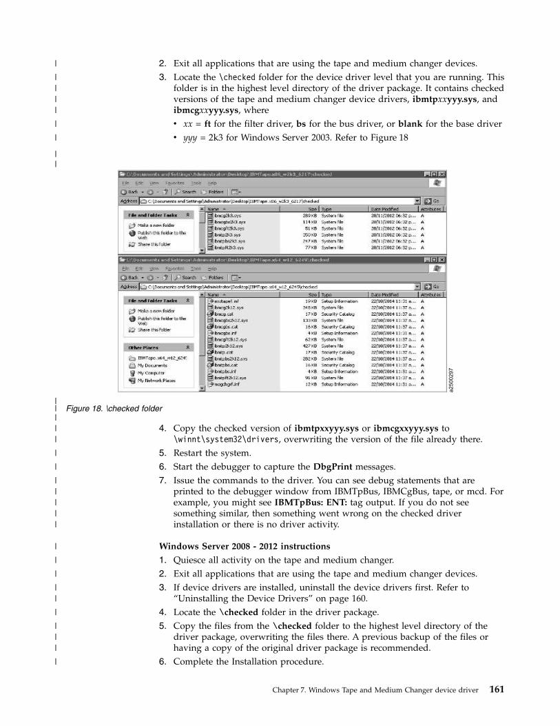
2. Exit all applications that are using the tape and medium changer devices.3. Locate the \checked folder for the device driver level that you are running. This
folder is in the highest level directory of the driver package. It contains checkedversions of the tape and medium changer device drivers, ibmtpxxyyy.sys, andibmcgxxyyy.sys, wherev xx = ft for the filter driver, bs for the bus driver, or blank for the base driverv yyy = 2k3 for Windows Server 2003. Refer to Figure 18
4. Copy the checked version of ibmtpxxyyy.sys or ibmcgxxyyy.sys to\winnt\system32\drivers, overwriting the version of the file already there.
5. Restart the system.6. Start the debugger to capture the DbgPrint messages.7. Issue the commands to the driver. You can see debug statements that are
printed to the debugger window from IBMTpBus, IBMCgBus, tape, or mcd. Forexample, you might see IBMTpBus: ENT: tag output. If you do not seesomething similar, then something went wrong on the checked driverinstallation or there is no driver activity.
Windows Server 2008 - 2012 instructions
1. Quiesce all activity on the tape and medium changer.2. Exit all applications that are using the tape and medium changer devices.3. If device drivers are installed, uninstall the device drivers first. Refer to
“Uninstalling the Device Drivers” on page 160.4. Locate the \checked folder in the driver package.5. Copy the files from the \checked folder to the highest level directory of the
driver package, overwriting the files there. A previous backup of the files orhaving a copy of the original driver package is recommended.
6. Complete the Installation procedure.
a2500297
Figure 18. \checked folder
Chapter 7. Windows Tape and Medium Changer device driver 161
|
|||
|
||||
|
|
|
||
|
|
|||||
|
|
|
||
|
|||
|

Restoring the non-Debug version
To restore the non-debug version of the driver, complete the following steps.
Windows Server 2003 instructions
1. Quiesce all activity on the tape and medium changer.2. Exit all applications that are using the tape and medium changer devices.3. In the highest level directory of the driver package, are non-debug versions of
the tape and medium changer device drivers, ibmtpxxyyy.sys andibmcgxxyyy.sys, wherev xx = ft for the filter driver, bs for the bus driver, or blank for the base driverv yyy = 2k3 for Windows Server 2003. Refer to Figure 19
4. Copy the non-debug version of ibmtpxxyyy.sys or ibmcgxxyyy.sys to\winnt\system32\drivers, overwriting the version of the file already there.
5. Restart the system. When the driver starts and commands are issued to it, thedriver no longer produces debug output.
Windows Server 2008 - 2012 instructions
1. Quiesce all activity on the tape and medium changer.2. Exit all applications that are using the tape and medium changer devices.3. Uninstall the device drivers first. Refer to “Uninstalling the Device Drivers” on
page 160.4. Restart the system.5. If a backup of device drivers package was done, complete the installation by
using backup. Otherwise, download the same device driver level again and
a2500298
Figure 19. \checked folder
162 IBM Tape Device Drivers: Installation and User's Guide
|
|||
|
|
|
|
|
|||
|
||
||
||
|
|
|
||
|
||

complete the installation. When the driver starts and commands are issued toit, the driver no longer produces debug output.
Chapter 7. Windows Tape and Medium Changer device driver 163
||
|

164 IBM Tape Device Drivers: Installation and User's Guide

Chapter 8. 3494 Enterprise Tape Library support
Purpose
The IBM 3494 Library device driver is a device driver providing attachment for theIBM 3494 Enterprise Automated Tape Library and IBM Virtual Tape Server (VTS)to a server. The programs that are described in this chapter support the 3494Enterprise Automated Tape Library on the following operating systems:v AIX on IBM POWER-based serversv HP-UXv Linuxv Solarisv Microsoft Windows
Note: Check the versions of operating system that is supported by the IBM tapedriver on each platform.
MTLIB program
The mtlib program is a command-line interface used to control the 3494 Enterprisetape library and is installed, by default, for execution by all users on the system.This program provides the full interface (except for the MTIOCLEW library systemcall) as specified in the IBM Tape Device Drivers: Programming Reference, GA32-0566.Refer to “MTEVENT program” on page 175.
The mtlib program provides an interface to the physical tape drives and volumeswithin a 3494 tape library and also to the virtual tape drives and volumes withinan attached IBM Virtual Tape Server (VTS).
To issue commands to the physical tape drives and volumes, specify a devicespecial file name, such as /dev/lmcp0 or the logical name of the library, such aslibmgrc7.
To issue commands to the virtual tape drives and volumes in an attached VTSlibrary, specify a device special file name or the logical name of the library withthe name of the logical VTS library that is appended with a slashv(/). For example,to issue commands to the first attached VTS library, use /dev/lmcp0/vts1 orlibmgrc7/vts1. The attached VTS libraries are named logically vts1, vts2, and so on.They correspond to the order in which they were configured in the tape library.The -D flag, with the -E flags, can be used to display the attached VTS devices andthe number of the VTS library.
Syntax and examples
Figure 20 on page 166 shows the syntax for the mtlib program.
© Copyright IBM Corp. 2007, 2015 165

The mtlib program has the following flags:
-f[filename]Device special file for the drive, for example, /dev/rmt0 (AIX),/dev/rmt/0st (Solaris), /dev/rmt/0m (HP), /dev/IBMtape0 (Linux),\\.\tape0 (Windows).
-x[number]Device number of the drive, for example, 518350.
-l[filename]On AIX, library special file name, for example, /dev/lmcp0,/dev/lmcp0/vts1. For non-AIX, the logical name of the library, for example,libmgrc7.
-q[type]Query the library information option:
V Volume data.
L Library data.
S Statistical data.
I Inventory data.
C Category inventory data.
D Device data.
E Expanded volume data.
K Inventory volume count data.
R Reserved category list.
Figure 20. Syntax diagram for mtlib program
166 IBM Tape Device Drivers: Installation and User's Guide

A Category attribute list.
M All mounted volumes.
-D Return an array of devices that are configured in the specified library.
-E Return (if used with the -D option) an array of expanded information forall devices that are configured in the specified library, including the controlunit ID, device, and VTS library number.
-m Mount option.
-d Demount option.
-c[requestid]Cancel the pending request option.
-n No wait mode.
-i[requestid]Query the request ID status option.
-C Change the category of a volume.
-a Audit the specified volume.
-k[flags]Assign a category (with one of the following flags) to a device in thelibrary:
O Enable the category order.
C Clear the cartridge loader.
G Generate the first mount.
A Enable the auto mount.
X Remove the device category assignment.
Note: Valid combinations are OG, OA, GA, and OGA.
-r Reserve the category.
-R Release the category.
-S Set the category attribute.
Note: The categories must be reserved before this option is used.
-s[category]Source or starting category.
-t[category]Target category.
-V[volser]Volume serial number.
-L[list]Filename containing a list of the volume serial numbers. Each VolumeSerial must be entered as one per line in the file.
-N[name]Category name to assign to the category (valid characters are uppercaseA-Z, 0-9, -, *, or blank).
Chapter 8. 3494 Enterprise Tape Library support 167

-h[hostid]Host ID for the reserve or release category or the R/A option for the querycommand.
-u Include usage date in the expanded volume data (used with the-qEoption). The default is the ISO format with a period separator. The formatcan be specified with the -F option.
-F[flags]Format or separator for volume usage and date with the -u option:
I ISO/Japan yyyy.mm.dd.
E Europe dd.mm.yyyy.
U US mm.dd.yyyy.
p Period separator mm.dd.yyyy.
d Dash separator mm-dd-yyyy.
s Slash separator mm/dd/yyyy.
-v Verbose.
-#[num_categories]Number of categories to reserve.
-A Query library addresses and status.
-? Help text.
Note: Thev-l argument is required.
The report in Table 30 was produced bymtlib -l /dev/lmcp0 -f /dev/rmt5 -qD (for AIX physical library)mtlib -l /dev/lmcp0/vts1 -f /dev/rmt5 -qD (for AIX VTS library 1)mtlib -1 libmgrc7 -f /dev/rmt/5st -qD (for Solaris)mtlib -1 libmgrc7 -f /dev/rmt/5m -qD (for HP)mtlib -1 libmgrc7 -f /dev/IBMtape5 -qD (for Linux)mtlib -l libmgrc7 -f \\.\tape0 -qD (for Windows)
Table 30. Device query
Device Data:mounted volser............TAF500mounted category..........FF00device category...........0000device state..............Device installed in Library.
Device available to Library.Volume is loaded.ACL is installed.
device class..............3590-B1Aextended device status....00
The report in Table 31 on page 169 was produced bymtlib -l /dev/lmcp0 -qV -VCS2000 (for AIX physical library)mtlib -l /dev/lmcp0/vts1 -qV -VCS2000 (for AIX VTS library 1)mtlib -l libmgrc7 -qV -VCS2000 (for Solaris, HP, Linux, SGI, Tru64, and Windows)
168 IBM Tape Device Drivers: Installation and User's Guide
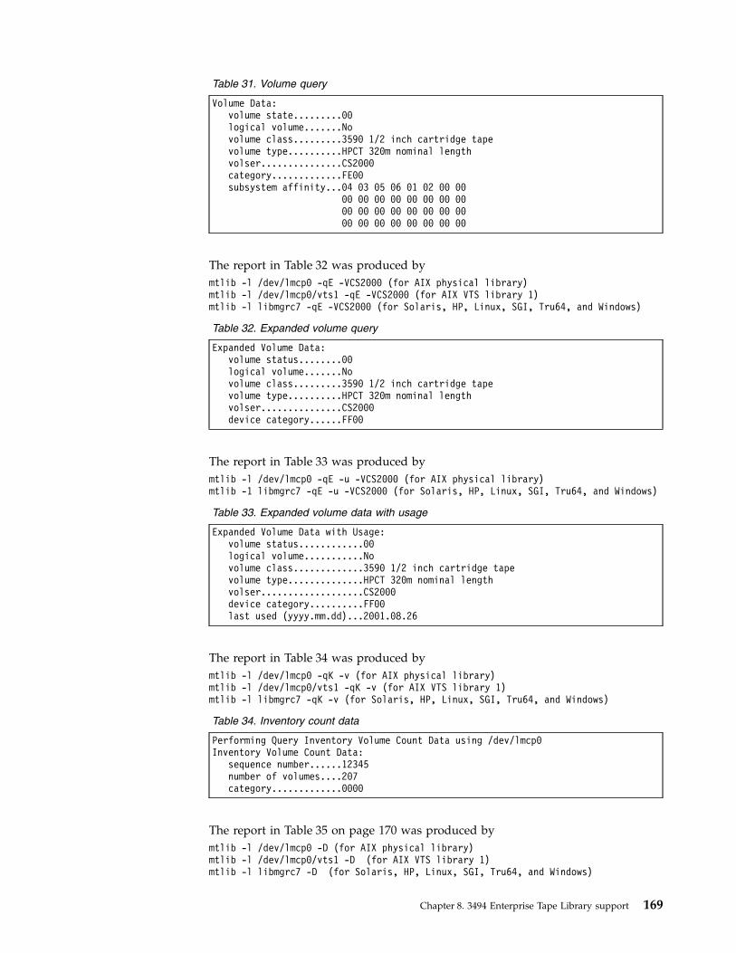
Table 31. Volume query
Volume Data:volume state.........00logical volume.......Novolume class.........3590 1/2 inch cartridge tapevolume type..........HPCT 320m nominal lengthvolser...............CS2000category.............FE00subsystem affinity...04 03 05 06 01 02 00 00
00 00 00 00 00 00 00 0000 00 00 00 00 00 00 0000 00 00 00 00 00 00 00
The report in Table 32 was produced bymtlib -l /dev/lmcp0 -qE -VCS2000 (for AIX physical library)mtlib -l /dev/lmcp0/vts1 -qE -VCS2000 (for AIX VTS library 1)mtlib -l libmgrc7 -qE -VCS2000 (for Solaris, HP, Linux, SGI, Tru64, and Windows)
Table 32. Expanded volume query
Expanded Volume Data:volume status........00logical volume.......Novolume class.........3590 1/2 inch cartridge tapevolume type..........HPCT 320m nominal lengthvolser...............CS2000device category......FF00
The report in Table 33 was produced bymtlib -l /dev/lmcp0 -qE -u -VCS2000 (for AIX physical library)mtlib -1 libmgrc7 -qE -u -VCS2000 (for Solaris, HP, Linux, SGI, Tru64, and Windows)
Table 33. Expanded volume data with usage
Expanded Volume Data with Usage:volume status............00logical volume...........Novolume class.............3590 1/2 inch cartridge tapevolume type..............HPCT 320m nominal lengthvolser...................CS2000device category..........FF00last used (yyyy.mm.dd)...2001.08.26
The report in Table 34 was produced bymtlib -l /dev/lmcp0 -qK -v (for AIX physical library)mtlib -l /dev/lmcp0/vts1 -qK -v (for AIX VTS library 1)mtlib -l libmgrc7 -qK -v (for Solaris, HP, Linux, SGI, Tru64, and Windows)
Table 34. Inventory count data
Performing Query Inventory Volume Count Data using /dev/lmcp0Inventory Volume Count Data:
sequence number......12345number of volumes....207category.............0000
The report in Table 35 on page 170 was produced bymtlib -l /dev/lmcp0 -D (for AIX physical library)mtlib -l /dev/lmcp0/vts1 -D (for AIX VTS library 1)mtlib -l libmgrc7 -D (for Solaris, HP, Linux, SGI, Tru64, and Windows)
Chapter 8. 3494 Enterprise Tape Library support 169
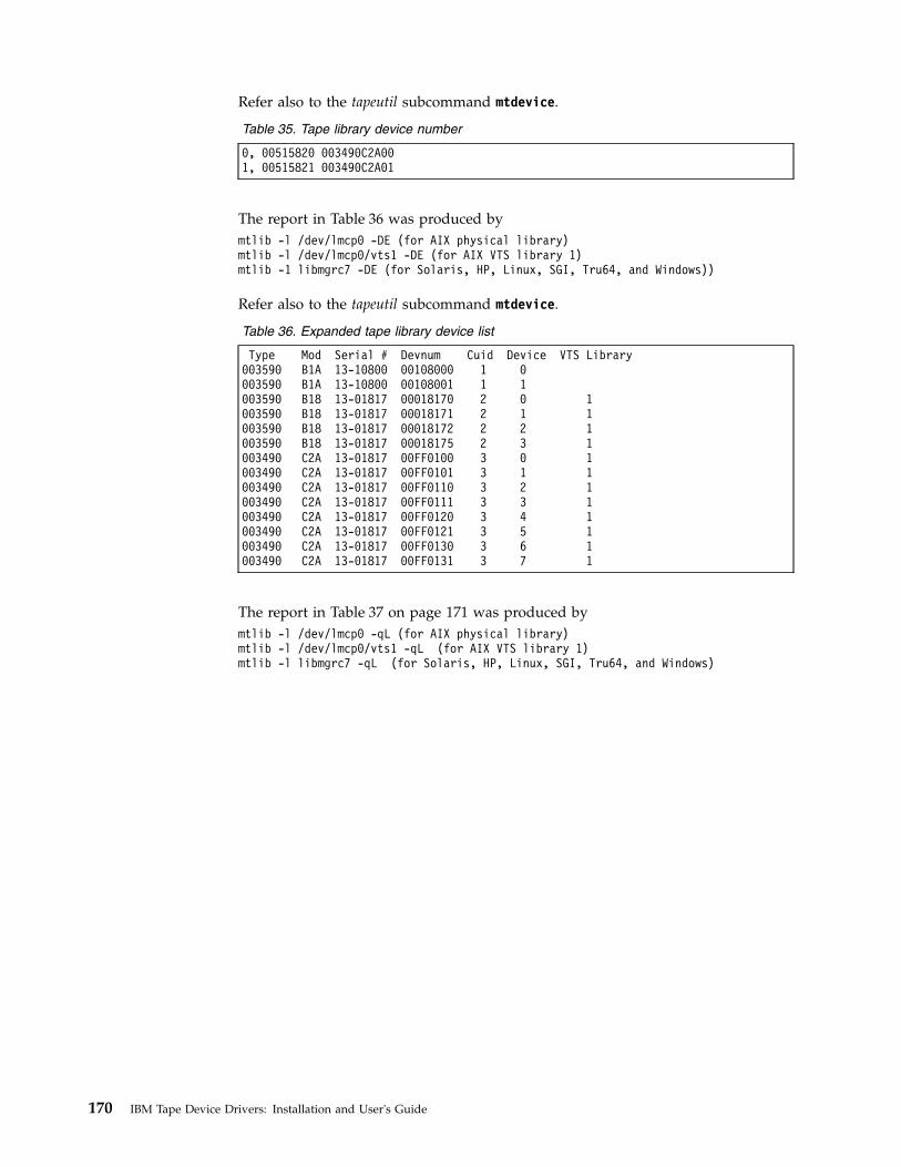
Refer also to the tapeutil subcommand mtdevice.
Table 35. Tape library device number
0, 00515820 003490C2A001, 00515821 003490C2A01
The report in Table 36 was produced bymtlib -l /dev/lmcp0 -DE (for AIX physical library)mtlib -l /dev/lmcp0/vts1 -DE (for AIX VTS library 1)mtlib -1 libmgrc7 -DE (for Solaris, HP, Linux, SGI, Tru64, and Windows))
Refer also to the tapeutil subcommand mtdevice.
Table 36. Expanded tape library device list
Type Mod Serial # Devnum Cuid Device VTS Library003590 B1A 13-10800 00108000 1 0003590 B1A 13-10800 00108001 1 1003590 B18 13-01817 00018170 2 0 1003590 B18 13-01817 00018171 2 1 1003590 B18 13-01817 00018172 2 2 1003590 B18 13-01817 00018175 2 3 1003490 C2A 13-01817 00FF0100 3 0 1003490 C2A 13-01817 00FF0101 3 1 1003490 C2A 13-01817 00FF0110 3 2 1003490 C2A 13-01817 00FF0111 3 3 1003490 C2A 13-01817 00FF0120 3 4 1003490 C2A 13-01817 00FF0121 3 5 1003490 C2A 13-01817 00FF0130 3 6 1003490 C2A 13-01817 00FF0131 3 7 1
The report in Table 37 on page 171 was produced bymtlib -l /dev/lmcp0 -qL (for AIX physical library)mtlib -l /dev/lmcp0/vts1 -qL (for AIX VTS library 1)mtlib -l libmgrc7 -qL (for Solaris, HP, Linux, SGI, Tru64, and Windows)
170 IBM Tape Device Drivers: Installation and User's Guide

Table 37. Library data
Library Data:Operational state..........Paused Operational State
Intervention Requiredfunctional state...........00input stations.............1output stations............1input/output status........All input stations empty
All output stations emptymachine type...............3494sequence number............10491number of cells............1056available cells............1014subsystems.................6convenience capacity.......30accessor config............01accessor status............Accessor available
Gripper 1 availableGripper 2 installedVision system operational
comp avail status..........Primary library manager installed.Primary library manager available.Secondary library manager installed.Secondary library manager available.Primary hard drive installed.Primary hard drive available.Secondary hard drive installed.Secondary hard drive available.Convenience input station installed.Convenience input station available.Convenience output station installed.Convenience output station available.
library facilities.........00bulk input capacity........0bulk input empty cells.....0bulk output capacity.......0bulk output empty cells....0avail 3490 cleaner cycles..0avail 3590 cleaner cycles..91
The report in Table 38 on page 172was produced bymtlib -l /dev/lmcp0 -qS (for AIX physical library)mtlib -l /dev/lmcp0/vts1 -qS (for AIX VTS library 1)mtlib -l libmgrc7 -qS (for Solaris, HP, Linux, SGI, Tru64, and Windows)
Chapter 8. 3494 Enterprise Tape Library support 171

Table 38. Statistical data
Statistical Data:hour index...........10machine type.........003494model number.........L10manufacturer.........IBMplant................13sequence number......000000010491drives...............6mounted drives.......1max mounted drives...2min mounted drives...1avg mounted drives...1max mounted time.....22min mounted time.....16avg mounted time.....19pending mounts.......0max pending mounts...2min pending mounts...0avg pending mounts...0mounts/hour..........18index mounts/hour....0pre-mounts/hour......0max mount time.......27min mount time.......16avg mount time.......19pending demounts.....0max pending demounts.2min pending demounts.0avg pending demounts.0demounts/hour........16index demounts/hour..0post-demounts/hour...0max demount time.....28min demount time.....19avg demount time.....24pending ejects.......0max pending ejects...0min pending ejects...0avg pending ejects...0ejects/hour..........0max eject time.......0min eject time.......0avg eject time.......0pending audits.......0max pending audits...0min pending audits...0avg pending audits...0audits/hour..........0max audit time.......0min audit time.......0avg audit time.......0input stores/hour....0
The report in Table 39 on page 173 was produced bymtlib -l /dev/lmcp0 -qI-v (for AIX physical library)mtlib -l /dev/lmcp0/vts1 -qI -v (for AIX VTS library 1)mtlib -l libmgrc7 -qI -v (for Solaris, HP, Linux, SGI, Tru64, and Windows)
172 IBM Tape Device Drivers: Installation and User's Guide

Table 39. Inventory query
Performing Query Inventory Data using /dev/lmcp0Inventory Data:
sequence number......10491number of volumes....44inventory records
record 1......category............012Cvolser..............008273volume state........00logical volume......Novolume class........3590 1/2 inch cartridge tapevolume type.........HPCT 320m nominal length
record 2......category value......FF00volser..............064435volume state........00logical volume......Novolume class........3590 1/2 inch cartridge tapevolume type.........HPCT 320m nominal length
record 3......category value......FF00volser..............ALTML1volume state........00logical volume......Novolume class........3590 1/2 inch cartridge tapevolume type.........HPCT 320m nominal length•••
record 42......category............FF00volser..............TST039volume state........00logical volume......Novolume class........3590 1/2 inch cartridge tapevolume type.........HPCT 320m nominal length
record 43......category............FF00volser..............TST182volume state........Volume present in Library,
but Inaccessiblerecord 44......category value......FF00
volser..............XYZ464volume state........00logical volume......Novolume class........3590 1/2 inch cartridge tapevolume type.........HPCT 320m nominal length
Note: All available records are produced as output per request.Fewer records are shown here for the sake of brevity.
The report in Table 40 on page 174 was produced bymtlib -l /dev/lmcp0 -qC -sFF00 -v (for AIX physical library)mtlib -l /dev/lmcp0/vts1 -qC -sFF00 -v (for AIX VTS library 1)mtlib -l libmgrc7 -qC -sFF00 -v (for Solaris, HP, Linux, SGI, Tru64, and Windows)
Chapter 8. 3494 Enterprise Tape Library support 173

Table 40. Category inventory query
Performing Query Category Inventory Data using /dev/lmcp0Inventory by Category Data:
sequence number......10491number of volumes....30category.............FF00inventory records
record 1......category ...........FF00volser..............CS2017volume state........00logical volume......Novolume class........3590 1/2 inch cartridge tapevolume type.........HPCT 320m nominal length
record 2......category ...........FF00volser..............FVT896volume state........00logical volume......Novolume class........3590 1/2 inch cartridge tapevolume type.........HPCT 320m nominal length
record 3......category ...........FF00volser..............IHG319volume state........00logical volume......Novolume class........3590 1/2 inch cartridge tapevolume type.........HPCT 320m nominal length•••
record 28......category ...........FF00volser..............SLT500volume state........00logical volume......Novolume class........3590 1/2 inch cartridge tapevolume type.........HPCT 320m nominal length
record 29......category ...........FF00volser..............TAF195volume state........00logical volume......Novolume class........3590 1/2 inch cartridge tapevolume type.........HPCT 320m nominal length
record 30......category ...........FF00volser..............MOO801volume state........00logical volume......Novolume class........3590 1/2 inch cartridge tapevolume type.........HPCT 320m nominal length
Note: All available records are produced as output per request.Fewer records are shown here for the sake of brevity.
The report in Table 41 was produced bymtlib -l /dev/lmcp0 -r -#2 -h roadster (for AIX physical library)mtlib -l /dev/lmcp0/vts1 -r -#2 -h roadster (for AIX VTS library 1)mtlib -l libmgrc7 -r -#2 -h roadster (for Solaris, HP, Linux, SGI, Tru64, and Windows)
Table 41. Reserve category command
Reserved Category List:sequence number............10491system token...............roadstertotal number reserved......0002
category......0101category......0102
174 IBM Tape Device Drivers: Installation and User's Guide

The report in Table 42 was produced bymmtlib -l /dev/lmcp0 -qR -h roadster (for AIX physical library)mtlib -l /dev/lmcp0/vts1 -qR -h roadster (for AIX VTS library 1)mtlib -l libmgrc7 -qR -h roadster (for Solaris, HP, Linux, SGI, Tru64, and Windows)
Table 42. Reserve category list
Reserved Category List:sequence number............10491system token...............roadstertotal number reserved......0002
category......0101category......0102
The report in Table 43 was produced bymtlib -l /dev/lmcp0 -S -S101 -NSCRATCH (for AIX physical library)mtlib -l /dev/lmcp0 -S -S102 -NWORKING (for AIX physical library)mtlib -l /dev/lmcp0 -qA -h roadster (for AIX physical library)mtlib -l /dev/lmcp0/vts1 -S -S101 -NSCRATCH (for AIX VTS library 1)mtlib -l /dev/lmcp0/vts1 -S -S102 -NWORKING (for AIX VTS library 1)mtlib -l /dev/lmcp0/vts1 -qA -h roadster (for AIX VTS library 1)mtlib -l libmgrc7 -S -S101 -NSCRATCH (for Solaris, HP, Linux, SGI, Tru64, and Windows)mtlib -l libmgrc7 -S -S102 -NWORKING (for Solaris, HP, Linux, SGI, Tru64, and Windows)mtlib -l libmgrc7 -qA -h roadster (for Solaris, HP, Linux, SGI, Tru64, and Windows)
Table 43. Category attribute list
Category Attribute List:sequence number............10491
system token...............roadstercategory 0101 –– name: SCRATCHcategory 0102 –– name: WORKING
The report in Table 44 was produced bymtlib -l /dev/lmcp0 -A (for AIX physical library)mtlib -l tire -A (for Solaris, HP, Linux, SGI, Tru64, and Windows)
Table 44. Library address information
Library Address Information:library name...............tirehost identification........roadsterprimary address............9.115.45.52primary status.............Onlinealternate address..........9.115.45.51alternate status...........Offline
MTEVENT program
The mtevent program is a command-line interface to the MTIOCLEW command.
The mtevent program has the following flags:
-l[filename]Library special file name or logical name of the library, for example,/dev/lmcp0, /dev/lmcp0/vts1, or libmgrc7.
-t[timeout]Number of seconds to wait for the event to occur.
Chapter 8. 3494 Enterprise Tape Library support 175

(0=no timeout).
Note:
1. The -l flag is required.2. If the -t flag is not supplied, then no timeout is completed.
Library driver information
The lmcpd communicates to the tape library through symbolic names that aredefined in the /etc/ibmatl.conf file. One or more symbolic names can be configuredfor each tape library online to the system. A symbolic name is used to run thevarious library functions (such as mounting and unmounting volumes).
Software interface
The Cvobject module provides three subroutines for communicating with the IBM3494 Enterprise tape library. These subroutines are open_ibmatl, close_ibmatl, andioctl_ibmatl. The open_ibmatl and close_ibmatl routines are used to open andclose communication with the library. Similarly, the open and close system callsare used to open and close communication with a file. The ioctl_ibmatl subroutineis used to send commands to the Library Manager on the 3494 tape library.
To send commands to the 3494 tape library, one symbolic name must be definedfor use on the library.
Library Manager event notification
In addition to completing library operations, the lmcpd is responsible for receivingthe various Library Manager notifications. The daemon monitors several types ofevents. When the daemon receives an event, it checks a list of processes that arewaiting for an event to determine where to deliver it. If no process is waiting forthe event that arrived, then the event is discarded. The applications can use theLibrary Event Wait call to request notification of all Library Manager events. Referto the IBM Tape Device Drivers: Programming Reference for information.
Synchronous and asynchronous operations
Two types of library operations are supported: synchronous and asynchronous.The Library Manager responds to the synchronous operation immediately. Theseoperations are completed when the library responds to the request. An example ofa synchronous operation is the Library Query call. An asynchronous operation(such as a mount operation) takes longer to complete. In an asynchronousoperation, the library returns an initial response when the command is acceptedfor execution. When the command is completed, it returns a delayed responsemessage that indicates the status of the operation.
Operation Complete notification
When the Mount, Demount, Audit, or Set Volume category operation is sent tothe library, a message identifier is assigned to the operation. This identifier isreturned to lmcpd. When the operation is completed, an operation completenotification is sent to the daemon. The daemon makes a determination (based onthe initial message identifier) as to which user process to notify that the operation
176 IBM Tape Device Drivers: Installation and User's Guide

is complete. The Mount, Demount, Audit, or Set Volume category operations havean option that allows the user process to wait or not wait for the operationcomplete message. If the user process does not wait for the final complete, theinitial message identifier is returned to the caller. It can be used in subsequentLibrary Query Message ID operations to solicit the status of the asynchronousoperation.
Unsolicited notification
There are situations when the Library Manager has a condition to report that is notrelated to any I/O operation. In this case, an unsolicited notification is sent to thedevice daemon. If a notification is received, then any process that is waiting withthe Library Event Wait call is notified. An example of an unsolicited notification isthe operational state change of the library (from the Auto mode to the Pausemode). Refer to the IBM Tape Device Drivers: Programming Reference for a list ofunsolicited notifications that are received by the lmcpd.
Driver message queue
The driver maintains a message queue for any process that has an open LMCP filedescriptor. This queue, which has a depth of four entries, is implemented on afirst-in, first-out basis. The purpose of this message is to reduce the possibility ofmissing a message when several messages occur in a short time. All queue entriesare discarded when the LMCP file descriptor is closed. When an application issuesthe MTIOCLEW input/output control (ioctl) call, the driver returns the oldestentry from the message queue and deletes it. If no entries are in the queue, thenthe calling process is put to sleep until a message is received.
Volume categories
To facilitate the management of the tape volumes within the 3494 tape library, thecapability to associate the tape volumes into logical groupings is provided. Eachlogical grouping is known as a category. For example, an installation can have oneor more scratch categories that are assigned by media type or class of user.Another potential use is managing volumes for daily, weekly, and monthlybackups or volumes that are owned by a specific user. The lmcpd also allows auser process to assign a particular category to a tape device in the library. Thisprocess allows all the volumes that are associated with the category to be mountedas determined by the flags of the command on the specified device.
A category is a four digit hexadecimal number in the X'0000'-X'FFFF' range. Theassigned categories are
X'0000'NULL category (not usable or not assigned).
X'0001'-X'FEFF'General programming use.
X'FFFF'VOLSER specific.
The X'FF00'-X'FFFE' categories are reserved for hardware functions.
X'FF00'Insert.
Chapter 8. 3494 Enterprise Tape Library support 177

X'FF01'-X'FF0F'Reserved.
X'FF10'Eject.
X'FF11'Bulk eject.
X'FF12'-X'FFF8'Reserved.
X'FFF9'Service volume.
X'FFFA'Manually ejected.
X'FFFB'Purge volume.
X'FFFE'Cleaner volume.
The following three categories are available for programming use.
Insert When a tape volume is received in the input station, the volume label isread and assigned to this category. This category cannot be assigned by auser process.
Eject The volumes that are assigned to this category are moved from their cellinto the output station. After the volume is delivered, it is removed fromthe inventory. The Library Set Volume Category command is the onlycommand that can change the category of a volume to the eject category.
Bulk ejectThe volumes that are assigned to this category are moved from theircurrent cell to the bulk output area in the 3494 tape library. Refer to theIBM Enterprise Automated Tape Library Operator Guide for information aboutthe bulk output area. The Library Set Volume Category command is theonly command that can change the category of a volume to the bulk ejectcategory.
The X'FFFF' category is available for general programming use. However, anymount request to this category must apply to a specific volume that is assigned tothe category (and not based on the category alone).
IBM TotalStorage Virtual Tape Server subsystem attachment
The device driver supports the IBM TotalStorage Virtual Tape Server (VTS)subsystem attachment with a 3494 Enterprise tape library on AIX, HP-UX,Windows, and Oracle Solaris systems. An attached VTS subsystem provides virtualtape drives that are accessible with the VTS SCSI attachment feature. Volumeswithin the VTS subsystem are logical tape volumes. A logical tape volume appearsto the host as a normal physical tape volume. However, the VTS logical volumesare unique to the VTS subsystem and are accessible only by virtual tape driveswithin the VTS subsystem.
Access to a VTS subsystem is specified to the device driver as a logical librarywithin the attached tape library as vts1, vts2, and so on. For example, issuing aQuery Inventory command to the 3494 lib returns the physical volumes in the 3494
178 IBM Tape Device Drivers: Installation and User's Guide

tape library, where 3494 lib is a library that is configured in the /etc/ibmat1.conffile. Issuing a Query Inventory command to 3494 lib/vts1 returns the logicalvolumes in the first VTS subsystem that is attached to the 3494 Enterprise tapelibrary.
3494 Library emulation
With 3494 Library emulation support, you can use applications that were writtenfor the 3494 API on host attached SCSI Medium Changer libraries. Specifically, youcan use migration to the 3584 Ultra Scalable library with 3592 drives.
Overview
Existing customer scripts that use the mtlib program and customer or ISVapplications require no or minor changes to use, depending on the 3494 functionsthat are used. Customer and ISV applications must be recompiled only with thenew libibm.o object module to use the emulation support. The mtlib 3494 usercommand line interface program has the same syntax and output on everyoperating system. It also provides a common utility for SCSI Medium Changerlibraries. Current operating system device driver utilities vary by syntax or output.They require a knowledge of SCSI Medium Changers to use, and require multiplecommands to run a single mtlib command.
3494 Emulation design
The 3494 Emulation support adds a libsmc extension to the current libibm.o objectmodule that applications compile with for existing 3494 support. The libsmcextension contains the 3494 API Emulation support. The extension issues SCSIMedium changer commands to the library by using the operating system SCSIMedium Changer device driver.
Figure 21 and Figure 22 on page 180 show the 3494/SMC data flow between existingapplications and components and the new libsmc extension.
3494/ SMC Library Data Flow
3494Library Manager
LibraryTape Drive
TCP/IPLMCPD
Tape DeviceDriver
AdapterDevice Driver
Application
LIBIBM.OObjectModule
LIBSMC SCSI MediumChanger
AdapterDevice Driver
SMC DeviceDriver
a28
t100
1
Figure 21. 3494/SMC library data flow
Chapter 8. 3494 Enterprise Tape Library support 179

3494 API Emulation and MTLIB program
Refer to the IBM Tape Device Drivers Installation and User's Guide and theIBM TapeDevice Drivers Programmer's Reference for the complete description of 3494 librarysupport and the mtlib program and syntax.
SMC library names
The library name on the open_ibmatl ("libname") or mtlib -l libname parameterdetermines whether a 3494 library or an SMC library is being used. If the libraryname is a logical operating system SMC library name, then the libsmc support isused. Otherwise, the lmcpd support is used.
For example, SMC libraries on AIX are named smc0, smc1, and so on. To issue anmtlib query library command on AIX to a 3584 library named smc0,mtlib -l smc0 -qL
To issue an mtlib command on Linux to a 3584 library named IBMchanger0,mtlib -l IBMchanger0 -qL
Volume categories
The 3494 library supports the grouping of one or more volumes into categoriesthat can be assigned by an application and operations that can specify a categoryonly rather than a specific volume. SCSI Medium Changers do not provide asimilar function. All volumes in an SMC library are category 0000, the NULLcategory.
LIBSMC and O/S Components
HPUXatdd Device
Driver
SolarisIBMtape Device
Driver
AIXAtape Device
Driverlibsmc.c
3494 APIEmulation
SCSI MediumChanger
Commands
libsmc_aix.c
libsmc_sun.c
libsmc_hp.c
libsmc_linux.c
libsmc_win.c
LinuxIBMtape Device
Driver
WindowsIBMtape Device
Driver a28
t1002
Figure 22. LIBSMC and OS components
180 IBM Tape Device Drivers: Installation and User's Guide
Because volume categories are not supported, the following API and mtlibcommand options cannot be used. Applications and mtlib scripts that use thesefunctions might require changes.v Reserve category mtlib -r optionv Release category mtlib -R optionv Change a volume category mtlib -C optionv Set category attribute mtlib -S optionv Assign a category mtlib -k optionv Mount from a category mtlib -m -s option
Asynchronous library operations
The 3494 library runs all mount, demount, audit, and eject operationsasynchronously and initially returns a request id to the host for the operation. Therequest id can then be queried at any time to determine whether the operation isstill pending, completed, or is unknown. SMC libraries run these operationssynchronously and do not support a request id.
An application can select to wait for an asynchronous operation to complete bysetting the API wait_flg to one or by using mtlib without the -n option. Theoperation is synchronous on both a 3494 and SMC library and no request id isreturned to the application. These applications and mtlib scripts do not requireany changes.
If an application selects to not wait for an asynchronous operation to complete bysetting the API wait_flg to zero or by using mtlib with the -n option, theoperation on an SMC library is still synchronous. A request id 0 is returned to theapplication.
Most applications and scripts do not use the return request id to determine whenthe operation completes and uses the no wait option for performance only. Forexample, by using the no wait option on a demount operation so the applicationcan continue while the library is demounting the volume. These applications andmtlib scripts do not require any changes but do take the same amount of time asthe wait option.
Applications that use the Query Message ID or mtlib -i option to determine whenthe return request id operation completes might require changes. One change ispolling for a mount that is issued with the no wait option since any request id isalways unknown on an SMC library because the operation is already complete.
Performance considerations
The performance time of mtlib commands that are issued to a SCSI 3584 libraryversus a 3494 vary and some performance times might be higher. The mtlibcommands, such as -qV and -qI that require reading all the slot information fromthe library also vary in the amount of time it takes for the command to complete.The fewer the number of slots that are in the library, the shorter time it takes tocomplete the mtlib command and a larger number of slots in the library takeslonger.
Chapter 8. 3494 Enterprise Tape Library support 181

AIX
The software consists of an Automated Tape Library Device Driver (atldd), anapplication daemon (lmcpd) that communicates with the 3494 Library Manager(LM), and a utility program (mtlib), which provides a command-line interface tothe library. Either an ethernet, token-ring LAN, or an RS-232 serial connection canbe used for the physical connection between the host and the 3494 LM.
The daemon, which is known to AIX specifically as the IBM Library ManagerControl Point Daemon (lmcpd), communicates with tape libraries that are definedin a configuration file. This file, ibmatl.conf, is placed in the /etc directory whenthe software package is installed. Customization of this file is described in“Defining tape libraries to the daemon” on page 184. A typical environment for theAIX 3494 Enterprise Library Driver is an RS/6000 or System p (also known aspSeries) server on a local area network (LAN) with SCSI- or fibre-attached tapedrives that provide backup and restore functions.
Data flow
The software described in this chapter covers the library device driver and theinterface between the application and the library device driver. For information,refer to Figure 23.
Figure 23. Data flow for AIX 3494 Enterprise Tape Library Driver
182 IBM Tape Device Drivers: Installation and User's Guide

Product requirements
The following hardware and software components are supported by IBM.
Hardware requirements
The library driver supports the following hardware.v One of the following options, depending on the connection (RS-232 or LAN)
required for the Library Manager,– RS-232
- One standard 25 pin null modem D-shell RS-232 cable- (maximum of 15.24 meters [50 feet])
– LAN- Token Ring or Ethernet Adapter support in an RS/6000 or pSeries
workstation that is attached to the Library Manager- LAN cabling (as required)
v IBM TS1120 Tape Drive Model EO5v IBM TS1130 Tape Drive Model E06v 3592 Tape Drive Model J1A
Software requirements
The following software is required for the library driver:v AIX 5L, Version 5.3, and later releases on IBM POWER-based servers.v AIX Tape and Medium Changer Device Driver (Atape)
To obtain the most current service and documentation for this software, refer toAppendix A, “Accessing documentation and software online,” on page 327
Installation instructions
Use the standard set of AIX methods to install and configure the LMCP devices.You must have root authority to complete these operations.
Installation procedure
Refer to Appendix A, “Accessing documentation and software online,” on page 327for information on obtaining the latest versions of the device driver and the latestdocumentation.
Enter the following command to list the currently installed version of the 3494Enterprise Library Driver:lslpp -l atldd.driver
Connecting the IBM Enterprise tape library
If a tty connection is needed, use a standard 25 pin null modem D-shell RS-232cable to connect the workstation to the 3494 Enterprise tape library. Place the cableon the native serial port or on the 8 port or 16 port asynchronous adapter.
If a LAN connection is needed, connect the LAN cable from the Token Ring orEthernet adapter card in the workstation to the 3494 tape library.
Chapter 8. 3494 Enterprise Tape Library support 183

Note: The cable (RS-232 or LAN) must be in place before the software is installedto ensure correct initialization of the driver.
Configuring the serial port
After the 3494 tape library is connected to the workstation, you must configure theserial port to which it is connected. Use smit to configure the serial port. Enter thefollowing command:smit tty
Select the following options.1. TTY menu: Add a tty device.2. Selection menu: Select the appropriate parent serial adapter.3. Add TTY menu: Enter the port number.
Press F4 to generate a list of possible values.4. Add TTY menu: Set baud rate to 9600.5. Add TTY menu: eight data bits, one stop bit, no parity.6. Add TTY menu: Set Enable program to Off.
Press F4 to generate a list of possible values.7. Add TTY menu: Set Enable LOGIN to disable.
Use Tab to toggle the value.8. Press Return to configure the tty device.
Repeat steps 1 - 8 for each tape library that is connected to the workstation.
Configuring the IBM 3490E or 3590 tape drive
To operate the 3494 Enterprise tape library successfully through the configuredLMCPs, you must configure all 3490E or 3590 tape drives in the 3494 tape library.Refer to “Configuring the Library Manager Control Point” on page 185 forinstructions.
Defining tape libraries to the daemon
After the software is installed and the tape libraries are connected to the system,the /etc/ibmatl.conf file must be edited to define the tape libraries to the lmcpd.The format of the file isSymbolic name Connection type Identifier Alternate LAN Connection
Symbolic name is used to identify each library. The symbolic names must be uniqueacross all libraries that are defined in the /etc/ibmatl.conf file.
Connection type is used to define the type of connection to the library (eitherRS-232 or TCP/IP). For RS-232 connections, this type is the device special file nameof the tty device (for example, /dev/tty0 or /dev/tty1). For TCP/IP connections, thistype is the IP address of the Library Manager. If the library has a dual LAN cardthat is installed, the second IP address of the dual LAN card must be entered afterthe first IP address.
Note: Ensure that duplicate IP addresses are not used in this file or unpredictableresults can occur.
Identifier is used to specify a name by which the Library Manager identifies thehost machine. This identifier has a maximum of 8 characters. The host name of the
184 IBM Tape Device Drivers: Installation and User's Guide

workstation is usually the best name to use (although it is not necessary). Thisparameter is used only to identify a particular host to the 3494 Enterprise LibraryManager.
Alternate LAN Connection is used to specify an alternate IP address for a 3494High Availability LAN attached configuration. If the High Availability Library hasa dual LAN card that is installed, the second IP address of the dual LAN cardmust be entered after the first alternate LAN connection IP address.
Note: For RS-232 attachments, the alternate LAN connection is not applicable.Failover for RS-232 connections proceeds over the single serial line.
The following examples show how to define the library name.libmgrc7 /dev/tty0 mercury
This stanza defines the libmgrc7 library that is connected by /dev/tty0 to theworkstation. The library uses the mercury identifier for the host.libmgrc8 9.115.32.21 jupiter
This stanza defines the libmgrc8 library that is connected through TCP/IP to theworkstation. The address of the Library Manager on the 3494 Tape Library is9.115.32.21. The library uses the jupiter identifier for the host.libmgrc9 9.115.46.15 telos 9.115.46.17
This stanza defines the libmgrc9 High Availability library that is connectedthrough TCP/IP to the workstation. The IP addresses of the dual Library Managersare 9.115.46.15 and 9.115.46.17.libmgrc7 9.115.32.21 9.115.32.22 mercury
This stanza defines libmgrc7 with a dual LAN card connected through TCP/IP tothe workstation. The first address of the Library Manager on the 3494 Tape Libraryis 9.115.32.21 and the second address is 9.115.32.22. The library uses the mercuryidentifier for the host.
The following stanza defines the libmgrc7 High Availability library with dual LANcards connected through TCP/IP to the workstation. The IP addresses of the firstLibrary Manager are 9.115.32.21 and 9.115.32.22. The IP addresses of the secondLibrary Manager are 9.115.26.13 and 9.115.26.14. The library uses the mercuryidentifier for the host.libmgrc7 9.115.32.21 9.115.32.22 mercury 9.115.26.13 9.115.26.14
Configuring the Library Manager Control Point
After the driver is installed, a tape library is connected to the workstation, and theserial port is configured, you can configure the instances of the LMCP. Completethe following procedure to define and configure the LMCP:1. Enter the following command:
smit
The system management interface tool (smit) main menu is displayed (refer toTable 45 on page 186).
Chapter 8. 3494 Enterprise Tape Library support 185
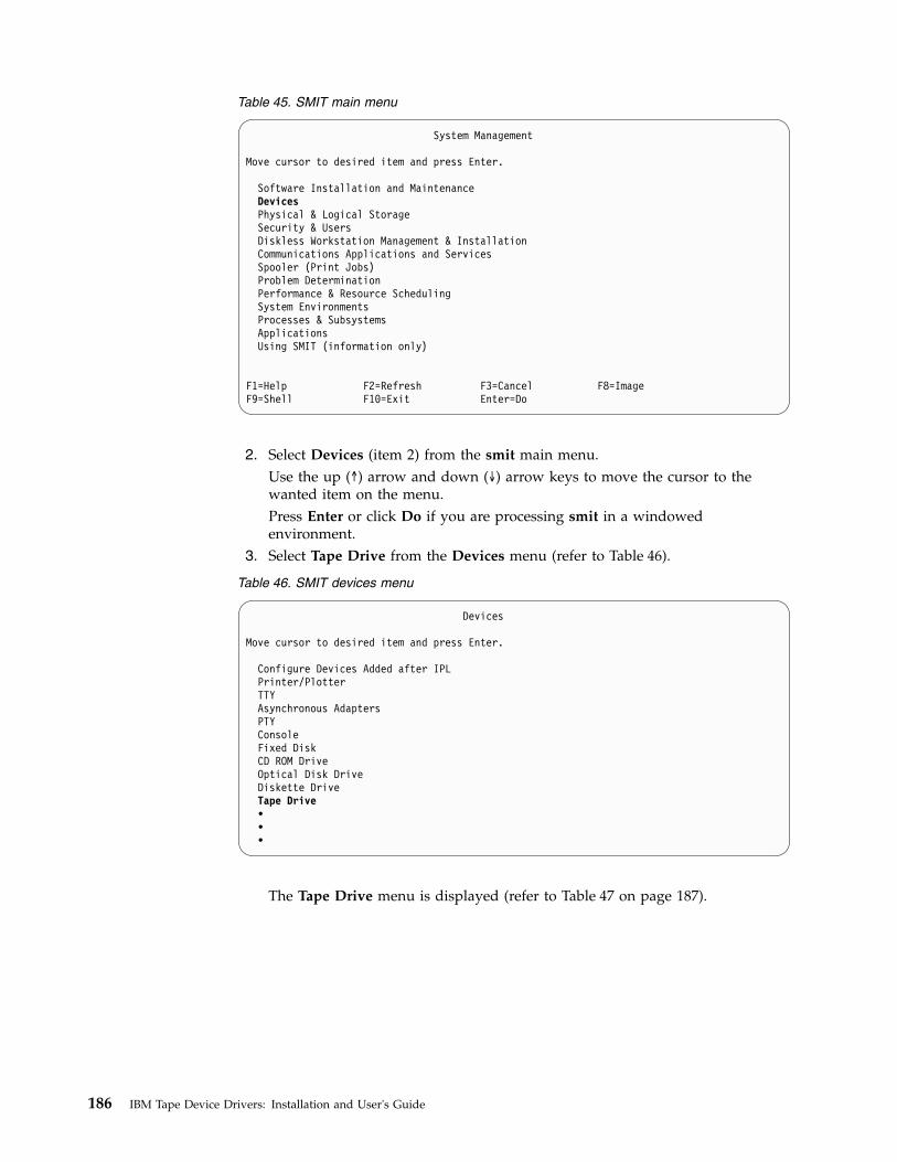
Table 45. SMIT main menu
System Management
Move cursor to desired item and press Enter.
Software Installation and MaintenanceDevicesPhysical & Logical StorageSecurity & UsersDiskless Workstation Management & InstallationCommunications Applications and ServicesSpooler (Print Jobs)Problem DeterminationPerformance & Resource SchedulingSystem EnvironmentsProcesses & SubsystemsApplicationsUsing SMIT (information only)
F1=Help F2=Refresh F3=Cancel F8=ImageF9=Shell F10=Exit Enter=Do
2. Select Devices (item 2) from the smit main menu.Use the up (↑) arrow and down (↓) arrow keys to move the cursor to thewanted item on the menu.Press Enter or click Do if you are processing smit in a windowedenvironment.
3. Select Tape Drive from the Devices menu (refer to Table 46).
Table 46. SMIT devices menu
Devices
Move cursor to desired item and press Enter.
Configure Devices Added after IPLPrinter/PlotterTTYAsynchronous AdaptersPTYConsoleFixed DiskCD ROM DriveOptical Disk DriveDiskette DriveTape Drive•••
The Tape Drive menu is displayed (refer to Table 47 on page 187).
186 IBM Tape Device Drivers: Installation and User's Guide

Table 47. SMIT tape drive menu
Tape Drive
Move cursor to desired item and press Enter.
List All Defined Tape DrivesList All Supported Tape DrivesAdd a Tape DriveChange / Show Characteristics of a Tape DriveRemove a Tape DriveConfigure a Defined Tape DriveGenerate Error ReportTrace a Tape Drive
4. Select Add a Tape Drive from the Tape Drive menu (Table 47). The TapeDrive Type menu is displayed (refer to Table 48).
5. Select the Library Manager control point from the Tape Drive Type menu(refer to Table 48).
Table 48. SMIT tape drive type menu
Tape Drive Type
Move cursor to desired item and press Enter.
8mm scsi 2.3 GB 8 mm Tape Drive9trk scsi 1/2 Inch 9 Track Tape Drive150mb scsi 150 MB 1/4 Inch Tape Driveost scsi Other SCSI Tape Drivedrive 3420 3420 Tape Drivedrive 3480 3480 Tape Drivedrive 3490 3490 Tape Driveatl library LAN/TTY Library Manager Control Point
The Add an LMCP Logical Device menu is displayed (refer to Table 49).The Logical Name field for the Library Manager control point is optional. Ifthe field remains blank, a unique name is assigned automatically. Theassigned name is lmcpn, where: n is a number that indicates the LMCP entryand starts with zero for the first LMCP defined.The Library Name field must be one of the library names that are defined inthe /etc/ibmatl.conf file. Refer to “Defining tape libraries to the daemon” onpage 184 for a description of this file.The Command Timeout in Minutes field is optional and is used to specifythe maximum amount of time an application waits for commands to complete,including mount and demount commands. The default is to wait forever untilthe command completes.
Table 49. Add an LMCP Logical Device menu
Add an LMCP Logical Device
Type or select values in entry fields.Press Enter AFTER making all desired changes.
[Entry Fields]Logical Name of LMCP (optional) []Library Name (F4 to list library names) [libmgrc7] +Command Timeout in Minutes []
Chapter 8. 3494 Enterprise Tape Library support 187
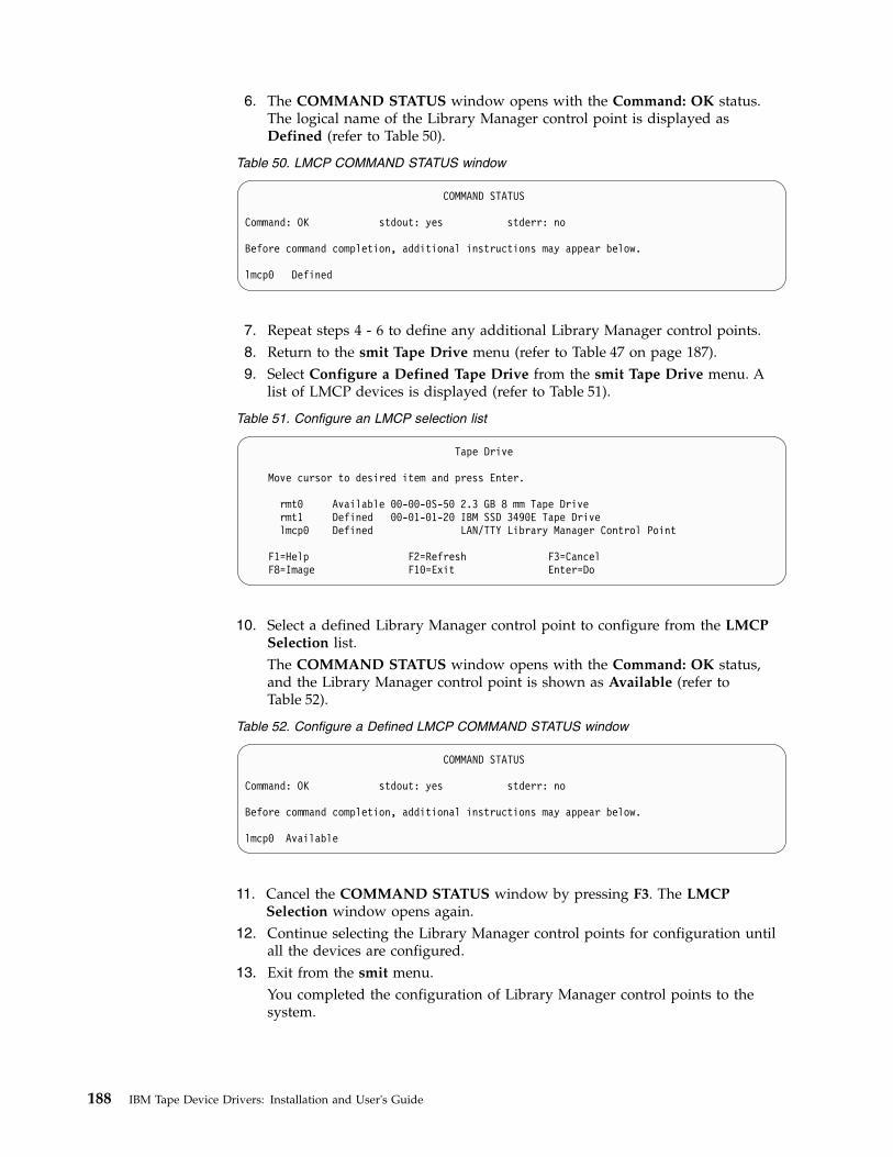
6. The COMMAND STATUS window opens with the Command: OK status.The logical name of the Library Manager control point is displayed asDefined (refer to Table 50).
Table 50. LMCP COMMAND STATUS window
COMMAND STATUS
Command: OK stdout: yes stderr: no
Before command completion, additional instructions may appear below.
lmcp0 Defined
7. Repeat steps 4 - 6 to define any additional Library Manager control points.8. Return to the smit Tape Drive menu (refer to Table 47 on page 187).9. Select Configure a Defined Tape Drive from the smit Tape Drive menu. A
list of LMCP devices is displayed (refer to Table 51).
Table 51. Configure an LMCP selection list
Tape Drive
Move cursor to desired item and press Enter.
rmt0 Available 00-00-0S-50 2.3 GB 8 mm Tape Drivermt1 Defined 00-01-01-20 IBM SSD 3490E Tape Drivelmcp0 Defined LAN/TTY Library Manager Control Point
F1=Help F2=Refresh F3=CancelF8=Image F10=Exit Enter=Do
10. Select a defined Library Manager control point to configure from the LMCPSelection list.The COMMAND STATUS window opens with the Command: OK status,and the Library Manager control point is shown as Available (refer toTable 52).
Table 52. Configure a Defined LMCP COMMAND STATUS window
COMMAND STATUS
Command: OK stdout: yes stderr: no
Before command completion, additional instructions may appear below.
lmcp0 Available
11. Cancel the COMMAND STATUS window by pressing F3. The LMCPSelection window opens again.
12. Continue selecting the Library Manager control points for configuration untilall the devices are configured.
13. Exit from the smit menu.You completed the configuration of Library Manager control points to thesystem.
188 IBM Tape Device Drivers: Installation and User's Guide

Loading the daemon
The lmcpd is loaded during the system initialization. During the initial installationof the driver, you must load the daemon manually by using the followingcommand,cfgmgr
You can access the 3494 Enterprise Tape Library after the command is completed.
To verify that the daemon is loaded correctly, enter the following command,ps -efa | grep lmcpd
You can see multiple instances of the daemon running (which is typical), but onlyone instance has a parent process ID of 1.
Deconfiguring the Library Manager Control Point
In the following examples, replace the letter n with the appropriate number for thechosen device.
Deconfigure the LMCP device by using one of the following procedures:1. The first method deconfigures the device but leaves the device that is defined
in the configuration database. It is similar to taking the device offline.Enter the following command to deconfigure the /dev/lmcpn device but leave itdefined in the device database.rmdev -l lmcpn
2. The second method takes the device offline and removes the device definitionfrom the device database.Enter the following command,rmdev -l lmcpn -d
The device driver modules are not unloaded from the kernel until the last tapedevice is deconfigured.
Uninstall procedure
All devices that use the atldd driver must be closed and not in use when atldd isuninstalled or the uninstall fails.
You can uninstall the atldd by using the smit command menu to uninstall softwareand selecting atldd.driver or use the following installp command,installp -u atldd.driver
Special files
After the driver is installed and a Library Manager control point is configured andmade available for use, access is provided through the special files. These specialfiles are in the /dev directory. Each instance of an LMCP has exactly one special file(for example, /dev/lmcp0) associated with it.
3494 Enterprise tape library attachment test
The following procedure tests the attachment of a 3494 Enterprise Tape Library toan AIX system. The procedure assumes that your device is defined as /dev/lmcp0.
Chapter 8. 3494 Enterprise Tape Library support 189

1. Open an AIX window.2. Enter mtlib -l /dev/lmcp0-qI3. Enter mtlib -l /dev/lmcp0 -qL
Problem determination
A set of tools is provided with the device driver to determine whether it isfunctioning correctly. The standard AIX interface is provided for problemdetermination.
Error logging
The driver provides logging to the system error log for various errors. View theerror log by using the smit or the errpt command. The error templates follow thesame form as the default AIX error log entries.
AIX device driver trace facility
The AIX trace facility is supported for the device driver. The trace event isidentified with a hookword. The hookword that is used by the device driver is 426.The trace can be initiated at any time before an operation on a tape device.
Enter the following command to start the trace.trace -a -j 426
This command starts the trace in the background and collects only the trace eventswith the 426 hookword.
Enter the following command to stop the trace.trcstop
This command stops the trace after the tape operations are completed.
Enter the following command to view the trace.trcrpt > lmcp.trace.out
This command formats the trace output into a readable form and places it in a filefor viewing. The /etc/lmcp.trcfmt file is installed into /etc during installation. Itprovides the formatting statements that are needed by trcrpt.
Daemon trace facility
The following trace facility is available for the lmcp daemon and device driver:trcatl -[ald]
Arguments:-a (trace all libraries defined in /etc/ibmatl.conf)-l <name> (name of library)-d (delete all log files; requires root authority)
Examples:trcatl -a >/tmp/trace-outtrcatl -l libmgrc7
Note: The -a argument takes precedence over the -l argument.
190 IBM Tape Device Drivers: Installation and User's Guide
HP-UX
The software consists of a daemon that communicates directly with the LibraryManager of the 3494 Enterprise tape library through Ethernet or Token Ring LAN,a utility program that provides a command line interface to the daemon, and a Cobject module that can be linked with user applications to provide acommunication interface with the daemon.
Note: In the HP-UX operating system, this daemon is a program that runsunattended in the background to run a standard service. Some daemons aretriggered automatically to complete their task, others operate periodically.
This software is known as a driver throughout this document because it providesthe software and interface necessary to drive the 3494 tape library. However, theproduct does not consist of a device driver in the true sense of the term. That is, it isnot an extension of the operating system kernel, such as a SCSI tape device driver.
A typical environment for the HP-UX Automated Tape Library Driver is an HPworkstation that acts as a data server on a network with SCSI tape devices thatprovides backup or restore and data server functions.
The Library Manager control point daemon (lmcpd) is provided in the package.The lmcpd is a process that is always running on the system. It provides directcommunication with the 3494 Enterprise Library Manager. An application linkswith the supplied C object module by using the interface that is described in theIBM Tape Device Drivers: Programming Reference. The subroutines in this modulecommunicate with the lmcpd to run the various library operations by usingstandard UNIX namespace sockets.
The lmcpd communicates with the Library Manager through TCP/IP. The/etc/ibmatl.conf configuration file is used to define the attachment for each library.Refer to “Defining the library device to LMCPD” on page 195 for information.
Data flow
The software described in this chapter covers the library driver. The interfacebetween the application and the library driver is described in the IBM Tape DeviceDrivers: Programming Reference. Figure 24 on page 192 illustrates the data flow.
Chapter 8. 3494 Enterprise Tape Library support 191

Product requirements
The following software and hardware are required to use this product.
Hardware requirements
The following hardware is required for the library driver.v 3494 Enterprise Tape Library with 3590 and 3592 drives.v IBM Virtualization Engine TS7510 and TS7520v Enterprise Model B10, B18, and B20 Virtual Tape Server (direct attached only)v One of the following options, depending on which LAN connection is used for
the Enterprise Library Manager– Token-Ring Attach -
- Enterprise FC 5219 (Token-Ring Adapter)- Token-Ring adapter card for HP workstation- Token-Ring cables (as required)
– Ethernet Attach -- Enterprise FC 5220 (Ethernet Adapter)- Ethernet port or adapter for HP workstation- Ethernet cables (as required)
Software requirements
The following software is required for the library driver.v HP-UX operating system
Application
Tape DeviceDriver
AdapterDevice Driver
LMCPD TCP/IP
PhysicalTape Drive
LibraryManager
CObjectModule
a2501
06
Figure 24. Data flow for HP-UX 3494 Enterprise tape library driver
192 IBM Tape Device Drivers: Installation and User's Guide

Note: For information, refer to Chapter 4, “HP-UX Tape and Medium Changerdevice driver,” on page 51.
v IBM Tape and Medium Changer Device Driver for HP-UX
To obtain the most current service and documentation for this software, refer toAppendix A, “Accessing documentation and software online,” on page 327.
Software compatibility
The following optional software is supported by the library driver:
IBM Tivoli Distributed Storage Manager for HP-UX
Installation instructions
This chapter describes how to install, configure, and uninstall the HP-UXAutomated Tape Library Support for the 3494 Enterprise tape library. The IBM tapelibrary driver for HP-UX is installed by using the standard swinstall process. TheIBM tape library driver for HP-UX is the lmcpd package.
Installation overview
LAN support must exist on the machine before the IBM tape library driver forHP-UX is installed. Install and configure the LAN support before you proceed withthe installation of the lmcpd package. For information, refer to the HP-UXdocumentation appropriate for the LAN support that you are using.1. Copy the software from the distribution medium to the depot.2. Check the readme file and verify that your system is configured appropriately
for installing the lmcpd software.3. Install and configure the software.
You must have root authority to run this installation procedure.
The distribution diskette contains a swinstall process that includes the lmcpddaemon with other associated files and utilities.
Command sequence information
Take note of the following facts about the command sequences described in thissection:v In some of the examples, file names that are given on the command line must be
referenced with an absolute path. Using 'pwd'/filename to reference a fileinstead of filename ensures the absolute path.
v All the SD commands (for example, swinstall, swcopy) can be run initially withthe '-p' flag to preview the command. After the preview output is observed,you can reissue the command without the '-p' flag to run the actual operation.
v The SD commands are moderately complex scripts that usually proceed inseveral steps. The steps are typically Selection, Analysis, and Execution. Eachstep might produce useful information and error messages. It is a good idea toobserve carefully the results of the installation process as it occurs.
If you run into unexpected results during the installation, check the associated logfile.
Chapter 8. 3494 Enterprise Tape Library support 193

Note: If an earlier version of the product is installed on the machine, run theuninstallation procedure before you enter the following commands. Refer to“Uninstallation procedure” on page 196 for information.
The following files are installed on the system:v /etc/lmcpd (Library Manager control point daemon)v /etc/ibmatl.conf (configuration file)v /usr/lib/libibm.o (32-bit application interface object module)v /usr/lib/libibm64.o (64-bit application interface object module)v /usr/lib/libibmz.0 (32-bit application interface object module with +z option)v /usr/lib/libibm64z.0 (64-bit application interface object module with +Z option)v /usr/lib/libibm_ia64.0 (64-bit application interface object module with +z option
for Itanium system)v /usr/lib/libibm_ia64z.0 (64-bit application interface object module with +Z
option for Itanium system)v /usr/include/sys/mtlibio.h (application interface header file)v /usr/bin/mtlib (tape library driver utility program)v /usr/bin/intlib64 (64-bit tape library driver utility program)v /usr/bin/mtevent (tape library driver utility program)v /usr/bin/trcatl (tape library driver diagnostic program)v /opt/lmcpd (subdirectory)v /opt/lmcpd/ibmatl.conf (backup configuration file)
Note: If you are updating the lmcpd package, the existing /etc/ibmatl.conf file ispreserved. It is not overwritten. A copy of ibmatl.conf is also installed in the/opt/lmcpd directory.
Installing the product manually
Installing the product manually requires two steps, detailed in the followingsections.1. “Copying the software to the Software Depot”2. “Installing the product”
Copying the software to the Software Depot
If you do not copy the lmcpd software into a depot, you cannot easily uninstall thesoftware.
Copy the appropriate driver to the Software Depot. For example,# swcopy -p -s /driver_location/lmcpd.hpux.x.x.x.x lmcpd (preview option)# swcopy -s /driver_location/lmcpd.hpux.x.x.x.x lmcpd
Use swlist to verify that the lmcpd software is in the depot.# swlist -d lmcpd
Installing the product
When the software is in the depot, the lmcpd software can be installed to the rootfile system by using the HP-UX swinstall command.
194 IBM Tape Device Drivers: Installation and User's Guide

The following commands install lmcpd from the depot to the default root filesystem.# swinstall -p lmcpd (preview option)# swinstall lmcpd
Use swlist to list the software that is installed on the default root file system asfollows,# swlist lmcpd
Verify correct installation to the default root file system with the swverifycommand,# swverify lmcpd
Connecting the IBM 3494 Enterprise automated tape library
You can use a LAN connection (either Ethernet or Token Ring) through a TCP/IPconnection. The connection must be in place before the software is installed toensure correct initialization of the daemon. For each 3494 Enterprise tape librarythat is connected through TCP/IP, ensure that your machine has access to theLibrary Manager on the 3494 Enterprise tape library. Use the ping utility to verifythat you have network connectivity to the Library Manager. Consult your networkadministrator if you need help with this task.
Defining the library device to LMCPD
After the software is installed and all tape libraries are connected to the system,the /etc/ibmatl.conf file must be edited to define the library devices to the lmcpdaemon. The format of the file isSymbolic name Connection type Identifier Alternate LAN Connection
Symbolic name is used to identify each tape library. The symbolic names must beunique across all libraries that are defined in the ibmatl.conf file.
Connection type defines the type of connection to the library. For TCP/IPconnections, this type is the IP address of the 3494 Enterprise Library Manager. Ifthe Library has a dual LAN card that is installed, the second IP address of the dualLAN card must be entered after the first IP address.
Identifier is used to specify a name by which the Library Manager identifies thehost machine. This identifier has a maximum length of 8 characters. The symbolicnetwork name of the host is usually the best name to use, although any name isacceptable. This parameter is used only to identify a particular host to the 3494Library Manager.
Alternate LAN Connection is used to specify an alternate IP address for anEnterprise High Availability LAN configuration. If the High Availability Libraryhas a dual LAN card that is installed, the second IP address of the dual LAN cardmust be entered after the first alternate LAN connection IP address.
The following examples show how to define the library name.3494a 9.115.32.21 jupiter
This stanza defines the 3494a library that is connected to the host. The address ofthe Enterprise Library Manager is 9.115.32.21. The tape library uses jupiter as theidentifier for the host.
Chapter 8. 3494 Enterprise Tape Library support 195

libmgrc9 9.115.46.15 telos 9.115.46.17
This stanza defines the libmgrc9 High Availability library that is connectedthrough TCP/IP to the workstation. The IP addresses of the dual Library Managersare 9.115.46.15 and 9.115.46.17.libmgrc7 9.115.32.21 9.115.32.22 mercury
This stanza defines libmgrc7 with a dual LAN card connected through TCP/IP tothe workstation. The first address of the Library Manager on the 3494 Tape Libraryis 9.115.32.21 and the second address is 9.115.32.22. The library uses the mercuryidentifier for the host.
The following stanza defines the libmgrc7 High Availability library with dual LANcards connected through TCP/IP to the workstation. The IP addresses of the firstLibrary Manager are 9.115.32.21 and 9.115.32.22. The IP addresses of the secondLibrary Manager are 9.115.26.13 and 9.115.26.14. The library uses the mercuryidentifier for the host.libmgrc7 9.115.32.21 9.115.32.22 mercury 9.115.26.13 9.115.26.14
Adding or deleting entries in the library device
You can add or delete entries in /etc/ibmatl.conf at any time. However, changes donot take effect until the daemon is started again. Use the UNIX kill command(kill -kill <pid>) to stop the lmcpd process, then enter the /etc/lmcpd commandto start the daemon again.
Ensure that the library activity on all of the libraries is completed before lmcpd isstarted again.
Uninstallation procedure
Do not try to uninstall the lmcpd software by deleting the files that make up thelmcpd file set. It is best to use the swremove command.
Halt all library activity before the uninstallation procedure is started. Kill thelmcpd daemon if it is running.
To remove the lmcpd software from the root file system, enter# swremove -p lmcpd# swremove lmcpd
Other administrative tasks
To determine what versions of the lmcpd software are currently installed on thedefault root file system,# swlist -a state lmcpd
To determine what versions of the lmcpd software are stored in the default depot,# swlist -d state lmcpd
To view the set of files that are installed with the lmcpd software,# swlist -l file lmcpd
To remove the lmcpd software from the depot,# swremove -d lmcpd
196 IBM Tape Device Drivers: Installation and User's Guide

If more than one level of lmcpd exists in the depot, explicitly specify the level toremove it. For example,# swremove -d lmcpd,r=4.1.8.0
3494 Enterprise tape library attachment test
The following procedure tests the attachment of a 3494 Enterprise tape library toan HP-UX system. The procedure assumes that your device is defined in/etc/ibmatl.conf as L3494.1. Enter a shell prompt.2. Enter mtlib -l L3494 -qI.3. Enter mtlib -l L3494 -qL.
Problem determination
A set of tools is provided with the software to determine whether the lmcpd isfunctioning correctly.
Error logging
The lmcpd uses the syslog facility to log the errors. Errors are logged according tothe /etc/syslog.conf file. The lmcpd uses the daemon facility for logging errors.Only errors are logged with this facility. For information about using syslog, referto your system administration manuals.
Daemon trace facility
The following trace facility is available for the lmcpd daemon.trcatl -[ald]
Arguments:-a (trace all libraries defined in /etc/ibmatl.conf)-l <name> (name of library)-d (delete all log files; requires root authority)
Examples:trcatl -a >/tmp/trace-outtrcatl -l libmgrc7
Note: The -a argument takes precedence over the -l argument.
Linux
The software consists of a daemon that communicates directly with the LibraryManager of the 3494 Enterprise Tape Library through Ethernet or Token Ring LAN.It also provides a utility program that provides a command line interface to thedaemon, and a C object module that can be linked with user applications toprovide a communication interface with the daemon.
Note: In the Linux operating system, this program runs unattended, in thebackground, to complete a standard service. Some daemons are triggeredautomatically to complete their task; others operate periodically.
Chapter 8. 3494 Enterprise Tape Library support 197

This software is known as a driver throughout this document because it providesthe software and interface necessary to drive the 3494 tape library. However, theproduct does not include a device driver in the true sense of the term. That is, it isnot an extension of the operating system kernel, such as a tape device driver.
A typical environment for the Linux Automated Tape Library Driver is a Linuxworkstation that acts as a data server on a network. Tape devices provide backupor restore and data server functions.
The Library Manager control point daemon (lmcpd) is provided in the package.The lmcpd is a process that is always running on the system. It provides directcommunication with the Library Manager. An application links with the suppliedC object module by using the interface that is described in the IBM Tape DeviceDrivers: Programming Reference. The subroutines in this module communicate withthe lmcpd to run the various library operations with standard UNIX namespacesockets.
The lmcpd communicates with the Library Manager through TCP/IP. The/etc/ibmatl.conf configuration file is used to define the attachment for each library.Refer to “Defining the library device to the lmcpd” on page 200 for information.
Data flow
The software described in this chapter covers the library driver. The interfacebetween the application and the library driver is described in the IBM Tape DeviceDrivers: Programming Reference.Figure 25 illustrates the data flow.
Product requirements
The following hardware and software components are required and supported byIBM.
Application
Tape DeviceDriver
AdapterDevice Driver
LMCPD TCP/IP
PhysicalTape Drive
LibraryManager
CObjectModule
a250106
Figure 25. Data flow for Linux 3494 Enterprise tape library driver
198 IBM Tape Device Drivers: Installation and User's Guide

Hardware requirements
The following hardware is required for the library driver:v IBM TotalStorage 3494 Enterprise Tape Library with IBM 3590 and 3592 drives
with the Fibre Channel Attachmentv IBM System Storage® TS1120 Tape Drivev IBM Virtualization Engine TS7510v One of the following options, depending on which LAN connection is used for
the Enterprise Library Manager:– Token-Ring Attach:
- Enterprise FC 5219 (Token-Ring Adapter)- Token-Ring adapter card for Linux workstation- Token-Ring cables (as required)
– Ethernet Attach:- Enterprise FC 5220 (Ethernet Adapter)- Ethernet port or adapter for Linux workstation- Ethernet cables (as required)
Software requirements
The following software is supported by the library driver:v For Linux distribution support, refer to “Product requirements” on page 77.v IBM Tape and Medium Changer Device Driver (IBMtape) for Linux
To obtain the most current service and documentation for this software, refer toAppendix A, “Accessing documentation and software online,” on page 327.
Installation instructions
The IBM tape library driver for Linux (ibmatl), is supplied in an rpm package. Thefollowing sections describe installation, removal, configuration, and verificationprocedures for ibmatl. Refer to any Linux distribution that supports rpm for rpmcommand information. You must have root authority to proceed with theinstallation of the driver.
In the subsequent pages, you can see file names with xxxx or x.x.x.x in them. Thexxxx or x.x.x.x refers to the version of the driver, which changes as IBM releasesnew driver levels. Use the actual driver version numbers as you complete theprocedures.
Install and configure the LAN support before you proceed with the installation ofthe ibmatl package. For information, refer to the Linux documentation appropriateto the LAN support you are using.
The following files are installed on your system:/etc/lmcpd (library manager control point daemon)/etc/ibmatl.conf (configuration file)/usr/lib/libibm.o (application interface object module)/usr/lib/libibm64.o (64-bit application interface object module for 64-bit
IBM zSeries system only)/usr/include/sys/mtlibio.h (application interface header file)/usr/bin/mtlib (tape library driver utility program)/usr/bin/mtlib64 (64-bit tape library driver utility program for 64-bit IBM
Chapter 8. 3494 Enterprise Tape Library support 199

zSeries system only)/usr/bin/mtevent (tape library driver utility program)/usr/bin/trcatl (tape library driver diagnostic program)
On the IBM Linux for IBM S/390 and zSeries systems, documentation files areinstalled at/usr/share/doc/packages/ibmatl/README (readme file)/usr/share/doc/packages/ibmatl/license (license file)
On Red Hat Linux for Intel PC-based systems, documentation files are installed at/usr/share/doc/ibmatl-x.x.x.x/README (readme file, where x.x.x.x is the version)/usr/share/doc/ibmatl-x.x.x.x/license (license file, where .x.x.x.x is the version)
Note: If you are updating the ibmatl package, the existing /etc/ibmatl.conf file ispreserved (it is not overwritten).
Installation procedure
If ibmatl is already installed on your system, refer to “Updating procedure” onpage 201. This section assumes that you are installing ibmatl on a system where itis not installed.
Run the following command to install ibmatl rpm package,>rpm -ivv ibmatl.x.x.x.x.os.rpm
Connecting the Enterprise 3494 tape library
Use a LAN connection (either Ethernet or Token Ring) through TCP/IP. Theconnection must be in place before the software is installed to ensure correctinitialization of the daemon. For each 3494 tape library that is connected throughTCP/IP, ensure that your machine has access to the Library Manager on the 3494tape library. Use the ping utility to verify that you have network connectivity tothe Library Manager. Consult your network administrator if you need help withthis task.
Defining the library device to the lmcpd
After the software is installed and tape libraries are connected, the /etc/ibmatl.conffile must be edited to define the library devices to the lmcpd. The format of thefile isSymbolic name Connection type Identifier Alternate LAN Connection
Symbolic name is used to identify each tape library. The symbolic names must beunique across all libraries that are defined in the ibmatl.conf file.
Connection type is used to define the type of connection to the library. For TCP/IPconnections, this type is the IP address of the 3494 Library Manager. If the Libraryhas a dual LAN card that is installed, the second IP address of the dual LAN cardmust be entered after the first IP address.
Identifier parameter is used to specify a name by which the Library Manageridentifies the host machine. This identifier has a maximum length of 8 characters.The symbolic network name of the host is usually the best name to use, althoughany name is acceptable. This parameter is used only to identify a particular host tothe 3494 Library Manager.
200 IBM Tape Device Drivers: Installation and User's Guide

Alternate LAN Connection is used to specify an alternate IP address for a 3494High Availability LAN configuration. If the High Availability Library has a dualLAN card, the second IP address of the dual LAN card must be entered after thefirst alternate LAN connection IP address.
The following examples show how to define the library name.3494a 9.115.32.21 jupiter
This stanza defines the 3494a library that is connected to the host. The address ofthe 3494 Library Manager is 9.115.32.21. The tape library uses jupiter as theidentifier for the host.libmgrc9 9.115.46.15 telos 9.115.46.17
This stanza defines the libmgrc9 High Availability library that is connectedthrough TCP/IP to the workstation. The IP addresses of the dual Library Managersare 9.115.46.15 and 9.115.46.17.libmgrc7 9.115.32.21 9.115.32.22 mercury
This stanza defines libmgrc7 with a dual LAN card connected through TCP/IP tothe workstation. The first address of the Library Manager on the 3494 Tape Libraryis 9.115.32.21 and the second address is 9.115.32.22. The library uses the mercuryidentifier for the host.libmgrc7 9.115.32.21 9.115.32.22 mercury 9.115.26.13 9.115.26.14
This stanza defines the libmgrc7 High Availability library with dual LAN cardsconnected through TCP/IP to the workstation. The IP addresses of the first LibraryManager are 9.115.32.21 and 9.115.32.22. The IP addresses of the second LibraryManager are 9.115.26.13 and 9.115.26.14. The library uses the mercury identifier forthe host.
Adding or deleting entries in the library device
You can add or delete entries in /etc/ibmatl.conf at any time. However, changes donot take effect until the daemon is started again. Use the UNIX kill command(kill -kill <pid>) to stop the lmcpd process, and enter the /etc/lmcpd commandto start the daemon again.
Ensure that activity on all libraries is completed before the lmcpd is restarted.
Updating procedure
If your current ibmatl was installed from an rpm package previously, issue thefollowing command.rpm -Uvv ibmatl.x.x.x.x.s390.rpm --for IBM Linux on S/390 systemsrpm -Uvv ibmatl.x.x.x.x.i386.rpm --for Red Hat Intel PC based systems
Querying the installed package
The query function is supported for the ibmatl rpm package only.
The installed rpm package can be queried by running the following commands todisplay information that is associated with the package.
To display information about ibmatl,>rpm -qi ibmatl
Chapter 8. 3494 Enterprise Tape Library support 201

To display the package's file list, enter the command>rpm -ql ibmatl
To display the states of files in the package, for example, normal, not installed, orreplaced.>rpm -qs ibmatl
Verifying the install/update
If the IBMtape device driver is installed from the rpm package, issue the followingcommand,>rpm -V ibmatl
Starting ibmatl
Start the daemon by using the following command,/etc/lmcpd
Uninstallation procedure
Attention: Do not try to uninstall the ibmatl software by removing the files thatmake up the ibmatl file set. It is best to use the rpm -e command or the uninstallscript.
Note: Halt all library activity before the uninstall procedure is started.
For the rpm package, run the command rpm -e.rpm -evv ibmatl
If more than one level of ibmatl exists on the system, explicitly specify the level toremove it.rpm -evv ibmatl-5.0.7.0
3494 Enterprise tape library attachment test
The following procedure tests the attachment of a 3494 Enterprise tape library to aLinux system. The procedure assumes that your device is defined in/etc/ibmatl.conf as L3494.1. Enter a shell prompt.2. Enter mtlib -l L3494 -ql3. Enter mtlib -l L3494 -qL
Problem determination
A set of tools is provided with the software to determine whether the ibmatl isfunctioning correctly.
Error logging
The ibmatl uses the syslog facility to log the errors. Errors are logged according tothe /etc/syslog.conf file. The ibmatl uses the daemon facility for logging errors.Only errors are logged with this facility. For information about using syslog, referto your system administration manuals.
202 IBM Tape Device Drivers: Installation and User's Guide

Daemon trace facility
The following trace facility is available for the lmcpd.daemon:trcatl -[ald]
Arguments:-a (trace all libraries defined in /etc/ibmatl.conf)-l <name> (name of library)-d (delete all log files; requires root authority)
Examples:trcatl -a >/tmp/trace-outtrcatl -l libmgrc7
Note: The -a argument takes precedence over the -l argument.
Solaris
The software consists of a daemon that communicates directly with the LibraryManager of the 3494 tape library through RS-232 or LAN. It also has a utilityprogram that provides a command line interface to the daemon, and a C objectmodule that can be linked with user applications to provide a communicationinterface with the daemon.
This software is known as a driver throughout this document because it providesthe software and interface necessary to drive the tape library. However, the productdoes not consist of a device driver in the true sense of the term. That is, it is not anextension of the operating system kernel, such as a SCSI tape device driver.
A typical environment for the IBM Oracle Automated Tape Library Driver is anOracle workstation that acts as a data server on a network with SCSI tape devicesthat provide backup or restore and data server functions.
The Library Manager control point daemon (lmcpd) is provided in the package.The lmcpd is a process that is always running on the system. It provides directcommunication with the 3494 Library Manager. An application links with thesupplied C object module by using the interface that is described in theIBM TapeDevice Drivers: Programming Reference. The subroutines in this module communicatewith the lmcpd to run the various library operations with standard UNIXnamespace sockets.
The lmcpd communicates with the Library Manager either through a standard 25pin null modem D-shell RS-232 cable or through TCP/IP. The /etc/ibmatl.confconfiguration file is used to define the type of attachment for each library. Refer to“Defining the symbolic name to the lmcpd” on page 207 for information.
Data flow
The software described in this chapter covers the library driver. The interfacebetween the application and the library driver is described in the IBM Tape DeviceDrivers: Programming Reference. Figure 26 on page 204 illustrates the data flow.
Chapter 8. 3494 Enterprise Tape Library support 203
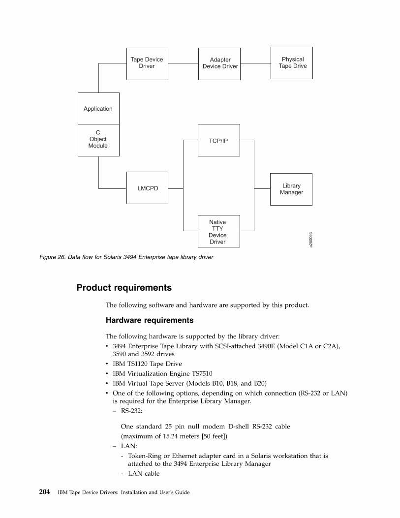
Product requirements
The following software and hardware are supported by this product.
Hardware requirements
The following hardware is supported by the library driver:v 3494 Enterprise Tape Library with SCSI-attached 3490E (Model C1A or C2A),
3590 and 3592 drivesv IBM TS1120 Tape Drivev IBM Virtualization Engine TS7510v IBM Virtual Tape Server (Models B10, B18, and B20)v One of the following options, depending on which connection (RS-232 or LAN)
is required for the Enterprise Library Manager.– RS-232:
One standard 25 pin null modem D-shell RS-232 cable(maximum of 15.24 meters [50 feet])
– LAN:- Token-Ring or Ethernet adapter card in a Solaris workstation that is
attached to the 3494 Enterprise Library Manager- LAN cable
Application
Tape DeviceDriver
AdapterDevice Driver
LMCPD
TCP/IP
NativeTTY
DeviceDriver
PhysicalTape Drive
LibraryManager
CObjectModule
a2
50093
Figure 26. Data flow for Solaris 3494 Enterprise tape library driver
204 IBM Tape Device Drivers: Installation and User's Guide

Software requirements
The following software is required for the library driver:v Solaris Operating System
Note: For information, refer to Chapter 6, “Solaris Tape and Medium ChangerDevice Driver,” on page 107.
v IBM Tape and Medium Changer Device Driver for Solaris
To obtain the most current service and documentation for this software, refer toAppendix A, “Accessing documentation and software online,” on page 327.
Software compatibility
The following optional software is supported by the library driver:
IBM Tivoli Distributed Storage Manager for Solaris
Installation instructions
The IBM tape library driver for Solaris is installed by using the standard Solarispackage facility. The IBM Tape Library Driver for Solaris is the lmcpd package.
Preinstallation considerations
The LAN or tty support must exist on the machine before the IBM Tape Librarydaemon for SunOS is installed. Install and configure the LAN or tty adapter andthe associated LAN or tty adapter device driver before you proceed with theinstallation of the lmcpd package. For information, refer to the documentationappropriate for the LAN or tty adapter and the LAN or tty adapter device driverthat you are using.
You must have root authority to complete this installation procedure.
Note: If an earlier version of the product is installed on the machine, run theuninstallation procedure before you enter the following commands. Refer to“Uninstallation procedure” on page 208 for information.
The following files are installed on the system:v /etc/lmcpd (Library Manager control point daemon)v /etc/ibmatl.conf (configuration file)v /usr/lib/libibm.o (application interface object module)v /usr/lib/libibm64.o (64-bit application interface object module)v /usr/include/sys/mtlibio.h (application interface header file)v /usr/bin/mtlib (tape library driver utility program)v /usr/bin/mtevent (tape library driver utility program)v /usr/bin/trcatl (tape library driver diagnostic program)v /opt/lmcpd (subdirectory)v /opt/lmcpd/ibmatl.conf (backup configuration file)
Note: If you are updating the lmcpd package, the existing /etc/ibmatl.conf file ispreserved. It is not overwritten. A copy of ibmatl.conf is also installed in the/opt/lmcpd directory.
Chapter 8. 3494 Enterprise Tape Library support 205

Installation procedure
Use the following commands to install the lmcpd package. Substitute the devicespecial file name for the installation source device that is appropriate for yoursystem.
If a previous version is installed on the system, uninstall the previous version first,then enter the following command,/usr/sbin/pkgrm lmcpd
To install the package from the directory where the driver is located, enter thefollowing command,/usr/sbin/pkgadd -d lmcpd.x.x.x.x
To verify that the installation was successful, enter the following command,/usr/bin/pkginfo lmcpd
Connecting the 3494 Enterprise tape library
Use one of the following methods to connect the workstation to the 3494 tapelibrary.v Use a standard 25 pin null modem D-shell RS-232 cable. Place the cable on the
native serial port or on the eight-port or 16 port asynchronous adapter.v Use a LAN connection (either Ethernet or Token-Ring) through TCP/IP.
In either case, the connection must be in place before the software is installed toensure correct initialization of the daemon.
For each 3494 tape library that is connected with an RS-232 cable, follow thedirections in “Configuring the serial port.” For each 3494 tape library that isconnected through TCP/IP, ensure that your machine has access to the LibraryManager on the Enterprise device. Use the ping utility to verify that you havenetwork connectivity to the Library Manager. Consult your network administratorif you need help with this task.
Identify the host name of your workstation to the Enterprise Library Manager.Follow the instructions in the IBM Enterprise Automated Tape Library Operator Guide,in the Add LAN Host section.
Configuring the serial port
After the 3494 tape library is connected to the workstation, you must configure theserial port to which it is connected.
Set the following tty port attributes.
Baud rate9600.
Data bits8.
Stop bits1.
Parity None.
206 IBM Tape Device Drivers: Installation and User's Guide

Defining the symbolic name to the lmcpd
After the software is installed and all tape libraries are connected to the system,the /etc/ibmatl.conf file must be edited to define the tape libraries to the lmcpd.The format of the file isSymbolic name Connection type Identifier Alternate LAN Connection
Symbolic name is used to identify each tape library. The symbolic names must beunique across all libraries that are defined in the/etc/ibmatl.conf file.
Connection type is used to define the type of connection to the library (eitherRS-232 or TCP/IP). For RS-232 connections, this type is the device special file nameof the tty device (for example, /dev/ttya or /dev/tty1). For TCP/IP connections, thistype is the IP address of the Library Manager. If the Library has a dual LAN cardthat is installed, the second IP address of the dual LAN card must be entered afterthe first IP address.
Identifier is used to specify a name by which the Library Manager identifies thehost machine. This identifier has a maximum length of 8 characters. The host nameof the workstation is usually the best name to use (although it is not necessary).This parameter is used only to identify a particular host to the 3494 EnterpriseLibrary Manager.
Alternate LAN Connection is used to specify an alternate IP address for anEnterprise High Availability LAN-attached configuration. If the High AvailabilityLibrary has a dual LAN card that is installed, the second IP address of the dualLAN card must be entered after the first alternate LAN connection IP address.
Note: For RS-232 attachments, the alternate LAN connection is not applicable.Failover for RS-232 connections proceeds over the single serial line.
The following examples show how to define the library name.3494a /dev/ttya mercury
This stanza defines the 3494a library that is connected by /dev/ttya to theworkstation. The library uses the mercury identifier for the host.3494b 9.115.32.21 jupiter
This stanza defines the 3494b library that is connected through TCP/IP to theworkstation. The address of the Library Manager on the Enterprise Tape Library is9.115.32.21. The library uses the jupiter identifier for the host.libmgrc9 9.115.46.15 telos 9.115.46.17
This stanza defines the libmgrc9 High Availability library that is connectedthrough TCP/IP to the workstation. The IP addresses of the dual Library Managersare 9.115.46.15 and 9.115.46.17.libmgrc7 9.115.32.21 9.115.32.22 mercury
This stanza defines libmgrc7 with a dual LAN card connected through TCP/IP tothe workstation. The first address of the Library Manager on the 3494 tape libraryis 9.115.32.21 and the second address is 9.115.32.22. The library uses the mercuryidentifier for the host.
The following stanza defines the libmgrc7 High Availability library with dual LANcards connected through TCP/IP to the workstation. The IP addresses of the first
Chapter 8. 3494 Enterprise Tape Library support 207

Library Manager are 9.115.32.21 and 9.115.32.22. The IP addresses of the secondLibrary Manager are 9.115.26.13 and 9.115.26.14. The library uses the mercuryidentifier for the host.libmgrc7 9.115.32.21 9.115.32.22 mercury 9.115.26.13 9.115.26.14
Adding or deleting entries in the library
You can add or delete entries in /etc/ibmatl.conf at any time. However, changes donot take effect until the daemon is started again. Use the UNIX kill command(kill -kill <pid>) to stop the lmcpd process, then enter the /etc/lmcpd commandto start the daemon again.
Ensure that the library activity on all of the libraries is completed before the lmcpdis restarted.
Uninstallation procedure
Halt all library activity before the uninstallation procedure is started. Stop thelmcpd daemon if it is running. Enter the following command to uninstall thelibrary support from your workstation./usr/sbin/pkgrm lmcpd
3494 Enterprise tape library attachment test
The following procedure tests the attachment of a 3494 Enterprise tape library to aSolaris system. The procedure assumes that your device is defined in/etc/ibmatl.conf as L3494.1. Enter a shell prompt.2. Enter mtlib -l L3494 -qI3. Enter mtlib -l L3494 -qL
Problem determination
A set of tools is provided with the software to determine whether the lmcpd isfunctioning correctly.
Error logging
The lmcpd uses the syslog facility to log the errors. Errors are logged according tothe /etc/syslog.conf file. The lmcpd uses the daemon facility for logging errors.Only errors are logged with this facility. For information about using syslog, referto your system administration manuals.
Daemon trace facility
The following trace facility is available for the lmcpd.daemon:trcatl -[ald]
Arguments:-a (trace all libraries defined in /etc/ibmatl.conf)-l <name> (name of library)-d (delete all log files; requires root authority)
Examples:
208 IBM Tape Device Drivers: Installation and User's Guide

trcatl -a >/tmp/trace-outtrcatl -l libmgrc7
Note: The -a argument takes precedence over the -l argument.
Windows
The software consists of a tape library service that communicates directly with theLibrary Manager of the 3494 Enterprise Tape Library through LAN. A utilityprogram also provides a command prompt interface to the service, and a staticlibrary and DLL that can be used to provide a communication interface with theservice.
A typical environment for the Windows Automated Tape Library Service is aworkstation that runs the Microsoft Windows operating system. It acts as a dataserver on a network with SCSI tape devices that provide backup or restore anddata server functions.
The IBM Automated Tape Library service is provided in the installation package.This service is installed with STARTUP=AUTOMATIC, which means that it isstarted when the Microsoft Windows operating system is started. An applicationprogram might access those functions through API calls. The interface is describedin the IBM Tape Device Drivers: Programming Reference. The subroutines in thismodule communicate with the Enterprise Library Manager to run the variouslibrary operations.
The service communicates with the Library Manager through TCP/IP. Thec:\winnt\ibmatl.conf configuration file is used to define the type of attachmentfor each library. Refer to “Defining the symbolic name to the service” on page 213for information.
Data flow
The software described in this chapter covers the library driver. The interfacebetween the application and the library driver is described in the IBM Tape DeviceDrivers: Programming Reference.Figure 27 on page 210 illustrates the data flow.
Chapter 8. 3494 Enterprise Tape Library support 209

Product requirements
The following hardware and software components are required and supported byIBM.
Hardware requirements
The following hardware is required for the library driver:v 3494 Enterprise Tape Library with Enterprise Tape System 3590 and 3592 drivesv IBM TS1120 Tape Drivev IBM Virtualization Engine TS7510v IBM Virtual Tape Server (Models B10, B18, and B20)
The following options are required for operation of the Enterprise LibraryManager:v Token-Ring or Ethernet adapter card in an Intel-compatible workstation that
runs Microsoft Windows and attached to the 3494 Enterprise Tape Libraryv LAN cable
Software requirements
Microsoft Windows is required for the library driver: For information, refer toChapter 7, “Windows Tape and Medium Changer device driver,” on page 149.
Figure 27. Data flow for Windows 3494 Enterprise tape library driver
210 IBM Tape Device Drivers: Installation and User's Guide

To obtain the most current service and documentation for this software, refer toAppendix A, “Accessing documentation and software online,” on page 327.
Installation instructions
The IBM tape library service for Microsoft Windows is installed by starting theinstallation binary. This binary has the format ibmatl.x.x.x.x.x86.exe for 32-bitWindows 200x that runs on x86, ibmatl.x.x.x.x.i64.exe for 64-bit Windows 2003 thatruns on IA64, and ibmatl.x.x.x.x.x64.exe for 64-bit Windows Server 2003 andWindows Server 2008 that runs on AMD64 and EM64T.
Installation procedure
Use the following procedure to install the IBM Automated Tape Library Service orto upgrade the software level of your service on your workstation.
Follow these steps to run the installation of the service and its associated software:1. Verify that the prerequisites are satisfied. Refer to “Product requirements” on
page 210.2. Ensure that the workstation is on the LAN.3. Log on as Administrator.4. If the IBM Automated Tape Library Service is installed, ensure that all
programs and services that use the service are stopped. Then, remove it fromthe system.
5. Ensure that the IBM Automated Tape Library Service is not running.v On Windows NT
a. Click Start.b. Move to Settings, then click Control Panel.c. Double-click the Services icon.
v On Windows 2000 and 2003a. Click Start.b. Move to Settings, then click Control Panel.c. Double-click the Services icon.
v On Windows 2008a. Click Start.b. Double-click the Administrative Tools icon.c. Double-click the Services icon.
The Services window opens. Scroll through the entries until you find IBMAutomated Tape Library. If you do not find the entry for IBM AutomatedTape Library, the service is not installed; click Close. If there is an entry andthe status is blank, the service is not running; click Close. If the status isStarted, click IBM Automated Tape Library, then click Stop.v Wait for the service to stop and the Status to be set to blank, then click
Close.v On 32-bit Windows 200x, wait for the service to stop and the Service status
to be set to Stopped, then close both windows.v On 64-bit Windows, the service is stopped and removed automatically
during the uninstallation.6. Obtain ibmatl driver from the IBM storage FTP server in binary.7. Locate and start ibmatl driver.
Chapter 8. 3494 Enterprise Tape Library support 211

8. You see some windows displayed that indicates the image is unpacked andread and the installation program is setting up. After these messages aredisplayed, the screen stops on a window called Welcome to the IBMAutomated Tape Library Setup Program. Follow the instructions on thewindow, then select Next.
9. The Software License Agreement window opens. Read the contents, thenclick Yes if you accept the terms. If you do not accept the terms, theinstallation script exits.
10. The Choose Destination Location window opens. You can accept the defaultdestination folder by selecting Next >, or you can select Browse... and selectanother destination folder by following the prompts in the subsequent dialog.If you do not select the default destination folder, you must record yourdestination folder for future reference. After you select the folder, click Next >.
11. The Setup Complete window opens. You can check the Yes, I want to viewthe Read Me file prompt to read the file, then click Finish, or click Finish.The Read Me file is stored in the destination file that you indicated in step 10.
12. After you click Finish, if you did not select to view the Read Me file, theinstallation dialog exits. If you chose to view the Read Me, it is displayed.After you read it, exit the Notepad application. An informational message isdisplayed, indicating that the setup is complete. Click OK to exit theinstallation dialog.
13. Verify that you can use the ping utility successfully for any tape library youwant to access from your workstation.
14. Update the c:\winnt\ibmatl.conf file, if necessary, with entries for each tapelibrary you want to access from your workstation. Refer to “Defining thesymbolic name to the service” on page 213 for details.
15. Start the service in one of the following ways:v For Windows NT, start the service by restarting the system or by using the
Services option in the Control Panel window.v On Windows 2000 and 2003, start the service by using the Services icon,
which is on the Administrative Tools icon in the Control Panel window.v On Windows 2008, start the service by using the Services icon, which is on
the Administrative Tools icon.
Note: When a firewall is enabled on Windows, you must allow the lmcpdprogram to access the network. Do not block the network IP port of 3494,which is used for communication between the 3494 library and lmcpd.
For example, to allow lmcpd.exe access to the network on Windows 2008servers, click the Windows Firewall icon in the Control Panel window. Next,click the button to allow a program or an exception, and then click AddProgram. Select your browser and then select lmcpd.exe in/Windows/system32 for an x86 system or /Windows/SysWOW64 for i64 orx64 systems.
Connecting the 3494 Enterprise tape library
Use a LAN connection (either Ethernet or Token-Ring) through TCP/IP to connectthe workstation to the 3494 Enterprise tape library. The connection must be inplace before the service is started to ensure correct initialization of the service.
212 IBM Tape Device Drivers: Installation and User's Guide

Ensure that your machine has access to the Library Manager on the Tape Library.Use the ping utility to verify that you have network connectivity to the LibraryManager. Consult your network administrator if you need help with this task.
Identify the host name of your workstation to the Enterprise Library Manager.Follow the instructions in the IBM Enterprise Automated Tape Library Operator Guide,in the Add LAN Host section.
Defining the symbolic name to the service
After the software is installed and the tape libraries are connected to the system,the c:\winnt\ibmatl.conf file must be edited to define the tape libraries to theservice. The format of the file isSymbolic name Connection type Identifier Alternate LAN Connection
Symbolic name identifies each tape library. The symbolic names must be uniqueacross all libraries that are defined in the c:\winnt\ibmatl.conf file.
Connection type is the IP address of the Library Manager. If the Library has a dualLAN card that is installed, the second IP address of the dual LAN card must beentered after the first IP address.
Identifier specifies a name by which the Library Manager identifies the hostmachine. This identifier has a maximum length of 8 characters. The host name ofthe workstation is usually the best name to use (although it is not necessary). Thisparameter identifies only a particular host to the Enterprise Library Manager.
The following stanza defines the 3494b library that is connected through TCP/IP tothe workstation. The address of the Library Manager on the 3494 tape library is9.115.32.21. The library uses the jupiter identifier for the host.3494b 9.115.32.21 jupiter
The Alternate LAN Connection parameter specifies an alternate IP address for anEnterprise High Availability LAN configuration. If the High Availability Libraryhas a dual LAN card that is installed, the second IP address of the dual LAN cardmust be entered after the first alternate LAN connection IP address.
The following stanza defines the libmgrc9 High Availability library that isconnected through TCP/IP to the workstation. The IP addresses of the dualLibrary Managers are 9.115.46.15 and 9.115.46.17.libmgrc9 9.115.46.15 telos 9.115.46.17
The following stanza defines libmgrc7 with a dual LAN card connected throughTCP/IP to the workstation. The first address of the Library Manager on the 3494tape library is 9.115.32.21 and the second address is 9.115.32.22. The library usesthe mercury identifier for the host.libmgrc7 9.115.32.21 9.115.32.22 mercury
The following stanza defines the libmgrc7 High Availability library with dual LANcards connected through TCP/IP to the workstation. The IP addresses of the firstLibrary Manager are 9.115.32.21 and 9.115.32.22. The IP addresses of the secondLibrary Manager are 9.115.26.13 and 9.115.26.14. The library uses the mercuryidentifier for the host.libmgrc7 9.115.32.21 9.115.32.22 mercury 9.115.26.13 9.115.26.14
Chapter 8. 3494 Enterprise Tape Library support 213

Adding or deleting libraries to the service
You can add or delete entries in c:\winnt\ibmatl.conf at any time. However,changes do not take effect until the tape service starts again.
On Windows NT, stop and start the service by using the Services option in theControl Panel window.
On Windows 200x, stop and start the service by using the Services icon, which ison the Administrative Tools icon in the Control Panel window.
Ensure that the library activity on all of the libraries is completed before theservice is started again.
Uninstallation procedure
Use the following procedure to remove the IBM Automated Tape Library Servicepermanently from your workstation.
Note: If you are upgrading the software level of your service, follow the steps in“Installation procedure” on page 211.
Follow these steps to uninstall the service and its associated software:1. Log on as Administrator.2. Back up the c:\winnt\ibmatl.conf file if you want to keep a copy of this file
because the uninstall procedure erases the file.3. Ensure that all programs and services that use the IBM Automated Tape
Library Service are stopped.4. Ensure that the IBM Automated Tape Library Service is not running. Click
Start > Settings > Control Panel.v Double-click the Services icon.v On Windows 200x, double-click the Administrative Tools icon, then
double-click the Services icon.The Services window opens. Scroll through the entries until you find IBMAutomated Tape Library. If the status is blank, the service is not running;click Close. If the status is Started, click IBM Automated Tape Library, thenclick Stop.v Wait for the service to stop and the Status to be set to blank, then click
Close.v On 32-bit Windows 200x, wait for the service to stop and the Service status
to be set to Stopped, then close both windows.v On 64-bit Windows, the service is stopped and removed automatically
during the uninstallation.5. Open a Command Prompt window, enter lmcpd -remove, press Enter, then
wait for the command to complete.
Note: If you forget this step, the next time that the system is started,Microsoft Windows NT tries (unsuccessfully) to start the service again. Toresolve this situation, you must reinstall the service, then uninstall it.
6. Double-click Add/Remove Programs in Windows NT/200x or Programs andFeatures on Windows 2008 in the Control Panel window.
7. Scroll to and select IBM Automated Tape Library.
214 IBM Tape Device Drivers: Installation and User's Guide

8. For Windows 200x, click Change/Remove.9. A Confirm File Deletion window opens. Click Yes.
10. After various dialogs run, a Remove Programs from Your Computer windowopens, which indicates the components that were removed successfully. ClickOK to exit the dialog.
11. For Windows 2000 and 2003, close the Add/Remove Programs Propertieswindow.For Windows 2008, close the Programs and Features window.
3494 Enterprise tape library attachment test
The following procedure tests the attachment of a 3494 Enterprise tape library to aWindows system. The procedure assumes that your device is defined inc:\winnt\ibmatl.conf as L3494.1. Open a Windows command shell window.2. Enter mtlib -l L3494 -qI3. Enter mtlib -l L3494 -qL
Problem determination
A tracing tool is provided with the software to determine whether ibmatl isfunctioning correctly.
Daemon trace facility
The following trace facility is available for the ibmatl service.trcatl -husage: trcatl [-ald]
[-l <name>] name of library[-a] all libraries defined in c:\WINNT\ibmatl.conf[-d] delete all logfiles in c:\WINNT\
Note:
1. Run trcatl in the Command Prompt window.2. The -a parameter takes precedence over the -l parameter.3. The trace.out is located under the directory where the trcatl runs.
Examples:trcatl -l libmgrc7trcatl -a > trace.out
Chapter 8. 3494 Enterprise Tape Library support 215

216 IBM Tape Device Drivers: Installation and User's Guide

Chapter 9. IBM Tape Diagnostic Tool (ITDT)
This chapter describes the IBM Tape Diagnostic Tool.
Purpose
The IBM Tape Diagnostic Tool (ITDT) is available in two versions:v Standard Edition (ITDT-SE) - The command line version.v Graphical Edition (ITDT-GE) - The GUI version for the following platforms:
– Microsoft Windows operating systems– Linux operating systems
Both versions provide the user with a single diagnostic program for tapeutilapplications. Both SE and GE contain tapeutil functions with SE also providingscripting capability.
Note: The term tapeutil is a synonym for the tool that is delivered with the devicedriver. For example, this tool is named tapeutil on UNIX operating systems; it isnamed ntutil on Microsoft Windows operating systems.
The available advanced operations that are provided by the IBM Tape DiagnosticTool is completed on tape drives and tape libraries. By using this function, you cancomplete maintenance tasks and run diagnostic tasks to determine tape driveissues. This action reduces product downtime and increases productivity.
The IBM Tape Diagnostic Tool is designed tov Run quick or extended diagnostic tests on tape drivesv Start tape library self-test operationsv Retrieve dumps from tape drives and librariesv Run a firmware update on tape drives or librariesv Online Check for Firmware updates for tape drives or libraries (ITDT-GE)v Test the performance of the environment by completely writing a cartridge and
measuring performancev Verify tape drive compressionv Measure system performancev Retrieve and display cartridge usage informationv Verify the encryption environment
This test is used to verify whether data on the cartridge was written encrypted.v Scan the system to discover all supported tape and library devices.v Run a connection test (scan)
This test is used to verify that all devices are attached properlyv Run a standard test to check whether the tape device is defective and output a
pass/fail result
Note: When this test is completed, all data on the cartridge is overwritten.v Run a full write function
© Copyright IBM Corp. 2007, 2015 217
This function writes the entire cartridge, overwriting all previous data with aselectable block size that contains either compressible or incompressible data andthen outputs performance data.
Note: When this test is completed, all data on the cartridge is overwritten.v Run a system test
Write different block sizes with compressible and incompressible data and thenoutputs performance data.
Note: When this test is completed, all data on the cartridge is overwritten.v Run a tape usage function to retrieve statistical data and error countersv Run HD-P functions like discovery.v Physical Copy/Data migration and verification of cartridges.v Log and Dump File analysis.
ITDT-SE provides the most important functions of the previous tapeutil tools. Asan extension of the current tapeutil variants, the set of operations and functionsavailable with ITDT-SE is identical across all supported operating systems (unless afunction is not available on a particular system).
Dedicated device drivers for tapes and libraries can be installed on the targetsystem and an application is installed that uses the tape/library devices. When thisconfiguration exists, ITDT-SE can coexist with the application so that when theapplication disables the device internally, ITDT-SE can run the diagnostic tests onthat device.
Accessing ITDT
IBM maintains the latest levels of the ITDT tool chain and documentation on theInternet at http://www.ibm.com/support/fixcentral.
One option to access ITDT is through Appendix A, “Accessing documentation andsoftware online,” on page 327. When an IBM driver is downloaded, there is acorequisite to download ITDT.
This portal gives access to the download area where the following procedureguides you to the correct download:1. In the Product Group menu select Storage Systems.2. In the Product Family menu select Tape Systems.3. In the Product Type menu select Tape device drivers and software.4. In the Product menu select Tape Diagnostic Tool (ITDT).5. Select your platform and press Continue.
Supported systems
ITDT is supported on the following systems.
Standard Edition (ITDT-SE)
The Standard Edition (ITDT-SE) is supported on the following operating systems.v AIX operating systems (64-bit pSeries/System p)
218 IBM Tape Device Drivers: Installation and User's Guide
– AIX 5L 5.3– AIX 6.1– AIX 7.1
v HP-UX operating systems– HP-UX Version 11i v1, v2 and v3 (64-bit PA-Risc and Itanium)
v Linux operating systems– Linux systems with Kernel 2.6, glibc 2.2.5 and later (32-bit x86)– Linux systems with Kernel 2.6, glibc 2.3.2 and later (64-bit x64)– Linux systems with Kernel 2.6, glibc 2.2.5 and later (64-bit pSeries/System p)– Linux systems with Kernel 2.6, glibc 2.3.3 and later (64-bit zSeries/System z)
v Macintosh OS X– Mac OS X 10.5.6 and later (Leopard) (Intel, 32-bit)– Mac OS X Server 10.5.6 and later (Intel, 32-bit)– Mac OS X 10.6 (Snow Leopard) and later (Intel, 32 and 64-bit)– Mac OS X Server 10.6 and later (Intel, 32 and 64-bit)– Mac OS X 10.7.5 Mac Pro (Intel, 64-bit)– Mac OS X 10.8.4 Mac Pro (Intel, 64-bit)– Mac OS X 10.9.5 Mac Pro (Intel, 64-bit)– Mac OS X 10.10.3 Mac Pro (Intel, 64-bit)
v Solaris operating systems– Solaris Version 9 and 10 (64-bit SPARC and 64-bit x64)– Solaris Version 11.1 (64-bit SPARC)
v Windows operating systems– Microsoft Windows Server 2008 (32-bit x86 and 64-bit x64)– Microsoft Windows 2012 (32-bit x86 and 64-bit x64)– Microsoft Windows 7 (32-bit x86 and 64-bit x64)– Microsoft Windows 8 (32-bit x86 and 64-bit x64)
v i5/OS™ V5R4, IBM i 6.1 and IBM i 7.1 (iSeries/System i®)
Graphical Edition (ITDT-GE)
The Graphical Edition (ITDT-GE) is supported on the following operating systems.v Windows operating systems
– Microsoft Windows Server 2008 (32-bit x86 and 64-bit x64)– Microsoft Windows 2012 (32-bit x86 and 64-bit x64)– Microsoft Windows 7 (32-bit x86 and 64-bit x64)– Microsoft Windows 8 (32-bit x86 and 64-bit x64)
v Linux operating systems– Linux Distributions with Kernel 2.6, glibc 2.2.5 and later (32-bit x86 and 64-bit
x64).
Chapter 9. IBM Tape Diagnostic Tool (ITDT) 219
|
|
|
|
|
|
|
|
|
|
|
|

Supported equipment
The following equipment is supported for both the Standard Edition (ITDT-SE) andthe Graphical Edition (ITDT-GE):v IBM Ultrium 3580 Tape Drive (Generation 3, 4 and 5)v IBM Ultrium Tape Drives T800/F, T800V, T1600/F, T3000V/Pv IBM 3588/TS1030 model F3A and F3B Tape Drivev IBM 3588/TS1060 model F6A Tape Drivev IBM 3580 Half Height/TS2230 and TS2240 Tape Drive Expressv IBM TS2250 Tape Drivev IBM TS2260 Tape Drivev IBM TS2270 Tape Drivev IBM TS2340 Tape Drive Expressv IBM TS2350 Tape Drivev IBM TS2360 Tape Drivev IBM 3592/TS1120/TS1130/TS1140/TS1150 Enterprise Tape Systemv IBM 3572/TS2900 Tape Library Expressv IBM 3573/TS3100 and TS3200 Tape Library Expressv IBM 3576/TS3310 Tape Libraryv IBM 3577/TS3400 Tape Libraryv IBM 3584/TS3500 and TS4500 Tape Library
The following equipment is supported System x LTO tape drives. These drives arenot tested by the IBM Test Lab. They are also not supported by IBM support. Allqueries are to be addressed to IBM System x support.v IBM Full Height LTO Gen 1, p/n 00N8016, replacement p/n 37L5799v IBM Full Height LTO Gen 2, p/n 59P6744, replacement p/n 71P9141v IBM Full Height LTO Gen 3, p/n 25R0012 and 39M5657, replacement p/n
25R0003 and 23R4808v IBM Half Height LTO Gen 3, p/n 43W8478, replacement p/n 23R7036v IBM Half Height LTO Gen 4, p/n 44E8895, replacement p/n 45E1125v IBM Half Height LTO Gen 5v 3600-XXX Library and Autoloader IBM Full Height LTO Gen 1, p/n 09N4048v 4560-SLX IBM Full Height LTO Gen 2, p/n 71P9146v 3623-2LX IBM Full Height LTO Gen 2v 3361-4LX IBM Full Height LTO Gen 3 SCSI (p/n 42C3942 and 40K2573) and
Fibre (p/n 40K2575)*v 3362-2LX IBM Full Height LTO Gen 3 SCSI (p/n 40K2596) and Fibre (p/n
42D8769)*
All other System x LTO tape drives are not supported by ITDT.
Note: Replacement part numbers are only given for the stand-alone IBM LTO tapedrives.
For i5/OS operating systems, see “i5/OS operating systems” on page 230 forproduct support limitations.
220 IBM Tape Device Drivers: Installation and User's Guide
|

IBM Tape Diagnostic Tool - Standard Edition
Installing ITDT - Standard Edition
This section describes the installation procedures for the Standard Edition of ITDTin various operating systems.
Before the IBM Tape Diagnostic Tool Standard Edition (ITDT-SE) is used with theIBM Tape Device Driver, we recommend upgrading to the latest available IBMTape Device Driver level.
In a System Managed Encryption setup, the Encryption test [E] always exits withNO DRIVER SPECIAL FILE when ITDT-SE is started with -force-generic-dd.
Installing ITDT-SE on Microsoft Windows operating systems
To install ITDT-SE on Microsoft Windows operating systems, complete thefollowing steps.
Note: ITDT-SE can be used only by a user with administrator rights.1. Download install_itdt_se_Windows<arch>_<version>.exe where <arch> can bev AMD64 (64-bit Intel EM64T or AMD servers)v X86 (32-bit Intel-compatible servers)
to a directory of your choice.2. Run the following command:
install_itdt_se_Windows<arch>_<version>.exe
Installing ITDT-SE on i5/OS operating systems
ITDT-SE for i5/OS or IBM i is installed with a graphical installer based on theInstallAnywhere installation software. This software must be run on a MicrosoftWindows system and installs the software onto the remote i5/OS system. Theinstaller generates installation information on the local Microsoft Windows system.So, the program can be removed from the remote i5/OS system by running theuninstaller on the local Microsoft Windows system.
To install ITDT-SE on i5/OS operating systems, complete the following steps.
Note: ITDT-SE on i5/OS requires a Microsoft Windows PC with a Java™ run time1.4.2 or higher.1. Start the installer installi5OS_ITDT_SE_<version>.exe.2. Read through the welcome and license screens.
Chapter 9. IBM Tape Diagnostic Tool (ITDT) 221
|
|

3. Accept the License Agreement, then click Next.
4. Enter your i5/OS system host name or IP address and administratorcredentials. Start the installation by pressing Install. Click Done when theinstallation is complete.
a2500246
Figure 28. Welcome/Startup screen
a2500247
Figure 29. License screen
222 IBM Tape Device Drivers: Installation and User's Guide

Note: The user name must be QSECOFR.
a2500248
Figure 30. Machine credentials screen
a2500249
Figure 31. Installation progress screen
Chapter 9. IBM Tape Diagnostic Tool (ITDT) 223
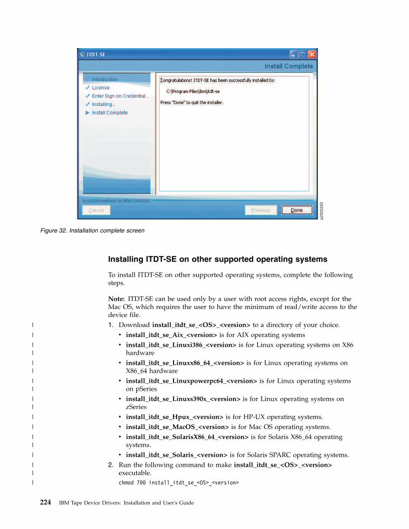
Installing ITDT-SE on other supported operating systems
To install ITDT-SE on other supported operating systems, complete the followingsteps.
Note: ITDT-SE can be used only by a user with root access rights, except for theMac OS, which requires the user to have the minimum of read/write access to thedevice file.1. Download install_itdt_se_<OS>_<version> to a directory of your choice.v install_itdt_se_Aix_<version> is for AIX operating systemsv install_itdt_se_Linuxi386_<version> is for Linux operating systems on X86
hardwarev install_itdt_se_Linuxx86_64_<version> is for Linux operating systems on
X86_64 hardwarev install_itdt_se_Linuxpowerpc64_<version> is for Linux operating systems
on pSeriesv install_itdt_se_Linuxs390x_<version> is for Linux operating systems on
zSeriesv install_itdt_se_Hpux_<version> is for HP-UX operating systems.v install_itdt_se_MacOS_<version> is for Mac OS operating systems.v install_itdt_se_SolarisX86_64_<version> is for Solaris X86_64 operating
systems.v install_itdt_se_Solaris_<version> is for Solaris SPARC operating systems.
2. Run the following command to make install_itdt_se_<OS>_<version>executable.chmod 700 install_itdt_se_<OS>_<version>
a2500250
Figure 32. Installation complete screen
224 IBM Tape Device Drivers: Installation and User's Guide
|
|
||
||
||
||
|
|
||
|
||
|

3. To run without parameters, run the following commandinstall_itdt_se_<OS>_<version>
or./install_itdt_se_<OS>_<version>
depending on your operating system.
Optionally you can use these parameters:v -h [--help] Show help messagev -v [--verbose] Print the extracted filesv -p [--path] Path for extraction (default is current directory)v -t [--test] Show package content
Starting ITDT - Standard Edition
This section describes the startup procedures for the Standard Edition of ITDT invarious operating systems.
Starting ITDT-SE on Solaris operating systems1. If the IBM Tape Device Driver is not used, if it is not installed, or you want to
be able to run -force-generic-dd, configure the sgen driver.A script sgen_solaris_conf.sh is included in the ITDT-SE package. This scriptallows you to configure the sgen generic SCSI driver that is shipped withSolaris.ITDT-SE requires that the sgen device driver is configured so that the devicesyou want to work with can be found.
Note: For system security reasons, always reset the sgen device driver settingsafter you finish working with ITDT-SE, by using the sgen_solaris_conf.shscript.To configure the sgen driver, start the sgen_solaris_conf.sh script with rootaccess.The following command-line options are available on the SGEN driverconfiguration screen:v 1. Check driver: This option checks if the driver /kernel/drv/sgen is available.v 2. List driver settings: This option shows the current activated devices.v 3. New driver configuration: This option shows the screen that is used to
create a new driver configuration (see Step 2).v 4. Stop sgen driver: This option stops the driver (that is, rem_drv sgen).v 5. Start sgen driver: This option stops and starts the sgen driver.v 6. Exit program: This option closes the shell script.
2. Enter option 3 to create a new driver configuration.The following command-line options are available on the New Configurationscreen. Use these options to configure the sgen driver:v 1. List targets: This option shows the targets in current configuration.v 2. Define device types: This option defines drive and changer types.v 3. or 5. Add targets: This option adds targets to the list.
Chapter 9. IBM Tape Diagnostic Tool (ITDT) 225
|
|
|
|
|
|
|
|
|
|
|

Note: Option 3 allows for the addition of individual devices one at a time.Option 5 allows for the addition of a range of devices, eliminating the needto add many devices one by one.
v 4. or 6. Remove targets: This option removes targets from the list.
Note: Option 4 allows for the removal of individual devices one at a time.Option 6 allows for the removal of a range of devices, eliminating the needto remove many devices one by one.
v 7. Save configuration: This option saves the modifications.v 8. Back to Main Menu: This option returns to the main menu.
3. After the sgen driver is configured, enter command-line option 8 to go back tothe main menu.
4. On the SGEN driver configuration screen, enter command-line option 5. Thisoption starts the sgen driver. New devices are found by using the definitionsthat are completed in Step 2.
5. After the new devices are found, enter option 6 to exit the sgen_solaris_conf.shscript.
Note: For Fibre Channel Host Bus Adapters (HBAs), special handling is required.Attached devices must be configured with their WWPN in the sgen.conf file. Thistask must be done manually. It is not completed by using thesgen_solaris_conf.sh script.
The following code is an example how to add those devices:Run the command "cfgadm -al" to get the WWPN number(s).
......c4 fc-private connected configuredc4::5005076302401924 tape connected configured.....Add the WW-PN number(s) into the sgen.conf file.
name="sgen" parent="fp" target=0 lun=0 fc-port-wwn="5005076302401924";name="sgen" parent="fp" target=0 lun=1 fc-port-wwn="5005076302401924";
If you have finished the editing, the sgen driver has to be restarted.Please enter "update_drv sgen".
The Read Attribute command is 16-byte CDB. On Solaris 10, IBMtape can detectwhat maximum CDB length is supported from HBA attributes and set thesupported CDB. For Solaris 9, CDB16 must be enabled for ITDT-SE to workcorrectly. This procedure can be done by adding the entry ofcdb16_support=1
at the first line in/usr/kernel/drv/IBMtape.conf
and reload the IBMtape driver again.
To start ITDT-SE, run the following command:./itdt
At first start, read the User License Agreement.v Press Enter to scroll the license screens forward or b followed by Enter to go
back.v Type i if you agree to the terms of license or q followed by Enter to quit the
application.
226 IBM Tape Device Drivers: Installation and User's Guide

During the initial program start, the input and output directories are created.v Input directory: default directory for firmware files during Firmware Updatev Output directory: directory that contains the result files, dump files, and log files
after tests are run
ITDT-SE does not make changes outside the installation directory.
Starting ITDT-SE on Windows operating systems
At first program start, the license text is displayed and the input and outputdirectories are created. Start ITDT by running the following command from thedirectory "ITDT" that was created during the installation (confirm to run withadministrator rights):itdt.exe
Read the User License Agreement.v Press Enter to scroll the license screens forward or b followed by Enter to go
back.v Type i, if you agree to the terms of license or q followed by Enter to quit the
application.
ITDT-SE does not create any registry entries or make changes outside theinstallation directory.
During installation a subdirectory "ITDT" was created which contains the ITDTprogram file and 2 subdirectories initially:v "License" directory with license files in different languages.v "Scripts" directory for extra scripts.
When the program is run for the first time, two more subdirectories are created inthe "ITDT" folder:v "Input" directory for firmware files to be uploaded to devices.v "Output" directory for generated log and dump files.
To remove ITDT from your system, erase the ITDT directory. Any log and dumpfiles in the subdirectories are also erased when you do so.
Starting ITDT-SE on i5/OS operating systems
To use ITDT-SE to update firmware or pull dumps from a tape drive inside a tapelibrary, make sure that the drives are varied online in STANDALONE MODE bycompleting the following steps.1. Issue the command WRKMLBSTS. Identify the library and drives you want to
work with. Note their names (for example, TAPMLB01, TAP01, TAP02).2. Deallocate the corresponding drives by using option 6.3. Vary OFF the TAPMLB by using option 2.4. Enter the following command:
WRKCFGSTS *DEV TAP*
Identify the drives that were noted in Step 1 (for example, TAPMLB01, TAP01,TAP02) and vary them ON by using option 1.
5. Start the iSeries Qshell environment with the following command:QSH
Chapter 9. IBM Tape Diagnostic Tool (ITDT) 227
||||
||
|
|
||
|
|
||
6. Change to the folder /home/ITDT with the following command:cd /home/ITDT
7. Start ITDT with the following command../itdt
8. Update Firmware and pull dumps. See “Firmware Update” on page 240 and“Dump” on page 240.
9. When firmware updates and dumps are complete, enter the followingcommand:WRKCFGSTS *DEV TAP*
10. Vary off the TAPs that you worked with by using option 2.11. Issue the command WRKMLBSTS. Identify the library and drives you worked
with.12. Vary on the TAPMLB by using option 1.13. Press F5 to refresh the screen. The TAPs belonging to the TAPMLB shows up.14. Allocate the TAPs back to the TAPMLB by using option 4 or 5.
Starting ITDT-SE on other supported operating systems
To start ITDT-SE, run the following command./itdt
At first start, read the User License Agreement:v Press Enter to scroll the license screens forward or b followed by Enter to go
back.v Type i, if you agree to the terms of license or q followed by Enter to quit the
application.
During the initial program start, the input and output directories are created.v Input directory: default directory for firmware files during Firmware Updatev Output directory: directory that contains the result files, dump files, and log files
after tests are run
ITDT-SE does not make changes outside the installation directory.
Standard Edition - known issues and limitations
This section describes the known issues and limitations of the ITDT-SE program.
AIX operating systems
The following are the known scan limitations:v Only devices that have the device state "available".
For FC and SAS devices, ID and LUN greater than 999 are not displayed; they areshown as ###.
When logged in through telnet, backspace might not work - an escape sequence isinserted and the input is ignored after Enter is pressed.
228 IBM Tape Device Drivers: Installation and User's Guide
|
|
|
HP-UX operating systems
Verify that the following patches are installed before ITDT-SE is started.v PA-Risc: At least these patches:
– ld and linker tools cumulative patch– libc cumulative patch
v Itanium/IA-64: All regular patches and the following patches:– VxVM 3.5~IA.014 Command Patch– VxVM 3.5~IA.014 Kernel Cumulative Patch– Aries cumulative patch– linker + fdp cumulative patch
Note: ITDT-SE is emulated by Aries (a binary emulator that transparently emulates32-bit and 64-bit HP-UX PA-RISC applications on HP-UX IA-64 machines).
On HP-UX11.iV3 systems, tape libraries that are operated through the drive'scontrol path (no control path failover) might disappear from the Device List after a[F] Firmware Update on the controlling drive. It is recommended to completerepeated [S] Scan operations to make the library reappear in the device list.
Linux operating systems
ITDT-SE on Linux requires glibc 2.2.5 or later.
Note: On an SLES9 s390x (64 bit) configuration, you might experience a SCSICMD TIMEOUT when the [T] option is run with the IBM Tape Device Driver.
For SUSE SLES9 on zSeries, ensure that the kernel update SUSE-SA:2007:035 isinstalled.
Solaris operating systems
Rescan might take 6-8 minutes, depending on the numbers of host adapters anddevices attached.
The known scan limitations: SCSI ID 0-255, LUN 0-10.
If the IBM Tape Device Driver is not installed on Solaris 10, tape devices might notbe found during scan although they are configured in sgen.conf. When this eventoccurs, complete the following steps to configure the devices:1. Check the current driver bindings for IBM tape drives and changers by
entering the following commands:# egrep "scsiclass,01" /etc/driver_aliases (for drives)# egrep "scsiclass,08" /etc/driver_aliases (for changers)
2. Modify the /etc/driver_alias file to comment all lines not starting with sgenand containing identification of your drives and changers. Examples:#st "scsiclass,01" (all tape drives)#st "scsiclass,01.vIBM.pULT3580-TD4" (IBM tape drive model ULT3580-TD4)#st "scsiclass,08" (all changers)#st "scsiclass,08.vIBM.p3573-TL" (IBM changer model 3573-TL)
3. Check that the configured drives are not configured for st driver by enteringthe following command:# cfgadm -al
Chapter 9. IBM Tape Diagnostic Tool (ITDT) 229

If the tape drive is claimed by st device driver, an entry with cxx:rmt/y, isdisplayed, for example:c11::rmt/0 tape connected configured unknown
4. Add sgen driver aliases with one of the following commands:# update_drv -a -i ’"scsiclass,01.vIBM.pULT3580-HH4"’ sgen
(adds sgen alias for IBM drive, model ULT3580-HH4)
# update_drv -a -i ’"scsiclass,01"’ sgen(adds sgen alias for all drives attached to the system)
# update_drv -a -i ’"scsiclass,08.vIBM.pULT3581-TA2"’ sgen(adds sgen alias for IBM changer, model ULT3581-TA2)
# update_drv -a -i ’"scsiclass,08"’ sgen(adds sgen alias for all changers attached to the system)
5. Check that the drives and changers are now configured with the followingcommand:# cfgadm -al
6. If the drives or changers are not listed in the output of ’cfgadm -al’, rebootthe system and verify the list of configured devices with the command:# cfgadm -al
Windows operating systems
After a firmware update, devices might disappear. This issue is a known Windowsproblem.
See the Article ID: 812024 at http://support.microsoft.com/kb/812024/en-us.
Repeated Scan operations can help to rediscover the device.
When applications are turned on Windows while ITDT-SE is running, an extra ESCcharacter might appear on the input line. When this issue occurs, the input isignored after Enter is pressed.
If you are using Adaptec SCSI Host Bus adapters, ensure that you are using thelatest Adaptec Host Bus Adapter Drivers instead of the drivers that are shippedwith the Windows operating system.
On Microsoft Windows systems where the maximum transfer size is limited to lessthan 64 kB, the Dump and Firmware Update operations do not work.
i5/OS operating systems
The Tape Drive must be varied online. If the tape drive is operated through a tapelibrary, the library must be varied offline. See “Starting ITDT-SE on i5/OSoperating systems” on page 227 for details.
As the library is varied offline, the Encryption Test does not deliver decrypted datain a Library Managed Encryption environment.
IO adapters without a dedicated IOP do not support commands with 16 bytes.These adapters are called IOP-less and can be identified with the command;WRKHDWRSC *STG. Adapters where the CMBxxx and DCxxx resource names are thesame (like both 5774) are IOP-less. If it is IOP, then the CMBxxx is a different typefrom the DCxxx.
230 IBM Tape Device Drivers: Installation and User's Guide

Therefore, the following ITDT commands and test sequences can fail on IOP-lessadapters attached devices.v Encryption Verification Testv Physical Copy with more than one partitionv Erase commandv Change Partition commandv Read/write -attribute command
ITDT-SE on i5/OS V5R4 requires the following PTF installed.v PTF: SI25023 Release: 540 Abstract: OSP-MEDIA-TAPE-THREADS-MSGCEE0200-
T/QTAHRMGR QTARDCAP FAILS
The [U] Tapeutil option is not available for i5/OS with this release as all theunderlying operations require the IBM Tape Device Driver to be installed.
FC 5912 SAS HBA support is only for POWER6 and V6R1 configurations that areattached to LTO Gen 4 HH tape drives (No support for LTO 3 HH SAS).
All supported operating systems
This section describes the known issues and limitations of the ITDT-SE program onall other supported operating systems.
Prevent/Allow Medium Removal is missing as a Tape Drive option. But, it can stillbe completed by using the [56] Prevent/Allow Medium Removal option for tapelibraries while the tape device is opened.
User Interface issues
If you press the arrow keys on most UNIX operating system consoles, the input isignored after Enter is pressed.
When the Tab key is pressed as an input string for field data, the user interface iscorrupted.
Make sure that field input does not start with a number followed by space andextra text. This input is interpreted as an entry to a specific row in the field. Toavoid this issue, use an underscore character ( _ ) instead of the space character.
Command timeout
There is no instant operation termination upon SCSI command timeout; forexample, when the SCSI cable is unplugged after POST A is started.
When a command timeout condition occurs, ITDT might still continue to completemore operations (like unmounting the cartridge) instead of instantly terminatingwith a timeout condition.
3576/TS3310 tape library
Library Firmware Update with ITDT-SE and ITDT-GE is not supported by the3576/TS3310 library. Update the Firmware by using the 3576/TS3310 Web UserInterface.
Chapter 9. IBM Tape Diagnostic Tool (ITDT) 231

3494 tape library
Drives in a 3494 tape library or an STK silo library are supported, only the [T]Test option does not work because of device-specific restrictions for handlingcartridges.
Standard Edition - Start menu commands
After program startup, ITDT-SE displays the start screen menu.
The following commands are available on the start screen menu:v [S] Scan for tape drives and enter Diagnostic/Maintenance Mode
Opens the screen for the Scan function (refer to “Standard Edition - Scan menucommands” on page 233).
v [H] HelpHelp starts and displays the available online help.
v [Q] Quit programQuits the program.
v [U] TapeutilOpens the screen for the Tapeutil operation commands. These commands are thestandardized tapeutil functions with most of the options available that wereavailable with the previous tapeutil functions (refer to “Standard Edition -Tapeutil menu commands” on page 252).
v [A] Add Device ManuallyOpens the screen for specifying a device manually instead of using the Scanfunction.
a2500231
Figure 33. Start screen menu
232 IBM Tape Device Drivers: Installation and User's Guide
|
|

Standard Edition - Scan menu commands
When ITDT-SE is used after S is entered on the start screen, the Scan functionstarts and displays the first device list screen.
To select a device, enter a number from the leftmost column, then click Enter.
Entering the M command returns to the Start Screen menu. Entering the Vcommand toggles between displaying the physical device address and the drivername.
a2500295
Figure 34. Scan screen menu
Chapter 9. IBM Tape Diagnostic Tool (ITDT) 233
|

This screen contains the S, T, D, F, Y, J, and A commands. Entering the Ocommand displays the second device list screen. The second screen contains the W,U, K, L, I, E, C, and R commands.
The following commands are described:v S - “Scan” on page 235v T - “Health Test” on page 237v D - “Dump” on page 240v F - “Firmware Update” on page 240v Y - “System Test” on page 243v J - “Eject Cartridge” on page 244v A - “Cleaning Statistics” on page 244v O - “Other Functions” on page 245
a2500271
Figure 35. Scan screen second menu
234 IBM Tape Device Drivers: Installation and User's Guide
|
|
|
|

v W - “Full Write” on page 245v U - “Tape Usage” on page 247v K - “Check LTFS Readiness” on page 247v L - “Library Test” on page 248v I - “Library Media Screening” on page 248v E - “Encryption” on page 249v C - “Configure TCP/IP” on page 251v R - “Return” on page 252
Scan
The Scan function [S] is used to discover all supported tape and library devicesthat are attached to the computer system so that they can be selected for thesubsequent ITDT-SE operations. The scan function also serves as a connection testthat can be used to verify correct attachment of the devices.
Make sure that no other program is accessing the devices that are used byITDT-SE. For example, stop the backup jobs that are accessing the devices whenITDT-SE is used, or if not sure, stop the entire backup application.
After ITDT-SE is started, type S followed by Enter to activate the scan function.
Depending on the operating system and the number of attached drives, the scancan take several minutes. See “Standard Edition - known issues and limitations” onpage 228 for details.
During the scan operation, a bar in the lower left edge of the screen shows that thescan operation is still in progress.
When the scan is finished, the first device list screen is displayed.
a2500270
Figure 36. More scan options
Chapter 9. IBM Tape Diagnostic Tool (ITDT) 235
|

The first device list screen shows all detected devices and the connectioninformation (host adapter number, bus number, SCSI/FCP ID, and LUN or drivername) along with product data (Model name, Unit Serial number, Microcoderevision). For drives that are attached to a library, the Changer column shows theserial number of the changer the drive is attached to.
Scrollable data is indicated by "VVVVVVVVV" in the bottom border of the table.To view the non-displayed entries, type + and press Enter.
Note: For fast down scrolling, type + followed by a space and the number of linesto scroll down, then press Enter. Alternately, type N and press Enter to scroll downone page.
To scroll back, use - instead of +.
Note: For fast up (backward) scrolling, type - followed by a space and the numberof lines to scroll up. Press Enter, or type P and press Enter to scroll up one page.
If no devices appear or if devices are missing in the list, make sure thatv ITDT-SE is running with administrator/root rights.v The devices are properly attached and powered on.v Linux: The devices must be attached at boot time.v i5/OS: Only tape drives are detected.v Solaris, when no IBM tape device driver is in use:
– Ensure that sgen is correctly configured.file /kernel/drv/sgen.conf
is correctly configured (see “Starting ITDT-SE on Solaris operating systems”on page 225).
– Solaris 10, see (see “Standard Edition - known issues and limitations” on page228)
v More than 10 devices displayed - scroll down the Device List.
ITDT-SE uses the IBM Tape Device Driver for its operations. If no IBM Tape DeviceDriver is installed, the generic device driver for the operating system is usedinstead. On Microsoft Windows, any Tape Device Driver that is installed is used.
Commandprompt
If markedwith anX, thedevice isselected
Name ofcurrentscreen
Devicenumber
Commands
a2500280
Figure 37. Device List screen
236 IBM Tape Device Drivers: Installation and User's Guide
||
|

If you must bypass the IBM Tape Device Driver for diagnostic purposes, startITDT-SE with the following command.itdt -force-generic-dd
Note: For operating system-specific information on how to use this command, seethe corresponding Initial Startup sections.
When the wanted device is displayed, select the device for test. Only one devicecan be selected at a time.
Health Test
The Health Test function [T] checks if the tape device is defective and outputs apass/fail result.
Attention: The health test function erases user data on the cartridge that is usedfor the test.
For the library or autoloader test, the Library Test [L] must be selected.
Note:
1. The test can take from 15 minutes up to 2 hours.2. The test runs only on tape drives, not on autoloaders or libraries.
To complete the test function, it is recommended that a new or rarely usedcartridge is used. Scaled (capacity-reduced) cartridges must not be used to test thedevice.
To test tape drives within a library, the library must be in online mode.1. Start ITDT-SE, then type S and press Enter to scan for the devices.2. Select the device that you want to test by entering its number and press Enter.3. Type T followed by Enter to activate the test.
If no cartridge is inserted, ITDT-SE prompts to insert a cartridge. Either insert acartridge and press Enter or stop the test by entering C followed by Enter.
Note: If ITDT-SE detects data on the cartridge, the Device Test screen displays amessage (as shown in Figure 38 on page 238.
Chapter 9. IBM Tape Diagnostic Tool (ITDT) 237
|
||
|
|

Type Y followed by Enter to continue the test if you are sure that data on thecartridge can be overwritten. If you are unsure, type N followed by Enter to stopthe test.
During the test, the program shows a progress indicator in the form of a bar ofnumber signs (#) (▌1▐) that shows the progress of a single subtest and also adescription of that subtest. The user might stop the test by selecting the [A]Abortoption (exception: POST A).
During the test, a progress indicator (▌1▐) is shown on the test screen. Messagesfrom the test steps are shown in the Status field (▌2▐).
a2500234
Figure 38. Data Delete question
a2500235
1 2
Figure 39. Test running
238 IBM Tape Device Drivers: Installation and User's Guide

The test sequence contains the following steps.1. Initialize Device2. Read Thermal Sensor (might get skipped)3. Mount Medium4. [Medium Qualification] - only if the previous step indicated this requirement5. Load/Write/Unload/Read/Verify6. POST A7. Performance Test (run 2 times if first run failed with performance failure)8. Unmount Medium9. Read Thermal Sensor (might get skipped)
10. Get FSC11. Get Logs
The test can be stopped by typing A followed by Enter at any time except duringthe POST test, which is not interruptible.
Note: It might take some time until the test stops.
When all subtests are finished, ITDT-SE shows a screen that displays theattachment and device information as in the first device list screen. It also showsthe test result and failure information in the code field. The screen also shows theoutput files that were generated during the test run. The files might be requestedby the IBM Support Center.
If you want to use other ITDT-SE functions, type R followed by Enter to return tothe first device list screen. Otherwise, type Q followed by Enter to exit theprogram.
a2500236
Figure 40. Test results
Chapter 9. IBM Tape Diagnostic Tool (ITDT) 239

Dump
Complete the following steps to start the Dump [D] process.1. Start ITDT-SE, then type S and press Enter to scan for the devices.2. Select the device that you want to retrieve a dump from by entering its number
and pressing Enter.3. Type D and press Enter to start the dump retrieval for the selected device. The
ongoing dump process is completed (it takes less than 1 minute).
When the dump process is completed on a tape library or autoloader other thanthe 3584/TS3500/TS4500, the Dump function stores 1 log file in the output folderof the program (*.blz). For the 3584/TS3500/TS4500, a dump file (*.a) is stored inthe output folder.
Note: When the Dump function is completed for tape libraries or autoloadersother than the 3584/TS3500/TS4500, the log file contains only Log Sense and ModeSense pages, while a Drive or 3584/TS3500/TS4500 dump contains much morediagnostic information.
Retrieve the files from the ITDT-SE output subdirectory that was created duringthe installation. The following are examples of the directory:v Example output directory (Windows): c:\ITDT\outputv Example output directory (UNIX): /home/user/ITDT/outputv Example output directory (i5/OS): /home/ITDT/output
(On the IFS) use FTP or the System i Navigator to transfer the file
If you want to use other ITDT-SE functions, type R followed by Enter to return tothe device list; otherwise, type Q followed by Enter to exit the program.
Firmware Update
The Firmware Update [F] upgrades the firmware of tape drives and tape libraries.See “Supported equipment” on page 220 for a list of supported products.
a2500237
Dump file
names
Log file
names
Figure 41. Dump
240 IBM Tape Device Drivers: Installation and User's Guide

Note: See “3576/TS3310 tape library” on page 231 for information on how toupdate the firmware on a 3576/TS3310 tape library.
The following site is available for the latest firmware files: http://www.ibm.com/systems/support/storage/tape
Download the files to the ITDT-SE input subdirectory that was created during theinstallation. The following are examples of the directory:
Example input directory (Windows): c:\ITDT\input
Example input directory (Unix): /home/user/ITDT/input
Example input directory (i5/OS): /home/ITDT/input(on the IFS) use FTP or the i-Series Navigator to transfer the file
To do a Firmware Update, complete the following steps:1. Start ITDT-SE, then type S and press Enter to scan for the devices.2. Select the device that you want to update by typing the number of the device
and pressing Enter.3. Type F and press Enter to display the Firmware Update screen.4. To select the needed firmware update, complete one of the following steps:v If the downloaded firmware file is listed in the Content field of the
Firmware Update screen, type the corresponding line number and pressEnter.
v If the firmware file is stored in a directory other than FW Dir, type Ffollowed by a space and the fully qualified path to the directory thatcontains the firmware file, then press Enter.For example, enter the following to change the firmware directory (UNIX):f /home/user/firmware
v If no files are displayed in the Content field, check the Dir OK field on theright side of the screen. It indicates true if the directory exists, falseotherwise.
a2500251
Figure 42. Firmware Update screen
Chapter 9. IBM Tape Diagnostic Tool (ITDT) 241
||||||

v If the content of the displayed FW Dir changed, type D and press Enter torefresh the directory content.
Note: The selected file name is reset to the first item (#0) after the Refreshfunction is used.
v If the displayed directory contains more files than the files shown, type + andpress Enter to scroll down the list. For fast down scrolling type + followedby a space and the number of lines to scroll down then press Enter. To scrollback, use - instead of +.Scrollable data is indicated by "VVVVVVVVVVVVVVVVV".
5. After the firmware file is selected, type C and press Enter to continue.6. Before the firmware update is started, make sure the file that is displayed in
the FW File field is the correct file.v If the correct file is displayed, proceed to the next step.v If the correct file is not displayed, type C and press Enter to change the
selected firmware file. Go to Step 4.
Note: The selected file name is reset to the first item in the list when youreturn to that dialog from the Start Update dialog.
7. If you decide to run the firmware update, type S and press Enter to start thefirmware update.During the firmware update, a firmware update progress screen is displayed.Attention: Once started, do not interrupt the firmware update.The firmware update usually takes 3-5 minutes, but it can take up to 45minutes for libraries. If you decide not to run the firmware update, type R andpress Enter to return to the Device List.
Note: If ITDT-SE detects FIPS-certified drive firmware, it displays a warningdialog. Before you continue, ensure that you use FIPS-certified firmware toupdate the drive.
8. After completion, the Status field on the lower right side indicates PASSED ifthe firmware was updated successfully and FAILED otherwise.Type R and press Enter to return to the Device List.
a2500253
VVVVV
=
more data
Figure 43. Scrollable Data screen
242 IBM Tape Device Drivers: Installation and User's Guide

System Test
The System Test [Y] is a short test that completes the following steps:v Reveals system performance bottlenecks. Compressible data throughput values
can reveal bandwidth limitations that are caused by the system, cabling, or HBA.v Measures performance variations across the different block sizes to find the ideal
block size for the system configuration.
The System Test runs only on tape drives, not on autoloaders or libraries. Tocomplete a System Test on tape drives within a library, the library must be inonline mode.1. Start ITDT-SE, type S, and press Enter to scan for the devices.2. Type Y and press Enter to start the System Test.
ITDT-SE then switches to the System Test screen. If no cartridge is inserted,ITDT-SE prompts to insert a cartridge. Either insert a cartridge and press Enteror stop the test by typing C followed by Enter.
Note: If ITDT-SE detects data on the cartridge, it shows the System Test screen,and displays the following message.Cartridge not empty!
Overwrite data?
Type Y followed by Enter to continue the test if you are sure that data on thecartridge can be overwritten. If you are unsure, type N followed by Enter tostop the test.The System Test is completed as follows:a. System Test determines the amount of data to write for each supported
blocksize (a percentage of the cartridge is written for each blocksize).b. The test determines the maximum supported blocksize of the system.c. System Test writes the amount of data with all supported block sizes in
powers of two down to 16 KB. It begins with the maximum supportedblocksize that was detected before, first with incompressible, next withcompressible data, and then performance data and a progress screen.
d. At the end of the test, a summary screen is displayed.
Chapter 9. IBM Tape Diagnostic Tool (ITDT) 243

"Compressible = Yes" means that the data written was just zeros so that thedata is compressed by the drive with a maximum compression ratio."Compressible = No" means that a data pattern was written that the drivealmost cannot compress at all. If the compression ratio is 1, the drive was notable to compress the data (equivalent to 1:1 compression ratio). If thecompression ratio is 94.0, the drive was able to do 94:1 compression, meaningthat 94 bytes in the original data is compressed to 1 byte on the medium. 100.0means 100 bytes is compressed down to 1 byte on the medium.The System Testcan be stopped by typing A followed by Enter at any time.
Note: It can take some time until the System Test stops.
If you want to use other ITDT-SE functions, type R followed by Enter to return tothe device list. Otherwise, press Q followed by Enter to exit the program.
Eject CartridgeThe Eject Cartridge [J] function unloads a cartridge from a tape drive.1. Start ITDT-SE, then type S and press Enter to scan for the devices.2. Select the device that you want to unload a cartridge from by entering its
number and pressing Enter.3. Type J and press Enter to unload a cartridge.
Cleaning Statistics
Cleaning Statistics [A] retrieves statistical data about cleaning actions. Somedevices do not support this function.1. Start ITDT-SE, type S, and press Enter to scan for the devices.2. Select the device that you want to retrieve cleaning statistics from by entering
its number and pressing Enter.3. Type A and press Enter to start the cleaning statistics retrieval for the selected
device.
a2500245
Figure 44. System Test results
244 IBM Tape Device Drivers: Installation and User's Guide
||
|
||
|
|
||
|
||
||

Other Functions
Other Functions [O] - type O followed by Enter to display a screen with thefollowing commands:v W - “Full Write”v U - “Tape Usage” on page 247v K - “Check LTFS Readiness” on page 247v L - “Library Test” on page 248v I - “Library Media Screening” on page 248v E - “Encryption” on page 249v C - “Configure TCP/IP” on page 251v R - “Return” on page 252
Full Write
The Full Write [F] function writes the entire cartridge with a specified block sizeeither with compressible or incompressible data and output performance data.
Attention: The Full Write function erases data on the cartridge that is used forthe test.
Note:
1. The Full Write function takes approximately 2 hours when incompressible datais written, less time for compressible data.
2. The Full Write function runs only on tape drives, not on autoloaders orlibraries.
The Full Write test can be used tov Demonstrate that the drive can write the full amount of data on a cartridge.v Identify system issues with compression.
Drive data compression is always turned on during the full write. When runwith compressible data, the output shows the compression rate. If thecompression rate is higher than 1.0 but the system does not appear to be able tocompress data on the cartridge, check the device driver and software settings tosee whether they disable compression.
1. After ITDT-SE is started, type S followed by Enter to activate the device scan.2. Select the device that you want to write to by entering its number and press
Enter.3. Type W and press Enter to start the full write.
ITDT-SE then switches to the Full Write screen. If no cartridge is inserted,ITDT-SE prompts to insert a cartridge. Either insert a cartridge and press Enteror stop the test by typing C followed by Enter.
Note: If ITDT-SE detects data on the cartridge, it shows the Full Write screen,and displays the following message:Cartridge not empty!
Overwrite data?
Type Y followed by Enter to continue the test if you are sure that data on thecartridge can be overwritten. If you are unsure, type N followed by Enter tostop the test.
Chapter 9. IBM Tape Diagnostic Tool (ITDT) 245
|
|
|
|
|
|
|
|
|
|

4. The system prompts for entry of a transfer size between 16 KB and themaximum block size that is supported by the system (maximum value is 1024KB). This action is a check for the type of supported block size that iscompleted. Enter the appropriate values for your system.
Note: Values of 16 KB and 32 KB are not tested in cases where the capability ofa system supports higher block sizes.
5. Select the type of data to write, either [C] Compressible or [I] Incompressible.During the full write, the program shows a progress indicator in form of a barof number signs (#) that shows the progress of the full write.The full write can be stopped by typing A followed by Enter at any time.
Note: It can take some time until the full write stops.If all write operations are finished, ITDT-SE shows a screen that displays thecompression ratio (▌1▐) and the write performance (shown in ▌2▐ as the DataRate) for the selected block size. If an error occurred during the full write, datais only written partially."Compressible = Yes" means that the data written was just zeros so that thedata is compressed by the drive with a maximum compression ratio."Compressible = No" means that a data pattern was written that the drivealmost cannot compress at all. If the compression ratio is 1, the drive was notable to compress the data (equivalent to 1:1 compression ratio). If thecompression ratio is 94.0, the drive was able to do 94:1 compression, meaningthat 94 bytes in the original data is compressed to 1 byte on the medium. 100.0means 100 bytes is compressed down to 1 byte on the medium.If you want to use other ITDT-SE functions, type R followed by Enter to returnto option 4 the device list. Otherwise, type Q followed by Enter to exit theprogram.
a2500243
1
2
Figure 45. Full Write results
246 IBM Tape Device Drivers: Installation and User's Guide
|
||

Tape Usage
The Tape Usage [U] function retrieves statistical data and error counters from acartridge.
1. After ITDT-SE is started, type S followed by Enter to activate the device scan.2. Select the device that you want to test by entering its number and press Enter.3. Type U followed by Enter to start the tape usage log retrieval. ITDT-SE then
switches to the tape usage screen. If no cartridge is inserted, ITDT-SE promptsto insert a cartridge. Either insert a cartridge and press Enter or stop the test byentering C followed by Enter.
During the get logs operation, the program shows a progress indicator in form of abar of number signs (#) that shows the progress of a single suboperation and adescription of that operation.
When all suboperations are finished, ITDT-SE shows a Tape Usage completionscreen. The Status field on the lower right side indicates PASSED if the logretrieval completed successfully and ABORTED otherwise.
Check LTFS Readiness
The Check LTFS Readiness test analyzes the operating system and tape driveenvironment to ensure that the IBM linear tape file system can be installed. Thistest checks the operating system version, the tape device driver version, the tapedrive firmware, and the LTFS HBA requirements.
Note: The tape drive firmware must be at least version: C7RC (for LTO 5), C974(for LTO 6), and 36A5 (for Jaguar E07 and E08). The LTFS Readiness Checkrequires an empty data cartridge.
The LTFS Readiness Check can return with result FAILED and one of the followingerror codes.
a2500244
Figure 46. Tape Usage screen
Chapter 9. IBM Tape Diagnostic Tool (ITDT) 247
|
|

Table 53. Codes and root causes
Code Root causes
LOCATE FAILED Start position as requested by the user couldnot be reached
MEDIUM NOT ENCRYPTED Mode Sense detected medium asnon-encrypted
NO DRIVER SPECIAL FILE System-managed AIX environment, but/dev/rmt device not found
DRIVE ENCRYPTION DISABLED Mode Sense detected disabled driveencryption
UNEXPECTED DATA v Set Raw read mode failed
v System-managed but not AIX
END OF MEDIUM End of medium that is encountered beforethe specified amount of data could be read
END OF DATA End of data that is encountered before thespecified amount of data could be read
DRIVE NOT ENCRYPTION CAPABLE Drive is not encryption capable
Library Test
The Library Test [L] starts and monitors the library-internal self-test. This test runsonly on libraries and autoloaders, not on tape drives.1. Start ITDT-SE, type S, and press Enter to scan for the devices.2. Type O and press Enter to display the second device list screen.3. On the second device list screen, type L and press Enter to start the Library
Test.A Device Test screen is displayed and a functionality test on the tape library iscompleted.At the end of the test, a results screen is displayed.The Library Test can be stopped by typing A followed by Enter at any time.
Note: It can take some time until the Library Test stops.
If you want to use other ITDT-SE functions, type R followed by Enter to return tothe device list; otherwise press Q followed by Enter to exit the program.
Library Media Screening
Library Media Screening [L] generates dumps for each drive and cartridge within alibrary. It runs only on libraries (except TS3500/TS4500) and auto-loaders, not ontape drives.
First, the test tries to read dump files from each drive that is installed from thelibrary. After that, the customer must select one drive for loading the cartridges.
All cartridges of the I/O and storage slots are moved - one after the other - fromtheir source to the selected drive. A dump is taken and moved back to the sourceaddress.
In the result screen, the dumps taken and the count of dumps are displayed.
248 IBM Tape Device Drivers: Installation and User's Guide

Encryption
The Encryption [E] function is used to verify whether data on the cartridge waswritten encrypted. It reads both decrypted and raw data from the cartridge intotwo separate files on disk. The user can then verify that the data differs to ensurethat encryption worked.
The Encryption function does not provide a Write - Read test.
The Encryption function is supported only on encryption enabled drives. Itrequires that an encryption infrastructure, including the Encryption Key Manager(EKM), is properly set up. An encrypted data cartridge must be used.
The Encryption function is supported for the following encryption environments:v System Managed: IBM tape device driver must be installed and in use by ITDT
to read decrypted datav Library Managedv Application Managed: Only raw encrypted data is read (result file *.ENC)
Note: On i5/OS, media changers and media changer operations are not supportedby this release of ITDT-SE. To test a tape drive inside a library, the tape drive mustbe varied online and the tape library must be varied offline (see “Starting ITDT-SEon i5/OS operating systems” on page 227 for details). As the library is variedoffline, the Encryption function does not deliver decrypted data in a LibraryManaged Encryption environment.1. After ITDT-SE is started, type S followed by Enter to activate the device scan.2. Select the device that you want to test by entering its number and press Enter.3. Type E and press Enter to start the encryption test. ITDT-SE then switches to
the Encryption Verification screen. On this screen, the system requires theentry of the number of the start record and the amount of data (in KB) to beread.
4. Type S followed by a space and the start record number, then press Enter toenter the start record number. Type L followed by a blank and the data length,then press Enter to enter the data length, maximum 100000 KB.
Chapter 9. IBM Tape Diagnostic Tool (ITDT) 249
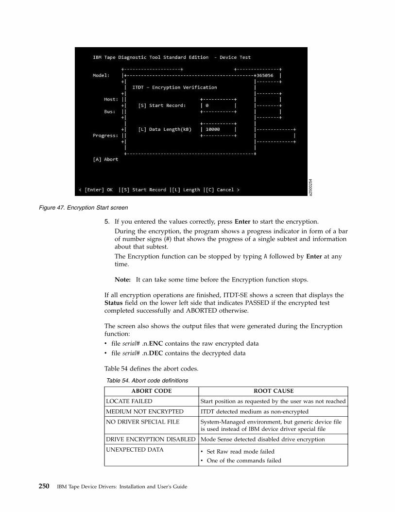
5. If you entered the values correctly, press Enter to start the encryption.During the encryption, the program shows a progress indicator in form of a barof number signs (#) that shows the progress of a single subtest and informationabout that subtest.The Encryption function can be stopped by typing A followed by Enter at anytime.
Note: It can take some time before the Encryption function stops.
If all encryption operations are finished, ITDT-SE shows a screen that displays theStatus field on the lower left side that indicates PASSED if the encrypted testcompleted successfully and ABORTED otherwise.
The screen also shows the output files that were generated during the Encryptionfunction:v file serial# .n.ENC contains the raw encrypted datav file serial# .n.DEC contains the decrypted data
Table 54 defines the abort codes.
Table 54. Abort code definitions
ABORT CODE ROOT CAUSE
LOCATE FAILED Start position as requested by the user was not reached
MEDIUM NOT ENCRYPTED ITDT detected medium as non-encrypted
NO DRIVER SPECIAL FILE System-Managed environment, but generic device fileis used instead of IBM device driver special file
DRIVE ENCRYPTION DISABLED Mode Sense detected disabled drive encryption
UNEXPECTED DATA v Set Raw read mode failed
v One of the commands failed
a2500254
Figure 47. Encryption Start screen
250 IBM Tape Device Drivers: Installation and User's Guide

Table 54. Abort code definitions (continued)
ABORT CODE ROOT CAUSE
END OF MEDIUM End of medium that is encountered before thespecified amount of data was read
END OF DATA End of data that is encountered before the specifiedamount of data was read
READ FAILED
ENCRYPTION ERROR
INVALID PARAMETER User entered data length of 0 kB
FILE IO ERROR The hard drive that ITDT is installed on might haverun out of space.
If you want to use other ITDT-SE functions, type R followed by Enter to return tothe device list. Otherwise, type Q followed by Enter to exit the program.
Configure TCP/IP
Configure TCP/IP [C] configures the ethernet port settings of LTO 5, LTO 6, LTO 7,TS1140, and TS1150 drives. For those drives, the current settings are read anddisplayed and can be changed.
Note: LTO 5, LTO 6, and LTO 7 drives have one port and TS1140 and TS1150drives have two ports that can be configured. Configuring the ethernet ports mustnot be done in a TS3500/TS4500. Although the ports can be configured, it isineffective.1. Start ITDT-SE, type S, and press Enter to scan for the devices.2. Select a device from the list (just the ones that are listed are supported) by
entering the number, then press Enter.3. Type O and press Enter to display the second device list screen.4. On the second device list screen, type C and press Enter to open the Configure
TCP/IP screen.
ITDT-SE switches to the Configure TCP/IP screen and reads the data configurationof port 1. To toggle between port 1 and 2, type P and press Enter.
Chapter 9. IBM Tape Diagnostic Tool (ITDT) 251
|
|
|
|

Each parameter can be set by entering the number (1 - 5) and a following value. Ifyou want to enable DHCP, enter '1 1' and press Enter. The value of the DHCPfield is refreshed with the value entered.
The values for both ports are applied to the drive by entering A and pressingEnter. ITDT-SE configures the drive and the current active addresses are shown inthe field: Active IP Addresses. Regular field values:[1] DHCP enabled: 0/1 (false/true)[2] Address IPV4 Regular IPv4 address[3] Subnet Mask Length V4: 0...23[4] Address IPV6: Regular IPv6 address[5] Subnet Mask Length V4: 0...127
If you want to use other ITDT-SE functions, type R, then press Enter to return tothe device list. Or, press Q and Enter to exit the program.
Return
Return [R] - type R followed by Enter to go back to the first device list screen.
Standard Edition - Tapeutil menu commands
When the user runs the U command on the ITDT-SE start screen, the Tapeutiloperation screen is displayed.
Note: On any screen, to start a command, press the shortkey displayed in brackets[ ], followed by Enter.
The following commands are described in this section:v “[1] Open a Device” on page 254v “[2] Close a Device” on page 255v “[3] Inquiry” on page 255v “[4] Test Unit Ready” on page 255
a2500281
Figure 48. TCP/IP screen: Read data
252 IBM Tape Device Drivers: Installation and User's Guide

v “[5] Reserve Device” on page 255v “[6] Release Device” on page 255v “[7] Request Sense” on page 255v “[8] Log Sense” on page 256v “[9] Mode Sense” on page 256v “[10] Query Driver Ver. (Version)” on page 256v “[11] Display All Paths” on page 256v “[12] Query Runtime Info” on page 256v “[20] Rewind” on page 256v “[21] Forward Space File Marks” on page 256v “[22] Backward Space File Marks” on page 256v “[23] Forward Space Records” on page 257v “[24] Backward Space Records” on page 257v “[25] Space to End of Data” on page 257v “[26] Read and Write Tests” on page 257v “[27] Read or Write Files” on page 257v “[28] Erase” on page 258v “[29] Load Tape” on page 258v “[30] Unload Tape” on page 258v “[31] Write File Marks” on page 258v “[32] Synchronize Buffers” on page 258v “[33] Query/Set Parameter” on page 258v “[34] Query/Set Tape Position” on page 258v “[35] Query Encryption Status” on page 259v “[36] Display Message” on page 259v “[37] Report Density Supp (Support)” on page 259v “[38] Test Encryp. Path (Test Encryption Key Path/Setup)” on page 259v “[39] Configure TCP/IP Port” on page 260v “[50] Element Information” on page 261v “[51] Position to Element” on page 261v “[52] Element Inventory” on page 261v “[53] Exchange Medium” on page 262v “[54] Move Medium” on page 262v “[55] Initialize Element Status” on page 262v “[56] Prevent/Allow Medium Removal” on page 262v “[57] Initialize Element Status Range” on page 262v “[58] Read Device IDs” on page 262v “[59] Read Cartridge Location” on page 262v “[70] Dump/Force Dump/Dump” on page 263v “[71] Firmware Update” on page 263v “[101] HDP Discover” on page 263v “[102] HDP Initiate Call Home” on page 264v “[103] HDP Show Import Export Elements” on page 264
Chapter 9. IBM Tape Diagnostic Tool (ITDT) 253

[1] Open a Device
When you select the Open a Device command [1]:1. ITDT checks if a device is already opened.2. You are prompted for a device special file name.3. You are prompted for an open mode (rw, ro, wo, append).4. ITDT opens the device that you selected.
Note: Always use the Read Only mode when you are working withwrite-protected media.
The combination of open cmd with parameter -force-generic-dd is not supported.
Device file names - device addressing
ITDT supports generic and Device Driver claimed devices. This section showsexamples for device names (addressing) of all supported platforms. The usedabbreviations stand for:
host Number of the host adapter (SCSI, FC, SAS)
bus Number of the bus from the host adapter
target Target Number of the device
lun Logical Unit Number of the device that is separated with blanks.
Note: The correct IDs are reported in the ITDT Control Center after a scan or withthe scripting function "scan".
Table 55. Device addressing
IBM TapeDevice Driver
Generic IDs separated withblanks
Generic (alternative, as aresult from ".itdt scan")
IBM AIX /dev/rmtX.Y
/dev/smcX
<host><bus><target><lun>H<host>-B<bus>-T<target>-L<lun>
Linux /dev/IBMtapeX
/dev/IBMchangerX
MicrosoftWindows
\\.\tape0
\\.\changer0
Oracle Solaris /dev/rmtXsmc
/dev/smc/Xchng
HP-UX /dev/rmt/Xmnb
/dev/rmt/Xchng
254 IBM Tape Device Drivers: Installation and User's Guide

Table 55. Device addressing (continued)
IBM TapeDevice Driver
Generic IDs separated withblanks
Generic (alternative, as aresult from ".itdt scan")
Apple Mac -
<host><bus><target><lun>
H<host>-B<bus>-T<target>-L<lun>
tapeX
changerX
IBM 'i' --
Device Name; forexample, TAP01
Example for Windows:C:\tmp\itdt.exe scanScanning SCSI Bus ...#0 \\.\Tape4 - [03592E06]-[2471] S/N:000012345678 H2-B0-T3-L0Exit with code:0C.\tmp
For a device that uses the IBM device driver, the call might look like \\.\Tape4,and for a generic device on Windows 2 0 3 0.
[2] Close a Device
When you select the Close a Device command [2]:1. ITDT checks if the device is already closed.2. ITDT closes the device.
[3] Inquiry
When you select the Inquiry command [3]:1. You are prompted for page code.2. ITDT then displays a decoded format of a hexadecimal dump and prints a
hexadecimal dump of the inquiry data.
[4] Test Unit Ready
When you select the Test Unit Ready (TUR) command [4], ITDT issues the TestUnit Ready ioctl command.
[5] Reserve Device
When you select the Reserve Device command [5], ITDT issues a reservecommand for the device.
[6] Release Device
When you select the Release Device command [6], ITDT issues a release commandfor the device.
[7] Request Sense
When you select the Request Sense command [7]:1. ITDT issues a Request Sense command.
Chapter 9. IBM Tape Diagnostic Tool (ITDT) 255

2. ITDT then displays a decoded format of hexadecimal dump sense data andprints hexadecimal dump sense data.
[8] Log Sense
When you select the Log Sense command [8]:1. You are prompted for Log Sense Page.2. ITDT issues a mode sense command.3. ITDT completes a hexadecimal dump page.
[9] Mode Sense
When you select the Mode Sense command [9]:1. You are prompted for Mode Sense Page.2. ITDT issues mode sense command.3. ITDT completes a hexadecimal dump page.
[10] Query Driver Ver. (Version)
When you select the Query Driver Version command [10]:1. ITDT issues the required command to get the driver version.2. ITDT prints the driver version.
[11] Display All Paths
When you select the Display All Paths command [11]:1. ITDT issues an ioctl command.2. ITDT outputs decoded path information for all paths.
[12] Query Runtime Info
When you select the Query Runtime Info command [12]:1. ITDT issues the required command to get the runtime info.2. ITDT prints out the Dynamic Runtime Attribute Values.
[20] Rewind
When you select the Rewind command [20], ITDT issues the ioctl rewind commandfor the device.
[21] Forward Space File Marks
When you select the Forward Space File Marks command [21]:1. You are prompted for the number of file marks to space forward.2. ITDT issues (extrinsic) ioctl command.
[22] Backward Space File Marks
When you select the Backward Space File Marks command [22]:1. You are prompted for the number of file marks.2. ITDT issues (extrinsic) ioctl command.
256 IBM Tape Device Drivers: Installation and User's Guide

[23] Forward Space Records
When you select the Forward Space Records command [23]:1. You are prompted for the number of records to space forward.2. ITDT issues (extrinsic) ioctl command.
[24] Backward Space Records
When you select the Backward Space Records command [24]:1. You are prompted for the number of records to space backward.2. ITDT issues (extrinsic) ioctl command.
[25] Space to End of Data
When you select the Space to End of Data (EOD) command [25], ITDT issues the(extrinsic) ioctl command.
[26] Read and Write Tests
When you select the Read and Write Tests command [26]:v You are prompted for block size (If you press Enter, the default block size is
10240 bytes).
Note: If the block size is zero, variable mode is used. With a fixed block size, adata amount of (block size * blocks) is transferred with a single operation. Thisprocess can get rejected if the total amount exceeds the transfer size the systemcan handle.
v You are prompted for the number of blocks per read/write (If you press Enter,the default number of blocks is 20).
v You are prompted for the number of repetitions (If you press Enter, the defaultnumber of repetitions is 1).
You can then select one of the following options:v Read data from tape (to run Read only test)v Write data to tape (to run Write-only test)v Write/Read/Verify (to run Read and Write test)
ITDT runs the selected test. Then, it displays the transfer size and block size that isused for this test, the number of records read/written, and the total bytestransferred.
[27] Read or Write Files
When you select the Read or Write Files command [27]:v You are prompted to specify the file name of the source file (for Write test) or
the destination file (for Read test).v You are prompted for the number of records to be read.
You can then select one of the following options:v Read File from Tape: ITDT reads a file from tape and stores data into a file with
the specified file name.v Write File to Tape: ITDT reads data from file with the specified file name and
writes data to tape.
Chapter 9. IBM Tape Diagnostic Tool (ITDT) 257

ITDT displays the number of records read/written, the transfer size, and the totalbytes transferred.
[28] Erase
When you select the Erase command [28], ITDT issues the (extrinsic) ioctlcommand to erase the cartridge.
For more information, refer to the Tapeutil Scripting Command at .
[29] Load Tape
When you select the Load Tape command [29], ITDT issues the load tapecommand.
[30] Unload Tape
When you select the Unload Tape command [30], ITDT issues the unload tapecommand.
[31] Write File Marks
When you select the Write File Marks command [31]:1. You are prompted for the number of file marks to write.2. ITDT issues the (extrinsic) ioctl command.
[32] Synchronize Buffers
When you select the Synchronize Buffers command [32], ITDT issues the ioctlcommand.
[33] Query/Set Parameter
When you select the Query/Set Parameter command [33]:1. ITDT displays non-changeable parameters.
Note: The list of non-changeable parameters is operating system specific.2. ITDT displays changeable parameters.
Note: The list of changeable parameters is operating system specific. For a listof changeable parameters, refer to .
3. You are prompted for parameter to change.4. ITDT requests prompt for parameter value (if required).5. ITDT requests safety prompt (if required).6. ITDT issues the ioctl command.
[34] Query/Set Tape Position
When you select the Query/Set Tape Position command [34]:1. ITDT displays the current position2. You are prompted for a new position to set.3. ITDT issues the Set Position ioctl command.
258 IBM Tape Device Drivers: Installation and User's Guide

[35] Query Encryption Status
When you select the Query Encryption Status command [35]:1. ITDT issues Get Encryption State ioctl command.2. ITDT displays encryption settings (Encryption capability, Encryption method,
Encryption state).
[36] Display Message
When you select the Display Message command [36]:1. You are prompted for the text of message 0 (8 characters or less).2. You are prompted for the text of message 1 (8 characters or less).3. You are prompted for message type (msg0, msg1, flash0, flash1, alt).4. ITDT issues the Display Message ioctl command.
Not all drives have a display. The 3592 drive is the only one that has displaymessage capability. It is the only one with a display that is more than one characterlong. Eight is the limit of the characters on a display screen.
[37] Report Density Supp (Support)
When you select the Report Density Support command [37]:1. ITDT prints report status text for all supported media.2. ITDT issues Report Density Support ioctl command to retrieve all supported
media.3. ITDT prints all requested reports. Data is printed in a decoded way. Scroll the
screen to print each one of the following information:v Density namev Assigning organizationv Descriptionv Primary density codev Secondary density codev Write OKv Duplicatev Defaultv Bits per MMv Media Widthv Tracksv Capacity (megabytes).
4. ITDT prints report status text for current media5. ITDT issues Report Density Support ioctl command to retrieve current media6. ITDT prints report data in a decoded way.
[38] Test Encryp. Path (Test Encryption Key Path/Setup)
When you select the Test Encryption Key Path/Setup command [38]:
Note: Not supported for the HP-UX operating system.1. ITDT prints status message that server configuration and connections are tested2. ITDT issues the Encryption Diagnostics ioctl command, Ping Diag
Chapter 9. IBM Tape Diagnostic Tool (ITDT) 259
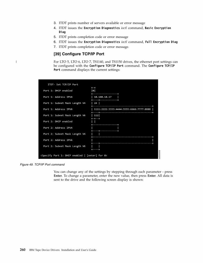
3. ITDT prints number of servers available or error message4. ITDT issues the Encryption Diagnostics ioctl command, Basic Encryption
Diag
5. ITDT prints completion code or error message6. ITDT issues the Encryption Diagnostics ioctl command, Full Encryption Diag7. ITDT prints completion code or error message.
[39] Configure TCP/IP Port
For LTO 5, LTO 6, LTO 7, TS1140, and TS1150 drives, the ethernet port settings canbe configured with the Configure TCP/IP Port command. The Configure TCP/IPPort command displays the current settings:
You can change any of the settings by stepping through each parameter - pressEnter. To change a parameter, enter the new value, then press Enter. All data issent to the drive and the following screen display is shown:
dd000009
Figure 49. TCP/IP Port command
260 IBM Tape Device Drivers: Installation and User's Guide
|

Note: Because earlier drive generations do not have an ethernet port, theConfigure TCP/IP Port command is rejected for these devices with the followingmessage:TCP/IP configuration is not supported on this product.
[50] Element Information
When you select the Element Information command [50]:1. ITDT issues the ioctl command2. ITDT displays thev Number of robotsv First robot addressv Number of slotsv First slot addressv Number of I/E elementsv First element addressv Number of drivesv First drive address
[51] Position to Element
When you select the Position to Element command [51]:1. You are prompted for destination address2. ITDT issues the ioctl command.
[52] Element Inventory
When you select the Element Inventory command [52]:1. ITDT issues the Element Info ioctl command.2. ITDT issues the Element Inventory ioctl command.
dd000010
Figure 50. TCP/IP Port command results
Chapter 9. IBM Tape Diagnostic Tool (ITDT) 261
3. ITDT displays decoded element inventory information. Type n followed byReturn to show the next page of information.
[53] Exchange Medium
When you select the Exchange Medium command [53]:1. You are prompted for source address.2. You are prompted for first destination address.3. You are prompted for second destination address.4. ITDT issues the ioctl command.
[54] Move Medium
When you select the Move Medium command [54]:1. You are prompted for source address.2. You are prompted for destination address.3. ITDT issues the ioctl command.
[55] Initialize Element Status
When you select the Initialize Element Status command [55]:1. ITDT prints the command summary.2. ITDT issues the ioctl command.
[56] Prevent/Allow Medium Removal
When you select the Prevent/Allow Medium Removal command [56]:1. You are prompted to select (1) for Prevent Removal, or (0) for Allow Removal.
[57] Initialize Element Status Range
When you select the Initialize Element Status Range command [57]:1. You are prompted for the first slot address.2. You are prompted for the number of slots.3. ITDT issues the ioctl command.
[58] Read Device IDs
When you select the Read Device IDs command [58], ITDT retrieves the device IDinformation for all available drives and displays the information. Type n followedby Enter to show the next page.
[59] Read Cartridge Location
When you select the Read Cartridge Location command [59]:1. You are prompted for the address of the first slot.2. You are prompted for number of elements.3. ITDT verifies that the specified address range is valid, otherwise prints error
message and exit.4. ITDT issues the Read Cartridge Location ioctl command.5. ITDT issues the Element Info ioctl command.6. ITDT verifies that the address range is valid; otherwise, print the error message
and exit.
262 IBM Tape Device Drivers: Installation and User's Guide

7. If no slots are found in Element Info data, print the error message and exit.8. ITDT issues the Read Cartridge Location ioctl command.9. ITDT prints decoded storage element information, Type n followed by Enter to
show next page.
[70] Dump/Force Dump/Dump
When you select the Dump/Force Dump/Dump command [70]:v ITDT retrieves the dump.v ITDT issues the Force Dump command.v ITDT retrieves second dump.v ITDT displays the name of stored dump files and the output directory where
they are stored. The dump file names start with the serial number of the device.
[71] Firmware Update
When you select the Firmware Update command [71]:1. ITDT displays the default input directory where the firmware files must be
stored. The following are examples of the directory:v Example input directory (Windows): c:\itdt\inputv Example input directory (UNIX): /home/user/itdt/input
2. You are prompted to specify a different input directory if required, or to pressEnter to keep the standard ITDT directory.
3. You are prompted to specify the firmware file name and press Enter to start.4. ITDT runs firmware update and displays progress status and result.
Note: See “3576/TS3310 tape library” on page 231 for information on how toupdate the firmware on a 3576/TS3310 tape library.The following site is available for the latest firmware files:http://www.ibm.com/storage/lto.
[101] HDP Discover
Discover the configuration of the HD-P system of all attached libraries - justTS3500/TS4500. The function scans the host for attached TS3500/TS4500 devicesand uses their data to discover the HD-P system.
If it is successful, it delivers two maps that represents the logical and physicalHD-P environment.
The logical map is a representation of the libraries, where a “1” is the indicator fora connection and a “-1” of no connection.Command Result
+-----------------------------------------------------------------------------+| Shuttle Call System discover..... || Scanning devices..... || .....DeviceFileName:/dev/smc1 SN:0000013AAA160404 || || Discovering Libraries...... || .....Passed || || Connection Map: || LL01: /dev/smc1 || || LL01 |
Chapter 9. IBM Tape Diagnostic Tool (ITDT) 263

| LL01 -1 || || Physical Map: || || || SCS Discover passed || || || |+-----------------------------------------------------------------------------+< [Q] Quit | [N] Next| [P] Previous | + | - | [Enter] Return >
Supported platforms: AIX, Linux on P, and X64
Note: Mixed Media environments (3592 and LTO) are not supported.
[102] HDP Initiate Call Home
Issuing a Test Call Home function.
Supported platforms: AIX, Linux on P, and X64
[103] HDP Show Import Export Elements
Shows the extended HD-P Import Export Elements.
Supported platforms: AIX, Linux on P, and X64
Standard Edition - Program options
For problem determination and customization, ITDT is providing the followingcommand line options.-h –help
Prints help information-version
Displays the version of ITDT,used configuration files and creation dates.
-force-generic-ddthe usage of the generic Operating System driver(not using the IBM Tape Device driver)will be forced.
-LP logpathUse ’logpath’ as logging path (default: output)
-L logfileUse ’logfile’ for log messages (default: metro.log)
-LL Errors|Warnings|Information|DebugSet log level (default: Error)
-R resultdirUse ’resultdir’ as result file path (default: output)
Standard Edition - Tapeutil scripting commands
Scripting is enabled with the 4.0 release of ITDT SE. ITDT-SE providescompatibility with earlier versions for existing tapeutil scripts. While some legacycommands exist, they are not documented in their entirety as they are phased outover time. New scripts must always use the scripts that are listed in this guide, theCommon Command set (CS). Also, existing scripts must be modified for forwardcompatibility with ITDT.
264 IBM Tape Device Drivers: Installation and User's Guide

You can find a list of commands, on each command you find the command, adescription, parameter list, and which platforms are supported. Some commandshave numbers after them. The numbers mean that a corresponding menucommand is in “Standard Edition - Tapeutil menu commands” on page 252.
The calling convention for the Common Command set isitdt -f filename [Open Mode] Subcommand [Subcommand ...]
Note: "filename" is a device special file for the drive/changer or the deviceaddress (host bus target lun). For a complete list of the file name or addresssyntax, refer the section "Special Files" on each platform or go to “Device filenames - device addressing” on page 254.
The Open Mode flag is supported on all platforms. If the flag is not set, the deviceis opened in read/write mode. More parameters that might be required foropening the device are automatically detected and set.-w mode
Open mode, by default Read/Write.Valid modes are:1 = Read/Write2 = Read Only3 = Write Only4 = Append
Note: Always use the Read Only mode when you are working withwrite-protected media.
The new command set enables legacy commands on every platform, even if that isnot previously supported by Tapeutil. The output follows current Tapeutilconventions. But, if different output displays for a single command on variousplatforms, the output is implemented according to the AIX output as the primaryscripting platform.
Tapeutil allows undocumented abbreviations for some of the commands. Forexample, it was possible to shorten “inquiry” to “inq” or “inqu” or “inqui”. Thefollowing command abbreviations are supported by ITDT-SE too: inq(uiry),req(sense), pos(ition), ele(mentinfo), inv(entory), devid(s), cartridge(location).Deprecated commands are listed at “Deprecated commands” on page 289. Also,there is a list of unsupported commands and known exceptions at “StandardEdition scripting commands: known limitations and deviations” on page 291.
The following commands are described.
General commandsv “allow” on page 267v “devinfo” on page 267v “inquiry” on page 268v “logpage” on page 268v “loop” on page 268v “modepage” on page 268v “prevent” on page 268v “print” on page 269v “qrypath” on page 269v “qryversion” on page 269
Chapter 9. IBM Tape Diagnostic Tool (ITDT) 265

v “release” on page 269v “reqsense” on page 269v “reserve” on page 270v “scan” on page 270v “sleep” on page 271v “tur” on page 271v “vpd” on page 271
Tape commandsv “append” on page 271v “bsf” on page 272v “bsr” on page 272v “chgpart” on page 272v “density” on page 272v “display” on page 272v “erase” on page 273v “fdp” on page 273v “fdpl” on page 273v “fsf” on page 274v “fsr” on page 274v “getparms” on page 274v “idp” on page 274v “idpl” on page 275v “list” on page 275v “load” on page 275v “logsense” on page 276v “qrypar/qrypart” on page 276v “qrylbp” on page 276v “qrypos” on page 276v “qrytcpip” on page 276v “read” on page 277v “resetdrive” on page 277v “rmp” on page 277v “runtimeinfo/qryruntimeinfo” on page 277v “rewind” on page 277v “rtest” on page 278v “rwtest” on page 278v “sdp [0|1|2|3]” on page 278v “sdpl [0|1]” on page 278v “seod” on page 279v “setparm” on page 279v “setpos” on page 280v “settcpip” on page 280v “sync” on page 281v “unload” on page 281
266 IBM Tape Device Drivers: Installation and User's Guide

v “verlbp” on page 281v “weof” on page 282v “write” on page 282v “wtest” on page 282
Medium Changer Subcommandsv “audit” on page 282v “cartridgelocation” on page 283v “elementinfo” on page 283v “exchange” on page 283v “inventory” on page 283v “move” on page 284v “position” on page 284
Service Aid commandsv “dump” on page 284v “ekmtest” on page 284v “encryption” on page 284v “ucode” on page 284v “tapephcp” on page 285v “ltfsphcp” on page 285v “verify” on page 286v “checkltfsreadiness” on page 286v “ltfsdefragmentation” on page 286v “standardtest” on page 287v “fullwrite” on page 287v “systemtest” on page 288v “tapeusage” on page 288
HD-P commandsv “hdp discover” on page 288v “hdp senderror” on page 288v “hdp show” on page 289
allow
(Deprecated: unlock, -o rem) Allow medium removal for tape or changer devices(unlock door). The counter command for this is prevent.
Parameters:None
Supported platforms: All
devinfo
(Deprecated: -o gdi) Show device information (device type, sub type and blocksize)
Parameters:
Chapter 9. IBM Tape Diagnostic Tool (ITDT) 267

None
Supported platforms: AIX, Solaris, HP-UX
inquiry
(Deprecated: -o inq) Issue an Inquiry command and dump the bytes in Hex.
Parameters:inquiry [Page code in Hex, 00-FF without leading x]
Note: ITDT prints a hex dump of the inquiry data on all platforms.
Supported platforms: All
logpage
(Deprecated: -o log) This subcommand issues the SCSI Log Sense command to thedevice for the specified page and displays the log sense data.
Parameters:Page (page in hex without the leading x)[Subpage] (in hex without leading x)
Supported platforms: All
loop
This subcommand loops all subsequent subcommands continuously or a numberof times if the Count parameter is specified. Also refer to the sleep subcommand.
Parameters:loop [Count]
Supported platforms: All
modepage
(Deprecated: -o mod) This subcommand issues the SCSI Mode Sense command tothe device for the specified page and displays the mode sense data.
Parameters:modepage Page (page in hex without leading x)
Supported platforms: All
prevent
(Deprecated: -o lck, lock) Prevent medium removal for tape or changer devices(lock door). The counter command for this command is allow.
Parameters:None
Supported platforms: All
268 IBM Tape Device Drivers: Installation and User's Guide

This subcommand prints the associated text to standard output. It can be used atany time to display the progress of the subcommands.
Parameters:print Text
Supported platforms: All
qrypath
(Deprecated: -o phs, path, checkpath) This subcommand displays informationabout the device and SCSI paths, such as logical parent, SCSI IDs, and the status ofthe SCSI paths for the primary path and all alternate paths that are configured.
Parameters:None
Note: ITDT shows the entire path information for all the commands.
Supported platforms: All
qryversion
(Deprecated: -o drv) This subcommand prints out the current version of the IBMdevice driver.
Parameters:None
Supported platforms: All
release
(Deprecated: -o rel) This subcommand explicitly releases a device and makes itavailable for other hosts by issuing the SCSI Release command.
Parameters:None
Supported platforms: All
reqsense
(Deprecated: -o req) This subcommand issues the SCSI Request Sense command tothe device and displays the sense data in hex format.
Parameters:None
Supported platforms: All
Chapter 9. IBM Tape Diagnostic Tool (ITDT) 269

reserve
(Deprecated: -o res) This subcommand explicitly reserves a device by issuing theSCSI Reserve command.
Parameters:None
Supported platforms: All
scan
Displays the list of connected devices. For each detected device special file name,vendor id, firmware version, serial-number, SCSI bus address, associated changer,and device driver name is shown.
Parameters:[-force-generic-dd] [-o formatstring]
Supported platforms: All
Example scan:./itdt scanScanning SCSI Bus ...#0 /dev/IBMtape3 - [ULT3580-TD5]-[ACDF] S/N:1168001104 H3-B0-T3-L0#1 /dev/IBMchanger1 - [3573-TL]-[9.20] S/N:00L4U78D6118_LL0 H3-B0-T5-L1#2 /dev/IBMtape7 - [ULTRIUM-TD4]-[A232] S/N:1310000593 H1-B0-T0-L0
By using the optional parameter -force-generic-dd, the usage of the genericOperating System driver (not with the IBM Tape Device Driver) is forced.
The formatstring controls the output and specifies how the connected devices mustbe reported. It can include any alphanumeric character. The default formatstring is“"#%# %D - [%P]-[%F] S/N:%S H%H-B%B-T%T-L%L".
Interpreted identifiers are%D device name%V vendor name%P product name%F firmware version%S serial number%H host adapter%B bus number%T target id%L logical unit%h host adapter as hexadecimal value%b bus number as hexadecimal value%t target id as hexadecimal value%l logical unit as hexadecimal value%I interface type%# enumeration number%C serial number of associated changer device
Minimum field width:
An integer that is placed between a % sign and the format command acts as aminimum field width specifier, a negative value uses right text alignment.
Example scan with format string:
270 IBM Tape Device Drivers: Installation and User's Guide

./itdt scan -o "%-2#. %-18S %-12P %F %I"Scanning SCSI Bus ...0. 1310115166 ULT3580-TD4 97F2 Fibre1. 1310034311 ULT3580-TD4 A232 Fibre2. 1168001104 ULT3580-TD5 B170 Fibre3. 00L4U78D6118_LL0 3573-TL 9.20 N/A4. 00L2U78G8705_LL0 3573-TL 9.20 N/A5. 000001327208 03592E06 26CA Fibre6. cigen22164 ULT3580-TD2 73V1 Fibre7. 000001365271 03592E05 1DD1 Fibre
Exit with code: 0
Any combination of the identifiers that are listed here are supported.
Known problem: On Solaris for IBM device driver managed device: theinformation about the host, bus, target, and lun for generic devices is incorrect.
sleep
Sleep for the specified number of seconds before running the next subcommand.
Parameters:sleep [Seconds]
Supported platforms: All
tur
(Deprecated: -o tur) This subcommand issues the SCSI Test Unit Ready commandto the device.
Parameters:None
Supported platforms: All
vpd
This subcommand displays Vital Product Data (VPD) that are part of the Inquirycommand data and outputs Manufacturer, Product Identification and RevisionLevel.
Parameters:None
Supported platforms: All
append
Opens the device in append mode. The file access permission is Write Only.
Parameters:None
Chapter 9. IBM Tape Diagnostic Tool (ITDT) 271

Supported platforms: All, but on Windows this open mode is not supported by theIBM Tape Device Driver. On HP-UX this open mode is remapped to r/w by theIBM Tape Device Driver.
bsf
(Deprecated: -o bsf) This subcommand backward spaces Count filemarks. Thetape is positioned on the beginning of the last block of the previous file. Anoptional Count can be specified. The default is 1.
Parameters:bsf [Count]
Supported platforms: All
bsr
(Deprecated: -o bsr) This subcommand backward spaces Count records. Anoptional count can be specified. The default is 1.
Parameters:bsr [Count]
Supported platforms: All
chgpart
This subcommand changes the current active tape partition to a new partitionspecified by Number. Optionally, a Blockid can also be specified. If Blockid isomitted, the tape is positioned at the start of the new partition. Otherwise, the tapeis positioned at the Blockid specified.
Parameters:Number [Blockid]
Supported platforms: All
density
(Deprecated: -o gdn / -o rds) This subcommand issues the SCSI Report DensitySupport command for all supported media and for the current media loaded in thedrive, and displays the results. If the drive is not loaded, the current media densityis not reported.
Parameters:None
Note: ITDT-SE outputs detailed information on all platforms.
Supported platforms: All
display
(Deprecated: -o msg) This subcommand displays a message on the display panel ofthe tape device. Up to 16 characters can be used for the message. If the message islonger than eight characters, the display alternates between the first eightcharacters and the remainder of the message.
272 IBM Tape Device Drivers: Installation and User's Guide

Parameters:display “message1” “message2”
Supported platforms: All
erase
(Deprecated: -o era) This subcommand writes EOD at the current position anderases the tape from EOD to the end of current partition.
Parameters:None
Supported platforms: All except i5/OS operating system
Note: The erase command triggers a long erase of the cartridge that sets EOD tothe current position. Then, it writes the Data Set Separator (DSS) pattern from thenew EOD to the end of the current partition. This process overwrites any data thatis on the cartridge after the current logical position. To remove the entire cartridge,the user must remove all partitions (use the rmp command for LTO 5, TS1140, andnewer drives). Then, issue the rewind command before the erase command.
Examples:
For LTO 5 / TS1140 and lateritdt -f <device name> load rmp rewind erase
For all earlier LTO and Enterprise drive generationsitdt -f <device name> load rewind erase
fdp
This subcommand creates fdp (fixed data partitions) wrap wise. The default sizefor LTO 5 of partition 0 in this case is 1425 GB and the size of partition 1 is 37.5GB. It also works for Jaguar 4 but the size depends on the used cartridge.Supported by LTO 5, Jaguar 4, and later.
Parameters:None
Supported platforms: All
fdpl
This subcommand creates fdp (fixed data partitions) longitudinal. The command isvalid only for Jaguar drives (Jaguar 4 and later) and creates partitions 0 and 1 onthe cartridge. The size depends on the used cartridge.
Parameters:None
Supported platforms: All
Chapter 9. IBM Tape Diagnostic Tool (ITDT) 273

fsf
(Deprecated: -o fsf) This subcommand forward spaces count filemarks. The tapeis positioned on the first block of the next file. An optional count can be specified.The default is 1.
Parameters:fsf [Count]
Supported platforms: All
fsr
(Deprecated: -o fsr) This subcommand forward spaces count records. An optionalcount can be specified. The default is 1.
Parameters:fsr [Count]
Supported platforms: All
getparms
(Deprecated: -o parms / status / -o gpa) Get and show drive, media and driverparameters.
Parameters:None
Supported platforms: All
idp
This subcommand creates initiator defined partitions (IDP) wrap wise on tape. Theparameter pSize0 is used to specify the size of partition 0 and the parameter pSize1is used to specify the size of partition 1. One of pSize0 or pSize1 must have avalue that is entered in hex matching 37.5 * n with (1 <= n <= 38) to specify thewanted size of that partition. The other parameter of pSize0 or pSize1 must havethe value 0xFFFF to specify that the remaining capacity is used for that partition. If0xFFFF is not used for one of the parameters, pSize0 or pSize1, the drive mightreject the command | unless pSize0 and pSize1 exactly match predefined allowablevalues.
For Jaguar 4 (not for LTO 5) the parameters pSize2 and pSize3 are valid and theyfollow the same rules as described earlier.
For example: If you want a 37.5 GB partition (the minimum size partition) inpartition 0 and the remainder in partition 1, then set pSize 0 to 0x26 and pSize1 to0xFFFF. This action results in a volume with a 37.5 GB sized partition 0 and a 1425GB sized partition 1.
Parameters:idp pSize0 pSize1pSize0: size of partition 0pSize1: size of partition 1
274 IBM Tape Device Drivers: Installation and User's Guide
Example Call:idp 0x26 0xffff
Supported platforms: All
idpl
This subcommand creates initiator defined partitions (IDP) longitudinal wise ontape. The parameter pSize0 is used to specify the size of partition 0 and theparameter pSize1 is used to specify the size of partition 1. One of pSize0 or pSize1must have a value that is entered in hex matching 37.5 * n with (1 <= n <= 38) tospecify the wanted size of that partition. The other parameter of pSize0 or pSize1must have the value 0xFFFF to specify that the remaining capacity is used for thatpartition. If 0xFFFF is not used for one of the parameters, pSize0 or pSize1, thedrive might reject the command | unless pSize0 and pSize1 exactly matchpredefined allowable values.
For Jaguar 4 (not for LTO 5) the parameters pSize2 and pSize3 are valid and theyfollow the same rules as described earlier.
For example: If you want a 37.5 GB partition (the minimum size partition) inpartition 0 and the remainder in partition 1, then set pSize 0 to 0x26 and pSize1 to0xFFFF. This action results in a volume with a 37.5 GB sized partition 0 and a 1425GB sized partition 1.
Parameters:idp pSize0 pSize1pSize0: size of partition 0pSize1: size of partition 1
Example Call:idp 0x26 0xffff
Supported platforms: All
list
This subcommand displays the content of a tape. The output lists filemarks andthe size of each record found on the tape until the end of data is reached. Theoutput that is generated from this subcommand can be large depending on theamount of data on the tape and must usually be redirected to a file.
Parameters:None
Supported platforms: All
load
(Deprecated: -o lod) This subcommand issues a SCSI Load command to load atape. The subcommand loops all subsequent subcommands continuously or anumber of times if the Count parameter is specified. Also refer to the sleepsubcommand.
Parameters:None
Chapter 9. IBM Tape Diagnostic Tool (ITDT) 275

Supported platforms: All
logsense
Retrieves all Log Sense pages and outputs them as hex.
Parameters:None
Supported platforms: All
qrypar/qrypart
Queries and displays tape partitioning information.
Parameters:None
Supported platforms: All
qrylbp
Queries and displays logical block protection information.
Parameters:None
Supported platforms: All
qrypos
(Deprecated: -o gpo) This subcommand displays the current tape position.
Parameters:None
Supported platforms: All
qrytcpip
This subcommand outputs the current drive TCP/IP configuration. Only supportedwith LTO 5, LTO 6, LTO 7, TS1140, and TS1150. Outputs adapter and TCP/IPaddress information for IPv4 and IPv6 with address, port and subnet mask. Forexample:./itdt -f /dev/IBMtape3 qrytcpipReading current TCP/TP Configuration...Number of Port Descriptors 1Port Descriptor for Port 1Number of Socket Descriptors 2Adapter:1 IPV4 9.11.22.111/23 DHCP:0Adapter:2 IPV6[0002:0000:0000:0000:0007:0008:0000:0000]/24Active IP Addresses:IPv4: 169.254.0.3Exit with code: 0
Parameters:None
276 IBM Tape Device Drivers: Installation and User's Guide
|
Supported platforms: All
read
This subcommand reads a file, or a specified number of records, from the tape tothe destination file name specified with the -d flag. If the optional count parameteris used, only the number of records that are specified with the -c flag are readunless a filemark is encountered before the number of specified records. If thecount parameter is not used, all records up to the next filemark on tape are read.
Parameters:read -d Dest [-c Count]
Supported platforms: All
resetdrive
This subcommand issues a Send Diagnostic command (Reset Drive subcommand)to reset the device.
Parameters:None
Supported platforms: All
rmp
Remove partitioning.
Parameters:None
Supported platforms: All
runtimeinfo/qryruntimeinfo
This subcommand is used to query the dynamic runtime information. Dynamicruntime information allows an initiator to set dynamic runtime attributes (DRA)about itself into a device server. The device server then associates those attributesto the I_T_L nexus and uses the information and associations for enhanced datacollection and debugging.
Parameters:None
Supported platforms: All (supported since LTO 5 and 3592 E07)
rewind
(Deprecated: -o rew) Rewinds the tape.
Parameters:None
Supported platforms: All
Chapter 9. IBM Tape Diagnostic Tool (ITDT) 277

rtest
(Deprecated: -o rea) This subcommand runs a read test by reading a random datapattern from the tape and verifying that it matches the written data. The rtestsubcommand can be used after the wtest subcommand to verify the data. Anoptional block size, count, and repetition can be specified with the -b, -c, and -rflags, respectively. If the block size is fixed, then the count specifies the number ofblocks to read on each repetition. If the block size is zero (variable), then the countspecifies the number of bytes to read on each repetition. The default is a block sizeof 10240, a count of 20 blocks, and a repetition of 1.
Parameters:read [-b Blocksize] [-c Count] [-r Repetition]
Supported platforms: All
rwtest
This subcommand runs a read and write test by writing a random data pattern onthe tape, reading it, and verifying that it matches the written data. An optionalblock size, count, and repetition can be specified with the -b, -c, and -r flags,respectively. If the block size is fixed, then the count specifies the number of blocksto write on each repetition. A single transfer transmits (block size * count) bytes.The operation is rejected if the total amount exceeds the transfer size the system iscapable of. If the block size is zero (variable), then the count specifies the numberof bytes to write on each repetition. The default is a block size of 10240 bytes, acount of 20 blocks, and a repetition of 1.
Parameters:rwtest [-b Blocksize] [-c Count] [-r Repetition]
Supported platforms: All
sdp [0|1|2|3]
Creates SDP (Select Data Partitions) wrap wise on tape.
Parameters:Type numberFor LTO (5 and higher) only the values 0 and 1 are valid.Using value 0 as parameter leads to partition 0 with 1.5TBand partition 1 does not exist.
Using value 1 as parameter leads to partition 0 with 750 GBand partition 1 with 712.5 GB.
For Jaguar (4 and higher) values 0, 1, 2 and 3 are valid.Using value 0 as parameter will create only one partition,value 1 creates two and so on.
The sizes of the partitions are depending on the cartridge used in drive.
Supported platforms: All
sdpl [0|1]
Creates SDP (Select Data Partitions) longitudinal on tape.
Parameters:
278 IBM Tape Device Drivers: Installation and User's Guide

Type numberFor Jaguar (4 and higher) values 0 and 1 are valid.Using the value 0 as the parameter creates partition 0 onlyand the value 1 as the parameter creates partitions 0 and 1.
The sizes of the partitions depends on the cartridgeused in drive.
Supported platforms: All
seod
(Deprecated: -o eod) Spaces to end of data on the tape.
Parameters:None
Supported platforms: All
setparm
(Deprecated: -o spa / volid / compress / nocompress / sili / nosili /autoload / noautoload / retain / noretain)
ITDT-SE uses the new setparm option that corresponds to the current interactivemode options.
Parameters: The Value isv 0-65535 for the blocksize parameterv 0-100 for the capacity parameter (=percentage)v 1 (SCSI) and 2 (AIX) for recordspacemodev The Volume Id string for the volid parameterv NONE|ASSO|PERS|WORM for the writeprotect parameterv 0 for off/no and 1 for on/yes for setparm autoload, autodump, buffering,
compression, immediate, readpastfilemark, sili, simmim, trace, trailer,volumelogging
Supported platforms: All, but only a subset of the parameters is supported by theplatform's device drivers.
Table 56. Supported platforms
Linux Windows AIX Solaris HP-UX
setparm autoload X
setparm autodump X
setparm blocksize X X X X X
setparm buffering X X X X
setparm capacity X X3 X X X
setparm compression X X X X X
setparm datasafemode¹ X X X X X
setparm immediate X X X X
setparm readpastfilemark X
setparm recordspacemode X
setparm sili X X X
Chapter 9. IBM Tape Diagnostic Tool (ITDT) 279

Table 56. Supported platforms (continued)
Linux Windows AIX Solaris HP-UX
setparm simmim X
setparm skipsync² X X X X X
setparm sleepmode X X X X X
setparm trace X
setparm trailer X X X X
setparm volid X
setparm volumelogging X X
setparm writeprotect² X X3 X X X
Note:
1. The datasafemode can be set to YES or NO when no cartridge is loaded. Whena cartridge is loaded, the datasafemode can be set only to YES.
2. Depending on the support of the device.3. Only supported by 3592.
setpos
(Deprecated: -o spo / asf) This subcommand issues the SCSI Locate command tothe device to set the tape position. If the optional Blockid parameter is specified,the tape position is set to the Blockid. Otherwise, if the Blockid parameter isomitted, the tape position is set to the last position saved by using the qrypossubcommand.
Parameters:setpos [Blockid]
Supported platforms: All
settcpip
This subcommand sets the drive ethernet port TCP/IP settings for LTO 5, LTO 6,LTO 7, TS1140, and TS1150 drives. Either a static IPv4 or IPv6 address can be set orDHCP enabled.
Example DHCP:./itdt -f /dev/IBMtape3 settcpip DHCPInitializing device...Setting TCP/TP Configuration...Reading current TCP/TP Configuration...Number of Port Descriptors 1Port Descriptor for Port 1Number of Socket Descriptors 2Adapter:1 IPV4 9.11.22.111/23 DHCP:1Adapter:2 IPV6 [0002:0000:0000:0000:0007:0008:0000:0000]/24Active IP Addresses:Exit with code: 0
IPv4 or IPv6 addresses are entered in the syntax a.b.c.d:/subnet_mask_lengthwhere a, b, c, and d are values with 1 to 3 digits. If the optional parametersubnet_mask_length is not specified, the current setting is kept.
280 IBM Tape Device Drivers: Installation and User's Guide
||

Example static IPv4:./itdt -f /dev/IBMtape3 settcpip 9.155.27.14/23Initializing device...Setting TCP/TP Configuration...Reading current TCP/TP Configuration...Number of Port Descriptors 1Port Descriptor for Port 1Number of Socket Descriptors 2Adapter:1 IPV4 9.155.27.14/23 DHCP:0Adapter:2 IPV6 [0002:0000:0000:0000:0007:0008:0000:0000]/24
Active IP Addresses: IPv4:
169.254.0.3 IPv4:
9.155.27.46 IPv4:
9.155.27.14
Exit with code: 0
Parameters:dhcp, address[/subnet_mask_length]
Supported platforms: All
Note: With the current firmware level, the device can be reached (ping, FTP) onlywithin the same subnet. For example, the sample is configured with a static IPaddress (9.155.27.14) and DHCP enabled. The drive can be pinged only within thesame subnet (9.155.27.xxx). Both IP addresses (9.155.27.14 and the DCP address9.155.27.46) are active and can be used.
sync
(Deprecated: -o syn) This subcommand synchronizes buffers/flushes the tapebuffers to tape.
Parameters:None
Supported platforms: All
unload
(Deprecated: -o off / offline / rewoffl) This subcommand rewinds and unloadsthe tape.
Parameters:None
Supported platforms: All
verlbp
This subcommand verifies logical block protection written blocks. The verificationlength can be set with parameter value filemarks count or with EOD.
Parameters:
Chapter 9. IBM Tape Diagnostic Tool (ITDT) 281

filemarks (numeric value) | eod
Supported platforms: All
weof
(Deprecated: -o eof / eof) These subcommands write count filemarks. Anoptional count can be specified. The default is 1.
Parameters:weof [Count]
Note: The weof parameter [count] is optional, if it is not supplied, one filemark iswritten.
Supported platforms: All
write
This subcommand writes the source file specified with the -s flag on the tape. Incase the parameter 'raw' is specified, the blocksize specified in setparm (setparmblocksize) is used instead of the default blocksize of 64 kB.
Parameters:[-raw] -s Source
Supported platforms: All
wtest
(Deprecated: -o wri) This subcommand runs a write test by writing a random datapattern on the tape. The rtest subcommand can be used after the wtestsubcommand to verify the data that was written. An optional block size, count,and repetition can be specified with the -b, -c, and -r flags, respectively. If theblock size is fixed, the count specifies the number of blocks to write on eachrepetition. If the block size is zero (variable), the count specifies the number ofbytes to write on each repetition. The default is a block size of 10240, a count of 20blocks, and a repetition of 1.
Parameters:wtest [-b Blocksize] [-c Count] [-r Repetition]
Supported platforms: All
audit
(Deprecated: -o aud / -o ier) This subcommand with no parameters issues theSCSI Initialize Element Status command to the device. Using the optionalparameters Address and Count issues the SCSI Initialize Element Status WithRange command to the device. The Address parameter specifies the startingelement address and the Count parameter, if used, specifies the number ofelements to initialize. If Count is omitted, it defaults to 1.
Parameters:audit [[Address] [Count]]
282 IBM Tape Device Drivers: Installation and User's Guide

Supported platforms: All
cartridgelocation
This subcommand with no parameters issues the SCSI Read Element Statuscommand to the device to report all slots with the cartridge location information.Using the optional parameters Slot and Count issues the SCSI Read Element Statusto the device for a specific starting Slot address and optionally the Count specifiesthe number of slots to return. If Count is omitted, it defaults to 1.
Parameters:cartridgelocation [Slot [Count]]
Supported platforms: All
elementinfo
(Deprecated: -o ele) This subcommand displays element information (number andaddress) of each element type.
Parameters:None
Supported platforms: All
exchange
(Deprecated: -o exh) This subcommand issues the SCSI Exchange Mediumcommand to the device by using the Source, Dest1, and Dest2 addresses specified.This command runs the equivalent function of two Move Medium commands. Thefirst moves the cartridge from the element address that is specified by the Dest1parameter to the element address specified by the Dest2 parameter. The secondmoves the cartridge from the element address that is specified by the Sourceparameter to the element address specified by the Dest1 parameter.
Parameters:exchange Source Dest1 Dest2
Supported platforms: All
inventory
(Deprecated: -o inv) This subcommand with no parameters issues the SCSI ReadElement Status command for each element type and displays the element statusinformation. If the optional -i parameter is used, then only the import/exportelement status information is returned. If the optional -v parameter is used, thenonly the element status information for the specified Volid if found is returned.
Parameters:inventory [-i | -v Volid]
Note: ITDT supports the optional parameters on all platforms.
Supported platforms: All
Chapter 9. IBM Tape Diagnostic Tool (ITDT) 283

move
(Deprecated: -o mov) This subcommand issues the SCSI Move Medium commandby using the source and destination addresses specified. The element addresses canbe obtained with the elementinfo subcommand.
Parameters:move Source Dest
Supported platforms: All
position
(Deprecated: -o pos) This subcommand issues the SCSI Position to Elementcommand by using the destination specified.
Parameters:position Dest
Supported platforms: All
dump
(Deprecated: -o sdp) This subcommand forces a dump of the tape drive and storesthe dumps before and after the force dump in the ITDT-SE output folder with theITDT-SE naming convention (serialnumber.a.gz and serialnumber.b.gz).
Parameters:None
Supported platforms: All
ekmtest
Test encryption key path/setup.
Parameters:None
Supported platforms: AIX, Linux, Solaris, Windows
encryption
Query tape drive encryption settings and display the encryption state.
Parameters:None
Supported platforms: All
ucode
(Deprecated: -o dmc) This subcommand downloads microcode to the device. TheFilename is a file that contains the ucode.
Parameters:
284 IBM Tape Device Drivers: Installation and User's Guide

ucode Filename
Supported platforms: All
tapephcp
Creates a physical copy of a tape cartridge. The created cartridge has the samephysical layout and contents as the origin cartridge. The amount of transferreddata and the current data transfer rate is displayed every 3-5 minutes. Tapephcp issupported for LTO and 3592 tape drives and can therefore be used for datamigration. A tapephcp command that is issued to copy data from a 3592 drive toan LTO drive or from an LTO Gen 4 to an LTO Gen 3 works, if the amount of useddata from the source device is equal or less than the capacity of the destinationdevice.
Parameters:tapephcp [-cqs Memorysize] source destination
Source and destination can either a special device file name, or a tape image filename. The special device file format is identical to the format specified in chapter3.19 parameter “-f device”.
Examples: Tape to Tape copy with the IBM tape driver./itdt tapephcp /dev/IBMtape0 /dev/IBMtape1Tape to Image File using generic interface./itdt tapephcp 3 2 1 0 /tmp/MyTapeImage.img
Image File to Tape using IBM Tape driver./itdt tapephcp /tmp/MyTapeImage.img /dev/IBMtape1
Tape to Tape copy with adjusted memory allocation./itdt tapephcp -cqs 1000 /dev/IBMtape0 /dev/IBMtape1
To ensure maximum performance for tape to tape copy actions, tapephcp allocatesa read buffer of 2500 MB (assuming the maximum system block size is 1 MB). Ifthe system does not provide this buffer, the operation is aborted with MEMORYALLOCATION FAILED. The value for memory allocation can be changed with aninteger value for the parameter cqs (Command Queue Size). The cqs value mustbe multiplied with the maximum supported system blocksize to determine the sizeof memory that is allocated by ITDT. Supported copy operations are from tape totape, from image file to tape, and from tape to image file.
ltfsphcp
Creates a physical copy of an LTFS formatted cartridge. Ltfsphcp is based ontapephcp. The LTFS specified parameters volumeuuid and VCI are adjusted duringthis copy operation. The created cartridge has the same physical layout as theorigin cartridge. Expect the volumeuuid to be identical to the contents of the twocartridges. The amount of transferred data and the current data transfer rate isdisplayed every 3-5 minutes. When ltfsphcp is used with a non-LTFS formattedcartridge, the behavior of ltfsphcp is identical to tapephcp.
Parameters:ltfsphcp [-cqs Memorysize] source destination
Source and destination can either a special device file name, or a tape image filename. The special device file format is identical to the format specified in chapter3.19 parameter “-f device”.
Chapter 9. IBM Tape Diagnostic Tool (ITDT) 285
|
||
|||||||
|

Examples:Tape to Tape copy using IBM tape driver./itdt ltfsphcp /dev/IBMtape0 /dev/IBMtape1
Tape to Image File using generic interface./itdt ltfsphcp 3 2 1 0 /tmp/MyTapeImage.img
Image File to Tape using IBM Tape driver./itdt ltfsphcp /tmp/MyTapeImage.img /dev/IBMtape1
Tape to Tape copy with adjusted memory allocation./itdt ltfsphcp -cqs 1000 /dev/IBMtape0 /dev/IBMtape1
To ensure maximum performance for tape to tape copy actions, ltfsphcp allocates aread buffer of 2500 MB (assuming the maximum system block size is 1 MB). If thesystem does not provide this buffer, the operation is aborted with MEMORYALLOCATION FAILED. The value for memory allocation can be changed with aninteger value for the parameter cqs (Command Queue Size). The cqs value mustbe multiplied with the maximum supported system blocksize to determine the sizeof memory that is allocated by ITDT. Supported copy operations are from tape totape, from image file to tape, and from tape to image file.
verify
Verifies the physical contents of two cartridges. The physical data layout and thebinary data are compared.
Parameters:source destination
Source and destination can either a special device file name, or a tape image filename. The special device file format is identical to the format specified in chapter3.19 parameter -f.
Examples:./itdt verify /dev/IBMtape0 /dev/IBMtape1
checkltfsreadiness
This subcommand issues the LTFS Readiness Check test.
The LTFS Readiness Check analyzes the Operating System and tape driveenvironment to ensure that the IBM Linear Tape file system can be installed. Thistest checks the Operating System version, the tape device driver version, the tapedrive firmware, and the LTFS HBA requirements. LTFS Readiness Check requiresan empty data cartridge.
ltfsdefragmentation
On an LTFS formatted cartridge, the physical data records for a single file can befragmented across the entire media. When such a file is accessed, a long responsetime might result. The tape drive must locate to different cartridge positions toretrieve the entire contents the file. If the first data records of a file are stored atthe end of the tape and the other records are stored at the beginning of the media,the tape drive must run several times intensive seek operations to fulfill thecomplete file retrieval. This subcommand creates a copy of the cartridge withunfragmented content.
As an initial step, ITDT stores the complete content of the source tape media in aTape Image file that is on an HDD. Using this Tape Image file and the ITDT image
286 IBM Tape Device Drivers: Installation and User's Guide
||
|||||||

file backend driver for LTFS, LTFS is able to mount the previously created TapeImage file as a read-only volume. As the final step, the data is defragmented bycopying the files from the mounted Tape Image file to the mounted destinationcartridge. This algorithm avoids any seek operations on the physical tape device.The seek operations are completed on the temporary ITDT image file that is on ahard disk. The source and destination tape device are accessed at maximum mediaspeed. The defragmentation of a cartridge can take up to 6 hours.
Parameters:source tempdirectory destination [options]
source Source Tape Device which fragmented cartidgetempdirectory Directory where the ITDT Tape image file is storeddestination Destination Tape Device where defragmented data should be stored.
Options:-LTFSCOMMAND=<value> Command used to perform the LTFS mount operation (default:ltfs)-MKLTFSCOMMAND=<value> Command used to format the destination media (default:mkltfs)-LTFSCPCOMMAND=<value> Command used to perform the LTFS Copy (default:cp)-LTFS_SRC_OPTION=<value> For mounting of ITDT Image File, additional Mount options-LTFS_DEST_OPTION=<value> For mounting of destination cartridge, additional Mount options-MKLTFSOPTION=<value> Additional options for mkltfs-LTFSCPOPTION=<value> Options for LTFS file copy program (default:-r --preserve=mode,
ownership,timestamps,xattr)-LTFSCPOPTION=<value> Options for LTFS file copy program(default:-r --preserve=mode,
ownership,timestamps,xattr)-verbose Displays executed LTFS (ltfs,mkltfs, ltfscp) commands and
associated return code-debug Displays detailed output of executed commands commands
Supported platforms: Linux x86_64 only
Prerequirements: IBM LTFS SDE Version 2.2 (Build 4700 or later) and sufficient freehard disk space for temporary Tape Image file
Example:./itdt ltfsdegragmentation /dev/IBMtape0 /tmp/tapeimages/dev/IBMtape1 -verbose -mkltfsoption=--force
standardtest
The Test function (Scan Menu Command [T]) checks if the tape device is defectiveand outputs a pass/fail result. This test requires a loaded cartridge.
Parameters:[-forcedataoverwrite]
Supported platforms: All
fullwrite
Runs the ITDT Full Write Test (Scan Menu Command [F]).
The Full Write function writes the entire cartridge with a given block size eitherwith compressible or incompressible data and output performance data. This testrequires a loaded cartridge.
Parameters:
Chapter 9. IBM Tape Diagnostic Tool (ITDT) 287
[-b Blocksize][-compressible|-incompressible][-forcedataoverwrite]
Supported platforms: All
systemtest
Runs the ITDT Systemtest (Scan Menu Command [Y]).
The System Test is a short test that runs the following actions.v Reveals system performance bottlenecks. Compressible data throughput values
can reveal bandwidth limitations that are caused by the system or cabling orHBA.
v Measures performance variations across the different block sizes to find the idealblock size for the system configuration.
This test requires a loaded cartridge.
Parameters:[-forcedataoverwrite]
Supported platforms: All
tapeusage
Displays the tapeusage information (Scan Menu Command [U]).
This test requires a loaded cartridge.
Parameters:None
Supported platforms: All
hdp discover
Discovers the HD-P system and presents the logical and physical HD-Penvironment. The logical map is an n x n representation of the libraries, where a“1” is the indicator for a connection and a “-1” of no connection. In case thecommand is called without any device files, all attached TS3500/TS4500 are used.
Parameters:[-d device-file1 -d device-file2 ....]
Supported platforms: AIX, Linux on P, and X64
A mixed environment (LTO and 3592 devices) is not supported.
hdp senderror
Issues a Test Call Home function. In case the command is called without anydevice file, all attached TS3500/TS4500 are used.
Parameters:[-d device-file]
288 IBM Tape Device Drivers: Installation and User's Guide

Supported platforms: AIX, Linux on P, and X64
hdp show
Shows the extended HD-P Import Export Elements. In case the command is calledwithout any device file, all attached TS3500/TS4500 are used.
Parameters:[-d device-file]
Supported platforms: AIX, Linux on P, and X64
Deprecated commands
The following is a list of commands that are currently available in this version ofITDT. However, in a future release the following commands and some alternatecalls of the Common Command Scripting set are no longer available and thescripts that contain these commands must be changed. The scripts that use thedeprecated commands must be changed for future editions.
General commandsv -o dis / disablepathv -o ena / enablepathv fuserv killv passthruv resetpath
Tape commandsv bsfmv -o chkv fsfmv -o grsv -o gmiv qryinquiryv qrysensev -o retv setblkv -o gdsv getrecsizev setrecsize
Medium Changer subcommandsv -o dvcv mountv demount
Service Aid commandsv fmrtapev -o fdp
Chapter 9. IBM Tape Diagnostic Tool (ITDT) 289
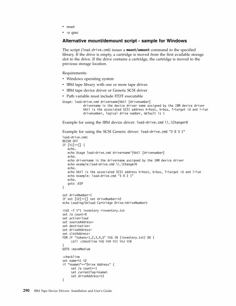
v resetv -o qmc
Alternative mount/demount script - sample for Windows
The script (load.drive.cmd) issues a mount/umount command to the specifiedlibrary. If the drive is empty, a cartridge is moved from the first available storageslot to the drive. If the drive contains a cartridge, the cartridge is moved to theprevious storage location.
Requirements:v Windows operating systemv IBM tape library with one or more tape drivesv IBM tape device driver or Generic SCSI driverv Path variable must include ITDT executableUsage: load-drive.cmd drivername|hbtl [drivenumber]
drivername is the device driver name assigned by the IBM device driverhbtl is the associated SCSI address h=host, b=bus, T=target id and l=lundrivenumber, logical drive number, default is 1
Example for using the IBM device driver: load-drive.cmd \\.\Changer0
Example for using the SCSI Generic driver: load-drive.cmd "2 0 3 1"load-drive.cmd:@ECHO OFFIF [%1]==[] (
echo.echo Usage load-drive.cmd drivername^|hbtl [drivenumber]echo.echo drivername is the drivername assigned by the IBM device driverecho example:load-drive.cmd \\.\Changer0echo.echo hbtl is the associated SCSI address h=host, b=bus, T=target id and l=lunecho example: load-drive.cmd "3 0 2 1"echo.goto :EOF
)
set driveNumber=1IF not [%2]==[] set driveNumber=%2echo Loading/Unload Cartridge Drive:%driveNumber%
itdt -f %~1 inventory >inventory.txtset /a count=0set action=loadset sourceAddress=set destination=set driveAddress=set slotAddress=FOR /F "tokens=1,2,3,4,5" %%G IN (inventory.txt) DO (
call :checkline %%G %%H %%I %%J %%K)GOTO :moveMedium
:checklineset name=%1 %2if "%name%"=="Drive Address" (
set /a count+=1set currentTag=%name%set driveAddress=%3
)
290 IBM Tape Device Drivers: Installation and User's Guide

if "%name%"=="Media Present" (rem echo full drive addr:%driveAddress% slot addr:%slotAddress%action:%action% source:%sourceAddress% Tag:%currentTag%
if "%count%"=="%driveNumber%" if "%currentTag%"=="Drive Address" if "%4"=="Yes" (set action=unloadset sourceAddress=%driveAddress%
)
if "%count%"=="%driveNumber%" if "%currentTag%"=="Drive Address"if not "%4"=="Yes" (
set action=loadset destination=%driveAddress%
)
if "%sourceAddress%"=="" if "%currentTag%"=="Slot Address"if "%action%"=="load" if "%4"=="Yes" (
set sourceAddress=%slotAddress%)
)
if "%name%"=="Source Element" (if "%count%"=="%driveNumber%" if "%currentTag%"=="Drive Address"if "%action%"=="unload" (
set destination=%5)
)
if "%name%"=="Slot Address" (set currentTag=%name%set slotAddress=%4
)
GOTO:EOF:moveMediumecho %action% move media from %sourceAddress% to destination %destination%itdt -f %~1 move %sourceAddress% %destination%del inventory.txtGOTO:EOF
Standard Edition scripting commands: known limitations anddeviations
The scripting commands idp, sdp, fdp, and qrypart are currently only supportedby LTO 5, LTO 6, LTO 7, TS1140, and TS1150 drives.
When scripting, one must be aware of the following general deviations to thelegacy tapeutil scripting command set.
The Verbose Mode parameter is ignored for the ITDT-SE implementation; insteadalways the full information is printed.
For some operations, the sense data length is limited to 32 bytes - this length isrequired by the ITDT test sequences.
The list command does not work on Linux variants where the reported maximumSCSI transfer size is larger than the size the system can actually transfer.
Because ITDT-SE opens the device read/write by default in scripting mode, theWORM mode cannot be deactivated in scripting mode. Use the Tapeutil interactivemode instead to deactivate the WORM mode.
Scripting mode command deviations to legacy tapeutil (tapeutil is not changed):
Chapter 9. IBM Tape Diagnostic Tool (ITDT) 291
|
1. The erg (Erase Gap) command is not supported.2. The mtdevice command is not supported.3. The tell command is not supported.4. The seek command is not supported.5. The format command is not supported.6. The -o qsn command is not supported.7. path/querypath/path / qrypath / checkpath / - o phs - output: always
show all paths.The command is valid only in combination with an IBM device driver.
8. devinfo - different output (decoded on all platforms)9. inquiry - different output on Linux (like AIX in hex)
10. vpd - different behavior on Solaris (like AIX)11. modepage - HP-UX and Solaris output deviations (like AIX)12. inventory - additional parameters on AIX available on all platforms13. cartridgelocation - AIX parameter deviation available on all platforms14. mediainfo - different output --> decode on all platforms
The command is valid only in combination with an IBM device driver.15. setpos - logical versus physical position, only set logical position as on AIX16. HPUX: -o gpo -t 1|2 --> parameter -t1|2 (logical, physical) is not
supported.17. density - output all information on all platforms18. setparm (new) - work around the inability to set all parameters on all
platforms except the undocumented HP-UX release19. getparms (new) - retrieve all parameters on all platforms, independent of flag
set20. qryinquiry - output the same as on AIX21. logsense - does not output header with device/serial/volid, example:
05/12/09 15:10:44 Device: ULT3580- S/N: 1300000206 Volid: UNKNOWN
22. erase - does not work on i5/OS because of operating system limitation.23. Using -w x parameter without the necessary open leads to a core at least on
Solaris.
IBM Tape Diagnostic Tool - Graphical Edition
Installing ITDT - Graphical Edition
Installing ITDT-GE on Windows operating systems
To install ITDT-GE on Windows, download the executable fileinstall_ITDT_GE_<version>.exe on a directory of your choice.
Double-click the downloaded file to start the installer application.
ITDT-GE installer automatically uninstalls any previous version before the currentone is installed.
For the graphical user interface (GUI), a minimum screen resolution of 1024*768pixels is required.
292 IBM Tape Device Drivers: Installation and User's Guide

The supported Windows operating systems for ITDT-GE arev Microsoft Windows Server 2008 SP2 (x86, 32 bit)v Microsoft Windows Server 2008 R2 (x64, 64 bit)v Microsoft Windows 7 SP1 (x86, 32 bit)v Microsoft Windows 7 SP1(x64, 64 bit)
Installing ITDT-GE on Linux operating systems
To install ITDT-GE on Linux, download the executable fileinstall_ITDT_GE_<version>.bin to a directory of your choice.
install_ITDT_GE_<version>.bin must be run by a user with root access rights.
The ITDT-GE installer automatically uninstalls any previous version before thecurrent one is installed.
For the graphical user interface (GUI) a minimum screen resolution of 1024*768pixels is required. The supported Linux operating systems for ITDT-GE arev Linux Distributions with glibc 2.2.5 and higher.
Graphical Edition - known issues and limitations
This section describes the known issues and limitations of ITDT-GE.
Linux operating systems
It is recommended to not operate Security Enhanced Linux (SELinux) in enforcingmode while ITDT-GE is running.
On RedHat Enterprise Linux 4 and 5 and SuSE Enterprise Linux 10, starting theonline help might cause an error message Problems opening link / Unable toopen web browser on {0}. Workarounds are to issue the commandsa) ln -s /usr/bin/firefox /usr/local/bin/mozillaorb) export MOZILLA_FIVE_HOME=/usr/lib/firefox<version>
Replace with the appropriate path to your installed Firefox version before ITDT-GEis started.
Gnome desktop
If you are using the Gnome desktop, be sure to log in to the desktop session asroot to use ITDT-GE to prevent device access issues.
Windows operating systems
On Microsoft Windows systems where the maximum transfer size is limited to lessthan 64 kB, the Dump and Firmware update operations do not work.
Performance issues
If you are using Adaptec SCSI Host Bus Adapters, ensure that you are using thelatest Adaptec Host Bus Adapter Drivers instead of the drivers that are shippedwith the Windows operating system.
Chapter 9. IBM Tape Diagnostic Tool (ITDT) 293

Devices disappear after firmware update
After a firmware update, devices might disappear. This issue is a known Windowsproblem.
See the Article ID: 812024 at http://support.microsoft.com/kb/812024/en-us
Repeated Scan operations might help to rediscover the device.
All supported operating systems
Command timeout
There is no instant operation termination upon SCSI command timeout. Forexample, when the SCSI cable is unplugged after POST A is started.
When a command timeout condition occurs, ITDT might still continue to run moreoperations (like unmounting the cartridge) instead of instantly terminating with atimeout condition.
3576/TS3310 tape library
Library Firmware Update with ITDT-GE is not supported by the 3576/TS3310 tapelibrary. Update the firmware by using the 3576/TS3310 Web User Interface.
3494 tape library
Drives in a 3494 tape library or an STK silo library are supported. Only the Testoption does not work because of device-specific restrictions for handling cartridges.
ITDT-GE user interface description
To start ITDT-GE on Windows, click the shortcut that is created by the installationprocess. On Linux, no start menu entry is generated. Start ITDT-GE by opening aTerminal window, then switch to root user.$ su -
a2500238
Figure 51. Graphical Edition user interface
294 IBM Tape Device Drivers: Installation and User's Guide

Finally, start ITDT-GE with$ /opt/ibm/itdt-ge/itdt-ge
The User Settings dialog box displays the first time that the program is run,allowing the entry of user specifications: User name, company name, output path,and log level.
The Output Path defines the location where the test reports and dumps are saved.The Windows default output path isC:\Documents and Settings\<username>\.itdt-ge\output
orC:\Users\<username>\.itdt-ge\output
where <username> is the Windows user login name. The Linux default outputpath is/root/.itdt-ge/output
The Log Level must not be changed unless requested to do so by the IBM SupportCenter. It is recommended that this information be provided to allow for furtheranalysis of test results.
The ITDT-GE interface contains the following sections:
a2500279
Figure 52. Graphical Edition preferences
Chapter 9. IBM Tape Diagnostic Tool (ITDT) 295

v Main menu (▌1▐ on Figure 53)- in upper left (File, Window, Help) The followingmain program menu items are available:
v Control Center (▌2▐ on Figure 53) - On left side (Device operations - Scan, Test,Dump, and Update)Extra device operations are available by using drop-down arrows.
v Test Lab (▌3▐ on Figure 53) - Located from center to right side (Contains runningand previously run tests)
v Status Information (▌4▐ on Figure 53) - Located below the Test Lab (Containssummary results of tests)
The Control Center is the primary section the ITDT-GE operations.
The following toolbar buttons for the device operations are available.
a2500239
1
2
3
4
Figure 53. Graphical Edition interface
a2500264
Figure 54. Main program menu items
296 IBM Tape Device Drivers: Installation and User's Guide
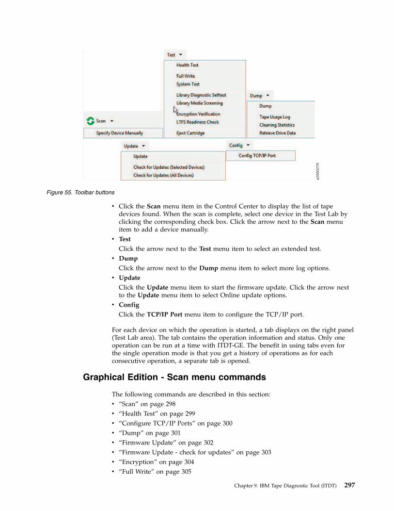
v Click the Scan menu item in the Control Center to display the list of tapedevices found. When the scan is complete, select one device in the Test Lab byclicking the corresponding check box. Click the arrow next to the Scan menuitem to add a device manually.
v Test
Click the arrow next to the Test menu item to select an extended test.v Dump
Click the arrow next to the Dump menu item to select more log options.v Update
Click the Update menu item to start the firmware update. Click the arrow nextto the Update menu item to select Online update options.
v Config
Click the TCP/IP Port menu item to configure the TCP/IP port.
For each device on which the operation is started, a tab displays on the right panel(Test Lab area). The tab contains the operation information and status. Only oneoperation can be run at a time with ITDT-GE. The benefit in using tabs even forthe single operation mode is that you get a history of operations as for eachconsecutive operation, a separate tab is opened.
Graphical Edition - Scan menu commands
The following commands are described in this section:v “Scan” on page 298v “Health Test” on page 299v “Configure TCP/IP Ports” on page 300v “Dump” on page 301v “Firmware Update” on page 302v “Firmware Update - check for updates” on page 303v “Encryption” on page 304v “Full Write” on page 305
a2500275
Figure 55. Toolbar buttons
Chapter 9. IBM Tape Diagnostic Tool (ITDT) 297

v “Tape Usage” on page 307v “System Test” on page 307v “Library Diagnostic Self-Test” on page 309v “Library Media Screening” on page 309v “LTFS Readiness Check” on page 309v “Manual Inspection Record Entry” on page 309
Scan
The scan function is used to discover all supported tape and library devices thatare attached to the computer system. Then, they can be selected for the subsequentITDT-GE operations. The scan function also serves as a connection test that can beused to verify correct attachment of the devices.
Note: When Scan is pressed for the first time, a dialog box is displayed that warnsthe user to stop all backup jobs.
When the scan is finished, the device list is displayed in the Control Center area.
A scroll bar is available to show all the devices. When the device you want isdisplayed, select the device for test. Only one device can be selected.
a2500240
Figure 56. Scan
298 IBM Tape Device Drivers: Installation and User's Guide

Health Test
The Health Test function checks if the tape device is defective and outputs apass/fail result.
Attention:
1. The test functionality erases user data on the cartridge that is used for the test.2. The test can take from 15 minutes up to 2 hours.3. The test runs only on tape drives, not on autoloaders or libraries.
To start the Health Test function, it is recommended that a new or rarely usedcartridge is used. Scaled (capacity-reduced) cartridges must not be used to test thedevice.
To test tape drives within a library, the library must be in online mode.
After the device is selected, start the Health Test function by selecting the HealthTest menu item.
The Health Test function can be stopped by clicking Abort.
Note: It can take some time until the Health Test function stops.
a2500241
Figure 57. Test
Chapter 9. IBM Tape Diagnostic Tool (ITDT) 299
|
|
|
|
|

Note: Information can be found in the .txt/.blz files. See the log file section (▌1▐).
The test sequence contains the following steps:1. Initialize Drive2. Read Thermal Sensor3. Mount Medium4. [Medium Qualification] – only if previous step indicated requirement5. Load/Write/Unload/Read/Verify6. POST A7. Performance Test (run 2 times if first run failed with performance failure)8. Unmount Medium9. Read Thermal Sensor
10. Get FSC11. Get Logs
Configure TCP/IP Ports
For LTO 5, LTO 6, LTO 7, TS1140, and TS1150 drives, the ethernet port settings canbe configured with the Configure TCP/IP Port command. The Configure TCP/IPPort command displays the current settings:
a2500242
1
Figure 58. Test results
300 IBM Tape Device Drivers: Installation and User's Guide
|

After you click Apply, the new values are set and the updated values display.
Note: Because earlier drive generations do not have an ethernet port, theConfigure TCP/IP Ports command is rejected for these devices with the followingmessage:TCP/IP configuration is not supported on this product.
Dump
After the device you want to dump is selected, start the Dump function byselecting Dump > Dump from the actions toolbar.
When the dump process is run on a tape library or autoloader other than the3584/TS3500/TS4500, the Dump function stores 1 log file in the output folder ofthe program (*.blz). For the 3584/TS3500/TS4500, a dump file (*.a) is stored in theoutput folder. Both files start with the serial number of the device (▌1▐).
a2500274
Figure 59. Configure TCP/IP Ports
Chapter 9. IBM Tape Diagnostic Tool (ITDT) 301
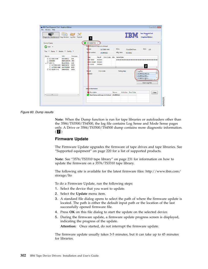
Note: When the Dump function is run for tape libraries or autoloaders other thanthe 3584/TS3500/TS4500, the log file contains Log Sense and Mode Sense pagesonly. A Drive or 3584/TS3500/TS4500 dump contains more diagnostic information.(▌2▐)
Firmware Update
The Firmware Update upgrades the firmware of tape drives and tape libraries. See“Supported equipment” on page 220 for a list of supported products.
Note: See “3576/TS3310 tape library” on page 231 for information on how toupdate the firmware on a 3576/TS3310 tape library.
The following site is available for the latest firmware files: http://www.ibm.com/storage/lto
To do a Firmware Update, run the following steps:1. Select the device that you want to update.2. Select the Update menu item.3. A standard file dialog opens to select the path of where the firmware update is
located. The path is either the default input path or the location of the lastsuccessfully opened firmware file.
4. Press OK on this file dialog to start the update on the selected device.5. During the firmware update, a firmware update progress screen is displayed,
indicating the progress of the update.Attention: Once started, do not interrupt the firmware update.
The firmware update usually takes 3-5 minutes, but it can take up to 45 minutesfor libraries.
a2500225
1
2
Figure 60. Dump results
302 IBM Tape Device Drivers: Installation and User's Guide

Note: If ITDT-GE detects a FIPS-certified drive firmware, it shows a warningdialog message. Before you continue, ensure that you use a FIPS-certified firmwareto update the drive.
Firmware Update - check for updates
ITDT-GE can Check for Device Updates for IBM tape drives and IBM tapelibraries. You can choose to select either one device or all devices by selecting thecorresponding option from the drop down menu under Update in the ITDTControl Center.
The program connects to IBM FixCentral and identify updates for the devices. Ifthe connection cannot be established or another problem occurred, the problemdescription is shown at the bottom of "FixCentral" Test Tab.
In the sample above, the drive has two FixCentral components. Each componenthas several items; such as code files and textual meta information.
The code files (binary files) have a "+" in the icon to distinguish and can bedownloaded either by double-clicking or by using the right mouse button. The textfiles (for example, readme files) can be viewed in the same way. A separate TestTab is opened and the information shown.
For tape drives an available code is colored:v GREEN: the code level is newer than the one of the drive.v RED: the code level is older than the one of the drive.v BLUE: the code level is the same as the one of the drive.
For automation drives (drives in a library), both devices are used. A code level foran automation drive is directly linked to a code level of a library.
a2500289
Figure 61. Check for Device Updates - FixCentral components
Chapter 9. IBM Tape Diagnostic Tool (ITDT) 303
||
|

Encryption
Note: The test that is shown on the graphic was run on a non-encrypted deviceand is showing a failure.
a2500290
Figure 62. Check for Device Updates - code level
a2500226
Figure 63. Encryption
304 IBM Tape Device Drivers: Installation and User's Guide

The Encryption function is used to verify whether data on the cartridge is writtenencrypted. It reads both decrypted and raw data from the cartridge into twoseparate files on disk. The user can then verify that the data differs to ensure thatencryption worked.
The Encryption function is only supported on encryption enabled drives andrequires an encryption infrastructure, including the Encryption Key Manager(EKM) to be properly set up.1. After the device you want to test is selected, start the encryption function by
selecting Test > Encryption Verification from the actions toolbar.2. ITDT-GE then shows the Encryption Verification screen. On this screen, the
system requires the entry of the number of the start record and the amount ofdata (in KB) to be read.
3. Enter the required values and click OK to start the encryption.The Encryption function can be stopped by clicking Abort.
Note: It can take some time until the Encryption function stops.
Table 54 on page 250 defines the abort codes.
Full Write
The Full Write function writes the entire cartridge with a specified block size eitherwith compressible or incompressible data and output performance data.
Attention:
1. The Full Write function erases data on the cartridge that is used for the test.2. The Full Write function takes approximately 2 hours when incompressible data
is written, less time for compressible data.3. The Full Write function runs only on tape drives, not on autoloaders or
libraries.
The Full Write test can be used tov Demonstrate that the drive can write the full amount of data on a cartridge.v Reveal system performance bottlenecks.
Full Write runs the test with incompressible data first, then runs the test withcompressible data. If no difference in overall performance is observed, abandwidth limitation might be caused by the system or cabling or HBA.
v Identify system issues with compression.Compression is always turned on during the full write. When run withcompressible data, the output shows the compression rate. If it is higher than 1.0but your system is not able to compress data on the cartridge, check your devicedriver and software settings to see whether they disable compression.
To run a full write on tape drives within a library, the library must be in onlinemode.1. After the device you want to write to is selected, start the Full Write function
by selecting Test > Full Write from the actions toolbar.2. Click OK to start the full write.3. ITDT-GE then shows the Full Write screen. If no cartridge is inserted, ITDT-GE
prompts you to insert a cartridge. Either insert a cartridge and click OK or stopby clicking Abort.
Chapter 9. IBM Tape Diagnostic Tool (ITDT) 305

Note: If ITDT-GE detects data on the cartridge, it shows the following message.
Click Yes to continue the test if you are sure that data on the cartridge can beoverwritten. If you are unsure, click No to stop the test.
4. The system prompts for entry of a transfer size between 16 KB and themaximum block size that is supported by the system. Maximum value is 512KB. Select the appropriate value for your system.
5. Select the type of data to write, either [C] Compressible or [I] Incompressible.The full write can be stopped by clicking Abort.
Note: It can take some time until the full write actually stops."Compressible = Yes" means that the data written was just zeros so that thedata can be compressed by the drive with a maximum compression ratio."Compressible = No" means that a data pattern was written that the drive
a2500227
Figure 64. Overwrite data?
a2500228
Figure 65. Transfer size
306 IBM Tape Device Drivers: Installation and User's Guide

almost cannot compress at all. If the compression ratio is 1, the drive was notable to compress the data (equivalent to 1:1 compression ratio). If thecompression ratio is 94.0, the drive was able to do 94:1 compression. It meansthat 94 bytes in the original data was compressed to 1 byte on the medium.100.0 means 100 bytes is compressed down to 1 byte on the medium.If all write operations are finished, ITDT-GE shows the performance statisticsfor the selected block size that is written on the cartridge, in the StatusInformation area. If an error occurred during the full write, data is onlypartially written.
Tape Usage
The Tape Usage function retrieves statistical data and error counters from acartridge.1. After the device you want to test is selected, start the Tape Usage function by
selecting Dump > Tape Usage Log from the actions toolbar.2. ITDT-GE then shows the tape usage screen. If no cartridge is inserted, ITDT-GE
prompts you to insert a cartridge. Either insert a cartridge and click OK or stopby clicking Abort.
System Test
The System Test is a short test that runs the following tests:v Reveals system performance bottlenecks. Compressible data throughput values
can reveal bandwidth limitations that are caused by the system or cabling orHBA.
v Measures performance variations across the different block sizes to find the idealblock size for the system configuration.
a2500229
Figure 66. Tape Usage
Chapter 9. IBM Tape Diagnostic Tool (ITDT) 307

The System Test runs only on tape drives, not on autoloaders or libraries. To run aSystem Test on tape drives within a library, the library must be in online mode.
After the device you want to test is selected, start the System Test function byselecting Test > System Test from the actions toolbar.
ITDT-GE then shows the System Test screen. If no cartridge is inserted, ITDT-GEprompts you to insert a cartridge. Either insert a cartridge and click OK or stop byclicking Abort.
Note: If ITDT-GE detects data on the cartridge, it shows the following message -Cartridge not empty!
Overwrite data?
Click Yes to continue the test if you are sure that data on the cartridge can beoverwritten. If you are unsure, click No to stop the test.
The System Test is run as follows:1. System Test determines the amount of data to write for each supported
blocksize (a percentage of the cartridge is written for each blocksize).2. The test determines the maximum supported blocksize of the system.3. System Test writes the amount of data with all supported block sizes in powers
of two down to 64 KB (values of 16 KB and 32 KB are not tested in cases wherethe capability of a system supports higher block sizes). It begins with themaximum supported blocksize that is detected before, first with incompressible,next with compressible data. Then, it shows performance data and a progressscreen.
4. At the end of the test, a summary information is shown.
a2500230
Figure 67. System Test
308 IBM Tape Device Drivers: Installation and User's Guide
||

Library Diagnostic Self-Test
The Library Self-Test starts and monitors the library-internal self-test. This test runsonly on libraries and autoloaders, not on tape drives.
After the device you want to test is selected, start the Library Self-Test function byselecting Test > Library Diagnostic Self-Test from the actions toolbar.
At the end of the test, the results are shown in the Status Information area.
Library Media Screening
The Automated Library Media Screening test generates dumps for each drive andcartridge within a library. It runs only on libraries (except TS3500/TS4500) andauto-loaders, not on tape drives.
First, the test tries to read dump files from each drive that is installed from thelibrary. Then, you can select one drive for loading the cartridges.
All cartridges of the I/O and storage slots are moved - one after the other fromtheir source to the selected drive. A dump is taken and moved back to the sourceaddress. In the result screen, the dumps taken and the count of dumps are shown.
LTFS Readiness Check
The LTFS Readiness Check analyzes the Operating System and tape driveenvironment to ensure that the IBM Linear Tape File system can be installed. Forextended information, refer to “Check LTFS Readiness” on page 247.
Manual Inspection Record Entry
A manual inspection record can be generated if the device does not show in thedevice list. This test is intended for devices that are not recognized or have atechnical problem that cannot be determined by ITDT-GE.
If a tape drive cannot be identified by using a device scan, the user can manuallycreate a test record for the drive. The system prompts the user to run the SCSI/FCWrap test for the drive (see the service manual for the drive). The results of thewrap test can be entered along with extra inspection information. The results aresaved into binary and text output files that have the same format as the outputfiles generated by the test.1. From the Main Program menu, select File > Manual Record.2. Enter the required information to complete the items in the screen.
a. Enter the device serial number.b. Enter the content of the Message Display.c. Optionally, enter any information text.
3. After all information is entered, click OK.The information is stored in a binary file (which can be used for furtheranalysis), and in a human-readable text file. Both files are stored in theITDT-GE output folder.
Copy Services
With Copy and Migration Services, tape content can either be copied or movedv From a cartridge to another cartridge
Chapter 9. IBM Tape Diagnostic Tool (ITDT) 309
v From a cartridge to an image file, orv From an image file to a cartridge.
The tool offers different use cases like copying data or migrating data from onegeneration to another. That is, data can be copied from a Gen4 cartridge to a Gen5cartridge. Even migration from an LTO to IBM Enterprise Tape Systems issupported. For an LTFS environment, the data can be copied or moved with theLTFS Physical copy that adjusts the LTFS parameter on the target to be unique.Such a copy can be used in the same LTFS environment as the source. To ensuremaximum performance for tape to tape copy actions, ITDT allocates a read bufferwhich calculates to 2500 multiplied by the maximum supported system blocksize.If the system does not provide this buffer, the operation is aborted with MEMORYALLOCATION FAILED.
Tape Physical Copy
Creates a physical copy of a tape cartridge either to another cartridge or to animage file. The created cartridge has the same physical layout and contents as thesource cartridge. Tape Physical Copy supports LTO and 3592 tape drives and cantherefore be used for data migration. A copy from a previous generation to anewer generation cartridge and from an LTO to a 3592 works. However, theamount of used data from the source device must be equal or less than thecapacity of the destination device. If the source cartridge is partitioned, the targetmust support the same partitioning sizes and amount. The amount of transferreddata and the current data transfer rate is displayed every 3-5 minutes.
LTFS Physical Copy
Creates a physical copy of an LTFS formatted cartridge. The LTFS specifiedparameters volumeuuid and VCI are adjusted during this copy operation. Thecreated cartridge has the same physical layout as the origin cartridge. Expect thevolumeuuid to be identical to the contents of the two cartridges. The amount oftransferred data and the current data transfer rate is displayed every 3-5 minutes.When 'LTFS Physical Copy' is used with a non-LTFS formatted cartridge, thebehavior is identical to 'Tape Physical Copy'.
Verify
Verifies the physical contents of two cartridges. The physical data layout and thebinary data are compared.
Usage
By opening the "Copy Services" perspective, the user can run a 'Scan...' to discoverattached devices.
310 IBM Tape Device Drivers: Installation and User's Guide
|||||
||

A cartridge can be loaded or unloaded by double-clicking or pressing the rightmouse button on the drive that is used for the copy tasks. When a cartridge isloaded, the cartridge Serial Number or the VOLSER in a library environment isshown. If a cartridge or an image file is selected on the left, it can be used as"Source" by pushing Select Source. After the 'Source" is selected, the target can bechosen. To select the target, either a different cartridge in a different drive or theimage file folder can be selected. By pressing Select Target, the target is set on theright.
If the source and the target are selected, the Copy Services or a verification can bestarted regarding the used Mode: “Tape Physical Copy” on page 310, “LTFSPhysical Copy” on page 310, or “Verify” on page 310.
Graphical Edition - visualizing log files
ITDT-GE offers the opportunity to visualize the content of DUMP and ITDT logfiles (BLOB files).v Dump files can be retrieved with ITDT or any other tool that supports this
function.v Dump files that are generated by ITDT have the suffix ".a" or ".b".v BLOB files are generated during the run of an ITDT test sequence, such as
"Standard Test".v BLOB files have the suffix ".blz".v Both file types can be opened and visualized with ITDT-GE.
a2500294
Figure 68. Copy Services
Chapter 9. IBM Tape Diagnostic Tool (ITDT) 311
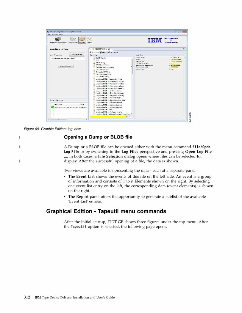
Opening a Dump or BLOB file
A Dump or a BLOB file can be opened either with the menu command File/OpenLog File or by switching to the Log Files perspective and pressing Open Log File.... In both cases, a File Selection dialog opens where files can be selected fordisplay. After the successful opening of a file, the data is shown.
Two views are available for presenting the data - each at a separate panel.v The Event List shows the events of this file on the left side. An event is a group
of information and consists of 1 to n Elements shown on the right. By selectingone event list entry on the left, the corresponding data (event elements) is shownon the right.
v The Report panel offers the opportunity to generate a sublist of the available'Event List' entries.
Graphical Edition - Tapeutil menu commands
After the initial startup, ITDT-GE shows three figures under the top menu. Afterthe Tapeutil option is selected, the following page opens.
a2500286
Figure 69. Graphic Edition: log view
312 IBM Tape Device Drivers: Installation and User's Guide
|
|
|
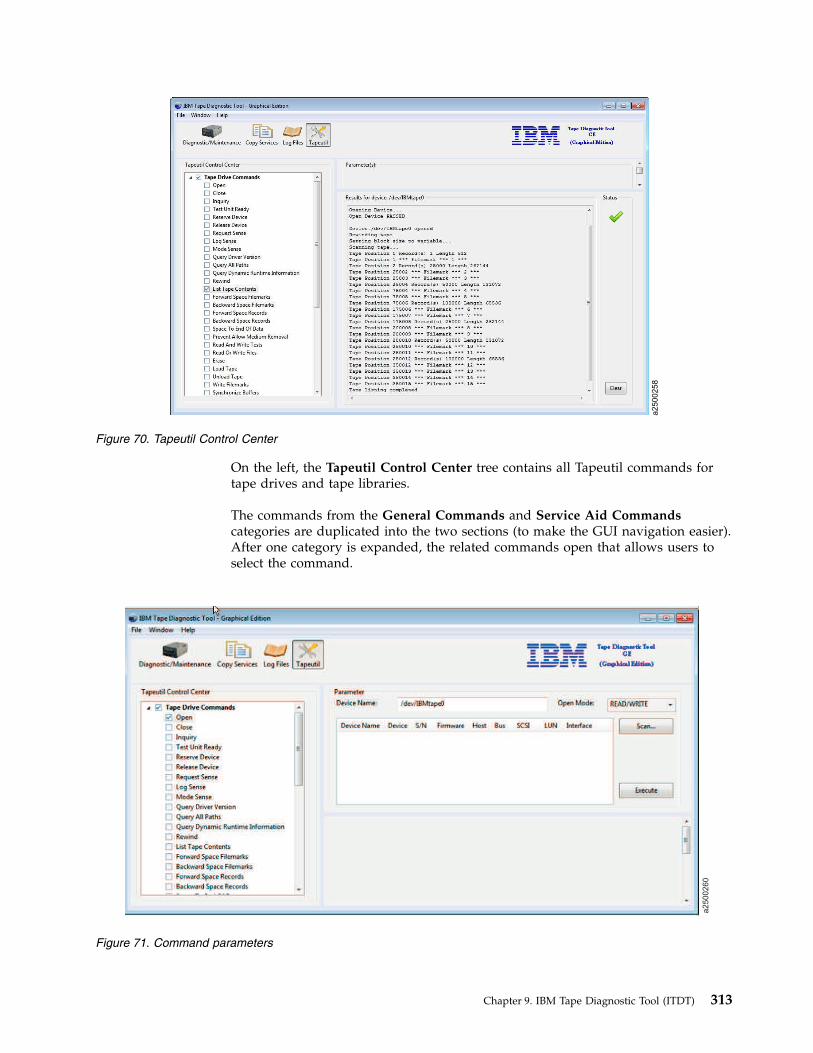
On the left, the Tapeutil Control Center tree contains all Tapeutil commands fortape drives and tape libraries.
The commands from the General Commands and Service Aid Commandscategories are duplicated into the two sections (to make the GUI navigation easier).After one category is expanded, the related commands open that allows users toselect the command.
a2500258
Figure 70. Tapeutil Control Center
a2500260
Figure 71. Command parameters
Chapter 9. IBM Tape Diagnostic Tool (ITDT) 313

When the user presses Execute, the Results output is placed below the Parametersection:
The Open command has a Scan ... button in the Parameter view. Pressing Scan...runs a scan on the host and shows the attached devices in the Result View at thebottom. This information is helpful to identify the right Device Name for the openfunction field Device Name.
a2500261
Figure 72. Command parameter results
a2500287
Figure 73. Generic tapeutil scan
314 IBM Tape Device Drivers: Installation and User's Guide
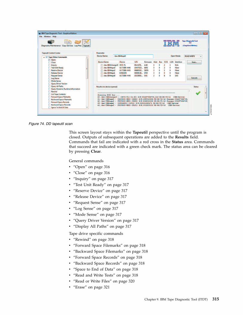
This screen layout stays within the Tapeutil perspective until the program isclosed. Outputs of subsequent operations are added to the Results field.Commands that fail are indicated with a red cross in the Status area. Commandsthat succeed are indicated with a green check mark. The status area can be clearedby pressing Clear.
General commandsv “Open” on page 316v “Close” on page 316v “Inquiry” on page 317v “Test Unit Ready” on page 317v “Reserve Device” on page 317v “Release Device” on page 317v “Request Sense” on page 317v “Log Sense” on page 317v “Mode Sense” on page 317v “Query Driver Version” on page 317v “Display All Paths” on page 317
Tape drive specific commandsv “Rewind” on page 318v “Forward Space Filemarks” on page 318v “Backward Space Filemarks” on page 318v “Forward Space Records” on page 318v “Backward Space Records” on page 318v “Space to End of Data” on page 318v “Read and Write Tests” on page 318v “Read or Write Files” on page 320v “Erase” on page 321
a2500288
Figure 74. DD tapeutil scan
Chapter 9. IBM Tape Diagnostic Tool (ITDT) 315

v “Load Tape” on page 321v “Unload Tape” on page 321v “Write Filemarks” on page 321v “Synchronize Buffers” on page 321v “Query/Set Parameter” on page 321v “Query/Set Position” on page 321v “Query Encryption Status” on page 322v “Display Message” on page 322v “Display All Paths” on page 317v “Report Density Support” on page 322v “Test Encryption Path” on page 323
Tape library-specific commandsv “Element Information” on page 323v “Position to Element” on page 323v “Element Inventory” on page 323v “Exchange Medium” on page 324v “Move Medium” on page 324v “Initialize Element Status” on page 324v “Prevent/Allow Medium Removal” on page 324v “Initialize Element Status Range” on page 324v “Read Device IDs” on page 324v “Read Cartridge Location” on page 324
Service aid commandsv “Configure TCP/IP Ports” on page 325v “Dump/Force Dump/Dump” on page 325v “Firmware Update” on page 325
Note: When a command is issued in Tapeutil mode for ITDT GE, Execute must bepressed before the action takes place.
Open
When you select the Open command:1. ITDT checks if a device is already opened.2. Under Device Name:, enter the name of the device in the box.3. In the Open Mode menu, select how to open the device (rw, ro, wo, append).4. ITDT opens the device that you selected.
Note: Always use the Read Only mode when you are working withwrite-protected media.
Close
When you select the Close command1. ITDT checks if the device is already closed.2. ITDT closes the device.
316 IBM Tape Device Drivers: Installation and User's Guide

Inquiry
When you select the Inquiry command1. You are prompted for page code.2. ITDT then displays a decoded format of a hexadecimal dump and prints a
hexadecimal dump of the inquiry data.
Test Unit Ready
When you select the Test Unit Ready (TUR) command, ITDT issues the Test UnitReady ioctl command.
Reserve Device
When you select the Reserve Device command, ITDT issues a reserve commandfor the device.
Release Device
When you select the Release Device command, ITDT issues a release command forthe device.
Request Sense
When you select the Request Sense command1. ITDT issues a Request Sense command.2. ITDT then displays a decoded format of hexadecimal dump sense data and
prints hexadecimal dump sense data.
Log Sense
When you select the Log Sense command1. Enter the page number, in hexadecimal, in the Page-Code field.2. ITDT issues a Log Sense command and outputs a hexadecimal dump of that
page.
Mode Sense
When you select the Mode Sense command1. Enter the page number, in hexadecimal, in the Page-Code field.2. ITDT issues a Mode Sense command and outputs a hexadecimal dump of that
page.
Query Driver Version
When you select the Query Driver Version command1. ITDT issues the required command to get the driver version.2. ITDT prints the driver version.
Display All Paths
When you select the Display All Paths command1. ITDT issues an ioctl command.2. ITDT outputs decoded path information for all paths.
Chapter 9. IBM Tape Diagnostic Tool (ITDT) 317

Rewind
When you select the Rewind command, ITDT issues the ioctl rewind command forthe device.
Forward Space Filemarks
When you select the Forward Space Filemarks command1. Enter the amount of filemarks to forward space, in the Filemark-Count box.2. ITDT issues (extrinsic) ioctl command.3. The tape is positioned on the first block of the next file.
Backward Space Filemarks
When you select the Backward Space Filemarks command1. Enter the amount of filemarks to backward space, in the Filemark-Count box.2. ITDT issues (extrinsic) ioctl command.3. The tape is positioned on the last block of the previous file.
Forward Space Records
When you select the Forward Space Records command1. Enter the amount of records to forward space, in the Record-Count box.2. ITDT issues (extrinsic) ioctl command.
Backward Space Records
When you select the Backward Space Records command1. Enter the amount of records to backward space, in the Record-Count box.2. ITDT issues (extrinsic) ioctl command.
Space to End of Data
When you select the Space to End of Data (EOD) command, ITDT issues the(extrinsic) ioctl command.
Read and Write Tests
When you select the Read and Write Tests command, ITDT runs the followingfunctions (Read and Write Test, Read Only Test, and Write Only Test). Threeparameter fields have default values already in them. Next, a Test menu that givesyou the option of Read Data from Tape, Write Data to Tape, andRead/Write/Verify.
Note: The default is a block size of 10240 bytes, a count of 20 blocks, and arepetition of 1. If the block size is zero, variable mode is used. With a fixed blocksize, a data amount of (block size * blocks) is transferred with a single operation.This operation might get rejected if the total amount exceeds the transfer size ofthe system.The following steps are run, depending on which test is selected.v The Read/Write steps:
1. Issues a Read Position.2. Sets block size.3. Generates special pattern.
318 IBM Tape Device Drivers: Installation and User's Guide

4. Puts block id in bytes 0-3 of each block.5. Prints current block number, number of bytes and blocks.6. Issues write command.7. Prints updated statistics.8. If number of bytes written is different from requested bytes to write, stop
(go to Step 19).9. Writes two filemarks.
10. Backward spaces two filemarks.11. Backward spaces number of records written.12. Prints amount of data to read.13. Issues read command.14. If read error occurred or number of bytes read is different from requested
number of bytes to read, go to Step 19.15. Compares data that is read with data written, show miscompares and if
miscompares exist, stop (go to Step 19).16. If compare is OK, print OK message.17. Forward space one file mark.18. Repeat Steps 10 - 24 until all blocks are written, or go to Step 4 until all
blocks are written.19. Prints current block id and total number of bytes written.
v The Read Only steps:1. Issues a Read Position.2. Sets block size.3. Generates special pattern.4. Print amount of data to read.5. Issues read command.6. If read error occurred or number of bytes read is different from requested
number of bytes to read, stop (go to Step 19).7. Compares data that is read with buffer data, show miscompares and if
miscompares exist, stop (go to Step 19).8. If compare is OK, print OK message.9. Repeat Steps 10 - 15 until all blocks are written, or go to Step 4 until all
blocks are written.10. Prints current block id and total number of bytes read.11. Backward spaces number of records written.12. Prints amount of data to read.13. Issues read command.14. If read error occurred or number of bytes read is different from requested
number of bytes to read, go to Step 19.15. Compares data that is read with data written, show miscompares and if
miscompares exist, stop (go to Step 19).16. If compare is Ok, print OK message.17. Forward space one file mark.18. Repeat Steps 10 - 24 until all blocks are written, or go to Step 4 until all
blocks are written.19. Prints current block id and total number of bytes written.
v The Write Only steps:
Chapter 9. IBM Tape Diagnostic Tool (ITDT) 319

1. Issues a Read Position.2. Sets block size.3. Generates special pattern.4. Put block id in bytes 0-3 of each block.5. Prints current block number, number of bytes and blocks.6. Issues write command.7. Prints updated statistics.8. If number of bytes written is different from requested bytes to write, stop
(go to Step 10).9. Repeat Steps 5 - 9 until all blocks are written, or to Step 4 until all blocks
are written.10. Print current block id and total number of bytes written.
Read or Write Files
When Read or Write Files is selected, a box under File Name: is where the pathand name of the file is entered. Under that is a box named Number of records toread (0 for entire file). The default amount in the box is 100. Next, a menu barunder Test: gives you the choice of Read File from Tape or Write File to Tape.Once the Test is selected, Browse appears next to the File Name box to allowbrowsing for the needed file. When you select the Read or Write Files command,ITDT runs the following functions:v Read steps:
1. Prompts if to read a file from tape2. You are prompted for destination file name3. You are prompted for number of records to read (If you press Enter, the
entire file is read.)4. Prints the file name to be opened5. Opens the file (r/w with large file support, 666 umask)6. Issues Query Parameters ioctl command, if it fails, quit7. Sets blocksize to maximum, variable blocksize mode8. Calculates the number of blocks to read.9. Prints number of records to read.
10. ITDT read from tape.11. Writes to file, stop if data count is not equal to data count requested.12. If more data to read, go to Step 10.13. Prints statistics.
v Write steps:1. Prompts if to write a file to tape.2. You are prompted for the source file name.3. Prints the file name to be opened.4. Opens the file (r/o with large file support).5. Issues Query Parameters ioctl command, if it fails, quits.6. Sets blocksize to maximum, variable blocksize mode7. Prints write statement.8. Reads from file.9. Writes to tape, stop if data counts written is not equal to data count
requested.
320 IBM Tape Device Drivers: Installation and User's Guide

10. Prints statistics.
Erase
When you select the Erase command, ITDT issues the (extrinsic) ioctl command.
Load Tape
ITDT issues a SCSI Load command to load a tape.
Unload Tape
When you select the Unload Tape command1. ITDT issues the (extrinsic) ioctl command.2. The tape rewinds and then unloads.
Write Filemarks
When you select the Write Filemarks command1. In the Filemark-Count box, enter the number of filemarks to write.2. ITDT issues the (extrinsic) ioctl command.
Synchronize Buffers
When you select the Synchronize Buffers command, ITDT issues the ioctlcommand.
Query/Set Parameter
When you select the Query/Set Parameter command1. ITDT shows the changeable parameters.
Note: The list of changeable parameters are operating system specific. For a listof changeable parameters, refer to Table 56 on page 279.
2. Select from the list of parameters that can be changed by clicking the choice.3. ITDT requests prompt for parameter value (if required).4. ITDT requests safety prompt (if required).5. ITDT issues the ioctl command.
Query/Set Position
When you select the Query/Set Position command1. ITDT prints the current position and requests the new position.
Note: ITDT does not distinguish between logical and physical position. Itshows the current position and queries for the one to set, then sets the newposition.
2. Enter the block id for where the tape must go. This block id must be enteredin decimal. When the tape is set, the block id is printed in decimal withhexadecimal in parentheses.
3. ITDT issues the Set Position ioctl and returns the pass or fail results.4. ITDT prints decoded logical position details.5. ITDT issues Query Physical Position ioctl command.6. ITDT prints decoded physical position details.
Chapter 9. IBM Tape Diagnostic Tool (ITDT) 321

7. You are prompted for position to set (logical or physical) or to stop.8. You are prompted for the block id in decimal or hexadecimal.9. ITDT prints a summary.
10. ITDT issues the Set Position ioctl command.11. Repeat steps 2 - 5.
Query Encryption Status
When you select the Query Encryption Status command1. ITDT issues Get Encryption State ioctl command.2. ITDT displays encryption settings (Drive EC, Encryption Method, Encryption
state).
Display Message
When you select the Display Message command1. ITDT provides Parameter boxes in which you can enter 1 or 2 messages up to
8 characters.
Note: Display Message works only on drives that have a display pane, the 3590and 3592 drives.
2. In the Type: menu, select which message (0 or 1) you want shown and if youwant it to flash. There is also an alternate (alt) selection that alternates betweenmessages.
3. ITDT issues the ioctl command.4. ITDT prints the displayed message.
Display All Paths
When you select the Display All Paths command1. ITDT issues an ioctl command.2. ITDT outputs decoded path information for all paths.
Report Density Support
When you select the Report Density Support command1. ITDT prints report status text for all supported media.2. ITDT issues Report Density Support ioctl command to retrieve all supported
media.3. ITDT prints all requested reports. Data is printed in a decoded way. Scroll the
screen to print each one of the following status texts:v Density namev Assigning organizationv Descriptionv Primary density codev Secondary density codev Write OKv Duplicatev Defaultv Bits per MMv Media Width
322 IBM Tape Device Drivers: Installation and User's Guide

v Tracksv Capacity (megabytes).
4. ITDT prints report status text for current media.5. ITDT issues Report Density Support ioctl command to retrieve current media.6. ITDT prints report data in a decoded way.
Test Encryption Path
When you select the Test Encryption Path command
Note: Not supported for the HP-UX operating system.1. ITDT prints status message that server configuration and connections are
tested.2. ITDT issues the Encryption Diagnostics ioctl command, Ping Diag.3. ITDT prints number of servers available or error message.4. ITDT issues the Encryption Diagnostics ioctl command, Basic Encryption
Diag.5. ITDT prints completion code or error message.6. ITDT issues the Encryption Diagnostics ioctl command, Full Encryption Diag.7. ITDT prints completion code or error message.
Element Information
When you select the Element Information command:1. ITDT issues the ioctl command.2. ITDT showsv Number of robotsv First robot addressv Number of slotsv First slot addressv Number of I/E elementsv First element addressv Number of drivesv First drive address
Position to Element
When you select the Position to Element command:1. In the Parameter boxes, the Transport element address must be entered, in
decimal (picker).2. Insert the Destination element address in decimal.3. ITDT issues the ioctl command.
Element Inventory
When you select the Element Inventory command:1. ITDT issues the Element Info ioctl command.2. ITDT issues the Element Inventory ioctl command.3. ITDT displays decoded element inventory information.
Chapter 9. IBM Tape Diagnostic Tool (ITDT) 323

Exchange Medium
When you select the Exchange Medium command:1. Insert source address into the Source address box in Decimal.2. Insert the first destination address in decimal in the First destination address
box.3. Insert the second destination address in decimal in the Second destination
address box.4. ITDT issues the ioctl command.
Move Medium
When you select the Move Medium command:1. Insert source element address into the Source element address box in Decimal.2. Insert the first destination element address in decimal in the First destination
element address box.3. Insert the second destination element address in decimal in the Second
destination element address box.4. ITDT issues the ioctl command.
Initialize Element Status
When you select the Initialize Element Status command:1. ITDT issues the ioctl command.2. ITDT prints the command summary.
Prevent/Allow Medium Removal
When you select the Prevent/Allow Medium Removal command:1. Use the menu to either prevent or allow.2. ITDT issues the ioctl command.
Initialize Element Status Range
When you select the Initialize Element Status Range command:1. Insert the first slot address in decimal in the provided box.2. Insert the number of slots in the provided box.3. ITDT issues the ioctl command.
Read Device IDs
When you select the Read Device IDs command:1. ITDT issues the Element Info ioctl command.2. If no drive is present, ITDT prints NO DRIVE PRESENT and exits.3. ITDT prints information for all drives.
Read Cartridge Location
When you select the Read Cartridge Location command:1. You are prompted for address of the first element.2. If address is zero, print the error message and exit.3. You are prompted for the number of elements.
324 IBM Tape Device Drivers: Installation and User's Guide

4. If the number of elements is zero, print the error message and exit.5. ITDT issues the Element Info ioctl command.6. ITDT verifies that the address range is valid. Otherwise, print the error
message and exit.7. If no slots are found in Element Info data; print the error message and exit.8. ITDT issues the READ_CARTRIDGE_LOCATION ioctl command.9. ITDT prints decoded storage element information.
Configure TCP/IP Ports
For LTO 5, LTO 6, LTO 7, TS1140, and TS1150 drives, the ethernet port settings canbe configured with the Configure TCP/IP Port command. The Configure TCP/IPPort command displays the current settings:
After you click Apply, the new values are set and the updated values display.
Note: Because earlier drive generations do not have an ethernet port, theConfigure TCP/IP Ports command is rejected for these devices with the followingmessage:TCP/IP configuration is not supported on this product.
Dump/Force Dump/Dump
When you select the Dump/Force Dump/Dump command:1. ITDT retrieves the dump.2. ITDT issues the Force Dump command.3. ITDT retrieves the second dump.4. ITDT displays the name of stored dump files and the output directory where
they are stored. The dump filenames start with the serial number of the device.
Firmware Update
When you select the Firmware Update command, browse to the microcode file to beused. ITDT runs the firmware update and displays progress status and result.
Note: See “3576/TS3310 tape library” on page 294 for information on how toupdate the firmware on a 3576/TS3310 tape library.
a2500272
Figure 75. Configure TCP/IP Ports command in the Graphical Edition
Chapter 9. IBM Tape Diagnostic Tool (ITDT) 325
|

The following site is available for the latest firmware files: http://www.ibm.com/support/fixcentral/. Select System Storage > Tape Systems > Tape autoloadersand libraries or Tape drives.
326 IBM Tape Device Drivers: Installation and User's Guide

Appendix A. Accessing documentation and software online
IBM maintains the latest levels of System Storage tape drive and library devicedrivers and documentation on the Internet. Fix Central is a portal where you candownload the latest version of drivers for most of the IBM tape products. In thisdownload area, you find menus that can guide you to find what you need.
To access to tape Device Drivers or software downloads, clickhttp://www-933.ibm.com/support/fixcentral/?productGroup0=System%20Storage&productGroup1=ibm/Storage_Tape&productGroup2=Tape%20drivers%20and%20software&productGroup3=ibm/Storage_Tape/Tape%20device%20drivers.Choose your platform, then click Continue. Alternately, you can follow these steps.1. Access the Fix Central URL at http://www.ibm.com/support/fixcentral.2. In the Product Group menu, select System Storage.3. From the System Storage menu, select Tape systems.4. In the Tape systems menu, select Tape drivers and software.5. In the Select from Tape drivers and software menu, select Tape device
drivers. You are also able to get tools such as ITDT.6. The Platform menu displays. Select the platform that you are looking for, then
click Continue to view what is available for the selected platform.7. In the next screen, there is a list of the latest Tape device drivers or Tape
Diagnostic tools versions. Select the package that you need, then clickContinue.
Note:
v The latest driver has the highest number extension. Numeric sequencenumbers are in each level of the device and library driver. So, for example,for AIX the number is Atape.11.7.5.0.bin. As newer levels of a driver arereleased, a higher numeric sequence is assigned. When a driver isdownloaded, ITDT also appears as a recommended download if youselected the option of co-requisites and prerequisite.
v As of January 31, 2012, each IBM client that accesses Fix Central (whetherthrough their employees or other authorized representatives) is required tohave an individual IBM ID to download fixes (some exemptions mightapply). The registration is quick and simple and provides users with acustomized experience to better serve their needs.
8. After you click Continue, you can choose the way that you want to downloadthe fix or fixes. You can either use your browser (HTTP), the DownloadDirector (http://www6.software.ibm.com/dldirector/doc/DDfaq_en.html#Q_A1), or bulk FTP option. The bulk FTP option is a webservice where you can download a package with the FTP command or otherdownload commands like WGET.
Note:
v To use the Download Director, ensure that the Java Runtime Environment isinstalled on your computer. For information, see http://www6.software.ibm.com/dldirector/doc/DDfaq_en.html. Leave the checkbox for prerequisites and co-requisites selected. Click Continue.
© Copyright IBM Corp. 2007, 2015 327

v When you select the download option before Continue is pressed, you canchange the way that you want to download the fix or fixes from theChange download options link at the top of the page.
9. Sign in, then click Submit.10. Click I agree on the Terms and Conditions screen to continue.11. A list of files and downloadable files displays, including links to
Documentation, Programming guides, User guides, and readme files.
Note: Some plain text files might require you to right-click, then select SaveLink As... to download the file.
Table 57 documents each driver by name and description.
Table 57. Driver descriptions
Driver Description
Atape.n.n.n.n.bin AIX Device Driver(Atape)
.../atdd.n.n.n.n.bin HP-UX Device Driver
/lin_tape_source-lin_taped/lin_tape-x.x.x.x-x.src.rpm.bin Linux Device Driver(lin_tape) source code
/lin_tape_source-lin_taped/lin_taped-x.x.x-dist.arch.rpm.bin Linux lin_tapeddaemon program
/IBMtape.n.n.n.n.bin Solaris Device Driver(IBMtape)
/IBMTape.arch_wXX_nnnn.zip Windows Server 20XXDriver on arch (x86,x64) where XXdenotes the version(such as, 2008, 2012)
Note:
1. Valid for Windows 2008 and Windows 2008 r2
2. dist indicates a Linux distribution. arch indicates a machine architecture (for example,i386, ia64, s390).
3. The n.n.n. or n.n.n.n strings are replaced with digits to reflect the version of each driver.
v For details on supported tape attachment, refer to the System StorageInteroperation Center website - http://www.ibm.com/systems/support/storage/config/ssic/.
v Information concerning supported Fibre Channel host bus adapters (HBAs) andassociated HBA device drivers, firmware, and BIOS levels can be obtained fromthe System Storage Interoperation Center website - http://www.ibm.com/systems/support/storage/config/ssic/.
v TheIBM_Tape_Driver_IUG.pdf file contains the current version of the IBM TapeDevice Drivers: Installation and User's Guide, which can be found here:http://www-01.ibm.com/support/docview.wss?rs=577&iud=ssglS7002972. Youcan also use the links that are located under Related Information to get quickaccess to the download section for the tape device drivers.
v The IBM_Tape_Driver_PROGREF.pdf file contains the current version of theIBM Tape Device Drivers: Programming Reference, which can be found here:http://www-01.ibm.com/support/docview.wss?uid=ssg1S7003032.
v For the current information for the device driver you are using, consult thereadme file (not files) included in the download of your device driver.
328 IBM Tape Device Drivers: Installation and User's Guide

Use the links listed below for quick access to the download section for everytape Device Driver platform.
v AIX. Path: Storage Systems > Tape Systems > Tape device drivers and software> Tape device drivers > AIX, or http://www-933.ibm.com/support/fixcentral/swg/selectFixes?parent=ibm~ST~Tapedevicedriversandsoftware&product=ibm/Storage_Tape/Tape+device+drivers&release=1.0&platform=AIX&function=all.
v HPUX. Path: Storage Systems > Tape Systems > Tape device drivers andsoftware > Tape device drivers > HPUX, or http://www-933.ibm.com/support/fixcentral/swg/selectFixes?parent=ibm~ST~Tapedevicedriversandsoftware&product=ibm/Storage_Tape/Tape+device+drivers&release=1.0&platform=HPUX&function=all.
v Linux. Path: Storage Systems > Tape Systems > Tape device drivers andsoftware > Tape device drivers > Linux, or http://www-933.ibm.com/support/fixcentral/swg/selectFixes?parent=ibm~ST~Tapedevicedriversandsoftware&product=ibm/Storage_Tape/Tape+device+drivers&release=1.0&platform=Linux&function=all.
v Solaris. Path: Storage Systems > Tape Systems > Tape device drivers andsoftware > Tape device drivers > Solaris, or http://www-933.ibm.com/support/fixcentral/swg/selectFixes?parent=ibm~ST~Tapedevicedriversandsoftware&product=ibm/Storage_Tape/Tape+device+drivers&release=1.0&platform=Solaris&function=all.
v Windows. Path: Storage Systems > Tape Systems > Tape device drivers andsoftware > Tape device drivers > Windows, or http://www-933.ibm.com/support/fixcentral/swg/selectFixes?parent=ibm~ST~Tapedevicedriversandsoftware&product=ibm/Storage_Tape/Tape+device+drivers&release=1.0&platform=Windows&function=all.
v Windows WHQL. Path: Storage Systems > Tape Systems > Tape device driversand software > Tape device drivers > Windows WHQL, orhttp://www-933.ibm.com/support/fixcentral/swg/selectFixes?parent=ibm~ST~Tapedevicedriversandsoftware&product=ibm/Storage_Tape/Tape+device+drivers&release=1.0&platform=Windows+WHQL&function=all.
Appendix A. Accessing documentation and software online 329

330 IBM Tape Device Drivers: Installation and User's Guide

Appendix B. Verifying correct attachment of your devices
Before you start to use your devices for production work with your applications,or if you encounter difficulties with your devices, you might want to verify thatthe hardware, connections, and device drivers are working together properly.Before you can do this verification, you must do the following procedure -1. Install your hardware as indicated in the appropriate hardware manuals.2. Power On your hardware and verify that the hardware is functioning properly
by running commands according to the product documentation. See "IBM TapeProduct Publications” on page xiii.
3. Attach your hardware to the host system as indicated in the appropriatehardware manuals and as indicated in the appropriate chapters from thismanual.
4. Start your operating system as indicated in the appropriate chapters from thismanual.
5. Log in to the operating system as Administrator.6. If device drivers are used by your device other than the ones documented in
this manual, disable the other device drivers, and install or enable the driversthat are documented in this manual.
7. Start ITDT (for instructions see “Starting ITDT - Standard Edition” on page225).
8. Scan for devices. Any devices that show up are properly attached.
Platform-specific help
There is a problem determination section for each platform.v AIX: “Problem determination” on page 39v HP-UX: “Problem determination” on page 72v Linux: “Problem determination” on page 101v Solaris: “Problem determination” on page 141v Windows: “Problem determination” on page 157
IBM technical support
If the problem persists after these procedures are followed, it is possible that anunexpected condition occurred in the driver’s environment. In this case, contactyour IBM service representative (1-800-IBM-SERV) and provide the followinginformation to help IBM re-create and resolve the problem:1. Machine type and model of your IBM tape product2. Specific driver version3. Description of the problem4. System configuration5. Operation that was running at the time the problem was encountered
© Copyright IBM Corp. 2007, 2015 331

332 IBM Tape Device Drivers: Installation and User's Guide

Appendix C. Managing the microcode on the IBM tape drive
Microcode is computer software that is stored in nonvolatile storage on your tapedevice or library hardware. It controls the operation of your hardware. When yourtape device or library hardware was manufactured, a microcode load was installedand shipped with your device.
If you are having trouble with your hardware, IBM service personnel ask whatlevel of microcode you have on your hardware. If they believe that you need anew level of microcode, they might instruct you to install a newer level ofmicrocode on your hardware. They can provide you with updated microcode.
You can query the current level of microcode by issuing commands on the frontpanel of your hardware. Consult the appropriate hardware reference manual forspecific instructions on querying your microcode level.
If your device is connected to a host system that has device or library support, youcan also query the last 4 digits of the current level of microcode with software.Refer to Chapter 9, “IBM Tape Diagnostic Tool (ITDT),” on page 217. The unit mustbe powered On, configured properly, and ready. For information, refer to theappropriate chapter in this document (based on the operating system/platform) fordetails on how to have the device ready.
The following instructions are a guide to install another version of microcode on atape drive.1. Ensure that the tape drive is connected to a host system and that the tape
device driver is powered-On and configured properly with no tape cartridge inthe drive. Follow the instructions in Appendix B, “Verifying correct attachmentof your devices,” on page 331 to ensure that the drive is configured properlyand ready.
2. Open ITDT and follow the instructions for downloading microcode. Theseinstructions are in both the SE and the GE versions. In SE, it is available in allsections; scan menu under Firmware update, the tape utility (71) section, andthe scripting (ucode) command.
© Copyright IBM Corp. 2007, 2015 333

334 IBM Tape Device Drivers: Installation and User's Guide
Notices
References in this publication to IBM products, programs, or services do not implythat IBM intends to make these available in all countries (or regions) in which IBMoperates.
Any references to an IBM program or other IBM product in this publication is notintended to state or imply that only IBM’s program or other product may be used.Any functionally equivalent program that does not infringe any of IBM’sintellectual property rights may be used instead of the IBM product. Evaluationand verification of operation in conjunction with other products, except thoseexpressly designed by IBM, is the user’s responsibility.
IBM may have patents or pending patent applications covering subject matter inthis document. The furnishing of this document does not give you any license tothese patents. You may send license inquiries, in writing, to:
IBM Director of LicensingIBM CorporationNorth Castle DriveArmonk, NY 10504-1785U.S.A.
For license inquiries regarding double-byte character set (DBCS) information,contact the IBM Intellectual Property Department in your country or sendinquiries, in writing, to:
Intellectual Property LicensingLegal and Intellectual Property LawIBM Japan, Ltd19-21, Nihonbashi-Hakozakicho, Chuo-kuTokyo 103-8510, Japan
The following paragraph does not apply to the United Kingdom or any othercountry (or region) where such provisions are inconsistent with local law:
INTERNATIONAL BUSINESS MACHINES CORPORATION PROVIDES THISPUBLICATION “AS IS” WITHOUT WARRANTY OF ANY KIND, EITHEREXPRESS OR IMPLIED, INCLUDING, BUT NOT LIMITED TO, THE IMPLIEDWARRANTIES OF NON-INFRINGEMENT, MERCHANTABILITY, OR FITNESSFOR A PARTICULAR PURPOSE. Some states (or regions) do not allow disclaimerof express or implied warranties in certain transactions, therefore, this statementcannot apply to you.
This information could include technical inaccuracies or typographical errors.Changes are periodically made to the information herein; these changes areincorporated in new editions of the publication. IBM may make improvementsand/or changes in the products and/or programs described in this publication atany time without notice.
IBM may use or distribute any of the information you supply in any way itbelieves appropriate without incurring any obligation to you.
© Copyright IBM Corp. 2007, 2015 335

The ITDT-SE and ITDT-GE software uses Henry Spencer's regular expressionlibrary that is subject to the following copyright notice:
"Copyright 1992, 1993, 1994, 1997 Henry Spencer. All rights reserved. This softwareis not subject to any license of the American Telephone and Telegraph Company orof the Regents of the University of California.
Permission is granted to anyone to use this software for any purpose on anycomputer system, and to alter it and redistribute it, subject to the followingrestrictions:1. The author is not responsible for the consequences of use of this software, no
matter how awful, even if they arise from flaws in it.2. The origin of this software must not be misrepresented, either by explicit claim
or by omission. Since few users ever read sources, credits must appear in thedocumentation.
3. Altered versions must be plainly marked as such, and must not bemisrepresented as being the original software. Since few users ever readsources, credits must appear in the documentation.
4. This notice cannot be removed or altered.
Trademarks
The following terms are trademarks of International Business MachinesCorporation in the United States, other countries (or regions), or both:
AIX IBMLink RS/6000 System zAIX 5L Magstar S/390 TivoliFICON® Micro Channel StorageSmart TotalStorageHyperFactor® Netfinity System i Virtualization Enginei5/OS POWER5 System p xSeriesiSeries ProtecTIER® System Storage z9IBM pSeries System x zSeries
Adobe and Acrobat are either registered trademarks or trademarks of AdobeSystems Incorporated in the United States, and/or other countries.
Intel, Itanium, and Pentium are trademarks of Intel Corporation in the UnitedStates, other countries (or regions), or both.
Java and all Java-based trademarks are trademarks of Oracle, Inc. in the UnitedStates, other countries, or both.
Linux is a registered trademark of Linus Torvalds in the United States, othercountries, or both.
Microsoft, Windows, Windows NT, and Windows 2000 are trademarks of MicrosoftCorporation in the United States, other countries (or regions), or both.
UNIX is a registered trademark of The Open Group in the United States and othercountries (or regions).
Other company, product, and service names may be trademarks or service marksof others.
336 IBM Tape Device Drivers: Installation and User's Guide

Index
Numerics3494 Enterprise tape library attachment
test 189, 197, 202, 208, 2153494 Enterprise Tape Library driver 176,
177, 1783494 Enterprise Tape Library
support 165, 175, 179, 180, 181, 182
Aabout data encryption 11Accessing 218ACTRC utility 46adding or deleting entries in the
library 205adding or deleting entries in the library
device 193, 199adding or deleting libraries to the
service 211adding or removing devices 128Adding or removing devices 149AIX (Atape) 5, 19, 20, 21, 22, 23, 29, 30,
31, 32, 34, 36, 37, 38, 39, 40, 41, 42, 44,45, 46, 49, 50
AIX 3494 Enterprise Tape Library 182,183, 189, 190
AIX device parameters 49Alternate pathing 23asynchronous library operations 181ATDD implementation 51ATDD installation script 57ATRC utility 45autoloading 23automatic dump facility for 3590 and
Magstar MP tape drives 44Automatic failover 5
Bblock size 23buffered mode 23bulk rekey 17
Ccapacity scaling 29changeable parameters 85Checklist 14command sequence information 54, 193common utilities 49compatibility 192component tracing 45components created during
installation 78compression 23configuration 14, 39Configuration parameter definitions 62,
63configuration parameters 83, 84, 85, 123
Configuration parameters 23configuring and unconfiguring path
failover support 36configuring and unconfiguring primary
and alternative devices 38configuring Library Manager Control
Point 183configuring tape and medium changer
devices 21Configuring Tape and Medium Changer
devices 80, 81configuring the 3490E or Enterprise Tape
System 3590 tape drive 183configuring the serial port 183, 205connecting Enterprise 3494 tape
library 199connecting the 3494 Enterprise tape
library 205Connecting the 3494 Enterprise tape
library 211connecting the Enterprise tape
library 193Connecting the Enterprise Tape
Library 183connectivity 39Control path failover 34conventions used 78copying software to software depot 57create an FMR tape 46creating device-specific configuration
entries (optional) 55creating drive configuration file, if
required 55creating hardware path entry 55
Ddaemon trace facility 190, 197, 202, 208,
215data flow 182, 191, 198, 203, 209Data flow 19, 51, 77, 107data path 49data path failover 5Data path failover 36Deconfiguring the 3490E, 3590, Magstar
MP, or 7332 tape device 22Deconfiguring the 3575, 7331, 7334, 7336,
or 7337 medium changer device 22deconfiguring the Library Manager
Control Point 183defining tape libraries to the
daemon 183Defining the library device to
LMCPD 193defining the library device to the
lmcpd 199defining the symbolic name to the
lmcpd 205Defining the symbolic name to the
service 211Detail data 42
detailed description 46determining device hardware path for
IBM tape drives 55Device and volume information
logging 40, 41device behaviors 132Device driver configuration 38Device driver management 150device driver trace facility 190device-specific parameters 62disable procedure 150drive dump 39driver message queue 177driver-specific parameters 63Dump device commands 39Dump support 39Dynamic Runtime Attributes 44, 127
EEKM server logs 39emulate autoloader 23emulation and MTLIB 180emulation design 179encryption 5encryption key manage configuration
file 14error labels 42error log analysis 46error log templates 42error logging 39, 42, 190, 197, 202, 208Error logging 72
Ffail degraded media 23failover 14field support 39file naming conventions 132force microcode dump 46functional verification 141
Ggeneral information 11
Hhardware requirements 52, 107, 149, 183,
192, 198, 204, 210Hardware requirements 19, 77HP-UX 53HP-UX (ATDD) 51, 52, 53, 54, 55, 56, 57,
61, 62, 63, 65, 67, 72, 73, 74HP-UX 3494 Enterprise Tape
Library 191, 192, 193, 197HP-UX System testing 197
© Copyright IBM Corp. 2007, 2015 337
IInstallation and configuration
instructions 19, 20, 21, 22, 53, 77, 78,79, 80, 81, 83, 108, 109, 128, 129, 149
installation instructions 183, 199, 205,211
Installation instructions 193installation overview 150, 193installation problems 142installation procedure 79, 183, 199, 211Installation procedure 20installation procedures 150Installation, removal, and
configuration 109, 123, 127Installing and configuring DLKM PCI
drivers 53, 54, 55, 56, 57installing and updating IBMtape 109installing driver manually 57installing manually 193installing the ATDD software 57Introduction and product
requirements 5, 77, 149, 217Introduction and Product
Requirements 107iostat utility 50ITDT 217, 218
Llibrary control path failover 67library driver information 182Library driver information 176, 177, 178library emulation 179, 180, 181Library Manager event notification 176library requirements 11library-managed encryption
planning 17libsmc extension 179Linux (lin_tape) 77, 78, 79, 80, 81, 83, 84,
85, 89Linux 3494 Enterprise Tape Library 198,
199, 202Linux system-managed encryption 99Linux verification testing 202Load balancing 5loading the daemon 183log file 41logging 23logical write protect 29
Mmanaging encryption 11Managing microcode on the tape
drive 333maximum size of the log file 23media parameters 29microcode load 46Microsoft Windows system testing 215modifying configuration parameters 63MTEVENT program 175mtlib command 165MTLIB program 165
Nnew logical name 23nonchangeable parameters 84
Ooperation complete notification 176other administrative tasks 193overview 179Overview of the installation process 53
Ppath failover 5Path failover 5Path failover support 36, 37, 38performance considerations 181Performance considerations 49, 50Persistent naming support 32Persistent Naming Support 67, 133powering off tape drives 56preinstallation considerations 20, 109,
205Preinstallation considerations 54preventing conflicts with other device
drivers 108primary and alternative paths 37problem determination 142, 190, 197,
202, 208, 215Problem determination 39, 42, 44, 45, 46Problems and solutions 74product requirements 182, 183, 191, 192,
198, 203, 204, 209, 210Product requirements 19, 51, 52, 77Product requirements and
compatibility 107, 149programs 175Purpose 5, 19, 217
Qquerying drive configuration 39querying installed package 80querying primary and alternate path
configuration 37querying the installed package 199
Rread dump 46read error recovery time 23record space mode 23removal procedure 150removing IBMtape 128requirements
library 11tape 11
Reservation conflict logging 41reservation key 23reservation type 23reset drive 46retain reservation 23rewind immediate 23
Ssample configuration file 14SCSI status busy retry 23sense data 39Sense data logging 72server logs 39Service and diagnostic aids 141, 142,
143, 145setting the IBM_trace level 145SMC library names 180SMIT panels 38software compatibility 204, 205, 210software interface 176software interface to device driver 52software requirements 52, 107, 149, 183,
192, 198, 204, 205, 210Software requirements 19, 77Solaris (IBMtape) 107, 108, 109, 123, 127,
128, 129, 131, 132, 133, 139, 141, 142,143, 145
Solaris 3494 Enterprise TapeLibrary 203, 204, 205, 208
Solaris verification testing 208special files 131, 132, 189Special files 30, 31, 65, 89Special files for 3490E, 3590, Magstar MP,
or 7332 tape devices 30Special files for 3575, 7331, 7334, 7336, or
7337 medium changer devices 31Special files for medium changer
device 89Special files for tape device 89starting ibmatl 199Support_info script 72Supported configurations 61supported hardware 5synchronous and asynchronous
operations 176system encryption 23system encryption for Write
commands 23System p 81System z 81system-managed encryption 99, 139System-managed encryption 38, 156system-managed encryption
configuration 14
TTape drive service aids 46Tape drive, media, and device driver
parameters 23, 29, 83, 84, 85Tape library support programs 165tape log utility 41Tapelist Utility Program 129testing data encryption configuration 39timeout value 14TotalStorage Virtual Tape Server
subsystem attachment 178trace facility 45tracing facility 143Tracing facility 73trailer labels 23Troubleshooting 72, 73, 74
338 IBM Tape Device Drivers: Installation and User's Guide
Uunconfiguring tape devices 129uninstall procedure 22, 83, 183uninstallation procedure 193, 199, 205,
211uninstalling the device drivers 150unsolicited notification 177updating procedure 79, 199
VVerifying device attachment 331verifying the install/update 199Virtual Tape Server Subsystem
Attachment 182volume categories 177, 180volume ID for logging 29
WWindows (IBMtape) 149Windows 3494 Enterprise Tape
Library 209, 210, 211, 215Windows device driver 149, 150Windows NT 149Windows system-managed
encryption 156
Index 339

340 IBM Tape Device Drivers: Installation and User's Guide

Readers’ Comments — We'd Like to Hear from You
IBM Tape Device DriversInstallation and User's Guide
Publication No. GC27-2130-21
We appreciate your comments about this publication. Please comment on specific errors or omissions, accuracy,organization, subject matter, or completeness of this book. The comments you send should pertain to only theinformation in this manual or product and the way in which the information is presented.
For technical questions and information about products and prices, please contact your IBM branch office, yourIBM business partner, or your authorized remarketer.
When you send comments to IBM, you grant IBM a nonexclusive right to use or distribute your comments in anyway it believes appropriate without incurring any obligation to you. IBM or any other organizations will only usethe personal information that you supply to contact you about the issues that you state on this form.
Comments:
Thank you for your support.
Send your comments to the address on the reverse side of this form.
If you would like a response from IBM, please fill in the following information:
Name Address
Company or Organization
Phone No. Email address

Readers’ Comments — We'd Like to Hear from YouGC27-2130-21
GC27-2130-21
IBM®Cut or FoldAlong Line
Cut or FoldAlong Line
Fold and Tape Please do not staple Fold and Tape
Fold and Tape Please do not staple Fold and Tape
NO POSTAGENECESSARYIF MAILED IN THEUNITED STATES
BUSINESS REPLY MAILFIRST-CLASS MAIL PERMIT NO. 40 ARMONK, NEW YORK
POSTAGE WILL BE PAID BY ADDRESSEE
IBM CorporationBuilding 9032-2 Department GZWInformation Development9000 South Rita RoadTucson, AZUSA 85744-0002
_ _ _ _ _ _ _ _ _ _ _ _ _ _ _ _ _ _ _ _ _ _ _ _ _ _ _ _ _ _ _ _ _ _ _ _ _ _ _ _ _ _ _ _ _ _ _ _ _ _ _ _ _ _ _ _ _ _ _ _ _ _ _ _ _ _ _ _ _ _ _ _ _ _ _ _ _ _ _ _ _ _ _ _ _ _ _ _ _
_ _ _ _ _ _ _ _ _ _ _ _ _ _ _ _ _ _ _ _ _ _ _ _ _ _ _ _ _ _ _ _ _ _ _ _ _ _ _ _ _ _ _ _ _ _ _ _ _ _ _ _ _ _ _ _ _ _ _ _ _ _ _ _ _ _ _ _ _ _ _ _ _ _ _ _ _ _ _ _ _ _ _ _ _ _ _ _ _
__
__
__
__
__
__
__
__
__
__
__
__
__
__
__
__
__
__
__
__
__
__
__
__
__
__
__
__
__
__
__
__
__
__
__
__
__
__
__
__
__
__
__
__
__
__
__
__
__
_


IBM®
Printed in USA
GC27-2130-21


