92
iBook Developer Note April 19, 2004

iBook Developer Note
April 19, 2004
Apple Computer, Inc.© 2001, 2004 Apple Computer, Inc.All rights reserved. No part of this publication may be reproduced, stored in a retrieval system, or transmitted, in any form or by any means, mechanical, electronic, photocopying, recording, or otherwise, without prior written permission of Apple Computer, Inc., with the following exceptions: Any person is hereby authorized to store documentation on a single computer for personal use only and to print copies of documentation for personal use provided that the documentation contains Apple’s copyright notice. The Apple logo is a trademark of Apple Computer, Inc. Use of the “keyboard” Apple logo (Option-Shift-K) for commercial purposes without the prior written consent of Apple may constitute trademark infringement and unfair competition in violation of federal and state laws. No licenses, express or implied, are granted with respect to any of the technology described in this book. Apple retains all intellectual property rights associated with the technology described in this book. This book is intended to assist application developers to develop applications only for Apple-labeled or Apple-licensed computers.Every effort has been made to ensure that the information in this document is accurate. Apple is not responsible for typographical errors.Apple Computer, Inc.1 Infinite LoopCupertino, CA 95014408-996-1010Apple, the Apple logo, AirPort, FireWire, iMac, Mac, and Macintosh are trademarks of Apple Computer, Inc., registered in the United States and other countries.iBook, SuperDrive, and Velocity engine are trademarks of Apple Computer, Inc.
Adobe, Acrobat, and PostScript are trademarks of Adobe Systems Incorporated or its subsidiaries and may be registered in certain jurisdictions. Simultaneously published in the United States and Canada.
Even though Apple has reviewed this manual, APPLE MAKES NO WARRANTY OR REPRESENTATION, EITHER EXPRESS OR IMPLIED, WITH RESPECT TO THIS MANUAL, ITS QUALITY, ACCURACY, MERCHANTABILITY, OR FITNESS FOR A PARTICULAR PURPOSE. AS A RESULT, THIS MANUAL IS SOLD “AS IS,” AND YOU, THE PURCHASER, ARE ASSUMING THE ENTIRE RISK AS TO ITS QUALITY AND ACCURACY.
IN NO EVENT WILL APPLE BE LIABLE FOR DIRECT, INDIRECT, SPECIAL, INCIDENTAL, OR CONSEQUENTIAL DAMAGES RESULTING FROM ANY DEFECT OR INACCURACY IN THIS MANUAL, even if advised of the possibility of such damages.
THE WARRANTY AND REMEDIES SET FORTH ABOVE ARE EXCLUSIVE AND IN LIEU OF ALL OTHERS, ORAL OR WRITTEN, EXPRESS OR IMPLIED. No Apple dealer, agent, or employee is authorized to make any modification, extension, or addition to this warranty.
Some states do not allow the exclusion or limitation of implied warranties or liability for incidental or consequential damages, so the above limitation or exclusion may not apply to you. This warranty gives you specific legal rights, and you may also have other rights which vary from state to state.
Contents
Figures and Tables 7
Preface Introduction to the iBook Developer Note 9
Chapter 1 Overview of the iBook 11
New Features 11All Features 12Appearance 14Peripheral Devices 17System Software 17
Machine Identification 17Power Management 18
Power Saving States 18Processor Power Management 19
Target Disk Mode 20
Chapter 2 Architecture 21
Block Diagram and Buses 21Block Diagram 21Main ICs and Buses 23
Microprocessor and Cache 23PowerPC G4 Microprocessor 23L2 Cache 24
Intrepid Memory and I/O Device Controller 24System RAM 25Boot ROM 25
3 Apple Computer, Inc. April 19, 2004
C O N T E N T S
Ethernet Controller 26FireWire 400 Controller 26Graphics IC 26PowerPC G4 Microprocessor 23Interrupt Support 27ATA-100 Interface 27EIDE Interface 28USB 1.1 Controllers 28Modem Support 28Sound Circuitry 28Power Control IC 29
AirPort Extreme Interface 30PCI USB 2.0 Controller 30
Chapter 3 Devices and Ports 33
USB Ports 33USB Connector 33USB Device Programming 34
FireWire 400 Port 35FireWire 400 Connector 36FireWire 400 Device Programming 37
Ethernet Port 38Internal Modem 39AirPort Extreme 40
Data Security 40AirPort Extreme Hardware 41AirPort Extreme Software 41
Bluetooth Technology 42Hard Disk Drive 43
Hard Disk Dimensions 43Hard Disk Connector 45
Signal Assignments 46ATA Signal Descriptions 47
CD-ROM Drive 49Combo Drive 49SuperDrive 50
4 Apple Computer, Inc. April 19, 2004

C O N T E N T S
Trackpad 51Keyboard 52
Removing the Keyboard 52Keyboard Illustrations 54Keyboard Operations 58
Using the Fn Key 58Using the Num Lock Key 58The Embedded Keypad 59Operations of the Function Keys 60Other Control Keys 61
Flat Panel Display 61External Display Port 62
Video Display Connector 63Older Monitors Not Supported 65
Sound System 65Audio Headphone Port 66Internal Microphone 66Internal Speakers 66Internal Modem 67CD Audio 67
Chapter 4 RAM Expansion 69
The RAM Expansion Slot 69The RAM Expansion Module 71
Mechanical Design of the RAM SO-DIMM 72Electrical Design of the RAM SO-DIMM 72
DDR SDRAM Devices 73Configuration of RAM SO-DIMMs 73Address Multiplexing 74
DDR RAM SO-DIMM Electrical Limits 74
Appendix A Supplemental Reference Documents 77
Apple Technical Notes 773D Graphics 77
5 Apple Computer, Inc. April 19, 2004
C O N T E N T S
PowerPC G4 Microprocessor 78Mac OS X 78I/O Kit 79Open Firmware 79RAM Expansion Modules 80ATA Devices 80USB Interface 81FireWire 400 Interface 81Wireless Networks 82Bluetooth 82
Appendix B Conventions and Abbreviations 83
Typographical Conventions 83Abbreviations 83
Index 89
6 Apple Computer, Inc. April 19, 2004
Figures and Tables
Chapter 1 Overview of the iBook 11
Figure 1-1 Front view of the computer 15Figure 1-2 Side view showing I/O ports 16
Chapter 2 Architecture 21
Figure 2-1 Block diagram 22Table 2-1 Buses supported by the Intrepid IC 24
Chapter 3 Devices and Ports 33
Figure 3-1 USB Type A connector 34Figure 3-2 FireWire 400 connector 36Figure 3-3 Maximum dimensions of the internal hard disk 44Figure 3-4 Hard disk connector and location 45Figure 3-5 Unlocking the keyboard 53Figure 3-6 Replacing the keyboard 54Figure 3-7 Keyboard layout 55Figure 3-8 Alternate operations of function and control keys 56Figure 3-9 Embedded numeric keypad operation 57Figure 3-10 Video display connector 63Table 3-1 Pin assignments on the USB port 34Table 3-2 Pin assignments on the FireWire 400 connector 36Table 3-3 Signals on the Ethernet connector 38Table 3-4 Pin assignments on the ATA hard disk connector 46Table 3-5 Signals on the ATA hard disk connector 47Table 3-6 Types of media read and written by the Combo drive 50Table 3-7 Media read and written by the SuperDrive 51Table 3-8 Embedded keypad keys 59Table 3-9 The function keys as control buttons 60Table 3-10 Control keys that change 61
7 Apple Computer, Inc. April 19, 2004
F I G U R E S A N D T A B L E S
Table 3-11 Display adapters 62Table 3-12 Video signals for a VGA display 64Table 3-13 Video signals for a TV display 64
Chapter 4 RAM Expansion 69
Figure 4-1 The AirPort Extreme Card and antenna cable 70Figure 4-2 The RAM shield plate 71Table 4-1 Sizes of RAM expansion modules and devices 73Table 4-2 Types of DDR DRAM devices 74
8 Apple Computer, Inc. April 19, 2004

9
Apple Computer, Inc. April 19, 2004
P R E F A C E
Introduction to the iBook Developer Note
This developer note gives a technical description of the iBook. The note provides information about the computer’s internal design, input-output features, and expansion capabilities.
This developer note is intended to help hardware and software developers design products that are compatible with the Macintosh products described here. For additional technical information on Macintosh computers, refer to “Supplemental Reference Documents” (page 77).
The information in this note is arranged in four chapters and two appendixes.
�
Chapter 1, “Overview of the iBook” (page 11), introduces the iBook and describes its features, with emphasis on the changes since the previous model.
�
Chapter 2, “Architecture” (page 21), describes the internal logic of the iBook, including the main ICs that appear in the block diagram.
�
Chapter 3, “Devices and Ports” (page 33), describes the standard I/O ports and the built-in I/O devices.
�
Chapter 4, “RAM Expansion” (page 69), describes the RAM expansion module.
�
Appendix A, “Supplemental Reference Documents” (page 77), tells where to find more information about specific technologies used in the iBook.
�
Appendix B, “Conventions and Abbreviations” (page 83), lists the standard units and abbreviations used in this developer note.
Note:
This developer note has been updated to include information about the latest product features and configurations.

10
Apple Computer, Inc. April 19, 2004
P R E F A C E
Introduction to the iBook Developer Note
New Features
11
Apple Computer, Inc. April 19, 2004
C H A P T E R 1
1 Overview of the iBook
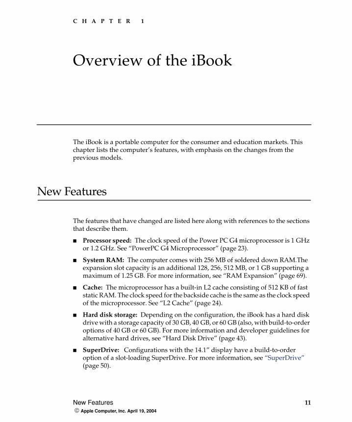
The iBook is a portable computer for the consumer and education markets. This chapter lists the computer’s features, with emphasis on the changes from the previous models.
New Features
The features that have changed are listed here along with references to the sections that describe them.
�
Processor speed:
The clock speed of the Power PC G4 microprocessor is 1 GHz or 1.2 GHz. See “PowerPC G4 Microprocessor” (page 23).
�
System RAM:
The computer comes with 256 MB of soldered down RAM.The expansion slot capacity is an additional 128, 256, 512 MB, or 1 GB supporting a maximum of 1.25 GB. For more information, see “RAM Expansion” (page 69).
�
Cache:
The microprocessor has a built-in L2 cache consisting of 512 KB of fast static RAM. The clock speed for the backside cache is the same as the clock speed of the microprocessor. See “L2 Cache” (page 24).
�
Hard disk storage:
Depending on the configuration, the iBook has a hard disk drive with a storage capacity of 30 GB, 40 GB, or 60 GB (also, with build-to-order options of 40 GB or 60 GB). For more information and developer guidelines for alternative hard drives, see “Hard Disk Drive” (page 43).
�
SuperDrive:
Configurations with the 14.1” display have a build-to-order option of a slot-loading SuperDrive. For more information, see “SuperDrive” (page 50).
12
All Features
Apple Computer, Inc. April 19, 2004
C H A P T E R 1
Overview of the iBook
�
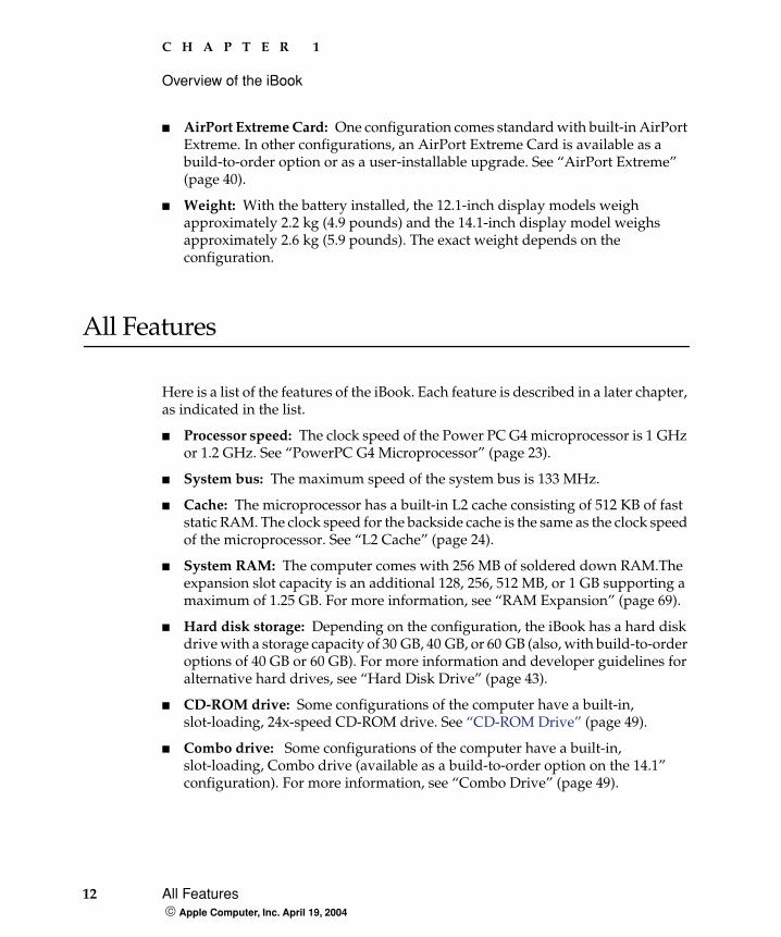
AirPort Extreme Card:
One configuration comes standard with built-in AirPort Extreme. In other configurations, an AirPort Extreme Card is available as a build-to-order option or as a user-installable upgrade. See “AirPort Extreme” (page 40).
�
Weight:
With the battery installed, the 12.1-inch display models weigh approximately 2.2 kg (4.9 pounds) and the 14.1-inch display model weighs approximately 2.6 kg (5.9 pounds). The exact weight depends on the configuration.
All Features
Here is a list of the features of the iBook. Each feature is described in a later chapter, as indicated in the list.
�
Processor speed:
The clock speed of the Power PC G4 microprocessor is 1 GHz or 1.2 GHz. See “PowerPC G4 Microprocessor” (page 23).
�
System bus:
The maximum speed of the system bus is 133 MHz.
�
Cache:
The microprocessor has a built-in L2 cache consisting of 512 KB of fast static RAM. The clock speed for the backside cache is the same as the clock speed of the microprocessor. See “L2 Cache” (page 24).
�
System RAM:
The computer comes with 256 MB of soldered down RAM.The expansion slot capacity is an additional 128, 256, 512 MB, or 1 GB supporting a maximum of 1.25 GB. For more information, see “RAM Expansion” (page 69).
�
Hard disk storage:
Depending on the configuration, the iBook has a hard disk drive with a storage capacity of 30 GB, 40 GB, or 60 GB (also, with build-to-order options of 40 GB or 60 GB). For more information and developer guidelines for alternative hard drives, see “Hard Disk Drive” (page 43).
�
CD-ROM drive:
Some configurations of the computer have a built-in, slot-loading, 24x-speed CD-ROM drive. See “CD-ROM Drive” (page 49).
�
Combo drive:
Some configurations of the computer have a built-in, slot-loading, Combo drive (available as a build-to-order option on the 14.1” configuration). For more information, see “Combo Drive” (page 49).
C H A P T E R 1
Overview of the iBook
All Features
13
Apple Computer, Inc. April 19, 2004
�
SuperDrive:
Configurations with the 14.1” display have a build-to-order option of a slot-loading SuperDrive. For more information, see “SuperDrive” (page 50).
�
Display:
Two TFT display sizes are available: a 12.1-inch and a 14.1-inch. Both displays have XGA (1024x768) resolution. See “Flat Panel Display” (page 61).
�
External display connector:
The external display connector supports VGA, composite, and S-video formats for devices such as monitors and projectors. See “External Display Port” (page 62).
�
Graphics IC:
The display controller is an ATI Mobility Radeon 9200 with 32 MB of graphics DDR SDRAM. See “Graphics IC” (page 26).
�
Microphone:
The computer has a built-in microphone. See “Sound System” (page 65).
�
Battery:
The computer has one battery bay. The 50 watt-hour battery in the 12.1-inch display models uses six lithium ion cells and provides up to 6 hours of operation, depending on configuration and usage. The 61 watt-hour battery in the 14.1-inch display model uses eight lithium ion cells and provides up to 6 hours of operation, depending on configuration and usage.
�
USB 2.0 ports:
The computer has two external USB 2.0 ports. See “USB Ports” (page 33).
�
FireWire 400 port:
The computer has an IEEE-1394a FireWire 400 high-speed serial port. See “FireWire 400 Port” (page 35).
�
Target disk mode:
The computer can act like a FireWire storage device connected to another computer. See “Target Disk Mode” (page 20).
�
Modem:
The computer has a built-in modem that supports 56 Kbps data rate with V.92 modem standards. See “Internal Modem” (page 39).
�
Ethernet:
The computer has a built in Ethernet port for 10Base-T and 100Base-T operation. See “Ethernet Port” (page 38).
�
AirPort Extreme Card:
One configuration comes standard with built-in AirPort Extreme. In other configurations, an AirPort Extreme Card is available as a build-to-order option or as a user-installable upgrade. See “AirPort Extreme” (page 40).
�
Bluetooth:
One configuration comes standard with built-in Bluetooth. In other configurations, Bluetooth is available as a build-to-order option. For more information, see “Bluetooth Technology” (page 42).
14
Appearance
Apple Computer, Inc. April 19, 2004
C H A P T E R 1
Overview of the iBook
�
Sound:
The computer has a built-in microphone and stereo speakers; it provides stereo output signals on the audio minijack. See “Sound System” (page 65).
�
Keyboard:
The keyboard has function keys and inverted-T arrow keys. Some of the function keys are used to control the brightness and sound and to eject a disk. The keyboard also includes an embedded numeric keypad. See “Keyboard” (page 52).
� Trackpad: The integrated trackpad includes tap/double tap and drag features. See “Trackpad” (page 51).
� Weight: With the battery installed, the 12.1-inch display models weigh approximately 2.2 kg (5 pounds) and the 14-1-inch display model weighs approximately 2.6 kg (6 pounds). The exact weight depends on the configuration.
� Size: The 12.1-inch display models are 28.50 cm (11.2 inches) wide,depth 23.03 cm (9.06 inches) deep, and 3.42 cm (1.35 inches) thick. The 14.1-inch display model is 32.3 cm (12.7 inches) wide, 25.8 cm (10.2 inches) deep, and 3.42 cm (1.35 inches) thick.
� Security slot: The iBook has a slot for attaching a Kensington security cable.
Appearance
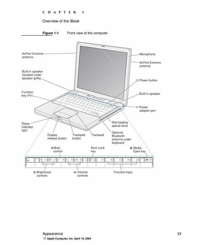
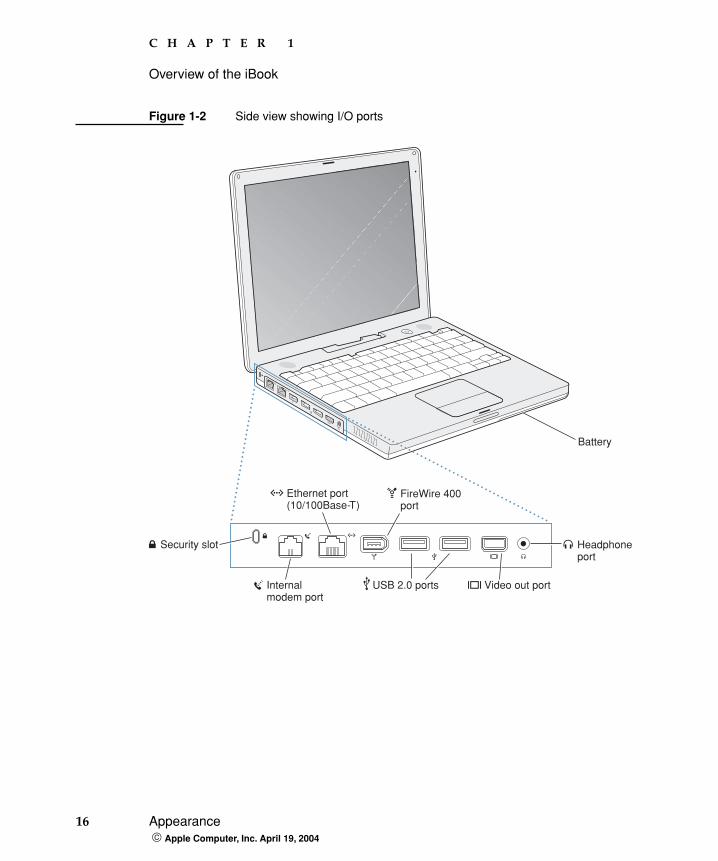
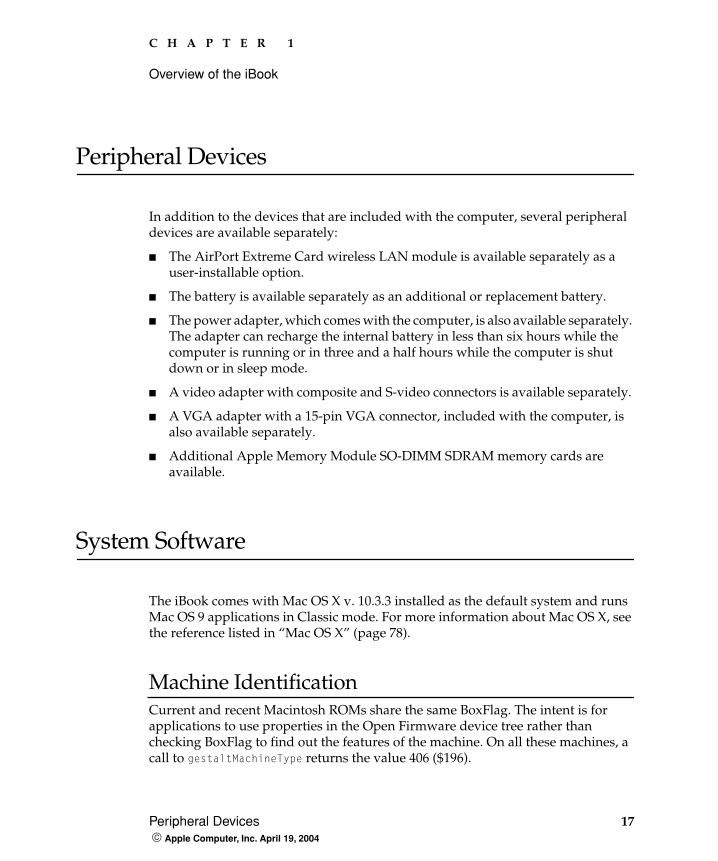
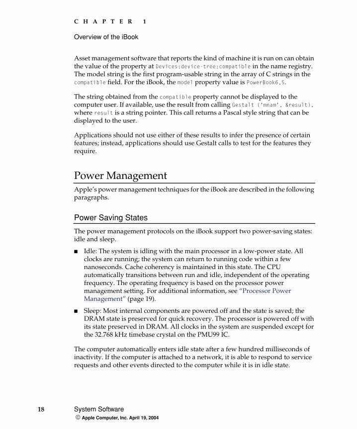
Figure 1-1 is a front view of the iBook; Figure 1-2 (page 16) provides a side view showing the I/O ports.
C H A P T E R 1
Overview of the iBook
Appearance 15 Apple Computer, Inc. April 19, 2004
Figure 1-1 Front view of the computer
Built-in speaker
Power button
AirPort Extremeantenna
AirPort Extremeantenna
Microphone
Functionkey (Fn)
Sleepindicatorlight
TrackpadDisplayrelease button
Trackpadbutton
Slot-loadingoptical drive
OptionalBluetoothantenna underkeyboard
Volumecontrols
Brightnesscontrols
Num Lockkey
Function keys
Mutecontrol
MediaEject key
Poweradapter port
Built-in speaker(located underspeaker grille)
16 Appearance Apple Computer, Inc. April 19, 2004
C H A P T E R 1
Overview of the iBook
Figure 1-2 Side view showing I/O ports
Internalmodem port
Headphoneport
Battery
Ethernet port(10/100Base-T)
USB 2.0 ports
FireWire 400port
Video out port
Security slot
C H A P T E R 1
Overview of the iBook
Peripheral Devices 17 Apple Computer, Inc. April 19, 2004
Peripheral Devices
In addition to the devices that are included with the computer, several peripheral devices are available separately:
� The AirPort Extreme Card wireless LAN module is available separately as a user-installable option.
� The battery is available separately as an additional or replacement battery.
� The power adapter, which comes with the computer, is also available separately. The adapter can recharge the internal battery in less than six hours while the computer is running or in three and a half hours while the computer is shut down or in sleep mode.
� A video adapter with composite and S-video connectors is available separately.
� A VGA adapter with a 15-pin VGA connector, included with the computer, is also available separately.
� Additional Apple Memory Module SO-DIMM SDRAM memory cards are available.
System Software
The iBook comes with Mac OS X v. 10.3.3 installed as the default system and runs Mac OS 9 applications in Classic mode. For more information about Mac OS X, see the reference listed in “Mac OS X” (page 78).
Machine IdentificationCurrent and recent Macintosh ROMs share the same BoxFlag. The intent is for applications to use properties in the Open Firmware device tree rather than checking BoxFlag to find out the features of the machine. On all these machines, a call to gestaltMachineType returns the value 406 ($196).
18 System Software Apple Computer, Inc. April 19, 2004
C H A P T E R 1
Overview of the iBook
Asset management software that reports the kind of machine it is run on can obtain the value of the property at Devices:device-tree:compatible in the name registry. The model string is the first program-usable string in the array of C strings in the compatible field. For the iBook, the model property value is PowerBook6,5.
The string obtained from the compatible property cannot be displayed to the computer user. If available, use the result from calling Gestalt ('mnam', &result), where result is a string pointer. This call returns a Pascal style string that can be displayed to the user.
Applications should not use either of these results to infer the presence of certain features; instead, applications should use Gestalt calls to test for the features they require.
Power ManagementApple’s power management techniques for the iBook are described in the following paragraphs.
Power Saving States
The power management protocols on the iBook support two power-saving states: idle and sleep.
� Idle: The system is idling with the main processor in a low-power state. All clocks are running; the system can return to running code within a few nanoseconds. Cache coherency is maintained in this state. The CPU automatically transitions between run and idle, independent of the operating frequency. The operating frequency is based on the processor power management setting. For additional information, see “Processor Power Management” (page 19).
� Sleep: Most internal components are powered off and the state is saved; the DRAM state is preserved for quick recovery. The processor is powered off with its state preserved in DRAM. All clocks in the system are suspended except for the 32.768 kHz timebase crystal on the PMU99 IC.
The computer automatically enters idle state after a few hundred milliseconds of inactivity. If the computer is attached to a network, it is able to respond to service requests and other events directed to the computer while it is in idle state.
C H A P T E R 1
Overview of the iBook
System Software 19 Apple Computer, Inc. April 19, 2004
While it is connected to an AC power supply, the computer can also respond to network activity when it is in sleep state. The user can enable this feature by selecting Wake-on-LAN in the Energy Saver preference pane.
When operating on the battery in sleep state, the computer consumes less than 1 watt of power, meeting the Energy Star power-saving standard. When operating on the power adapter in sleep state, the combined computer and adapter consume 3 to 4 watts of power.
Processor Power Management
To lower power consumption and heat generation, the iBook incorporates an automatic power management technique called dynamic frequency switching (DFS). DFS is designed to run at high processor speed and voltage when the demand on the processor is high, and to run at low processor speed and voltage when the demand on the processor is low. Switching between different processor speeds and voltages is achieved by a transition that operates seamlessly to the user and should not impact system or application performance.
The iBook allows the user to control DFS mode. The options for specifying either high, reduced, or automatic processor and bus speeds are located at System Preferences>Energy Saver>Show Details>Options>Processor Performance; then select Highest, Automatic, or Reduced.
DFS is enabled with the automatic setting; DFS also operates in the low setting.
If the iBook detects a system temperature that is high, due to high ambient temperatures or other factors, it will automatically force the system to reduced speed mode regardless of the selected setting.
When DFS is enabled, the processor dynamically adjusts its speed based on the current needs of the system. The processor speed will switch between 1000 MHz and 500 MHz or between 1200 MHz and 600 MHz, depending on the configuration.
Note: The memory bus speed is not shifted, as it was in previous models.
20 System Software Apple Computer, Inc. April 19, 2004
C H A P T E R 1
Overview of the iBook
Target Disk Mode The user has the option at boot time to put the iBook into a mode of operation called target disk mode (TDM). When the iBook is in target disk mode and connected to another Macintosh computer by a FireWire cable, the iBook operates like a FireWire mass storage device with the SBP-2 (Serial Bus Protocol) standard. Target disk mode has two primary uses:
� data transfer between computers
� diagnosis and repair of a corrupted internal hard drive
The iBook can operate in target disk mode as long as the other computer has a FireWire port and either Mac OS X (any version) or Mac OS 9 with FireWire software version 2.3.3 or later.
To put the iBook into target disk mode, restart the computer and hold down the T key until the FireWire icon appears on the display. Then connect a FireWire cable from the iBook to the other computer. When the other computer completes the FireWire connection, a hard disk icon appears on its desktop.
If the iBook is turned off or the FireWire cable is disconnected while in target disk mode, an alert appears on the other computer. Disconnecting while the disk is in use can cause loss of data on the target disk.
To dismount the iBook out of target disk mode, drag the hard disk icon of the targeted computer to the trash on the main computer. When the computer is fully dismounted, press the power button on the targeted computer.
Note: When serving as host in target disk mode, the iBook runs at reduced bus speed, as described in “Processor Power Management” (page 19).
Block Diagram and Buses 21 Apple Computer, Inc. April 19, 2004
C H A P T E R 2
2 Architecture
This chapter describes the architecture of the iBook.
Block Diagram and Buses
This section is an overview of the major ICs and buses on the computer’s main logic board.
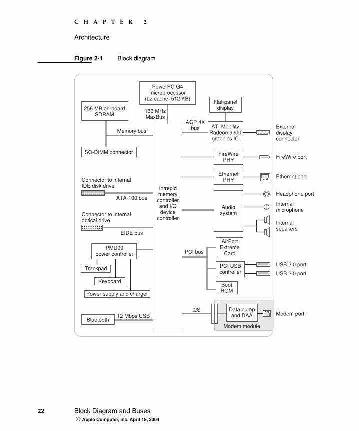
Block DiagramFigure 2-1 is a simplified block diagram of the main logic board. The diagram shows the input and output connectors, the main ICs, and the buses that connect them together.
22 Block Diagram and Buses Apple Computer, Inc. April 19, 2004
C H A P T E R 2
Architecture
Figure 2-1 Block diagram
Externaldisplayconnector
Ethernet port
FireWire port
Internalspeakers
Headphone port
Internalmicrophone
AGP 4XbusMemory bus
133 MHzMaxBus
PMU99power controller
Trackpad
Keyboard
Power supply and charger
SO-DIMM connector
ATI MobilityRadeon 9200graphics IC
Flat-paneldisplay
Audiosystem
EthernetPHY
FireWirePHY
PowerPC G4microprocessor
(L2 cache: 512 KB)
256 MB on-boardSDRAM
PCI bus
BootROM
USB 2.0 port
USB 2.0 portPCI USBcontroller
AirPortExtreme
Card
ATA-100 bus
EIDE bus
Connector to internalIDE disk drive
Connector to internaloptical drive
I2S12 Mbps USB Modem port
Modem moduleBluetooth
Data pumpand DAA
Intrepidmemorycontrollerand I/Odevice
controller
C H A P T E R 2
Architecture
Microprocessor and Cache 23 Apple Computer, Inc. April 19, 2004
Main ICs and BusesThe architecture of the iBook is designed around the PowerPC G4 microprocessor and the Intrepid IC, which provides the functions of a memory controller and an I/O device controller.
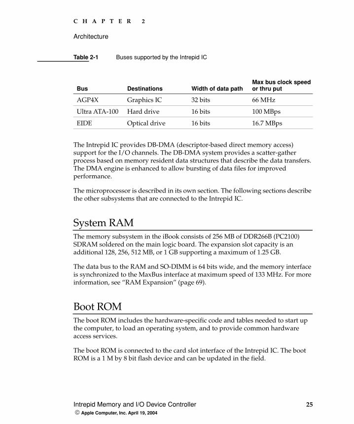
The PowerPC G4 microprocessor is connected to the Intrepid IC by a MaxBus. The maximum bus clock speed is 133 MHz. Additional buses implemented by the Intrepid IC are summarized in Table 2-1 (page 24).
The Intrepid IC has a 32-bit PCI bus with a bus clock speed of 33 MHz. The PCI bus also connects to the Boot ROM and the wireless LAN module. The Intrepid IC has other buses that connect with the hard disk drive, the optical drive, the power controller IC, the sound IC, and the internal modem module.
Each of the components listed here is described in one of the following sections.
Microprocessor and Cache
The microprocessor communicates with the rest of the system by way of a 64-bit MaxBus bus to the Intrepid IC. The microprocessor has a separate bus to its internal second-level cache.
PowerPC G4 MicroprocessorThe PowerPC G4 microprocessor used in the iBook has many powerful features, including an efficient pipelined system bus called MaxBus.
Features of the PowerPC G4 include
� 32-bit PowerPC implementation
� superscalar PowerPC core
� Velocity Engine (AltiVec technology): 128-bit-wide vector execution unit
� dual 32 KB instruction and data caches
� an on-chip level 2 (L2) cache consisting of 512 KB with a clock speed ratio of 1:1
24 Intrepid Memory and I/O Device Controller Apple Computer, Inc. April 19, 2004
C H A P T E R 2
Architecture
� high bandwidth MaxBus (also compatible with 60x bus)
� fully symmetric multiprocessing capability
The PowerPC G4 microprocessor in the iBook runs at a maximum clock speed of 1 GHz or 1.2 GHz.
L2 CacheThe data storage for the L2 cache consists of 512 KB of fast static RAM that is built into the microprocessor chip along with the cache controller and tag storage. The built-in L2 cache runs at the same clock speed as the microprocessor.
Intrepid Memory and I/O Device Controller
The Intrepid memory and I/O device controller IC provides cost and performance benefits by combining many functions into a single IC. It also contains the PCI bus bridge, the Ethernet, FireWire, and USB interfaces, and the AGP port.
In addition to the buses listed in Table 2-1, the Intrepid IC has separate interfaces to the physical layer (PHY) ICs for Ethernet and FireWire. Also, Intrepid has an I2C interface to configure the memory subsystem and an OHCI USB controller to connect the internal modem and Bluetooth modules.
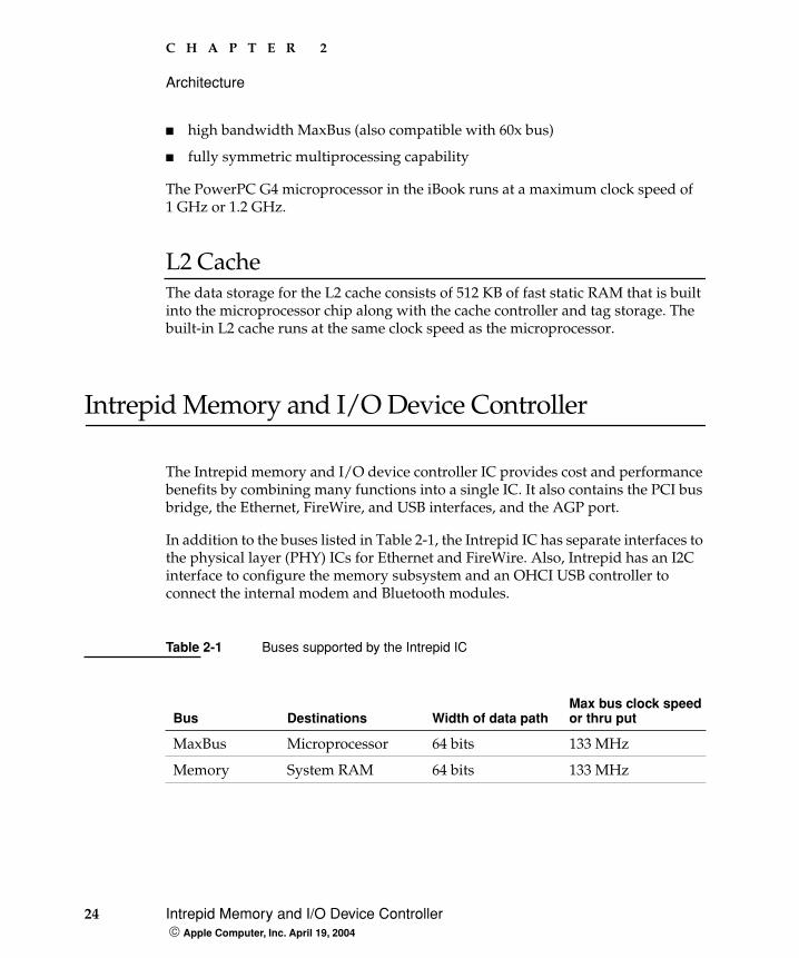
Table 2-1 Buses supported by the Intrepid IC
Bus Destinations Width of data pathMax bus clock speedor thru put
MaxBus Microprocessor 64 bits 133 MHz
Memory System RAM 64 bits 133 MHz
C H A P T E R 2
Architecture
Intrepid Memory and I/O Device Controller 25 Apple Computer, Inc. April 19, 2004
The Intrepid IC provides DB-DMA (descriptor-based direct memory access) support for the I/O channels. The DB-DMA system provides a scatter-gather process based on memory resident data structures that describe the data transfers. The DMA engine is enhanced to allow bursting of data files for improved performance.
The microprocessor is described in its own section. The following sections describe the other subsystems that are connected to the Intrepid IC.
System RAMThe memory subsystem in the iBook consists of 256 MB of DDR266B (PC2100) SDRAM soldered on the main logic board. The expansion slot capacity is an additional 128, 256, 512 MB, or 1 GB supporting a maximum of 1.25 GB.
The data bus to the RAM and SO-DIMM is 64 bits wide, and the memory interface is synchronized to the MaxBus interface at maximum speed of 133 MHz. For more information, see “RAM Expansion” (page 69).
Boot ROMThe boot ROM includes the hardware-specific code and tables needed to start up the computer, to load an operating system, and to provide common hardware access services.
The boot ROM is connected to the card slot interface of the Intrepid IC. The boot ROM is a 1 M by 8 bit flash device and can be updated in the field.
AGP4X Graphics IC 32 bits 66 MHz
Ultra ATA-100 Hard drive 16 bits 100 MBps
EIDE Optical drive 16 bits 16.7 MBps
Table 2-1 Buses supported by the Intrepid IC
Bus Destinations Width of data pathMax bus clock speedor thru put
26 Intrepid Memory and I/O Device Controller Apple Computer, Inc. April 19, 2004
C H A P T E R 2
Architecture
Ethernet Controller The Intrepid IC includes an Ethernet media access controller (MAC) that implements the link layer. As a separate channel connected directly to the Intrepid logic, it can operate at its full capacity without degrading the performance of other peripheral devices.
The controller is connected to a PHY interface IC that is capable of operating in either 10-BaseT or 100-BaseT mode. The actual speed of the link is automatically negotiated by the PHY and the bridge or router to which it is connected. For information about the connector and the operation of the port, see “Ethernet Port” (page 38).
FireWire 400 ControllerThe Intrepid IC includes an IEEE 1394a FireWire 400 controller with a maximum data rate of 400 Mbits (50 MBytes) per second. The Intrepid IC provides DMA (direct memory access) support for the FireWire400 interface. The FireWire controller complies with the Open Host Controller Interface (OHCI) specification.
The controller IC implements the FireWire link layer. A physical layer IC, called a PHY, implements the electrical signalling protocol of the FireWire interface. The PHY is the interface to the external connector. For information about the connector and the operation of the port, see “FireWire 400 Port” (page 35).
Graphics IC The graphics IC is an ATI Mobility Radeon 9200 with 32 MB video memory. It provides video for both the internal flat panel display and an external video display. The signals to the external display can be either VGA, composite video, or S-video; for more information, see“External Display Port” (page 62).
The signal generated for the flat panel display is simultaneously available for an external display. The external display mirrors the built-in display. For more information, see “External Display Port” (page 62).
The graphics IC supports a display size of 1024x768 pixels and also has a scaling mode that displays a 640x480 or 800x600 pixel image on the full screen.

C H A P T E R 2
Architecture
Intrepid Memory and I/O Device Controller 27 Apple Computer, Inc. April 19, 2004
The ATI Mobility Radeon 9200 IC also has a 3D graphics engine for fast rendering of 3D objects.
Because the graphics IC uses the AGP bus, it can use part of main memory as additional graphics storage. The computer’s virtual memory system organizes main memory as randomly-distributed 4 KB pages, so DMA transactions for more than 4 KB of data would have to perform scatter-gather operations. The AGP logic in the Intrepid IC uses a graphics address remapping table (GART) to translate a linear address space for AGP transactions into physical addresses in main memory.
DMA SupportThe Intrepid IC provides DB-DMA (descriptor-based direct memory access) support for the following I/O channels:
� Ultra DMA ATA interface to the internal hard drive
� IIS channel to the sound IC
The DB-DMA system provides a scatter-gather process based on memory resident data structures that describe the data transfers. The DMA engine is enhanced to allow bursting of data files for improved performance.
Interrupt SupportThe Intrepid IC has an interrupt controller (MPIC) that handles interrupts generated within the IC as well as external interrupts, such as those from the Ethernet and FireWire controllers.
ATA-100 Interface The Intrepid IC provides an Ultra DMA ATA-100 channel that is connected to the internal hard disk drive. The Intrepid IC provides DB-DMA (descriptor-based direct memory access) support for the Ultra DMA interface.
The internal hard disk drive is connected as device 0 (master) in an ATA Device 0/1 configuration.
28 Intrepid Memory and I/O Device Controller Apple Computer, Inc. April 19, 2004
C H A P T E R 2
Architecture
EIDE InterfaceThe Intrepid IC provides an EIDE interface that supports the optical drive. The optical drive is an ATAPI drive and is device-selected as master in an ATA device configuration.
USB 1.1 ControllersThe external USB interface is via the PCI USB controller; see “PCI USB 2.0 Controller” (page 30).
The Intrepid IC has three independent USB 1.1 host controllers each with a maximum data rate of 12 Mbps. The controllers comply with USB Open Host Controller Interface (OHCI).
In the iBook, only one of the Intrepid USB host controllers is used for the Bluetooth adapter. The other host controllers are disabled for power savings reasons.
Modem Support The internal modem is connected to an internal I2S port. The internal modem is a separate module that contains the datapump IC and the interface to the telephone line (DAA). The controller functions are performed by the main processor. See “Internal Modem” (page 39).
Sound Circuitry The iBook has sound circuitry that is connected to the Intrepid IC by a standard I2S bus. The Intrepid IC provides DB-DMA (descriptor-based direct memory access) support for the I2S port.
The sound circuitry includes a signal processing IC that handles the equalization and volume control functions and a codec IC that performs A-to-D and D-to-A conversion.
All audio is handled digitally inside the computer. The sound circuitry performs digital-to-analog conversion for the audio signals to the internal speakers and the headphone mini-jack. The sound circuitry also provides parametric equalization for the internal speakers.
C H A P T E R 2
Architecture
Intrepid Memory and I/O Device Controller 29 Apple Computer, Inc. April 19, 2004
Modem progress audio is connected as a digital input to the sound circuitry so that it can be mixed into the sound output stream. The modem progress audio is processed as play-through only, not as a digital sound source.
The iBook has no dedicated sound input jack. The sound system supports the built-in microphone and other sound input by way of a USB microphone or other USB audio device. For information about sound system operation, see “Sound System” (page 65).
Power Control IC The power manager IC in the iBook is a Mitsubishi M16C/62F microprocessor, also called the PMU99. It operates with its own RAM and ROM. The functions of the PMU99 include:
� controlling the sleep and power on and off sequences
� controlling power to the other ICs
� monitoring the battery charge level
� controlling battery charging
� supporting the interface to the built-in keyboard and trackpad
� keeping track of real time clock operations, including date and time
The iBook can operate from a 15-volt power outlet on an airliner, however for safety reasons the computer will not allow battery charging. In order for the computer to detect the connection to airline power, the airline power cable (available separately) should have a sense resistor of 24.3K ohms connected between the power plug's shell and ground.
The PMU99 also provides the hardware interface to the keyboard and trackpad. Software in the PMU99 IC scans the keyboard and receives data from the trackpad, then sends the data to the system in packets like those from the ADB. To the system, the keyboard and trackpad behave as if they were ADB devices.
30 AirPort Extreme Interface Apple Computer, Inc. April 19, 2004
C H A P T E R 2
Architecture
AirPort Extreme Interface
AirPort Extreme contains a media access controller (MAC), a digital signal processor (DSP), and a radio-frequency (RF) section.
Two antennas are built into the computer’s case. To improve reception, a diversity module between the antennas and the card measures the signal strength from both antennas and selects the stronger signal for AirPort Extreme.
AirPort Extreme is compliant with the IEEE 802.11g standard. The card transmits and receives data at up to 54 Mbps and is compatible with 802.11b-standard 11 Mbps systems and older 802.11b-standard systems. For information about its operation, see “AirPort Extreme” (page 40).
PCI USB 2.0 Controller
The iBook CPU uses a PCI USB controller with one Enhanced Host Controller Interface (EHCI) function and two Open Host Controller Interface (OHCI) functions. The controller supports two external USB 2.0 ports.
The two external USB ports comply with the Universal Serial Bus Specification 2.0. The USB register set complies with the EHCI and OHCI specifications. For more information, see “USB Ports” (page 33).
The two external USB 2.0 connectors support USB devices with data transfer rates of up to 480 Mbps. For more information about the connectors, see “USB Connector” (page 33).
All USB devices connected to the iBook are required to support USB-suspend mode as defined in the USB specification. For additional reference information, see “USB Interface” (page 81).
C H A P T E R 2
Architecture
PCI USB 2.0 Controller 31 Apple Computer, Inc. April 19, 2004
The USB ports on the iBook comply with the Universal Serial Bus Specification 2.0. The USB controllers comply with the EHCI specification; the companion controllers comply with the OHCI specification.
For information on the Intrepid USB 1.1 interface, see “USB 1.1 Controllers” (page 28).

32 PCI USB 2.0 Controller Apple Computer, Inc. April 19, 2004
C H A P T E R 2
Architecture
USB Ports 33 Apple Computer, Inc. April 19, 2004
C H A P T E R 3
3 Devices and Ports
This chapter describes both the built-in I/O devices and the ports for connecting external I/O devices. Each of the following sections describes an I/O port or device.
USB Ports
The iBook has two external USB 2.0 ports that can be used to connect additional I/O devices such as a USB mouse, printers, scanners, and storage devices.
The USB ports on the iBook comply with the Universal Serial Bus Specification 2.0. For more information about USB on Macintosh computers, consult the references at “USB Interface” (page 81).
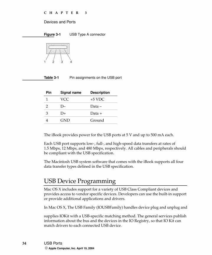
USB ConnectorThe USB port uses a USB Type A connector, which has four pins. Two of the pins are used for power and two for data. Figure 3-1 is an illustration of a Type A USB port. Table 3-1 shows the pin assignments.
Note: Some self-powered USB devices inadvertantly violate electrical specifications for self-powered USB devices. For details and ways to avoid this design issue, refer to http://developer.apple.com/qa/hw/hw82.html.
34 USB Ports Apple Computer, Inc. April 19, 2004
C H A P T E R 3
Devices and Ports
Figure 3-1 USB Type A connector
The iBook provides power for the USB ports at 5 V and up to 500 mA each.
Each USB port supports low-, full-, and high-speed data transfers at rates of 1.5 Mbps, 12 Mbps, and 480 Mbps, respectively. All cables and peripherals should be compliant with the USB specification.
The Macintosh USB system software that comes with the iBook supports all four data transfer types defined in the USB specification.
USB Device ProgrammingMac OS X includes support for a variety of USB Class Compliant devices and provides access to vendor specific devices. Developers can use the built-in support or provide additional applications and drivers.
In Mac OS X, The USB Family (IOUSBFamily) handles device plug and unplug and
supplies IOKit with a USB-specific matching method. The general services publish information about the bus and the devices in the IO Registry, so that IO Kit can match drivers to each connected USB device.
Table 3-1 Pin assignments on the USB port
Pin Signal name Description
1 VCC +5 VDC
2 D– Data –
3 D+ Data +
4 GND Ground
1 32 4
C H A P T E R 3
Devices and Ports
FireWire 400 Port 35 Apple Computer, Inc. April 19, 2004
In the iBook, Mac OS X provides the following USB class compliant drivers:
� Audio
� Bluetooth
� CDC (Communication Data Class)
� modem (abstract control model only)
� HID (Human Interface Device)
� boot protocol
� report protocol
� HUB
� Mass storage
� MIDI
� Printer
� Still image/PTP (digital still cameras)
For information on writing USB drivers or applications, download the latest USB SDK from http://developer.apple.com/sdk/.
For information about USB support on the Macintosh, see the references in “USB Interface” (page 81).
FireWire 400 Port
The iBook has one external FireWire 400 IEEE 1394a port. The FireWire 400 port
� supports serial I/O at 100, 200, and 400 Mbps (megabits per second)
� provides up to 7 watts of peak power when the computer system is on or the power adapter is connected
� supports booting the system from a mass storage device
� supports target disk mode (TDM)
36 FireWire 400 Port Apple Computer, Inc. April 19, 2004
C H A P T E R 3
Devices and Ports
The FireWire 400 hardware and software provided with the iBook are capable of all asynchronous and isochronous transfers defined by IEEE standard 1394.
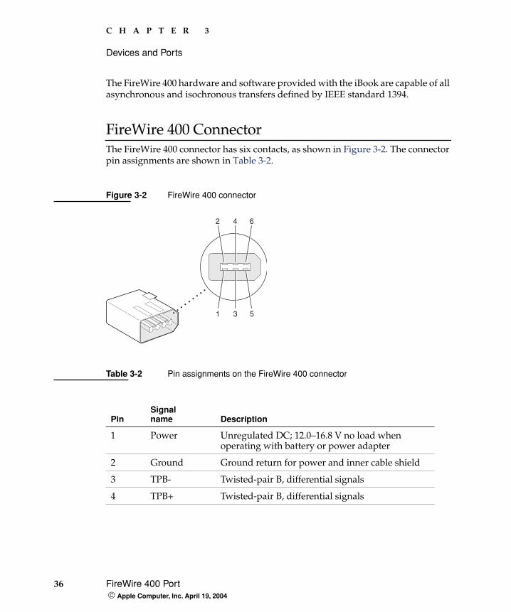
FireWire 400 ConnectorThe FireWire 400 connector has six contacts, as shown in Figure 3-2. The connector pin assignments are shown in Table 3-2.
Figure 3-2 FireWire 400 connector
Table 3-2 Pin assignments on the FireWire 400 connector
PinSignal name Description
1 Power Unregulated DC; 12.0–16.8 V no load when operating with battery or power adapter
2 Ground Ground return for power and inner cable shield
3 TPB- Twisted-pair B, differential signals
4 TPB+ Twisted-pair B, differential signals
1 3 5
2 4 6
C H A P T E R 3
Devices and Ports
FireWire 400 Port 37 Apple Computer, Inc. April 19, 2004
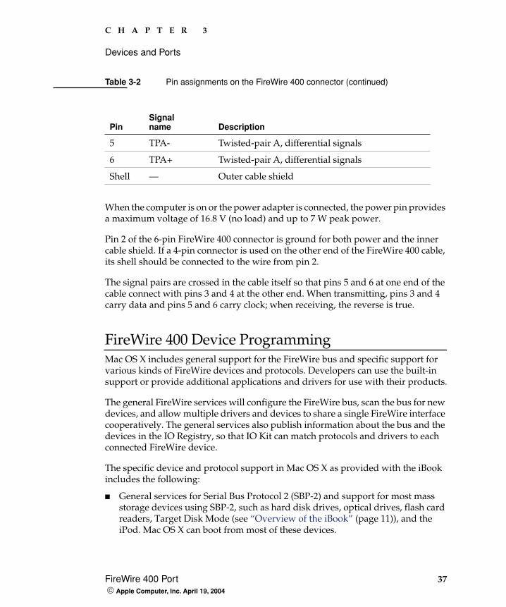
When the computer is on or the power adapter is connected, the power pin provides a maximum voltage of 16.8 V (no load) and up to 7 W peak power.
Pin 2 of the 6-pin FireWire 400 connector is ground for both power and the inner cable shield. If a 4-pin connector is used on the other end of the FireWire 400 cable, its shell should be connected to the wire from pin 2.
The signal pairs are crossed in the cable itself so that pins 5 and 6 at one end of the cable connect with pins 3 and 4 at the other end. When transmitting, pins 3 and 4 carry data and pins 5 and 6 carry clock; when receiving, the reverse is true.
FireWire 400 Device ProgrammingMac OS X includes general support for the FireWire bus and specific support for various kinds of FireWire devices and protocols. Developers can use the built-in support or provide additional applications and drivers for use with their products.
The general FireWire services will configure the FireWire bus, scan the bus for new devices, and allow multiple drivers and devices to share a single FireWire interface cooperatively. The general services also publish information about the bus and the devices in the IO Registry, so that IO Kit can match protocols and drivers to each connected FireWire device.
The specific device and protocol support in Mac OS X as provided with the iBook includes the following:
� General services for Serial Bus Protocol 2 (SBP-2) and support for most mass storage devices using SBP-2, such as hard disk drives, optical drives, flash card readers, Target Disk Mode (see “Overview of the iBook” (page 11)), and the iPod. Mac OS X can boot from most of these devices.
5 TPA- Twisted-pair A, differential signals
6 TPA+ Twisted-pair A, differential signals
Shell — Outer cable shield
Table 3-2 Pin assignments on the FireWire 400 connector (continued)
PinSignal name Description
38 Ethernet Port Apple Computer, Inc. April 19, 2004
C H A P T E R 3
Devices and Ports
� General services for the Audio Video Control (AV/C) protocol and support for most digital video (DV) cameras and decks using this protocol, including video capture through standard QuickTime APIs.
� A QuickTime device driver for IIDC/DCAM type cameras such as the iSight.
� A network device driver supporting IP (Internet Protocol) over FireWire according to IEEE RFC 2734.
� Additional services for user-space and kernel access to all FireWire resources.
For information on writing FireWire drivers or applications, download the latest FireWire SDK from http://developer.apple.com/sdk/.
For additional information about the FireWire 400 interface, refer to the resources listed in “FireWire 400 Interface” (page 81).
Ethernet Port
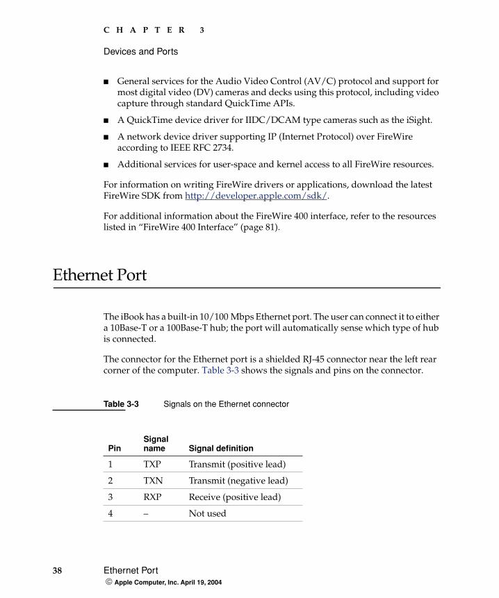
The iBook has a built-in 10/100 Mbps Ethernet port. The user can connect it to either a 10Base-T or a 100Base-T hub; the port will automatically sense which type of hub is connected.
The connector for the Ethernet port is a shielded RJ-45 connector near the left rear corner of the computer. Table 3-3 shows the signals and pins on the connector.
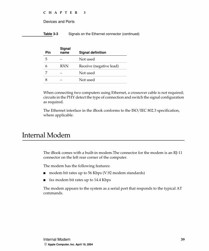
Table 3-3 Signals on the Ethernet connector
PinSignal name Signal definition
1 TXP Transmit (positive lead)
2 TXN Transmit (negative lead)
3 RXP Receive (positive lead)
4 – Not used
C H A P T E R 3
Devices and Ports
Internal Modem 39 Apple Computer, Inc. April 19, 2004
When connecting two computers using Ethernet, a crossover cable is not required; circuits in the PHY detect the type of connection and switch the signal configuration as required.
The Ethernet interface in the iBook conforms to the ISO/IEC 802.3 specification, where applicable.
Internal Modem
The iBook comes with a built-in modem.The connector for the modem is an RJ-11 connector on the left rear corner of the computer.
The modem has the following features:
� modem bit rates up to 56 Kbps (V.92 modem standards)
� fax modem bit rates up to 14.4 Kbps
The modem appears to the system as a serial port that responds to the typical AT commands.
5 – Not used
6 RXN Receive (negative lead)
7 – Not used
8 – Not used
Table 3-3 Signals on the Ethernet connector (continued)
PinSignal name Signal definition
40 AirPort Extreme Apple Computer, Inc. April 19, 2004
C H A P T E R 3
Devices and Ports
AirPort Extreme
The iBook computer supports the AirPort Extreme Card, an internal wireless LAN module that is compliant with the IEEE 802.11g standard. By communicating wirelessly with a base station, AirPort Extreme can be used for internet access, email access, and file exchange. A base station provides the connection to the Internet or the bridge between the wireless signals and a wired LAN or both. The AirPort Extreme Base Station has connectors for a wired LAN, a DSL or cable modem, or a standard telephone line using the optional 56K modem that is built-in on some models.
AirPort Extreme transmits and receives data at speeds up to 54 Mbps, comparable to wired networking speeds. Airport Extreme is also compatible with other devices that follow the IEEE 802.11b standard, including PC's. For more information about compatibility, see the reference at “Wireless Networks” (page 82).
AirPort Extreme is standard on one configuration of the iBook and is a build-to-order option on other configurations of the iBook.
Data SecurityAirPort Extreme has several features designed to maintain the security of the user’s data.
� In 802.11b mode, the system uses direct-sequence spread-spectrum (DSSS) technology that uses a multi-bit spreading code that effectively scrambles the data for any receiver that lacks the corresponding code.
� The system can use an Access Control List of authentic network client ID values (wireless and MAC addresses) to verify each client’s identity before granting access to the network.
Note: As is the case with the existing IEEE 802.11b standard, actual data throughput speeds will be lower than the indicated maximum connection speeds. Inherent in wireless LAN systems, bandwidth overhead is required for wireless routing, scrambling, security error correction, and other processes.
C H A P T E R 3
Devices and Ports
AirPort Extreme 41 Apple Computer, Inc. April 19, 2004
� When communicating with a base station, AirPort Extreme uses 64-bit and 128-bit WEP encryption to encode data while it is in transit. Additional security features may be available via firmware upgrades as 802.11 enhancements are ratified by IEEE.
� The AirPort Extreme Base Station can be configured to use NAT (Network Address Translation), protecting data from Internet hackers.
� The AirPort Extreme Base Station can authenticate users by their unique Ethernet IDs, preventing unauthorized computers from logging into your network. Network administrators can take advantage of RADIUS compatibility, used for authenticating users over a remote server. Smaller networks can offer the same security using a local look-up table located within the base station.
As an additional data security measure, VPN can be used in conjunction with the AirPort Extreme data security.
AirPort Extreme Hardware AirPort Extreme is a fully-integrated, wireless LAN module compliant with the IEEE 802.11g standard using both OFDM (orthogonal frequency-division multiplexing) and DSSS technologies. Using DSSS, AirPort Extreme is interoperable with PC-compatible wireless LANs that conform to the 802.11b standard at speeds of 11 Mbps, 5.5 Mbps, 2 Mbps, and 1 Mbps. Using OFDM, AirPort Extreme is compatible with all 802.11g standard speeds.
Two antennas are built into the computer, on either side of the flat-panel display. One antenna is always used for transmitting. Either of the two antennas may be used for receiving. Using a diversity technique, Air Port Extreme may select the antenna that gives the best reception.
AirPort Extreme Software The iBook includes software for setting up and using AirPort Extreme:
� AirPort Extreme Setup Assistant, an easy-to-use program that guides users through the steps necessary to set up AirPort Extreme or set up an AirPort Extreme Base Station.
� Users can switch between wireless networks and can create and join peer-to-peer networks. These functions are accessed via the AirPort Extreme status menu.
42 Bluetooth Technology Apple Computer, Inc. April 19, 2004
C H A P T E R 3
Devices and Ports
� AirPort Extreme Admin Utility, a utility for advanced users and system administrators. With it the user can edit the administrative and advanced settings needed for some advanced configurations.
Bluetooth Technology
Bluetooth is standard in the iBook. Bluetooth is an open specification that enables short-range wireless connections between desktop and laptop computers and a host of other peripheral devices. Bluetooth support is built into Mac OS X and compliant with Bluetooth specification v1.1. It operates on a globally available 2.4 GHz frequency band (ISM band) for worldwide compatibility and has a maximum throughput of 1Mbps.
The Bluetooth technology supports the following profiles:
� synchronization —enables synchronization of devices over Bluetooth
� serial —provides a wireless serial connection to other Bluetooth devices
� dial-up networking (DUN) — enables a mobile phone to act as a modem
� object push —enables the transfer of files between Bluetooth devices
� human interface device (HID) — enables the use of Bluetooth input devices (keyboards and mice)
� Bluetooth file transfer profile (FTP) — enables browsing of the file system of other Bluetooth devices which support Bluetooth FTP.
� hardcopy cable replacement profiler (HCRP) — defines functionality that enables a Bluetooth link to replace a printer cable, allowing standard Bluetooth drivers to be adapted to use Bluetooth links.
When Bluetooth is added as a build-to-order option, it is installed by Apple at the time of purchase as a fully integrated module. Accessing the Bluetooth capabilities without purchasing the integrated module will require a third-party dongle.
Note: Currently, Apple’s Bluetooth Update Version 1.5 supports only printing.

C H A P T E R 3
Devices and Ports
Hard Disk Drive 43 Apple Computer, Inc. April 19, 2004
When the Bluetooth option is installed, the Bluetooth antenna is located under the lower right side of the keyboard.
For more information on Bluetooth technology, refer to “Bluetooth” (page 82).
Hard Disk Drive
Depending on the configuration, the storage capacity of the internal hard disk drive is 30 GB, 40 GB, or 60 GB. Also, in some configurations, a 40 GB or 60 GB drive is available as a build-to-order option. The drive uses the Ultra ATA-100 (IDE, integrated drive electronics) interface and is ATA-6 compatible. Data Transfer Mode for the drive is ATA-100.
The software that supports the internal hard disk is similar to that in previous models with internal IDE drives and includes DMA support. For the information about that software, see the references in “ATA Devices” (page 80).
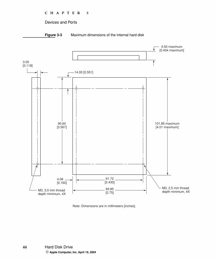
Hard Disk Dimensions Figure 3-3 shows the maximum dimensions of the hard disk and the location of the mounting holes. The minimum clearance between any conductive components on the drive and the bottom of the mounting envelope is 0.5 mm.
44 Hard Disk Drive Apple Computer, Inc. April 19, 2004
C H A P T E R 3
Devices and Ports
Figure 3-3 Maximum dimensions of the internal hard disk
3.00[0.118]
4.06[0.160]
61.72[2.430]
69.85[2.75]
M3, 2.5 mm threaddepth minimum, 4X
Note: Dimensions are in millimeters [inches].
9.50 maximum[0.404 maximum]
101.85 maximum[4.01 maximum]
90.60[3.567]
14.00 [0.551]
M3, 3.0 mm threaddepth minimum, 4X
C H A P T E R 3
Devices and Ports
Hard Disk Drive 45 Apple Computer, Inc. April 19, 2004
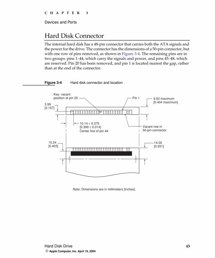
Hard Disk Connector The internal hard disk has a 48-pin connector that carries both the ATA signals and the power for the drive. The connector has the dimensions of a 50-pin connector, but with one row of pins removed, as shown in Figure 3-4. The remaining pins are in two groups: pins 1–44, which carry the signals and power, and pins 45–48, which are reserved. Pin 20 has been removed, and pin 1 is located nearest the gap, rather than at the end of the connector.
Figure 3-4 Hard disk connector and location
Note: Dimensions are in millimeters [inches].
3.99[0.157]
10.14 ± 0.375[0.399 ± 0.014]
Key: vacantposition at pin 20
Vacant row in50-pin connector
Pin 1
Center line of pin 44
10.24[0.403]
14.00[0.551]
9.50 maximum[0.404 maximum]
46 Hard Disk Drive Apple Computer, Inc. April 19, 2004
C H A P T E R 3
Devices and Ports
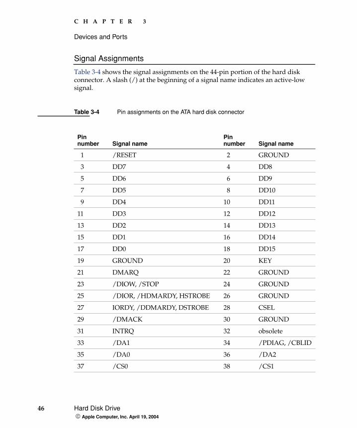
Signal Assignments
Table 3-4 shows the signal assignments on the 44-pin portion of the hard disk connector. A slash (/) at the beginning of a signal name indicates an active-low signal.
Table 3-4 Pin assignments on the ATA hard disk connector
Pin number Signal name
Pin number Signal name
1 /RESET 2 GROUND
3 DD7 4 DD8
5 DD6 6 DD9
7 DD5 8 DD10
9 DD4 10 DD11
11 DD3 12 DD12
13 DD2 14 DD13
15 DD1 16 DD14
17 DD0 18 DD15
19 GROUND 20 KEY
21 DMARQ 22 GROUND
23 /DIOW, /STOP 24 GROUND
25 /DIOR, /HDMARDY, HSTROBE 26 GROUND
27 IORDY, /DDMARDY, DSTROBE 28 CSEL
29 /DMACK 30 GROUND
31 INTRQ 32 obsolete
33 /DA1 34 /PDIAG, /CBLID
35 /DA0 36 /DA2
37 /CS0 38 /CS1
C H A P T E R 3
Devices and Ports
Hard Disk Drive 47 Apple Computer, Inc. April 19, 2004
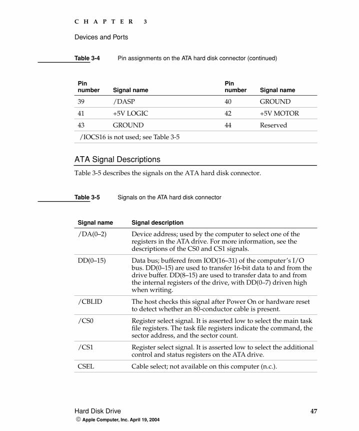
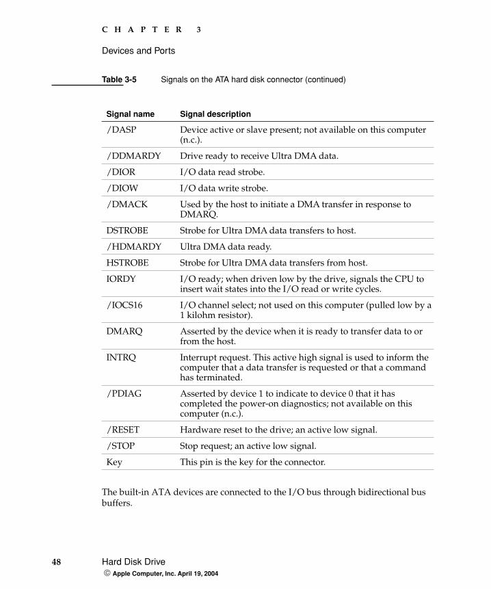
ATA Signal Descriptions
Table 3-5 describes the signals on the ATA hard disk connector.
39 /DASP 40 GROUND
41 +5V LOGIC 42 +5V MOTOR
43 GROUND 44 Reserved
/IOCS16 is not used; see Table 3-5
Table 3-5 Signals on the ATA hard disk connector
Signal name Signal description
/DA(0–2) Device address; used by the computer to select one of the registers in the ATA drive. For more information, see the descriptions of the CS0 and CS1 signals.
DD(0–15) Data bus; buffered from IOD(16–31) of the computer’s I/O bus. DD(0–15) are used to transfer 16-bit data to and from the drive buffer. DD(8–15) are used to transfer data to and from the internal registers of the drive, with DD(0–7) driven high when writing.
/CBLID The host checks this signal after Power On or hardware reset to detect whether an 80-conductor cable is present.
/CS0 Register select signal. It is asserted low to select the main task file registers. The task file registers indicate the command, the sector address, and the sector count.
/CS1 Register select signal. It is asserted low to select the additional control and status registers on the ATA drive.
CSEL Cable select; not available on this computer (n.c.).
Table 3-4 Pin assignments on the ATA hard disk connector (continued)
Pin number Signal name
Pin number Signal name
48 Hard Disk Drive Apple Computer, Inc. April 19, 2004
C H A P T E R 3
Devices and Ports
The built-in ATA devices are connected to the I/O bus through bidirectional bus buffers.
/DASP Device active or slave present; not available on this computer (n.c.).
/DDMARDY Drive ready to receive Ultra DMA data.
/DIOR I/O data read strobe.
/DIOW I/O data write strobe.
/DMACK Used by the host to initiate a DMA transfer in response to DMARQ.
DSTROBE Strobe for Ultra DMA data transfers to host.
/HDMARDY Ultra DMA data ready.
HSTROBE Strobe for Ultra DMA data transfers from host.
IORDY I/O ready; when driven low by the drive, signals the CPU to insert wait states into the I/O read or write cycles.
/IOCS16 I/O channel select; not used on this computer (pulled low by a 1 kilohm resistor).
DMARQ Asserted by the device when it is ready to transfer data to or from the host.
INTRQ Interrupt request. This active high signal is used to inform the computer that a data transfer is requested or that a command has terminated.
/PDIAG Asserted by device 1 to indicate to device 0 that it has completed the power-on diagnostics; not available on this computer (n.c.).
/RESET Hardware reset to the drive; an active low signal.
/STOP Stop request; an active low signal.
Key This pin is the key for the connector.
Table 3-5 Signals on the ATA hard disk connector (continued)
Signal name Signal description
C H A P T E R 3
Devices and Ports
CD-ROM Drive 49 Apple Computer, Inc. April 19, 2004
CD-ROM Drive
Some configurations of the iBook have an internal, slot-loading CD-ROM drive. The drive supports a maximum 24X data transfer rates using constant angular velocity (CAV).
The CD-ROM drive supports the worldwide standards and specifications for CD-ROM and CD-digital audio discs described in the Sony/Philips Yellow Book and Red Book. The drive can read CD-ROM, CD-ROM XA, CD-I, PhotoCD, and Video CD discs as well as play standard audio discs.
Digital audio signals from the CD-ROM can be played through the sound outputs under the control of the System Preferences.
ImportantThe CD-ROM drive supports only 12 cm disc media. It does not support 8 cm discs or noncircular media.
Combo Drive
Some configurations of the computer have a slot-loading, combination DVD-ROM and CD-RW drive.
50 SuperDrive Apple Computer, Inc. April 19, 2004
C H A P T E R 3
Devices and Ports
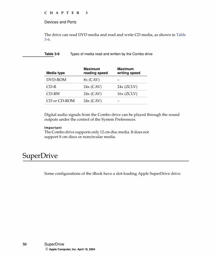
The drive can read DVD media and read and write CD media, as shown in Table 3-6.
Digital audio signals from the Combo drive can be played through the sound outputs under the control of the System Preferences.
ImportantThe Combo drive supports only 12 cm disc media. It does not support 8 cm discs or noncircular media.
SuperDrive
Some configurations of the iBook have a slot-loading Apple SuperDrive drive.
Table 3-6 Types of media read and written by the Combo drive
Media typeMaximum reading speed
Maximumwriting speed
DVD-ROM 8x (CAV) –
CD-R 24x (CAV) 24x (ZCLV)
CD-RW 24x (CAV) 16x (ZCLV)
CD or CD-ROM 24x (CAV) –
C H A P T E R 3
Devices and Ports
Trackpad 51 Apple Computer, Inc. April 19, 2004
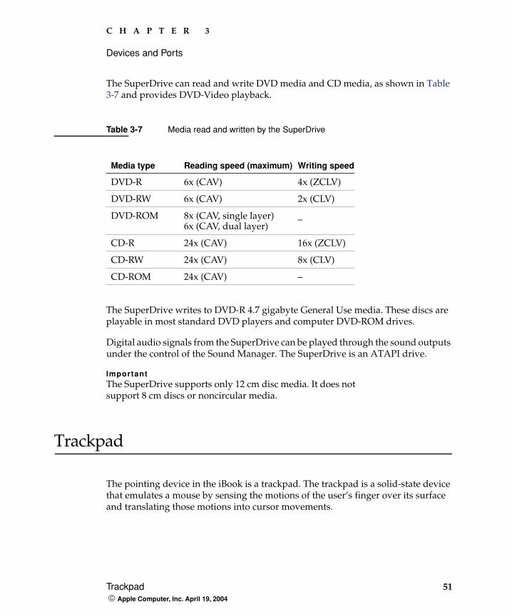
The SuperDrive can read and write DVD media and CD media, as shown in Table 3-7 and provides DVD-Video playback.
The SuperDrive writes to DVD-R 4.7 gigabyte General Use media. These discs are playable in most standard DVD players and computer DVD-ROM drives.
Digital audio signals from the SuperDrive can be played through the sound outputs under the control of the Sound Manager. The SuperDrive is an ATAPI drive.
ImportantThe SuperDrive supports only 12 cm disc media. It does not support 8 cm discs or noncircular media.
Trackpad
The pointing device in the iBook is a trackpad. The trackpad is a solid-state device that emulates a mouse by sensing the motions of the user’s finger over its surface and translating those motions into cursor movements.
Table 3-7 Media read and written by the SuperDrive
Media type Reading speed (maximum) Writing speed
DVD-R 6x (CAV) 4x (ZCLV)
DVD-RW 6x (CAV) 2x (CLV)
DVD-ROM 8x (CAV, single layer)6x (CAV, dual layer)
_
CD-R 24x (CAV) 16x (ZCLV)
CD-RW 24x (CAV) 8x (CLV)
CD-ROM 24x (CAV) –

52 Keyboard Apple Computer, Inc. April 19, 2004
C H A P T E R 3
Devices and Ports
The user makes selections either by pressing the trackpad button (below the trackpad) or by tapping and double tapping on the pad itself. The trackpad responds to one or two taps on the pad itself as one or two clicks of the button. The user can tap and drag on the trackpad in much the same manner as clicking and dragging with the mouse. The tap and double-tap functions are optional; the user activates or deactivates them by means of the keyboard and mouse pane in System Preferences.
The trackpad on the iBook has palm-rejection capabilities that help prevent unintended trackpad input while typing is being performed. When the “Ignore trackpad while typing” checkbox is selected on the mouse pane of Systems Preferences, the system software attempts to filter out unintended contact with the trackpad. The trackpad will not respond when a mouse is present and the “Ignore trackpad when mouse is present” checkbox is selected on the keyboard mouse pane of Systems Preferences. The default setting is for all gestures to be turned off.
Keyboard
The keyboard is a compact, low-profile design with a row of function keys and inverted-T cursor motion keys.
Removing the KeyboardThe keyboard is removable to allow access to the internal components and expansion connectors inside the computer. The keyboard is held in place by a locking screw and two latches.
To unlock the keyboard, the user turns a slotted screw that is part of the Num Lock LED, which is between the F5 and F6 function keys. Turning the screw 180° locks or unlocks the keyboard.
Note: If the trackpad is not responding to intended input, check to see if the “Ignore trackpad while typing” checkbox is selected.
Note: The iBook leaves the factory with keyboard locking screw in the unlocked position.
C H A P T E R 3
Devices and Ports
Keyboard 53 Apple Computer, Inc. April 19, 2004
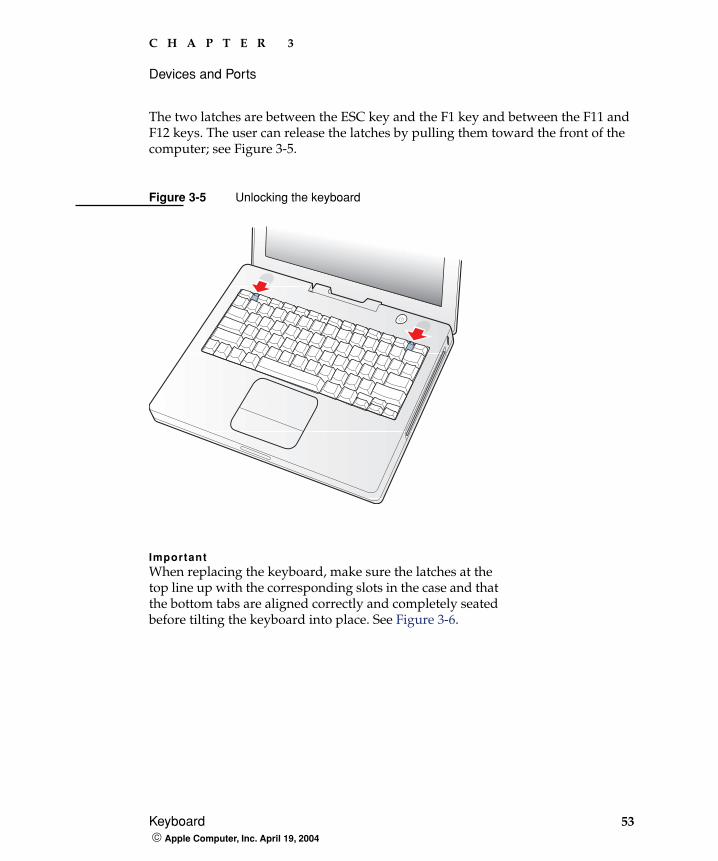
The two latches are between the ESC key and the F1 key and between the F11 and F12 keys. The user can release the latches by pulling them toward the front of the computer; see Figure 3-5.
Figure 3-5 Unlocking the keyboard
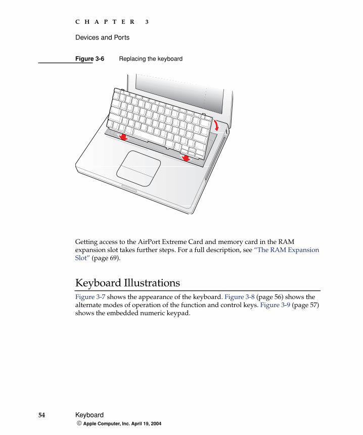
ImportantWhen replacing the keyboard, make sure the latches at the top line up with the corresponding slots in the case and that the bottom tabs are aligned correctly and completely seated before tilting the keyboard into place. See Figure 3-6.
54 Keyboard Apple Computer, Inc. April 19, 2004
C H A P T E R 3
Devices and Ports
Figure 3-6 Replacing the keyboard
Getting access to the AirPort Extreme Card and memory card in the RAM expansion slot takes further steps. For a full description, see “The RAM Expansion Slot” (page 69).
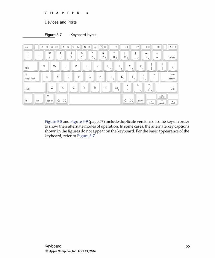
Keyboard IllustrationsFigure 3-7 shows the appearance of the keyboard. Figure 3-8 (page 56) shows the alternate modes of operation of the function and control keys. Figure 3-9 (page 57) shows the embedded numeric keypad.
C H A P T E R 3
Devices and Ports
Keyboard 55 Apple Computer, Inc. April 19, 2004
Figure 3-7 Keyboard layout
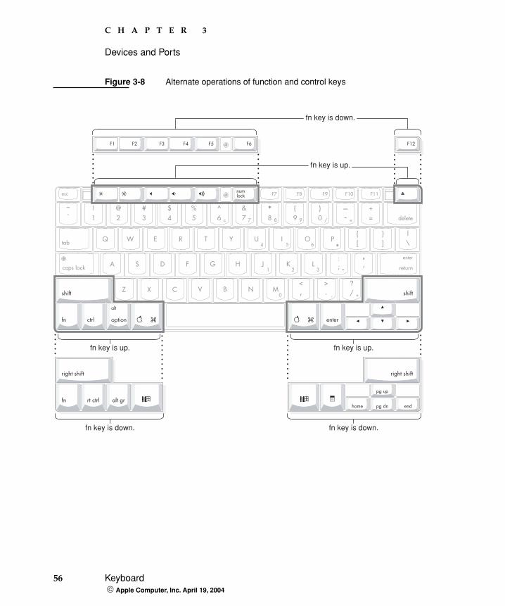
Figure 3-8 and Figure 3-9 (page 57) include duplicate versions of some keys in order to show their alternate modes of operation. In some cases, the alternate key captions shown in the figures do not appear on the keyboard. For the basic appearance of the keyboard, refer to Figure 3-7.
?
56 Keyboard Apple Computer, Inc. April 19, 2004
C H A P T E R 3
Devices and Ports
Figure 3-8 Alternate operations of function and control keys
fn key is up.
fn key is down.
fn key is up.
fn key is down.
fn key is up.
fn key is down.
C H A P T E R 3
Devices and Ports
Keyboard 57 Apple Computer, Inc. April 19, 2004
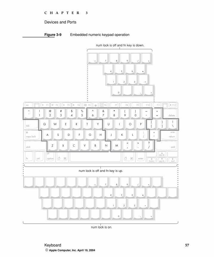
Figure 3-9 Embedded numeric keypad operation
?
num lock is off and fn key is down.
num lock is off and fn key is up.
num lock is on.
58 Keyboard Apple Computer, Inc. April 19, 2004
C H A P T E R 3
Devices and Ports
Keyboard OperationsSeveral of the keys on the keyboard have more than one mode of operation.
� Function keys F1–F6 can also control the display brightness, speaker volume, and the Num Lock function; function key F12 is also the media eject key.
� Certain control keys can be used as page-control keys.
� The keys on the right side of the keyboard can be used as a numeric keypad.
The next sections describe these groups of keys and the way their alternate modes of operation are selected by using the Fn key and the Num Lock key.
Using the Fn Key
Pressing the Fn key affects three sets of keys: the function keys F1–F12, the embedded numeric keypad, and certain modifier keys.
� It toggles the function keys between their control-button operation and their F1–F12 functions, as shown in Table 3-10 (page 61) and Figure 3-8 (page 56).
� It selects the embedded numeric keypad on the right portion of the alphanumeric keys, as shown in Table 3-8 (page 59) and Figure 3-9 (page 57).
� It changes certain control keys, including the cursor control keys, to page control keys, as shown in Table 3-10 (page 61) and Figure 3-9 (page 57).
Using the Num Lock Key
Pressing the Num Lock key affects two sets of keys: the embedded keypad and the rest of the alphanumeric keys.
� It selects the embedded numeric keypad, as shown in Table 3-8 (page 59) and Figure 3-9 (page 57).
� It makes the rest of the alphanumeric keys functionless (NOPs), as shown in Figure 3-9 (page 57).
Note: Mac OS X supports user-programmable function key assignments.
C H A P T E R 3
Devices and Ports
Keyboard 59 Apple Computer, Inc. April 19, 2004
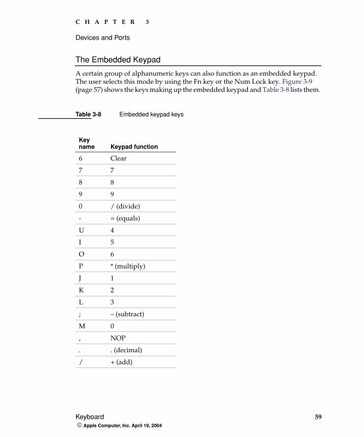
The Embedded Keypad
A certain group of alphanumeric keys can also function as an embedded keypad. The user selects this mode by using the Fn key or the Num Lock key. Figure 3-9 (page 57) shows the keys making up the embedded keypad and Table 3-8 lists them.
Table 3-8 Embedded keypad keys
Key name Keypad function
6 Clear
7 7
8 8
9 9
0 / (divide)
- = (equals)
U 4
I 5
O 6
P * (multiply)
J 1
K 2
L 3
; – (subtract)
M 0
, NOP
. . (decimal)
/ + (add)
60 Keyboard Apple Computer, Inc. April 19, 2004
C H A P T E R 3
Devices and Ports
When the embedded keypad is made active by the Num Lock key, the other alphanumeric keys have no operation (NOP), as shown in Figure 3-9 (page 57). The affected keys include certain special character keys: plus and equal sign, right and left brackets, vertical bar and backslash, and straight apostrophe.
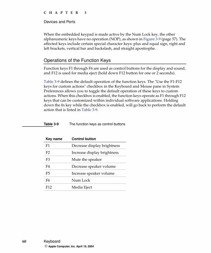
Operations of the Function Keys
Function keys F1 through F6 are used as control buttons for the display and sound, and F12 is used for media eject (hold down F12 button for one or 2 seconds).
Table 3-9 defines the default operation of the function keys. The "Use the F1-F12 keys for custom actions" checkbox in the Keyboard and Mouse pane in System Preferences allows you to toggle the default operation of these keys to custom actions. When this checkbox is enabled, the function keys operate as F1 through F12 keys that can be customized within individual software applications. Holding down the fn key while the checkbox is enabled, will go back to perform the default action that is listed in Table 3-9.
Table 3-9 The function keys as control buttons
Key name Control button
F1 Decrease display brightness
F2 Increase display brightness
F3 Mute the speaker
F4 Decrease speaker volume
F5 Increase speaker volume
F6 Num Lock
F12 Media Eject

C H A P T E R 3
Devices and Ports
Flat Panel Display 61 Apple Computer, Inc. April 19, 2004
Other Control Keys
The cursor control keys can also be used as page control keys. Other control keys can take on the functions of certain keys on a PC keyboard, for use with PC emulation software. The Fn key controls the modes of operation of this group of keys. Table 3-10 is a list of these keys and their alternate functions. These control keys are also show in Figure 3-9 (page 57).
Flat Panel Display
The iBook has a built-in color flat panel display. The display is backlit by a cold cathode fluorescent lamp (CCFL). The display uses TFT (thin-film transistor) technology for high contrast and fast response.
Depending on the model, the display is either 12.1 or 14.1 inches in size, measured diagonally. The display contains 1024x768 pixels (XGA) and can show up to millions of colors.
Table 3-10 Control keys that change
Key name Alternate function
Shift Right shift key
Control Right control key
Option Alt gr (right Alt key)
Command Windows® key
Enter Menu key (for contextual menus)
Left arrow Home
Up arrow Page up
Down arrow Page down
Right arrow End
62 External Display Port Apple Computer, Inc. April 19, 2004
C H A P T E R 3
Devices and Ports
The graphics controller IC is an ATI Mobility Radeon 9200. The graphics IC has 32 MB of video DDR SDRAM on the chip. It supports 3D acceleration and display depths up to 24 bits per pixel. For more information, see “Graphics IC” (page 26).
The graphics IC includes a scaling function that expands smaller-sized images to fill the screen. By means of the scaling function, the computer can show full-screen images at 1024x768, 800x600, or 640x480 pixels.
External Display Port
The iBook has a video output port for connecting an external video monitor or projector. The port supports both RGB and composite/S-video signals (for VGA and video) by means of adapters. The port detects the type of adapter connected to it and programs the graphics IC to provide the appropriate type of video signals, as shown in Table 3-11.
Resolutions supported are 640x480, 800x600, and 1024x768 pixels. When either type of display adapter is connected, the settings for the resolutions are selectable in the Systems Preferences Display pane.
Note: When a dongle is attached to a display, connect the dongle to the display before plugging the dongle into the computer.
Table 3-11 Display adapters
Adapter type Video signals Connector type(s)
VGA RGB VGA 15-pin miniature D-type
Video Composite and S-video TV signals
RCA and S-video
C H A P T E R 3
Devices and Ports
External Display Port 63 Apple Computer, Inc. April 19, 2004
Composite video and S-video signals can be displayed on either an NTSC display or a PAL display. When a display is connected by way of the video adapter, the computer detects the type of adapter and enables the composite and S-video outputs. The settings for the resolutions and standards (NTSC or PAL) are then selectable in the Systems Preferences Display pane.
The video output mirrors the flat panel display: internal and external video share the same buffer, and the hardware sends the image to both displays.
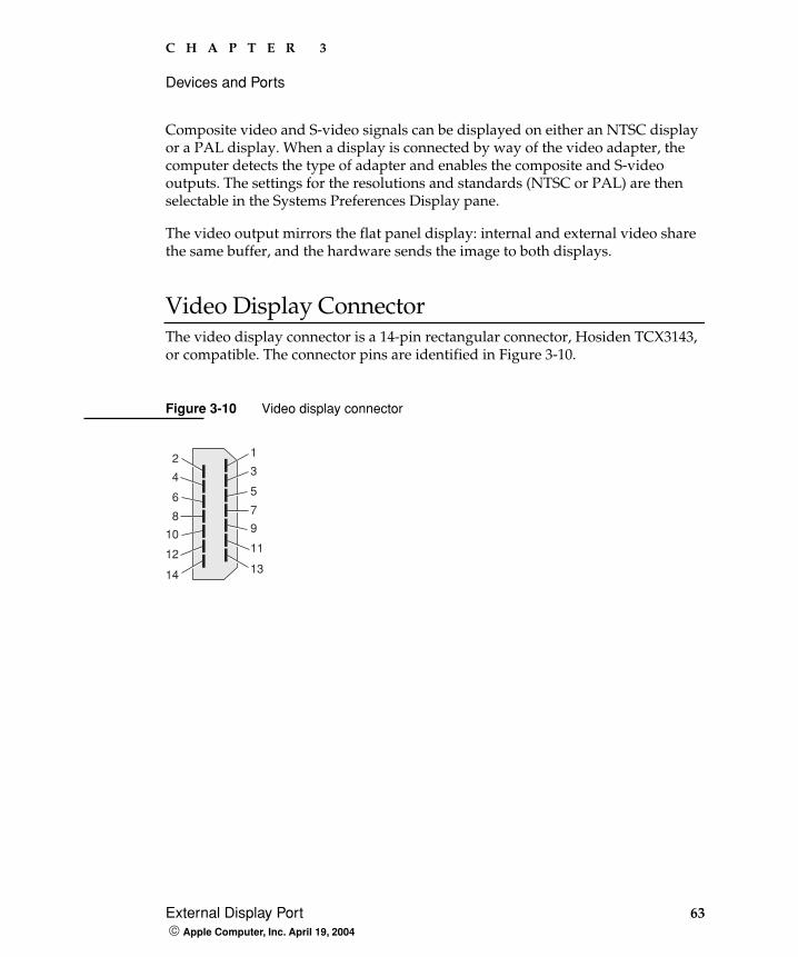
Video Display ConnectorThe video display connector is a 14-pin rectangular connector, Hosiden TCX3143, or compatible. The connector pins are identified in Figure 3-10.
Figure 3-10 Video display connector
2
4
6
8
10
12
14
1
3
5
7
9
11
13
64 External Display Port Apple Computer, Inc. April 19, 2004
C H A P T E R 3
Devices and Ports
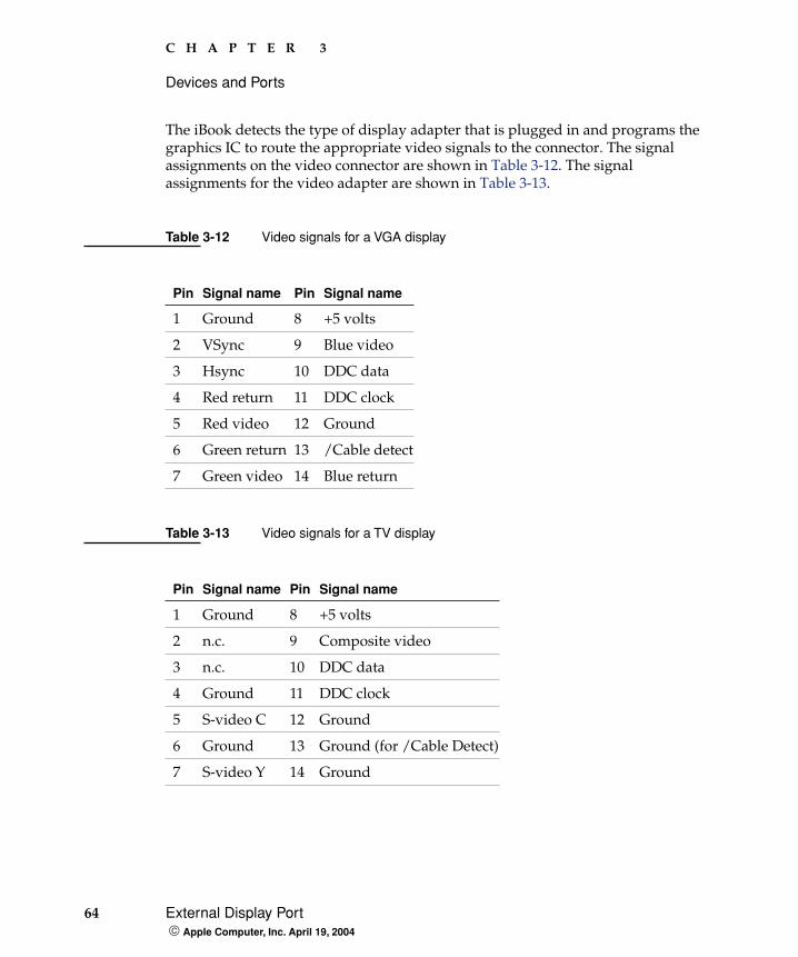
The iBook detects the type of display adapter that is plugged in and programs the graphics IC to route the appropriate video signals to the connector. The signal assignments on the video connector are shown in Table 3-12. The signal assignments for the video adapter are shown in Table 3-13.
Table 3-12 Video signals for a VGA display
Pin Signal name Pin Signal name
1 Ground 8 +5 volts
2 VSync 9 Blue video
3 Hsync 10 DDC data
4 Red return 11 DDC clock
5 Red video 12 Ground
6 Green return 13 /Cable detect
7 Green video 14 Blue return
Table 3-13 Video signals for a TV display
Pin Signal name Pin Signal name
1 Ground 8 +5 volts
2 n.c. 9 Composite video
3 n.c. 10 DDC data
4 Ground 11 DDC clock
5 S-video C 12 Ground
6 Ground 13 Ground (for /Cable Detect)
7 S-video Y 14 Ground
C H A P T E R 3
Devices and Ports
Sound System 65 Apple Computer, Inc. April 19, 2004
The cable detect function on pin 13 is implemented by connecting pin 13 to ground in the display cable. The computer detects the video adapter by reading its EDID (Extended Display Identification Data) via DDC (pins 10 and 11).
The video display connector is compliant with the VESA specification (DDC version 3).
Older Monitors Not SupportedThe computer supports current video monitors. The detection scheme on some older monitors are not supported and will use default configurations, including the following Apple monitors:
� Multiple Scan 17
� Multiple Scan 20
� AudioVision 14
� Apple Hi-Res RGB
� Apple 16" Color
� Apple Hi-Res Monochrome
� Macintosh 12" RGB
Sound System
The 16-bit stereo audio circuitry provides sound input through the built-in microphone and the USB port and sound output through the built-in stereo speakers and the audio minijack.
All audio is handled digitally inside the computer, including audio data from the optical drive, the modem, and devices connected to the USB and FireWire ports. Sound data is converted to analog form only for output to the internal speakers and the headphone jack.
66 Sound System Apple Computer, Inc. April 19, 2004
C H A P T E R 3
Devices and Ports
The sound circuitry handles audio data as 44.1 kHz 16-bit samples. If audio data sampled at a lower rate on another computer is played as output, the Sound Manager transparently upsamples the data to 44.1 kHz prior to sending the audio data to the sound circuitry.
Audio Headphone PortThe audio headphone port is located on the left side of the computer at the left palm rest. The port accepts a standard stereo mini-plug.
The stereo audio signals at the jack are configured to drive a pair of low-impedance stereo headphones. External powered speakers may also be connected to the headphone jack.
The audio signals on the audio minijack have the following electrical characteristics:
� output impedance: 16 ohms each channel
� minimum recommended load impedance: 32 ohms each channel
� maximum level: 1.5 V rms (4.4 V P-P)
� signal to noise ratio (SNR): greater than 98 dB (A)
� THD+N: less than 0.005%
Internal MicrophoneThe computer has a built-in microphone located at the upper right hand corner of the display.
Internal SpeakersThe computer has a stereo pair of speakers located between the keyboard and the display. The sound system provides parametric equalization for the speakers. The computer turns off the sound signal to the speakers when headphones are connected to the audio mini-jack and when USB speakers are active.
C H A P T E R 3
Devices and Ports
Sound System 67 Apple Computer, Inc. April 19, 2004
Sound effects and output from other audio sources can be specified in the System Preferences Sound panel. An output device is displayed on the Sound panel when the computer detects that it is plugged in. The system default setting is the internal audio controller. Once the default is changed to a different device, it will remain the default as long as the device is plugged in.
Internal ModemDigital audio data from the modem is read from the I2S interface, processed by the audio software, and transferred by the DMA through the I2S interface of the Intrepid IC to the sound system.
CD AudioDigital audio data from the optical drive is read using the ATA interface, processed by the audio software, and then transferred by DMA through the I2S interface of the Intrepid IC to the sound system or sent to USB speakers.
Note: Unlike Mac OS 9, Mac OS X does not automatically switch to USB audio when the device is attached.

68 Sound System Apple Computer, Inc. April 19, 2004
C H A P T E R 3
Devices and Ports

The RAM Expansion Slot 69 Apple Computer, Inc. April 19, 2004
C H A P T E R 4
4 RAM Expansion
This chapter tells how to gain access to the RAM expansion slot in the iBook and then describes the RAM expansion module.
The RAM Expansion Slot
The iBook has one RAM expansion slot. To get access to the RAM expansion slot, the user must open up the computer. Below is an overview of the steps for opening the computer; for complete instructions, refer to your iBook User Guide.
ImportantThe user should be reminded to observe the usual precautions to avoid damage to the electronic components due to static electricity.
1. Shut down the computer.
2. Unplug the AC adapter from the computer.
3. Remove the battery from the computer.
4. Release the two plastic tabs located at the top of the keyboard and pull only on the latches (not on the keys) to lift the keyboard up and turn it over, without disconnecting the keyboard’s membrane cable. See Figure 3-5 (page 53).
5. Remove the AirPort Extreme Card, if present, by unlatching the formed wire holder on the card, then pulling the flex tab to remove the module. The antenna cable should remain attached to the card. See Figure 4-1.
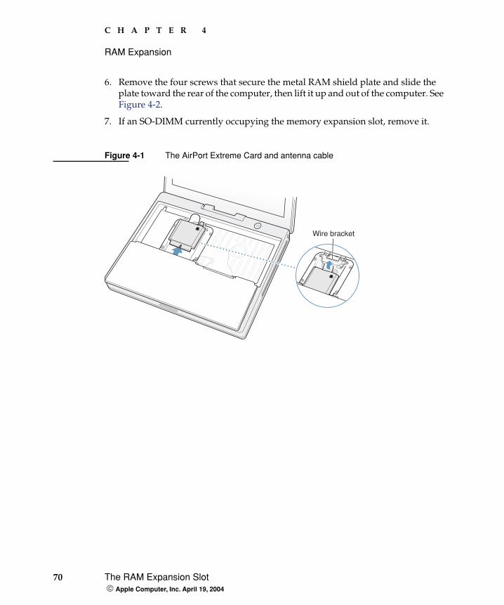
70 The RAM Expansion Slot Apple Computer, Inc. April 19, 2004
C H A P T E R 4
RAM Expansion
6. Remove the four screws that secure the metal RAM shield plate and slide the plate toward the rear of the computer, then lift it up and out of the computer. See Figure 4-2.
7. If an SO-DIMM currently occupying the memory expansion slot, remove it.
Figure 4-1 The AirPort Extreme Card and antenna cable
Wire bracket
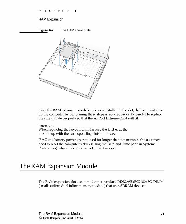
C H A P T E R 4
RAM Expansion
The RAM Expansion Module 71 Apple Computer, Inc. April 19, 2004
Figure 4-2 The RAM shield plate
Once the RAM expansion module has been installed in the slot, the user must close up the computer by performing these steps in reverse order. Be careful to replace the shield plate properly so that the AirPort Extreme Card will fit.
ImportantWhen replacing the keyboard, make sure the latches at the top line up with the corresponding slots in the case.
If AC and battery power are removed for longer than ten minutes, the user may need to reset the computer’s clock (using the Data and Time pane in Systems Preferences) when the computer is turned back on.
The RAM Expansion Module
The RAM expansion slot accommodates a standard DDR266B (PC2100) SO-DIMM (small outline, dual inline memory module) that uses SDRAM devices.
72 The RAM Expansion Module Apple Computer, Inc. April 19, 2004
C H A P T E R 4
RAM Expansion
ImportantA RAM expansion SO-DIMM for the iBook must use DDR SDRAM devices. If the user installs an SO-DIMM that uses EDO or SGRAM devices, the computer will beep twice when the user attempts to restart the computer.
An SO-DIMM for the iBook can contain either 128, 256, 512 MB, or 1 GB of memory. Maximum supported RAM capacity is 1.25 MB and is limited by the space available for the SO-DIMM.
Mechanical Design of the RAM SO-DIMM The mechanical characteristics of the RAM expansion module are given in the JEDEC specification JESD95 for the 200-pin 8-byte DRAM SO-DIMM. To find out how to obtain the specification, see “RAM Expansion Modules” (page 80).
The specification defines SO-DIMMs with nominal heights of 1.0, 1.25, 1.5, or 2.0 inches. The iBook can accommodate standard SO-DIMMs with a height of 1.0 or 1.25 inches.
The JEDEC specification defines the maximum depth or thickness of an SO-DIMM as 4.0 mm . That specification is also a maximum; modules that exceed the specified thickness can cause reliability problems.
Electrical Design of the RAM SO-DIMMThe electrical characteristics of the RAM SO-DIMM are given in section 4.5.6 of the JEDEC Standard 21-C, release 7. To find out how to obtain the specification, see “RAM Expansion Modules” (page 80).
The specification defines several attributes of the DIMM, including storage capacity and configuration, connector pin assignments, and electrical loading. The specification supports SO-DIMMs with either one or two banks of memory.
The JEDEC specification for the SO-DIMM defines a Serial Presence Detect (SPD) feature that contains the attributes of the module. SO-DIMMs for use in the iBook are required to have the SPD feature. Information about the required values to be stored in the presence detect EEPROM is in section 4.1.2.5 and Figure 4.5.6–C (200-pin SDRAM SO–DIMM, PD INFORMATION) of the JEDEC standard 21-C specification, release 7.
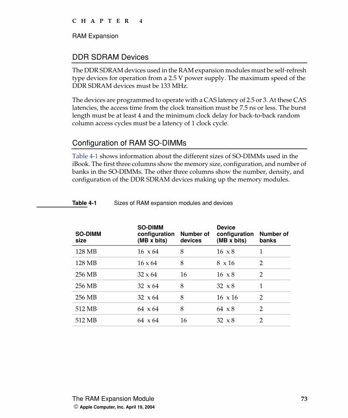
C H A P T E R 4
RAM Expansion
The RAM Expansion Module 73 Apple Computer, Inc. April 19, 2004
DDR SDRAM Devices
The DDR SDRAM devices used in the RAM expansion modules must be self-refresh type devices for operation from a 2.5 V power supply. The maximum speed of the DDR SDRAM devices must be 133 MHz.
The devices are programmed to operate with a CAS latency of 2.5 or 3. At these CAS latencies, the access time from the clock transition must be 7.5 ns or less. The burst length must be at least 4 and the minimum clock delay for back-to-back random column access cycles must be a latency of 1 clock cycle.
Configuration of RAM SO-DIMMs
Table 4-1 shows information about the different sizes of SO-DIMMs used in the iBook. The first three columns show the memory size, configuration, and number of banks in the SO-DIMMs. The other three columns show the number, density, and configuration of the DDR SDRAM devices making up the memory modules.
Table 4-1 Sizes of RAM expansion modules and devices
SO-DIMMsize
SO-DIMMconfiguration (MB x bits)
Number of devices
Device configuration (MB x bits)
Number of banks
128 MB 16 x 64 8 16 x 8 1
128 MB 16 x 64 8 8 x 16 2
256 MB 32 x 64 16 16 x 8 2
256 MB 32 x 64 8 32 x 8 1
256 MB 32 x 64 8 16 x 16 2
512 MB 64 x 64 8 64 x 8 2
512 MB 64 x 64 16 32 x 8 2
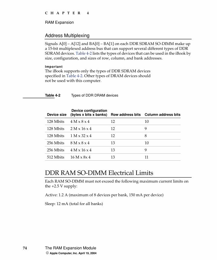
74 The RAM Expansion Module Apple Computer, Inc. April 19, 2004
C H A P T E R 4
RAM Expansion
Address Multiplexing
Signals A[0] – A[12] and BA[0] – BA[1] on each DDR SDRAM SO-DIMM make up a 15-bit multiplexed address bus that can support several different types of DDR SDRAM devices. Table 4-2 lists the types of devices that can be used in the iBook by size, configuration, and sizes of row, column, and bank addresses.
ImportantThe iBook supports only the types of DDR SDRAM devices specified in Table 4-2. Other types of DRAM devices should not be used with this computer.
DDR RAM SO-DIMM Electrical LimitsEach RAM SO-DIMM must not exceed the following maximum current limits on the +2.5 V supply:
Active: 1.2 A (maximum of 8 devices per bank, 150 mA per device)
Sleep: 12 mA (total for all banks)
Table 4-2 Types of DDR DRAM devices
Device size Device configuration (bytes x bits x banks) Row address bits Column address bits
128 Mbits 4 M x 8 x 4 12 10
128 Mbits 2 M x 16 x 4 12 9
128 Mbits 1 M x 32 x 4 12 8
256 Mbits 8 M x 8 x 4 13 10
256 Mbits 4 M x 16 x 4 13 9
512 Mbits 16 M x 8x 4 13 11
C H A P T E R 4
RAM Expansion
The RAM Expansion Module 75 Apple Computer, Inc. April 19, 2004
The maximum current specified for active operation generally rules out the use of 4-bit-wide DDR SDRAM devices in a RAM expansion module. Such a module would have 16 such devices per bank, and the 1.2 A maximum current would allow only about 75 mA per device. To stay within the current limits, RAM expansion modules should use only 8-bit or 16-bit DDR SDRAM devices.

76 The RAM Expansion Module Apple Computer, Inc. April 19, 2004
C H A P T E R 4
RAM Expansion

Apple Technical Notes 77 Apple Computer, Inc. April 19, 2004
A P P E N D I X A
A Supplemental Reference Documents
This section contains additional information about the technologies mentioned in this developer note by providing references to helpful websites.
For information about older models of Macintosh computers, refer to the developer notes archive at:
http://developer.apple.com/documentation/Hardware/hardware2.html
Apple Technical Notes
Apple Technical Notes answer many specific questions about the operation of Macintosh computers and the Mac OS. The technical notes are available on the website at
http://developer.apple.com/technotes/
3D Graphics
Developers of 3D graphics for games should know about OpenGL for Macintosh®, a new version of SGI’s application programming interface (API) and software library for 3D graphics.
General information on OpenGL is available on the World Wide Web at
78 PowerPC G4 Microprocessor Apple Computer, Inc. April 19, 2004
A P P E N D I X A
Supplemental Reference Documents
http://www.apple.com/macosx/technologies/graphics.html
and
http://www.opengl.org
Developer support and documentation is available at
http://developer.apple.com/opengl/
PowerPC G4 Microprocessor
Information about the PowerPC G4 microprocessor is available on the World Wide Web at
http://e-www.motorola.com/webapp/sps/site/prod_summary.jsp?code=MPC7447A&nodeId=018rH3bTdG8653
Mac OS X
Mac OS X version 10.3.3 is installed by default on the iBook computer. For access to Apple’s developer documentation for Mac OS X, see the Apple Developer Connection (ADC) website at
http://developer.apple.com/documentation/MacOSX/MacOSX.html
O'Reilly & Associates publishes a series of books about Mac OS X development. The books in this series have been technically reviewed by Apple engineers and are recommended by the Apple Developer Connection.

A P P E N D I X A
Supplemental Reference Documents
I/O Kit 79 Apple Computer, Inc. April 19, 2004
I/O Kit
The I/O Kit is part of Darwin, the operating system foundation for Mac OS X. The documentation for I/O Kit is available on Apple’s Darwin website at
http://developer.apple.com/documentation/Darwin/Darwin.html
Open Firmware
The following technical notes provide an introduction to Open Firmware on the Macintosh platform:
TN1061: Open Firmware, Part I, available on the technical note web site at
http://developer.apple.com/technotes/tn/tn1061.html
TN1062: Open Firmware, Part II, available on the technical note web site at
http://developer.apple.com/technotes/tn/tn1062.html
TN1044: Open Firmware, Part III, available on the technical note web site at
http://developer.apple.com/technotes/tn/tn1044.html
TN2001: Running Files from a Hard Drive in Open Firmware, at
http://developer.apple.com/technotes/tn/tn2001.html
Another technical note tells how to debug open firmware code. Please refer to TN2004: Debugging Open Firmware Using Telnet, available on the technical note web site at
http://developer.apple.com/technotes/tn/tn2004.html
80 RAM Expansion Modules Apple Computer, Inc. April 19, 2004
A P P E N D I X A
Supplemental Reference Documents
RAM Expansion Modules
The mechanical characteristics of the DDR RAM SO-DIMM are given in JEDEC specification number JESD95. The specification can be found by using the search string JESD95 on the Electronics Industry Association’s website at
http://www.jedec.org/DOWNLOAD/default.cfm
The electrical characteristics of the DDR RAM SO-DIMM are given in JEDEC Standard 21-C. The specification can be found by using the search string JESD21-C on the Electronics Industry Association’s website at
http://www.jedec.org/DOWNLOAD/default.cfm
ATA Devices
ATA (AT Attachment), also referred to as integrated drive electronics (IDE), is a standard interface used with storage devices such as hard disk drives. For more information on ATA, refer to the following Apple website at
http://developer.apple.com/documentation/Hardware/DeviceManagers/ata/ata.html
Information about the ATA standards is available at the Technical Committee T13 AT Attachment website, at
http://www.t13.org/
A P P E N D I X A
Supplemental Reference Documents
USB Interface 81 Apple Computer, Inc. April 19, 2004
USB Interface
For more information about USB on Macintosh computers, refer to Apple Computer’s Accessing Hardware from Applications. Information is also available at
http://developer.apple.com/hardware/usb/index.html
Mac OS X includes support for a wide variety of USB classes. Detailed specifications on these classes available at
http://www.usb.org/developers/devclass/
For full specifications of the Universal Serial Bus, refer to the USB Implementers Forum on the World Wide Web, at:
http://www.usb.org/developers/docs
FireWire 400 Interface
For additional information about the FireWire 400 IEEE 1394a interface and the Apple APIs for FireWire software, refer to the resources available on the Apple FireWire web site at:
http://developer.apple.com/firewire/index.html
The IEEE 1394 standard is available from the IEEE. Ordering information can be found on the World Wide Web at
http://shop.ieee.org/store
Useful information is also available at the 1394 Trade Association’s web site:
http://www.1394ta.org/
82 Wireless Networks Apple Computer, Inc. April 19, 2004
A P P E N D I X A
Supplemental Reference Documents
Wireless Networks
More information about Wi-Fi and wireless networks using the IEEE 802.11 standard is available on the web site of the WiFi Alliance, at
http://www.wi-fi.org
Bluetooth
For more information regarding Bluetooth technology, refer to the following locations on the World Wide Web.
Bluetooth specification:
http://www.bluetooth.org/spec/
Bluetooth SIG:
http://www.bluetooth.org
Bluetooth developer tools on the Apple web site at:
http://developer.apple.com/hardware/bluetooth
Typographical Conventions 83 Apple Computer, Inc. April 19, 2004
A P P E N D I X B
B Conventions and Abbreviations
This developer note uses the following typographical conventions and abbreviations.
Typographical Conventions
ImportantA note like this contains important information that you should read before proceeding.
Abbreviations
When unusual abbreviations appear in this developer note, the corresponding terms are also spelled out. Standard units of measure and other widely used abbreviations are not spelled out.
Note: A note like this contains information that is of interest but is not essential for an understanding of the text.
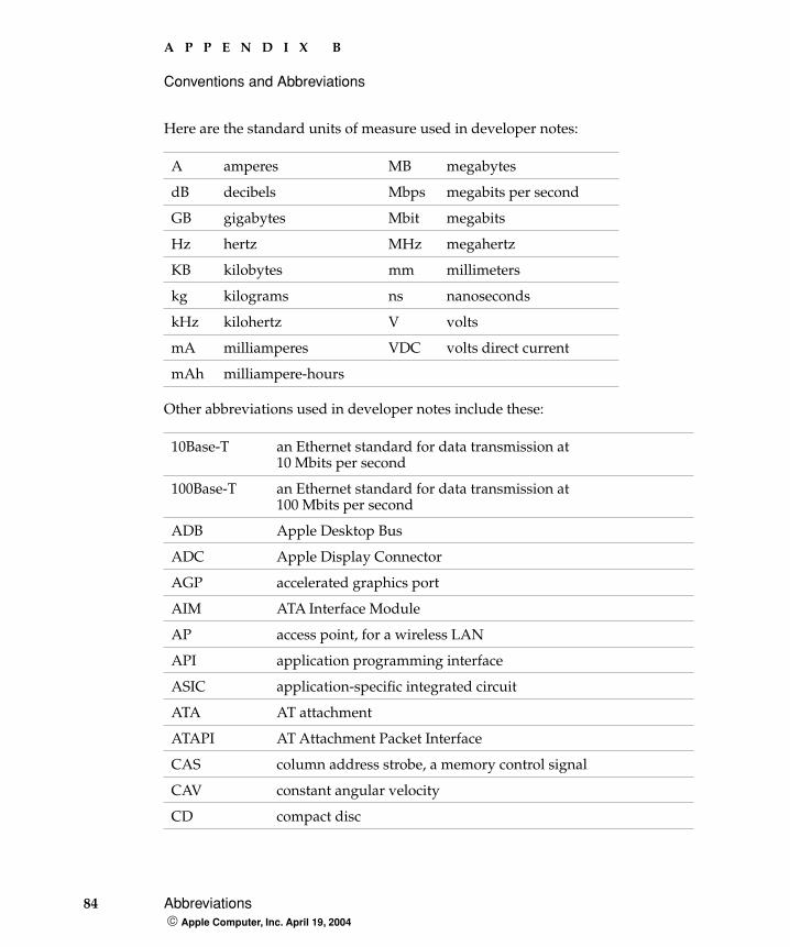
84 Abbreviations Apple Computer, Inc. April 19, 2004
A P P E N D I X B
Conventions and Abbreviations
Here are the standard units of measure used in developer notes:
Other abbreviations used in developer notes include these:
A amperes MB megabytes
dB decibels Mbps megabits per second
GB gigabytes Mbit megabits
Hz hertz MHz megahertz
KB kilobytes mm millimeters
kg kilograms ns nanoseconds
kHz kilohertz V volts
mA milliamperes VDC volts direct current
mAh milliampere-hours
10Base-T an Ethernet standard for data transmission at 10 Mbits per second
100Base-T an Ethernet standard for data transmission at 100 Mbits per second
ADB Apple Desktop Bus
ADC Apple Display Connector
AGP accelerated graphics port
AIM ATA Interface Module
AP access point, for a wireless LAN
API application programming interface
ASIC application-specific integrated circuit
ATA AT attachment
ATAPI AT Attachment Packet Interface
CAS column address strobe, a memory control signal
CAV constant angular velocity
CD compact disc
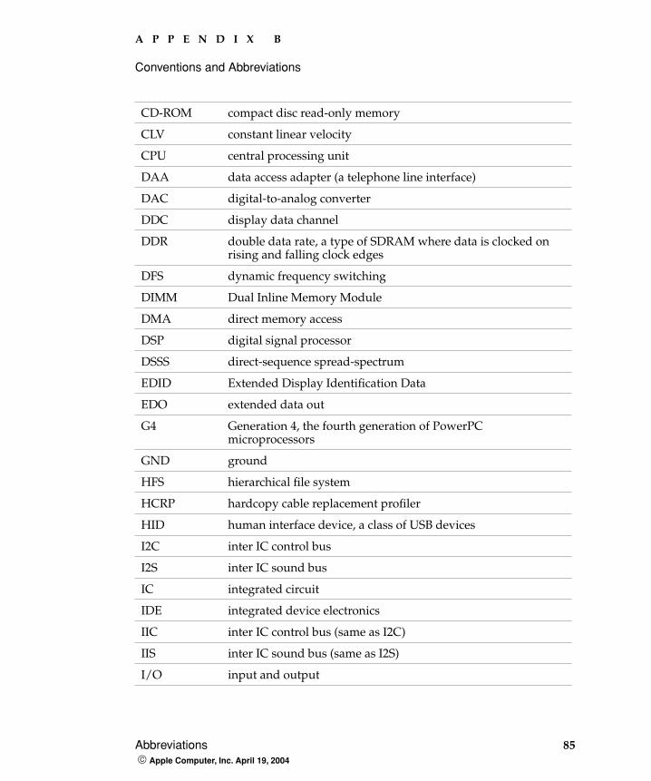
A P P E N D I X B
Conventions and Abbreviations
Abbreviations 85 Apple Computer, Inc. April 19, 2004
CD-ROM compact disc read-only memory
CLV constant linear velocity
CPU central processing unit
DAA data access adapter (a telephone line interface)
DAC digital-to-analog converter
DDC display data channel
DDR double data rate, a type of SDRAM where data is clocked on rising and falling clock edges
DFS dynamic frequency switching
DIMM Dual Inline Memory Module
DMA direct memory access
DSP digital signal processor
DSSS direct-sequence spread-spectrum
EDID Extended Display Identification Data
EDO extended data out
G4 Generation 4, the fourth generation of PowerPC microprocessors
GND ground
HFS hierarchical file system
HCRP hardcopy cable replacement profiler
HID human interface device, a class of USB devices
I2C inter IC control bus
I2S inter IC sound bus
IC integrated circuit
IDE integrated device electronics
IIC inter IC control bus (same as I2C)
IIS inter IC sound bus (same as I2S)
I/O input and output
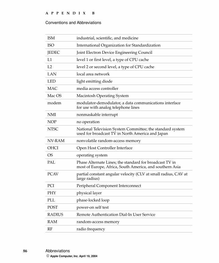
86 Abbreviations Apple Computer, Inc. April 19, 2004
A P P E N D I X B
Conventions and Abbreviations
ISM industrial, scientific, and medicine
ISO International Organization for Standardization
JEDEC Joint Electron Device Engineering Council
L1 level 1 or first level, a type of CPU cache
L2 level 2 or second level, a type of CPU cache
LAN local area network
LED light emitting diode
MAC media access controller
Mac OS Macintosh Operating System
modem modulator-demodulator, a data communications interfacefor use with analog telephone lines
NMI nonmaskable interrupt
NOP no operation
NTSC National Television System Committee; the standard system used for broadcast TV in North America and Japan
NV-RAM nonvolatile random-access memory
OHCI Open Host Controller Interface
OS operating system
PAL Phase Alternate Lines; the standard for broadcast TV in most of Europe, Africa, South America, and southern Asia
PCAV partial constant angular velocity (CLV at small radius, CAV at large radius)
PCI Peripheral Component Interconnect
PHY physical layer
PLL phase-locked loop
POST power-on self test
RADIUS Remote Authentication Dial-In User Service
RAM random-access memory
RF radio frequency
A P P E N D I X B
Conventions and Abbreviations
Abbreviations 87 Apple Computer, Inc. April 19, 2004
rms root mean square
ROM read-only memory
SCC Serial Communications Controller
SDRAM synchronous dynamic RAM
SNR signal to noise ratio
SO-DIMM small outline dual inline memory module
SPD Serial Presence Detect, a feature of the SO-DIMM
USB Universal Serial Bus
TDM target disk mode
VCC positive supply voltage (voltage for collectors)
VESA Video Electronics Standards Association
VGA video graphics adapter
WEP Wired Equivalent Privacy
Wi-Fi Logo used by the Wireless Ethernet Compatibility Alliance for certification of interoperability of 802.11 products
WLAN wireless LAN
ZCLV zone constant linear velocity

88 Abbreviations Apple Computer, Inc. April 19, 2004
A P P E N D I X B
Conventions and Abbreviations
89
Index
Numerals
3D graphics, reference information for 77
A
abbreviations 84–87access to internal components 52, 71airliner power outlet 17, 29AirPort Admin Utility 42AirPort Extreme 30, 40–42
hardware components 41security features 40software components 41
AirPort Extreme Application 41AirPort Extreme Base Station 41AirPort Extreme Setup Assistant 41ATA bus 43, 50ATA disk interface 43ATA hard disk 43
B
backside cache 24block diagram 21Bluetooth 42, 82boot ROM 25booting from a FireWire device 37box flag 17buses 21, 23, 24
C
CD audio 67
CD-ROM drive 49clock speeds 23Combo drive 49composite video 63connectors
Ethernet 38external video display 63FireWire 36hard disk drive 46headphone jack 66modem 39USB 33
custom ICsIntrepid memory and I/O controller IC 24
D
DFS 19displays
flat panel 61DMA support 25, 27DVD-R/CD-RW drive 50DVD-ROM drive 49DVD-ROM/CD-RW drive 49
E
EHCI 30EIDE bus 27, 28Energy Star standard 19Ethernet controller 26Ethernet port 38external display port
monitors not supported 65resolutions supported 63
I N D E X
90
external monitor port 62–65
F
featuresall 12new 11
FireWire connector 36FireWire controller 26FireWire port
booting from 37FireWire ports 35–38
connectors 36FireWire, reference information for 81flat panel display 61function keys, alternate functions of 60
G
G4. See PowerPC G4 microprocessorgestaltMachineType call 17graphics address remapping table (GART) 27graphics IC 26, 62
H
hard disk connector 46pin assignments on 46signals on 47
hard disk drive 43–48connector
ATA signals on 47pin assignments on 46
dimensions and mounting holes 43HCRP profile 42headphone jack 66HID profile 42
I
IDE disk interface. See ATA disk interfaceIDE hard disk 43
See also hard disk driveidentifying the machine 17internal modem 28, 39interrupts 27Intrepid memory and I/O controller IC 24
K
keyboard 52–61control keys with alternate functions 61Fn key 58keys with multiple functions 58Num Lock key 58PMU99 interface for 29removing 52, 71
L
L2 cache 24
M
memory. See RAM expansion modulemicrophone 66microprocessor 23microprocessor clock speeds 23modem 28modem, internal 39monitor adapters 62
N
new features 11NTSC display 63
I N D E X
91
O
OHCI 30Open Firmware, reference information for 79
P
PAL display 63PCI USB 2.0 controller 30peripheral devices 17PMU99 power controller IC 29pointing device (trackpad) 51power control IC 29power management 18power outlet, airliner 17, 29power saving states 18PowerPC G4 microprocessor 23
R
RAM expansion 69–75RAM expansion module 71–75
capacities 72RAM expansion slot, getting access to 69ROM. See boot ROM
S
SDRAM device specifications 73Serial Presence Detect mechanism 72sleep state 18SO-DIMMs 71
address multiplexing on 74configurations 73electrical design of 72electrical limits for 74mechanical design of 72SDRAM device specifications 73Serial Presence Detect mechanism on 72
sound circuitry 28
sound sample rate 65sound system 65–67
CD audio 67electrical characteristics 66internal speakers 66signals to and from the modem 67
speakers 66SuperDrive 50S-video 63system software 17–20
idle state 18machine identification 17sleep state 18Target Disk Mode 20
T
Target Disk Mode 20trackpad 51
PMU99 interface for 29TV display adapter 63
U
Ultra ATA-100 bus 43USB 1.1 controller 28USB 2.0 30USB 2.0 controller IC 30USB 2.0 ports
data transfer speeds 30USB connector 33USB ports 33–35
connectors 33data transfer speeds 34features
storage devices 34USB, reference information for 81
I N D E X
92
V
VGA display 63VGA display adapter 62video adapters 17video display connector 63video port. See external monitor port
W
wireless LAN module. See AirPort Extreme


