IC ENGINES ENGINE A device transferring one form of energy to another Most engine transform thermal to mechanical HEAT ENGINE -Thermal energy to mechanical Types Internal combustion engine External combustion engine Internal combustion engine Combustion within the engine Eg. Diesel engine External combustion engine Combustion outside the engine Eg. steam engine ENGINE COMPONENTS Cylinder Vessel in which a pist on makes reciprocatory motion Piston cyIindrical component fitted into the cylinder movable c0mbustion chamber space cnclosed between the cylinder head and the piston top place where there is increasing pressure due to combustion built up inlet and exhaust valves inlet valve for regulating the incoming charge exhaust valae for discharging the combustion products spark plug initiates combustion in SI engine located on cylinder head
Transcript
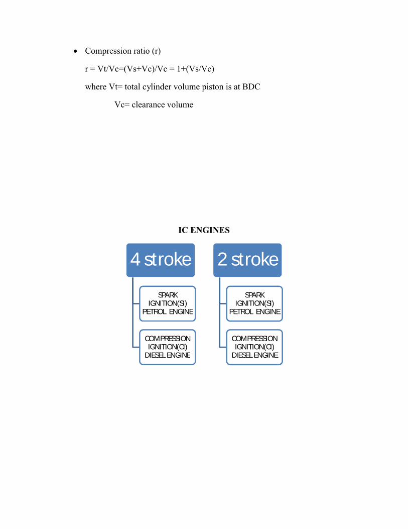
IC ENGINES
ENGINE
A device transferring one form of energy to another
the 4 strokes are suction or intake stroke compression stroke expansion stroke or power stroke exhaust stroke
Suction stroke
Piston moving from TC to BDC Inlet valve opens Exhaust value closes Charge is taken into the cylinder
Combustion stroke
Piston moves from TDC to BDC Inlet valve and exhaust valve closes Entire cylinder volume is compressed to clearence volume At the compression stroke,mixture is ignited with the help of an
electric spark Burning process occurs at the constant volume Burning process -> temperature -> 2000°c Pressure increases due to heat realse
Expansion or power stroke
TDC-> BDC (due to high pressure of burnt gases force) Inlet valve and exhaust valve- closed Useful stroke—power is obtined Pressure and temperature increases
Exhaust stroke
BDC to TDC Inlet valve closed and exhaust vale open Pressure falls to atmospheric level Burnt gases are swept out of the cylinder at the atmospheric
pressure At the end the stroke exhaust valve closes Some residue gases get trapped in the clearence volume Residual gases mixes with the flesh charges forming its working
fluid
In 4s CI engine
Air alone is sent in Diesel is sprayed with nozzle and fuel pump arrangement Due to high compressipn ratio (16-20:1), self ignition occours
2 stroke engines
Instead of valves ports namely inlet port, exhaust port and transfer port
Compression stroke merged with suction stroke Power stroke with exhaust stroke All strokes un one revolution 1 power stroke in one cycle
Functions
EP opens first BDC-> TDC, IP opens – entry of air, simultaneously compression
and combustion takes place TDC->BDC, charge moves through tranfer port – burnt gas moves
through EP
When BDC->TDC, TP closes first and then EP closes during compression
Process then gets repeated
DIFFERENCE BETWEEN FOUR STROKE AND TWO STROKE ENGINE
Four stroke engine Two stroke engineOne power stroke in two revolutions 1 power stroke in 1 revolutionHeavier flywheel needed Lighter flywheel neededPower produced is less Power is large for same size of the
Lesser cooling and lubricationLesser wear and tear
higher cooling and lubricationhigher wear and tear
Initial cost is more Less�v high �v lowThermal � high, part load � is better
Thermal � low, part load � is poor
Used when efficiency is needed Used when low cost compactness,light weight are needed
Eg. In cars, buses, trucks, poergenerators
Two wheelers and hand sprayers
Cycle of operation
Based on the cycle of operation IC engines are classified as
otto cycle engine heat addition at constant volume also called CI engine
diesel cycle engine heat addition at constant pressure also called SI engine
TYPES OF IGNITION SYSTEM
SI engines need external energy stroke to produce spark
Two types 1. Battery ignition
2. magneto ignition
Battery ignition system
Energy from 6v to 12v battery charged by dynamo Ignition switch- turns on or off
Ballast resistor- regulate the primary current
Ignition coil- source of ignition
Energy- a magnetic core of soft iron and 2 insulated conducting coils
Contact braking-making and braking of primary circuit
Spark plug- two electrodes with gap across which high potential develops
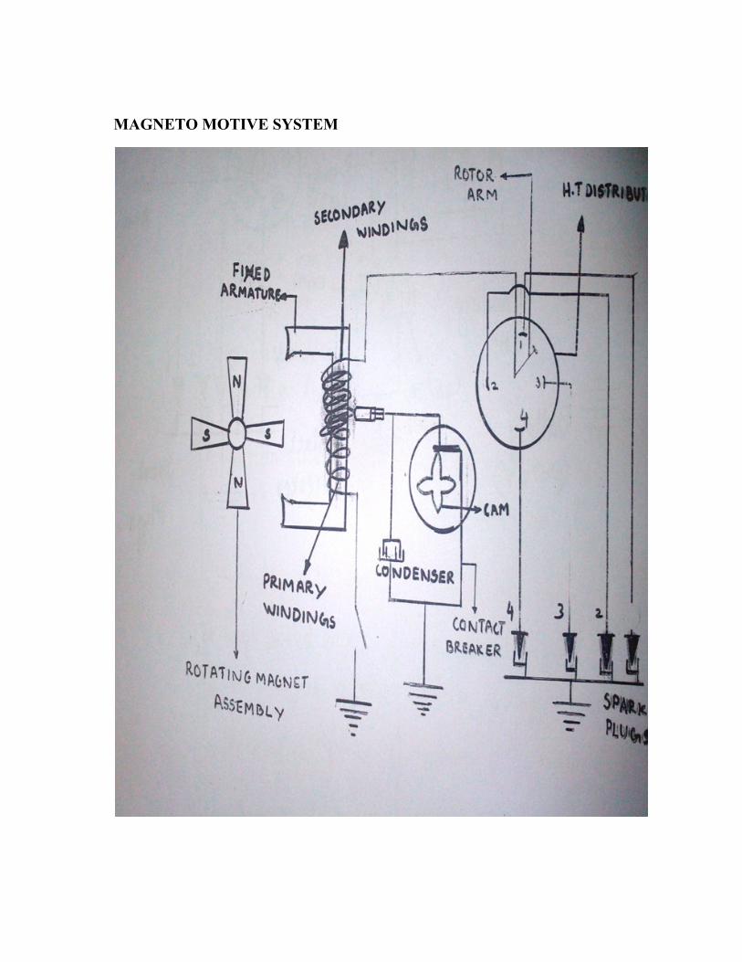
Magneto ignition system
Own generator to provide energy
Replaces all part of battery except spark plug
Rotating magnet-produces high voltage
Three types of magnet Rotating armature type Rotating magnet type Polar inductor type
In the first type Armature rotates, magnet stationary
In the second type Magnet revolves, winding stationary
Working principle same as the battery ignition system
With cam, primary circuit flux change=> high voltage
Best system for high voltage
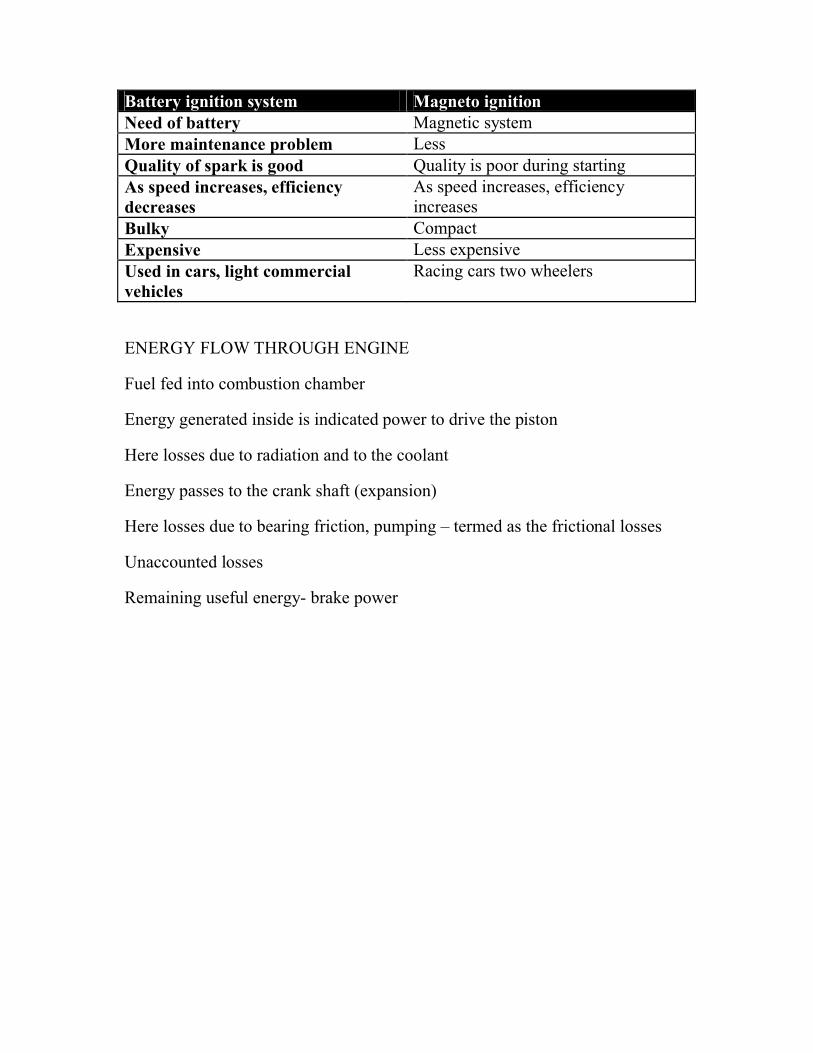
Battery ignition system Magneto ignitionNeed of battery Magnetic systemMore maintenance problem LessQuality of spark is good Quality is poor during startingAs speed increases, efficiency decreases
As speed increases, efficiency increases
Bulky CompactExpensive Less expensiveUsed in cars, light commercial vehicles
Racing cars two wheelers
ENERGY FLOW THROUGH ENGINE
Fuel fed into combustion chamber
Energy generated inside is indicated power to drive the piston
Here losses due to radiation and to the coolant
Energy passes to the crank shaft (expansion)
Here losses due to bearing friction, pumping – termed as the frictional losses
Unaccounted losses
Remaining useful energy- brake power
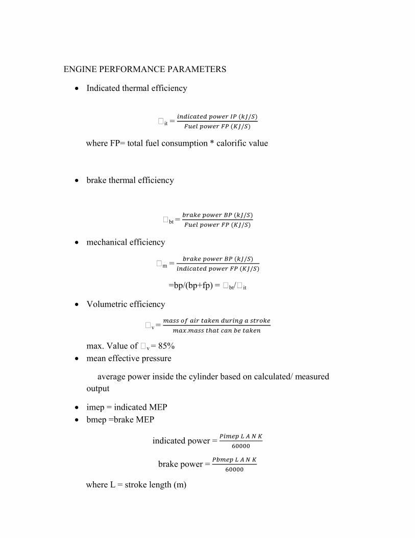
ENGINE PERFORMANCE PARAMETERS
Indicated thermal efficiency
�it = ( / )
( / ) where FP= total fuel consumption * calorific value
brake thermal efficiency
�bt = ( / )
( / ) mechanical efficiency
�m = ( / )
( / )=bp/(bp+fp) = �bt/�it
Volumetric efficiency
�v =
. ℎ max. Value of �v = 85%
mean effective pressure
average power inside the cylinder based on calculated/ measured output
imep = indicated MEP bmep =brake MEP
indicated power =
60000brake power =
60000
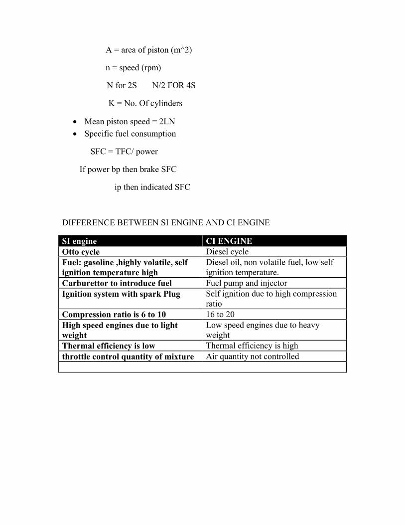
where L = stroke length (m)
A = area of piston (m^2)
n = speed (rpm)
N for 2S N/2 FOR 4S
K = No. Of cylinders
Mean piston speed = 2LN
Specific fuel consumption
SFC = TFC/ power
If power bp then brake SFC
ip then indicated SFC
DIFFERENCE BETWEEN SI ENGINE AND CI ENGINE
SI engine CI ENGINEOtto cycle Diesel cycleFuel: gasoline ,highly volatile, self ignition temperature high
Diesel oil, non volatile fuel, low self ignition temperature.
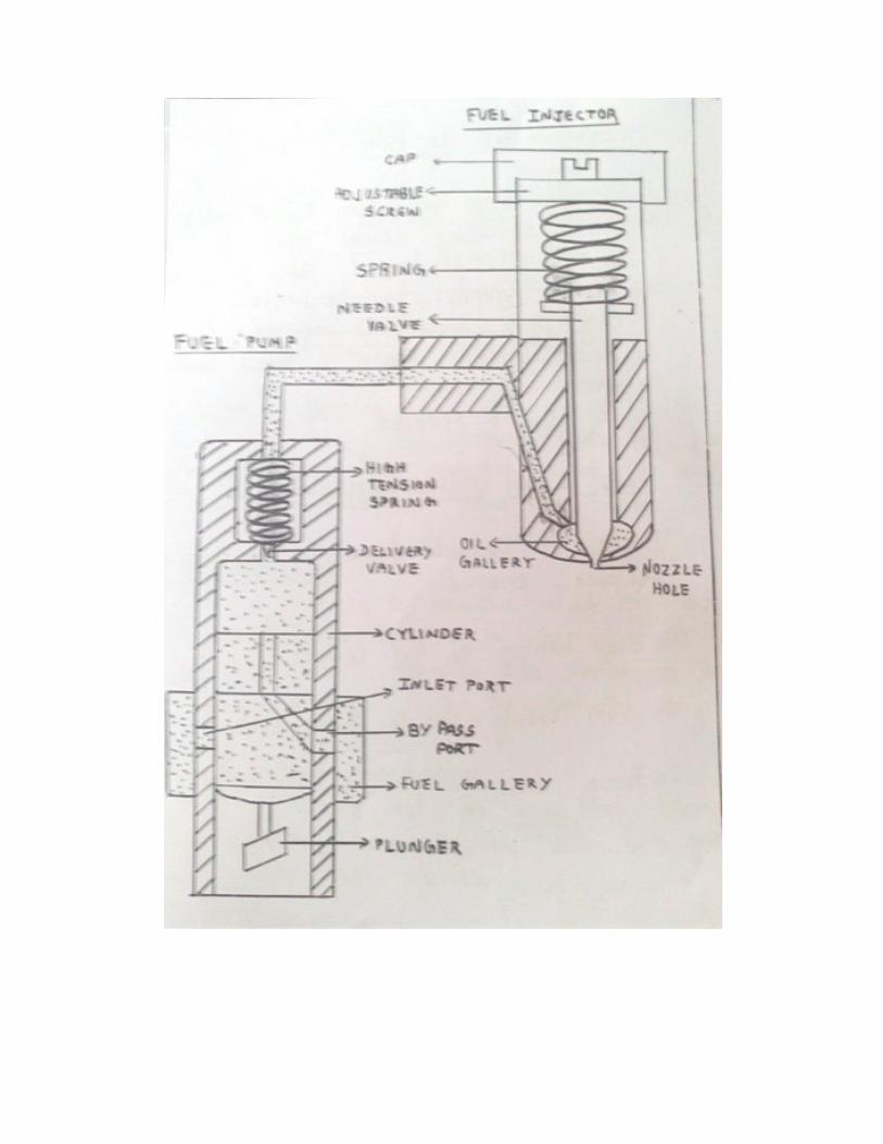
Carburettor to introduce fuel Fuel pump and injectorIgnition system with spark Plug Self ignition due to high compression
ratioCompression ratio is 6 to 10 16 to 20High speed engines due to light weight
Low speed engines due to heavy weight
Thermal efficiency is low Thermal efficiency is highthrottle control quantity of mixture Air quantity not controlled
MAGNETO MOTIVE SYSTEMMAGNETO MOTIVE SYSTEM
COIL IGNITION FOR A FOUR CYLINDER ENGINE COIL IGNITION FOR A FOUR CYLINDER ENGINE COIL IGNITION FOR A FOUR CYLINDER ENGINE
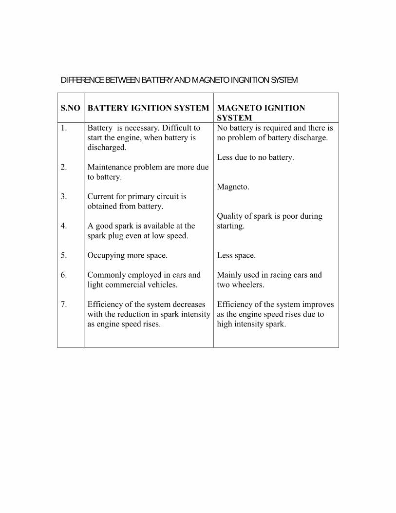
DIFFERENCE BETWEEN BATTERY AND MAGNETO INGNITION SYSTEM
S.NO BATTERY IGNITION SYSTEM MAGNETO IGNITION SYSTEM
1.
2.
3.
4.
5.
6.
7.
Battery is necessary. Difficult to start the engine, when battery is discharged.
Maintenance problem are more due to battery.
Current for primary circuit is obtained from battery.
A good spark is available at the spark plug even at low speed.
Occupying more space.
Commonly employed in cars and light commercial vehicles.
Efficiency of the system decreases with the reduction in spark intensity as engine speed rises.
No battery is required and there is no problem of battery discharge.
Less due to no battery.
Magneto.
Quality of spark is poor during starting.
Less space.
Mainly used in racing cars and two wheelers.
Efficiency of the system improves as the engine speed rises due to high intensity spark.
LUBRICATION-NECESSITY OF LUBRICATION
1. Frictional force between sliding and rotating components like bearings, piston, valve ears etc… so wear and tear occurs.
2. Due to friction , when temperature is so rise seizure of the engine takes place.
3. Large amount of input also required to overcome the friction.
TYPES OF LUBRICATION:
1.FILM OR PERFECT LUBRICATION:
Two rotating parts are completely separated by a thin film of lubricants.
2 .BOUNDARY LUBRICATION:
Not so as above. ie. Incomplete separation.
PURPOSE OF LUBRICATION:
1. To reduce power loss due to friction.2. To minimize wear and tear.3. To provide cooling effect and to remove heat from various parts and
hence seizure of engine is avoided.4. To form an effective seal between piston ring and cylinder walls and thus
escape of gases are prevented and hence power losses are avoided.5. To carry away impurities.6. To provide cushioning effect and hence shock is absorbed and hence
noise level is reduced.
QUALITIES OF LUBRICANTS:
1. Resistance offered by it to the deforming forces.
µoil α 1/Tr when µoil is so decreased due to high temperature. film lubrication is changed into boundary lubrication. In general high loads and large clearances requires high µoil whereas high speed requires low µoil.
2.OILNESS:
Property of an oil to spread and attach itself firmly to the bearings surfaces. In general oiliness should be high to avoid wear and tear.
3 .FILM STRENGTH:
Oil film strength should be high to withstand high loads.
4. FLASH POINT AND FIRE POINT:Minimum temperature of oil at which flash (vapour) is formed .oil burns continuously when flame is brought. In general flash point of oil must high. Always fire point is greater than flash point.
5. VOLATILITY:
Defined by vapourisation of oil at high temperature.
6. STABILITY:
Ability of an oil to resist oxidation. Stability should be high.
7. NON CORROSIVENESS:
Nature of oil.
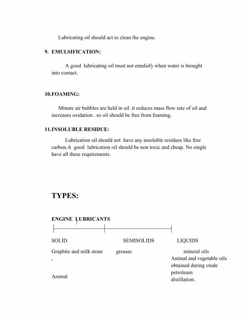
8. DETERGENCY:
Lubricating oil should act to clean the engine.
9. EMULSIFICATION:
A good lubricating oil must not emulsify when water is brought into contact.
10.FOAMING:
Minute air bubbles are held in oil .it reduces mass flow rate of oil and increases oxidation . so oil should be free from foaming.
11.INSOLUBLE RESIDUE:
Lubrication oil should not have any insoluble residues like free carbon.A good lubrication oil should be non toxic and cheap. No single have all these requirements.
TYPES:
ENGINE LUBRICANTS
SOLID SEMISOLIDS LIQUIDS
Graphite and milk stone greases mineral oils ,
Animal
Animal and vegetable oils obtained during crude petroleum distillation.
METHODS OF LUBRICATION:
a) FOR ENGINE BEARINGS:
1) Gravity feed lubrication 2) Wick lubrication 3) Ring lubrication
b) FOR ENGINE PARTS1) Splash lubrication
2) Pressure lubrication 3) Petroil lubrication
FOR ENGINE BEARINGS:
1) GRAVITY FEED LUBRICATION
:
This method is used where the shaft are rotating in stationary bearing.
FOR ENGINE BEARINGS:
GRAVITY FEED LUBRICATION
This method is used where the shaft are rotating in stationary bearing.This method is used where the shaft are rotating in stationary bearing.
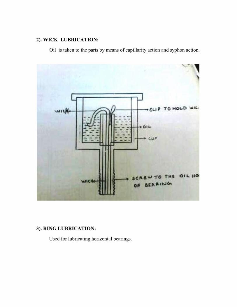
2). WICK LUBRICATION:
Oil is taken to the parts by means of capillarity action and syphon action.
3). RING LUBRICATION:
Used for lubricating horizontal bearings.
2). WICK LUBRICATION:
Oil is taken to the parts by means of capillarity action and syphon action.
3). RING LUBRICATION:
Used for lubricating horizontal bearings.
Oil is taken to the parts by means of capillarity action and syphon action.
FOR ENGINE PARTS
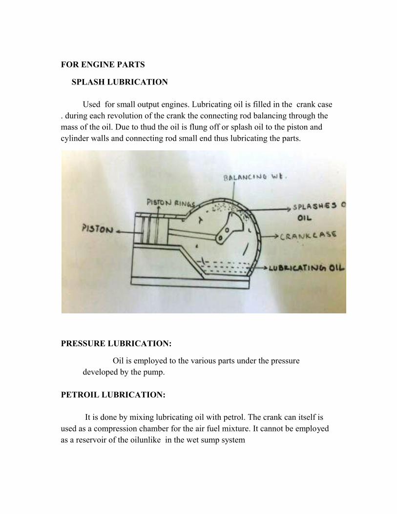
SPLASH LUBRICATION
Used for small output engines. Lubricating oil is filled in the crank case . during each revolution of the crank the connecting rod balancing through the mass of the oil. Due to thud the oil is flung off or splash oil to the piston and cylinder walls and connecting rod small end thus lubricating the parts.
PRESSURE LUBRICATION:
Oil is employed to the various parts under the pressure developed by the pump.
PETROIL LUBRICATION:
It is done by mixing lubricating oil with petrol. The crank can itself is used as a compression chamber for the air fuel mixture. It cannot be employed as a reservoir of the oilunlike in the wet sump system
SPLASH LUBRICATION
Used for small output engines. Lubricating oil is filled in the crank case . during each revolution of the crank the connecting rod balancing through the mass of the oil. Due to thud the oil is flung off or splash oil to the piston and
connecting rod small end thus lubricating the parts.
PRESSURE LUBRICATION:
Oil is employed to the various parts under the pressure developed by the pump.
PETROIL LUBRICATION:
It is done by mixing lubricating oil with petrol. The crank can itself is used as a compression chamber for the air fuel mixture. It cannot be employed as a reservoir of the oilunlike in the wet sump system
Used for small output engines. Lubricating oil is filled in the crank case . during each revolution of the crank the connecting rod balancing through the mass of the oil. Due to thud the oil is flung off or splash oil to the piston and
connecting rod small end thus lubricating the parts.
Oil is employed to the various parts under the pressure
It is done by mixing lubricating oil with petrol. The crank can itself is used as a compression chamber for the air fuel mixture. It cannot be employed
COOLING OF IC ENGINE
NECESSITY OF COOLING :Total heat 100%%B.P 30
%HLCW 30 %HLEG 40 TOTAL 100%
Heat due to combustion in 2500 C .platinum has high melting point melts at 1800 C. so to avoid over heating , cooling is required.
Distortion of the engine components due to high thermal stress set up.
Lubricating oil is broken in the absence of cooling.
Seizure of the components.
Higher temperature, lower efficiency.
PROPERTIES OF EFFICIENT COOLING SYSTEM:
1). Only 30% of heat generated in the combustion chamber should be removed otherwise efficiency is lowered.
2). It should remove heat at a fast rate when engine is hot. During starting of the engine the cooling should be very low.
SYSTEM OF COOLING:
1). AIR COOLING:
Used in motor cycles , scooters , small cars. Circulating fan is also provided. No corrosion as in liquid cooling or clogging of radiator. Simpler , less cost.
DISADVANTAGE:
Non uniform cooling, higher working temperature, have limited size, produce more noise, gives less petrol economy, used for lower output engines.
WATER COOLING:
1)DIRECT OR NON RETURN SYSTEM
Where plenty of water is available. Water is not reused.
2)THERMOSTAT COOLING:
System operating at low speed .so large quantity of water is required.
3)IMPELLER THERMO SYPHON SYSTEM:
Used in automobile cars , bus , heavy trucks.
Flow of water by convection and by using pumps.
When pump fails , thermo syphon takes care.
2)THERMOSTAT COOLING:
System operating at low speed .so large quantity of water is required.
3)IMPELLER THERMO SYPHON SYSTEM:
Used in automobile cars , bus , heavy trucks.
Flow of water by convection and by using pumps.
When pump fails , thermo syphon takes care.
System operating at low speed .so large quantity of water is required.
IMPORTANT COMPONENTS:
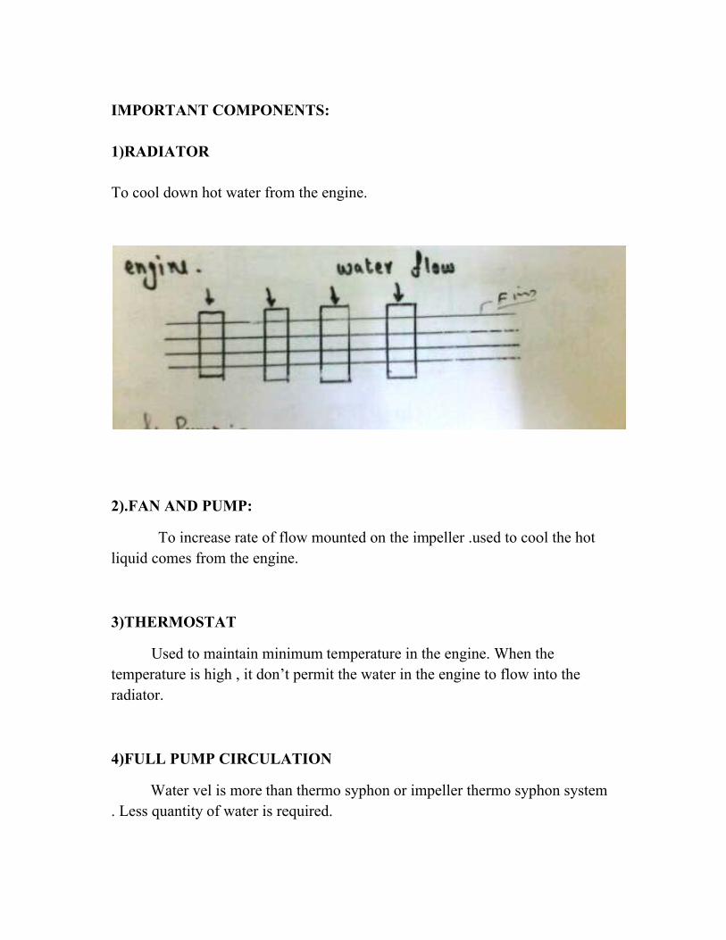
1)RADIATOR
To cool down hot water from the engine.
2).FAN AND PUMP:
To increase rate of flow mounted on the impeller .used to cool the hot liquid comes from the engine.
3)THERMOSTAT
Used to maintain minimum temperature in the engine. When the temperature is high , it don’t permit the water in the engine to flow into the radiator.
4)FULL PUMP CIRCULATION
Water vel is more than thermo syphon. Less quantity of water is required.
IMPORTANT COMPONENTS:
To cool down hot water from the engine.
To increase rate of flow mounted on the impeller .used to cool the hot om the engine.
Used to maintain minimum temperature in the engine. When the temperature is high , it don’t permit the water in the engine to flow into the
4)FULL PUMP CIRCULATION
Water vel is more than thermo syphon or impeller thermo syphon system Less quantity of water is required.
To increase rate of flow mounted on the impeller .used to cool the hot
Used to maintain minimum temperature in the engine. When the temperature is high , it don’t permit the water in the engine to flow into the
or impeller thermo syphon system
EVAPORATIVE COOLING:
Hot vapour from engine after absorbing latent heat flow up gets condensed then flows to the cylinder jackets .
Only 40% water is required ,When compared to other system .
Hence a small radiator is required.
Efficiency is reduced.
DEFECTS IN COOLiNG SYSTEM:
Loss of coolant from the system due to leakage , evaporation.
Over heating of the coolant. Over cooling due to thermostat.