ST T IC SYSTEM CORRECTION WITH ORBIT DETERMINATION OPTION PROD E -LAN I PS WIT UND CONT L POINTS d'Alge, Julio Cesar Lima Bezerra, Paulo Cesar Rego Medeiros Valder Matos de MCT - DA E TECNOLOGIA INPE- INSTITUTO DE PESQUISAS ESPACIAIS Rod. Presidente Dutra, km 40 12630 - Cachoeira Paulista, SP Brazil Commission IV The production of TM-LANDSAT image maps from system corrected images presents the problem of dealing with a positioning error due mainly to innacurate telemetry data broadcasted by the satellite An option to solve this problem is to perform an orbital elements correction through ground control points identified on some scenes of a given orbit. A numerical orbit integrator is then used to generate more accurate ephemeris data over all scenes of the same orbit, which are used for the geometric system correction procedures. 1$ INTROD TI Brazil has many regions not yet covered by the national mapping program The unmapped area reaches about 32% at the scales of 1 :250,000 and 1 :100,000, increasing to 87% at 1:50,000. Considering this situation, it is feasible and even recommendable to use TM-LANDSAT image maps as an alternative to the conventional topographic mapping (Machado e Silva et alii, 1988). Attitude and ephemeris data broadcasted by LANDSAT are used at INPE to produce system corrected images within an internal geometric precision of about 1.5 pixels and a positioning error of around 50 pixels (dBAlge, 1987). This means that at least the positioning error of these images must be reduced to appropriate levels, if they are to be used to generate 1 :250,000 image maps according to internationally adopted cartographic standards. This must be done through an external control, which is normally obtained from existing large scale topographic maps. However, conventional processes used with this aim are practicable only over mapped areas, being unsuitable over unmapped ones. The present work reports the efforts carried by INPE in order to develop an image map generation methodology applicable for both mapped and unmapped regions.
Transcript
ST T
IC SYSTEM CORRECTION WITH ORBIT DETERMINATION OPTION PROD E -LAN I PS
WIT UND CONT L POINTS
d'Alge, Julio Cesar Lima Bezerra, Paulo Cesar Rego Medeiros Valder Matos de
MCT - MINIST~RIO DA CI~NCIA E TECNOLOGIA INPE- INSTITUTO DE PESQUISAS ESPACIAIS Rod. Presidente Dutra, km 40 12630 - Cachoeira Paulista, SP Brazil
Commission IV
The production of TM-LANDSAT image maps from system corrected images presents the problem of dealing with a positioning error due mainly to innacurate telemetry data broadcasted by the satellite An option to solve this problem is to perform an orbital elements correction through ground control points identified on some scenes of a given orbit. A numerical orbit integrator is then used to generate more accurate ephemeris data over all scenes of the same orbit, which are used for the geometric system correction procedures.
1$ INTROD TI
Brazil has many regions not yet covered by the national mapping program The unmapped area reaches about 32% at the scales of 1 :250,000 and 1 :100,000, increasing to 87% at 1:50,000. Considering this situation, it is feasible and even recommendable to use TM-LANDSAT image maps as an alternative to the conventional topographic mapping (Machado e Silva et alii, 1988).
Attitude and ephemeris data broadcasted by LANDSAT are used at INPE to produce system corrected images within an internal geometric precision of about 1.5 pixels and a positioning error of around 50 pixels (dBAlge, 1987).
This means that at least the positioning error of these images must be reduced to appropriate levels, if they are to be used to generate 1 :250,000 image maps according to internationally adopted cartographic standards. This must be done through an external control, which is normally obtained from existing large scale topographic maps. However, conventional processes used with this aim are practicable only over mapped areas, being unsuitable over unmapped ones.
The present work reports the efforts carried by INPE in order to develop an image map generation methodology applicable for both mapped and unmapped regions.
2. THO LOGY
First of all it is necessary to choose, for a given orbit, a set of well distributed ground control points, from which accurate projection coordinates are known.
The orbit correction process is based on the identification of these ground control points in some images along the selected orbit. Nevertheless, a reliable identification is not possible with raw images, being necessary to use Level 0 images to this end. This preprocessing level comprises a radiometric equalization and an along line resampling corresponding to the correction of mirror profile/line length, sensor delay and Earth rotation effects.
Therefore, image coordinates are initially read from Level 0 digital images; subsequently, they are converted into raw image coordinates, from which projection coordinates can be obtained by applying the photogrammetric model adopted for system geometric corrections (Serra, 1984).
The orbit correction itself corresponds to the estimation of an optimal value for a state vector expressing inertial satellite position and velocity at a reference time to. Prior to the correction process, all the acquisition times of pixels related to ground control points are sorted on ascending (or descending) order, to being selected as the first of them. The optimal state, and so the corrected orbit, is computed through a numerical least squares approach, from the comparison between true and calculated projection coordinates of control points (Medeiros et alii, 1988). The approach is iterative and, at each step, the ephemeris data necessary to calculate projection coordinates through the photogrammetric model are obtained from the reference state vector through numerical orbit integration.
When a final reference state vector is reached, the same orbit integrator is used to generate corrected ephemeris data, which are applied in conjunction with system correction procedures to produce images with improved geodetic accuracy.
3. TESTS D RESULTS
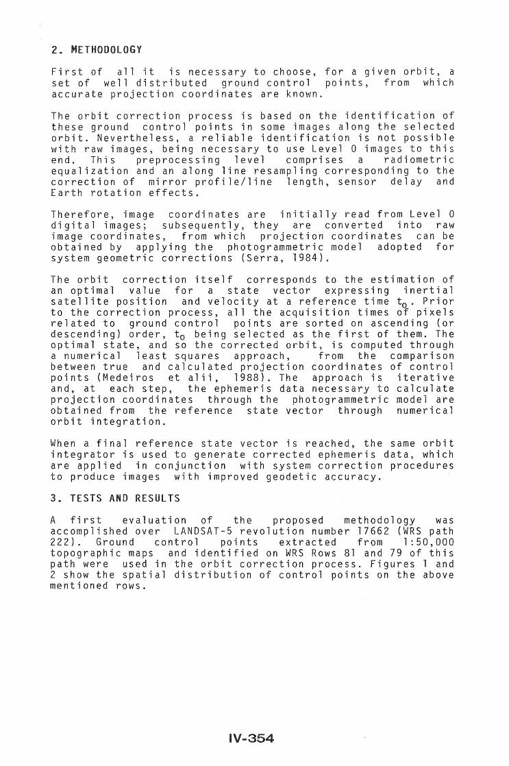
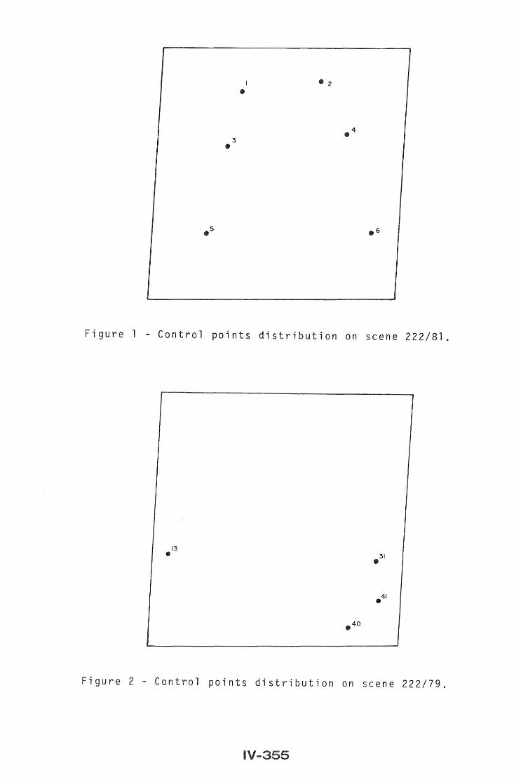
A first evaluation of the proposed methodology was accomplished over LANDSAT-5 revolution number 17662 (WRS path 222). Ground control points extracted from 1:50,000 topographic maps and identified on WRS Rows 81 and 79 of this path were used in the orbit correction process. Figures 1 and 2 show the spatial distribution of control points on the above mentioned rows.
:3
•
1
• • 2
Figure 1 - Control points distribution on scene 222/81.
13 • 31 •
Figure 2 - Control points distribution on scene 222/79.
Each of these control points sets was determined after successive internal geometric quality evaluations over the corresponding images, which enabled the detection of outliers. As a result of this minimum quality control criterion, it was not possible to achieve an ideal situation either in terms of spatial distribution or in quantity.
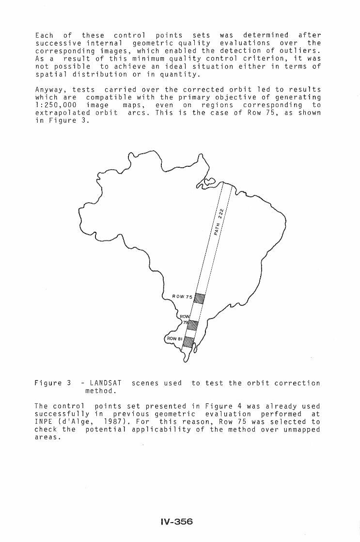
Anyway, tests carried over the corrected orbit led to results which are compatible with the primary objective of generating 1:250,000 lmage maps, even on regions corresponding to extrapolated orbit arcs. This is the case of Row 75, as shown in Figure 3.
Figure 3 - LANDSAT scenes used to test the orbit correction method.
The control points set presented in Figure 4 was already used successfully in previous geometric evaluation performed at INPE (d'Alge, 1987). For this reason, Row 75 was selected to check the potential applicability of the method over unmapped areas.
, 8 1 84
83
8 2
8 9
88 868 7 10
8
8 11 812 .16
817
13 8 15
8
8 18 819
822
820 8 21
8 24
825
026 821
Figure 4 - Control points distribution on Quadrant B of scene 222/75.
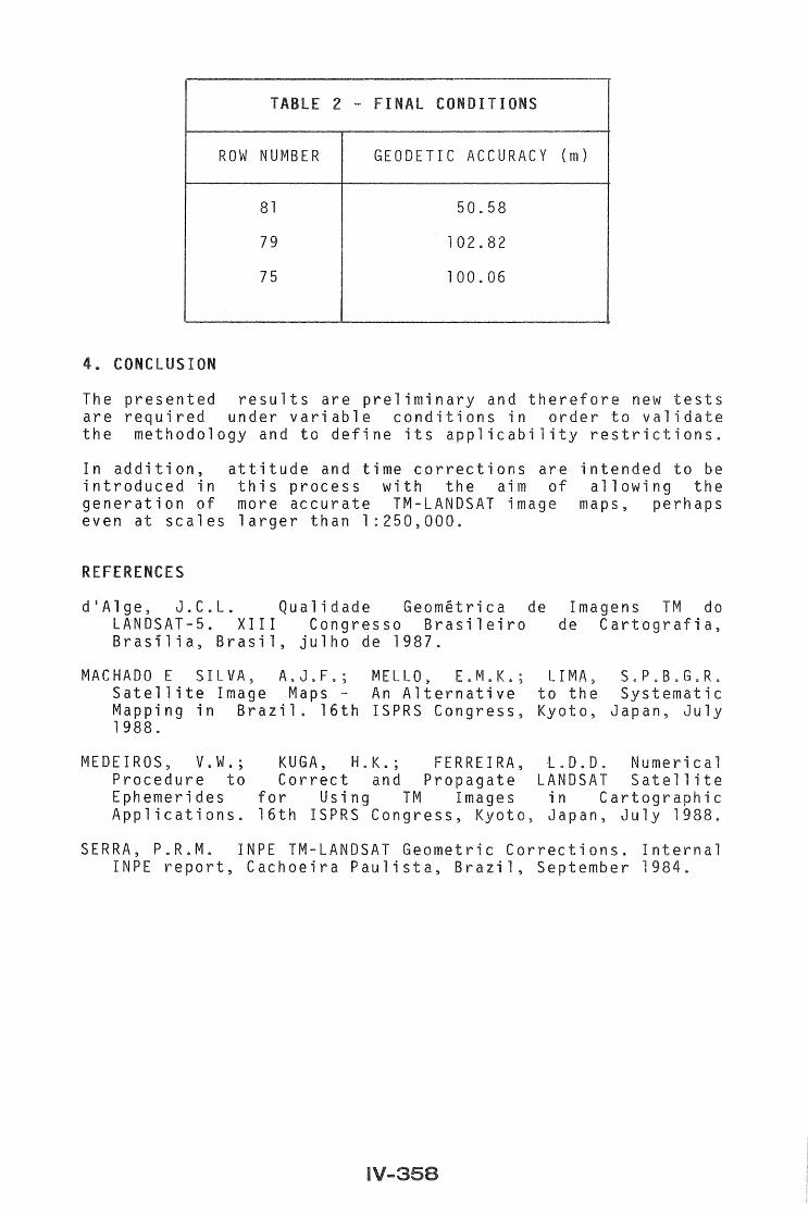
The geodetic accuracies of scenes 81, 79 and 75 were estimated and the corresponding values before and after the execution of the orbit correction procedure are presented on Tables 1 and 2, respectively.
TABLE 1 - START CONDITIONS
ROW NUMBER GEODETIC ACCURACY (m)
81 1602.11
79 1610.98
75 1605.18
LE 2 - FIN CONDITIONS
ROW NUMBER GEODETIC ACCURACY ( m )
81 50.58
79 102.82
75 100.06
4. CONCLUSION
The presented results are preliminary and therefore new tests are required under variable conditions in order to validate the methodology and to define its applicability restrictions
In addition, attitude and time corrections are intended to be introduced in this process with the aim of allowing the generation of more accurate TM-LANDSAT image maps, perhaps even at scales larger than 1 :250,000.
RE RENCES
d'Alge, J.C.L. Qualidade Geometrica de LANDSAT-5. XIII Congresso Brasileiro Brasilia, Brasil, julho de 1987.
Imagens TM do de Cartografia,
MACHADO E SILVA, A.J.F.; MELLO, E.M.K.; LIMA, S.P.B.G R. Satellite Image Maps - An Alternative to the Systematic Mapping in Brazil. 16th ISPRS Congress, Kyoto, Japan, July 1988.
MEDEIROS, V.W.; KUGA, H.K.; FERREIRA, t.D.D. Numerical Procedure to Correct and Propagate LANDSAT Satellite Ephemerides for Using TM Images in Cartographic Applications. 16th ISPRS Congress, Kyoto, Japan, July 1988.
Tiina Kilpelainen Department of Photogrammetry The Royal Institute of ~~~~~~
S-100 44 Stockholm, SWEDEN Commission III/IV
Raster scanning is an automatic digitising method used in data extraction from line maps in large scales" This deals with the problems in automatic recognition of complicated objects based on vectorized map data.
In order to treat the problem of automatic object recognition systematically, the cartographic language must be strictly formalized. The first part of this paper describes a theoretical model for large scale maps" The model is tested with objects "building". A manual test is made to recognize all the buildings on map sheets in scale 1: 2000 with the rules, composed according to the model. The result gave 100% of buildings classified with 1-9% errors of commission depending on the type of map information.
The second part of this paper discusses the problems when trying to implement the presented rules in Turbo Prolog running on IBM PC. The main problem lies - not the difficulty to program the rules but the di to update all the possible situations and to organize input data properly.
1. INTRODUCTION
A lot of efforts have been involved in automatic recognititon of symbols.. The classical way to perform symbol recognition has been to train the system for the classification task under consideration and find the relevant probability density function for each symbol class. Norwegian Computing Center reports results with up to 99% correct classified handwritten letters, (Holbaek-Hanssen et al., 1986). Weber points out that there are several companies which offer software for symbol recognition without giving details about the underlying method and results (Weber, 1987)" It seems quite clear anyhow that recognition of numbers, letters and point symbols have a rather long and successful tradition, while recognition of map objects based on vectorized data still lies on its early ages.
De Simone reports a success rate of 90% with 1% error in automatic recognition of railways, roads and landparcels, (De Simone, 1986)" He uses the combination of the geometrical/ statistical and the relational method for recognition, (Weber, 1987). The check of neighborhood relation of the reclassified candidates determines if these are refused or accepted into the class in question (e.g., the adjacent polygons of a
cons map reading abilities pointed out ..
the model at the the model as far
In symbol's real boundary
An
come
on , streets and real
treated in this work refer to
2.2 Perceptual background
A map shows a s mapreader
visual and raster ( the visual variables 1 other hand of contrasts, and ect's their relat transformed to reality. to other be taken classi
= relationship An information quantity is built up by messages and relationships in different levels.
and the elementary messages can have a line can have values linewidth 0.25 mm
and linestyle
3. PROCEDURE FOR THE MANUAL EXPERIMENT
3.1 Assumptions
The natural way to build up the hierarchy for the model is from elementary messages to messages of higher level. Therefore I assume that the mapreading takes place from detailed observations to an overview. I work only on level 1 and 2 and thus do not consider overview observations presently.
Here I 1 the experiment on vectorized large scale mapdata. I assume the following information is already recognized based on section 1,,:
- vectors(start- and endpoints, linestyle(width,style» - characters and strings of characters - symbols - arcs
The objects on the edges of the mapsheets are not considered in experiment, neither contour lines.
rules were made with different degrees of to describe the object "building" according to the
presented model. The for building up the rules is formed by perceptual observations. Some detailed conditions have their origin in (the Handbook for Detailsurveying from the city of Stockholm, 1978), e.g. the linewidth for the outlines of houses.. The rules were matched manually with all the buildings on three different base mapsheets in scale 1: 2 000, from the city of Stockholm. The maporiginals have been produced
from the of
The
the
scale 1:400"
success rate to match
next
model
have been produced
was for the different rules. I and to the given rule. In
the rule was improved with additional took account perceptual matters.
complexity, lower complexity. I will and then separate it in
according to the
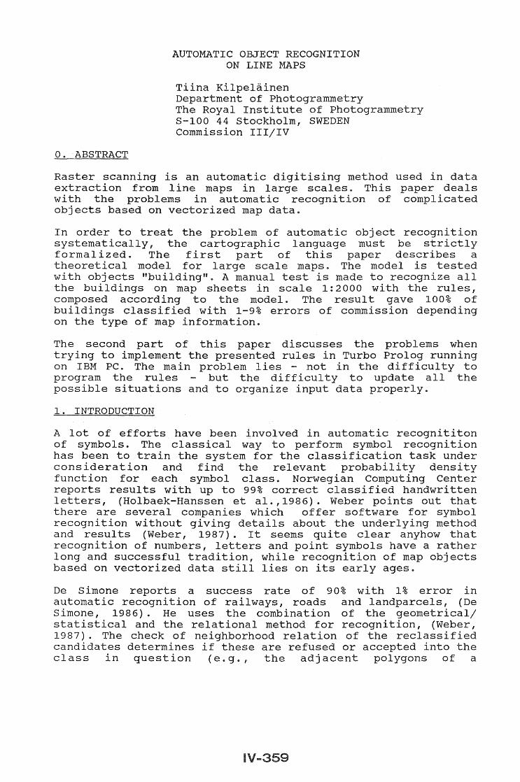
A a closed solid I with linewidth scale 1:400). It is not required that it has corners as shown in figur 2. Besides straight
can consist of arcs.
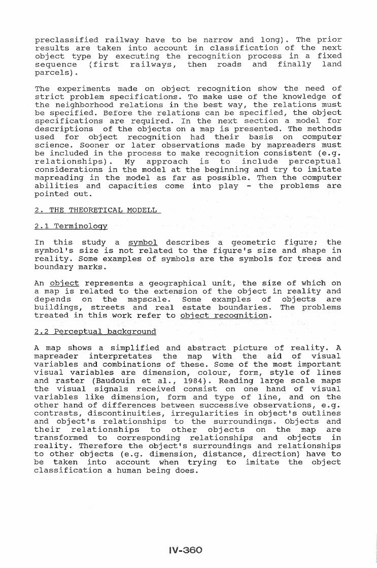
It of
in be read as one,
It the are the
can I
1 ..
None of the outl
and
or
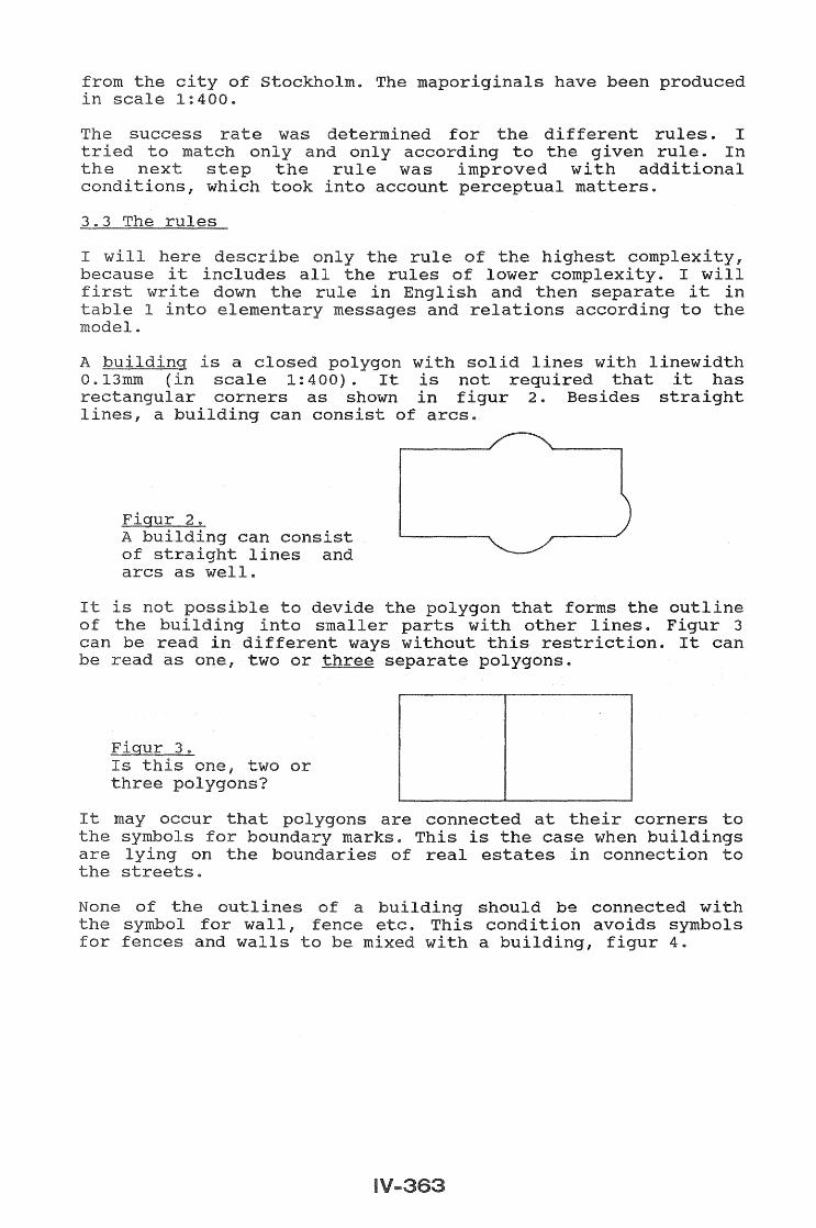
the wall, fence for fences and s to be
polygon that forms the outline parts with lines. Figur 3 without this restriction. It can
separate polygons.
connected at their corners to the case when buildings
estates in connection to
should be connected with condition avoids symbols
with a building, figur 4.
Figur 4. Symbols for can be mixed with the outlines of buildings ..
//
//
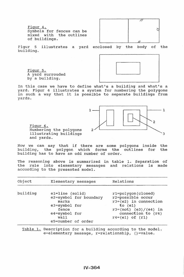
Figur 5 building ..
a yard enclosed by the body of the
In this case we have to define what's a building and what's a yard. Figur 6 illustrates a system for numbering the polygons in such a that possible to separate buildings from yards ..
1
Figur 6 .. Numbering the polygons 2
buildings and yards ..
Now we can say that if there are some polygons inside the building, the polygon which forms the outlines for the building has to have an odd number of order ..
The reasoning above is summarized in table l" Separation of the elementary messages and made according to the model.
Object
building
Elementary messages
el=line (solid) e2=symbol for boundary
marks e3=symbol for
fence e4=symbol for
wall e5=number of order
rl=polygon(closed) r2=possible occur r3=(e2) in connection
to (el) r3= (not) (e3) / (e4) in
connection to (r4) r4=(el) of (rl)
for a building according to the model. e=elementary message, r=relationship, ()=value.
to not of
It E.g. bui we can take them
than 25 of
.. However,
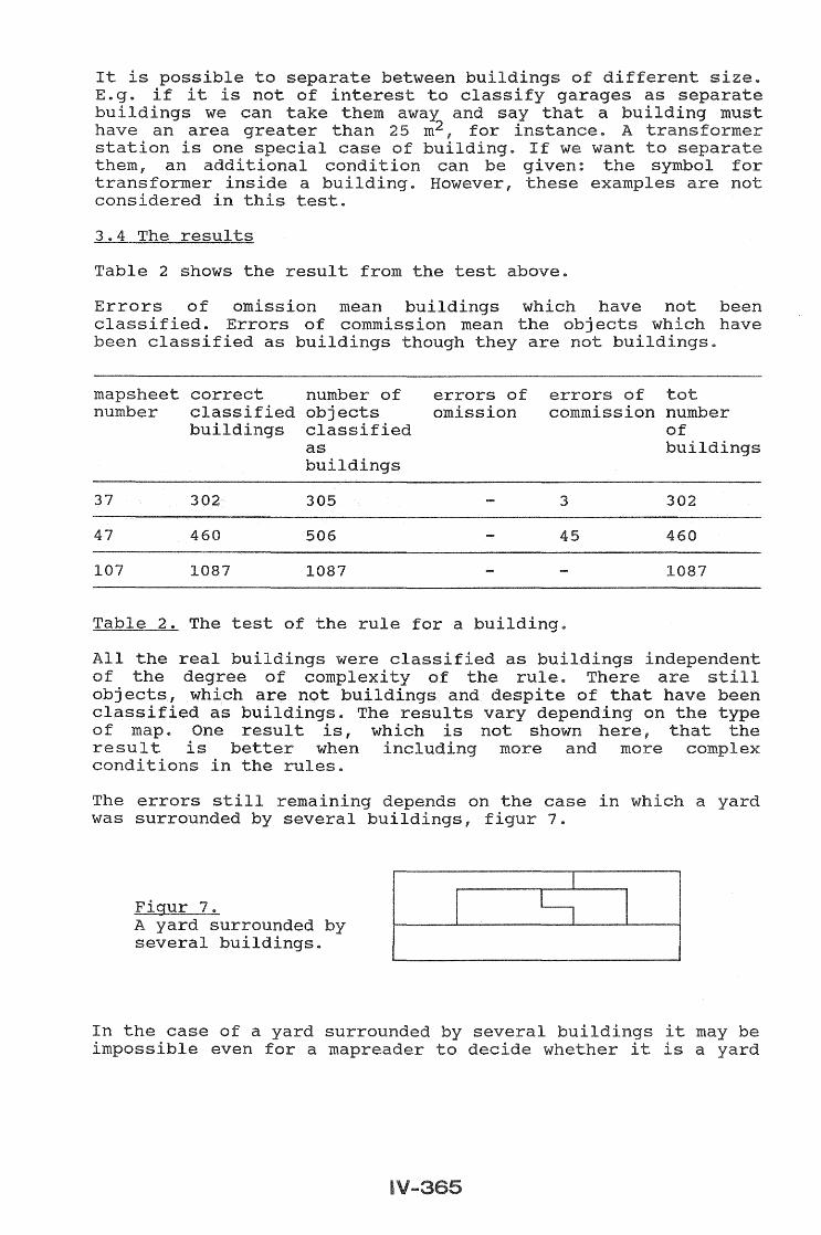
Table 2 shows the from the test above.
Errors of have not been class Errors of have been as buildings are
map sheet correct number of objects classi
errors of omiss
errors of tot number
37 302
47 460
107 1087
The
All the of the objects, classified as
as buildings
305
506
1087
of the rule for a
were of complexity
are not buildings and buildings The results
3
45
of One result is, which is not shown here, result is when more and more
the rules ..
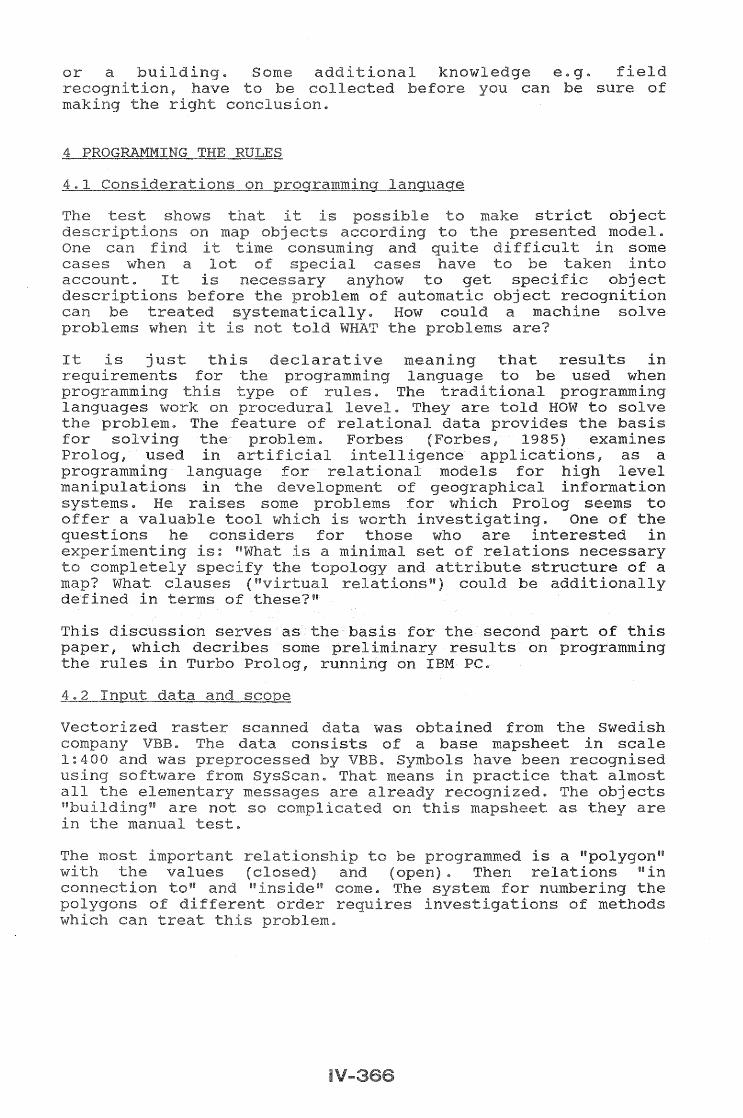
The errors was surrounded
I remaining depends on the case several 7 ..
I
I buildings"
In the case of a several even whether
I
number of
302
460
1087
the
a
"g iel
results be used when
some common separate recurs
checked
The restriction to be processed
this part linepredicates offer which has several a well known other PC attack the problem the areas similar problem to the problem of way to out the and program capabil have
One recursion.. Prolog uses all the alternative proofs of There are techniques, called only one answer of with the placement of ncut u
recurs 0 The this paper seems to be the space .. for PC are
One encountered used e The rules
factor ..
more a here
and not a
of the Turbo other for
the
level of
of stack
be handled on
I 1984 .. Me, (1986) I
for Carto London, vol
Forbes, Re, (1985), GIS: Toward the 5th meeting ASP,