EC6611 COMPUTER NETWORKS LAB VVIT DEPARTMENT OF ELECTRONICS AND COMMUNICATION ENGINEERING Dharmapuri – 636 703 Regulation : 2013 Branch : B.E. – ECE Year & Semester : III Year / VI Semester ICAL ENG LAB MANUAL EC6611- COMPUTER NETWORKS LABORATORY
Transcript
EC6611 COMPUTER NETWORKS LAB
VVIT DEPARTMENT OF ELECTRONICS AND COMMUNICATION ENGINEERING
Dharmapuri – 636 703
Regulation : 2013
Branch : B.E. – ECE
Year & Semester : III Year / VI Semester
ICAL ENG
LAB MANUAL
EC6611- COMPUTER NETWORKS LABORATORY
EC6611 COMPUTER NETWORKS LAB
VVIT DEPARTMENT OF ELECTRONICS AND COMMUNICATION ENGINEERING
ANNA UNIVERSITY CHENNAI
REGULATION - 2013
EC6611- COMPUTER NETWORKS LABORATORY
1. Implementation of Error Detection / Error Correction Techniques
2. Implementation of Stop and Wait Protocol and sliding window
3. Implementation and study of Go back-N and selective repeat protocols
4. Implementation of High Level Data Link Control
5. Study of Socket Programming and Client – Server model
6. Write a socket Program for Echo/Ping/Talk commands.
7. To create scenario and study the performance of network with CSMA / CA Protocol
and compare with CSMA/CD protocols.
8. Network Topology - Star, Bus, Ring
9. Implementation of distance vector routing algorithm
10. Implementation of Link state routing algorithm
11. Study of Network simulator (NS) and simulation of Congestion Control Algorithms
Using NS
12. Encryption and decryption.
TOTAL : 45 PERIODS
EC6611 COMPUTER NETWORKS LAB
VVIT DEPARTMENT OF ELECTRONICS AND COMMUNICATION ENGINEERING
INDEX
EX.NO DATE LIST OF EXPERIMENTSSTAFF
SIGINATURE REMARKS
1 Implementation of Error Detection / ErrorCorrection Technique
2 Implementation of Stop and Wait Protocol
3 Implementation of Sliding Window Go Back N
4 Implementation and study of sliding windowSelective repeat protocol.
5 Study of Socket Programming And Client –Server Model
6 Write a Socket Program for Echo Commands
7 Write a Socket Program for Ping Commands
8 Write a Socket Program for Talk Commands
9 Implementation of Distance Vector RoutingAlgorithm
10 Implementation of Link State RoutingAlgorithm
11 Implementation and Study the Performance of
Network with CSMA / CA Protocol
12 Implementation and Study the Performance of
Network With CSMA/CD Protocols
13
Implementation of Data Encryption and
Decryption
14
Study of Network Simulator (Ns) and
Simulation of Congestion Control Algorithms
Using NS
15 Network Topology - Token Bus
16 Network Topology - Token Ring
17 Implementation of High Level Data LinkControl
EC6611 COMPUTER NETWORKS LAB
VVIT DEPARTMENT OF ELECTRONICS AND COMMUNICATION ENGINEERING
INTRODUCTION
COMPUTER NETWORKS LABORATORY
A computer network is an interconnection of various computers to share software, hardware,
resources and data through a communication medium between them. A Computer Networking is a set
of autonomous computers that permits distributed processing of the information and data and increased
Communication of resources .Any Computer Networking communication need a sender, a receiver and
a communication medium to transfer signal or Data from sender to the receiver. We need sender,
receiver, communication channel, protocols and operating system to establish a computer networking.
A networks model describes the organization of various computers in a network for using resources.
A computer networks communication can be based on centralized, distributed or collaborative
computing. Centralized computing involves many workstations or terminals, connected to one central
mainframe or other powerful computer. Distributed computing interconnects one or more personal
computers and allows various services like Data sharing, hardware sharing resources sharing or
network sharing. The collaborative computing is the combination of centralized and distributed
computing.
1. Centralized computing.
• It is also known as client-server computing.
• In this type of system, multiple computers are joined to one powerful mainframe computer.
• The server or mainframe computer has huge storage and processing capabilities.
• The computers that are connected to the mainframe or server are called Clients or Nodes.
• These nodes are not connected to each other; they are only connected to server.
2. Distributed computing
• If one computer can forcibly start, stop or control another computers are not autonomous. A
system with one control unit and many slaves, or a large computer with remote printers and a
terminal is not called a computer network; it is called a Distributed System.
• Distributed computing means that the task is divided among multiple computers.
• Distributed computing interconnects one or more personal computers or Workstations.
• In distributed computing, the nodes are capable of processing their own data and rely on
network for services other than data processing.
• It allows various services like network sharing, hardware sharing and file sharing.
EC6611 COMPUTER NETWORKS LAB
VVIT DEPARTMENT OF ELECTRONICS AND COMMUNICATION ENGINEERING
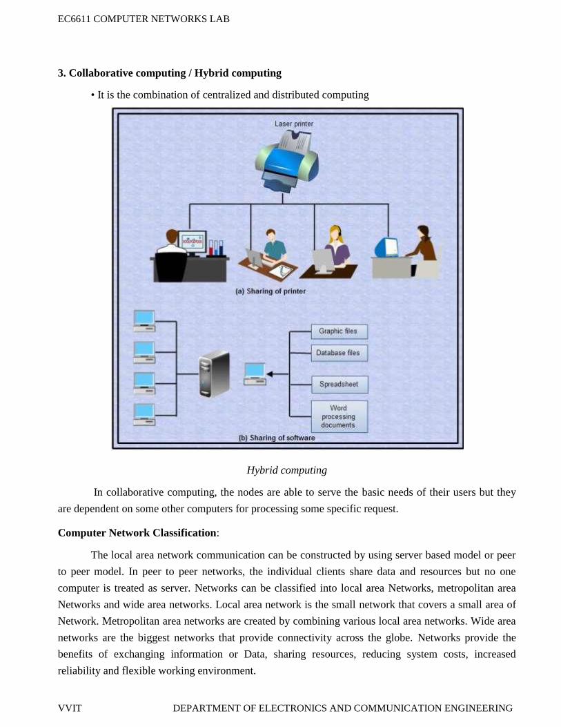
3. Collaborative computing / Hybrid computing
• It is the combination of centralized and distributed computing
Hybrid computing
In collaborative computing, the nodes are able to serve the basic needs of their users but they
are dependent on some other computers for processing some specific request.
Computer Network Classification:
The local area network communication can be constructed by using server based model or peer
to peer model. In peer to peer networks, the individual clients share data and resources but no one
computer is treated as server. Networks can be classified into local area Networks, metropolitan area
Networks and wide area networks. Local area network is the small network that covers a small area of
Network. Metropolitan area networks are created by combining various local area networks. Wide area
networks are the biggest networks that provide connectivity across the globe. Networks provide the
benefits of exchanging information or Data, sharing resources, reducing system costs, increased
reliability and flexible working environment.
EC6611 COMPUTER NETWORKS LAB
VVIT DEPARTMENT OF ELECTRONICS AND COMMUNICATION ENGINEERING
Computer Network topology:
The physical arrangement of computers in a communication network is called as topology. In
star topology, every system on the network is connected to a central controller called Hub and all the
data is transmitted through this. Star topology is very easy to install and configure. In bus topology, a
single cable acts as a backbone of the communication network and all the nodes or computers are
attached to it by using T connectors.
Uses of Computer Networks:
The computer networks are playing an important role in providing services to large
organizations as well as to the individual common man.
Service Provided by the Network for Companies:
• Many organizations have a large number of computers in operation. These computers may bewithin the same building, campus, city or different cities.
• Even though the computers are located in different locations, the organizations want to keep
track of inventories, monitor productivity, do the ordering and billing etc.
• The computer networks are useful to the organizations in the following ways:
1. Resource sharing.
2. For providing high reliability.
3. To save money.
4. It can provide a powerful communication medium.
EC6611 COMPUTER NETWORKS LAB
VVIT DEPARTMENT OF ELECTRONICS AND COMMUNICATION ENGINEERING
1. Resource sharing
• It allows all programs, equipments and data available to anyone on the network irrespective ofthe physical location of the resource and the user.
Resource sharing
2. High reliability due to alternative sources of data:
• It provides high reliability by having alternative sources of data. For e.g. all files could bereplicated on more than one machines, so if one of them is unavailable due to hardware failure
or any other reason, the other copies can be used.
• The aspect of high reliability is very important for military, banking, air traffic control, nuclearreactor safety and many other applications where continuous operations is a must even if there
are hardware or software failures.
3. Money saving:
• Computer networking is an important financial aspect for organizations because it savesmoney.
• Organizations can use separate personal computer one per user instead of using mainframe
computer which are expensive.
• The organizations can use the workgroup model (peer to peer) in which all the PCs arenetworked together and each one can have the access to the other for communicating or sharing
purpose.
• The organization, if it wants security for its operation it can go in for the domain model inwhich there is a server and clients. All the clients can communicate and access data through the
server.
EC6611 COMPUTER NETWORKS LAB
VVIT DEPARTMENT OF ELECTRONICS AND COMMUNICATION ENGINEERING
CLIENT - SERVER BLOCK MODEL:
Client -Server
Client: The individual workstations in the network are called as clients.
Server: The central computer which is more powerful than the clients and which allows the
clients to access its software and database is called as the server.
• Server computers typically are more powerful than client computers or are optimized to
function as servers.
• The whole arrangement is called as client -server model.
EC6611 COMPUTER NETWORKS LAB
VVIT DEPARTMENT OF ELECTRONICS AND COMMUNICATION ENGINEERING
EX.NO:1
DATE:
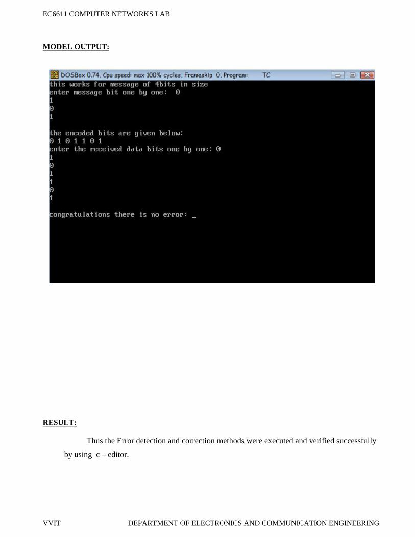
AIM:Write a program for error detection and error correction techniques by Hamming Method using
C language.
APPARATUS REQUIERD:
C -editor
Standalone desktop.
PROCEDURE:
1. Start the program.
2. Open C-editor.
3. Type the C program.
4. Save the program with file name ext .c
5. Run the program.
6. If any error occurs in the program correct the error and run it again.
7. Enter the data of 4 bit size message bit.
8. Check the entered data.
9. Stop the program.
IMPLEMENTATION OF ERROR DETECTION / ERROR CORRECTION TECHNIQUES
EC6611 COMPUTER NETWORKS LAB
VVIT DEPARTMENT OF ELECTRONICS AND COMMUNICATION ENGINEERING
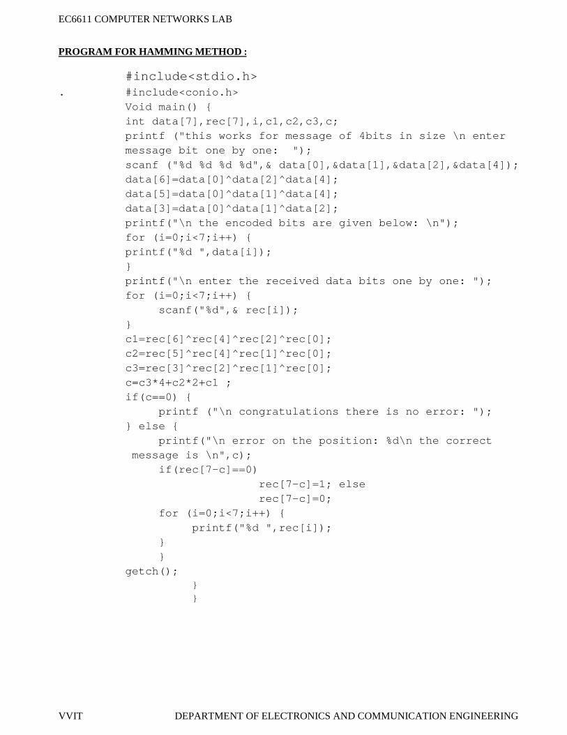
PROGRAM FOR HAMMING METHOD :
#include<stdio.h>. #include<conio.h>
Void main() {int data[7],rec[7],i,c1,c2,c3,c;printf ("this works for message of 4bits in size \n entermessage bit one by one: ");scanf ("%d %d %d %d",& data[0],&data[1],&data[2],&data[4]);data[6]=data[0]^data[2]^data[4];data[5]=data[0]^data[1]^data[4];data[3]=data[0]^data[1]^data[2];printf("\n the encoded bits are given below: \n");for (i=0;i<7;i++) {printf("%d ",data[i]);}printf("\n enter the received data bits one by one: ");for (i=0;i<7;i++) {
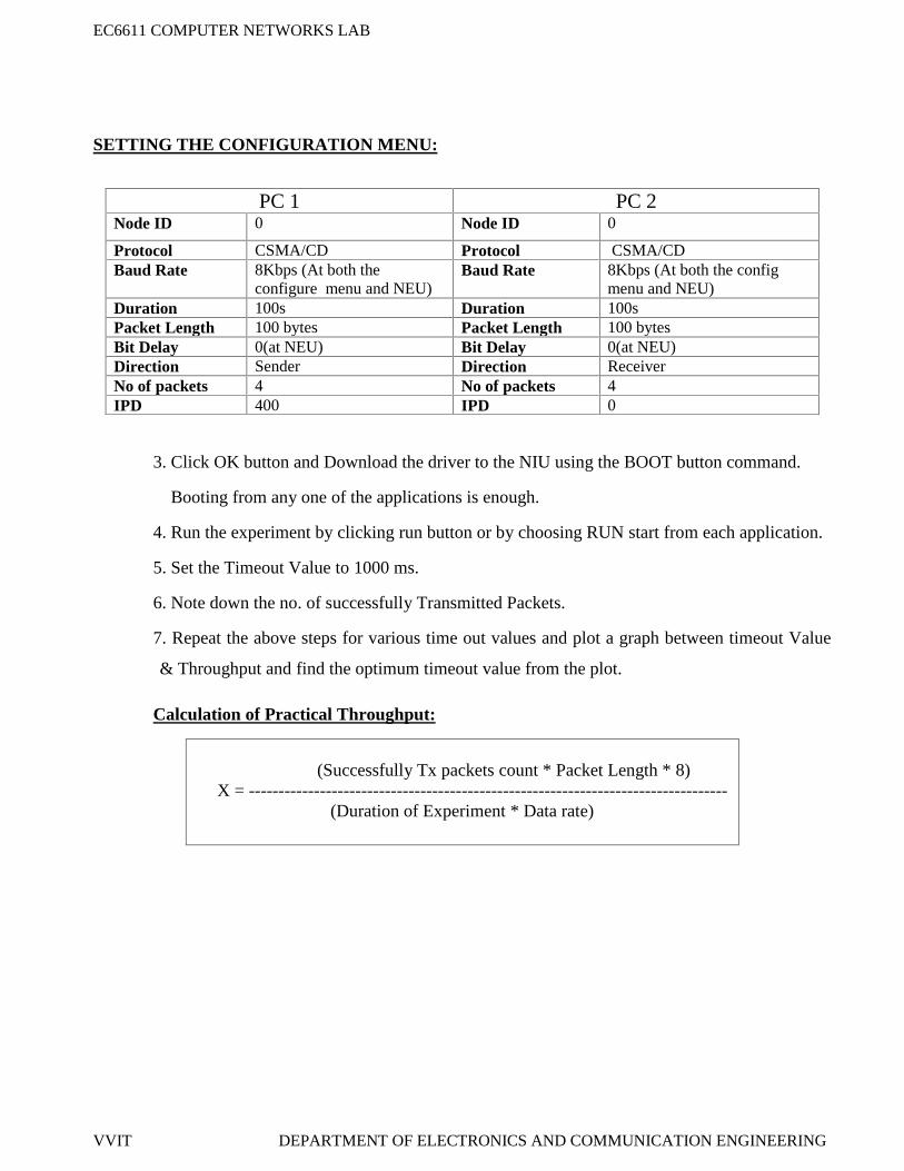
Protocol CSMA/CD Protocol CSMA/CDBaud Rate 8Kbps (At both the
configure menu and NEU)Baud Rate 8Kbps (At both the config
menu and NEU)Duration 100s Duration 100sPacket Length 100 bytes Packet Length 100 bytesBit Delay 0(at NEU) Bit Delay 0(at NEU)Direction Sender Direction ReceiverNo of packets 4 No of packets 4IPD 400 IPD 0
EC6611 COMPUTER NETWORKS LAB
VVIT DEPARTMENT OF ELECTRONICS AND COMMUNICATION ENGINEERING
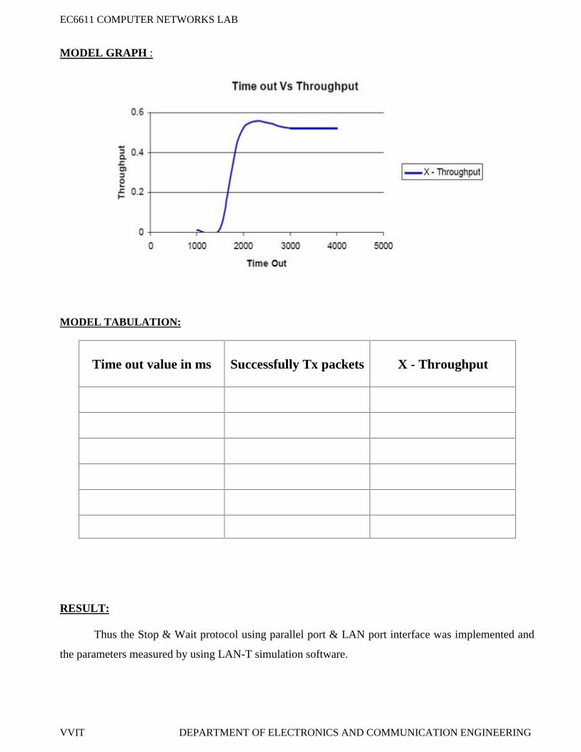
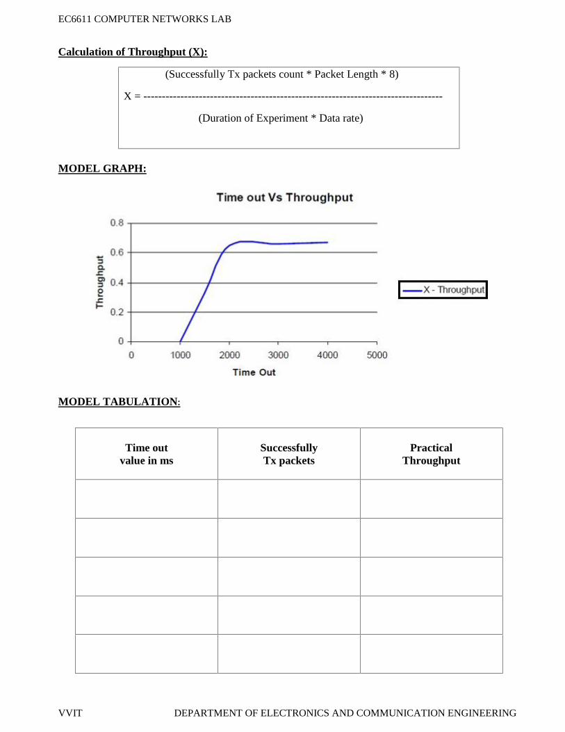
MODEL GRAPH :
MODEL TABULATION:
Time outvalue in ms
SuccessfullyTx packets
PracticalThroughput
RESULT:
Thus the sliding window selective repeat protocol for data transfer between two nodes over an
unreliable network through parallel port & LAN port interface was implemented and studied by using
LAN-T simulation software.
EC6611 COMPUTER NETWORKS LAB
VVIT DEPARTMENT OF ELECTRONICS AND COMMUNICATION ENGINEERING
EX.NO:5
DATE:
STUDY OF SOCKET PROGRAMMING AND CLIENT – SERVER MODEL
AIM:
To write a program and study of socket programming and client – server based model by using
JDK tool kit software.
APPARATUS REQUIERD:
Personal computer
JDK Tool kit 5.0
PROCEDURE:
Server:
Create a server socket and bind it to port.
Listen for new connection and when a connection arrives, accept it.
Send server‟s date and time to the client.
Read client‟s IP address sent by the client.
Display the client details.
Repeat steps 2-5 until the server is terminated.
Close all streams.
Close the server socket.
Stop.
Client: Create a client socket and connect it to the server‟s port number.
Retrieve its own IP address using built-in function.
Send its address to the server.
Display the date & time sent by the server.
Close the input and output streams.
Close the client socket.
Stop.
EC6611 COMPUTER NETWORKS LAB
VVIT DEPARTMENT OF ELECTRONICS AND COMMUNICATION ENGINEERING
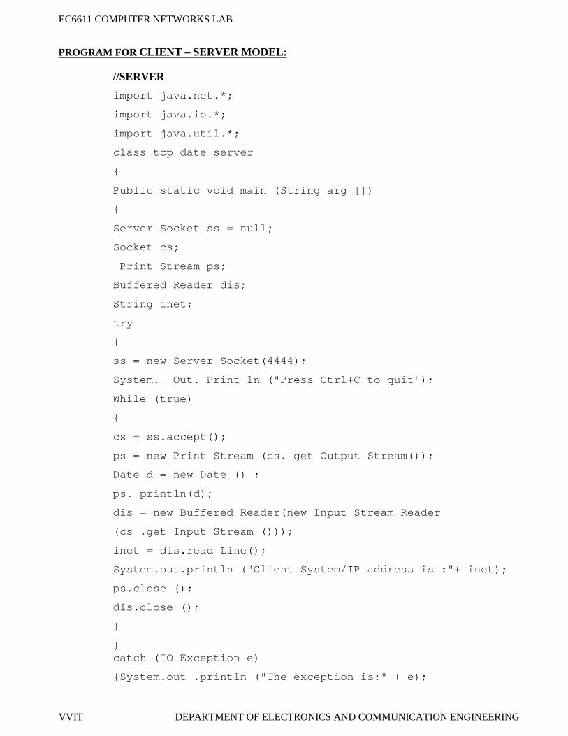
PROGRAM FOR CLIENT – SERVER MODEL:
//SERVER
import java.net.*;
import java.io.*;
import java.util.*;
class tcp date server
{
Public static void main (String arg [])
{
Server Socket ss = null;
Socket cs;
Print Stream ps;
Buffered Reader dis;
String inet;
try
{
ss = new Server Socket(4444);
System. Out. Print ln ("Press Ctrl+C to quit");
While (true)
{
cs = ss.accept();
ps = new Print Stream (cs. get Output Stream());
Date d = new Date () ;
ps. println(d);
dis = new Buffered Reader(new Input Stream Reader
(cs .get Input Stream ()));
inet = dis.read Line();
System.out.println ("Client System/IP address is :"+ inet);
ps.close ();
dis.close ();
}
}catch (IO Exception e)
{System.out .println ("The exception is:" + e);
EC6611 COMPUTER NETWORKS LAB
VVIT DEPARTMENT OF ELECTRONICS AND COMMUNICATION ENGINEERING
}
}
}
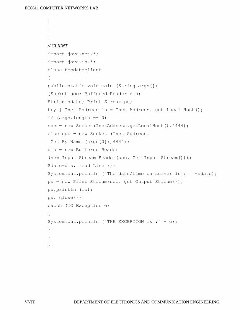
// CLIENT
import java.net.*;
import java.io.*;
class tcpdateclient
{
public static void main (String args[])
{Socket soc; Buffered Reader dis;
String sdate; Print Stream ps;
try { Inet Address is = Inet Address. get Local Host();
if (args.length == 0)
soc = new Socket(InetAddress.getLocalHost(),4444);
else soc = new Socket (Inet Address.
Get By Name (args[0]),4444);
dis = new Buffered Reader
(new Input Stream Reader(soc. Get Input Stream()));
Sdate=dis. read Line ();
System.out.println ("The date/time on server is : " +sdate);
ps = new Print Stream(soc. get Output Stream());
ps.println (is);
ps. close();
catch (IO Exception e)
{
System.out.println ("THE EXCEPTION is :" + e);
}
}
}
EC6611 COMPUTER NETWORKS LAB
VVIT DEPARTMENT OF ELECTRONICS AND COMMUNICATION ENGINEERING
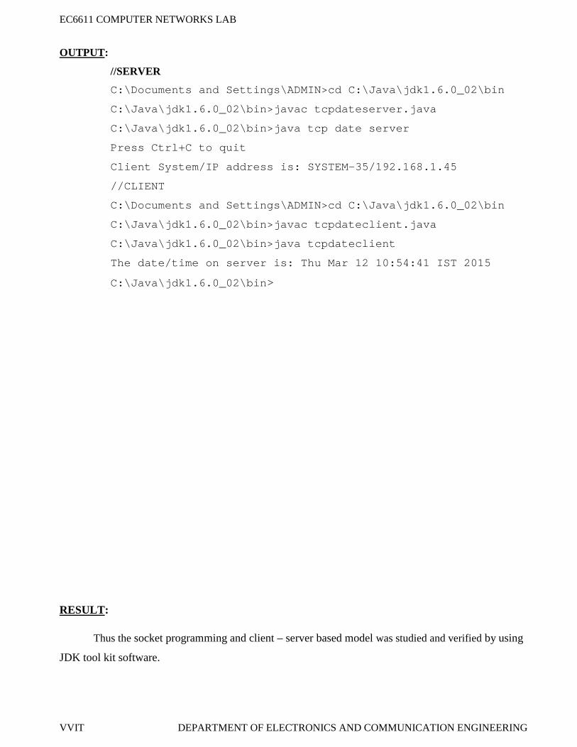
OUTPUT:
//SERVER
C:\Documents and Settings\ADMIN>cd C:\Java\jdk1.6.0_02\bin
C:\Java\jdk1.6.0_02\bin>javac tcpdateserver.java
C:\Java\jdk1.6.0_02\bin>java tcp date server
Press Ctrl+C to quit
Client System/IP address is: SYSTEM-35/192.168.1.45
//CLIENT
C:\Documents and Settings\ADMIN>cd C:\Java\jdk1.6.0_02\bin
C:\Java\jdk1.6.0_02\bin>javac tcpdateclient.java
C:\Java\jdk1.6.0_02\bin>java tcpdateclient
The date/time on server is: Thu Mar 12 10:54:41 IST 2015
C:\Java\jdk1.6.0_02\bin>
RESULT:
Thus the socket programming and client – server based model was studied and verified by using
JDK tool kit software.
EC6611 COMPUTER NETWORKS LAB
VVIT DEPARTMENT OF ELECTRONICS AND COMMUNICATION ENGINEERING
EX.NO:6
DATE:
WRITE A SOCKET PROGRAM FOR ECHO COMMANDS
AIM:
To write a java program for echo commands using socket programming
APPARATUS REQUIERD:
JDK TOOLKIT 5.0
Standalone desktop.
Echo server:
1. Start the program.
2. Import java.net and other necessary packages.
3. Create objects for Data Input Stream, Socket and Print Writer to receive client message and
send it back.
4. Store the message in a string and print the message using print () method.
5. Send the same received message to the client using Print Writer and Socket.
6. When the received character is ‘.’, then stop sending the data back.
7. Stop the program.
Echo Client:
1. Start the program.
2. Import java.net and other necessary packages.
3. Create objects for Server Socket and Socket to send the message.
4. Create objects for Print Stream to write message from client to server.
5. Get the user input and store it in a string.
6. Print the string in the Socket using Print Stream to be received by the server.
7. Using the Print () method, receive the client echo message and print it.
8. If the user input is ‘.’, then stop sending the data.
9. Stop the program.
EC6611 COMPUTER NETWORKS LAB
VVIT DEPARTMENT OF ELECTRONICS AND COMMUNICATION ENGINEERING
Thus the java Socket Program for Echo Commands is executed and output is verified successfully.
EC6611 COMPUTER NETWORKS LAB
VVIT DEPARTMENT OF ELECTRONICS AND COMMUNICATION ENGINEERING
EX.NO:7
DATE:
WRITE A SOCKET PROGRAM FOR PING COMMANDS.
AIM:
To write a java program for Ping commands of socket programming.
APPARATUS REQUIERD:
JDK TOOLKIT 5.0
Standalone desktop.
PROCEDURE:
PING Server:
1. Start the program.
2. Import java.net and other necessary packages.
3. Initialize the ping server with both sockets as null value.
4. Start the server socket.
5. At the client give the IP address of the server.
6. The client program is then started by starting socket.
7. At the receiver end, the client is pinged.
8. Stop the program.
PING Client:
1. Start the program.
2. Import java.net and other necessary packages.
3. Initialize the ping client with both sockets as null value.
4. Start the socket.
5. Get the IP address of the server.
6. Ping the server.
7. At the receiver end, the server is pinged.
8. Stop the program.
EC6611 COMPUTER NETWORKS LAB
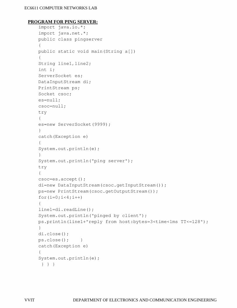
VVIT DEPARTMENT OF ELECTRONICS AND COMMUNICATION ENGINEERING
PROGRAM FOR PING SERVER:import java.io.*;import java.net.*;public class pingserver{public static void main(String a[]){String line1,line2;int i;ServerSocket es;DataInputStream di;PrintStream ps;Socket csoc;es=null;csoc=null;try{es=new ServerSocket(9999);}catch(Exception e){System.out.println(e);}System.out.println("ping server");try{csoc=es.accept();di=new DataInputStream(csoc.getInputStream());ps=new PrintStream(csoc.getOutputStream());for(i=0;i<4;i++){line1=di.readLine();System.out.println("pinged by client");ps.println(line1+"reply from host:bytes=3<time<1ms TT<=128");}di.close();ps.close(); }catch(Exception e){System.out.println(e);} } }
EC6611 COMPUTER NETWORKS LAB
VVIT DEPARTMENT OF ELECTRONICS AND COMMUNICATION ENGINEERING
PROGRAM FOR PING CLIENT:
import java.io.*;import java.net.*;public class pingclient{public static void main(String args[]){PrintWriter out=null;int i,j,k;BufferedReader networkIn=null;try{System.out.println("enter the IP address:");DataInputStream in = new DataInputStream(System.in);String ip = in.readLine();Socket thesocket = new Socket(ip, 9999);networkIn = new BufferedReader(newInputStreamReader(System.in));out = new PrintWriter(thesocket.getOutputStream());System.out.println("\npinging" + ip + "with 32 bytes ofdata\n");for (i = 0; i < 4; i++){out.println(ip);out.flush();String inp = networkIn.readLine();if (inp != null){for (j = 0; j < 10000; j++){for (k = 0; k < 50000; k++){}}System.out.println("reply from" + inp);}else{for (i = 0; i < 4; i++){for (j = 0; j < 10000; j++){for (k = 0; k < 50000; k++){}System.out.println("\nrequest time out");}}}}
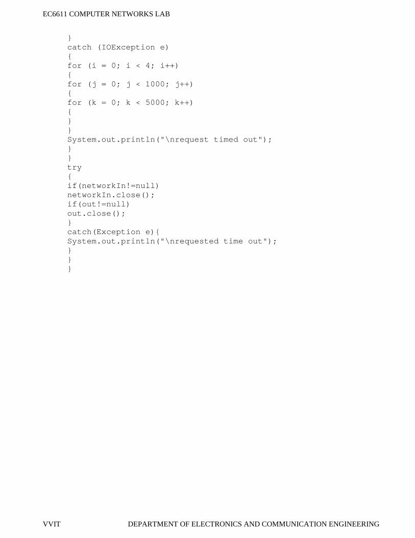
EC6611 COMPUTER NETWORKS LAB
VVIT DEPARTMENT OF ELECTRONICS AND COMMUNICATION ENGINEERING
}catch (IOException e){for (i = 0; i < 4; i++){for (j = 0; j < 1000; j++){for (k = 0; k < 5000; k++){}}System.out.println("\nrequest timed out");}}try{if(networkIn!=null)networkIn.close();if(out!=null)out.close();}catch(Exception e){System.out.println("\nrequested time out");}}}
EC6611 COMPUTER NETWORKS LAB
VVIT DEPARTMENT OF ELECTRONICS AND COMMUNICATION ENGINEERING
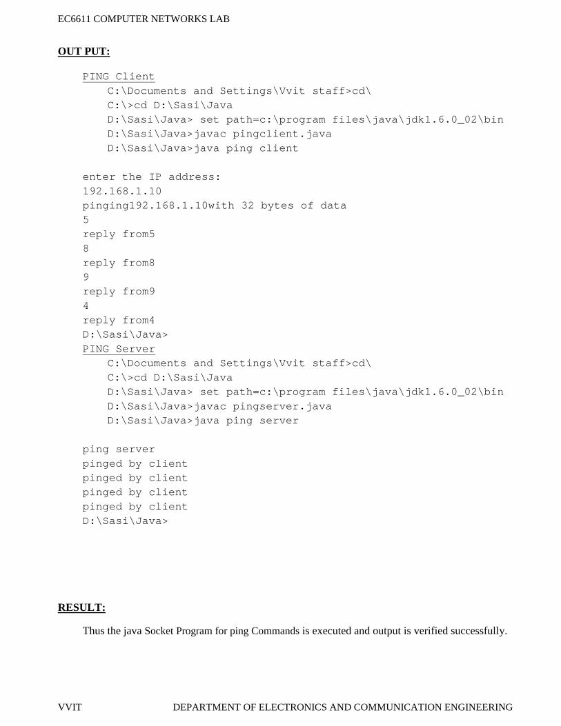
OUT PUT:
PING ClientC:\Documents and Settings\Vvit staff>cd\C:\>cd D:\Sasi\JavaD:\Sasi\Java> set path=c:\program files\java\jdk1.6.0_02\binD:\Sasi\Java>javac pingclient.javaD:\Sasi\Java>java ping client
enter the IP address:192.168.1.10pinging192.168.1.10with 32 bytes of data5reply from58reply from89reply from94reply from4D:\Sasi\Java>PING Server
C:\Documents and Settings\Vvit staff>cd\C:\>cd D:\Sasi\JavaD:\Sasi\Java> set path=c:\program files\java\jdk1.6.0_02\binD:\Sasi\Java>javac pingserver.javaD:\Sasi\Java>java ping server
ping serverpinged by clientpinged by clientpinged by clientpinged by clientD:\Sasi\Java>
RESULT:
Thus the java Socket Program for ping Commands is executed and output is verified successfully.
EC6611 COMPUTER NETWORKS LAB
VVIT DEPARTMENT OF ELECTRONICS AND COMMUNICATION ENGINEERING
EX.NO:8
DATE:
WRITE A SOCKET PROGRAM FOR TALK COMMANDS.
AIM:
To write a program for talk commands using socket programming to send and receive messagefrom client and server using connection oriented service.
APPARATUS REQUIERD:
JDK TOOLKIT 5.0
Standalone desktop
PROCEDURE:Server:
1. Start the program.2. Create server and client sockets.3. Use input streams to get the message from user.4. Use output stream to send message to the client.5. Wait for client to display this message and write a new one to be displayed by the server.6. Display message given at client using input streams read from socket.7. If in the message given by server or client, the word “end” is encountered, exit both the
programs.8. Stop the program.
Client:1. Start the program.2. Create a client socket that connects to the required host and port.3. Using input streams read message given by server and print it.4. Using input streams, get message from user to be given to the server.5. Use output streams to write message to the server.6. Stop the program
EC6611 COMPUTER NETWORKS LAB
VVIT DEPARTMENT OF ELECTRONICS AND COMMUNICATION ENGINEERING
PROGRAM FOR TALK SERVER:import java.io.*;import java.net.*;Public class talk server{Public static void main (String args []) throws Exception{Server Socket ecsvr=null;String line1, line 2;Data Input Stream dis =null;Print Stream pts=null;Socket cls ckt=null;Buffered Reader in1=null;Server =new Server Socket(9999);System. out. Println ("TALK SERVER");System. Out. println ("----------------------");clsckt= ecsvr. accept ();dis =new Data Input Stream (cls ckt. Get Input Stream ());pts =new Print Stream(cls ckt. get Output Stream());System. Out. Println ("Node successfully connected..");While (true){line1=dis. readLine ();System. Out .println("Message Received");System. out. println("The Message ="+line1);in1=new Buffered Reader (new Input Stream Reader (System. in));line2=in1.readLine ();if(line2.equals("end")){break;}pts. println (line2);pts. Flush ();System .out. println ("Message sent successfully");}dis. close();pts. close();}}
EC6611 COMPUTER NETWORKS LAB
VVIT DEPARTMENT OF ELECTRONICS AND COMMUNICATION ENGINEERING
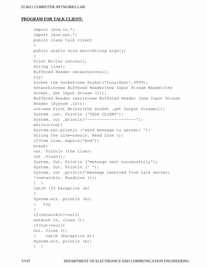
PROGRAM FOR TALK CLIENT:
import java.io.*;import java.net.*;public class talk client{public static void main(String args[]){Print Writer out=null;String line1;Buffered Reader networkln=null;try{Socket the Socket=new Socket("LocalHost",9999);networkln=new Buffered Reader(new Input Stream Reader(theSocket. Get Input Stream ()));Buffered Reader userln=new Buffered Reader (new Input StreamReader (System .in));out=new Print Writer(the Socket .get Output Stream());System .out. Println ("TALK CLIENT");System. out .println("--------------------");while(true){System.out.println ("send message to server: ");String the Line=userln. Read Line ();if(the Line. equals("end"))break;out. Println (the Line);out .flash();System. Out. Println ("message sent successfully");System. Out. Println (" ");System. out .println("message received from talk server:"+networkln. ReadLine ());} }Catch (IO Exception (e){System.err. println (e);} try{if(networkln!=null)network ln. close ();if(out!=null)Out. Close ();} catch (Exception e){System.err. println (e);} }
EC6611 COMPUTER NETWORKS LAB
VVIT DEPARTMENT OF ELECTRONICS AND COMMUNICATION ENGINEERING
OUTPUT:TALK server
C:\Documents and Settings\Vvit staff>cd\C:\>cd D:\Sasi\JavaD:\Sasi\Java> set path=c:\program files\java\jdk1.6.0_02\binD:\Sasi\Java>javac talkerver.javaD:\Sasi\Java>java talk server
TALK SERVER----------------------Node successfully connected.Message ReceivedThe Message =HAIHI..Message sent successfullyMessage ReceivedThe Message =HOW ARE YOUI AM FINEMessage sent successfullyMessage ReceivedThe Message =K BYEendD:\Sasi\Java>
TALK Client
C:\Documents and Settings\Vvit staff>cd\C:\>cd D:\Sasi\JavaD:\Sasi\Java> set path=c:\program files\java\jdk1.6.0_02\binD:\Sasi\Java>javac talkclient.javaD:\Sasi\Java>java talk client
TALK CLIENT--------------------send message to server: HAImessage sent successfullymessage received from talk server: HI..send message to server: HOW ARE YOUmessage sent success fullmessage received from talk server: I AM FINEsend message to server: K BYEmessage sent successfullysend message to server:endD:\Sasi\Java>
EC6611 COMPUTER NETWORKS LAB
VVIT DEPARTMENT OF ELECTRONICS AND COMMUNICATION ENGINEERING
RESULT:
Thus the java Socket Program for Talk Commands is executed and output is verified
successfully.
EC6611 COMPUTER NETWORKS LAB
VVIT DEPARTMENT OF ELECTRONICS AND COMMUNICATION ENGINEERING
EX.NO:9
DATE:
IMPLEMENTATION OF DISTANCE VECTOR ROUTING ALGORITHM
AIM:To simulate the distance vector routing protocol to maintain routing tables as the traffic and
topology of the network changes using LAN-T software.
APPARATUS REQUIERD:
• LTS-01 trainer kit and LAN-T Software.
• 2 Computers with Windows XP and Ethernet port available on them.
• RJ-45 to RJ-45 LAN connecting cables
PROCEDURE:
1. Double click on LAN-T Routing Simulator icon from the desktop.
2. Click load button and browse open C:\Lantrain\Config\ linear.txt.
EC6611 COMPUTER NETWORKS LAB
VVIT DEPARTMENT OF ELECTRONICS AND COMMUNICATION ENGINEERING
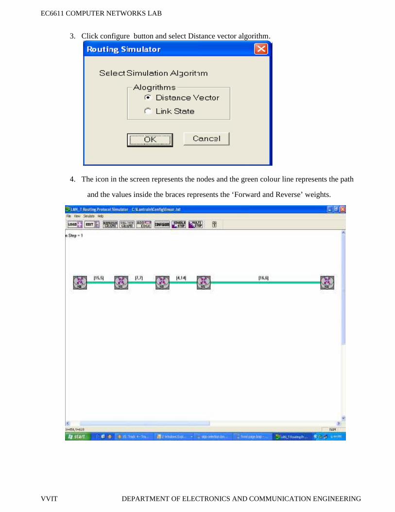
3. Click configure button and select Distance vector algorithm.
4. The icon in the screen represents the nodes and the green colour line represents the path
and the values inside the braces represents the ‘Forward and Reverse’ weights.
EC6611 COMPUTER NETWORKS LAB
VVIT DEPARTMENT OF ELECTRONICS AND COMMUNICATION ENGINEERING
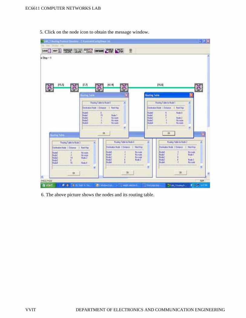
5. Click on the node icon to obtain the message window.
6. The above picture shows the nodes and its routing table.
EC6611 COMPUTER NETWORKS LAB
VVIT DEPARTMENT OF ELECTRONICS AND COMMUNICATION ENGINEERING
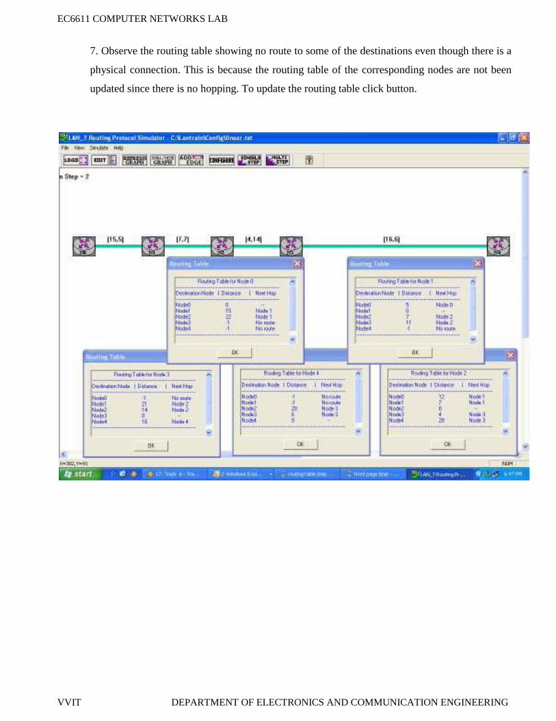
7. Observe the routing table showing no route to some of the destinations even though there is a
physical connection. This is because the routing table of the corresponding nodes are not been
updated since there is no hopping. To update the routing table click button.
EC6611 COMPUTER NETWORKS LAB
VVIT DEPARTMENT OF ELECTRONICS AND COMMUNICATION ENGINEERING
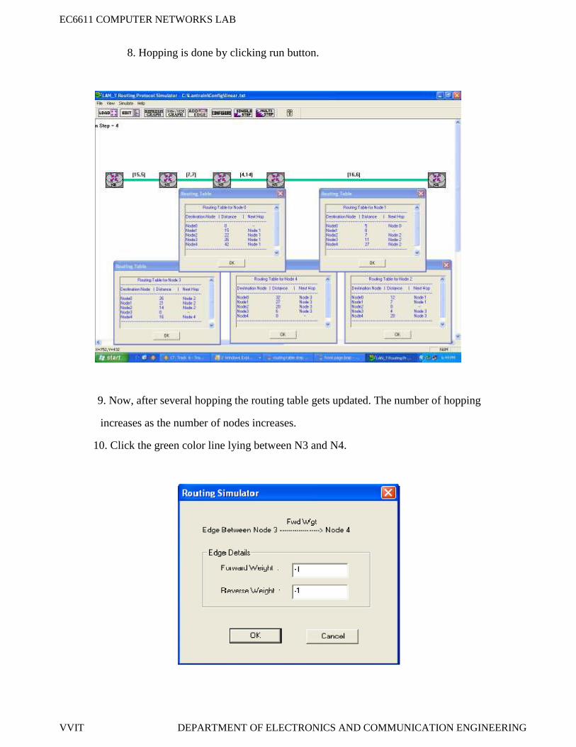
8. Hopping is done by clicking run button.
9. Now, after several hopping the routing table gets updated. The number of hopping
increases as the number of nodes increases.
10. Click the green color line lying between N3 and N4.
EC6611 COMPUTER NETWORKS LAB
VVIT DEPARTMENT OF ELECTRONICS AND COMMUNICATION ENGINEERING
11. Enter the forward and reverse weight as ‘-1’ in order to disconnect N4 from the other nodes.
EC6611 COMPUTER NETWORKS LAB
VVIT DEPARTMENT OF ELECTRONICS AND COMMUNICATION ENGINEERING
12. Now observe the routing table.
.
EC6611 COMPUTER NETWORKS LAB
VVIT DEPARTMENT OF ELECTRONICS AND COMMUNICATION ENGINEERING
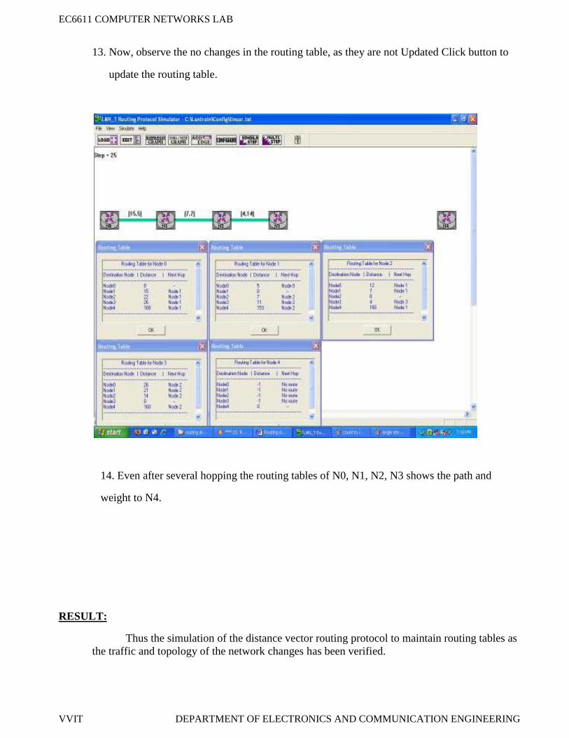
13. Now, observe the no changes in the routing table, as they are not Updated Click button to
update the routing table.
14. Even after several hopping the routing tables of N0, N1, N2, N3 shows the path and
weight to N4.
RESULT:
Thus the simulation of the distance vector routing protocol to maintain routing tables asthe traffic and topology of the network changes has been verified.
EC6611 COMPUTER NETWORKS LAB
VVIT DEPARTMENT OF ELECTRONICS AND COMMUNICATION ENGINEERING
EX.NO:10
DATE:
IMPLEMENTATION OF LINK STATE ROUTING ALGORITHM
AIM:
To simulate the link state routing protocol to maintain routing tables as the traffic and topology
of the network change by using LAN-T Software.
APPARATUS REQUIERD:
• LTS-01 trainer kit and LAN-T Software.
• 2 Computers with Windows XP and Ethernet port available on them.
• RJ-45 to RJ-45 LAN connecting cables.
PROCEDURE:
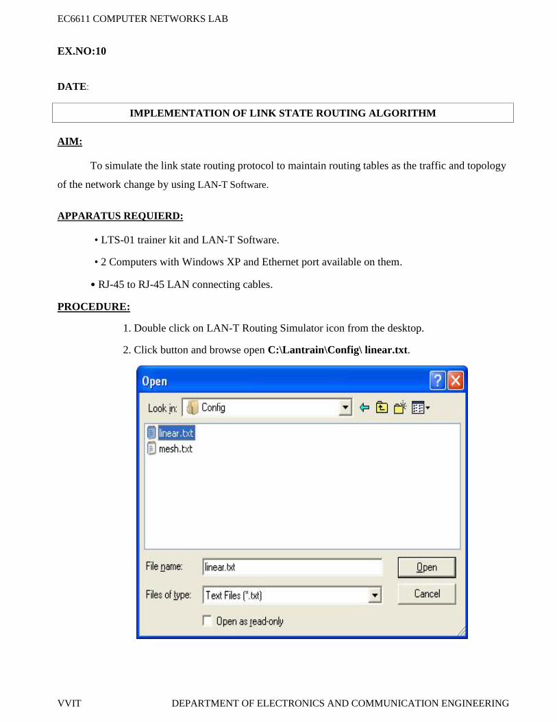
1. Double click on LAN-T Routing Simulator icon from the desktop.
2. Click button and browse open C:\Lantrain\Config\ linear.txt.
EC6611 COMPUTER NETWORKS LAB
VVIT DEPARTMENT OF ELECTRONICS AND COMMUNICATION ENGINEERING
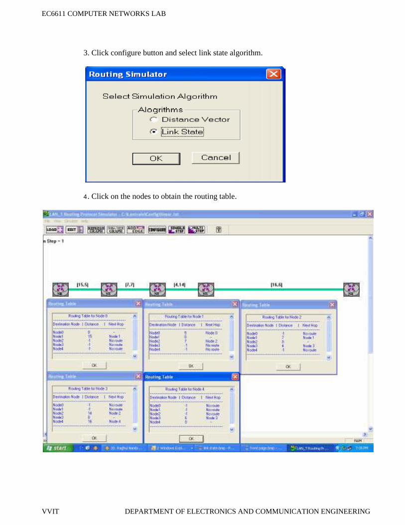
3. Click configure button and select link state algorithm.
4. Click on the nodes to obtain the routing table.
EC6611 COMPUTER NETWORKS LAB
VVIT DEPARTMENT OF ELECTRONICS AND COMMUNICATION ENGINEERING
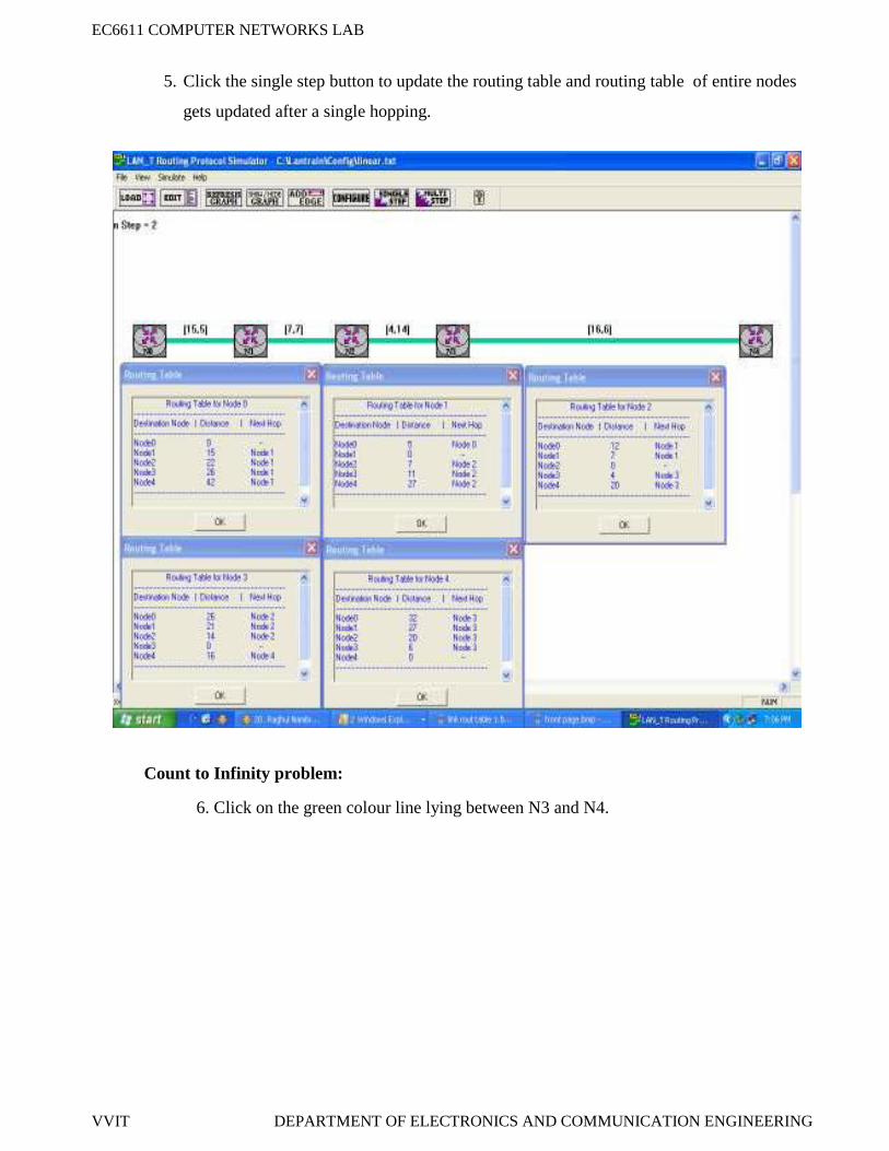
5. Click the single step button to update the routing table and routing table of entire nodes
gets updated after a single hopping.
Count to Infinity problem:
6. Click on the green colour line lying between N3 and N4.
EC6611 COMPUTER NETWORKS LAB
VVIT DEPARTMENT OF ELECTRONICS AND COMMUNICATION ENGINEERING
7. Enter forward and reverse weights as -1 to disconnect N4 from the other nodes.
8. Observe the routing table. The values are not changed as it’s not updated.
9. Click the single step button.
10. Now you could see the routing table for each nodes been updated.
EC6611 COMPUTER NETWORKS LAB
VVIT DEPARTMENT OF ELECTRONICS AND COMMUNICATION ENGINEERING
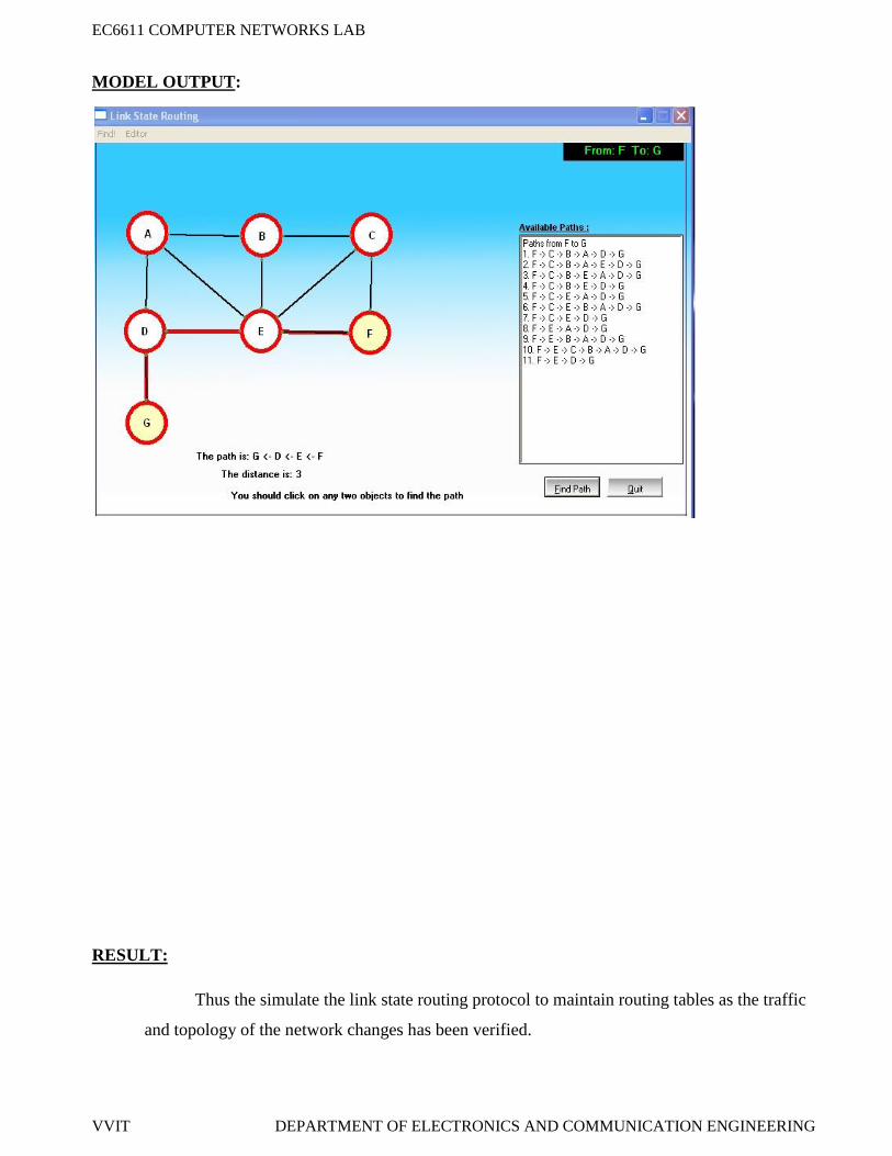
MODEL OUTPUT:
RESULT:
Thus the simulate the link state routing protocol to maintain routing tables as the traffic
and topology of the network changes has been verified.
EC6611 COMPUTER NETWORKS LAB
VVIT DEPARTMENT OF ELECTRONICS AND COMMUNICATION ENGINEERING
EX.NO:11
DATE:
IMPLEMENTATION AND STUDY THE PERFORMANCE OF NETWORK WITHCSMA / CA PROTOCOL
AIM:
To Implement the CSMA/CA protocol for packet communication between a number of nodes
connected to a common bus using LAN-T Software.
APPARATUS REQUIERD:
• LTS-01 trainer kit and LAN-T Software.
• 2 Computers with Windows XP and Ethernet port available on them.
• RJ-45 to RJ-45 LAN connecting cables.
PROCEDURE:
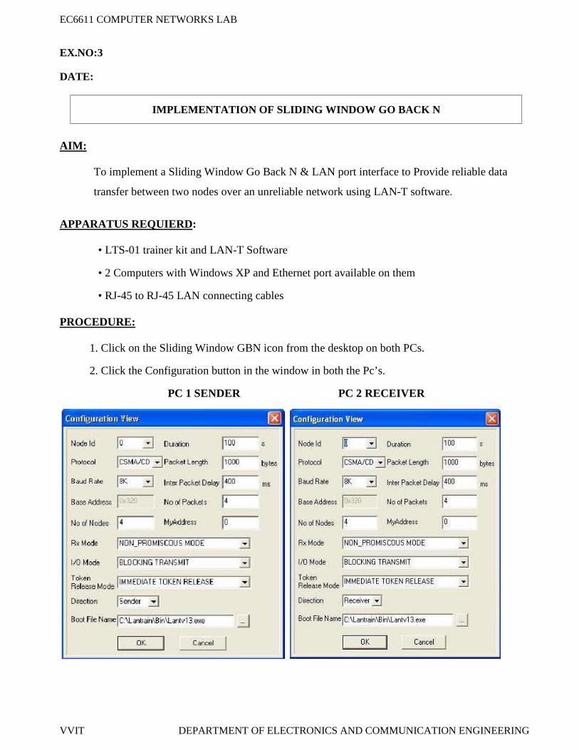
1. Click on the MAC Experiment icon twice from the desktop on both PC’s.
2. Click the Configuration button in the window in both the PC’s.
PC SERVER 1
EC6611 COMPUTER NETWORKS LAB
VVIT DEPARTMENT OF ELECTRONICS AND COMMUNICATION ENGINEERING
PC SERVER2
SETTING THE CONFIGURATION MENU:
3. Click OK button and Download the driver to the NIU using the BOOT button command.
Booting from any one of the applications is enough.
4. Run the experiment by clicking button or by choosing RUN Start from each application.
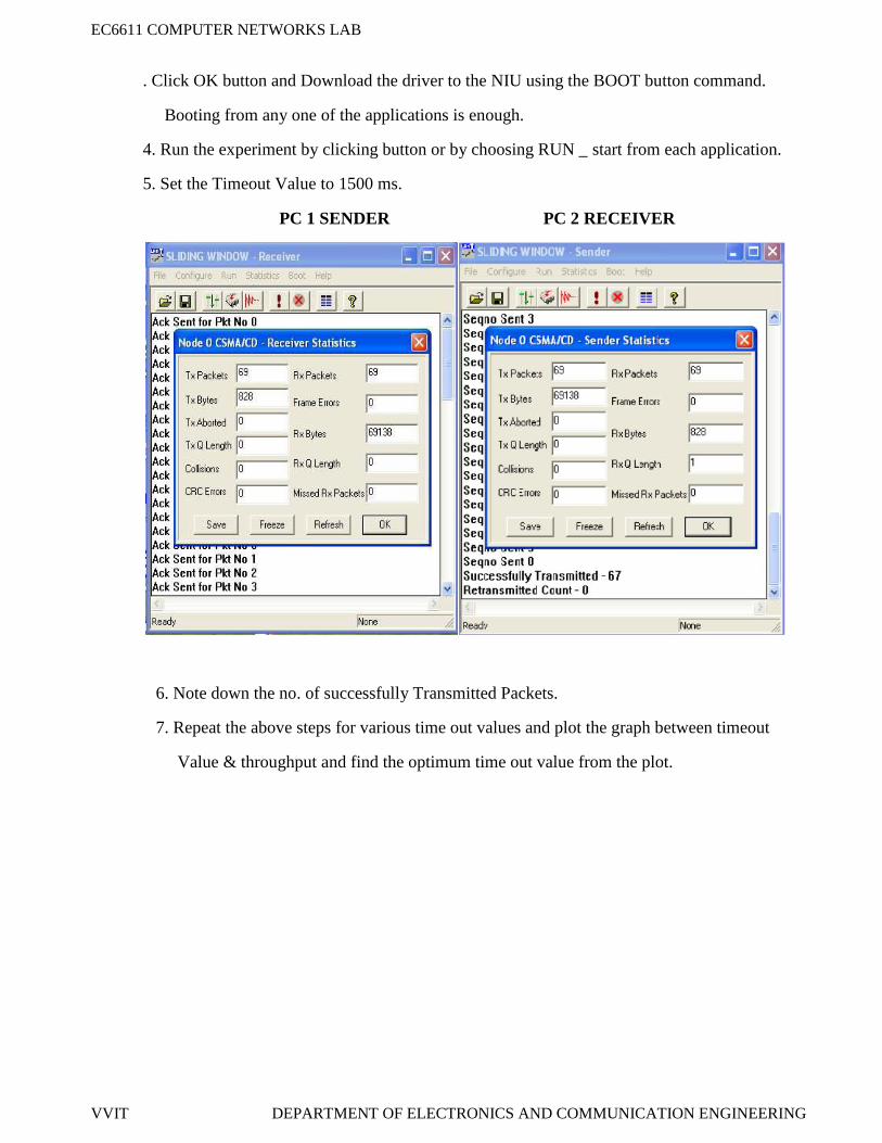
5. View the statistics window for results. To view the statistics window click on button. Only
Tx packets and collision count are taken into account for MAC calculation
PC 1 PC 2
Node ID 0 on config menu 1 and1 on config menu 2
Node ID 0 on config menu 1 and1 on config menu 2
Protocol ALOHA Protocol CSMA/CDBaud Rate 8Kbps (At both the config
menu and NEU)Baud Rate 8Kbps (At both the config
menu and NEU)
Duration 100s Duration 100s
Packet Length 100 bytes Packet Length 100 bytes
Bit Delay 0(at NEU) Bit Delay 0(at NEU)
Direction Sender Direction Receiver
My address 1 My address 2 on config menu 1 and 3 onconfig menu 2
EC6611 COMPUTER NETWORKS LAB
VVIT DEPARTMENT OF ELECTRONICS AND COMMUNICATION ENGINEERING
PC SERVER 1
PC SERVER 2
6. Note down the readings once the experiment is completed.
7. Repeat the above steps for various values of ta.
8. Calculate the Practical offered load from the below given formula and plot the graph
between the practical Offered load and Throughput.
9. Repeat the experiments for various values of Packet length, Node, Data rate and Bit delay.
EC6611 COMPUTER NETWORKS LAB
VVIT DEPARTMENT OF ELECTRONICS AND COMMUNICATION ENGINEERING
Calculation of generated load :
Equation:
N * PG = --------------
C * ta
G is the generated load in the network.N is the number of transmitting nodes. For example, 4 nodes (using 2 computers)P is the packet length expressed in bits; say 100 bytes (800 bits).C is the data rate normally set as 8kbs, which is selected in the NEU.ta is the inter packet delay expressed in seconds; the time interval between two consecutive
packets generated.
Calculation of Throughput (X) from the obtained readings:
Successfully transmitted packet by a node = Tx Packets - Collision Count
(Sum of Successfully Tx packet in all the nodes * Packet Length * 8)X = ---------------------------------------------------------------------------------------
a = (end to end bit delay in bits) / (Packet length in bits) = (bit delay*N) / (P)
Calculation of Offered load:
(Sum of Tx packets in all the nodes * Packet Length * 8)G = --------------------------------------------------------------------------
(Duration of Experiment * Data rate)
EC6611 COMPUTER NETWORKS LAB
VVIT DEPARTMENT OF ELECTRONICS AND COMMUNICATION ENGINEERING
MODEL GRAPH:
MODEL TABULATION:
For bit delay = 1
IPD Tx1 Tx 2 Tx 3 Tx 4G – PracticalOffered Load
X –ThroughputTheoreticalThroughput
RES ULT :
Thus the Implementation of the CSMA/CA protocol for packet communication between
a numbers of nodes connected to a common bus data has been verified.
EC6611 COMPUTER NETWORKS LAB
VVIT DEPARTMENT OF ELECTRONICS AND COMMUNICATION ENGINEERING
EX.NO:12
DATE:
IMPLEMENTATION AND STUDY THE PERFORMANCE OF NETWORK WITHCSMA/CD PROTOCOLS
AIM:
To Implement the CSMA/CD protocol for packet communication between a number of nodes
Connected to a common bus using LANT-T software.
APPARATUS REQUIERD:
• LTS-01 trainer kit and LAN-T Software.
• 2 Computers with Windows XP and Ethernet port available on them.
• RJ-45 to RJ-45 LAN connecting cables.
PROCEDURE:
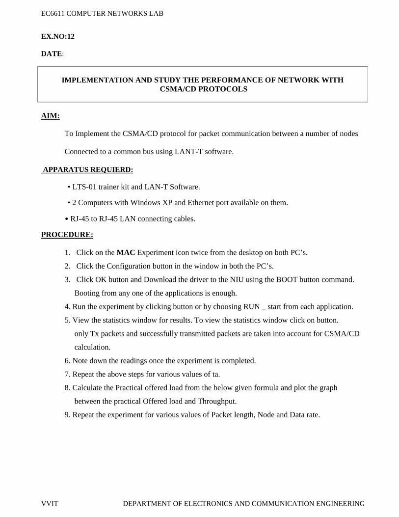
1. Click on the MAC Experiment icon twice from the desktop on both PC’s.
2. Click the Configuration button in the window in both the PC’s.
3. Click OK button and Download the driver to the NIU using the BOOT button command.
Booting from any one of the applications is enough.
4. Run the experiment by clicking button or by choosing RUN _ start from each application.
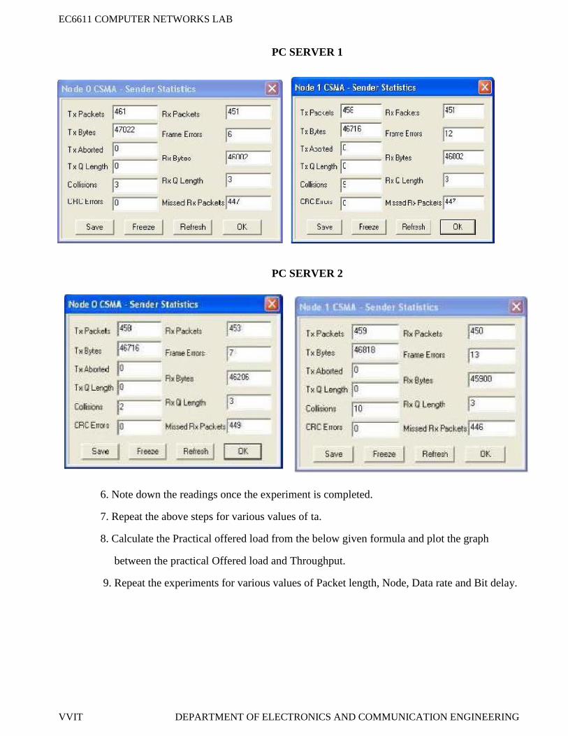
5. View the statistics window for results. To view the statistics window click on button.
only Tx packets and successfully transmitted packets are taken into account for CSMA/CD
calculation.
6. Note down the readings once the experiment is completed.
7. Repeat the above steps for various values of ta.
8. Calculate the Practical offered load from the below given formula and plot the graph
between the practical Offered load and Throughput.
9. Repeat the experiment for various values of Packet length, Node and Data rate.
EC6611 COMPUTER NETWORKS LAB
VVIT DEPARTMENT OF ELECTRONICS AND COMMUNICATION ENGINEERING
SETTING THE CONFIGURATION MENU:
Calculation of Throughput for CSMA/CD protocol:
Equation:
N * PG= --------------
C * ta
G is the generated load in the network.N is the number of transmitting nodes. For example, 4 nodes (using 2 computers)P is the packet length expressed in bits; say 100 bytes (800 bitsC is the data rate normally set as 8kbs, which is selected in the NEU.ta is the inter packet delay expressed in seconds; the time interval between two consecutivePackets generated
Calculation of Throughput (X) from the obtained readings:
Successfully transmitted packet by a node = Tx Packets - Collision Count
(Sum of Successfully Tx packet in all the nodes * Packet Length * 8)X = -------------------------------------------------------------------------------------------
(Duration of Experiment * Data rate)
Calculation of Offered load:
(Sum of Offered load count in all the nodes * Packet Length * 8)G = ----------------------------------------------------------------------------------
(Duration of Experiment * Data rate)
PC 1 PC 2Node ID 0 on config menu 1 and
1 on config menu 2Node ID 0 on config menu 1 and
1 on config menu 2Protocol CSMA/CD Protocol CSMA/CDBaud Rate 8Kbps (At both the config
menu and NEU)Baud Rate 8Kbps (At both the config
menu and NEU)Duration 100s Duration 100sPacket Length 100 bytes Packet Length 100 bytesBit Delay 0(at NEU) Bit Delay 0(at NEU)Direction Sender Direction ReceiverNo of packets 4 No of packets 4
EC6611 COMPUTER NETWORKS LAB
VVIT DEPARTMENT OF ELECTRONICS AND COMMUNICATION ENGINEERING
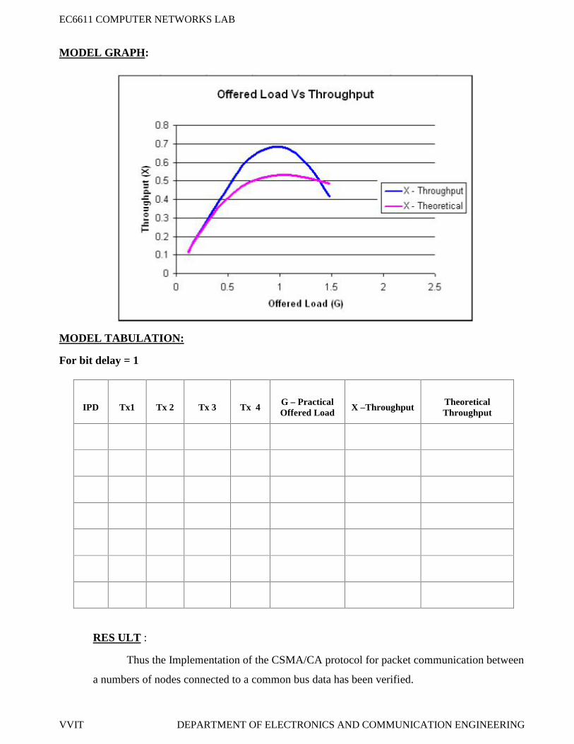
MODEL GRAPH :
MODEL TABULATION:
IPD Tx1 Tx 2 Tx 3 Tx 4 G – PracticalOffered Load
X -Throughput TheoreticalThroughput
RESULT:
Thus the Implementation of the CSMA/CD protocol for packet communication between a
numbers of Nodes connected to a common bus has been verified.
EC6611 COMPUTER NETWORKS LAB
VVIT DEPARTMENT OF ELECTRONICS AND COMMUNICATION ENGINEERING
EX.NO:13
DATE:
IMPLEMENTATION OF DATA ENCRYPTION AND DECRYPTION
AIM:
To implement the Encryption and Decryption of a file using RC4 algorithm.
APPARATUS REQUIERD:
Java JDK 5.0.
Personal computer.
PROCEDURE:
Initial Setup:
1. Install Java JDK 5.0.
2. Browse C:\Lantrain\DataSecurity.
3. Copy the RC4 folder and three class files (Connect, RC4Client, and Server)
and paste it into the Java\jdk1.5\bin folder in both the server and client PC’s.
Setting up the Server:
1. Open the command prompt window (Start _Run _ type cmd).
2. Browse the java bin folder.
3. Type java Server to run the server.
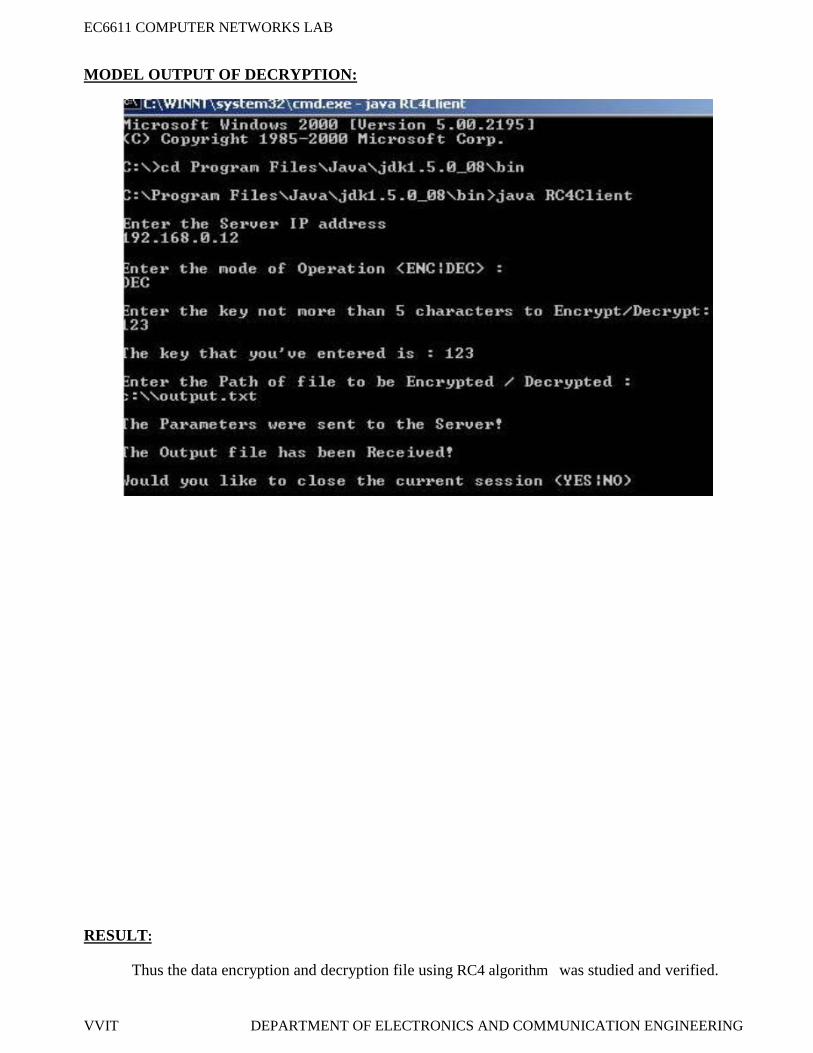
Encrypting a file:
1. Open command prompt in the client side.
2. Browse the java bin folder.
3. Type java RC4Client.
4. Enter the IP address of the server.
5. Enter the mode of operation.
6. Enter the Encryption key not more than 5 characters.
7. Enter the path name of the file to be encrypted. (For e.g.: c:\\abc.txt)
8. Type YES if you like to close the session or type NO if you like to continue decrypting the
Cipher text.
EC6611 COMPUTER NETWORKS LAB
VVIT DEPARTMENT OF ELECTRONICS AND COMMUNICATION ENGINEERING
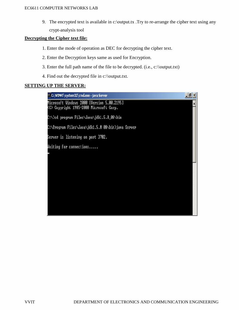
9. The encrypted text is available in c:\output.tx .Try to re-arrange the cipher text using any
crypt-analysis tool
Decrypting the Cipher text file:
1. Enter the mode of operation as DEC for decrypting the cipher text.
2. Enter the Decryption keys same as used for Encryption.
3. Enter the full path name of the file to be decrypted. (i.e., c:\\output.txt)
4. Find out the decrypted file in c:\\output.txt.
SETTING UP THE SERVER:
EC6611 COMPUTER NETWORKS LAB
VVIT DEPARTMENT OF ELECTRONICS AND COMMUNICATION ENGINEERING
MODEL OUT PUTS OF ENCRYPTION:
EC6611 COMPUTER NETWORKS LAB
VVIT DEPARTMENT OF ELECTRONICS AND COMMUNICATION ENGINEERING
MODEL OUTPUT OF DECRYPTION:
RESULT:
Thus the data encryption and decryption file using RC4 algorithm was studied and verified.
EC6611 COMPUTER NETWORKS LAB
VVIT DEPARTMENT OF ELECTRONICS AND COMMUNICATION ENGINEERING
EX.NO:14
DATE:
STUDY OF NETWORK SIMULATOR (NS).AND SIMULATION OF CONGESTIONCONTROL ALGORITHMS USING NS
AIM:
To Study of Network simulator (NS) and Simulation of Congestion Control Algorithms
using NS Tool.
NET WORK SIMULATOR (NS2)Ns overview
Ns programming: A Quick start Case study I: A simple Wireless network Case study II: Create a new agent in Ns
Ns overview
Ns Status Periodical release (ns-2.26, Feb 2003) Platform support FreeBSD, Linux, Solaris, Windows and Mac
WirelessAd hoc routing, mobile IP, sensor-MACTracing, visualization and various utilitiesNS (Network Simulators)
Most of the commercial simulators are GUI driven, while some network simulators are CLIdriven. The network model / configuration describe the state of the network (nodes, routers, switches,and links) and the events (data transmissions, packet error etc.). An important output of simulations isthe trace files. Trace files log every packet, every event that occurred in the simulation and are used foranalysis. Network simulators can also provide other tools to facilitate visual analysis of trends andpotential trouble spots.
Most network simulators use discrete event simulation, in which a list of pending "events" isstored, and those events are processed in order, with some events triggering future events such as theevent of the arrival of a packet at one node triggering the event of the arrival of that packet at adownstream node.
Simulation of networks is a very complex task. For example, if congestion is high, thenestimation of the average occupancy is challenging because of high variance. To estimate the likelihoodof a buffer overflow in a network, the time required for an accurate answer can be extremely large.Specialized techniques such as "control varieties" and "importance sampling" have been developed tospeed simulation.
EC6611 COMPUTER NETWORKS LAB
VVIT DEPARTMENT OF ELECTRONICS AND COMMUNICATION ENGINEERING
Examples of network simulatorsThere are many both free/open-source and proprietary network simulators. Examples of
notable network simulation software are, ordered after how often they are mentioned in researchpapers:
Network simulators serve a variety of needs. Compared to the cost and time involved in settingup an entire test bed containing multiple networked computers, routers and data links, networksimulators are relatively fast and inexpensive. They allow engineers, researchers to test scenarios thatmight be particularly difficult or expensive to emulate using real hardware - for instance, simulating ascenario with several nodes or experimenting with a new protocol in the network. Network simulatorsare particularly useful in allowing researchers to test new networking protocols or changes to existingprotocols in a controlled and reproducible environment. A typical network simulator encompasses awide range of networking technologies and can help the users to build complex networks from basicbuilding blocks such as a variety of nodes and links. With the help of simulators, one can designhierarchical networks using various types of nodes like computers, hubs, bridges, routers, switches,links, mobile units etc.
Various types of Wide Area Network (WAN) technologies like TCP, ATM, IP etc. and LocalArea Network (LAN) technologies like Ethernet, token rings etc., can all be simulated with a typicalsimulator and the user can test, analyze various standard results apart from devising some novelprotocol or strategy for routing etc. Network simulators are also widely used to simulate battlefieldnetworks in Network-centric warfare
There are a wide variety of network simulators, ranging from the very simple to the verycomplex. Minimally, a network simulator must enable a user to represent a network topology,specifying the nodes on the network, the links between those nodes and the traffic between the nodes.More complicated systems may allow the user to specify everything about the protocols used to handletraffic in a network. Graphical applications allow users to easily visualize the workings of theirsimulated environment. Text-based applications may provide a less intuitive interface, but may permitmore advanced forms of customization.
Packet lossOccurs when one or more packets of data travelling across a computer network fail to reach
their destination. Packet loss is distinguished as one of the three main error types encountered in digitalcommunications; the other two being bit error and spurious packets caused due to noise.
Packets can be lost in a network because they may be dropped when a queue in the networknode overflows. The amount of packet loss during the steady state is another important property of acongestion control scheme. The larger the value of packet loss, the more difficult it is for transport layerprotocols to maintain high bandwidths, the sensitivity to loss of individual packets, as well as tofrequency and patterns of loss among longer packet sequences is strongly dependent on the applicationitself.
EC6611 COMPUTER NETWORKS LAB
VVIT DEPARTMENT OF ELECTRONICS AND COMMUNICATION ENGINEERING
Throughput
This is the main performance measure characteristic, and most widely used. In communicationnetworks, such as Ethernet or packet radio, throughput or network throughput is the average rate ofsuccessful message delivery over a communication channel. The throughput is usually measured in bitsper second (bit/s mbps), and sometimes in data packets per second or data packets per time slot Thismeasure how soon the receiver is able to get a certain amount of data send by the sender. It isdetermined as the ratio of the total data received to the end to end delay. Throughput is an importantfactor which directly impacts the network performance
DelayDelay is the time elapsed while a packet travels from one point e.g., source premise or network
ingress to destination premise or network degrees. The larger the value of delay, the more difficult it isfor transport layer protocols to maintain high band widths. We will calculate end to end delay
Queue LengthA queuing system in networks can be described as packets arriving for service, waiting for service
if it is not immediate, and if having waited for service, leaving the system after being served. Thusqueue length is very important characteristic to determine that how well the active queue managementof the congestion control algorithm has been working.
RESULT:
Thus the study of Network simulator (NS2) has discussed and studied.
EC6611 COMPUTER NETWORKS LAB
VVIT DEPARTMENT OF ELECTRONICS AND COMMUNICATION ENGINEERING
EX. NO: 15
DATE:
NETWORK TOPOLOGY - TOKEN BUS
AIM:To implement the network topology by token passing access in token bus LAN using LAN-T Software.
APPARATUS REQUIERD:
• LTS-01 trainer kit and LAN-T software.
• 2 Computers with Windows XP and Ethernet port available on them.
• RJ-45 to RJ-45 LAN connecting cables.
PROCEDURE:1. Click on the Token Bus icon twice from the desktop.
2. Click the Configuration button in the window in both the PC’s.
PC 1
EC6611 COMPUTER NETWORKS LAB
VVIT DEPARTMENT OF ELECTRONICS AND COMMUNICATION ENGINEERING
SETTING THE CONFIGURATION MENU:
Note: All the nodes have to be configured as ‘Senders’. Set the topology as ‘Bus’.
*CSMA/CA application is built on Aloha shell script and hence we select protocol as Aloha.
3. Click OK button and Download the driver to the NIU using the BOOT button command.
Booting from any one of the applications is enough.
4. Run the experiment by clicking button or by choosing RUN start from each application.
Run the all the experiments at the same time.
5. Enter the THT time in all nodes and press the OK button first in the node, which has
the lowest Priority of my Address.
PC 1 PC 2
Node ID 0 on config menu 1 and1 on config menu 2
Node ID 0 on config menu 1 and1 on config menu 2
Protocol ALOHA Protocol ALOHA
Baud Rate 8Kbps (At both the configmenu and NEU)
Baud Rate 8Kbps (At both the configmenu and NEU)
Duration 100s Duration 100s
Packet Length 100 bytes Packet Length 100 bytes
Bit Delay 0(at NEU) Bit Delay 0(at NEU)
Direction Sender Direction Sender
EC6611 COMPUTER NETWORKS LAB
VVIT DEPARTMENT OF ELECTRONICS AND COMMUNICATION ENGINEERING
PC SERVER 2
6. Set the Token Holding Time (THT) (say 2000 ms).
7. View the statistics window for results. To view the statistics window, click run button.
8. Note down the readings once the experiment is completed.
9. Repeat the above steps for various values of ta.
10. Calculate the Practical offered load from the below given formula and plot the graph
between the Practical Offered load and Throughput.
11. Repeat the experiment for various values of Packet length, Node, Data rate.
12. Repeat the above steps, while running the experiment set the BER to 10-2 or
try to stop one of the nodes and observe the behavior and explain the same.
EC6611 COMPUTER NETWORKS LAB
VVIT DEPARTMENT OF ELECTRONICS AND COMMUNICATION ENGINEERING
Calculation of the generated load:
N * PG = ------
C * ta
G is the generated load in the network.
N is the number of transmitting nodes. For example, 4 nodes (using 2 computers)
P is the packet length expressed in bits; say 100 bytes (800 bits).
C is the data rate normally set as 8kbs, which is selected in the NEU.
ta is the inter packet delay expressed in seconds;.
Calculation of Throughput (X) from the obtained readings:
(Sum of Tx packet in all the nodes * Packet Length * 8)X = -----------------------------------------------------------------------------
(Duration of Experiment * Data rate)
Calculation of the Offered load:
N * PG = ------
C * ta
G – Offered loadN – Number of nodesP – Packet length in bitsC – Data rate in bits/secta – Inter packet delay in millisecs.
EC6611 COMPUTER NETWORKS LAB
VVIT DEPARTMENT OF ELECTRONICS AND COMMUNICATION ENGINEERING
MODEL GRAPH:
MODEL TABULATION:
IPD Tx 1 Tx 2 Tx 3 Tx 4 G – OfferedLoad
X –Throughput
Avg Delay
RESULT:
Thus the implementation of the token passing access in token bus-lan has been calculated and
verified.
EC6611 COMPUTER NETWORKS LAB
VVIT DEPARTMENT OF ELECTRONICS AND COMMUNICATION ENGINEERING
EX. NO: 16
DATE:
NETWORK TOPOLOGY - TOKEN RING
AIM:To implement the token passing access in Token Ring by using LAN-T software.
APPARATUS REQUIERD:
• LTS-01 trainer kit and LAN-T software.
• 2 Computers with Windows XP and Ethernet port available on them
• RJ-45 to RJ-45 LAN connecting cables
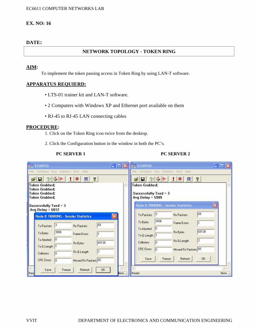
PROCEDURE:1. Click on the Token Ring icon twice from the desktop.
2. Click the Configuration button in the window in both the PC’s.
PC SERVER 1 PC SERVER 2
EC6611 COMPUTER NETWORKS LAB
VVIT DEPARTMENT OF ELECTRONICS AND COMMUNICATION ENGINEERING
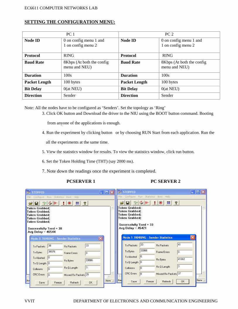
SETTING THE CONFIGURATION MENU:
Note: All the nodes have to be configured as ‘Senders’. Set the topology as ‘Ring’3. Click OK button and Download the driver to the NIU using the BOOT button command. Booting
from anyone of the applications is enough.
4. Run the experiment by clicking button or by choosing RUN Start from each application. Run the
all the experiments at the same time.
5. View the statistics window for results. To view the statistics window, click run button.
6. Set the Token Holding Time (THT) (say 2000 ms).
7. Note down the readings once the experiment is completed.
PCSERVER 1 PC SERVER 2
PC 1 PC 2
Node ID 0 on config menu 1 and1 on config menu 2
Node ID 0 on config menu 1 and1 on config menu 2
Protocol RING Protocol RING
Baud Rate 8Kbps (At both the configmenu and NEU)
Baud Rate 8Kbps (At both the configmenu and NEU)
Duration 100s Duration 100s
Packet Length 100 bytes Packet Length 100 bytes
Bit Delay 0(at NEU) Bit Delay 0(at NEU)
Direction Sender Direction Sender
EC6611 COMPUTER NETWORKS LAB
VVIT DEPARTMENT OF ELECTRONICS AND COMMUNICATION ENGINEERING
8. Repeat the above steps for various values of ta.
9. Calculate the Practical offered load from the below given formula and plot the graph
between the practical Offered load and Throughput.
10. Repeat the experiment for various values of Packet length, Node, Data rate.
11. Repeat the above steps, while running the experiment set the BER to 10-2 or
try to stop one of the nodes and observe the behavior and explain the same.
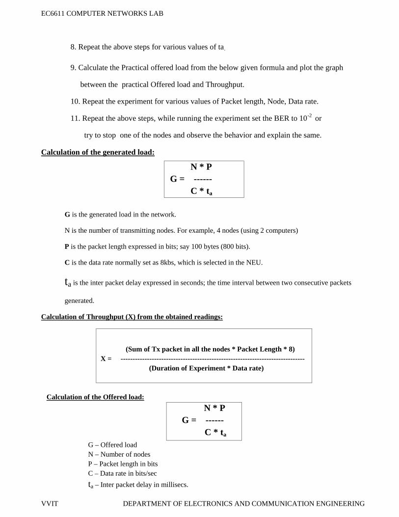
Calculation of the generated load:
N * PG = ------
C * ta
G is the generated load in the network.
N is the number of transmitting nodes. For example, 4 nodes (using 2 computers)
P is the packet length expressed in bits; say 100 bytes (800 bits).
C is the data rate normally set as 8kbs, which is selected in the NEU.
ta is the inter packet delay expressed in seconds; the time interval between two consecutive packets
generated.
Calculation of Throughput (X) from the obtained readings:
(Sum of Tx packet in all the nodes * Packet Length * 8)X = -----------------------------------------------------------------------------
(Duration of Experiment * Data rate)
Calculation of the Offered load:
N * PG = ------
C * ta
G – Offered loadN – Number of nodesP – Packet length in bitsC – Data rate in bits/sec
ta – Inter packet delay in millisecs.
EC6611 COMPUTER NETWORKS LAB
VVIT DEPARTMENT OF ELECTRONICS AND COMMUNICATION ENGINEERING
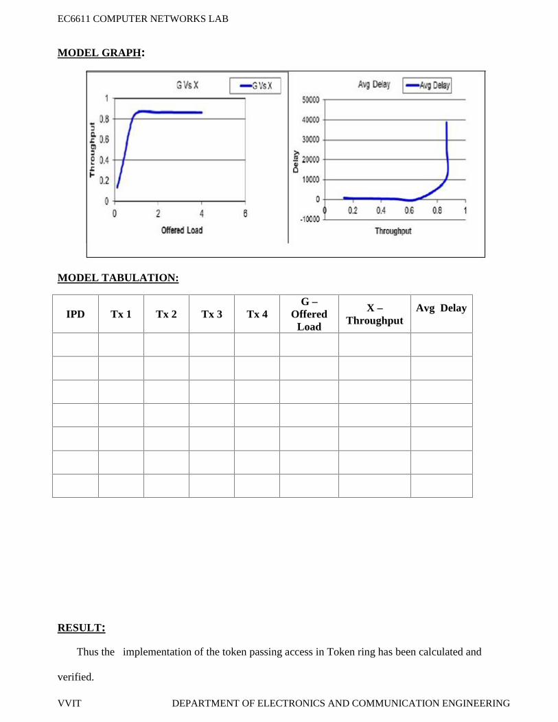
MODEL GRAPH:
MODEL TABULATION:
IPD Tx 1 Tx 2 Tx 3 Tx 4G –
OfferedLoad
X –Throughput
Avg Delay
RESULT:
Thus the implementation of the token passing access in Token ring has been calculated and
verified.
EC6611 COMPUTER NETWORKS LAB
VVIT DEPARTMENT OF ELECTRONICS AND COMMUNICATION ENGINEERING
EX. NO: 17
DATE:
IMPLEMENTATION OF HIGH LEVEL DATA LINK CONTROL
AIM:
To write a c program to implement a data link control for bit stuffing method by using C-editor.
APPARATUS REQUIERD:
C -editor
Standalone desktop.
PROCEDURE:
1. Start the program.
2. Open C-editor.
3. Type the C program.
4. Save the program with file name ext .c.
5. Run the program.
6. If any error occurs in the program correct the error and again run the program.
7. Enter the data of message bit.
8. Check the entered data.
9. Stop the program.
EC6611 COMPUTER NETWORKS LAB
VVIT DEPARTMENT OF ELECTRONICS AND COMMUNICATION ENGINEERING
PROGRAM FOR DATA LINK CONTROL:
#include<stdio.h>
#include<conio.h>void charc(void);void main(){int choice;while(1){printf("\n\n\n1.character stuffing");printf("\n\n2.exit");printf("\n\n\n enter choice");scanf("%d",& choice);printf("%d", choice);if(choice>2)printf("\n\n invalid option....please renter");switch(choice){case 1:charc ();break;case 2:exit(0);}}}void charc(void){char c[50],d[50],t[50];int i,m,j;clrscr();printf("enter the number of characters\n");scanf("%d",&m);printf("\n enter the characters\n");for(i=0;i<m+1;i++)scanf("%c",&c[i]);}printf("\n original data\n");for(i=0;i<m+1;i++)printf("%c",c[i]);
d[0]='d';d[1]='l';
EC6611 COMPUTER NETWORKS LAB
VVIT DEPARTMENT OF ELECTRONICS AND COMMUNICATION ENGINEERING


![CSMA/CCA: A Modified CSMA/CA Protocol Mitigating the ...cheung/Courses/558/Syllabus/Papers/CSMA … · The medium access control (MAC) ... (MACA) protocol [3], ... MACAW [4]. The](https://static.documents.pub/doc/80x56/5b5b7a167f8b9a302a8e0f8a/csmacca-a-modified-csmaca-protocol-mitigating-the-cheungcourses558syllabuspaperscsma.jpg)


