103
ICCP Interface to the PI System Version 1.0 to 1.8.10.0
ICCPInterface to the PI System
Version 1.0 to 1.8.10.0

How to Contact Us
Phone (510) 297-5800 (main number)(510) 297-5828 (technical support)
Fax (510) 357-8136
E-mail [email protected]
World Wide Web
http://www.osisoft.com
Mail OSIsoftP.O. Box 727San Leandro, CA 94577-0427USA
OSI Software GmbH Hauptstrae 30 D-63674 Altenstadt 1Deutschland
OSI Software, LtdP O Box 8256Symonds StreetAuckland 1035 New Zealand
OSI Software, Asia Pte Ltd152 Beach Road#09-06 Gateway EastSingapore, 189721
Unpublished -- rights reserved under the copyright laws of the United States.RESTRICTED RIGHTS LEGEND
Use, duplication, or disclosure by the Government is subject to restrictions as set forth in subparagraph (c)(1)(ii) of the Rights in Technical Data and Computer Software clause at DFARS 252.227-7013
Trademark statement—PI is a registered trademark of OSI Software, Inc. Microsoft Windows, Microsoft Windows for Workgroups, and Microsoft NT are registered trademarks of Microsoft Corporation. Solaris is a registered trademark of Sun Microsystems. HP-UX is a registered trademark of Hewlett Packard Corp.. IBM AIX RS/6000 is a registered trademark of the IBM Corporation. DUX, DEC VAX
and DEC Alpha are registered trademarks of the Digital Equipment Corporation.pi_iccp.doc
1997-2003 OSI Software, Inc. All rights reserved777 Davis Street, Suite 250, San Leandro, CA 94577
Table of Contents
Introduction....................................................................................................................1Reference Manuals......................................................................................................1
Supported Features......................................................................................................1
Diagram of Hardware Connection................................................................................4
Hardware and Software.................................................................................................5Software Requirements for ICCP.................................................................................5
Server Configuration Issues.....................................................................................5
Hardware Requirements for ICCP................................................................................6
Principles of Operation.................................................................................................7Interface Behavior........................................................................................................7
Basic Data Flow............................................................................................................7
Basic Initialization Behavior..........................................................................................8
Performance and ICCP Usage...................................................................................10
Performance and Logging......................................................................................10
Exception Reporting in ICCP......................................................................................10
Throughput Performance...........................................................................................12
Communication Error Recovery.................................................................................12
Installation Checklist...................................................................................................13
OSI Stack Post Installation Procedures.....................................................................15Installing the MMS Protocol Driver.............................................................................15
Verifying the ODBC Datasource.................................................................................15
Starting the Sisco OSI Stack......................................................................................17
Selecting Stack Startup Parameters..........................................................................18
Digital State Configuration for PI2..............................................................................19
Interface Installation....................................................................................................21Naming Conventions and Requirements....................................................................21
Microsoft DLLs............................................................................................................22
Interface Directories...................................................................................................22
ICCP Interface to the PI System iii

The PIHOME Directory Tree...................................................................................22
Interface Installation Directory................................................................................22
Interface Installation Procedure..................................................................................23
Installing the Interface as an NT Service....................................................................23
PI-ICCP Tag Import Utility...........................................................................................25Installing the Import Utility..........................................................................................25
Utility Operation..........................................................................................................25
Connecting to the ICCP Server..............................................................................25
Importing Tag Names.................................................................................................26
PI Tag Creation......................................................................................................26
Cross Referencing PI Tags.....................................................................................27
Editing PI Tag Data....................................................................................................28
Adding Tags...........................................................................................................28
Edit and Select Modes............................................................................................28
Exporting to a Batch File............................................................................................28
Exiting the TIU............................................................................................................29
Running the Tag Import Utility Offline.........................................................................29
PointSource..................................................................................................................31
PI Point Configuration.................................................................................................33ICCP Data Value Object Format................................................................................33
General PI Tag Configuration Information..................................................................33
Input Tag Configuration..............................................................................................40
Dataset Creation.....................................................................................................40
Performance and ICCP Usage...............................................................................41
Output Tags................................................................................................................41
Writing an ICCP Value............................................................................................42
Output Tag Configuration.......................................................................................42
Performance Point Configuration...............................................................................45
I/O Rate Tag Configuration..........................................................................................47Monitoring I/O Rates on the Interface Node...............................................................47
Configuring the PI Point on the PI Server..................................................................47
Configuring on the Interface Node.............................................................................47
Startup Command File.................................................................................................49Command-Line Parameters.......................................................................................49
ICCP Interface to the PI System iv
Sample pi_iccp.bat File..............................................................................................54
PI_ICCP.ini File..........................................................................................................55
Bilateral Table Information......................................................................................56
Server Data Type Definitions..................................................................................57
Switchover Server AR Names................................................................................58
Interface Node Clock...................................................................................................59
Security.........................................................................................................................61
Starting / Stopping the Interface.................................................................................63Starting Interface as a Service...................................................................................63
Stopping Interface Running as a Service...................................................................63
Buffering.......................................................................................................................65Example piclient.ini File..............................................................................................66
Appendix A: Error and Informational Messages.......................................................67Message Logs............................................................................................................67
Status, Warning, and Error Messages........................................................................67
Messages...................................................................................................................67
System Errors and PI Errors.......................................................................................72
Appendix B: ICCP and MMS Overview.......................................................................73ICCP Communication.................................................................................................73
MMS Channels.......................................................................................................73
Functional Blocks.......................................................................................................73
Object Types..............................................................................................................74
ICCP Types............................................................................................................74
Bilateral Tables...........................................................................................................74
MMS-EASE Toolkit.....................................................................................................75
Protocol Stack........................................................................................................75
Appendix C: Runtime Logging....................................................................................77Run Time Logging Configuration................................................................................77
PDU Logging..............................................................................................................78
Appendix D: Server Compliance................................................................................79
Revision History.............................................................................................................81
ICCP Interface to the PI System v

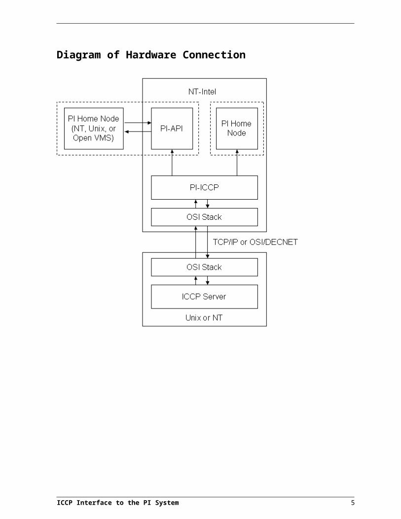
IntroductionThis is a description of the PI-ICCP (Inter-control Center Communications Protocol) Interface to the PI System for Windows NT. The interface is designed to connect to a single ICCP server and using ICCP blocks 1 and 2, retrieve data from or write data to the ICCP server. Note that the PI-ICCP interface is strictly an ICCP client; as such it does not implement the ability for the ICCP server to request or schedule data acquisition from the PI-ICCP interface or the ability to connect to multiple ICCP servers simultaneously. Additional interfaces can be run to facilitate connections to multiple servers. The interface can be run either on a PI3 home node or a client node with network access to a PI2 or PI3 home node. The PI-ICCP interface requires that the SISCO OSI Stack software, which comes bundled with the PI-ICCP interface. The OSI Stack can be installed at the same time as, or prior to, the interface installation.
Reference Manuals
OSIsoft UniInt End User Document
PI Data Archive Manual
PI-API Installation Instructions
ICCP IEC 870-6-503 (iccp503.doc);
IEC 870-6-702 (iccp702.doc);
IEC 870-6-802 (iccp802.doc); and
ICCP User Guide (usrguid5.doc).
These ICCP documents are available on the SISCO web site:
http://www.sisconet.com/techinfo.htm
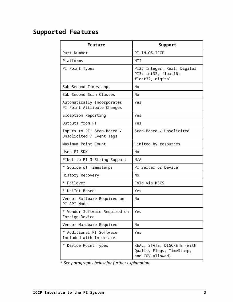
Supported Features
Feature SupportPart Number PI-IN-OS-ICCP
Platforms NTI
PI Point Types PI2: Integer, Real, DigitalPI3: int32, float16, float32, digital
Sub-Second Timestamps No
Sub-Second Scan Classes No
ICCP Interface to the PI System 1
Feature SupportAutomatically Incorporates PI Point Attribute Changes
Yes
Exception Reporting Yes
Outputs from PI Yes
Inputs to PI: Scan-Based / Unsolicited / Event Tags
Scan-Based / Unsolicited
Maximum Point Count Limited by resources
Uses PI-SDK No
PINet to PI 3 String Support N/A
* Source of Timestamps PI Server or Device
History Recovery No
* Failover Cold via MSCS
* UniInt-Based Yes
Vendor Software Required on PI-API Node No
* Vendor Software Required on Foreign Device
Yes
Vendor Hardware Required No
* Additional PI Software Included with Interface
Yes
* Device Point Types REAL, STATE, DISCRETE (with Quality Flags, TimeStamp, and COV allowed)
* See paragraphs below for further explanation.
Source of TimestampsIf the ICCP data value structure includes the timestamp (e.g. the ICCP data types of DATA_REALQTIMESTAMP or DATA_STATEEXTENDED), then the interface will use the timestamp in the data value structure. The use of the /PT switch overrides this behavior and will always use the PI server’s time (as calculated from the offset of the PI server to the PI-API) for the timestamp. If no timestamp is included in the ICCP data value structure (e.g. DATA_REALQ or DATA_STATE), the PI server’s time (as calculated from an offset to the local PI-API node time) is used.
FailoverThe PI-ICCP interface may be set up as a resource in an MSCS Cluster. This would allow cold failover of the application. This is the only type of failover current supported on this interface.
ICCP Interface to the PI System 2
UniInt-BasedUniInt stands for Universal Interface. UniInt is not a separate product or file; it is an OSIsoft-developed template used by our developers, and is integrated into many interfaces, such as the PI-ICCP interface. The purpose of UniInt is to keep a consistent feature set and behavior across as many of our interfaces as possible. It also allows for the very rapid development of new interfaces. In any UniInt-based interface, the interface uses some of the UniInt-supplied configuration parameters and some interface-specific parameters. UniInt is constantly being upgraded with new options and features.
The UniInt End User Document is a supplement to this manual.
Vendor Software RequiredThe PI-ICCP Interface connects as an ICCP client to an ICCP server. The ICCP server must be compliant in ICCP (also referred to as the Telecontrol Application Service Element.2 (TASE.2)) major version 1996, minor version 8.
Additional PI SoftwareThe PI-ICCP interface makes use of the SISCO OSI Stack, which is included in the installation kit of the interface. The OSI Stack is a necessary requirement of the ICCP protocol with is implemented on the Manufacturing Message Specification (MMS) protocol layer.
Device Point TypesThe PI-ICCP interface provides support for analog, digital, and integer values from the ICCP server. The supported ICCP data types are:
Data_Real;
Data_State;
Data_Discrete;
Data_Flags; and
COV_Counter.
These data types are not used individually, but rather in aggregate types (i.e., structures). All data value object structures are supported (for example, those types which include the quality bytes, such as, Data_RealQ or Data_StateQ).
ICCP Interface to the PI System 3

Introduction
Diagram of Hardware Connection
4

Hardware and Software
Software Requirements for ICCPThe PI-ICCP interface requires the Sisco OSI stack to be installed and configured. For detailed installation instructions, see the Sisco OSI stack installation manual and the section OSI Stack Post Installation Procedures later in this manual. The stack driver can be configured to run as a service, or as a standard application. With either configuration, the stack driver will be started by the interface when the interface starts up.
Server Configuration IssuesIn order to improve the performance of the PI-ICCP interface and ICCP server, the maximum MMS PDU size, also referred to as the maximum message size, should be set to 32 kilobytes. If the server does not support this size, then set the value to the maximum allowed. The message size determines the maximum size for ICCP datasets, as approximated by the following formula:
(Max PDU Size – Packet Header Size) / Max ICCP Data Object Name Size
The maximum ICCP name length is 32 bytes. Using the formula above, the maximum dataset size for a 32 KB PDU is slightly over 1000 tags. The actual number of tags in the dataset will be dependent on the actual length of the data object name and the data object’s associated domain name.
Based on the PDU size, the number of available data and transfer sets also needs to be configured for the server. Based on the number of tags within PI and the previous formula, you can determine the approximate number of datasets that will be created by the interface. The ICCP server must be configured to be able to accept at least this many datasets. For exception-based data sets the PI-ICCP interface generates an equal number of transfer sets upon initialization. Thus, an equal number of transfer sets must be configured within the ICCP server in order to allow proper transfer of data. If an inadequate number of datasets is allocated within the server, the interface will not be able to retrieve data from the server at all. If an inadequate number of transfer sets is allocated within the server, datasets unable to obtain a transfer set will be polled instead of receiving reports by exception.
When using polled data access, i.e. datasets are created to retrieve data by polling the server, it is also important to specify the maximum number of outstanding requests in the server. This value should be more than the total number of polled datasets and their siblings (see later in this document). The “maximum outstanding requests” parameter determines how many requests the server can queue before servicing them.
The interface establishes the ICCP association with the ICCP server. This is a hard-coded default parameter.
ICCP Interface to the PI System 5
Hardware Requirements for ICCPNo additional hardware is required beyond the PC and suitable network hardware for access to the ICCP server, such as network card and cable. It is suggested that the ICCP interface be operated on a machine (generally referred to as a PI-API Node) separate from the PI archive. If the interface is on a separate node, it is suggested that Bufserv also be installed on the PI-API Node in the event of problems in communication between the PI Server node and the PI-API Node. See the Bufserv manual for proper installation of that utility
ICCP Interface to the PI System 6
Principles of Operation
Interface BehaviorThe Interface Installation and Administration sections describe how to start and use the interface. This section gives a more technical explanation of the interface’s internal and external performance.
Basic Data FlowThe PI-ICCP Interface acts as an ICCP client to request data from a specified ICCP server. Appendix B: ICCP and MMS Overview contains a brief primer on essential ICCP (and its underlying protocol, MMS) terms and concepts. This section on basic data flow assumes a certain level of familiarity with those concepts.
The interface dynamically groups the data value object names that it is aware of (via its PIPoint configurations). These become DataSets that are named as PI<interface instance ID>_DS<scan class> (e.g. PI1_DS2) and are sized based on the negotiated Maximum PDU size and maximum estimated size of the contained data value objects. The DataSet object essentially contains a list of data value objects. Each dataset object is linked to a TransferSet object, which contains the actual transfer parameters for a given DataSet. The TransferSet object contains the information such as to whether the data is to be transferred via Block1 (polled) or Block2 (Report By Exception or RBE) reporting and the frequency at which that reporting is to occur.
Once the interface has created the datasets and transfersets, the ICCP server assumes control of the scheduling and sending the unsolicited information reports. The presence of a watchdog tag (or constantly polled point) can be configured to ensure that association remains active.
The interface does force the SISCO OSI Stack to monitor the status of the TCP/IP connection to the remote node. If the connection is idle (from the TCP/IP standpoint) for more than 5 minutes, the interface will attempt a reconnection. If the OSI detects no traffic (requests, responses or indications) over a 5-minute period, it will send an ABORT request to both ends of the pipe. The interface then attempts to reconnect to the server if this ABORT request is detected. The 5-minute period can be changed by using the /sito=<time in seconds> switch. Care should be taken not to set this parameter too low, since if it is set smaller than the shortest scan class (or smaller than the integrity timeout if all datasets are exception-based) then the OSI Stack may attempt to abort the connection under normal operation.
This OSI Stack timeout behavior and switch apply only to TCP/IP operation of the OSI Stack. The acknowledgement cycle of the OSI/DECNET protocol is different and more robust with respect to detecting disconnections. If OSI Stack (and therefore, the interface) are using the OSI/DECNET protocol instead, then the monitoring of the OSI Stack connection is still active, however it cannot be configured or altered via the interface.
ICCP Interface to the PI System 7
Basic Initialization BehaviorThe interface will read in all of its parameters from the command line. Then the interface attempts to read the pi_iccp#.ini file for its bilateral table parameters.
It will then attempt to connect to the ICCP server (whose name is in the pi_iccp#.bat file and whose bilateral table parameters are in the pi_iccp#.ini file). As an ICCP client it follows the convention that it will initiate the association by sending an INITIATE request to the remote ICCP server. The PI-ICCP interface is not an ICCP server and does not accept INITIATE requests. The interface refuses/ignores all such requests. It will cycle through the its list of ICCP servers (which is constructed from the server listed in the command arguments and from the [Switchover Servers] section of the pi_iccp#.ini file) until it successfully connects. It will cycle through the entire list once every 2 minutes (120 seconds – in theory, the default TLE for ICCP requests).
Once a successful association has been established, the interface requests its point list from PI and assembles its dataset groupings based on scan class specified for each point. The interface initially groups the points by scan class since all of the transferset parameters for that dataset will be the same. Depending on the number of PI points in a given scan class, there may be more ICCP objects present than can fit in a given dataset (based on the calculated or preconfigured limit of objects per dataset). This is where siblings are used. The excess points spill over into another data set with is named similarly to the first dataset with “_Sibling#” string added on (e.g PI1_DS2_Sibling3). Since the transferset parameters are the same for every dataset in a given scan class, all of the points a given scan class must be configured with similar parameters. In particular, this means that all PI points in a given scan class should be either input or output (similar location2 attributes). Similarly, all PI points in a given scan class must be either polled or RBE. A mixture of point configurations in a scan class will result in a polled input dataset by default. All PI points that refer to the same ICCP object (remember that each part of the data value structure can be stored in a separate PI point) should be placed in the same scan class. Failure to do so can lead to miscorrelation of the data in the multiple tags and forces the ICCP server and client to process multiple separate requests for the same data structure, which in turn degrades performance.
Once the datasets have been collated locally, the interface makes a series of requests to the ICCP server for each dataset. It first attempts to DELETE any object on the ICCP server side with the name of the dataset that is to be created. This is to ensure that there are no outstanding definitions of the dataset, which could potentially lead to confusion. It is most likely that this request will fail (many ICCP server clean up objects after disconnection). However, it is possible in some ICCP server configurations to set a static dataset definition. This feature should be disabled with respect to the association initiated by the PI-ICCP interface. This is because, the order of the list that is received by the interface from the PI server is not guaranteed to be in any particular order. As such, the order of the list that is generated is not known a priori and cannot be guaranteed to be the same between reconnections.
Once the DELETE request is completed and CREATE request for the dataset is successful, the interface will attempt issue a GET Next_DSTransfer_Set Name request. This request asks the ICCP server to allocate the resources for a TransferSet for the interface’s exclusive use and give us a reference to it (the name).
ICCP Interface to the PI System 8

Lastly, the interface makes a request to WRITE to the TransferSet object that it just obtained the name of. This WRITE request establishes the transfer parameters. If the WRITE request succeeds, the ICCP Server should begin to schedule and generate information reports for the datasets and data should be passed from the ICCP server to the PI-ICCP interface.
The interface waits until it has obtained all of the TransferSet names for the datasets in a given scan class before writing to them. This is to compensate for the fact that many ICCP servers place the allocation of new resources (such as the creation of datasets and transfersets) at a lower priority to the scheduling and sending information reports. Note that the user may wish to configure that the slower scan classes first (i.e with lower location4 values), to mitigate the fact that high frequency scan classes can impact the creation of datasets and transfersets of scan classes that are defined after them.
If the DELETE DataSet request fails, this is not necessarily a problem since the object may not exist and thus the request will fail.
However, if the subsequent CREATE request fails, this may be an indication that creation parameters are incorrect (such as the /dom=<ICCP domain> specification), that the permissions for the domain to be accessed are not correct, or that there are not enough resources allocated to the association for the creation of the object. These latter two reasons require alteration of the ICCP server configuration. No alteration of the PI-ICCP interface configuration will change this behavior in those cases.
If the Get Next TransferSet request fails, this can be due to a number of things. Generally, this is due to the security/permission settings on the ICCP server, or the allocation of resources on the ICCP server. Since the dataset creation was successful, the domain specificity of request is generally not a problem. Thus, the allocation of resources is often the problem if the interface can get this far but no further. Some ICCP servers allocate machine resources for DataSets and TransferSets together, while others allocate them separately. Consult the documentation for your ICCP server for more detail.
It should be noted that if the dataset creation is successful, but the Get Next TransferSet request fails, the interface would resort to attempting to schedule the polling (i.e. READ requests) of the specified dataset at the desired frequency. This mode of behavior of the interface is not the recommended operating mode, as it can cause significant load on both the ICCP server and the PI-ICCP interface. In addition, only polling and not exception-based reporting can be supported by this method.
If the WRITE request to the TransferSet object fails, this is most likely a permissions issue with the server. Since the TransferSet object has been created (in theory) when its name was requested and obtained from the ICCP server, a failure to WRITE to the object generally means that security is the issue.
Performance and ICCP UsageICCP uses the concept of datasets to organize points logically. The interface defines one ICCP dataset for every scan class defined when the interface is started. Output tags are not included in datasets.
To maximize performance, all datasets should be exception based.
ICCP Interface to the PI System 9

Principles of Operation
This mode of operation is enabled when all tags are defined as exception based tags (see the description of Location3). Polled datasets retrieve the values for every tag within the dataset at intervals defined on the command line, while exception-based datasets report only values that have changed within the ICCP server.
If a tag appears in more than one dataset, it will be updated at the frequency of the highest frequency dataset, or, if any of the datasets are exception based, the tag will be updated by exception. Though possible, there is no advantage to defining a tag in more than one dataset.
When multiple PI tags are configured for a single ICCP data value object, all tag’s scan class (location4) should be the same. When all tags share the same scan class, the ICCP object will be referenced in a single dataset only. The interface also optimizes the datasets so that an ICCP object will appear only once within a specific dataset. However, if the PI tags do not share the same scan class, the ICCP object will appear in more than one dataset, as the interface does not optimize across datasets.
For exception based data sets, the interface only receives a value from the ICCP server if the value has changed. The startup integrity time out parameter /ito=X is used to explicitly read a value from the server if a new value has not been received within X minutes of the current time. This parameter only applies to exception-based data sets. For scan based data sets, all values go through exception reporting within the interface.
Performance and LoggingThe interface provides extensive logging facilities that can be extremely useful for locating problems with the interface or server configuration and operation. However, the more data that is logged, the slower the interface will operate. Therefore, during normal interface operation, the interface’s logging facilities should be configured with the following options:
low detail level (-Dn, where n < 4 in log.ini file); screen logging off (-Sfalse in log.ini file); forced writes off (-Ffalse in log.ini file); and PDU logging off (the /pdu switch is not placed in the startup batch file)
For more information on Logging see Appendix C.
Exception Reporting in ICCPException reporting in ICCP is different than what is commonly defined with respect to PI applications.
The interface uses the <time> from the /f=<time> switch in the interface startup file to set the “interval timeout” of the transfer sets that are created for the data sets specified for a given scan class. This period differs from the “integrity timeout” which is set explicitly using the /ito=X switch).
The interval timeout is used in both polling and RBE as the time period in which information reports are generated. The basic difference between polling and RBE is the report format; polling is Block1 (a.k.a. a Named Variable List), while RBE is
10

Block2 (a.k.a. a List of Variable Names). Therefore, RBE in Block 2 can still be reported on an interval basis.
However, ICCP offers that additional functionality to set the Change Object flag, which forces immediate reporting of a change (what PI would consider true exception reporting). However, since ICCP makes a distinction, one may want the data reported in Block 2 (RBE), but not be immediately notified of the change (Change Object flag off) on the ICCP server. Note that with respect to the Change Object flag, the ICCP client is at the mercy of the ICCP server to fulfill it the request. The PI-ICCP interface always requests Change Object flag true (i.e. the transferset parameters specify that immediate reporting of exceptions is to be enacted if enabled on the server). Ultimately, the individual ICCP objects in the ICCP server are configured to support it or not.
On additional note, if RBE is active with Change Object set true, one can specify an “Exception Buffer Time”, (configurable in the PI-ICCP interface with the /ebt=# switch) which allows, yet another level of granularity for the reporting behavior. If you enable Change Object, you can specify that the system wait a set period of time before generating the information report for a given dataset (to account for cascade effects).
With the above points in mind, we can more fully describe the method by which the PI-ICCP interface attempts to have exception data reported from the ICCP interface. RBE would force the ICCP server to send a full report (Block1) based on the integrity timeout period. Then, exceptions that occurred would generate information reports immediately (now plus the EBT, if specified in the transferset) for those objects with Change Object set true. If no Change Object true ICCP objects received exceptions during an interval timeout period, then at the end of the interval timeout, an information report would be generated with all of the exceptions for non-Change Object true objects in it. The period at which this interval timeout would be reported is specified by the /f parameter. Remember, the integrity timeout period is set using the /ito=# switch and the Exception Buffer Time parameter is set with the /ebt=# switch.
One additional note, if there are any problems establishing the RBE method of data reporting, the PI-ICCP interface will resort to a polling method for data collection. This is can greatly impact the performance of both the interface and the ICCP server. In addition, if in accordance with OSI’s recommendations for the configuration of exception based points the exception specifications for the points are disabled, the use of polling on those points will result in addition load on the PI server (more events will be written to the snapshot, since exception testing on the data is not being done by either the interface or the ICCP server).
Throughput PerformanceAs of version 1.8.3 of the PI-ICCP interface, the throughput performance of the interface was greatly enhanced by refining the methods by which the interface monitors and processes data being received from the ICCP server. Previous to version 1.8.3 of the interface, the monitoring of the event queue in the OSI Stack was done on a strictly periodic basis. With version 1.8.3 and later, the interface uses the notification event from the OSI Stack to signal an incoming event.
ICCP Interface to the PI System 11
Principles of Operation
When operating the interface to optimize event throughput, one should operate the interface on a dedicated PI-API node with buffering. The PI-Buffer Server should be configured to maximize throughput as well. Special attention should be paid to the MAXTRANSFEROBJS, PAUSERATE, SENDRATE, BUF1SIZE and BUF2SIZE parameters. In particular, the SENDRATE should be set to 1-2 ms, the MAXTRANSFEROBJS parameter should be a multiple of 16 (preferable 1600 or 3200), and the memory buffers (BUF1SIZE and BUF2SIZE) should be set to 128KB (131,072 bytes) or higher to reduce the frequency of buffering to disk. Note that the two memory buffers must be the same size.
Logging for the interface should be minimal (set to level 3 or lower) under normal operating conditions. Since the interface offers the option to have PI tags which can alter the logging parameters at runtime (see Appendix C: Runtime Logging for more information on setting these tags up), this log level should be adequate under most common runtime conditions.
Communication Error RecoveryThe interface uses the SISCO OSI stack for communication to remote ICCP servers. If the connection to the server “goes down” (becomes inoperable), the tags associated with that server will return an error code to PI (I/O Timeout), and will not report any future values to PI until the link to the server becomes operable again. Once the link is operable, the interface automatically starts sending data to PI.
Since the interface relies on the SISCO OSI stack for communication, the ability of the interface to recover from communication errors is completely dependent on the SISCO OSI stack. If the OSI stack is unable to recover from a communication error, such as if a dial-up link is disconnected, the interface will not be able to reconnect to the server until both the stack and the interface are restarted.
12
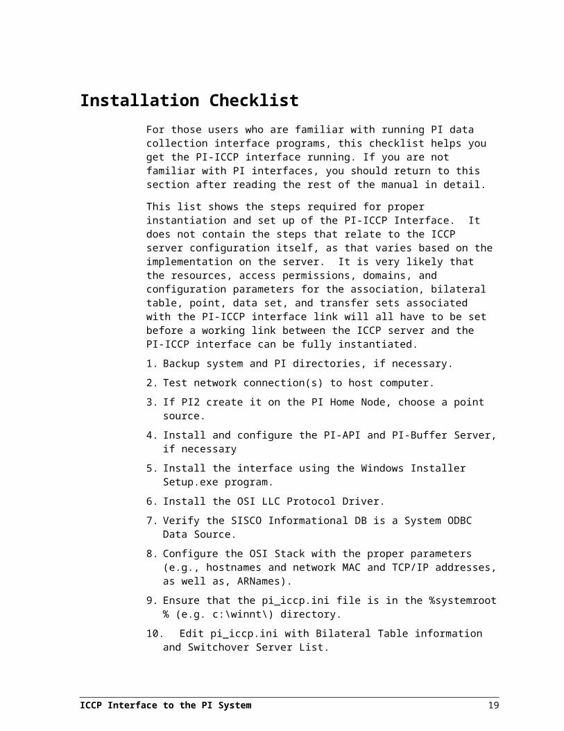
Installation ChecklistFor those users who are familiar with running PI data collection interface programs, this checklist helps you get the PI-ICCP interface running. If you are not familiar with PI interfaces, you should return to this section after reading the rest of the manual in detail.
This list shows the steps required for proper instantiation and set up of the PI-ICCP Interface. It does not contain the steps that relate to the ICCP server configuration itself, as that varies based on the implementation on the server. It is very likely that the resources, access permissions, domains, and configuration parameters for the association, bilateral table, point, data set, and transfer sets associated with the PI-ICCP interface link will all have to be set before a working link between the ICCP server and the PI-ICCP interface can be fully instantiated.
1. Backup system and PI directories, if necessary.
2. Test network connection(s) to host computer.
3. If PI2 create it on the PI Home Node, choose a point source.
4. Install and configure the PI-API and PI-Buffer Server, if necessary
5. Install the interface using the Windows Installer Setup.exe program.
6. Install the OSI LLC Protocol Driver.
7. Verify the SISCO Informational DB is a System ODBC Data Source.
8. Configure the OSI Stack with the proper parameters (e.g., hostnames and network MAC and TCP/IP addresses, as well as, ARNames).
9. Ensure that the pi_iccp.ini file is in the %systemroot% (e.g. c:\winnt\) directory.
10. Edit pi_iccp.ini with Bilateral Table information and Switchover Server List.
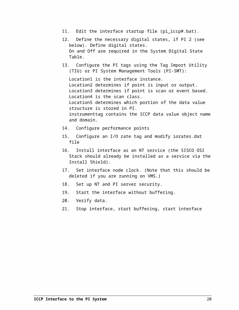
11. Edit the interface startup file (pi_iccp#.bat).
12. Define the necessary digital states, if PI 2 (see below). Define digital states. On and Off are required in the System Digital State Table.
13. Configure the PI tags using the Tag Import Utility (TIU) or PI System Management Tools (PI-SMT):
Location1 is the interface instance.Location2 determines if point is input or output.Location3 determines if point is scan or event based.Location4 is the scan class.Location5 determines which portion of the data value structure is stored in PI.instrumenttag contains the ICCP data value object name and domain.
14. Configure performance points
15. Configure an I/O rate tag and modify iorates.dat file
16. Install interface as an NT service (the SISCO OSI Stack should already be installed as a service via the Install Shield).
ICCP Interface to the PI System 13
17. Set interface node clock. (Note that this should be deleted if you are running on VMS.)
18. Set up NT and PI server security.
19. Start the interface without buffering.
20. Verify data.
21. Stop interface, start buffering, start interface
ICCP Interface to the PI System 14
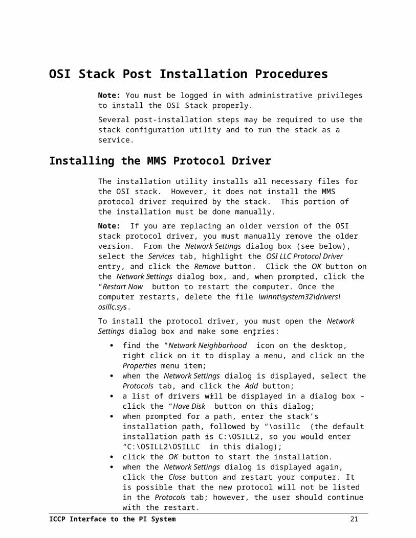
OSI Stack Post Installation ProceduresNote: You must be logged in with administrative privileges to install the OSI Stack properly.
Several post-installation steps may be required to use the stack configuration utility and to run the stack as a service.
Installing the MMS Protocol DriverThe installation utility installs all necessary files for the OSI stack. However, it does not install the MMS protocol driver required by the stack. This portion of the installation must be done manually.
Note: If you are replacing an older version of the OSI stack protocol driver, you must manually remove the older version. From the Network Settings dialog box (see below), select the Services tab, highlight the OSI LLC Protocol Driver entry, and click the Remove button. Click the OK button on the Network Settings dialog box, and, when prompted, click the “Restart Now” button to restart the computer. Once the computer restarts, delete the file \winnt\system32\drivers\osillc.sys.
To install the protocol driver, you must open the Network Settings dialog box and make some entries:
find the “Network Neighborhood” icon on the desktop, right click on it to display a menu, and click on the Properties menu item;
when the Network Settings dialog is displayed, select the Protocols tab, and click the Add button;
a list of drivers will be displayed in a dialog box – click the “Have Disk” button on this dialog;
when prompted for a path, enter the stack’s installation path, followed by “\osillc” (the default installation path is C:\OSILL2, so you would enter “C:\OSILL2\OSILLC” in this dialog);
click the OK button to start the installation. when the Network Settings dialog is displayed again, click the Close button and
restart your computer. It is possible that the new protocol will not be listed in the Protocols tab; however, the user should continue with the restart.
Verifying the ODBC DatasourceIn order to use the stack configuration utility supplied by Sisco and to run the stack as a service, an ODBC “datasource” needs to be configured. The datasource provides a common name which the stack and configuration utility will use to access the configuration database.
A datasource can be created as either a user datasource or a system datasource. User datasources are accessible only to the user that created them. System datasources are accessible to any user that logs into the system. You must configure the datasource for the stack as a system datasource.
To verify that the system datasource for the stack exists, or to create it if it doesn’t, perform the following procedure:
open the “Control Panel” from the Windows’ Start Menu;
ICCP Interface to the PI System 15
double-click on the ODBC icon in the control panel’s window; once the ODBC administrator is open, select the “System DSN” tab; under the name column that is displayed, find the text “SISCO Information
Database II”; if this datasource name does not exist, you will need to create it:
o click the “Add” button;o a list of ODBC driver will be displayed; select the “Microsoft Access” driver
and click “Finish”;o in the window that is displayed next, enter SISCO Information Database II
in the “Data Source Name” field;o click the “Database” button to select a database to use;o in the file selection dialog, enter the name and path of your configuration
database (the default is \OSILL2\Siscinf3.mdb) and click “OK”; if the datasource exists, or you created it, simply verify that the information is
correct:o Data Source Name = SISCO Information Database IIo Database = \OSILL2\Siscinf3.mdb (or your custom database);
after all data is verified, click OK to save the datasource; and click OK to exit the ODBC administrator.
It is crucial that the system DSN be configured correctly so that the Sisco Stack can run as a service using SYSTEM account. The user should verify that registry items exist that point to the correct system DSN. To do this, run regedit, open HKEY_LOCAL_MACHINE\ODBC\ODBC.INI. Verify that a subkey exists named SISCO Information Database II. Beneath this key, verify that the following keys exist:
Name of Key Value
DBQ The path to the selected .mdb file.
DefaultDir The path to the SISCO stack directory (e.g. C:\Program Files\SISCO\osill2)
DriverId A DWORD value
FIL MS Access;
SafeTransactions A DWORD value
UID Usually an empty string
PWD Usually an empty string
Description SISCO Information Database II
Exclusive A HEX value
ReadOnly A HEX value
Beneath SISCO Information Database II should be another subkey named Engines. The keys under Engines should be as follows:
Name of Key Value
ImplicitCommitSync Yes
MaxBufferSize A DWORD value
PageTimeout A DWORD value
ICCP Interface to the PI System 16

Threads A DWORD value
UserCommitSync Yes
Driver Path statement to operating system directory (e.g. C:\winnt\system32\) to the file: odbcjt32.dll
After the datasource is entered, start the stack configuration utility, using Start->Programs->SISCO OSI Stack->Stack Configuration. Select Configuration from the menu, followed by Local Database. You will be prompted for the configuration database to use. Select the appropriate database, as selected in the ODBC Control Panel applet, to finalize the ODBC settings. All stack configuration parameters are saved to this database. You will need to “point to it” from within the Stack Configuration Utility from SISCO.
Starting the Sisco OSI StackThe Sisco OSI Stack is the chosen communication method for the PI-ICCP Interface. The Sisco OSI Stack Software and Installation Wizard are included with the PI-ICCP interface distribution. The stack may be initialized from either the Stack Configuration Utility or a configuration file. The Configuration Utility is the recommend method and is the default setting in the registry.
Initializing the Sisco OSI Stack with the Stack Configuration utility requires the following steps. Before beginning configuration, the Options -> Use Wizards menu item must be toggled off (i.e. unchecked). It is recommended that the Options -> Confirm Action menu item is on.
To initialize the Sisco OSI Stack properly, host name information and AR Name information must be provided. All of this information is set using the Configuration -> Network -> Addressing menu item. This calls up a dialog box with two tabs, one for host name information and the other for AR Name information. Under the Host Name Tab, separate entries for the local host and each remote host name must be input. Use either the New or Duplicate buttons to create a new entry. The NSAP address must be input if the OSI protocol is to be used. The IP address must be input if the TCP/IP protocol is to be used by the Stack. The hostname is not necessarily the same as the IP hostname of the machines. It is simply an alias used by the SISCO OSI stack for the IP address or NSAP address that is configured using the Stack Configuration utility. The information is stored within the selected .mdb file. The AR Name is also an alias, standing for a string of values that is used in negotiating an association. This name, however, is not totally arbitrary. The AR Name selected for the local server upon which the interface is running will be used by the ICCP server in its configuration files. The AR Name for the ICCP server is not used on the ICCP server, and in this sense is arbitrary, but it will be used in the interface startup script and initialization files.
Here is a concrete example. The PI-ICCP interface runs on a machine with hostname LONGHOSTNAMEI and IP address 192.12.24.33. The ICCP server runs on a machine with hostname LONGHOSTNAMEII, IP address 192.12.24.88, and ICCP domain name ICCPDOM. The user decides to use simpler hostnames for the SISCO stack configuration, since these are used only by the SISCO stack and PI-ICCP interface. The names are as follows:
hostname for local machine: PISERVIP address for local machine: 192.12.24.33
ICCP Interface to the PI System 17

OSI Stack Post Installation Procedures
AR name for local machine: PIdomain name for local machine: PI
hostname for ICCP server: ICCPSERVIP address for ICCP server: 192.12.24.88AR name for ICCP server: ICCPdomain name for ICCP server: ICCPDOM
The only non-arbitrary name is the domain name for the ICCP server. The AR name and domain name for the local machine must now be used in the configuration files on the ICCP server. The AR names for the ICCP server and the local machine are used in the PI-ICCP interface startup file. The domain names are used in both the interface startup file and the pi_iccp.ini file. These files are discussed elsewhere in this document. The hostnames are not used explicitly, but are used in the underlying communication between local machine and ICCP server.
Upon installation of the Sisco OSI stack, it is registered as a service. This may be checked by opening Start Menu -> Settings -> Control Panels -> Services. One may scroll down the list (which is generally in alphabetical order) to verify that the Sisco OSI Stack has an entry. The entry will list if the Stack service is Started and whether it is Manual or Automatic. The latter designation determines if whether the service must be started manually or if it will start automatically upon startup of the machine. Pressing the Start button on the dialog box will attempt to start the service. The Manual/Automatic toggle may be set from the dialog box that is started from pressing the Startup button.
Selecting Stack Startup ParametersThe stack must be started as a service prior to the interface starting. Otherwise, the interface will not be able to connect to it as it does when the interface runs interactively. To ensure that the stack starts prior to the interface starting, configure the stack to start automatically, as described above.
The stack configuration parameters are highly dependent upon the parameters and conventions that have been on the stack on the ICCP server. In many cases, a convention as to the AR Names, AP Titles, and AE Qualifiers must be followed. This is generally site specific. These parameters must match exactly in order for the stacks (and the application layered on top of them, i.e. the Interface and ICCP server) to communicate properly. In addition, the transport layer parameters (the PSEL, SSEL, and TSEL) must also match exactly. This includes any leading or trailing zeros. For example, the default setting for PSEL is “00 00 00 01”, this is not the same as a PSEL of “00 01”. These parameters are made available in the configuration utility by clicking the “Advanced” button. While the AP Title, AE Qualifier, PSEL, SSEL, and TSEL values for the local domain (referring to the PI-ICCP interface machine) are arbitrary, these values should not conflict with other servers and clients. The information should be entered into the ICCP server configuration files in relevant sections related to remote domains. The user should verify that AP Titles, if required, are unique for every server configured.
For testing purposes, the SISCO OSI Stack may be run interactively. Use Start->Programs->SISCO OSI Stack->SISCO OSI Stack. The SISCO OSI Stack icon should appear on the task bar. Click the icon to verify that the stack is operational.
18
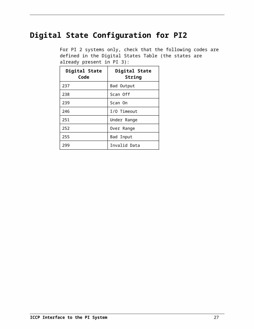
Digital State Configuration for PI2For PI 2 systems only, check that the following codes are defined in the Digital States Table (the states are already present in PI 3):
Digital State Code Digital State String237 Bad Output
238 Scan Off
239 Scan On
246 I/O Timeout
251 Under Range
252 Over Range
255 Bad Input
299 Invalid Data
ICCP Interface to the PI System 19
Interface InstallationOSIsoft recommends that interfaces be installed on PI-API nodes instead of directly on the PI Server node. A PI-API node is any node other than the PI Server node where the PI Application Programming Interface (PI-API) has been installed (see the PI-API Installation Instructions manual). With this approach, the PI Server need not compete with interfaces for the machine’s resources. The primary function of the PI Server is to archive data and to service clients that request data.
After the interface has been installed and tested, Bufserv should be enabled on the PI-API node (once again, see the PI-API Installation Instructions manual). Bufserv is distributed with the PI-API. It is a utility program that provides the capability to store and forward events to a PI Server, allowing continuous data collection when communication to the PI Server is lost. Communication will be lost when there are network problems or when the PI Server is shut down for maintenance, upgrades, backups, or unexpected failures.
In most cases, interfaces on PI-API nodes should be installed as automatic services. Services keep running after the user logs off. Automatic services automatically restart when the computer is restarted, which is useful in the event of a power failure.
The guidelines are different if an interface is installed on the PI Server node. In this case, the typical procedure is to install the PI Server as an automatic service and interfaces as manual services that are launched by site-specific command files when the PI Server is started. Interfaces that are started as manual services are also stopped in conjunction with the PI Server by site-specific command files. This typical scenario assumes that Bufserv is not enabled on the PI Server node. Bufserv can be enabled on the PI Server node so that interfaces on the PI Server node do not need to be started and stopped in conjunction with PI, but it is not standard practice to enable buffering on the PI Server node. See the UniInt End User Document for special procedural information.
Naming Conventions and RequirementsIn the installation procedure below, it is assumed that the name of the interface executable is pi_iccp.exe and that the startup command file is called pi_iccp.bat.
It is customary for the user to rename the executable and the startup command file when multiple copies of the interface are run. For example, one would typically use pi_iccp1.exe and pi_iccp1.bat for interface number 1, pi_iccp2.exe and pi_iccp2.bat for interface number 2, and so on. When an interface is run as a service, the executable and the command file must have the same root name because the service looks for its command-line arguments in a file that has the same root name.
ICCP Interface to the PI System 21
Microsoft DLLsThe following Microsoft DLLs are distributed on the installation CD-ROM. Copy these files to the winnt\system32 directory only if the files in the winnt\system32 directory are older than the files on the CD-ROM.
MSVCIRT.DLL
MSVCRT.DLL
MSVCRT40.DLL
MSVCP50.DLL
MSVCP60.DLL
The following additional Microsoft DLLs are also distributed on the CD-ROM. These DLLs are only used by a debug version of the interface. Copy these files to the Winnt\system32 directory only if the files in the winnt\system32 directory are older than the files on the CD-ROM.
MSVCIRTD.DLL
MSVCRTD.DLL
MSVCP50D.DLL
MSVCP60D.DLL
Interface Directories
The PIHOME Directory TreeThe PIHOME directory tree is defined by the PIHOME entry in the pipc.ini configuration file. This pipc.ini file is an ASCII text file, which is located in the WinNT directory. A typical pipc.ini file contains the following lines:
[PIPC]PIHOME=c:\pipc
the preceding lines define the \pipc directory as the root of the PIHOME directory tree on the C: drive. OSIsoft recommends using \pipc as the root directory name. The PIHOME directory does not need to be on the C: drive.
Interface Installation DirectoryPlace all copies of the interface into a single directory. The suggested directory is:PIHOME\interfaces\pi_iccp\
Replace PIHOME with the corresponding entry in the pipc.ini file.
ICCP Interface to the PI System 22

Interface Installation ProcedureIn the installation procedure below, assume that interface number 1 is being installed and that all copies of the interface will be installed in the same directory.
1. Copy the interface files from the installation media to PIHOME\interfaces\pi_iccp\. Create the directory if necessary.
2. If necessary, rename the command file so that it has the same root name of the executable.
3. Alter the command-line arguments in the .bat file as discussed in this manual.
4. Try to start the interface interactively with the command:pi_iccp.bat
If the interface cannot be started interactively, one will not be able to run the interface as a service. It is easier to debug interactively started processes because error messages are echoed directly to the screen. Once the interface is successfully running interactively, one can try to run it as a service by following the instructions below.
Installing the Interface as an NT ServiceOne can get help for installing the interface as a service at any time with the command:pi_iccp.exe –help
Change to the directory where the pi_iccp1.exe executable is located. Then, consult the following table to determine the appropriate service installation command.
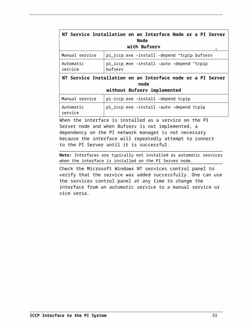
NT Service Installation on an Interface Node or a PI Server Node with Bufserv
Manual service pi_iccp.exe –install –depend “tcpip bufserv”
Automatic service pi_iccp.exe –install –auto –depend “tcpip bufserv”
NT Service Installation on an Interface node or a PI Server nodewithout Bufserv implemented
Manual service pi-iccp.exe –install –depend tcpip
Automatic service pi_iccp.exe –install –auto –depend tcpipWhen the interface is installed as a service on the PI Server node and when Bufserv is not implemented, a dependency on the PI network manager is not necessary because the interface will repeatedly attempt to connect to the PI Server until it is successful.
Note: Interfaces are typically not installed as automatic services when the interface is installed on the PI Server node.
Check the Microsoft Windows NT services control panel to verify that the service was added successfully. One can use the services control panel at any time to change the interface from an automatic service to a manual service or vice versa.
ICCP Interface to the PI System 23

PI-ICCP Tag Import UtilityThe PI-ICCP interface is shipped with a Tag Import Utility (TIU), which reads the data object names from the ICCP server, and creates PI tags based these names and other user settings. The import utility is also useful for creating the startup batch files described in the Startup Command File section.
Installing the Import UtilityThe import utility is shipped on the same installation disks as the interface. The TIU is automatically installed with the PI-ICCP interface.
The import utility must be run on a PC that is capable of running the interface, as described in the section title Hardware and Software. After installation, an icon will be created for the import utility in the “PI System” group on the start menu. To run the import utility, simply click on the icon.
Utility OperationIn order to use the import utility, several steps must be followed:
1. Connect to the ICCP server.2. Set the utility’s tag creation options.3. Import object names from a specific domain.4. Edit the PI tag attributes for the imported names.5. Continue with step 3 until all ICCP objects have been imported.6. Update PI.7. Disconnect from the server.
Optionally, you may also create startup files for each interface with the utility.
The import utility maintains its own log file, using the same runtime logging facilities as the interface. The options for the import utility log file are stored in the configlog.cfg file, which the installation program installs in the import utility’s directory. This configuration file follows the same format as described in Run Time Logging Configuration, and may be edited if you wish. By default, the import utility uses iccpconfig.log as its log file.
Connecting to the ICCP ServerWhen the import utility starts, a window, shown below, will be displayed, prompting you for the server AR name, and the local AR name. These values are the same as those specified for the interface (see Startup Command File). Once these values are entered, clicking the Connect button will allow the utility to attempt to connect to the server.
Note: The utility remains connected to the server until you exit the utility.
ICCP Interface to the PI System 25

Importing Tag NamesOnce connected to the server, the configuration window, shown below, will be displayed. From this window, you will be able to specify the ICCP domain from which to read the tag names, the types of PI tags to create, and some default attributes for the tags.
PI Tag CreationThe PI tag name will always be set to the same name as the ICCP data object name. However, as described in Selecting PI Tag PointTypes for Different ICCP Values, each data value object may require several PI tags to obtain all its values. The import utility will automatically create these tags if the option is selected.
ICCP Interface to the PI System 26

To create the supplementary tags, such as for quality, validity, etc., “check” the appropriate checkbox in the configuration window. In order to differentiate between the main value tag and the supplementary tags, a suffix must be appended to the supplementary tags. You may set this suffix for each supplementary tag type that is created by entering a suffix in the edit box beside the appropriate checkbox. The default suffixes are shown in the diagram of the configuration window.
The default scan class for all imported tags can be set by entering the scan class number in the appropriate edit box. The value you enter for the scan class will be placed in location4 of the PI tag.
If the “Set all tags to Output tags” option is checked, all imported tags will be created as output tags, i.e., location2 will be set to 1. If the “Retrieve all values by Exception” option is checked, all tags will be created as exception-based tags, i.e., location3 will be set to 1.
If the “Discard currently selected tag” option is checked, all previously imported tags will be cleared from the import utility’s memory. NOTE: This will not affect any tags already in PI.
The “Interface ID” and “Point Source” parameters also affect how the PI tags are created. The value in the “Interface ID” option is placed in location1, while the value in the “Point Source” option is placed in the PointSource attribute of the tag.
Cross Referencing PI TagsOnce all the options are set, click the Import Tags button to read the data object names from the ICCP server. When you click this button, you will be presented with two options:
read the tag attributes from both PI and ICCP; and read the tag attributes from ICCP only.
The first option, if selected, causes the interface to cross reference the ICCP tag names with the PI tag names, reading user-modifiable tag attributes from PI. The user-modifiable attributes are items such as the zero, span, interface ID, and other attributes which receive default values.
The following dialog box is displayed to obtain your option:
Note: PI must be running in order to read any existing PI tag attributes.
ICCP Interface to the PI System 27
PI-ICCP Tag Import Utility
Editing PI Tag DataOnce the tags have been imported from the ICCP server, you are able to edit the attributes if you wish. Click the Edit Tags button to display the editing window:
The editing window allows you to edit most of the PI tag attributes required for proper interface operation. The editing window allows you to add or delete tags, copy and paste ranges of values, and modify tag attributes. Each button on the button bar performs one of these functions, as described by “hints” which appear when the mouse is positioned over the button.
Note: The edit window does not provide an “undo” facility.
Adding TagsTo add a new entry to the tag list, click the “Add” button (the button with the plus sign in it). You will be prompted for a new tag name. If a PI server is running, you may select an existing PI tag from the “tag search” dialog (the same one ProcessBook uses).
Edit and Select ModesThe edit window has two modes: edit and select. The mode is determined by clicking the “mode” button. In the edit mode, you may edit the various tag attributes, and copy, cut, and paste any selected text. You cannot, however, select more than a single cell in the grid.
In the select mode, you cannot edit text, but you are able to select any range of cells, and copy, paste, or delete the selection.
Exporting to a Batch FileThe following table depicts the standard dialog box that appears when the Batch File command is executed. The user is prompted to input a file name. The TIU will import incorporate all of the switch information that is currently available in the Main Dialog box.
28
Exiting the TIUUpon selection of the “close” option of the Main Dialog box, the TIU will exit. Before closing, a dialog box will appear prompting the user to save the present settings in the Main dialog box. These settings are stored in C:\winnt\PiIccpGUI.ini file.
Running the Tag Import Utility OfflineThe TIU may be run in “offline” mode, which allows the user to bypass the connection phase to the ICCP server. This option may be desirable if the user wishes to create a large number of tags and has the data types for each of the ICCP objects (in the cross-reference file). The TIU is run offline by typing the following command at a command prompt:
piiccpgui offline
The user will be prompted with a message box informing that he is working without connecting to an ICCP server. He will not be prompted for the AR Server or Client names, and the user must read the tag configuration information from a cross-reference file. Otherwise the session is executed in a manner similar to the online session.
To run the TIU online later, the user must exit the utility and restart the TIU without the “offline” switch.
Note: One of the primary motivation for the “offline” option on the ICCP server is that establishment on of a large number of PI tags can be time consuming as if connected to the ICCP server. This is due to the fact that the TIU will register a separate “get data
ICCP Interface to the PI System 29
PI-ICCP Tag Import Utility
types” (GET_VARDEF) request for each and every PI tag created. For a large number of tags this can take a prohibitively long time.
30
PointSourceThe PointSource is a single, unique character that is used to identify the PI point as a point that belongs to a particular interface. For example, one may choose the letter I to identify points that belong to the PI-ICCP interface. To implement this, one would set the PointSource attribute to I for every PI Point that is configured for the PI-ICCP interface. Then, if one uses /ps=I on the startup-command line of the PI-ICCP interface, the PI-ICCP interface will search the PI Point Database upon startup for every PI point that is configured with a PointSource of I. Before an interface loads a point, the interface usually performs further checks by examining additional PI point attributes to determine whether a particular point is valid for the interface. For additional information, see the /ps argument.
Case-sensitivity for PointSource AttributesIf the interface is running on a PINet node and the Server node is a PI 3 system, use a capital letter (or a case-insensitive character such as a number, a question mark, etc.) for the PointSource attribute when defining points. For all other scenarios, one does not need to be careful with the case of the PointSource.
In all cases, the point source character that is supplied with the /ps command-line argument is not case sensitive. That is, /ps=I and /ps=I are equivalent. One only needs to be careful with the case of the PointSource during point definition, and only if the interface will be running on a PINet node communicating to a PI 3 Server.
PI 2 Server NodesThe following point source characters are reserved on PI 2 systems and cannot be used as the point source character for an interface: C, ?, @, Q, T. Also, if one does not specify a point source character when creating a PI point, the point is assigned a default point source character of L. Therefore, it would be confusing to use L as the point source character for an interface.
Before a PI point with a given point source can be created, the point source character must be added to the PI 2 point source table. For example, if point source I is not defined in the PI 2 point source table, a point with a point source of I cannot be created. This prevents the user from accidentally creating a point with an incorrect point source character.
Defining a Point Source Character in the PI 2 Point Source Table
1. Enter PI by typing the following command from a VMS command prompt: @pisysexe:pi
2. Select the PointSrc option from the menu.
3. Select New from the menu.
4. Assign a point source next to the Code: field. Also, assign minimum and maximum values for the Location1 to Location5 attributes.
Location1 Location2 Location3 Location4 Location5
Minimum 1 0 0 1 0
Maximum 99 1 1 256 7
ICCP Interface to the PI System 31

Location1 Location2 Location3 Location4 Location5
5. Select “Save” from the menu.
PI 3 Server NodesNo point source table exists on a PI 3 Server, which means that points can be immediately created on PI 3 with any point source character. Several subsystems and applications that ship with PI 3 are associated with default point source characters. The Totalizer Subsystem uses the point source character T, the Alarm Subsystem uses G and @, Random uses R, RampSoak uses 9, and the Performance Equations Subsystem uses C. Either do not use these point source characters or change the default point source characters for these applications. Also, if one does not specify a point source character when creating a PI point, the point is assigned a default point source character of L. Therefore, it would be confusing to use L as the point source character for an interface.
ICCP Interface to the PI System 32

PI Point ConfigurationThe PI point is the basic building block for controlling data flow to and from the PI Data Archive. A single point is configured for each measurement value that needs to be archived. Use the point attributes below to define what data to transfer.
ICCP Data Value Object FormatEach “tag” within ICCP is represented as a data value object. A data value object contains the object name, i.e., the tag name, and any values associated with the tag name. Each data value object may contain up to three values:
the value, either an integer, digital state, or real number;
the quality, an 8-bit integer value, with parameters assigned to each bit; and
the change-of-value counter, an integer value representing the number of state changes since the last data read.
Because the quality and digital state values are 8-bit integer values, with every bit or every two bits representing a digital state, the actual number of possible values for each ICCP data value object is six (see Selecting PI Tag PointTypes for Different ICCP Values below).
Since PI data objects maintain only a single value per tag name, multiple PI tags are required to obtain all the values from an ICCP data object. For example, if the value and quality were required from an ICCP object, two PI tags would be required; one to read the value, and one to read the quality.
See the following section for more information on configuring PI tags to receive data from an ICCP server.
General PI Tag Configuration InformationOne PI point (PI tag) must be configured for each ICCP value, quality, or COV counter the user wants to read from or write to. The points can be configured on a PI2 or PI3 home node.
The following table describes the PI point attributes most relevant for use with the PI-ICCP interface. Other attributes not discussed in this manual may be required for proper configuration of the PI point. These include tag, a required attribute naming the PI point, typicalValue, Engunits (engineering units string), rescode (for PI2 only), filterCode, and others. The user may wish to create I/O Rate Tags for each interface. For more information on PI Point configuration see the Data Archive (DA) section of the PI System Manual (for PI2 home nodes) or the PI Data Archive Manual for Windows NT and UNIX (for PI3 home nodes). The attributes listed below are consistent with those used in the Data Archive Manual for PI3.
TagA tag is a label or name for a point. Any tag name can be used in accordance to the normal PI point naming conventions.
ICCP Interface to the PI System 33
PointSourceThe PointSource is a single, unique character that is used to identify the PI point as a point that belongs to a particular interface. All points to be used by the PI-ICCP interface must share a common point source (for example, I). For a PI2 home node, one must edit the point source table to include this PointSource (choose “point source” from the PI2 System main menu). For PI3, the only requirement is to configure the tag with the same PointSource that is defined in the PI_ICCP..bat startup command file. For additional information, see the /ps command-line argument and the “Point Source” section.
PointTypeTypically, device point types do not need to correspond to PI point types. For example, integer values from a device can be sent to floating point or digital PI tags. Similarly, a floating-point value from the device can be sent to integer or digital PI tags, although the values will be truncated.
PI 2 Server NodesScaled real, full-precision real, integer, and digital point types are supported on PI 2 Servers. For more information on the individual point types, refer to the Data Archive (DA) section of PI System Manual I.
The interface supports the PI2 real, digital, and integer point types
PI 3 Server NodesFloat16, float32, int16, int32, digital, string, and blob point types are supported on PI 3 Servers. For more information on the individual point types, see PI Data Archive for NT and UNIX.
The interface supports the PI3 Float16, Float32, Int32, and digital point types
Selecting PI Tag PointTypes for Different ICCP ValuesEach ICCP data value object may hold up to six values. For this reason, several PI tags may be required for each ICCP object, depending on the values that need to be retrieved. The ICCP data value objects may have all or some of the following values:
real value – the value of an analog point; discrete value – an integer value of a point; COV – an integer representing a change of value count; timestamp quality flag – indicates the quality of the timestamp (good/bad); normal value flag – indicates whether the value is within the normal range for
the tag; current source – digital state indicating the source of the object’s value, such as
telemetered or estimated; validity – digital state indicating the validity of the point, with possible values
of: VALID, HELD, SUSPECT, and NOTVALID; and state – a digital state (2 bits) representing an object’s state.
The timestamp quality, normal value, current source, and validity types exist within a single 8-bit integer. Each bit of the integer is mapped to one of these fields. The interface allows you to retrieve the entire 8-bit value, or just the values of specific fields within the integer.
ICCP Interface to the PI System 34

Each PI tag must be configured to retrieve the appropriate type of data from the ICCP object. The specific data to be retrieved is configured by entering the appropriate value in Location5 of the PI tag. Only specific combinations of PI tag type, data value type (location5), and ICCP data type are appropriate. The following table describes the valid combinations for ICCP types and PI tag configurations.
Location5 Value PI Data Type
ICCP Data Types
0 (Value) Real or Integer Any Data Value Object data type, as long as PI type is not integer when ICCP type is real.
1 (Quality) Integer or Digital
Data_RealQ, Data_RealExtended
Data_StateQ, Data_StateExtended
Data_DiscreteQ, Data_DiscreteExtended
2 (COV) Integer Data_RealExtended, Data_StateExtended, Data_DiscreteExtended
3 (T.S. Quality) Digital Data_RealQ, Data_RealExtended
Data_State, Data_StateQ, Data_StateExtended
Data_DiscreteQ, Data_DiscreteExtended
4 (Normal Value) Digital Data_RealQ, Data_RealExtended
Data_State, Data_StateQ, Data_StateExtended
Data_DiscreteQ, Data_DiscreteExtended
5 (Current Source) Digital Data_RealQ, Data_RealExtended
Data_State, Data_StateQ, Data_StateExtended
Data_DiscreteQ, Data_DiscreteExtended
6 (Validity) Digital Data_RealQ, Data_RealExtended
Data_State, Data_StateQ, Data_StateExtended
Data_DiscreteQ, Data_DiscreteExtended
7 (State) Digital Data_State, Data_StateQ, Data_StateExtended
Configuration of PI digital tags representing state values (location5 equal to 7) requires some careful consideration. The values reported by the ICCP server are actually integer values. The user must verify what these values are and to what digital states they are mapped. In one specific example, a particular ICCP implementation passes a 1 representing “Normal” state and a 2 representing an “Alarm” state. The PI digital tag should be configured with a digital set that contains three states corresponding to integer values 0, 1, 2. Three states are required because PI digital sets always begin from 0. The digital strings mapped to these three could be “Invalid” for 0 (since this should never occur), “Normal” for 1, and “Alarm” for 2.
Location1This parameter is used to specify the interface number, which corresponds to the /id=# flag in the pi_iccp.bat file. Valid interface numbers are integer values 1 to 99, inclusive.
ICCP Interface to the PI System 35
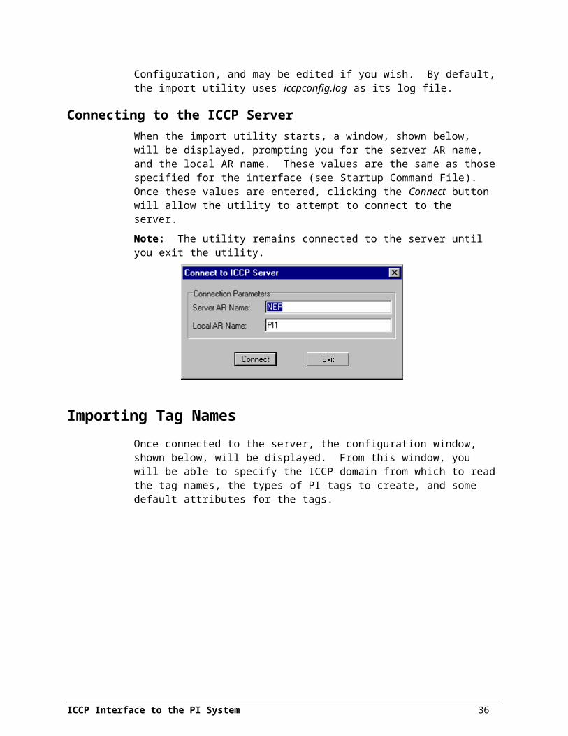
PI Point Configuration
Location2This parameter identifies the I/O type for the tag. If the tag is an output tag, this parameter must be set to 1. For input tags, set this parameter to 0. The Location2 field must always be specified.
Location3Location3 indicates whether the tag’s value should be retrieved as scan-based or exception-based. All tags within a specific scan class (see Location4) must use the same retrieval method. If two tags within the same scan class are configured for different retrieval methods, the scan class will be configured to use the polled retrieval method. Set Location3 to 0 for scan-based tags, and 1 for exception-based tags. For output tags, Location 3 is set to 0.
Location4
Scan-Based InputsFor interfaces that support scan-based collection of data, Location4 defines the scan class for the PI point. The scan class determines the frequency at which input points are scanned for new values. For more information, see the description of the /f flag in the section called “The Startup Command File”.
Trigger-Based Inputs, Unsolicited-Inputs, and Output PointsLocation 4 should be set to zero for these points.
Location5Location5 indicates the tag “type”. The tag type refers to whether the tag contains value, quality, or COV information for the given ICCP object name (see InstrumentTag). See the section “Selecting ICCP Values” for further discussion regarding the values for this attribute. As discussed earlier, the PI tag can store only one attribute of the data object, and it is Location5 that determines which attribute is stored.
0: Value – retrieve the real or integer value from the ICCP object.
1: Quality – retrieve the quality (contains timestamp quality, normal value, current source, and validity) as an 8-bit integer or digital state.
2: COV – retrieve the COV value for the ICCP object.
3: Timestamp Quality – retrieve the timestamp quality for the ICCP object.
4: Normal Value – retrieve the “normal value” flag for the ICCP object.
5: Current Source – retrieve the “current source” digital state for the ICCP object.
6: Validity – retrieve the validity digital state for the ICCP object.
7: State – retrieve the state of the ICCP object.
If a Data_State (or related type) is being retrieved for a PI digital tag, then location5 parameter should be set to 7.
InstrumentTagThis field is used to specify the ICCP data object name and the data object’s domain. The interface supports only named server variables. Unnamed variables are not supported. The maximum length of this field is 32 characters.
36

Different PI tags may reference the same ICCP object name within this field. This allows multiple PI tags to obtain information from a single ICCP data object. Based on the value in Location5, each PI tag may obtain a different value from the ICCP data object.
To specify an ICCP data object name that is VMD specific (i.e., is visible globally, not just within a certain domain), simply enter the object name within this field. For example:
MY_ICCP_OBJECT_NAME
Note that ICCP object names are case sensitive and must be an exact match of the defined name in the ICCP server.
If the data object name is defined within a specific domain, the domain name must be appended to the object name. For example:
MY_ICCP_OBJECT_NAME:DOMAIN_NAME
Note that a colon separates the object and domain names, and that no spaces must exist on either side of the colon.
If the combined length of the ICCP object name and the domain name are greater than 32 characters, the domain name should be placed in the extended descriptor. For the syntax required for placing the object domain name in the extended descriptor see the entry on the ExDesc attribute in this table.
ExDescThis is the extended descriptor attribute. In the PI-ICCP interface, this attribute is limited to 80 characters in length. The five parameters that may be specified in the ExDesc are described below.
ICCP Data TypeThe extended descriptor can be used to specify the ICCP data type for the interface. This specification is optional, but significantly improves the startup time for the interface, as the interface does not need to poll the server for the data type. To specify the ICCP type, use the following format:
TYPE=<ICCP Data Type>where <ICCP Data Type> is the name of the data type. For example:
TYPE=Data_RealQPlease note that the word “TYPE” and the <ICCP Data Type> are both case sensitive. Failure to specify a valid ICCP data type will force the interface into an object-by-object query of the ICCP server, which can be time-consuming at initialization. The data type must match exactly the type as configured on the ICCP server. For example, if the ICCP point is configured as REAL only, with no associated quality or COV, then exdesc must be TYPE=Data_Real. If the ICCP point is configured as REAL with associated quality, COV, source, etc., then exdesc must be TYPE=Data_RealExtended. Each data type has a particular field structure; specifying the wrong type will likely lead to conversion errors since the correct field as specified in Location5 will not be located in the expected position in the Data Value structure.
ICCP Object DomainThe ICCP object domain name may also be placed in the extended descriptor. The syntax required is of the following format:
ICCP Interface to the PI System 37

PI Point Configuration
DOM=<ICCP OBJECT DOMAIN NAME>
Performance PointsFor UniInt-based interfaces, the extended descriptor is checked for the string “PERFORMANCE_POINT”. If this character string is found, UniInt treats this point as a performance point. See the section called “Performance Point Configuration.”
Trigger-Based InputsFor trigger-based input points, a separate trigger point must be configured. An input point is associated with a trigger point by entering a case-insensitive string in the extended descriptor (ExDesc) PI point attribute of the input point of the form:
keyword=<trigger_tag_name>
where keyword is replaced by “event” or “trig” and <trigger_tag_name> is replaced by the name of the trigger point. There should be no spaces in the string. UniInt automatically assumes that an input point is trigger-based instead of scan-based when the keyword=<trigger_tag_name> string is found in the extended descriptor attribute.
An input is triggered when a new value is sent to the Snapshot of the trigger point. The new value does not need to be different than the previous Snapshot value to trigger an input, but the timestamp of the new value must be greater than (more recent than) or equal to the timestamp of the previous value. This is different than the trigger mechanism for output points. For output points, the timestamp of the trigger value must be greater than (not greater than or equal to) the timestamp of the previous value.
A Trigger Tag can be used in conjunction with an input tag. An input tag is a tag for which the I/O type has been set to 0 in Location2. By specifying a Trigger Tag, the associated input tag is scanned after an “event” instead of being scanned at the frequency specified in Location4. See the section entitled “Input Tag Configuration” for essential details on input tags and Trigger Tags.
Multiple Parameters in the Extended DescriptorCommas are used to delimit the various arguments. For example:
TYPE=Data_RealQ, DOM=PI1Specifies a data type of Data_RealQ and a point domain on the ICCP server of PI1. The order in which the Event, TYPE, and DOM parameters are used is not important.
As another example, to specify both a <triggertag> and an ICCP type use the following syntax:
Event=triggertag,TYPE=Data_RealQ
ExcDev, ExcMax, and ExcMinThese fields contain the exception specifications for a tag (see the PI Data Archive manual). If the tag’s values are being retrieved by exception from the ICCP server (see location3), these fields should be set to zero.
Scan By default, the Scan attribute has a value of 1, which means that scanning is turned on for the point. Setting the scan attribute to 0 turns scanning off. If the scan attribute is 0 when the interface starts, SCAN OFF will be written to the PI point. If the scan attribute is changed from 1 to 0 while the interface is running, SCAN OFF will also be written to the PI point after the point edit is detected by the interface.
38
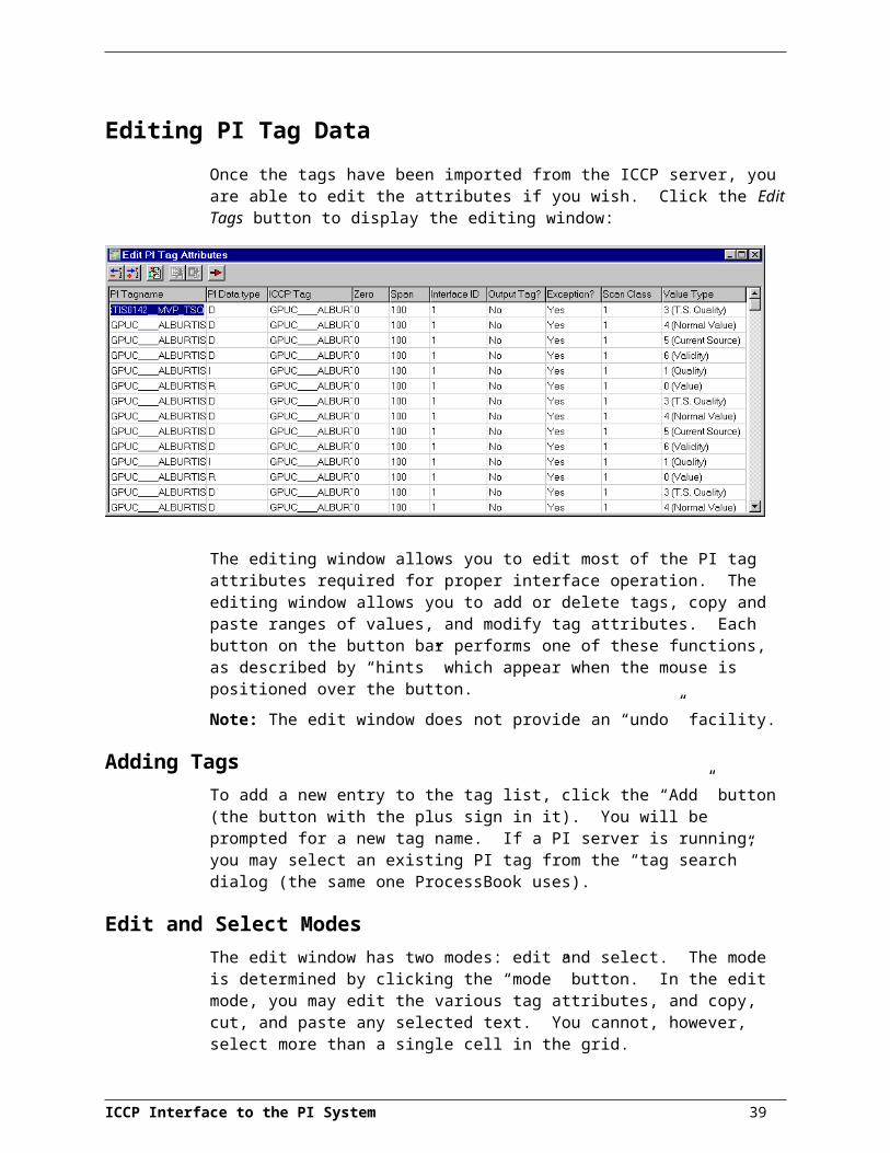
There is one other situation, which is independent of the Scan attribute, where UniInt will write SCAN OFF to a PI point. If a point that is currently loaded by the interface is edited so that the point is no longer valid for the interface, the point will be removed from the interface, and SCAN OFF will be written to the point. For example, if the PointSource of a PI point that is currently loaded by the interface is changed, the point will be removed from the interface and SCAN OFF will be written to the point.
Shutdown
PI 2 Server NodesThe Shutdown attribute is not used if the server node is a PI 2 system. For information on configuring shutdown events for PI 2, see Data Archive (DA) section 4.2.3 of PI System Manual I.
PI 3 Server NodesThe shutdown attribute is used only if the server node is a PI 3 system.
The Shutdown attribute is 1 (true) by default. The default behavior of the PI Shutdown subsystem is to write the SHUTDOWN digital state to all PI points when PI is started. The timestamp that is used for the SHUTDOWN events is retrieved from a file that is updated by the Snapshot Subsystem. The timestamp is usually updated every 15 minutes, which means that the timestamp for the SHUTDOWN events will be accurate to within 15 minutes in the event of a power failure. For additional information on shutdown events, refer to PI Data Archive for NT and UNIX.
Note: The SHUTDOWN events that are written by the PI Shutdown subsystem are independent of the SHUTDOWN events that are written by the interface when the /stopstat=Shutdown command-line argument is specified.
One can disable SHUTDOWN events from being written to PI when PI is restarted by setting the Shutdown attribute to 0 for each point. Alternatively, one can change the default behavior of the PI Shutdown Subsystem to write SHUTDOWN events only for PI points that have their Shutdown attribute set to 0. To change the default behavior, edit the \PI\dat\Shutdown.dat file, as discussed in PI Data Archive for NT and UNIX.
BufservIt is undesirable to write shutdown events when Bufserv is being used. Bufserv is a utility program that provides the capability to store and forward events to a PI Server, allowing continuous data collection when the Server is down for maintenance, upgrades, backups, and unexpected failures. That is, when PI is shut down, Bufserv will continue to collect data for the interface, making it undesirable to write SHUTDOWN events to the PI points for this interface.
SourceTagA SourceTag can be used in conjunction with an output tag. An output tag is a tag for which the I/O type has been set to 1 in Location3. See the section entitled “Output Tag Configuration” for essential details on output tags and SourceTags.
Input Tag ConfigurationInput tags are used to receive data from ICCP nodes. A tag is an input tag if a 0 is specified in Location2. Values are requested from ICCP at a given frequency, by
ICCP Interface to the PI System 39
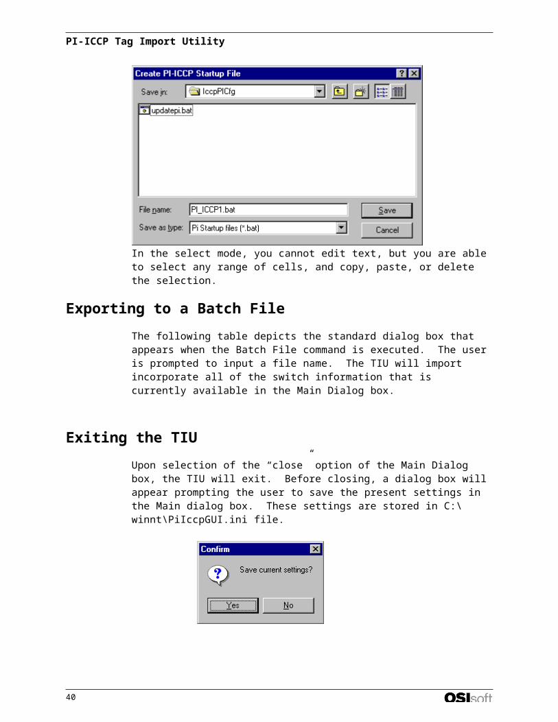
PI Point Configuration
exception, or after an “event,” depending on the configuration of the input tag. The method of obtaining data, i.e., polled versus exception, cannot be changed after the interface has started the transfer sets. Since both polled and exception-based data require the initialization of a transfer set on the ICCP server, any changes to location3 will not take effect until the interface is shut down and restarted.
Configuration 1 (Polled): Once the transfer set is instantiated, the values are reported from ICCP and sent to an input tag at a given frequency. The scan class in the command line specifies this frequency. A given point is linked to a particular scan class via the value specified in Location4 point attribute. Configuration 1 is enabled if no “triggertag” is specified the input tag’s extended descriptor, and the dataset that the tag belongs to is polled.
Configuration 2 (Report by Exception): Values are received from ICCP by exception (i.e. Report by Exception or RBE). Within the ICCP transfer set, the change object and RBE flags are both activated when Location3 in the point is set to a value of 1. Change Object allows for the ICCP point to be reported immediately (i.e., whenever the value changes) and sent to the input PI tag . If the ICCP object is not Change Object enabled, then the change is reported when the interval timeout period passes (as specified by the scan class to which the point belongs). RBE also enables integrity timeout reporting, the period of which is specified with the /ito=# switch in the command line. Configuration 2 is enabled if the dataset that the tag belongs to is exception based. Note: This is the recommended configuration.
Configuration 3: Values are requested from ICCP and sent to an input tag after an event is detected for a “triggertag.” The triggertag is specified in the input tag’s extended descriptor. An event occurs whenever a value reaches the snapshot of the triggertag. The actual snapshot value does not need to change for an event to be triggered. For example, say the current value in the snapshot of a triggertag tag is 51. If a value of 51 is sent to the triggertag again, the value will reach the snapshot if exception testing is turned off, triggering an event.
For all configurations, BAD INPUT (digital state 255) is sent to the input tag if a tag cannot be retrieved by the dataset. Communication errors, such as loss of connection, will result in I/O TIMEOUT being reported by the interface
Dataset CreationAs stated previously, a dataset number must be defined for each tag (see location4). Unfortunately, if the number of tags specified for a specific dataset exceeds the maximum number of tags that the ICCP PDU size supports (see Hardware and Software), the interface will separate the dataset into several segments, called siblings.
The sibling datasets have the same properties as the original dataset, but contain the tags that do not fit in any previous datasets. For example, assume 100 PI tags are configured to use dataset number one (Location4 = 1), but the maximum dataset size for the server is 40 tags. The interface will create three datasets (assuming the interface ID is one):
PI1_DS1 (contains 40 tags)PI1_DS1_Sibling_1 (contains 40 tags)PI1_DS1_Sibling_2 (contains 20 tags)
All datasets and their siblings will be polled at the same frequency if they retrieve data by polling rather than by exception.
40
Performance and ICCP UsageICCP uses the concept of datasets to organize points logically. The interface defines one ICCP dataset for every scan class defined when the interface is started. Output tags are not included in datasets.
Note: To maximize performance, all datasets should be exception based.
Polled datasets retrieve the values for every tag within the dataset at intervals defined on the command line, while exception-based datasets report only values that have changed within the ICCP server.
If a tag appears in more than one dataset, it will be updated at the frequency of the highest frequency dataset, or, if any of the datasets are exception based, the tag will be updated by exception. Though possible, there is no advantage to defining a tag in more than one dataset.
When multiple PI tags are configured for a single ICCP data value object, the scan class for all these tags should be the same; i.e., location4 parameter should be the same. When all tags share the same scan class, the ICCP object will be referenced in a single dataset only. The interface also optimizes the datasets so that an ICCP object will appear only once within a specific dataset. However, if the PI tags do not share the same scan class, the ICCP object will appear in more than one dataset. The interface does not optimize across datasets.
Output TagsOutput points control the flow of data from the PI Data Archive to any destination that is external to the PI Data Archive, such as a PLC or a third-party database. For example, to write a value to a register in a PLC, one would use an output point. Each interface has its own rules for determining whether a given point is an input point or an output point. There is no de facto PI point attribute that distinguishes a point as an input point or an output point.
With respect to the PI-ICCP interface, output tags are used to send commands to ICCP. A tag is an output tag if a one (1) is specified in Location2.
Many ICCP objects have more than a single value associated with them, as described in the section “Selecting PI Tag PointTypes for Different ICCP Values”. Therefore, in order to write to an ICCP data value object, more than a single value may need to be sent to the ICCP server. In order for the interface to write every possible value in an ICCP data object, three PI output tags need to be configured:
a value tag (Location5 = 0);
a quality tag (Location5 = 1); and
a COV tag (Location5 = 2).
If a quality or COV tag is not configured for the ICCP data object, these values will be set to zero when the data object’s value is written. Note that the quality and COV tags need only be configured for ICCP data value object data types that contain quality or COV information.
Writing an ICCP ValueThere are three possible variations of a write to an ICCP object:
1. only a value tag is configured;
ICCP Interface to the PI System 41

PI Point Configuration
2. value and quality tags are configured; and
3. value, quality, and COV tags are configured.
Note: All values are sent to the ICCP server only when the value tag is written to. This implies that you cannot change the quality or COV values without writing the object’s value, even if the value of the object does not change.
When only a value tag is configured, a change in the tag’s value, as described below, is immediately sent to the ICCP server. If the ICCP data object maintains quality or COV information, these values will be set to 0.
When value and quality tags are configured, the quality tag must be written first, followed by the value tag. If the quality tag is not written to, the previously stored value for the quality will be sent to the ICCP server.
When all three tags are configured, the COV and quality tags must be written first, followed by the value tag. This is the same operation as when only the value and quality tags are defined.
Output Tag ConfigurationAs a UniInt-based interface, the PI-ICCP interface sends commands to ICCP only when an event occurs. An event is triggered in one of two ways, depending upon the configuration of the output tag.
Configuration 1 (recommended): In this configuration, a command is written to ICCP when an event is detected for a SourceTag. A SourceTag is associated with an output tag through the output tag’s SourceTag field (see the section entitled “PI Point Definition” above). An output is triggered when a new value is sent to the Snapshot of the trigger point. The new value does not need to be different than the previous value that was sent to the Snapshot to trigger an output, but the timestamp of the new value must be more recent than the previous value. If no error is indicated, then the value that was sent to the trigger point is also written to the output point. If the output is unsuccessful, then an appropriate digital state that is indicative of the failure is usually written to the output point. If an error is not indicated, the output still may not have succeeded because the interface may not be able to tell with certainty that an output has failed. The output tag and the SourceTag should be given the same exception specifications (ExcDev, ExcMin, and ExcMax). Otherwise, values that appear in the snapshot of the SourceTag may not appear in the snapshot of the output tag. The PointType of the output tag and SourceTag do not have to be the same, but data loss could result from differences in precision for different PointTypes.
Configuration 2: In this configuration, a command is written to ICCP when an event is detected for the output tag itself. This configuration is enabled if no SourceTag is defined in the output tag’s SourceTag field. This trigger method may be easier to configure than trigger method 1, however, it has a significant disadvantage. If the output is unsuccessful, there is no tag to receive a digital state that is indicative of the failure, which is very important for troubleshooting.
When do “events” occur? An event occurs whenever a value reaches the snapshot of the SourceTag (configuration 1) or the output tag (configuration 2). The actual value of the snapshot does not need to change to trigger an event. For example, say the current value in the snapshot of a SourceTag tag is 51, and say that exception testing is turned on for the SourceTag. Even if the value of the SourceTag does not change, the exception maximum time for the SourceTag will eventually be exceeded. When this happens, a value of 51 will be sent to the snapshot of the SourceTag, triggering an event that will cause a command to be sent to ICCP. It may be undesirable to send a command under
42
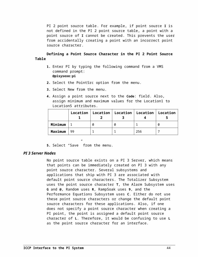
these circumstances. In future versions of the interface, users will be able to configure an output tag so that commands are sent to ICCP only after a change event occurs.
ICCP Interface to the PI System 43

Performance Point ConfigurationOne can configure performance points to monitor the amount of time in seconds that an interface takes to complete a scan for a particular scan class. The closer the scan completion time is to 0 seconds, the better the performance. The scan completion time is recorded to millisecond resolution
Performance point configuration is the same on all operating system platforms. Performance points are configured as follows.
1. Set the extended descriptor to:PERFORMANCE_POINTor to:PERFORMANCE_POINT=interface_idwhere interface_id corresponds to the identifier that is specified with the /id flag on the startup command line of the interface. The character string PERFORMANCE_POINT is case insenstive. The interface_id does not need to be specified if there is only one copy of an interface that is associated with a particular point source.
2. Set Location4 to correspond to the scan class whose performance is to be monitored. For example, to monitor scan class 2, set Location4 to 2. See the /f flag for a description of scan classes.
3. Set the PointSource attribute to correspond to the /ps flag on the startup command line of the interface.
4. Set the PointType attribute to float32.
ICCP Interface to the PI System 45
I/O Rate Tag ConfigurationAn I/O Rate point can be configured to receive 10-minute averages of the total number of exceptions per minute that are sent to PI by the interface. An exception is a value that has passed the exception specifications for a given PI point. Since 10-minute averages are taken, the first average is not written to PI until 10 minutes after the interface has started. One I/O Rate tag can be configured for each copy of the interface that is in use.
Monitoring I/O Rates on the Interface NodeFor NT and UNIX nodes, the 10-minute rate averages (in events/minute) can be monitored with a client application such as ProcessBook.
Configuring the PI Point on the PI Server
PI 2 Server NodesA listing of the I/O Rate Tags that are currently being monitored can be obtained with the command:@PISysDat:IOMonitor.com
Create an I/O Rate Tag using one of the existing I/O Rate Tags as a template.
PI 3 Server NodesCreate an I/O Rate Tag with the following point attribute values.
Attribute ValuePointSource L
PointType float32
Compressing 0
ExcDev 0
Configuring on the Interface NodeFor the following examples, assume that the name of the PI tag is pi_iccp001, and that the name of the I/O Rate on the home node is pi_iccp001.
1. Edit/Create a file called iorates.dat in the PIHOME\dat directory. The PIHOME directory is defined either by the PIPCSHARE entry or the PIHOME entry in the pipc.ini file, which is located in the \WinNT directory. If both are specified, the PIPCSHARE entry takes precedence.
Since the PIHOME directory is typically C:\PIPC, the full name of the iorates.dat file will typically be C:\PIPC\dat\iorates.dat.
Add a line in the iorates.dat file of the form:pi_iccp001, x
ICCP Interface to the PI System 47

where pi_iccp001 is the name of the I/O Rate Tag and x corresponds to the first instance of the /ec=x flag in the startup command file. X can be any number between 2 and 34 or between 51 and 200, inclusive. To specify additional rate counters for additional copies of the interface, create additional I/O Rate tags and additional entries in the iorates.dat file. The event counter, /ec=x, should be unique for each copy of the interface.
2. Set the /ec=x flag on the startup command file of the interface to match the event counter in the iorates.dat file.
The interface must be stopped and restarted in order for the I/O Rate tag to take effect. I/O Rates will not be written to the tag until 10 minutes after the interface is started.
ICCP Interface to the PI System 48

Startup Command FileCommand-line arguments can begin with a / or with a -. For example, the /ps=I and –ps=I command-line arguments are equivalent.
For NT, command file names have a .bat extension. The NT continuation character (^) allows one to use multiple lines for the startup command. The maximum length of each line is 1024 characters (1 kilobyte). The number of flags is unlimited, and the maximum length of each flag is 1024 characters.
Note: The UniInt End User Document includes details about other command line parameters, which may be useful.
Command-Line Parameters
Parameter Description/ln=nnn
requiredSpecifies the local machine’s AR name (where nnn is replaced with the AR name). This parameter is required and has no default value.
/sv=nnn
requiredSpecifies the server’s AR name (where nnn is replaced with the AR name). This parameter is required and has no default value and is required.
As of version 1.3, this command line switch is designates only the first server that will be tried. Subsequent server ARNames, enabled for switchover, are specified in the pi_iccp.ini file. The first one must be specified here.
/dom=ddd
required for each scan class defined
Specifies a domain name for a dataset. Datasets are defined by the scan classes defined on the command line (see /f). There is a one-to-one correspondence between the order of datasets and the order of domain names. For example, assume the following parameters appear on the command line:
/f=00:01:00 /f=00:00:30 /dom=ICCP /dom=FRED
The first dataset would be defined with a polling period of 1 minute, and would be created in the “ICCP” domain. The second dataset would be defined with a polling period of 30 seconds, and would be created in the “FRED” domain.
For datasets that are to be defined as VCC specific (i.e., globally visible and not in a specific domain), simply leave the domain name blank. For example:
/f=00:01:00 /f=00:00:30 /dom= /dom=FRED
The first dataset would now be created in the global domain (VMD specific).
The indicated domain of the data set should be the domain in which the data set and its associated transfer set are created, not necessarily the domain in which the point resides. The originating domain of the point is indicated in the instrumenttag point attribute. For many cases, the domain where the transfer set is created is the name of the local domain set up with the SISCO Stack Configuration utility. For example, if the local domain is defined as PI and the ICCP server’s domain is defined as NEP, then the user would configure a scan
ICCP Interface to the PI System 49
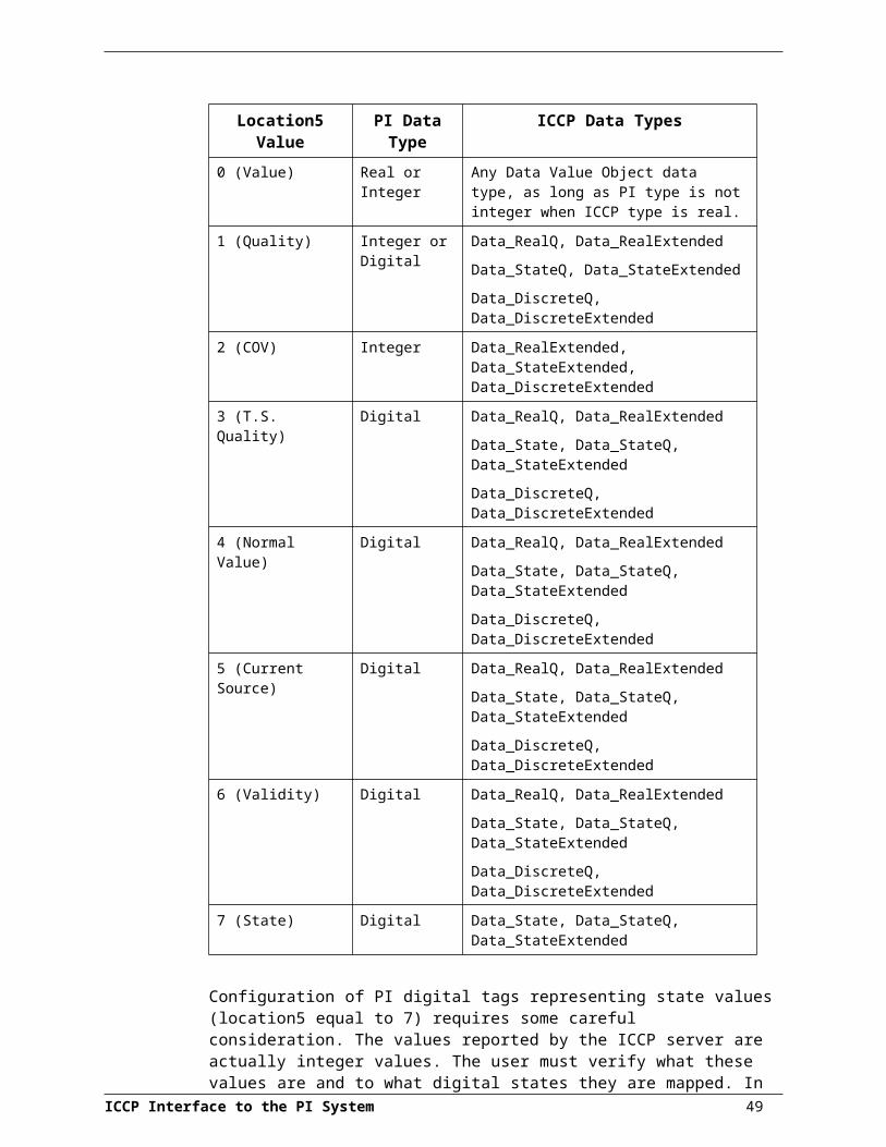
Parameter Descriptionclass with /dom=PI.
While exception-based tags are not scanned at any fixed frequency, the user should set all exception-based tags to the same scan class, with the same location4 parameter reserved only for exception-based tags. For example, the following could exist in the startup file:
/f=00:01:00 /f=00:02:00 /f=00:02:00 /dom=PI /dom=PI /dom=PI
The first scan class could be reserved only for exception-based tags, while the next two scan classes would actually be requested at regular intervals.
Note that no spaces can precede or follow the equal sign.
/ito=mm
optional
Specifies the integrity time-out interval (where mm is replaced with a time in minutes). For datasets that are exception-based, this value specifies how often all values within the dataset are explicitly read from the ICCP server. The integrity time-out value has no effect on polled datasets, as their values are explicitly read based on their polling period. If the /ito switch is not used, then the default value is 10 minutes (i.e. equivalent to /ito=10).
/pdu
optional
Enables low-level PDU (Packet Data Unit) logging. PDU logging uses the “.\iccp_pdu.log” file to record low-level communication between the server and the interface. If the interface is started in interactive mode, the file is created in the directory where the interface executable resides. If the interface is started as a service, the file is created in \winnt\system32. This should only be turned on for debugging purposes.
/L=fff
optional
This parameter specifies the logging configuration file. “fff” is the full path and name of the log configuration file (e.g. “c:\Program Files\pipc\pi_iccp1\log.ini”). The interface provides logging facilities beyond the standard PI logging. See the section on Appendix C: Runtime Logging, later in this manual for a full explanation.
/PT
optional
Forces the interface always to use the PI server’s time for timestamps, even if the ICCP data value objects contain timestamps. This parameter is recommended.
/ebt=#
optional
This switch defines the Exception Buffer Time, defined as the time that the ICCP server buffers an exception before sending to the interface, to minimize packet traffic. The recommended wait time is 5 – 10 seconds. The parameter passed is in seconds and the default is 0 seconds.
/sd=<server type>
optional
Allows the user to set the server section that is accessed for ICCP data type definitions in the pi-iccp.ini file. The default is Siemens.
/mdo=#
optional
This switch sets the maximum number of data objects that a single data set can hold. The lower of this parameter, the dynamically calculated maximum number, and the actual number of data objects defines the size of the data sets generated by the interface. The default is to ignore this parameter and take the lowest of the dynamically calculated maximum and the actual number of objects present to generate a data set.
ICCP Interface to the PI System 50
Parameter Description/ch=#
optional
This switch allows the specification of a particular channel in the OSI stack for communication. This allows for multiple instances of the interface to run on the same box. The default value is 0. More than one interface cannot operate properly on the same stack channel.
/tle=#
optional
The Time Limit for Execution switch is used to specify a TLE that is different than the default 120,000 msec. This parameter is in milliseconds.
/sito=#
optional
This switch sets the OSI Stack Idle Time Out for TCP/IP support. This is the maximum amount of time that the Stack will be unresponsive. The default is 300 seconds. Generally, it is not recommended that the user alter this value except as a temporary method of allowing the interface to compensate for network lag elsewhere in the system. This setting applies only to associations that use TCP/IP in the OSI Stack.
/mcsi=#
optional
This switch sets the maximum number of communication service events that the interface will process before freeing up process resources for other tasks. Since the SISCO OSI stack queue defaults to 10, which is the default value for this switch, the user is strongly recommended not to change the default behavior.
/rec
optional
This switch forces the interface to attempt to query the ICCP server for its data value objects list every time it establishes a connection. With this list, the interface attempts to reconcile all PI points that the interface monitors to check if the ICCP object exists on ICCP server before attempting to create datasets with that data value object. The interface queries both the VMD and the association domain (as defined in the bilateral table). Generally speaking, this switch is recommended. However, the user should note that there can be a performance hit associated with large domain lists.
/nsq
optional
(Version 1.8.10)
The /nsq switch (No State Quality) which allows the user to specify that the interface will not save the highest 2 bits of the quality byte (which are the state). That is, if location 5 of a PI Point specifies to save the quality byte (a value of “1”) then the use of this switch will force the interface to save only the lowest six bits of the quality byte (I.e. the Normal, Validity, Source, and Timestamp Quality portions of the quality byte).
/ps=x
required
The /ps flag specifies the point source for the interface. X is not case sensitive and can be any single character. For example, /ps=P and /ps=p are equivalent.
The point source that is assigned with the /ps flag corresponds to the PointSource attribute of individual PI Points. The interface will attempt to load only those PI points with the appropriate point source.
/id=x
optional
The /id flag is used to specify the interface identifier.
The interface identifier is a string that is no longer than 9 characters in length. UniInt concatenates this string to the header that is used to identify error messages as belonging to a particular interface. See the section called “Error and Informational Messages” for more information, page 67.
UniInt always uses the /id flag in the fashion described above. This
ICCP Interface to the PI System 51
Startup Command File
Parameter Descriptioninterface also uses the /id flag to identify a particular interface copy number that corresponds to an integer value that is assigned to Location1. For this interface, one should use only numeric characters between 1 and 99 in the identifier. For example,
/id=1
/f=SSor/f=SS,SSor /f=HH:MM:SSor/f=HH:MM:SS,hh:mm:ss
Required for reading scan-based inputs
The /f flag defines the time period between scans in terms of hours (HH), minutes (MM), and seconds (SS). The scans can be scheduled to occur at discrete moments in time with an optional time offset specified in terms of hours (hh), minutes (mm), and seconds (ss). If HH and MM are omitted, then the time period that is specified is assumed to be in seconds.
Each instance of the /f flag on the command line defines a scan class for the interface. There is no limit to the number of scan classes that can be defined. The first occurrence of the /f flag on the command line defines the first scan class of the interface, the second occurrence defines the second scan class, and so on. PI Points are associated with a particular scan class via the Location4 PI Point attribute. For example, all PI Points that have Location4 set to 1 will receive input values at the frequency defined by the first scan class. Similarly, all points that have Location4 set to 2 will receive input values at the frequency specified by the second scan class, and so on.
Two scan classes are defined in the following example:/f=00:01:00,00:00:05 /f=00:00:07or, equivalently:/f=60,5 /f=7The first scan class has a scanning frequency of 1 minute with an offset of 5 seconds, and the second scan class has a scanning frequency of 7 seconds. When an offset is specified, the scans occur at discrete moments in time according to the formula:
scan times = (reference time) + n(frequency) + offset
where n is an integer and the reference time is midnight on the day that the interface was started. In the above example, frequency is 60 seconds and offset is 5 seconds for the first scan class. This means that if the interface was started at 05:06:06, the first scan would be at 05:06:10, the second scan would be at 05:07:10, and so on. Since no offset is specified for the second scan class, the absolute scan times are undefined.
The definition of a scan class does not guarantee that the associated points will be scanned at the given frequency. If the interface is under a large load, then some scans may occur late or be skipped entirely. See the section called “Performance Point Configuration” for more information on skipped or missed scans.
Subsecond and Wall Clock scheduling are not supported in the PI-ICCP interface since the ICCP server is responsible for transfer of information to the PI-ICCP interface and there are no parameters which allow the specification of these options in the data transfer.
/host=host:port
optional
The /host flag is used to specify the PI Home node. Host is the IP address of the PI Sever node or the domain name of the PI Server node. Port is the port number for TCP/IP communication. The port is always 5450 for a PI 3 Server and 545 for a PI 2 Server. It is
52

Parameter Descriptionrecommended to explicitly define the host and port on the command line with the /host flag. Nevertheless, if either the host or port is not specified, the interface will attempt to use defaults.
Defaults:
The default port name and server name is specified in the pilogin.ini or piclient.ini file. The piclient.ini file is ignored if a pilogin.ini file is found. Refer to the PI-API Installation Instructions manual for more information on the piclient.ini and pilogin.ini files.
Examples:The interface is running on a PI-API node, the domain name of the PI 3 home node is Marvin, and the IP address of Marvin is 206.79.198.30. Valid /host flags would be:/host=marvin /host=marvin:5450 /host=206.79.198.30/host=206.79.198.30:5450
/stopstator/stopatat=digstate
default:/stopstat=”Intf shut”
optional
If the /stopstat flag is present on the startup command line, then the digital state I/O Timeout will be written to each PI Point when the interface is stopped.
If /stopstat=digstate is present on the command line, then the digital state, digstate, will be written to each PI Point when the interface is stopped. For a PI 3 Server, digstate must be in the system digital state table. For a PI 2 Server, where there is only one digital state table available, digstate must simply be somewhere in the table. UniInt uses the first occurrence in the table.
If neither /stopstat nor /stopstat=digstate is specified on the command line, then no digital states will be written when the interface is shut down.
Examples:/stopstat=”Intf shut”
The entire parameter is enclosed within double quotes when there is a space in digstate.
/ec=x
optional
The first instance of the /ec flag on the command line is used to specify a counter number, x, for an I/O Rate point. If x is not specified, then the default event counter is 1. Also, if the /ec flag is not specified at all, there is still a default event counter of 1 associated with the interface. If there is an I/O Rate point that is associated with an event counter of 1, each copy of the interface that is running without /ec=x explicitly defined will write to the same I/O Rate point. This means that one should either explicitly define an event counter other than 1 for each copy of the interface or one should not associate any I/O Rate points with event counter 1. Configuration of I/O Rate points is discussed in the section called “I/O Rate Tag Configuration,” p. 47.
ICCP Interface to the PI System 53
Startup Command File
Parameter Description/sio
optional
The /sio flag stands for “suppress initial outputs.” The flag applies only for interfaces that support outputs. If the /sio flag is not specified, the interface will behave in the following manner.
When the interface is started, the interface determines the current Snapshot value of each output tag. Next, the interface writes this value to each output tag. In addition, whenever an individual output tag is edited while the interface is running, the interface will write the current Snapshot value to the edited output tag.
This behavior is suppressed if the /sio flag is specified on the command line. That is, outputs will not be written when the interface starts or when an output tag is edited. In other words, when the /sio flag is specified, outputs will only be written when they are explicitly triggered.
/q
optional
When the /q flag is present, Snapshots and exceptions are queued before they are sent to the PI Server node.
Non-Extended API mode behavior:
The maximum queue size is 255 bytes for a PI 3 Server and 36 bytes for a PI 2 Server. For example, if the interface is running on a UNIX node and is communicating to a PI 2 Server, then the maximum queue size is 36. The queue is flushed between scans if it is not filled.
When the /q flag is specified in non-extended API mode, the PI-API sends integer values as 16-bit integers instead of 32-bit integers. Therefore, integer points will be limited to values between 0 and 32767. Values higher than 32767 need to be sent to floating-point PI tags.
Sample pi_iccp.bat FileThe following is an example file:REMREM pi_iccp.batREMREM --------------------------------------------------------------REMREM Sample startup file for the ICCP Interface to the PI System.REM The command-line parameters are included here as REM documentation.REMREM --------------------------------------------------------------REMREM Required command-line parametersREM /dom=ddd ICCP Domain specification for dataset creationREM A domain specification is required for eachREM Scan Class specified (i.e. each /f requires a REM corresponding /dom parameter)REM /f=hh:mm:ss[,hh:mm:ss] Scan frequency[,offset]
54

REM /ln=nnn Local Node ARName specificationREM /host=host:port Specifies PI home nodeREM /ps=x Point source characterREM /sv=nnn SerVer ARName specificationREMREM Optional command-line parametersREM /ch=# OSI stack communcations Channel (default 0)REM /ebt=# Exception Buffer Time (default 0 seconds)REM /ec=# I/O rate counter for the interfaceREM /id=x Interface identifier up to 9 charactersREM /ito=# Integrity Time Out value (default 10 minutes)REM /L=fff Full path and name specification for applicationREM specific log (see Annex C for more detail)REM /maxstoptime=# Max Stop Time allowed for REM NT service shutdownREM /mcsi=# Max # of Communcation REM Service Iterations REM (default 10 events)REM /mdo=# Max # of Data Objects REM (default dynamic calc)REM /pt Use PI Time for all timestampsREM /q Enable queuing of data events sent to PI REM (recommended)REM /rec Force reconcillation of PI tag list and REM ICCP data value list upon (re-)connectionREM /sd=<server_type> ICCP server type (for TDL definitions, REM default Siemens)REM /sio Suppress Initial OutputsREM /stopstat=state Interface Shutdown Digital State REM (default Intf_Shut)REM /tle=# Time to Live for Execution for ICCP requestsREM (default 120,000 milliseconds)REMREM Optional command-line parameters for debugging purposes onlyREM /pdu Enables MMS pdu loggingREM /sn Forces snapshot reporting REM (bypasses exception testing)REMREM Sample command lineREM pi_iccp1 /ec=12 /id=1 /host=localhost:5450 ^REM /f=00:00:15 /f=00:00:20 /dom=PI /dom=PI ^REM /ps=I /sv=NEP1 /ln=PI1 /ito=10 /sd=Siemens ^REM /mdo=60 /ebt=10 /tle=60000 /recREMREM --------------------------------------------------------------
ICCP Interface to the PI System 55
Startup Command File
PI_ICCP.ini FileIn addition to the start-up .bat file, the PI_ICCP.ini file is an initialization file that contains much of the start up information for the PI-ICCP Interface. One of the reasons that the *.ini file is used is because of the 1024 character limit on the command line that may be input in the pi_iccp#.bat file. There are three main parts:
1) Bilateral Table information
2) Server Data Type Definitions
3) Switchover Server AR Names
Bilateral Table InformationThe PI-ICCP Interface is not a true ICCP Server, but acts as an intermediary to interpret the ICCP data formats (and reports) for input into the PI Archive. In order to establish an association with the ICCP server, a transfer of Bilateral Table (BT) information is required. Within the “Bilateral Table” section of the pi_iccp.ini file, the major and minor versions, the remote and local domains, and the Bilateral Table ID are all included. These must be made to match the BT information from the ICCP server. The item LocalDomain should be set with the name of the ICCP server to which the interface will be connecting. The domain name is not the AR Name or the hostname, but the actual domain name as listed on the ICCP server. The RemoteDomain item should be set with the name selected for the local domain upon which the PI-ICCP interface resides. This name should have been configured using the SISCO Stack Configuration utility. The local and remote designations can be confusing, since they appear intuitively to be reversed. The idea is that the pi_iccp.ini mimics the bilateral table as it exists on the ICCP server. From the perspective of the ICCP server, the PI-ICCP machine is the remote domain. The BilateralTableID should be set to the table ID for the ICCP server. The same ID should be used in the ICCP server configuration file for the client domain. For example, if the local domain referring to the interface’s domain is named PI and the ICCP server’s domain is named ICCP, then Bilateral Table Ids for both of the entries in the configuration file should be the same.
An example of the contents of the pi_iccp.ini file follows:
[Bilateral Table]VersionMajor = 1996VersionMinor = 8LocalDomain = PGEEMSRemoteDomain = PIBilateralTableID = 1.0; Whether BT Identification is required from ICCP Server; 0 = false, 1 = trueSendBTInfo = 1
[Siemens]; TDL for the Siemens serverData_Real = ‘Float’Data_State = ‘Bstring8’Data_Discrete = ‘Long’Data_Flags = ‘Bstring8’Data_TimeStamp = ‘Gtime’COV_Counter = ‘Ushort’Data_RealQ = ‘{(Value)Float,(Flags)Bstring8}’Data_StateQ = ‘Bstring8’
56
Data_DiscreteQ = ‘{(Value)Long,(Flags)Bstring8}’Data_RealQTimeTag = ‘{(Value)Float,(TimeStamp)Long,(Flags)Bstring8}’Data_StateQTimeTag = ‘{(TimeStamp)Long,(Flags)Bstring8}’Data_DiscreteQTimeTag = ‘{(Value)Long,(TimeStamp)Long,(Flags)Bstring8}’Data_RealExtended = ‘{(Value)Float,(TimeStamp)Long,(Flags)Bstring8,(COV)Ushort}’Data_StateExtended = ‘{(TimeStamp)Long,(Flags)Bstring8,(COV)Ushort}’Data_DiscreteExtended = ‘{(Value)Long,(TimeStamp)Long,(Flags)Bstring8,(COV)Ushort}’
; Data types for interoperabilityBilatTableID = ‘Vstring32’TASE2Version = ‘{Short, Short}’SupportedFeatures = ‘Bstring12’; Data types for creating transfer setsMMSObjectName = ‘{Ubyte,Vstring32,Vstring32}’DSConditions” = ‘Bstring05’DSTransferSet = ‘{<@VMD:MMSObjectName>,Long,Short,Short,Short,Short,<@VMD:DSConditions>,Bool,Bool,Bool,Bool,Short}’
[ABBSpider]; TDL for the ABB Spider serverData_Real = ‘Float’Data_State = ‘Bstring08’Data_Discrete = ‘Long’Data_Flags = ‘Bstring8’Data_TimeStamp = ‘Long’COV_Counter = ‘Ushort’Data_RealQ = ‘{<@VMD:Data_Real>,<@VMD:Data_Flags>}’Data_StateQ = ‘Bstring08’Data_DiscreteQ = ‘{<@VMD:Data_Discrete>,<@VMD:Data_Flags>}’Data_RealQTimeTag = ‘{<@VMD:Data_Real>,<@VMD:Data_TimeStamp>,<@VMD:Data_Flags>}’Data_StateQTimeTag = ‘{<@VMD:Data_TimeStamp>,Bstring8}’Data_DiscreteQTimeTag = ‘{<@VMD:Data_Discrete>,<@VMD:Data_TimeStamp>,<@VMD:Data_Flags>}’Data_RealExtended = ‘{<@VMD:Data_Real>,<@VMD:Data_TimeStamp>,<@VMD:Data_Flags>,<@VMD:COV_Counter>}’Data_StateExtended = ‘{<@VMD:Data_TimeStamp>,<@VMD:Data_Flags>,<@VMD:COV_Counter>}’Data_DiscreteExtended = ‘{<@VMD:Data_Discrete>,<@VMD:Data_TimeStamp>,<@VMD:Data_Flags>,<@VMD:COV_Counter>}’; Data types for interoperabilityBilatTableID = ‘Vstring32’TASE2Version = ‘{Short, Short}’SupportedFeatures = ‘Bstring12’; Data types for creating transfer setsMMSObjectName = ‘{Ubyte,Vstring32,Vstring32}’DSConditions” = ‘Bstring05’DSTransferSet = ‘{<@VMD:MMSObjectName>,Long,Short,Short,Short,Short,<@VMD:DSConditions>,Bool,Bool,Bool,Bool,Short}’; Server Data for Switchover between Server Nodes[SwitchoverServers]Number = 1;ServerARNAME1 = EMS2ServerARNAME2 = EMS1
ICCP Interface to the PI System 57

Startup Command File
Server Data Type DefinitionsSince there is some ambiguity in the ICCP specifications dealing with the formatting of data types, it is necessary to specify the exact data type definitions with respect to each ICCP server type. The entries in the pi_iccp.ini files that are accessed is determined by the server type that is specified in the command line with the /sd=<server type> switch. Remember, if this switch is not used, the default is to assume /sd=Siemens. The ABBSpider and ABBEMSYS implementations should be identical. The entries with Server Data Type Domain are for the type definitions of the ICCP object data types, the interoperability objects, and the transfer set objects.
Switchover Server AR NamesAt the end of the pi_iccp.ini file is the SwitchoverServers item. This section allows the specification of one or more servers to connect to, in the event of a switchover. The total number of additional servers must be specified in the pi_iccp.ini file. One server AR Name must be specified in the start-up command file (pi_iccp#.bat), all others are specified in the pi_iccp.ini file . The entries in the pi_iccp.ini file must include the AR Names of the ICCP servers that will fulfill the role of switchover servers. Up to 7 additional servers may be specified (i.e. 8 total).
The list generated starts from serverARName1. However, the first server in the list is specified in the startup command file (*.bat) with the /sv=nnn switch. All subsequent servers are specified in the *.ini file. Therefore, the first non-commented line for switchover server names should be ServerARNAME2=<ARName>.
Generally, the entries should not include the AR Name that is used in the interface startup file. If the AR Name in the start-up file is also used in the pi_iccp.ini file, the connection to that server will be tested twice. The interface merely constructs a round-robin list that is cycled through until an active association is established. In the example above, the switchover server’s AR Name, as configured using the SISCO OSI Stack Configuration utility, is EMS1. This assumes that the startup script (pi_iccp#.bat) uses /sv=EMS2, indicating that the primary server is EMS2.
58

Interface Node ClockOn NT, the correct settings for the time and time zone should be set in the Date/Time control panel. If local time participates in Daylight Savings, from the control panel, configure the time to be automatically adjusted for Daylight Savings Time. The correct local settings should be used even if the interface node runs in a different time zone than the PI Server node.
Make sure that the TZ environment variable is not defined. The currently defined environment variables can be listed by going to Start | Settings | Control Panel, double clicking on the system icon, and selecting the environment tab on the resulting dialog box. Also, make sure that the TZ variable is not defined in an autoexec.bat file. When the TZ variable is defined in an autoexec.bat file, the TZ variable may not appear as being defined in the System control panel even though the variable is defined. Admittedly, autoexec.bat files are not typically used on NT, but this does not prevent a rogue user from creating such a file and defining the TZ variable unbeknownst to the System Administrator.
ICCP Interface to the PI System 59

SecurityIf the home node is a PI 3 Server, the PI Firewall Database and the PI Proxy Database must be configured so that the interface is allowed to write data to the PI Data Archive. See “Modifying the Firewall Database” and “Modifying the Proxy Database” in the PI Data Archive Manual.
If the home node is a PI 2 Server, the read/write permissions should be set appropriately in the pisysdat:piserver.dat file on the PI 2 home node. For more information on setting permissions on PI 2, see the pibuild:piserver.txt file on the PI 2 home node.
If the interface cannot write data to a PI 3 Server because it has insufficient privileges, a –10401 error will be reported in the pipc.log file. If the interface cannot send data to a PI2 Serve, it writes a –999 error. See the section “Appendix A: Error and Informational Messages” for additional information on error messaging.
ICCP Interface to the PI System 61
Starting / Stopping the InterfaceThis section describes starting and stopping the interface once it has been installed as a service. See the UniInt End User Document to run the interface interactively.
Starting Interface as a ServiceIf the interface was installed a service, it can be started from the services control panel or with the command:
pi_iccp.exe –startA message will be echoed to the screen informing the user whether or not the interface has been successfully started as a service. Even if the message indicates that the service started successfully, make sure that the service is still running by checking in the services control panel. There are several reasons that a service may immediately terminate after startup. One is that the service may not be able to find the command-line arguments in the associated .bat file. For this to succeed, the root name of the .bat file and the .exe file must be the same, and the .bat file and the .exe file must be in the same directory. If the service terminates prematurely for whatever reason, no error messages will be echoed to the screen. The user must consult the pipc.log file for error messages. See Appendix A: Error and Informational Messages for additional information.
Stopping Interface Running as a ServiceIf the interface was installed a service, it can be stopped at any time from the services control panel or with the command:
pi_iccp.exe –stopThe service can be removed by:
pi_iccp.exe –remove
ICCP Interface to the PI System 63
BufferingFor complete information on buffering, please refer to the ICCP Interface to the PI System.
PI-API Node buffering consists of a buffering process which runs continuously on the local node, a PI-API library whose calls can send data to this buffering process, and a utility program for examining the state of buffering and controlling the buffering process. Buffering is enabled through the use of a configuration file, piclient.ini. Unless this file is modified to explicitly enable buffering, the PI-API will not buffer data, sending data directly to the home node.
There are no additional steps needed to install buffering after installing the PI-API. The delivered PI-API library supports both buffered and un-buffered calls.
Note: When buffering is configured to be on, the bufserv process must be started before other programs using the PI-API, so that these programs can access the shared buffering resources. Any program that makes a connection to a PI Server has this requirement even if it does not write to PI.
Configuration of buffering is achieved through entries in the piclient.ini file. The file is found in the dat subdirectory of the PIHOME directory (typically c:\pipc\dat) under Windows NT. This file follows the conventions of Microsoft Windows initialization files with sections, keywords within sections, and values for keywords. All buffering settings are entered in a section called [APIBUFFER]. To modify settings, simply edit the piclient.ini file in a text editor (e.g. Notepad on Windows) to the desired values.
The following settings are available for buffering configuration:
Keywords Values Default
Description
BUFFERING 0,1 0 Turn off/on buffering. OFF = 0, ON = 1,
PAUSERATE 0 – 2,000,000 2 When buffers are empty the buffering process will wait for this long before attempting to send more data to the home node (seconds)
RETRYRATE 0 – 2,000,000 120 When the buffering process discovers the home node is unavailable it will wait this long before attempting to reconnect (seconds)
MAXFILESIZE 1 – 2,000,000 100,000 Maximum buffer file size before buffering fails and discards events. (Kbytes)
MAXTRANSFEROBJS
1 – 2,000,000 500 Maximum number of events to send between each SENDRATE pause.
BUF1SIZE 64 – 2,000,000
32768 Primary memory buffer size. (bytes)
BUF2SIZE 64 – 2,000,000
32768 Secondary memory buffer size. (bytes)
SENDRATE 0 – 2,000,000 100 The time to wait between sending up to MAXTRANSFEROBJS to the server
ICCP Interface to the PI System 65
(milliseconds)
In addition to the [APIBUFFER] section, the [PISERVER] section may be used to define the default PI server and an optional time offset change that may occur between the client and server.
Keywords Values Default DescriptionPIHOMENODE string none Default server for UNIX. Windows
default server is in pilogin.ini
DSTMISMATCH 0 – 2,000,000 0 The time that the server and client local time offset is allowed to jump. Typically, 3600 if the nodes are in time zones whose DST rules differ (seconds)
Example piclient.ini FileOn Windows NT the default server information is stored in the pilogin.ini file so the piclient.ini would only have the [APIBUFFER] section. The BUFFERING=1 indicates that buffering is on. The MAXFILESIZE entry in Kbytes of 100000 allows up to 100 Megabytes of data storage. Do not use commas or other separators in the numeric entries. The retry rate is set to 600 seconds meaning wait 10 minutes after losing a connection before retrying.
On NT a piclient.ini file might look like:[APIBUFFER]BUFFERING=1MAXFILESIZE=100000; The PI-API connection routines have a 1 minute default timeout.RETRYRATE=600
ICCP Interface to the PI System 66

Appendix A:Error and Informational Messages
A string NameID is pre-pended to error messages written to the message log. Name is a non-configurable identifier that is no longer than 9 characters. ID is a configurable identifier that is no longer than 9 characters and is specified using the /id flag on the startup command line.
Message LogsThe location of the message log depends upon the platform on which the interface is running. See the UniInt End User Document for more information.
Messages are written to PIHOME\dat\pipc.log at the following times.
When the interface starts many informational messages are written to the log. These include the version of the interface, the version of UniInt, the command-line parameters used, and the number of points.
As the interface retrieves points, messages are sent to the log if there are any problems with the configuration of the points.
If the /db is used on the command line, then various informational messages are written to the log file.
Status, Warning, and Error MessagesSuch messages will be written to the pipc.log file. This file should be checked to verify successful execution of the interface because not all error messages are echoed to the screen. The location of this file is determined by the PIHOME entry in the pipc.ini file, which is generally located in the c:\Winnt directory. For example, if the PIHOME entry is c:\PIPC, then the pipc.log file will be located in the c:\PIPC\dat directory.
The interface will report all ICCP errors with a context-sensitive description.
MessagesThis section offers some basic error message and troubleshooting information.
OSI Stack ErrorsWhen using the ‘osiping <ARName>’ application to test OSI Stack connectivity you may receive the following error messages:
<ARNAME> is unreachable.
OrRFC1006 is not running.
If a host is unreachable then the application is not running on the target node, but the OSI stack is available. The “RFC1006 is not running.” Message means that the OSI stack on the remote node is not running. In either case, start the appropriate application.
ICCP Interface to the PI System 67
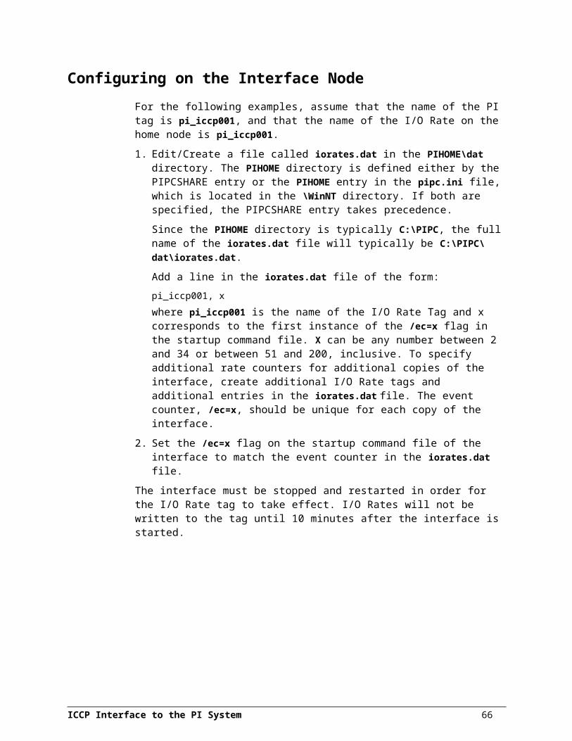
Interface Initialization ErrorsGot virtual machine initialization error <6603>
Generally, a <6603> error means that the INITIATE request was refused, implying that the request contained improper parameters. Check to make sure that the bilateral table parameters match between the ICCP server and PI-ICCP interface.Got virtual machine initialization error <6604>
A <6604> error means that the INITIATE request was not responded to at all (i.e. that there is no receiving OSI stack or ICCP server to respond to the call. Check to ensure that the ICCP server application and the OSI Stack on the remote node and that they are configured to recognize requests from the OSI Stack and PI-ICCP application. Use the “osiping <ARName>” utility to test stack connectivity.
MMS PDU Rejection ErrorsIf any of the requests ICCP (e.g. INTIATE, DELETE, CREATE, …) fail for a syntax problem dealing with the underlying MMS layer this message should appear:
Got a PDU rejection code from <local|remote>: PDU ID <#>, ISO Class <#>, Code <#>
A PDU rejection is a fairly serious error that implies a certain level of incompatibility between MMS-level messages sent between applications. The level of the message is either “local” (PI-ICCP Interface or OSI stack on the Interface node) or “remote” (ICCP Server or OSI stack on the server side). The PDU ID corresponds to the same ID used to track packets in the PDU log (enabled via the /pdu switch). Common PDU Reject codes are as follows:
REJECT CLASS = 1 CONFIRMED REQUEST PDU PROBLEM
Code
Description
0 OTHER Returned due to a reason other than any of those identified for this Reject PDU type
1 UNRECOGNIZED-SERVICE Used when service requested is not supported or recognized.
2 UNRECOGNIZED-MODIFIER Used when modifier requested is not supported or recognized.
3 INVALID-INVOKE-ID Used when an Invoke ID does not meet ISO 9506 requirements.
4 INVALID-ARGUMENT Used when services argument does not meet ISO 9506 requirements.
5 INVALID-MODIFIER Used when service modifier does not meet ISO 9506 requirements.
6 MAXIMUM-SERVICES-OUTSTANDING-EXCEEDED
Used when negotiated maximum number of outstanding confirmed services is exceeded by a confirmed service request.
ICCP Interface to the PI System 68
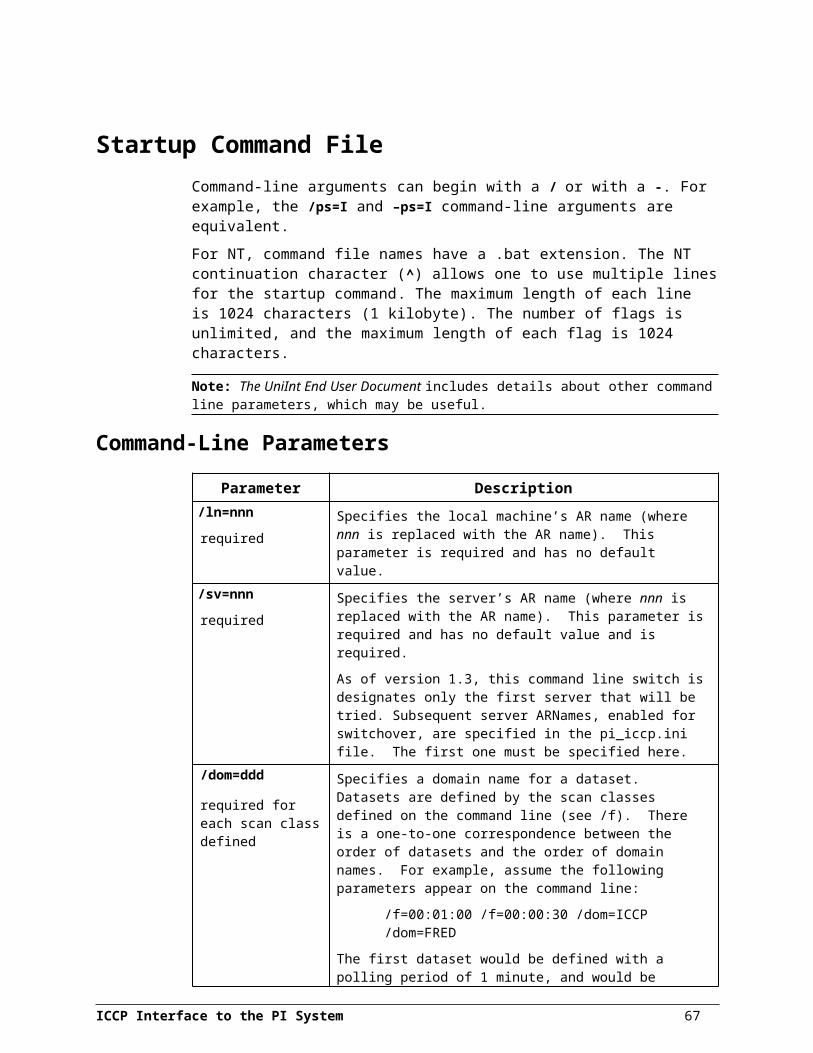
Code
Description
7 MAXIMUM-SEGMENT-LENGTH-EXCEEDED (DIS only)
Reserved for further definition per IS specification.
8 MAXIMUM-RECURSION-EXCEEDED
Used when received PDU exceeds maximum data structure nesting level
9 VALUE-OUT-OF-RANGE Used when received PDU contains one or more parameters whose values exceed the range allowed by ISO 9506.
DataSet and TransferSet Instantiation ErrorsListed below are some of the common error classes and their corresponding codes.
ERROR CLASS = 0 VMD STATE PROBLEMSThis error class is returned whenever the state of the VMD is such that the requested service may not be executed.
Code
Description
0 OTHER Returned due to a reason other than any of those identified for this error class
1 VMD-STATE-CONFLICT
Returned when a request is made that alters the VMD in a way that conflicts with the current state.
2 VMD-OPERATIONAL-PROBLEM
Returned when a request is made that may not be honored due to VMD operational problems.
3 DOMAIN-TRANSFER-PROBLEM
Returned when a transmitted Load Data contains an inconsistency. This may prevent it from being used.
4 STATE-MACHINE-ID-INVALID
Returned when there is no state machine associated with the state machine ID.
ERROR CLASS = 1 APPLICATION REFERENCE PROBLEMSThis error class is returned with respect to associations other than those established between a MMS client and a MMS server.
Code
Description
0 OTHER Returned due to a reason other than any of those identified for this error class
1 APPLICATION-UNREACHABLE
Returned when reference application is unreachable.
2 CONNECTION-LOST Returned when connection to specific application is lost before service was finished.
3 APPLICATION-REFERENCE-INVALID
Returned due to invalid application reference.
4 CONTEXT-UNSUPPORTED
Returned when referenced application does not support indicated application context.
ICCP Interface to the PI System 69

Appendix A: Error and Informational Messages
ERROR CLASS = 2 DEFINITION PROBLEMSThis error class is returned when there are problems with Object definitions.
Code
Description
0 OTHER Returned due to a reason other than any of those identified for this error class
1 OBJECT-UNDEFINED Returned when object with stated name does not exist.
2 INVALID-ADDRESS Returned when specified address is invalid because format is incorrect or out of range.
Applies only to unnamed variable objects, and only when parameter VADR is chosen.
3 TYPE-UNSUPPORTED Returned when unsupported or inappropriate type is specified.
4 TYPE-INCONSISTENT Returned when specified type is inconsistent with service or referenced object.
5 OBJECT-EXISTS Returned when defined object already exists.
6 OBJECT-ATTRIBUTE-INCONSISTENT
Returned when specified object has inconsistent attributes.
ERROR CLASS = 4 SERVICE PROBLEMSThis error class is returned whenever there are problems with the service primitives.
Code
Description
0 OTHER Returned due to a reason other than any of those identified for this error class.
1 PRIMITIVES-OUT-OF-SEQUENCE
Returned when service primitive sequence is invalid.
2 OBJECT-STATE-CONFLICT
Returned when current object state does not permit a response for the specified service request..
3 PDU-SIZE (DIS only) This value is reserved for future definition in IS specification.
4 CONTINUATION-INVALID
Returned when file name to continue after is not a member of the group of files included in the file specification.
5 OBJECT-CONSTRAINT-CONFLICT
Returned when current constraints on an object prevent execution of a service request.
Note that this error class has been returned when the maximum number of objects in a dataset has been exceeded. In this case, recommended workaround is to reduce the number of objects per dataset using the /mdo=# switch. For example, if the number calculated by the interface is set to 244 objects per dataset and “Class<4> Code<0>” PDU rejection errors are being received. Stop the interface, add (or edit) the /mdo switch to /mdo=240, and restart the interface.
70
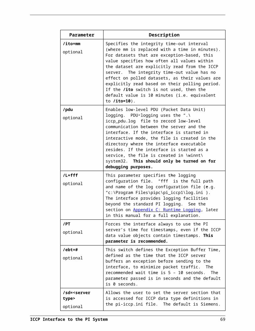
ERROR CLASS = 7 ACCESS PROBLEMSThis error class is returned whenever the requested service to an object was incorrectly specified.
Code
Description
0 OTHER Returned due to a reason other than any of those identified for this error class
1 OBJECT-ACCESS-UNSUPPORTED
Returned when object is not defined for requested access.
2 OBJECT-NON-EXISTENT
Returned for non-existent object.
3 OBJECT-ACCESS-DENIED
Returned when MMS client has insufficient privilege to request the operation.
4 OBJECT-INVALIDATED
Returned when attempted access references defined object that has undefined reference attribute.
In all cases, ICCP supports only the transportation of a reject or error class and code. As such, the context of the call must be determined separately (usually from within the application that gives rise to the error). This context is given by establishing the PDU ID and the corresponding operation involved with that PDU. More verbose packet oriented messaging is obtained by activating the PDU log (i.e. using the /pdu switch) in the interface.
Often diagnosing the source of a PI-ICCP error requires the coordination of a number of logs:
1) On the PI-ICCP interface side:a. Pipc.logb. Pi_iccp#.log (application log)c. Osilld.log (OSI Stack log)d. Iccp_pdu.log (MMS PDU packet log)
2) On the ICCP server side:a. Application logb. OSI Stack log
All of the logs should contain the same timeframe in order to determine the sequence of events, which preceded the error. Armed with this information, in addition to the specific error code and class, one can often target the application that is the source of the error and work from there to rectify the situation.
Note that an error code of 0 in all classes is a generic catchall for unknown error. The user should refer to the MMS standard in the ISO 9506 protocol for more detail on exact error codes and their meanings.
ICCP Interface to the PI System 71

Appendix A: Error and Informational Messages
System Errors and PI ErrorsSystem errors are associated with positive error numbers. Errors related to PI are associated with negative error numbers.
Error Descriptions On NT, descriptions of system and PI errors can be obtained with the pidiag utility:\PI\adm\pidiag –e error_number
72

Appendix B:ICCP and MMS Overview
ICCP, or Inter-control Center Communications Protocol, is a protocol standard, defined by ISO, primarily for use in communication between utility companies. This standard is built on top of an existing protocol standard; MMS (Manufacturing Message Specification). In this relationship, MMS provides the data type, data transfer, and connection specifications, while ICCP uses the MMS data types to create custom types for use with power utilities.
MMS, using ICCP data types, is an extremely complex protocol that provides a vast number of services. Although ICCP is designed primarily for transfer of utility data, it is suitable for transfer of any real-time process or archived data.
ICCP is a companion standard to MMS, meaning that ICCP extends the functionality of the MMS protocol in a definable and acceptable way. ICCP uses the transport mechanisms provided by MMS to perform data transfers.
This section describes the aspects of MMS and ICCP that are important to the operation of the interface.
ICCP CommunicationBoth ICCP and MMS are based on the OSI 7-layer network model, and reside in layer 7, the API layer. Therefore, the underlying physical network topology is of no concern to ICCP applications.
MMS is implemented as a client-server protocol. During normal communication, the client (interface) initiates communication with the server, and the server responds appropriately. However, the server may, under certain circumstances (such as data events), send unsolicited data to the client.
Messages initiated by the server are called reports, while messages initiated by the client are called requests. If the /pdu switch is used in the interface startup file, the iccp_pdu.log file will show reports as “MMS INDICATION RECEIVED” and requests as “ISSUING MMS REQUEST”, and these should be followed by appropriate responses.
MMS ChannelsThe interface uses a single MMS communication channel (see MMS documentation for more information on communications channels).
Functional BlocksThe ICCP protocol logically separates its services into nine distinct blocks as described below:
1. Basic services for transfer of process data.
2. Process data exception reporting.
3. Binary (BLOB) data transfers.
4. Simple file transfer.ICCP Interface to the PI System 73

5. Device control, including device setpoints and control outputs.
6. API services for starting and stopping remote applications.
7. System status event reporting.
8. Accounting information, such as power consumption.
9. Time series data, including trends and archived data.
Of the nine blocks, only block one needs to implemented for ICCP compliance. This block allows simple scan-based retrieval of process data, and the ability to write values to remote points. For many applications, this is all the functionality required. However, for the PI-ICCP interface, the ability to receive exception-based data is required, so block 2, exception reporting, is also implemented. Only blocks 1 and 2 are available via the PI-ICCP interface.
Object TypesMMS is extremely flexible in the data types that it supports. Several foundation data types are defined, such as int32 and real, which can be grouped together to form complex data structures. These data structures can be created dynamically (at runtime) using a textual descriptor. Both the MMS client and server must be able to parse the descriptor and create local (application dependant) representations of the structures for data storage.
ICCP TypesThe majority of the ICCP standard is devoted to defining the data types, called objects, based on the MMS foundation types. The standard also defines how the data objects are to be used, i.e., the various required property values and responses. The interface uses three main object types:
Data Value Object; Data Set Object; and Data Set Transfer Set Object.
The data value object contains properties (structure fields), which facilitate the retrieval and changing of data values. Each data value object is associated with a process tag. The data set object is roughly analogous to a scan class in PI, where tags (data value objects) can be logically grouped.
In the context of the PI-ICCP interface, the Transfer Set object allows a client to register with a server for exception-based updated (unsolicited reports).
All ICCP objects are objects in the standard programming sense, in that they have certain methods associated with them. Each object may contain methods from either, or both, of the method types defined in ICCP: operations and actions. Operations are invoked as a result of a client request, while actions result in a report being generated by the server.
Bilateral TablesIn order for an ICCP client to connect to an ICCP server, the server must grant the client permission to do so. The permission settings for client are maintained within a Bilateral Table. The attributes for the bilateral table are defined within the ICCP standard, but the implementation is not defined, i.e., database table, flat file, etc.
The server must have a Bilateral Table defined for each client that wishes to connect. The Bilateral Table includes lists of all data objects that the client is able to access. The
ICCP Interface to the PI System 74

interface accesses the Bilateral Table as defined by the ICCP specification, but ignores the returned values.
The interface now allows for option of returning values for the bilateral table if the ICCP server requests such information. For more info see the section entitled, PI_ICCP.ini File: Bilateral Table Information.
MMS-EASE ToolkitThe development of the MMS portion of the interface relies on the use of the MMS-EASE development toolkit supplied by SISCO (Systems Integration Specialists Company). This toolkit provides its’ own protocol stack and run-time library, which are used by the interface executable. MMS-EASE must be installed prior to the interface installation.
Protocol StackBy default, MMS-EASE is configured to use its own protocol stack when installed. However, MMS-EASE may also be configured to use tcp/ip. This choice will be left up to the interface user, based on recommendations from SISCO or personal preference.
ICCP Interface to the PI System 75
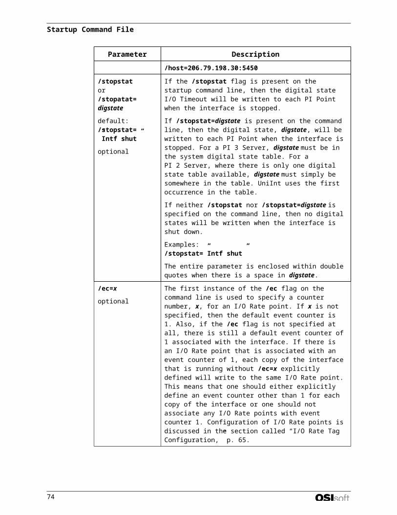
Appendix C:Runtime Logging
The PI-ICCP interface provides extensive run-time operation logging facilities. The logging facility provides the following capabilities:
multiple detail levels: low, medium, high, none, all; a forced writes option that, when enabled, commits all data to the drive after
each write (note: slows the process significantly and log file will not “wrap”); a screen logging option that will echo the log entries to the console; ability to append or overwrite existing log; circular log file format with selectable size; and a common log file viewer for Windows95 and Windows NT.
These options can be set or selected using a logging configuration file. The configuration file is a text file with a “loose” format; only lines beginning with a minus sign (-) are treated as parameters, and all parameters are case-insensitive. Any parameters not included in the file will be set to the default values. The following parameters are supported:
-F = forced writes, either TRUE or FALSE, default=FALSE
-D = detail level, 0 to 9 (see table later in this annex) default=LOG_MEDIUM
-L = logfile name, required (no default)
-M = max logfile size, in bytes, default=50000
-N = start new file, either TRUE or FALSE, default=TRUE
-S = enable screen logging, either TRUE or FALSE, default=TRUE
There are no limits on the size or filename of the configuration file. The file should be named and placed as specified within the /L=”drive:\path\filename” switch. A sample configuration file is shown below.
** Set log level to LOG_MEDIUM-D2** Set log filename-Lc:\temp\test.log** Enable screen logging-Strue** Set max logfile size to 10K-M10240
Run Time Logging ConfigurationThe user has the ability to change the operation of the logging facilities at runtime by creating several Logging Tags. The logging tags provide a mechanism for changing the logging configuration during run-time. When the logging configuration needs to be changed, a value can be written to the appropriate tag. For each possible logging configuration change, there is a specific PI tag. The following table describes the configuration changes that are permitted and the associated tags and values:
ICCP Interface to the PI System 77

Configuration Parameter
Tagname Appropriate Values
Detail level L$LOG_LEVEL 9 = Everything (very high detail)
8 = No logs, except critical errors
3 = High detail
2 = Medium detail
1 = Low detail
Log to screen L$LOG_SCREEN 0 = off, 1 = log to screen
Enable forced writes L$LOG_FORCED 0 = off, 1 = writes committed immediately
All logging tags must be configured as output tags of type Integer, and the ShutDown attribute of the tag must be zero.
PDU LoggingThe PI-ICCP interface also provides the ability to log the low level MMS requests and responses generated by the interface and server. This option may be useful for debugging the server or interface configuration, but should not be used during normal operation.
Enable PDU (Packet Data Unit) logging by using the /pdu command line parameter. The PDU log file will be maintained in the iccp_pdu.log file, located in the interface’s home directory if the interface is run interactively. If the interface is started as a service, the file will be created in the default services directory, which is %systemroot%\system32. This file is viewable with any text editor (it cannot be viewed with the log viewer).
ICCP Interface to the PI System 78
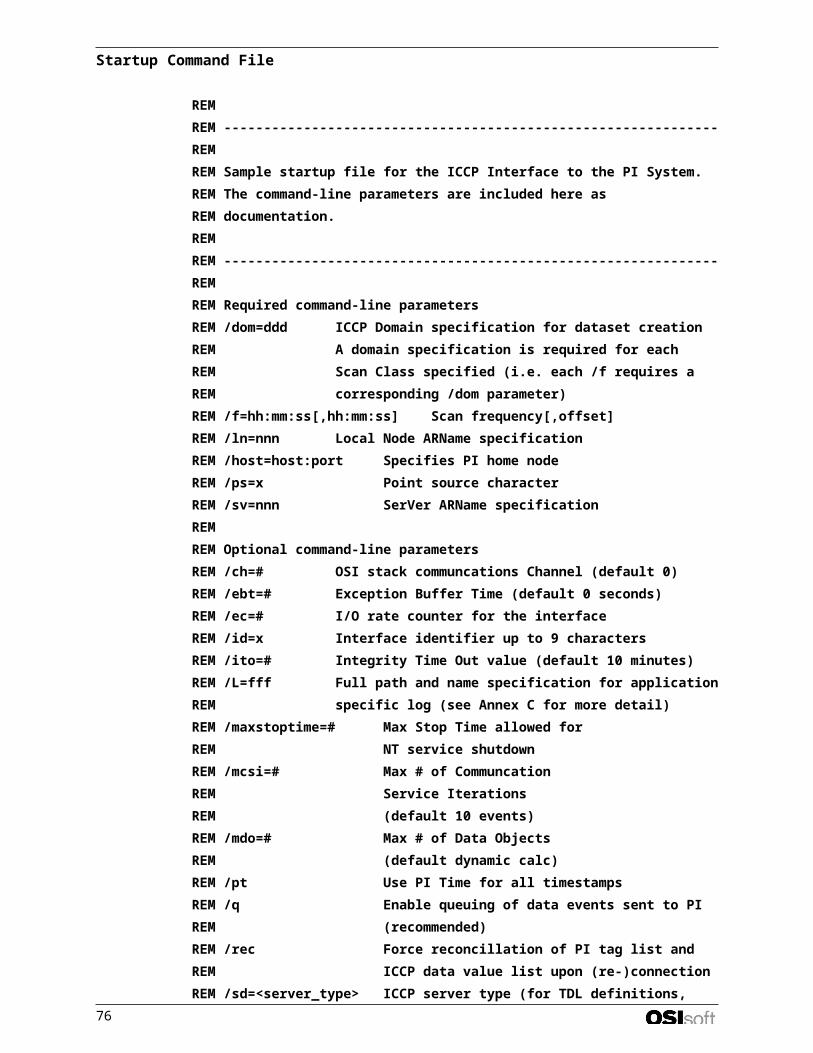
Appendix D:Server Compliance
The PI-ICCP interface has been tested with the following servers:
Server Version Platform Known Compliance AnomaliesSiemens 1.0 AIX Fully compliant
ABB/Spider 1.2 Dec Unix Fully compliant
GE-Harris XA21 1.3 AIX Fully Compliant
ABB/EMSYS 1.2 Dec Unix Fully Compliant
ICCP Interface to the PI System 79

Revision HistoryDate Author Comments
09-Apr-98 MH First draft
12-Mar-99 DCO Version 1.2
01-Jun-99 DCO Version 1.3
18-Jun-99 DCO Version 1.4
09-Jul-99 DCO Version 1.5
24-Sep-99 DCO Version 1.6
02-Nov-99 DCO & PK Version 1.7
29-Nov-00 DCO Version 1.8
23-May-01 DCO Version 1.8.1 – Added /maxstoptime=# option documentation. Also clarified documentation pertaining to “Switchover Server” definitions in the pi_iccp.ini.
23-Apr-02 DCO Updated Manual to use Version 1.10 of the OSI interface manual skeleton. Version 1.8.5 of the interface.
16-Apr-03 DCO Added MMS PDU rejection code class 4 to Appendix A: Error codes. Updated interface references to current version (1.8.7). Added verbiage for clarification in SwitchOver Servers section of PI_ICCP.ini file discussion.
27-May-03 DCO Added the command line switch documentation for /nsq (“No State Quality”). Version 1.8.10.0 of the interface (interface standard altered to use 4 number release code).
27-Jun-03 DCO Improved verbiage in “Source of Timestamp” section of the manual, making it explicit that the interface uses either the timestamp included with the ICCP data value or (if not present or the /PT is being used) the PI server time (as calculated from the offset between the PI server and local node).
23-Aug-03 CG Fixed headers & footers
ICCP Interface to the PI System 81


