56

Ice Protection SystemDA 42 AFM
Supplement S03
Page 9-S03-2 21-Jan-2009 Rev. 2 Doc. # 7.01.05-E
Intentionally left blank.
DA 42 AFM
Supplement S03Ice Protection System
Doc. # 7.01.05-E Rev. 3› 27-May-2015› Page 9-S03-3
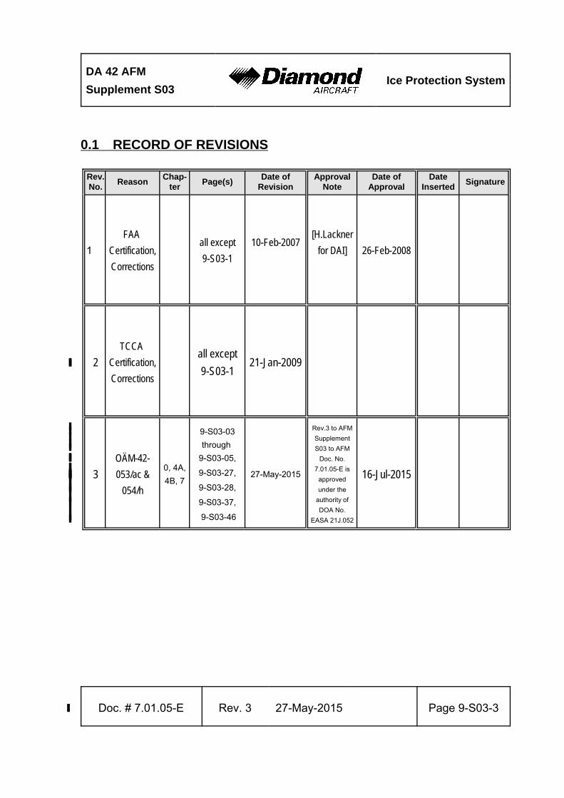
0.1 RECORD OF REVISIONS
Rev.No.
ReasonChap-
terPage(s)
Date ofRevision
ApprovalNote
Date ofApproval
DateInserted
Signature
1
FAA
Certification,
Corrections
all except
9-S03-1
10-Feb-2007[H.Lackner
for DAI] 26-Feb-2008
2
TCCA
Certification,
Corrections
all except
9-S03-121-Jan-2009››››
3›
OÄM-42-›
053/ac &›
054/h›
0, 4A,›4B, 7›
9-S03-03›through ›
9-S03-05,›
9-S03-27,›
9-S03-28,›
9-S03-37,›
9-S03-46›
27-May-2015›
Rev.3 to AFM›Supplement›S03 to AFM›
Doc. No.›7.01.05-E is›
approved›under the›
authority of›DOA No.›
EASA 21J.052›
16-Jul-2015›››
Ice Protection SystemDA 42 AFM
Supplement S03
Page 9-S03-4 27-May-2015› Rev. 3› Doc. # 7.01.05-E
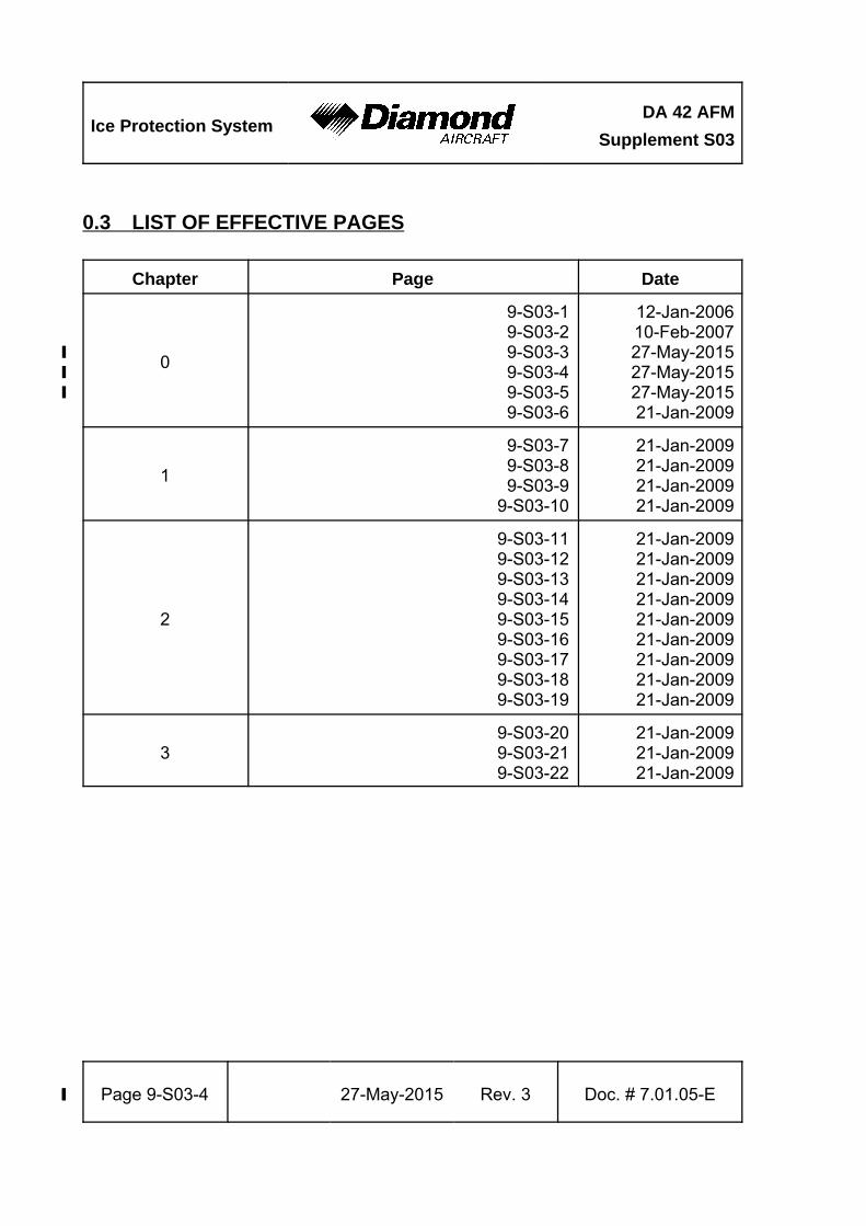
0.3 LIST OF EFFECTIVE PAGES
Chapter Page Date
0
9-S03-19-S03-29-S03-39-S03-49-S03-59-S03-6
12-Jan-200610-Feb-200727-May-2015›27-May-2015›27-May-2015›21-Jan-2009
1
9-S03-79-S03-89-S03-9
9-S03-10
21-Jan-200921-Jan-200921-Jan-200921-Jan-2009
2
9-S03-119-S03-129-S03-139-S03-149-S03-159-S03-169-S03-179-S03-189-S03-19
21-Jan-200921-Jan-200921-Jan-200921-Jan-200921-Jan-200921-Jan-200921-Jan-200921-Jan-200921-Jan-2009
39-S03-209-S03-219-S03-22
21-Jan-200921-Jan-200921-Jan-2009
DA 42 AFM
Supplement S03Ice Protection System
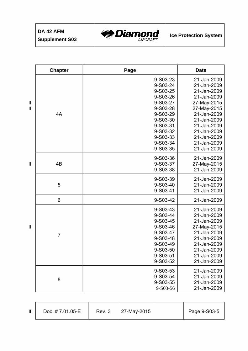
Chapter Page Date
Doc. # 7.01.05-E Rev. 3› 27-May-2015› Page 9-S03-5
4A
9-S03-239-S03-249-S03-259-S03-269-S03-279-S03-289-S03-299-S03-309-S03-319-S03-329-S03-339-S03-349-S03-35
21-Jan-200921-Jan-200921-Jan-200921-Jan-2009
27-May-2015›27-May-2015›21-Jan-200921-Jan-200921-Jan-200921-Jan-200921-Jan-200921-Jan-200921-Jan-2009
4B9-S03-369-S03-379-S03-38
21-Jan-200927-May-2015›21-Jan-2009
59-S03-399-S03-409-S03-41
21-Jan-200921-Jan-200921-Jan-2009
6 9-S03-42 21-Jan-2009
7
9-S03-439-S03-449-S03-459-S03-469-S03-479-S03-489-S03-499-S03-509-S03-519-S03-52
21-Jan-200921-Jan-200921-Jan-2009
27-May-2015›21-Jan-200921-Jan-200921-Jan-200921-Jan-200921-Jan-200921-Jan-2009
8
9-S03-539-S03-549-S03-559-S03-56
21-Jan-200921-Jan-200921-Jan-200921-Jan-2009
Ice Protection SystemDA 42 AFM
Supplement S03
Page 9-S03-6 21-Jan-2009 Rev. 2 Doc. # 7.01.05-E
0.4 TABLE OF CONTENTS
Page
1. GENERAL . . . . . . . . . . . . . . . . . . . . . . . . . . . . . . . . . . . . . . . . . . . . . . . . . 9-S03-7
2. OPERATING LIMITATIONS . . . . . . . . . . . . . . . . . . . . . . . . . . . . . . . . . . 9-S03-11
3. EMERGENCY PROCEDURES . . . . . . . . . . . . . . . . . . . . . . . . . . . . . . . . 9-S03-20
4A. NORMAL OPERATING PROCEDURES . . . . . . . . . . . . . . . . . . . . . . 9-S03-23
4B. ABNORMAL OPERATING PROCEDURES . . . . . . . . . . . . . . . . . . . . 9-S03-36
5. PERFORMANCE . . . . . . . . . . . . . . . . . . . . . . . . . . . . . . . . . . . . . . . . . . . 9-S03-39
6. MASS AND BALANCE . . . . . . . . . . . . . . . . . . . . . . . . . . . . . . . . . . . . . . 9-S03-42
7. DESCRIPTION OF THE AIRPLANE AND ITS SYSTEMS . . . . . . . . . . . 9-S03-43
8. AIRPLANE HANDLING, CARE AND MAINTENANCE . . . . . . . . . . . . . . 9-S03-53
DA 42 AFM
Supplement S03Ice Protection System
Doc. # 7.01.05-E Rev. 2 21-Jan-2009 Page 9-S03-7
1. GENERAL
1.1 INTRODUCTION
This Supplement to the Airplane Flight Manual contains all necessary information to
operate the ice protection system of the DA 42 in known icing conditions.
The DA 42 can be equipped with an optional ice protection system in accordance with
the Optional Design Change Advisory OÄM 42-054. It distributes a thin film of de-icing
fluid on the wings, vertical stabilizer, horizontal stabilizer, propellers and canopy. This
prevents the formation and accumulation of ice.
NOTE
The ice protection system is not a "de-icing" system in the
usual sense. It can remove only small accumulations of ice.
Its main purpose is to prevent the accretion of ice.
Ice Protection SystemDA 42 AFM
Supplement S03
Page 9-S03-8 21- Jan-2009 Rev. 2 Doc. # 7.01.05-E
WARNING
Known icing conditions are defined by CS 25 / FAR Part 25,
Appendix C. These conditions do not include, nor were tests
conducted in, all icing conditions that may be encountered
(e.g., freezing rain, freezing drizzle, mixed phase icing con-
ditions or conditions defined as severe). Flight in these
conditions must be avoided. Some icing conditions not
defined in CS 25 / FAR part 25 have the potential of producing
hazardous ice accumulations, which (1) exceed the
capabilities of the airplane's ice protections equipment, and/or
(2) create unacceptable airplane performance. Inadvertent
operation in these conditions may be detected by heavy ice
accumulation on the windshield, or when ice forms on the side
areas of the canopy. Another indication are the rapid
formation and shedding of bars of ice (6 mm or 1/4 inch
thickness or larger) from the porous panels. If these
conditions are encountered, the pilot should take immediate
action to select HIGH/MAX flow rate and leave these
conditions by changing altitude or turning back or even
continuing on the same course if clear air is known to be
immediately ahead.
DA 42 AFM
Supplement S03Ice Protection System
Doc. # 7.01.05-E Rev. 2 21-Jan-2009 Page 9-S03-9
1.5 DEFINITIONS AND ABBREVIATIONS
(b) Meteorological Terms
De-Ice or De-Icing: The periodic shedding or removal of ice accumulations from a
surface, by destroying the bond between the ice and the protection
surface.
Freezing Drizzle: Drizzle is precipitation on the ground or aloft in the form of liquid
water drops that have diameters less than 0.5 mm and greater than
0.05 mm (50 μm to 500 μm, 0.002 to 0.02 in). Freezing drizzle is
drizzle that exists at air temperatures less than 0 °C or 32 °F
(supercooled water), remains in liquid form, and freezes upon
contact with objects on the surface or airborne.
Freezing Rain: Rain is precipitation on the ground or aloft in the form of liquid
water drops which have diameters greater than 0.5 mm (0.02 in).
Freezing rain is rain that exists at air temperatures less than zero
degrees C (supercooled water), remains in liquid form, and freezes
upon contact with objects on the surface or airborne.
Ice Crystals: Any one of a number of macroscopic, crystalline forms in which
ice appears. Examples are hail and snow.
Icing Conditions: An icing condition is defined as visually detected ice, or the
presence of visible moisture in any form at an indicated outside
air temperature (OAT) of +3 °C (37.4 °F) or below.
LWC: Liquid water content. The total mass of water contained in liquid
drops within a unit volume or mass of air.
Ice Protection SystemDA 42 AFM
Supplement S03
Page 9-S03-10 21- Jan-2009 Rev. 2 Doc. # 7.01.05-E
Mixed Phase Icing Conditions:
A homogeneous mixture of supercooled water drops and ice
crystals existing within the same cloud environment.
Supercooled Water: Liquid water at a temperature below the freezing point of 0 °C
(32 °F).
(c) Flight Performance and Flight Planning
Continuous Operation:
Typical continuous operations in icing conditions are holding and
cruise.
(i) Miscellaneous
CS 25 / FAR Part 25, Appendix C:
Certification icing condition standard for approving ice protection
provisions on airplanes. The conditions are specified in terms of
altitude, temperature, LWC, representative droplet size, and cloud
horizontal extent.
ICTS: Ice contaminated tailplane stall.
Protected Surface: A surface containing ice protection, typically located at the
surface’s leading edge.
Residual Ice: Ice that remains on a protected surface immediately following the
actuation of a deicing system.

DA 42 AFM
Supplement S03Ice Protection System
Doc. # 7.01.05-E Rev. 2 21-Jan-2009 Page 9-S03-11
2. OPERATING LIMITATIONS
2.1 INTRODUCTION
2.1.1 METEOROLOGICAL CONDITIONS
Flight in meteorological conditions described as freezing rain or freezing drizzle, as
determined by the following visual cues, is prohibited:
(1) Unusually extensive ice accreted on the airframe in areas not normally observed
to collect ice.
(2) Accumulation of ice on the upper surface of the wing aft of the protected area.
(3) Accumulation of ice on the propeller spinner further back than normally observed.
If the airplane encounters conditions that are determined to contain freezing rain or freezing
drizzle, the pilot must immediately exit the freezing rain or freezing drizzle conditions by
changing altitude or turning back or even continuing on the same course if clear air is
known to be immediately ahead.
NOTE
The prohibition on flight in freezing rain or freezing drizzle is
not intended to prohibit purely inadvertent encounters with
the specified meteorological conditions; however, pilots
should make all reasonable efforts to avoid such encounters
and must immediately exit the conditions if they are
encountered.
Ice Protection SystemDA 42 AFM
Supplement S03
Page 9-S03-12 21- Jan-2009 Rev. 2 Doc. # 7.01.05-E
2.1.2 USE OF THE AUTOPILOT
Use of the autopilot is prohibited when any ice is observed forming aft of the protected
surfaces of the wing, or when unusual lateral trim requirements or autopilot trim warnings
are encountered.
NOTE
The autopilot may mask tactile cues that indicate adverse
changes in handling characteristics; therefore, the pilot should
consider not using the autopilot when any ice is visible on the
airplane.
DA 42 AFM
Supplement S03Ice Protection System
Doc. # 7.01.05-E Rev. 2 21-Jan-2009 Page 9-S03-13
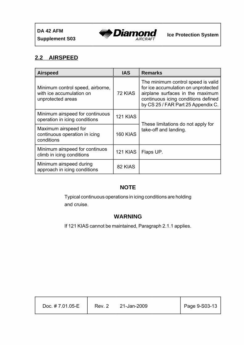
2.2 AIRSPEED
Airspeed IAS Remarks
Minimum control speed, airborne,with ice accumulation onunprotected areas
72 KIAS
The minimum control speed is validfor ice accumulation on unprotectedairplane surfaces in the maximumcontinuous icing conditions definedby CS 25 / FAR Part 25 Appendix C.
Minimum airspeed for continuousoperation in icing conditions
121 KIAS
These limitations do not apply fortake-off and landing.Maximum airspeed for
continuous operation in icingconditions
160 KIAS
Minimum airspeed for continuosclimb in icing conditions
121 KIAS Flaps UP.
Minimum airspeed duringapproach in icing conditions
82 KIAS
NOTE
Typical continuous operations in icing conditions are holding
and cruise.
WARNING
If 121 KIAS cannot be maintained, Paragraph 2.1.1 applies.
Ice Protection SystemDA 42 AFM
Supplement S03
Page 9-S03-14 21- Jan-2009 Rev. 2 Doc. # 7.01.05-E
2.6 WARNING, CAUTION AND ADVISORY ALERTS
2.6.1 WARNING, CAUTION AND ADVISORY ALERTS ON THE G1000
NOTE
The alerts described in the following are displayed on the
Garmin G1000. Section 7.10 includes a detailed description
of the alerts.
The following table shows the color and significance of the warning, caution and advisory
alert lights on the G1000.
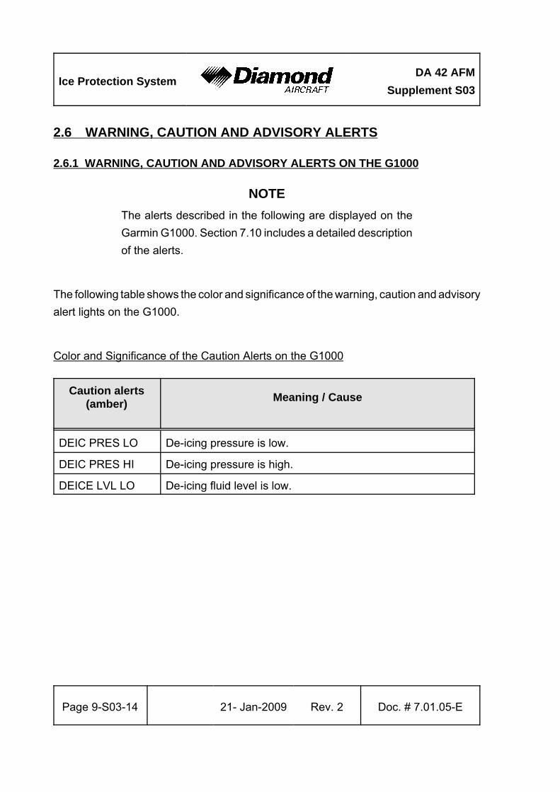
Color and Significance of the Caution Alerts on the G1000
Caution alerts(amber)
Meaning / Cause
DEIC PRES LO De-icing pressure is low.
DEIC PRES HI De-icing pressure is high.
DEICE LVL LO De-icing fluid level is low.
DA 42 AFM
Supplement S03Ice Protection System
Doc. # 7.01.05-E Rev. 2 21-Jan-2009 Page 9-S03-15
2.13 KINDS OF OPERATION
2.13.1 OPERATION IN ICING CONDITIONS
General
The DA 42 is approved for flight into known or forecast icing conditions as defined by
CS 25 / FAR Part 25, Appendix C "Continuous Maximum and Intermittent Icing Envelope"
only if the ice protection system is installed and serviceable.
Temperature Limitation
Minimum operation temperature for the Ice Protection System is -30°C (-22°F).
Take-off
Take-off with ice or snow accumulation or any frost on the airplane is prohibited.
NOTE
The airplane must be completely cleared of ice, snow and
similar accumulations. For approved de-icing fluids refer to
the main part of the AFM, Section 8.6 - DE-ICING.
Flight into Known or Forecast Icing Conditions
NOTE
The flaps and landing gear should only be extended and
retracted for take-off and landing
Ice Protection SystemDA 42 AFM
Supplement S03
Page 9-S03-16 21- Jan-2009 Rev. 2 Doc. # 7.01.05-E
NOTE
The flaps may not be set to the LDG position during flights
in icing conditions and/or with residual ice on protected or
unprotected surfaces.
NOTE
Intentional single-engine operation during flights under known
or forecast icing conditions is not permitted.
Minimum Operational Equipment (Serviceable)
Flight into known or forecast icing condition requires the following equipment to be installed
and serviceable:
* Ice Protection System installed in accordance with the Optional Design Advisory
OÄM 42-054.
NOTE
Both wing ice inspection lights must be operative prior to flight
into known or forecast icing conditions at night. This
supersedes any relief provided by the table given in the main
part of the AFM in Section 2.13.
DA 42 AFM
Supplement S03Ice Protection System
Doc. # 7.01.05-E Rev. 2 21-Jan-2009 Page 9-S03-17
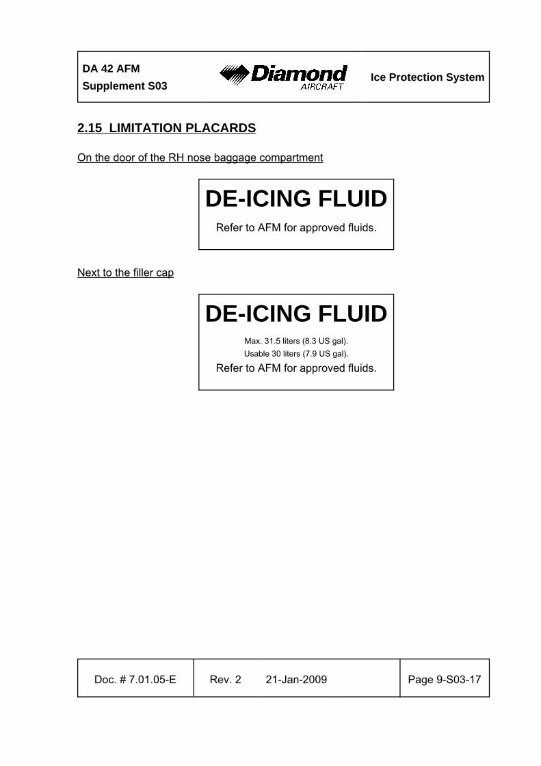
2.15 LIMITATION PLACARDS
On the door of the RH nose baggage compartment
DE-ICING FLUIDRefer to AFM for approved fluids.
Next to the filler cap
DE-ICING FLUIDMax. 31.5 liters (8.3 US gal).
Usable 30 liters (7.9 US gal).
Refer to AFM for approved fluids.
Ice Protection SystemDA 42 AFM
Supplement S03
Page 9-S03-18 21- Jan-2009 Rev. 2 Doc. # 7.01.05-E
2.17 DE-ICING FLUIDS FOR SYSTEM OPERATION
2.17.1 MINIMUM DE-ICING FLUID QUANTITY FOR DISPATCH
The minimum de-icing fluid quantity for dispatch is 22 liter (5.8 US gal). This amount
corresponds to an indication of 3/4 full on the G1000.
NOTE
This minimum allows at least 90 minutes of ice protection with
NORM selected. The pilot must ensure adequate fluid quantity
before each flight.
NOTE
The maximum usable tank capacity is 30 liter (7.9 US gal).
The maximum tank capacity is 31.5 liter (8.3 US gal).
Maximum system operating times with maximum usable
quantity of de-icing fluid:
NORM mode . . . . . . . . . . . . . . . . . . 2 hrs. 30 min.
HIGH mode . . . . . . . . . . . . . . . . . . . 1 hr.
MAX mode . . . . . . . . . . . . . . . . . . . 30 min.
DA 42 AFM
Supplement S03Ice Protection System
Doc. # 7.01.05-E Rev. 2 21-Jan-2009 Page 9-S03-19
2.17.2 DE-ICING FLUIDS
Approved de-icing fluids for use in the Ice Protection System are:
• AL-5 (DTD 406B)
• Aeroshell Compound 07
WARNING
The approved de-icing fluids are harmful. They are Glycol
based with different additives. Refer to the Material Safety
Data Sheets for proper handling which are available from the
supplier of the de-icing fluid.
CAUTION
The use of other fluids will provide a correspondingly lower
standard of ice protection or may cause damage to the ice
protection system.
Ice Protection SystemDA 42 AFM
Supplement S03
Page 9-S03-20 21- Jan-2009 Rev. 2 Doc. # 7.01.05-E
3. EMERGENCY PROCEDURES
3.4 G1000 FAILURES
3.4.6 ERRONEOUS OR LOSS OF DE-ICING FLUID DISPLAY
If the de-icing fluid quantity is known, the remaining system operating time can be
estimated based on the durations given in Section 2.17.2 - DE-ICING FLUIDS.
1. Icing conditions . . . . . . . . . . . . . . . . . . . . . . . leave the icing area as soon as
practicable
3.5 ONE ENGINE INOPERATIVE PROCEDURES
3.5.6 ENGINE FAILURES IN FLIGHT
1. Leave the icing area (by changing altitude or turning back or even continuing on
the same course if clear air is known to be immediately ahead).
2. DE-ICE . . . . . . . . . . . . . . . . . . . . . . . . . . . . . HIGH
3. Proceed in accordance with the procedure given in Section 3.5.6 - ENGINE
FAILURES IN FLIGHT in the main part of the AFM.
3.7 FAILURES IN THE ELECTRICAL SYSTEM
3.7.1 COMPLETE FAILURE OF THE ELECTRICAL SYSTEM
1. Leave the icing area (by changing altitude or turning back or even continuing on
the same course if clear air is known to be immediately ahead).
2. Proceed in accordance with the procedure given in Section 3.7.1 - COMPLETE
FAILURE OF THE ELECTRICAL SYSTEM in the main part of the AFM.
DA 42 AFM
Supplement S03Ice Protection System
Doc. # 7.01.05-E Rev. 2 21-Jan-2009 Page 9-S03-21
3.10 ICE PROTECTION SYSTEM EMERGENCIES
3.10.1 INADVERTENT ICING ENCOUNTER & EXCESSIVE ICE ACCUMULATION
1. DE-ICE . . . . . . . . . . . . . . . . . . . . . . . . . . . . . HIGH
2. MAX . . . . . . . . . . . . . . . . . . . . . . . . . . . . . . . press push button, to dissipate
ice build-up
NOTE
The MAX push button activates the maximum possible system
flow rate for 120 seconds.
3. Pitot heating . . . . . . . . . . . . . . . . . . . . . . . . . check ON
4. ICE LIGHT . . . . . . . . . . . . . . . . . . . . . . . . . . ON, as required
5. Cabin heat & defrost . . . . . . . . . . . . . . . . . . . ON
6. WINDSHIELD . . . . . . . . . . . . . . . . . . . . . . . . press push button, as required
If the system does not work properly:
Continue with Section 3.10.2 - FAILURE OF THE ICE PROTECTION SYSTEM.
If the system works properly, proceed as follows:
7. De-icing fluid level . . . . . . . . . . . . . . . . . . . . . check periodically
8. DE-ICE . . . . . . . . . . . . . . . . . . . . . . . . . . . . . NORM or HIGH, as
required. Monitor ice build-up
END OF CHECKLIST
Ice Protection SystemDA 42 AFM
Supplement S03
Page 9-S03-22 21- Jan-2009 Rev. 2 Doc. # 7.01.05-E
3.10.2 FAILURE OF THE ICE PROTECTION SYSTEM
A "failure" of the ice protection system is any condition in which the system fails to remove
ice from protected surfaces including the propellers and any system malfunction not
covered in the abnormal operating procedures given in Chapter 4B of this Supplement.
1. Leave the icing area (by changing altitude or turning back or even continuing on
the same course if clear air is known to be immediately ahead).
2. Maintain airspeed above 121 KIAS until final approach and landing.
3. FLAPS . . . . . . . . . . . . . . . . . . . . . . . . . . . . . . UP
4. Slip . . . . . . . . . . . . . . . . . . . . . . . . . . . . . . . . minimize
WARNING
With an inoperative ice protection system, set both POWER
levers to MAX and leave icing conditions as soon as possible.
In heavy icing conditions, it may not be possible to maintain
altitude or proper glide path on approach; in this case, it is
imperative that a safe airspeed be maintained, the stall
warning system may not function and there may be little or
no pre-stall buffet with heavy ice loads on the wing leading
edges.
5. Approach speed with residual ice . . . . . . . . . 91 KIAS
6. Increase landing distance from Section 5.3.11 by a factor of 1.4
END OF CHECKLIST
DA 42 AFM
Supplement S03Ice Protection System
Doc. # 7.01.05-E Rev. 2 21-Jan-2009 Page 9-S03-23
4A. NORMAL OPERATING PROCEDURES
CAUTION
Do not delay activation of the Ice Protection System if icing
conditions are encountered. For best operation, the system
should be activated prior to accumulation of ice on protected
surfaces.
WARNING
If ice is observed forming aft of the protected surfaces of the
wing, or if unusual lateral trim requirements or autopilot trim
warnings are encountered, accomplish the following:
* The flight crew should reduce the angle of attack by
increasing speed as much as the airplane configuration
and weather allow, without exceeding design maneuvering
speed.
* If the autopilot is engaged, hold the control stick firmly and
disengage the autopilot. Do not re-engage the autopilot
until the airframe is clear of ice.
* Leave the icing area immediately by changing altitude or
turning back or even continuing on the same course if clear
air is known to be immediately ahead; and
* Report these weather conditions to air traffic control.
Ice Protection SystemDA 42 AFM
Supplement S03
Page 9-S03-24 21- Jan-2009 Rev. 2 Doc. # 7.01.05-E
CAUTION
Flight in freezing rain, freezing drizzle, or mixed phase icing
conditions (supercooled water and ice crystals) may result
in hazardous ice build-up on protected surfaces exceeding
the capability of the ice protection system, or may result in
ice forming aft of the protected surfaces. This ice may not be
shed using the ice protection systems, and it may seriously
degrade the performance and controllability of the airplane.
Identification of Freezing Rain/Freezing Drizzle Icing Conditions
The following shall be used to identify freezing rain/freezing drizzle icing conditions:
(1) Unusually extensive ice accreted on the airframe in areas not normally observed
to collect ice.
(2) Accumulation of ice on the upper surface of the wing aft of the protected area.
(3) Accumulation of ice on the propeller spinner farther back than normally observed.
Identification of Possible Freezing Rain/Freezing Drizzle Conditions
The following may be used to identify possible freezing rain/freezing drizzle conditions:
(1 Visible rain at temperatures below +5 °C (41 °F) outside air temperature (OAT).
(2) Droplets that splash or splatter on impact at temperatures below +5 °C (41 °F) OAT.
(3) Performance losses larger than normally encountered in icing conditions. It is
possible to experience severe ice accretions not visible to the flight crew, such as
wing lower surface accretion or propeller blade accretion.
DA 42 AFM
Supplement S03Ice Protection System
Doc. # 7.01.05-E Rev. 2 21-Jan-2009 Page 9-S03-25
Procedures for Exiting the Freezing Rain/Freezing Drizzle Environment
These procedures are applicable to all flight phases from take-off to landing. Monitor the
outside air temperature. While ice may form in freezing drizzle or freezing rain at
temperatures as cold as -18 °C (0 °F), increased vigilance is warranted at temperatures
around freezing with visible moisture present. If the visual cues specified above for
identifying possible freezing rain or freezing drizzle conditions are observed, accomplish
the following:
(1) Exit the freezing rain or freezing drizzle icing conditions immediately to avoid
extended exposure to flight conditions outside of those for which the airplane has
been certificated for operation. Asking for priority to leave the area is fully justified
under these conditions.
(2) Avoid abrupt and excessive maneuvering that may exacerbate control difficulties.
(3) Do not engage the autopilot. The autopilot may mask unusual control system forces.
(4) If the autopilot is engaged, hold the control stick firmly and disengage the autopilot.
(5) If an unusual roll response or uncommanded control movement is observed, reduce
the angle of attack by increasing airspeed or rolling wings level (if in a turn), and
apply additional power, if needed.
(6) Avoid extending flaps during extended operation in icing conditions. Operation with
flaps extended can result in a reduced wing angle of attack, with ice forming on
the upper surface further aft on the wing than normal, possibly aft of the protected
area.
(7) If the flaps are extended, do not retract them until the airframe is clear of ice.
(8) Report these weather conditions to ATC.
Ice Protection SystemDA 42 AFM
Supplement S03
Page 9-S03-26 21- Jan-2009 Rev. 2 Doc. # 7.01.05-E
4A.6 CHECKLISTS FOR NORMAL OPERATING PROCEDURES
4A.6.1 PRE-FLIGHT INSPECTION
I. Cabin check
Ice Protection System
a) ELECT MASTER . . . . . . . . . . . . . . . . . . . . . . ON
b) DEICE FLUID . . . . . . . . . . . . . . . . . . . . . . . . check quantity
c) Canopy . . . . . . . . . . . . . . . . . . . . . . . . . . . . . closed
WARNING
De-icing fluids are harmful. Do not press the WINDSHIELD
push button when the canopy is open. Otherwise the de-icing
fluid may be sprayed into the cabin. For proper handling refer
to the Material Safety Data Sheets which are available from
the supplier of the de-icing fluid.
d) WINDSHIELD . . . . . . . . . . . . . . . . . . . . . . . . press push button
e) Spraybar . . . . . . . . . . . . . . . . . . . . . . . . . . . . evidence of de-icing fluid
NOTE
If the system has been inoperative for a while, has been
drained or has run dry, trapped air - suspected in the feeder
lines to the main pumps - can be removed from the feeder
lines to the main pumps by activating the windshield pumps
several times.
CONTINUED

DA 42 AFM
Supplement S03Ice Protection System
Doc. # 7.01.05-E Rev. 3› 27-May-2015› Page 9-S03-27
NOTE
Do not operate the main pumps with an empty de-icing fluid
tank. Operating the main system pumps with an empty de-
icing fluid tank can cause a future system malfunction. To re-
establish full system function special maintenance action is
required.
f) ANNUN-TEST . . . . . . . . . . . . . . . . . . . . . . . . ON
NOTE
The ANNUN-TEST mode activates the DEICE LVL LO
caution immediately if the de-ice fluid quantity is low and the
DEIC PRES LO caution after 120 seconds.
g) DEICE PRES HI . . . . . . . . . . . . . . . . . . . . . . verify NOT ILLUMINATED
h) DEICE LVL LO . . . . . . . . . . . . . . . . . . . . . . . check (must be annunciated if
de-icing fluid quantity is below
10 liter (2.6 US gal))
i) DEIC PRES LO . . . . . . . . . . . . . . . . . . . . . . . check, ILLUMINATED (refer to
NOTE)
j) ANNUN-TEST . . . . . . . . . . . . . . . . . . . . . . . . OFF›
k) PUMP 1 . . . . . . . . . . . . . . . . . . . . . . . . . . . . select›
l) DE-ICE . . . . . . . . . . . . . . . . . . . . . . . . . . . . . HIGH›
m) DEIC PRES LO . . . . . . . . . . . . . . . . . . . . . . . verify NOT ILLUMINATED›
CONTINUEDNOTE
Ice Protection SystemDA 42 AFM
Supplement S03
Page 9-S03-28 27-May-2015› Rev. 3› Doc. # 7.01.05-E
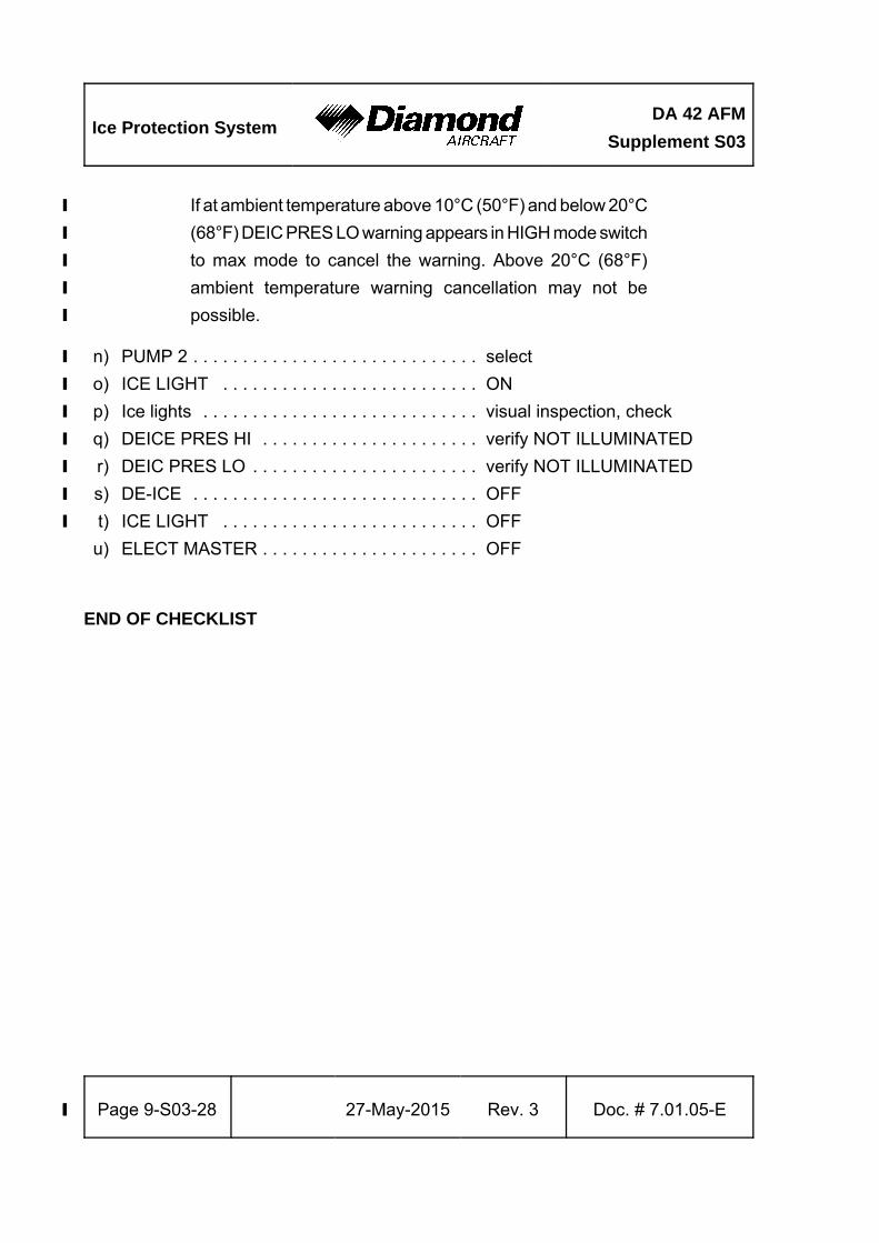
If at ambient temperature above 10°C (50°F) and below 20°C›
(68°F) DEIC PRES LO warning appears in HIGH mode switch›
to max mode to cancel the warning. Above 20°C (68°F)›
ambient temperature warning cancellation may not be›
possible.›
n) PUMP 2 . . . . . . . . . . . . . . . . . . . . . . . . . . . . . select›
o) ICE LIGHT . . . . . . . . . . . . . . . . . . . . . . . . . . ON›
p) Ice lights . . . . . . . . . . . . . . . . . . . . . . . . . . . . visual inspection, check›
q) DEICE PRES HI . . . . . . . . . . . . . . . . . . . . . . verify NOT ILLUMINATED›
r) DEIC PRES LO . . . . . . . . . . . . . . . . . . . . . . . verify NOT ILLUMINATED›
s) DE-ICE . . . . . . . . . . . . . . . . . . . . . . . . . . . . . OFF›
t) ICE LIGHT . . . . . . . . . . . . . . . . . . . . . . . . . . OFF›
u) ELECT MASTER . . . . . . . . . . . . . . . . . . . . . . OFF
END OF CHECKLIST
DA 42 AFM
Supplement S03Ice Protection System
Doc. # 7.01.05-E Rev. 2 21-Jan-2009 Page 9-S03-29
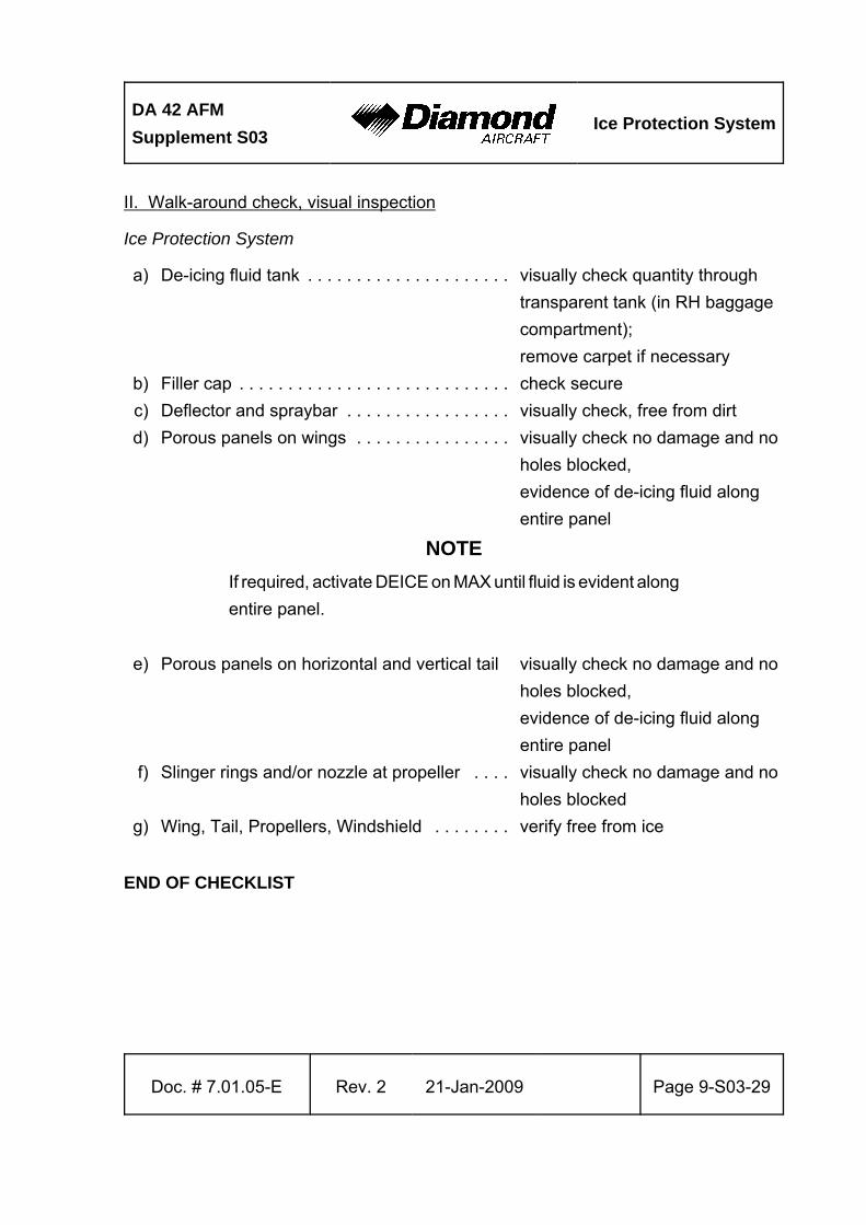
II. Walk-around check, visual inspection
Ice Protection System
a) De-icing fluid tank . . . . . . . . . . . . . . . . . . . . . visually check quantity through
transparent tank (in RH baggage
compartment);
remove carpet if necessary
b) Filler cap . . . . . . . . . . . . . . . . . . . . . . . . . . . . check secure
c) Deflector and spraybar . . . . . . . . . . . . . . . . . visually check, free from dirt
d) Porous panels on wings . . . . . . . . . . . . . . . . visually check no damage and no
holes blocked,
evidence of de-icing fluid along
entire panel
NOTE
If required, activate DEICE on MAX until fluid is evident along
entire panel.
e) Porous panels on horizontal and vertical tail visually check no damage and no
holes blocked,
evidence of de-icing fluid along
entire panel
f) Slinger rings and/or nozzle at propeller . . . . visually check no damage and no
holes blocked
g) Wing, Tail, Propellers, Windshield . . . . . . . . verify free from ice
END OF CHECKLIST
Ice Protection SystemDA 42 AFM
Supplement S03
Page 9-S03-30 21- Jan-2009 Rev. 2 Doc. # 7.01.05-E
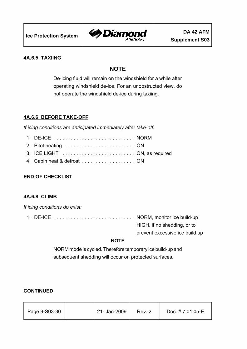
4A.6.5 TAXIING
NOTE
De-icing fluid will remain on the windshield for a while after
operating windshield de-ice. For an unobstructed view, do
not operate the windshield de-ice during taxiing.
4A.6.6 BEFORE TAKE-OFF
If icing conditions are anticipated immediately after take-off:
1. DE-ICE . . . . . . . . . . . . . . . . . . . . . . . . . . . . . NORM
2. Pitot heating . . . . . . . . . . . . . . . . . . . . . . . . . ON
3. ICE LIGHT . . . . . . . . . . . . . . . . . . . . . . . . . . ON, as required
4. Cabin heat & defrost . . . . . . . . . . . . . . . . . . . ON
END OF CHECKLIST
4A.6.8 CLIMB
If icing conditions do exist:
1. DE-ICE . . . . . . . . . . . . . . . . . . . . . . . . . . . . . NORM, monitor ice build-up
HIGH, if no shedding, or to
prevent excessive ice build up
NOTE
NORM mode is cycled. Therefore temporary ice build-up and
subsequent shedding will occur on protected surfaces.
CONTINUED
DA 42 AFM
Supplement S03Ice Protection System
Doc. # 7.01.05-E Rev. 2 21-Jan-2009 Page 9-S03-31
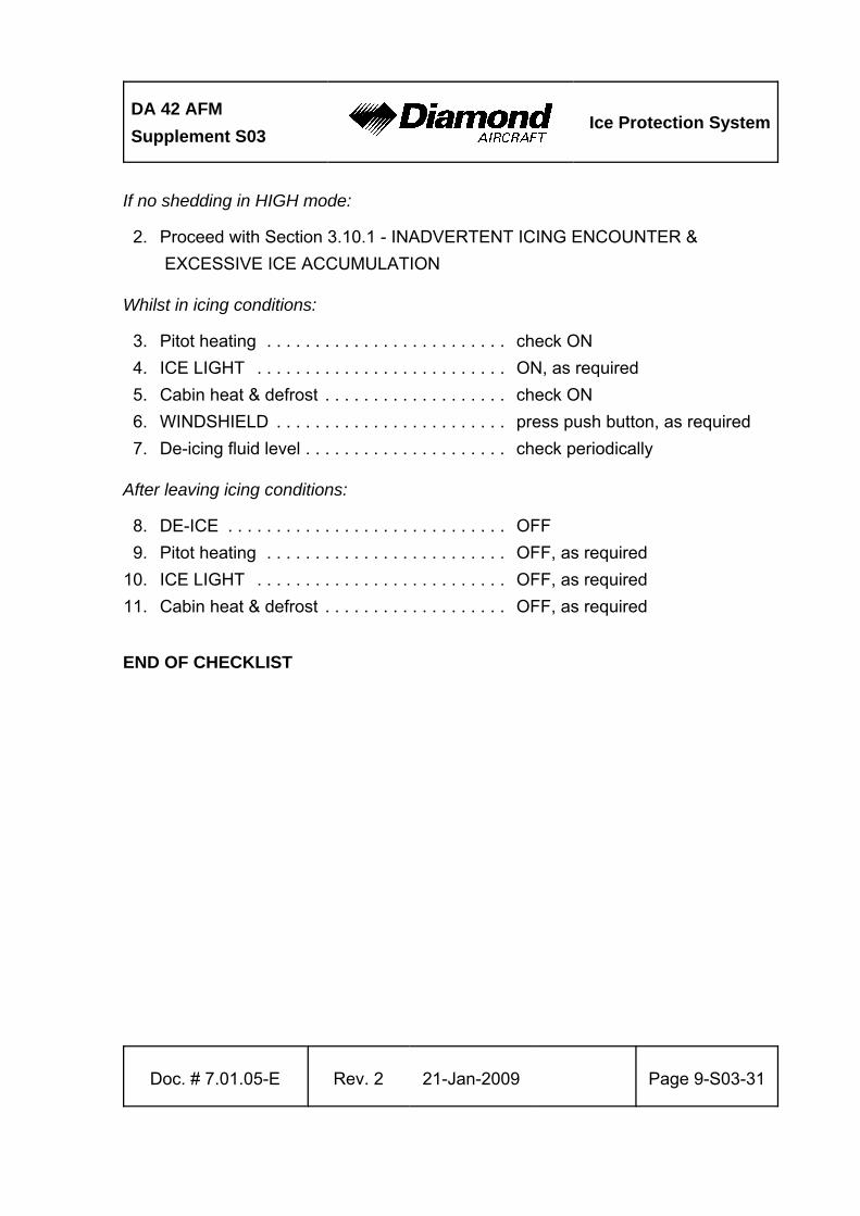
If no shedding in HIGH mode:
2. Proceed with Section 3.10.1 - INADVERTENT ICING ENCOUNTER &
EXCESSIVE ICE ACCUMULATION
Whilst in icing conditions:
3. Pitot heating . . . . . . . . . . . . . . . . . . . . . . . . . check ON
4. ICE LIGHT . . . . . . . . . . . . . . . . . . . . . . . . . . ON, as required
5. Cabin heat & defrost . . . . . . . . . . . . . . . . . . . check ON
6. WINDSHIELD . . . . . . . . . . . . . . . . . . . . . . . . press push button, as required
7. De-icing fluid level . . . . . . . . . . . . . . . . . . . . . check periodically
After leaving icing conditions:
8. DE-ICE . . . . . . . . . . . . . . . . . . . . . . . . . . . . . OFF
9. Pitot heating . . . . . . . . . . . . . . . . . . . . . . . . . OFF, as required
10. ICE LIGHT . . . . . . . . . . . . . . . . . . . . . . . . . . OFF, as required
11. Cabin heat & defrost . . . . . . . . . . . . . . . . . . . OFF, as required
END OF CHECKLIST
Ice Protection SystemDA 42 AFM
Supplement S03
Page 9-S03-32 21- Jan-2009 Rev. 2 Doc. # 7.01.05-E
4A.6.9 CRUISE
If icing conditions do exist:
1. DE-ICE . . . . . . . . . . . . . . . . . . . . . . . . . . . . . NORM, monitor ice build-up
HIGH, if no shedding, or to
prevent excessive ice build up
If no shedding in HIGH mode:
2. Proceed with Section 3.10.1 - INADVERTENT ICING ENCOUNTER &
EXCESSIVE ICE ACCUMULATION
Whilst in icing conditions:
3. Pitot heating . . . . . . . . . . . . . . . . . . . . . . . . . check ON
4. ICE LIGHT . . . . . . . . . . . . . . . . . . . . . . . . . . ON, as required
5. Cabin heat & defrost . . . . . . . . . . . . . . . . . . . check ON
6. WINDSHIELD . . . . . . . . . . . . . . . . . . . . . . . . press push button, as required
7. De-icing fluid level . . . . . . . . . . . . . . . . . . . . . check periodically
8. Airspeed . . . . . . . . . . . . . . . . . . . . . . . . . . . . maintain 121 to 160 KIAS
NOTE
During prolonged icing encounters in cruise, increase engine
power to maintain cruise speed as ice accumulates on the
unprotected areas, and to preclude the ice build-up on the
fuselage under surface.
CONTINUED
DA 42 AFM
Supplement S03Ice Protection System
Doc. # 7.01.05-E Rev. 2 21-Jan-2009 Page 9-S03-33
NOTE
The autopilot may be used in icing conditions. However, every
10-15 minutes the autopilot should be disconnected to detect
any out of trim conditions caused by ice build-up. If significant
out of trim conditions are detected, the autopilot should
remain off for the remainder of the icing encounter so that the
pilot may monitor for additional force build-up.
WARNING
When disconnecting the autopilot with ice accretions on the
airplane, the pilot should be alert for out-of-trim forces. Pilot
control stick input should be applied as required to prevent
potential undesired flight path deviations.
After leaving icing conditions:
9. DE-ICE . . . . . . . . . . . . . . . . . . . . . . . . . . . . . OFF
10. Pitot heating . . . . . . . . . . . . . . . . . . . . . . . . . OFF, as required
11. ICE LIGHT . . . . . . . . . . . . . . . . . . . . . . . . . . OFF, as required
12. Cabin heat & defrost . . . . . . . . . . . . . . . . . . . OFF, as required
END OF CHECKLIST
Ice Protection SystemDA 42 AFM
Supplement S03
Page 9-S03-34 21- Jan-2009 Rev. 2 Doc. # 7.01.05-E
4A.6.11 APPROACH AND LANDING
If icing conditions do exist:
1. DE-ICE . . . . . . . . . . . . . . . . . . . . . . . . . . . . . HIGH
If no shedding in HIGH mode:
2. Proceed with section 3.10.1 - INADVERTENT ICING ENCOUNTER &
EXCESSIVE ICE ACCUMULATION
Whilst in icing conditions:
3. ICE LIGHT . . . . . . . . . . . . . . . . . . . . . . . . . . ON, as required
4. WINDSHIELD . . . . . . . . . . . . . . . . . . . . . . . . press push button, as required
NOTE
De-icing fluid will remain on the windshield for a period after
operating windshield de-ice. For an unobstructed view, do
not operate the windshield de-ice within 30 seconds prior to
landing.
5. Airspeed . . . . . . . . . . . . . . . . . . . . . . . . . . . . maintain 121 to 160 KIAS
until final approach and landing
6. FLAPS . . . . . . . . . . . . . . . . . . . . . . . . . . . . . . UP or APP, as required
Before landing:
7. FLAPS . . . . . . . . . . . . . . . . . . . . . . . . . . . . . . APP
8. Final approach speed . . . . . . . . . . . . . . . . . . min. 82 KIAS
CAUTION
Do not set the flaps to the LDG position. Otherwise the climb
performance may not be sufficient for go-around, and the
safety margin with respect to ICTS will be reduced.
END OF CHECKLIST
DA 42 AFM
Supplement S03Ice Protection System
Doc. # 7.01.05-E Rev. 2 21-Jan-2009 Page 9-S03-35
4A.6.13 AFTER LANDING
1. DE-ICE . . . . . . . . . . . . . . . . . . . . . . . . . . . . OFF
2. ICE LIGHT . . . . . . . . . . . . . . . . . . . . . . . . . . OFF
4A.6.15 EXIT AIRPLANE
CAUTION
When the ice protection system has been enabled in flight,
the walkways on the inner wings may be slippery.
4A.6.17 PARKING
NOTE
When the ice protection system has been enabled in flight,
special care must be taken when touching the airframe
structure or canopy as they may be partially contaminated
with de-icing fluid.
Clean the de-icing fluid from the canopy and the porous
panels. Refer to Chapter 8 for appropriate procedures.
Ice Protection SystemDA 42 AFM
Supplement S03
Page 9-S03-36 21- Jan-2009 Rev. 2 Doc. # 7.01.05-E
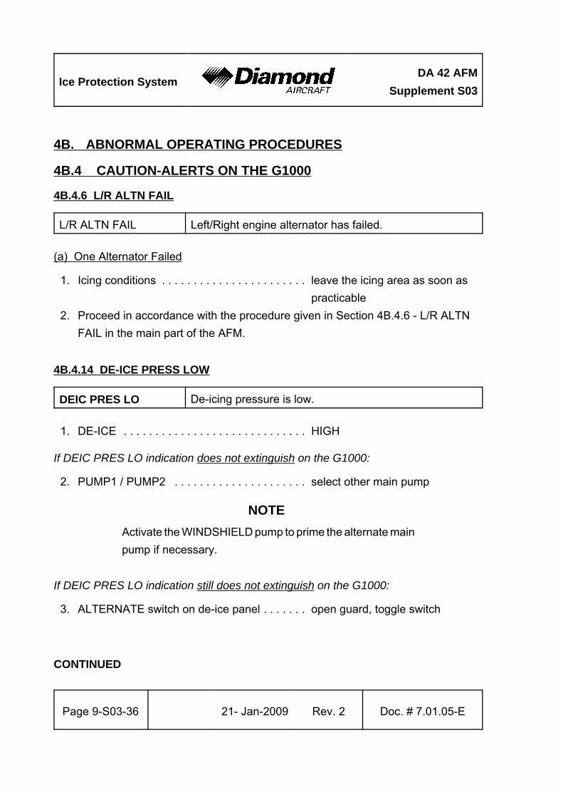
4B. ABNORMAL OPERATING PROCEDURES
4B.4 CAUTION-ALERTS ON THE G1000
4B.4.6 L/R ALTN FAIL
L/R ALTN FAIL Left/Right engine alternator has failed.
(a) One Alternator Failed
1. Icing conditions . . . . . . . . . . . . . . . . . . . . . . . leave the icing area as soon as
practicable
2. Proceed in accordance with the procedure given in Section 4B.4.6 - L/R ALTN
FAIL in the main part of the AFM.
4B.4.14 DE-ICE PRESS LOW
DEIC PRES LO De-icing pressure is low.
1. DE-ICE . . . . . . . . . . . . . . . . . . . . . . . . . . . . . HIGH
If DEIC PRES LO indication does not extinguish on the G1000:
2. PUMP1 / PUMP2 . . . . . . . . . . . . . . . . . . . . . select other main pump
NOTE
Activate the WINDSHIELD pump to prime the alternate main
pump if necessary.
If DEIC PRES LO indication still does not extinguish on the G1000:
3. ALTERNATE switch on de-ice panel . . . . . . . open guard, toggle switch
CONTINUED
DA 42 AFM
Supplement S03Ice Protection System
Doc. # 7.01.05-E Rev. 3› 27-May-2015› Page 9-S03-37
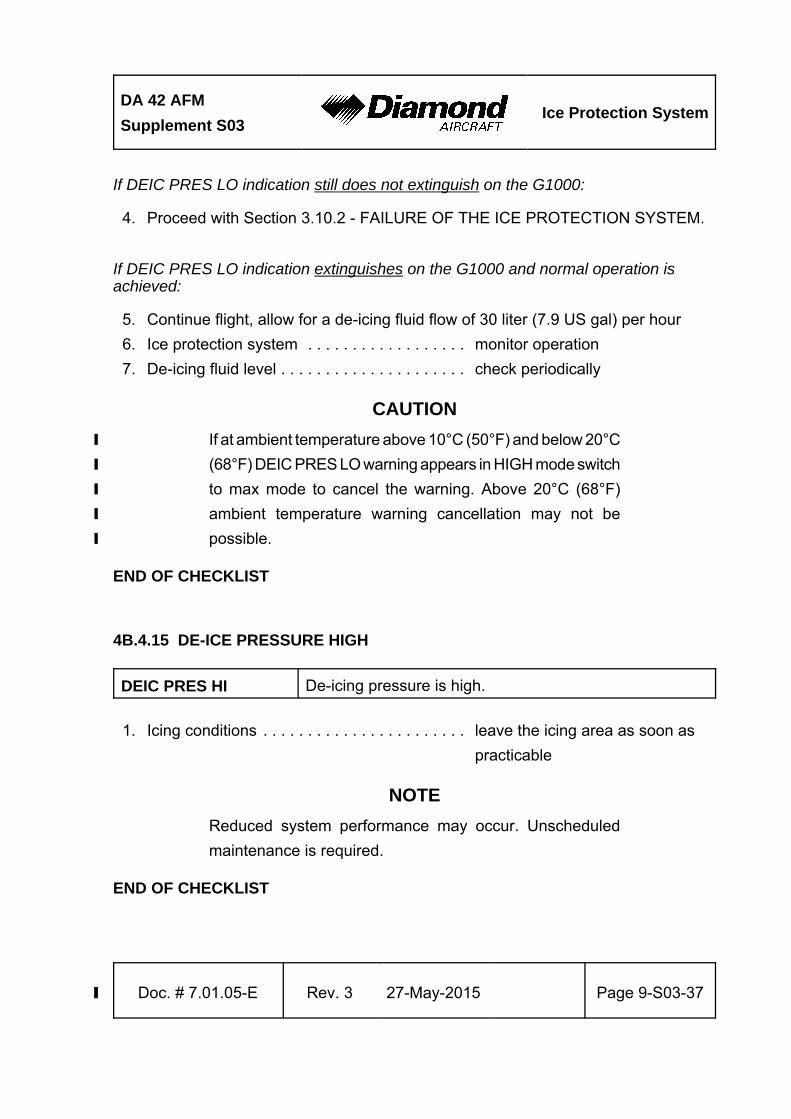
If DEIC PRES LO indication still does not extinguish on the G1000:
4. Proceed with Section 3.10.2 - FAILURE OF THE ICE PROTECTION SYSTEM.
If DEIC PRES LO indication extinguishes on the G1000 and normal operation isachieved:
5. Continue flight, allow for a de-icing fluid flow of 30 liter (7.9 US gal) per hour
6. Ice protection system . . . . . . . . . . . . . . . . . . monitor operation
7. De-icing fluid level . . . . . . . . . . . . . . . . . . . . . check periodically
CAUTION
If at ambient temperature above 10°C (50°F) and below 20°C›
(68°F) DEIC PRES LO warning appears in HIGH mode switch›
to max mode to cancel the warning. Above 20°C (68°F)›
ambient temperature warning cancellation may not be›
possible.›
END OF CHECKLIST
4B.4.15 DE-ICE PRESSURE HIGH
DEIC PRES HI De-icing pressure is high.
1. Icing conditions . . . . . . . . . . . . . . . . . . . . . . . leave the icing area as soon as
practicable
NOTE
Reduced system performance may occur. Unscheduled
maintenance is required.
END OF CHECKLIST
Ice Protection SystemDA 42 AFM
Supplement S03
Page 9-S03-38 21-Jan-2009 Rev. 2 Doc. # 7.01.05-E
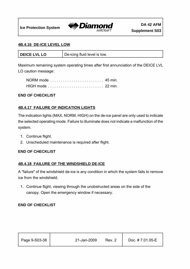
4B.4.16 DE-ICE LEVEL LOW
DEICE LVL LO De-icing fluid level is low.
Maximum remaining system operating times after first annunciation of the DEICE LVL
LO caution message:
NORM mode . . . . . . . . . . . . . . . . . . . . . . . . . 45 min.
HIGH mode . . . . . . . . . . . . . . . . . . . . . . . . . . 22 min.
END OF CHECKLIST
4B.4.17 FAILURE OF INDICATION LIGHTS
The indication lights (MAX, NORM, HIGH) on the de-ice panel are only used to indicate
the selected operating mode. Failure to illuminate does not indicate a malfunction of the
system.
1. Continue flight.
2. Unscheduled maintenance is required after flight.
END OF CHECKLIST
4B.4.18 FAILURE OF THE WINDSHIELD DE-ICE
A "failure" of the windshield de-ice is any condition in which the system fails to remove
ice from the windshield.
1. Continue flight, viewing through the unobstructed areas on the side of the
canopy. Open the emergency window if necessary.
END OF CHECKLIST
DA 42 AFM
Supplement S03Ice Protection System
Doc. # 7.01.05-E Rev. 2 21-Jan-2009 Page 9-S03-39
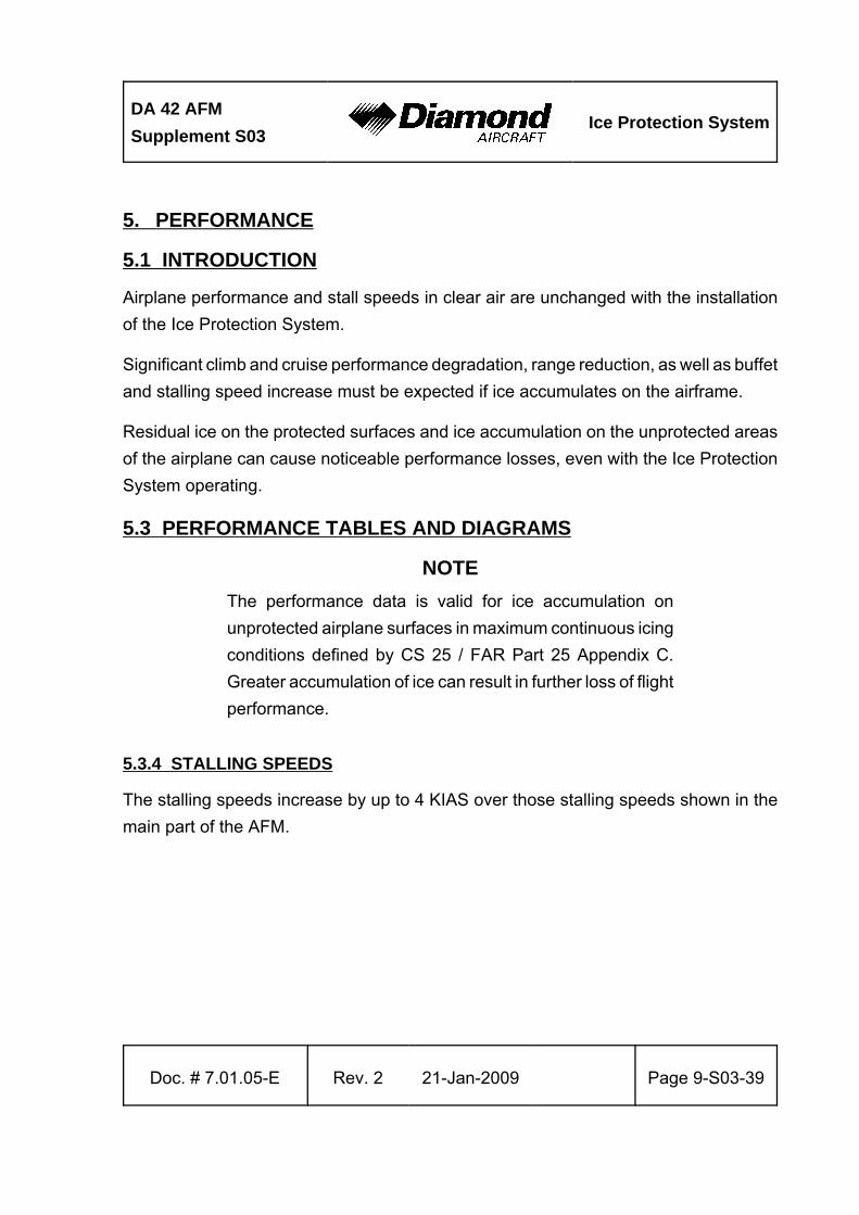
5. PERFORMANCE
5.1 INTRODUCTION
Airplane performance and stall speeds in clear air are unchanged with the installation
of the Ice Protection System.
Significant climb and cruise performance degradation, range reduction, as well as buffet
and stalling speed increase must be expected if ice accumulates on the airframe.
Residual ice on the protected surfaces and ice accumulation on the unprotected areas
of the airplane can cause noticeable performance losses, even with the Ice Protection
System operating.
5.3 PERFORMANCE TABLES AND DIAGRAMS
NOTE
The performance data is valid for ice accumulation on
unprotected airplane surfaces in maximum continuous icing
conditions defined by CS 25 / FAR Part 25 Appendix C.
Greater accumulation of ice can result in further loss of flight
performance.
5.3.4 STALLING SPEEDS
The stalling speeds increase by up to 4 KIAS over those stalling speeds shown in the
main part of the AFM.
Ice Protection SystemDA 42 AFM
Supplement S03
Page 9-S03-40 21- Jan-2009 Rev. 2 Doc. # 7.01.05-E
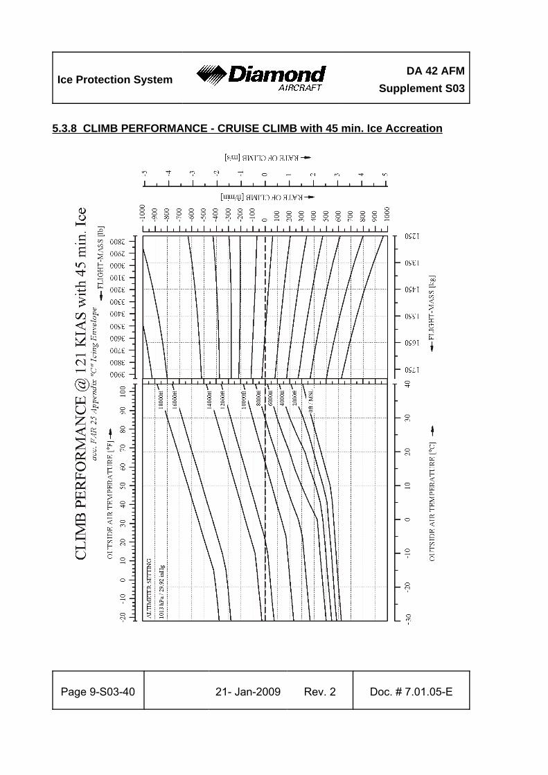
5.3.8 CLIMB PERFORMANCE - CRUISE CLIMB with 45 min. Ice Accreation
DA 42 AFM
Supplement S03Ice Protection System
Doc. # 7.01.05-E Rev. 2 21-Jan-2009 Page 9-S03-41
5.3.9 ONE ENGINE INOPERATIVE CLIMB PERFORMANCE
The one engine inoperative climb performance can be reduced by up to 150 ft/min.
NOTE
Due to ice build-up on unprotected areas and/or residual ice
on the airplane, a positive rate of climb cannot be expected.
5.3.10 CRUISING (TRUE AIRSPEED TAS)
The cruise performance can be reduced by 15 %.
5.3.12 GRADIENT OF CLIMB ON GO-AROUND
The DA 42 reaches a constant gradient of climb of 5.83 % or 529 ft/min under the following
conditions:
- Mass . . . . . . . . . . . . . . . . . . . . . . . . . . . . . . . max. flight mass
(1785 kg/3935 lb)
- Power lever . . . . . . . . . . . . . . . . . . . . . . . . . . both MAX @ 2300 RPM
- Flaps . . . . . . . . . . . . . . . . . . . . . . . . . . . . . . . APP
- Landing gear . . . . . . . . . . . . . . . . . . . . . . . . . extended
- Airspeed . . . . . . . . . . . . . . . . . . . . . . . . . . . . 82 KIAS
- ISA standard conditions at sea level

Ice Protection SystemDA 42 AFM
Supplement S03
Page 9-S03-42 21- Jan-2009 Rev. 2 Doc. # 7.01.05-E
6. MASS AND BALANCE
6.4 FLIGHT MASS AND CENTER OF GRAVITY
6.4.1 MOMENT ARMS
ItemLever Arm
[m] [in]
De-icing fluid tank 1.00 39.4
The mass (weight) of the de-icing fluid is obtained as follows:
Multiply the fluid quantity in liter by 1.1 to obtain kilogram (kg), or
multiply the fluid quantity in US gallon by 9.2 to obtain pound (lb).
DA 42 AFM
Supplement S03Ice Protection System
Doc. # 7.01.05-E Rev. 2 21-Jan-2009 Page 9-S03-43
7. DESCRIPTION OF THE AIRPLANE AND ITS SYSTEMS
7.9 POWER PLANT
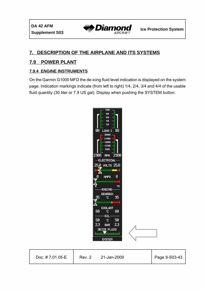
7.9.4 ENGINE INSTRUMENTS
On the Garmin G1000 MFD the de-icing fluid level indication is displayed on the system
page. Indication markings indicate (from left to right) 1/4, 2/4, 3/4 and 4/4 of the usable
fluid quantity (30 liter or 7.9 US gal). Display when pushing the SYSTEM button:
Ice Protection SystemDA 42 AFM
Supplement S03
Page 9-S03-44 21- Jan-2009 Rev. 2 Doc. # 7.01.05-E
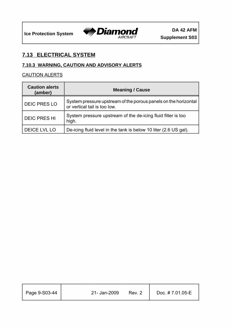
7.13 ELECTRICAL SYSTEM
7.10.3 WARNING, CAUTION AND ADVISORY ALERTS
CAUTION ALERTS
Caution alerts(amber)
Meaning / Cause
DEIC PRES LOSystem pressure upstream of the porous panels on the horizontalor vertical tail is too low.
DEIC PRES HISystem pressure upstream of the de-icing fluid filter is toohigh.
DEICE LVL LO De-icing fluid level in the tank is below 10 liter (2.6 US gal).
DA 42 AFM
Supplement S03Ice Protection System
Doc. # 7.01.05-E Rev. 2 21-Jan-2009 Page 9-S03-45
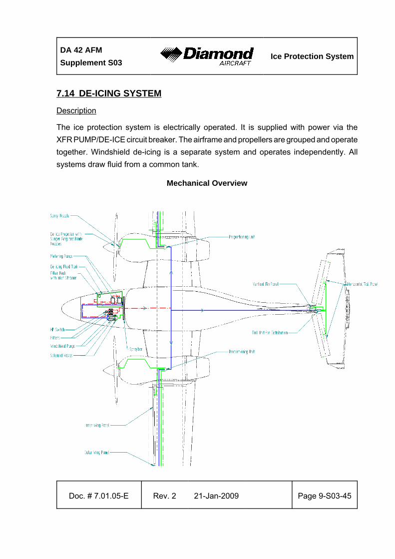
7.14 DE-ICING SYSTEM
Description
The ice protection system is electrically operated. It is supplied with power via the
XFR PUMP/DE-ICE circuit breaker. The airframe and propellers are grouped and operate
together. Windshield de-icing is a separate system and operates independently. All
systems draw fluid from a common tank.
Mechanical Overview
Ice Protection SystemDA 42 AFM
Supplement S03
Page 9-S03-46 27-May-2015› Rev. 3› Doc. # 7.01.05-E
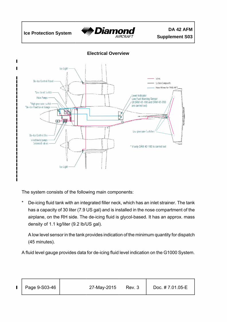
Electrical Overview
›
›
››››››››››››››››››››››››››››
The system consists of the following main components:
* De-icing fluid tank with an integrated filler neck, which has an inlet strainer. The tank
has a capacity of 30 liter (7.9 US gal) and is installed in the nose compartment of the
airplane, on the RH side. The de-icing fluid is glycol-based. It has an approx. mass
density of 1.1 kg/liter (9.2 lb/US gal).
A low level sensor in the tank provides indication of the minimum quantity for dispatch
(45 minutes).
A fluid level gauge provides data for de-icing fluid level indication on the G1000 System.
DA 42 AFM
Supplement S03Ice Protection System
Doc. # 7.01.05-E Rev. 2 21-Jan-2009 Page 9-S03-47
* Two main pumps, installed in the nose compartment of the airplane, under an
inspection lid on the RH side.
The pumps take de-icing fluid from the tank and feed it to :
- the airframe ice protection system (see below), and
- the windshield de-icing system (see below).
In the NORM mode both main pumps run simultaneously and are cycled on and off by
two time delay relays.
In the HIGH mode only the selected main pump runs continuously.
In the MAX mode both pumps run simultaneously and
continuously.
A switch in the cockpit selects the modes NORM and HIGH. In the HIGH mode the MAX
mode can be engaged by pressing a push button on the de-ice panel in the cockpit. This
mode is activated for 2 minutes.
The information which mode is currently in use is indicated by three lights on the ice
protection control unit on the instrument panel.
* The airframe/propeller ice protection system consists of the following components:
- Two de-icing fluid filters, installed in the nose compartment of the airplane, under
an inspection lid on the LH side. The active main pump feeds the de-icing fluid
through the filters to the proportioning units. The filters prevent the proportioning
units from fouling.
Ice Protection SystemDA 42 AFM
Supplement S03
Page 9-S03-48 21- Jan-2009 Rev. 2 Doc. # 7.01.05-E
- Proportioning units in each nacelle (between the main spars) and in the upper
vertical tail (forward of the front spar). The proportioning units regulate the flow
of de-icing fluid to the porous panels and to the propeller slinger rings by means
of capillaries.
- TKS porous panels are fitted to the leading edge of the outer wings, the vertical
tail, and the horizontal tail. The porous panels weep the fluid at a low rate through
fine holes.
- Nozzles and slinger rings on the propellers. The nozzle sprays fluid into the slinger
ring which is mounted to the spinner backplate. The fluid is then distributed to the
propeller blades by centrifugal force through notches in the slinger ring.
- Three low pressure sensors which detect malfunctions of the system. Refer to
Section 7.10 in this Supplement.
- One high pressure sensor which activates an indication when the filter cartridges
need to be replaced. Refer to Section 7.10 in this Supplement.
* The windshield ice protection system consists of:
- Two windshield de-icing pumps with solenoid valves, installed in the nose
compartment of the airplane, under an inspection lid on the LH side. The active
windshield de-icing pump supplies the fluid to the spraybar.
Only one windshield de-icing pump is operative at a time. A switch in the cockpit
selects the active pump (PUMP1/PUMP2). The second pump is installed for
redundancy.
- One de-icing fluid spraybar for the canopy.
Unlike the airframe de-icing system, the windshield de-icing system does not spray
fluid continuously, but is activated for 5 seconds by operating a push button, even when
the main switch of the Ice Protection System is in the OFF position.
DA 42 AFM
Supplement S03Ice Protection System
Doc. # 7.01.05-E Rev. 2 21-Jan-2009 Page 9-S03-49
* The electrical system consists of:
- An ice protection control box which is mounted under the LH baggage compartment
floor. The ice protection control box contains all necessary relays to operate and
cycle the pumps.
- A de-ice panel, mounted on the RH side of the instrument panel, enables the
complete control of the whole de-icing system.
- Two ice lights, one for each wing, are installed for monitoring ice accretion on the
wings in low lighting conditions.
Replenishing
Refer to Section 2.17 in this Supplement for approved de-icing fluids.
NOTE
The de-icing fluid must be considered for the mass and
balance calculations. Refer to Chapter 6 in this Supplement.
De-icing fluid is replenished through the filler which is located in the fuselage nose on
the RH side, aft of the nose baggage door. The tank has a usable capacity of 30 liter
(7.9 US gal).
Operation
The system is operated through four toggle switches and two push buttons located on
the ice protection control unit in the RH section of the instrument panel.
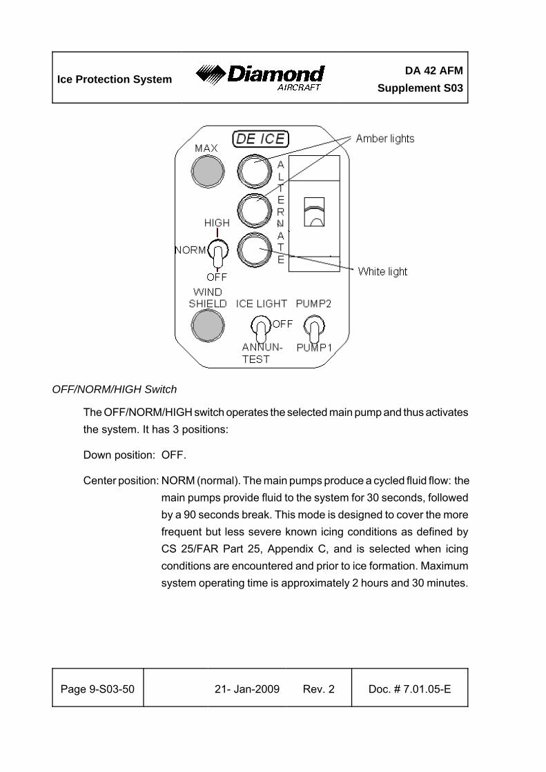
The current operating mode is indicated by the following indication lights:
NORM : lower white light only
HIGH : center amber light only
MAX : both (top and center) amber lights
Ice Protection SystemDA 42 AFM
Supplement S03
Page 9-S03-50 21- Jan-2009 Rev. 2 Doc. # 7.01.05-E
OFF/NORM/HIGH Switch
The OFF/NORM/HIGH switch operates the selected main pump and thus activates
the system. It has 3 positions:
Down position: OFF.
Center position: NORM (normal). The main pumps produce a cycled fluid flow: the
main pumps provide fluid to the system for 30 seconds, followed
by a 90 seconds break. This mode is designed to cover the more
frequent but less severe known icing conditions as defined by
CS 25/FAR Part 25, Appendix C, and is selected when icing
conditions are encountered and prior to ice formation. Maximum
system operating time is approximately 2 hours and 30 minutes.
DA 42 AFM
Supplement S03Ice Protection System
Doc. # 7.01.05-E Rev. 2 21-Jan-2009 Page 9-S03-51
Up position: HIGH. The active main pump produces a continuous fluid flow.
This mode is designed to cover all known icing conditions as
defined by CS 25/FAR Part 25, Appendix C, and is selected when
icing conditions are more demanding or if ice has already
accumulated. Maximum system operating time is approximately
1 hour.
MAX Push Button
The upper push button activates the MAX mode of the ice protection system when
the system is presently in the HIGH mode. This mode is designed to provide
maximum possible protection for conditions outside the icing envelope as defined
by CS 25/FAR Part 25, Appendix C, and is only active for 2 minutes after each
activation. In this mode both pumps are active simultaneously and provide fluid
to the system. Maximum system operating time with continuous MAX mode
activation is approximately 30 minutes.
PUMP1/PUMP2 Switch
The RH bottom switch selects one of the two main pumps and one of the two
windshield pumps. It has 2 positions.
Down position: PUMP 1. Main pump no. 1 is selected as the active pump in
HIGH mode. Pump no. 2 is standby. Also windshield pump no.
1 is selected in case the windshield switch is activated.
Windshield pump no. 2 is inoperative.
Up position: PUMP 2. Main pump no. 2 is selected as the active pump in
HIGH mode. Pump no. 1 is standby. Also windshield pump no.
2 is selected in case the windshield switch is activated.
Windshield pump no. 1 is inoperative.
Ice Protection SystemDA 42 AFM
Supplement S03
Page 9-S03-52 21- Jan-2009 Rev. 2 Doc. # 7.01.05-E
WINDSHIELD Push Button
The WINDSHIELD push button activates the selected windshield de-icing pump
for a duration of 5 seconds. During this time it feeds de-icing fluid to the spraybar
in front of the canopy.
The windshield de-icing works even when the OFF/NORM/HIGH switch of the ice
protection system is set OFF. Purging air from the ice protection system is also
provided from these pumps by continuously pressing the WINDSHIELD push button.
ALTERNATE Switch
The ALTERNATE switch connects the main pump no. 2 directly to the RH main
bus. Thus, in case of a total loss of the LH main bus in icing conditions, operation
of the ice protection system similar to the HIGH mode is possible.
ANNUN-TEST/OFF/ICE LIGHT
This switch activates either both ice-lights or the annunciation test procedure (refer
to Section 4A.6.1).
DA 42 AFM
Supplement S03Ice Protection System
Doc. # 7.01.05-E Rev. 2 21-Jan-2009 Page 9-S03-53
8. AIRPLANE HANDLING, CARE AND MAINTENANCE
The porous panels can be cleaned with soap and water using a clean, lint-free cloth.
Isopropyl alcohol, ethyl alcohol or methylated spirit may be used to remove oil or grease.
Furthermore approved de-icing fluids, AVGAS and jet fuel are permitted for use on the
panels.
CAUTION
Do not apply polish or wax to the panels. Certain solvents,
particularly methyl ethyl ketone (MEK), acetone, lacquer
thinner and other types of thinners and solvents damage the
inner membrane of the panels. Mask active area of panels
with a low tack tape when using solvents or painting the
airplane in the proximity of the panels or when the airplane
is stored in a dusty environment.
NOTE
The ice protection system should be checked for excessive
de-icing fluid leaks after each use. Due to the dihedral wing
small amounts of de-icing fluid can evaporate from the inner
wing panels over a period of several days. Contamination
precautions must be done if the airplane is stored in a hangar.
Ice Protection SystemDA 42 AFM
Supplement S03
Page 9-S03-54 21- Jan-2009 Rev. 2 Doc. # 7.01.05-E
8.4.5 REPLENISHMENT OF THE DE-ICING FLUID TANK
For approved de-icing fluids refer to Chapter 2 LIMITATIONS. The tank is located in the
baggage compartment and the filler cap is on top of the filler neck of the tank, accessible
via the open RH baggage door.
To preclude the possibility of contaminated fluid do not remove the inlet strainer, always
clean the top of the fluid tank before replenishing. Secure the filler cap immediately after
replenishment.
8.6.6. PROLONGED OUT OF SERVICE OR DE-ICING SYSTEM RUN DRY
To avoid the need to reprime the system and to provide a quick response when turned
to service, maintain at least 2 liter (0.5 US gal) in the tank. To ensure that all system
components are filled with fluid, operate the system at least once in a month. If necessary,
operate the pumps until all air is purged from components and pipelines.
Priming of the Main Pumps
The main pumps may not be self priming and are primed, when required, by the operation
of either windshield pump. Windshield pump 1 or 2 will pri me main pump 1 or 2.
Priming of the Porous Panels
In flight:
WARNING
Priming of the porous panels in icing conditions is not
permitted.
DA 42 AFM
Supplement S03Ice Protection System
Doc. # 7.01.05-E Rev. 2 21-Jan-2009 Page 9-S03-55
Priming of the porous panels is best done during climb or descent, at ambient temperatures
up to 4 °C (39 °F). To prime the porous panels, activate the MAX mode. Repeat the
procedure in intervals of approximately 5 minutes until fluid dissipates from all porous
panels.
By special maintenance:
At ambient temperatures above 4 °C (39 °F), special maintenance may be required to
prime the porous panels.
Ice Protection SystemDA 42 AFM
Supplement S03
Page 9-S03-56 21- Jan-2009 Rev. 2 Doc. # 7.01.05-E
Intentionally left blank.


