ICFILE COP~l NAVAL POSTGRADUATE SCHOOL o Monterey, California THESIS AN EXAMIN~ATION OF THE ADVANCED COMMIVUNICATIONS TECHNOLOGY SATELLITE (ACTS) ANfD ITS1 APPLICATION TO THE DEFENSE DATA NETWORK (DDN) by Stephen C. Horner June 1987 Thesis Advisor: Dan C. Boger Approved for public release; distribution is unlimited. DT1O 9 E D 1.87 9 1 291i
Transcript
ICFILE COP~lNAVAL POSTGRADUATE SCHOOL
o Monterey, California
THESISAN EXAMIN~ATION OF THE ADVANCED COMMIVUNICATIONS
TECHNOLOGY SATELLITE (ACTS) ANfD ITS1APPLICATION TO THE DEFENSE
DATA NETWORK (DDN)
by
Stephen C. Horner
June 1987
Thesis Advisor: Dan C. Boger
Approved for public release; distribution is unlimited.
"6A NAME OF PERFORMING ORGANIZATION 16b OFFICE SYMBOL ?a NAME OF MONITORING ORGANIZATIONS (it applicaIble)
Naval Postgraduate School 74 Naval Postgraduate School
6c ADDRESS (City. Sttef, and ZIPCode) 7b ADDRESS(City, State, and ZIP Code)
Monterey, California 93943-5000 Monterey, California 93943-5000"8a NAME OF FUNDING/ SPONSORING Sb OFFICE SYMBOL 9 PROCUREMENT INSTRUMENT IDENTIFICATION NUMBER
ORGANIZATION (If applicable)
8c ADDRESS(City, State, and ZIP Code) 10 SOURCE OF FUNDING NUMBERS
PROGRAM PROJECT TASK WORK UNITELEMENT NO NO NO JACCESSION NO
11 T;TLE (Include Security C i cah , nAn Examination oF ste icd1vanced Commimications Technology Satellite (ACTS) and itsApplication to the Defense Data Network (DDN)
PERSONAL UTHRR(STC.S)
0orner, ?tepnen C.0 R T 1'3b T"ME COVERED 114 fO °OJ REPORT 'fear. MontD I'u PAGoN!
h ....O.. TO une'6 SL.IE.%!NTARY NOTATION
' _____ /COSAT, CODES 18 SUBJECT TERMS (Continue on reverse it necessary iad ,dent,hy by block nuA ,,ber)
, STRAC (Continue on reverie it necessary and identify by block number)r
This thesis exa;•iines NASA's Advanced Communications Technology Satellite (ACTS) withemphasis on its potential applicability to the Defense Data Network (DDN). The ACTSprogram is a joint NASA industry program to develop the next generation of communicationssatellites, thus assuring the U.S.'s continued pre-eminence in this area. The ACTS willessentially operate as a "switchboard in the sky." The thrust of the thesis is to takea broad-brush look at the system and discuss its applicability to DoD's packet switchingdata network, the DDN. This thesis is written so that a technical background is notrequired by the reader. Applicable background information is provided where necessary.The emphasis is on the concepts involved and a discussion of the interoperability of thetwo systems...
,J0 S'R,3J!.ON,'AVAILABILITY OF ABSTRACT 21 ABSTRACT SECURITY CLASSIFICATION
,.NCLASSIF!iDIUNL;MITED r SAME AS RPT QOTIC USERS UNCLASSIFIEDN2a ",ME OF RESPONSiBLE INDIVIDUAL 22b TEI.PHQ N (Include Area Code) I 22c OFFICE SYMBO.
Dan C. Boger (40 )-6•6-2607 54B0
OD FORM 1473, 84 MAR 83 APR edition reay be used until ehIausted SECURITY CLASSIFICATION CF TIS PAGEAll other edftions are obsolete
1OM
Approved for public release; distribution is unlimited.
An Examination of the Advanced Communications TechnologySatellite (ACTS) and its Application to the
Defense Data Network (DDN)
by
Stephen Clark HornerCaptain, United States Army
B.S., United States Military Academy, 1976
Submitted in partial fulfillment of therequirements for the degree of
MASTER OF SCIENCE IN SYSTEMS TECHNOLOGY(Command, Control and Communications)
from the
NAVAL POSTGRADUATE SCHOOLJune 1987 \
Author: ~eStephen ClarkI-Ibmer
Approved by:
ThomtJ. Brown, Second Reader
MichAel G. Sovereign, ChaJoint Command, Co d 6*ns Academic Group
Acdei Dean,,,•••
2
ABSTRACT
This thesis examines NASA's Advanced Communications TechnologySatellite (ACTS) with emphasis on its potential applicability to the DefenseData Network (DDN). The ACTS program is a joint NASA industryprogram to develop the next generation of communications satellites, thusassuring the U S.'s continued pre-eminence in this area. The ACTS willessentially operate as a "switchboard in the sky." The thrust of the thesis is totake a broad-brush look at the system and discuss its applicability to DoD'spacket switching data network, the DDN. This thesis is written so that atechnical background is not required by the reader. Applicable backgroundinformation is provided where necessary. The emphasis is on the conceptsinvolved and a discussion of the interoperability of the two systems.
A. A CHANGING COMMUNICATIONSENVIRONMENT ........................................................ 10
B. OBJECTIVES ............................................................... 11
C . SCOPE ....................................................................... 11D. ORGANIZATION OF STUDY ..................................... 12
II. COMMERCIAL SATELLITE COMMUNICATIONS--TO D A Y ............................................................................. 13
A. A FEW BASICS ..................... 131. Communications Satellite Orbits ....................... 132. Communicattions Engineering for Satellites ...... 19
B. FROM ARTHUR C. CLARKE TO TODAY ......... 27C. FIBER OPTICS--THE TECHNOLOGY ..................... 31D. THE FIBER OPTIQ IMPACT ON SATELLITE
COMMUNICATION. .. .............. 36
III. COMMERCIAL SATELLITE COMMUNICATIONS-TOMORROW ...... ................. 41
A. SATELLITES RESPONDING TO CHANGE ............. 41B. THE ACTS PROGRAM .......................................... 47C. AN ACTS £EASED COMMERCIAL SCENARIO ......... 56
IV. THE DEFENSE DATA NETWORK (DDN) ....................... 60
A. WHAT IS PACKET SWITCHING ............................ 60B. BACKGROUND ................ 62C. THE DDN SYSTEM ........................... .. 65D. DDN SYSTEM OPERATION...................... 67
4
V. THE ACTS AND THE DDN -- ADISCUSSION .............. 71
B. ASSUM1VPTIIONS ............................... .71*C. APPL..ICATION.) CONCEPTS ................................. 73
D. DDN COMMUNICATIONS SECURITY AND THEA(CTS SYSTEM ..................................... 8
VI. CONCLUSIONS AND AREAS FOR FURTHER STUDY........ 84
A. CONCLUSIONS....................................... 84
B. AREAS FOR FURTHER STUDY .................... 85
APPENDIX: NASA PROOF OF CONCEPT TECHNOLOGIES ........ 86
LI1ST OF REFERENCES .................................................. 88
INTA IIIS11RIBUnII(N LIST .......................................... 92
5
LIST OF TABLES
2.1 Circular Orbital Velocities and Orbital Periods for EarthSatellites at Various Altitudes .................................. ................... 15
2.2 Various Beamwidths with Corresponding Coverage Areas .............. 252.3 Early Communications Satellite Programs .................................... 292.4 Trunking .................................................................................. 393.1 Approximate Long-Haul Cost for Business User ............................ 423.2 VSAT CPS circa 1985 ................................................................ 463.3 ACTS General Information ........................................................ 503.4 Typical ACTS Ground Terminals ................................................ 55
6
ri
LIST OF FIGURES
2.1 Satellite vs. Ground Systems ............. 142.2 Orbital Inclination (Edge View of Orbit) ................................. 162.3 Earth Synchronous Orbits and the Figure Eight of the
Subsatellite Point ................................................................. . 172.4 Geometry of Stationary Orbit ........................ 182.5 Earth Views .................................... .............. ................... . 202.6 Antenna Radiation Pattern and Beamwidth ............................... 222.7 Coverage Contours for a Synchronous Satellite at 300 West
Longitude ........................................................................... . 242.8 FLTSATCOM Constellation and Coverage .................... 232.9 Antenna Beam s ................................................................... . 262.10 Evolution of INTELSAT Satellites ......................................... 302.11 Communications Satellites Trends and Opportunities ..................... 312.12 Light Propagation in Optical Fiber ......................................... 332.13 Basic Fiber Optics Communications System .............................. 342.14 Schematic Illustration of Biconical Design Developed by Bell
Laboratories ......................................................................... 362.15 Potential AT&T Lightwave Transmission Network-- 1995 ...... 383.1 Current Architecture Terrestrial Switching .............................. 433.2 Access to the Fiber Network ............ ..................... ...... 443.3 Satellite Bypass of Public Switched Network ............................. 453.4 Very Small Aperture Terminal (VSAT) CPS ........................... 453.5 Ground Switched Satcom System ............................................. 473.6 ACTS 30/20 GHz Experimental SysLwm (CPS Mode) ................. 523.7 Uplink Beam FDM/TDM Organization ................................... 533.8 The ACTS Optical Intersatellite Links ..................................... 563.9 System Functional Block Diagram (Operational ACTS)* ........... 583.10 4ESS (and Equivalent in ACTS) ............................................. 594.1 Operational Model of an ARPANET-like Network .................... 614.2 The DDN Evolution Strategy .................................................. 644.3 DDN Components ................................................................ 65
7
"-•I•' •I:• • ...
4.4 Interfacing Options for the Host ................................... .64.5 Segmented DDN ................. .. ...................................................... 68
5.1 ACTS Used with the Current DDN System .................................... 745.2 Ground Tenninals Used at Every Host ......................................... 775.3 ACTS System Used with Clustered Hosts ....................................... 78
8
ACKNOWLEDGEMENT
I would like to take this opportunity to thank Professor Dan Boger forhis assistanc.e and guidance in the development and completion of this thesis.His contributions significantly increased the learning value of this effort.Special thanks are extended to Major Thomas J. Brown, USAF, for hisoutstanding effort in making this thesis a better document. Major Brown'sassistance in communications related areas and especially in the workings ofthe Macintosh computer added immeasurably to what I gained from thisexperience. A very special thank you to my wife, Karen, whose typing,assistance., and support made this effort considerably easier.
9
~f\A r~flA f'J. ~ I'.A ,~XA I\At" rr.A1, ,&A zA*~ FLA hA aI .1
1. INTRODUCTION
A. A CHANGING COMMUNICATIONS ENVIRONMENTThe communications field has always functioned within a rapidly
changing environment. In the relatively short period since the early part ofthis century, the communications field has moved from wire line telephonesand radio broadcasts to today's world of global live television, wirelesstelephones, cellular telephones, computing from home, and local areacomputer networks. The technological progress continues as use of light as acommunications medium and other capabilities, such as video telephone callsstart to emerge. These advances have been made possible through the rapidexpansion of technology in computers, integrated circuits, communicationsequipment and the use of space.
The use of space is highlighted because without the contribution of thenumerous communications satellites circling the globe today the extensivecapabilities of the television and communications industry would not Iepossible. It is, therefore, advisable that when a major force impacts on thisvery important area one should take note of the fact and observe the reaction.The major force, in this case, is the emergence of fiber optics in thecommercial industry marketplace as a competitor for the communicationstraffic carried by satellites. The reaction from the communications satelliteindustry has been to perform a comprehensive evaluation of the satellite'srole in meeting future communif~ations needs. The product of this evaluationwill incorporate state-of-the-brt zommunications technology and theunique advantages of satellite communications. The objective will be toprovide the commercial satellite industry a new and dynamic system that iscompetitive in the communications marketplace. The military, as a majoruser of satellites, both military and commercial, for communicationspurposes, will be affected by this evolution of satellite use and must beprepared for its onset. This evolution of satellite technology is beingspearheaded by the National Aeronautics and Space Administration (NASA)and the communications satellite industry. This joint development effort has
10
been designated the Advanced Communications Technology Satellite(ACTS). This thesis will delve into this currently emerging area of satellitecommunications.
B. OBJECTIVESThe primary objective of this thesis is to examine the NASA-industry
communications development program, the ACTS program, and its possibleapplication to the Defense Data Network (DDN). The secondary objective isto provide the readIer current information on areas associated with theprimary objective to support further studies of related issues.
C. SCOPEThis thesis will focus on the concepts involved in the NASA-industry
program and its applications to the DDN. The thrust of this effort is a broaddiscussion of the pertinent systems and concepts and not a detailedexamination of the technology or communications concepts involved.Detailed information may be provided to the reader as backgroundinformation or to support the understanding of other concepts. By focusingon a more general discussion it is intended that the information assembled, itssubsequent discussion, and the conclusions drawn will lead to further moredetailed studies in this area.
This thesis will not attempt to determine or comment on the feasibilityor appropriateness of the ACTS program in general. The ACTS programexists as an active program within NASA, and the information provideddescribes that program. For discussion purposes within this thesis,inform-ation referenced from sources which may be viewed as biased towardthe program will be accepted. A more detailed look at the subject area mayrequire a more comparative analysis to determine the validity of thisinfor mation. As a final note, it should be remembered that the ACTSprogram is an experimental program and some assumptions made orconclusions drawn by some sources may be changed as a result of furtherevaluation of the system.
kitji WA MUU 4ý- *,I WWUw" , NMUat11t
D. ORGANIZATION OF STUDY
The succeeding chapters will examine those areas that will provide theinformation needed to discuss the application of the NASA-industryprogram to the DDN. The first two charters will provide an overview of thecommercial satellite industry. The emphasis in the first chapter is on theevolution of current satellite systems. It also provides some backgroundinformation related to space communications systems. The second chapterlooks at tomorrow's outlook for the communications satellite with emphasison the NASA-industry ACTS program. After this overview of commercialsatellites, an overview of the DDN follows in the next chapter. This providesa broad look at the DDN's evolution, components, and operation. Chapter Vdiscusses the application of the ACTS system to the DDN. Finally, ChapterVI highlights the conclusions reached in the thesis and outlines areas forfurther study.
12
II. COMMERCIAL SATELLITE COMMUNICATIONS--TODAY
To understand where commercial satellite communications is going it isimportant to understand how it got where it is. This chapter will brieflyexamine the evolution of satellite communications from the beginning totoday and how the emergence of fiber optics has affected the satellite role.However, 3efore examining these areas, it is important for the reader tounderstand a few basics about satellite orbits and satellite communicationsengineering concepts.
A. A FEW BASICSThe intent of this section is not to go into detail about orbital mechanics
or communications engineering. The focus is to briefly discuss those mainpoints that will allow the reader to gather the maximum benefit frominformation presented throughout this thesis. In later chapters these topicareas will be expanded where necessary to provide further information inspecific areas.
1. Communications Satellite OrbitsThe importance of satellites as communications platforms is readily
apparent by examining the simple illustration at Figure 2.1. In Figure 2.1 a,the path between two of the transmitting/receiving stations is approximately30 miles. This path, known generally as the radio line of sight (LOS), isdirectly determined by the curvature of the earth. Of course, buildings,mountains or other obstructions can affect the radio LOS, making it longeror shorter, but a ground to ground clear path between two idoirnts isapproximately 30 miles [ Ref. I p. ? . Therefore, a telepione callbetween Los Angeles and New York would have to cross many such systemsto complete the circuit. It is apparent from further study of Figure 2.1a thatas either station, or both, are further elevated the maximum radio LOSdistance between the two stations increases. This simple concept is the basis
13
for the importance of today's communications satellites, as illustrated inFigure 2.l1b.
As stated, the height of the receiving/transmitting or relay stationdirectly affects the possible LOS distance between two end stations. Theconstruction of immense towers, or the use of balloons or aircraft were notfeasible long term. answers. The ar.; ier was a platform that maintained arequired altitude without continuous adjustment or power requirement (forinstance, jet engines). A satellite in orbit was looked to as an effectivesolution to the problem. However, using the satellite as a communicationsplatform subjects it to the same laws of nature and forces that affect the moonas a satellite of the earth and the Earth as a satellite of the sun. While notdelving deeply into the mechanics of satellite orbits, suffice it to say that thereare almost an infinite number of orbits available to a satellite, butcommunications considerations limit the usable choices to a relative few.
MICROWAVE ANTENNA.'%'
a. Microwave relay towers located 25 to 30 miles b. Use of satellite as radio-wave relay
(Earth~ curvature is exaggerate; satellite can connect stations farther apart than 60 miles)
Figure 2.1 Satellite vs. Ground Systems [ Ref. 1: p. 2]
A basic statement of the orbital mechanics involved with satellites -isthat the closer they are to the earth, the smaller their time to orbit the earth,called their orbital period. Table 2.1 shows some examples of orbital periodsfor various circular orbits. The orbital period is a key consideration in theengineering of satellite communications systems. From Table 2.1, a satellite
14
at 1000 miles above the earth will orbit the earth approximately 12 times in atwenty-four hour period. This i. not ideal for most applications ofcommunications satellites because of the loss of signal as the satellite passesout of the LOS of ground stations and the delay until contact is reestablishedon the next orbit. Additionally, if multiple satellites are used to insureconnectivity, the requirement to hand off the communications signal fromsatellite to satellite increases the complexity and cost of the system.
TABLE 2.1 CIRCULAR ORBITAL VELOCITIES AND ORBITALPERIODS FOR EARTH SATELLITES AT VARIOUSALTITUDES [ Ref. 1: p.52]
ALTITUDE VELOCITY PERIOD
KILOMETERS MILESKILOMETERS MILES PER SECOND PER SECOND
0 0 7.91 4.92 1 h 24.3 min161 100 7.80 4.85 1 h 27.7 min
322 200 7.70 4.79 1 h 33.8 min644 400 7.53 4.68 1 h 37.5 min
1609 1000 7.06 4.39 1 h 57.7 min
8045 5000 5.26 3.27 4 h 46.6 min35,880 22,300 3.07 1.91 24 h
However, if the satellite is moved out to an altitude ofapproximately 22,300 miles, the orbital period of the satellite becomes 24hours (Table 2.1). Now the satellite has an orbital period that corresponds tothe period of the earth's rotation. This is called a geosynchronous orbit. Avariation of the geosynchronous orbit is called a geostationary orbit both willbe further described in the following paragraphs. These orbits greatlysimplify the engineering aspects of the communications system. This is notto say that other orbits are not used for communications. However, by farmost communications satellites in use today are in a geosynchronous orbit.Orbits at lower altitudes are generally used for reconnaissance, navigation,surveillance, land/ocean resources, or meteorological satellites.
The orbital altitude is one factor impacting orbit selection forcommunications satellites. The second factor is orbital inclination. The
orbital inclination is the angle formed by the intersection of the plane of theorbit with the plane passing through the earth's equator. Figure 2.2 showsan example of this concept. The importance of the orbital inclination will bediscussed only with respect to geosynchronous satellites. "1
.EAh n INCLINATIN OF ORBrT
Figure 2.2 Orbital Inclination (Edge View of Orbit)
The earth is not a perfectly round ball , rather, it bulges around theequator. This bulge of the earth causes perturbations in the orbits of allsatellites about the earth as a result of the variation in gravitational forces[ Ref. 1: pp. 73-74 ]. For the geosynchronous orbit, the perturbationsare as shown in Figure 2.3. The figure eight shown is the ground trace ofthe satellite path on the earth, or what is called the subsatellite point. Themore inclined the orbit of the geosynchronous satellite the larger the figureeight. Therefore a geosynchronous orbit remains over a specific area on theearth depending on its orbital inclination. As the size of the figure eightincreases, so does the complexity of ground operations to maintain satellitetracking and communications quality. Therefore, the object of mostcommunications providers is to make the figure eight as small as possible.To negate the effect of the earth's bulge as much as possible, the inclination ofthe orbit must be zero. Therefore, the combination of these two factors, thealtitude of the orbit (22258.94 mi) and its inclination (00) provide theprimary orbit for communications satellites about the earth. This orbit,because it has a 24 hour period, is geosynchronous. The fact that k also haszero degrees orbital inclination, or orbits the earth along the equator, makes
16
, ., . M , i n S n a inn n-t1
az..J1h1 * Z~j SL. 4.t~t~t A~t
the orbit geostationarl. A geostationary orbit remains over a specific pointon the earth because it is at zero inclination.I Ref. 2: pp. 3-36, 3-40, 3-41 ]
The inherent stability of the geostationary orbit is not the onlyadvantage gained from a communications perspective. From Figure 2.1, itwas shown that to connect two distant points on the ground a relay wasneeded at a height where both stations would have LOS to the relay station.The higher the relay, or in this case the satellite, the farther the end pointscould be from each other. The geostationary satellite combines the advantageof being over the same point on the ground continuously with being able to
IN~CLINED iSTATIONARY
EQAORA PLANE
- -'STATIONARY IN~CLIN~EDEQUATORIAL ORBITS i, I
Figure 2.3 Earth Synchronous Orbits and the Figure Eight of the
Subsatellite Point [ Ref. 2: p. 3-43 ]
see an immense area on the ground. This area is known as the satellite's fieldof view (FOV). For a geostationary satellite it is approximately one-third ofthe earth's surface. Figure 2.4 shows the geometry of the geostationaryorbit, highlighting the fact that a constellation of three satellites wouldprovide coverage for almost the entire earth. The polar regions of the earth,shown as the shaded no coverage area in Figure 2.4, are affected by thecurvature of the earth that blocks them from the satellite's fields of view.
17
VELOCrrY 6.88 MPS>
17.34 DEG
4- 25946 MI
45456 MI
"7294 MI
SOV ERLA P AREA sa diliC,,,1,,,,,111111 NO COVERAGE (POLAR AREAS)
NOTE: EARTH VIEWED FROM POLE
Figure 2.4 Geometry of Satellite Orbit [ Ref. 2: p. 2-5]
18
Figure 2.5a depicts what a satellite would see from approximatelygeostationary orbit (22,000 mi). Areas above 81.250 north and south are notseen [ Ref. 2: p. 2-4 ]. The reader will notice from the figure that the twopolar regions are not visible to the satellite. This is reinforced by examiningFigure 2.5b, which shows a view of the earth from approximatelygeosynchronous orbit at an orbit inclination of 200 (200 North latitude).The polar area is clearly visible from this position. While mostcommunications satellites use geostationary orbits, the requirements toprovide service to areas not covered from that orbit may require the use ofother orbits not discussed here.
2. Communications Engineering for SatellitesCommunications engineering for satellites, like satellite orbits, has
some basic concepts, terms, and realities that provide a foundation forunderstanding satellite systems. As described above, the satellite provides thecapability to extend the range of communications systems without numeroussystem links. The satellite, in its most commonly used form, is a high altituderelay or repeater station. A commonly used expression for a satelliteoperating in this manner is bent pipe operation. The satellite merelyreceives the incoming electromagnetic radiation from the transmittingground terminal and lets it flow &-rough the bent pipe to the appropriatereceiving ground terminal. Although essentially correct, the operation is notquite that simple. The energy transmitted from the ground station hasdiminished by the time it reaches the satellite due to path loss. The satellitemust amplify the energy received prior to transmitting to the groundterminal to insure that the receive signal level at the ground terminal issufficient to support communications. Additionally, to prevent interferenceand feedback at the satellite the frequency of the incoming signal must bechanged prior to retransmission. Therefore, in addition to the reception andtransmission of the signal, the relay satellite must first change the frequencyand then amplify the signal prior to retransmission. The transmission of thedownlink signal in response to an uplink signal is the function of atransponder. The number of transponders on satellites has increased with theadvance of satellite technology thereby increasing communications capacity.
19
a. Earth View from Satellite in GeosynchronousOrbit over the Equator (00 Latitude)
300 N. Latitude
- 15* N. Latitude
4*--EnUATOR
b. Earth View from Satellite in GeosynchronousOrbit at 200 North Latitude
Figure 2.5 Earth Views
20
The basic bent pipe relay satellites are giving way to the moresophisticated processing satellites. A processing satellite acts upon theincoming signal, other than changing frequencies or amplification, prior toretransmission of the data. This may take the form of reformatting the data,switching the uplink data to different downlink paths depending on thedestination of the signal or switching individual channels to different paths.The concept of a processing satellite will be more fully examined inChapter I1. [ Ref. 3: p. 4 ]
To understand tho' inmportance of the satellite's communicationsarea coverage to its mission and capabilities, a brief discussion of antennabasics is required. The antenna is basically an interface between theelectronic circuit and the outside electromagnetic field. The antennaconverts the current or voltage to electromagnetic waves at the transmitterand vice versa at the receiver. A key feature of an antenna is its radiationpattern. The radiation pattern is a representation of the intensity of theantenna radiation in a given plane. For example, Figure 2.6a shows theradiation plot for an omnidirectional antenna. Omnidirectional means thatthe relative strengtl, of the antenna power density is constant at a givendistance from the antenna in any direction. Figure 2.6b shows a moredirectional pattern with a major lobe towards the top of the page and severalminor lobes around tht bottom side. This indicates that the major powerdensity is concentrated towards the top of the page. This pattern changes fordiffetent types of antennas. [ Ref. 4: pp. 511-513]
A comnionly used term when discussing antennas and a term whichis important in engineer ng conimtmications systems is antenna gain. Thegain for a particular antennd is the ratio of the maximum power density ofthat antenna to the maximum power density of a reference antenna in a givendirection (usual*y tht. max). For the most part, the reference antenna usedis an istropic point radiator (ISR), i.e., ormidirectional. The value for theISR is determi.Led by dividing tue maximum power transmitted by thevolume of a sphert, wiLh a radius that encloses the antenna. The gain of anantenna is normally expressed in decibels. Since the antenna is a passivedevice and does not create power, the term gain may be misleading Simplyput, the power that is radiated in all directions, as an ISR represents, is shaped
21
and focused by the particular antenna. This increases the power radiated in aspecific direction, thereby producing an effective gain of power in thatdirection. For an antenna of a given size the higher the operating frequenciesthe higher the gains that are practical. (Ref. 4: pp. 514-515)
Beamnwidth%
a. Omnidirectional b, Directional c. Antenna PattenRadiation Pattern Radiation Panern Beamwidth
Figure 2.6 Antenna Radiation Pattern and Beamwidth [ Ref. 4: pp. 513, 516 ]
A brief discussion of antenna beamwidth will close this detailedlook at antennas. The beamwidth is defined as "the angular separationbetween the two half-power points (3dB down from maximum) of theradiation pattern in a given plane" ( Ref. 4: p. 516 ]. Figure 2.6c shows asimple illustration of the beamwidth for a typical antenna power radiationpattern. A trade off exists between the beamwidth and the gain of theantenna. Antennas having a narrower beamwidth have greater gains and viceversa [ Ref. 4: p. 516].
The altitude of the satellite is not the only factor in determining thecommunications coverage area of the satellite. The coverage area is heavilyinfluenced by the capabilities of the communications systems aboard thespacecraft. Antennas that can cover the earth's surface as viewed fromgeostationary orbit are known as earth or global coverage antennas. Thisname is somewhat of a misnomer because the antennas only see about a thirdof the earth. They do not cover the polar areas and the actual antenna beam:,.alistically covers an even smaller area [ Ref. 2: p. 2-4 ].
As previously mentioned, the farthest north and south that asatellite can see from a geostationary position is 81.250. At this latitude the
22
satellite would appear to be on the horizon to the satellite terminal. It is ageneral rule of thum:b to not expect high performance from a terminal whoseelevation angle to the satellite is less than 100 ( Ref. 2: p. 2-4 1.Figure _2 7(on page 24) outlines the actual coverage for a geostationarysatellite at 30' West longitude. The contour line drawn for terminals with a10° elevation angle shows thlat coverage is possible for close to one-third ofthe earth's circumference. However, in the vicinity of the 600 latitude linesthe coverage area contracts due to the elliptical shape of the projecteddownlink pattern of the antenna beam. Although the pattern could beadjusted to account for the problem, the general rule of 100 elevation is stillpractical. To alleviate the problem, a four satellite constellation is used toprovide the global coverage except for polar regions. An example of this isshown at Figure 2.8. [ Ref. 2: p. 2-4]
Figure 2.8 FTSATCOM Contellation ad Coeae[ e.2Tp -
SatelliLe mission requirements do not always demand that earthcoverage antennas be used. In fact, it is at times more desirable to have asmaller area of coverage. These antennas are known as narrow beam or spotbeam antennas. These spot beams may range in size from relatively small
23
150 ELEVATION '0QELEVATION
600
Figure 2.7 Coverage Contours for a Synchronous Satellite at300 West Longitude [ Ref. 2: p. 2-6 ]
24
ELEVTIO
beams that are used with a multiple beam or beam hopping antenna system toa large spot beam that covers just one country. Table 2.2 shows severalexamples of spot beam diameters for given antenna beamwidth atgeostationary orbit. Figure 2.9 illustrates examples of the different types ofbeams. The narrower the beam the higher the gain within the footprint, orspotbeam coverage area. This decreases the size of the ground terminalantenna required because the required receive signal levels can be achievedacross a smaller antenna area with the higher gain. Power from groundterminals to satellites is not usually a problem because the transmit powercapabilities for most ground terminals are not faced with the same cons',aints(i.e. size, weight, radiation effects, etc.) as satellite systems.
TABLE 2.2 VARIOUS BEAMWIDTHS WITH CORRESPONDINGCOVERAGE AREAS [ Ref. 3: p. 127]
EAR1"NBEAMWIDTH COVERAGE DIAMETER
(MIES)100 3921
5.70 2235
2.80 1117
1.00 392.570 223
Before closing this section, a brief description of three keytechniques in understanding satellite communications will be provided. Theyare frequency division multiple access (FDMA), time division multipleaccess (TDMA), and demand assigned multiple access (DAMA). All three ofthese techniques are important ways the satellite and the ground terminalstalk to each other.
In FDMA each earth station is assigned a specific frequency onwhich to transmit and receive within the bandwidth of the satellite.Therefore, there may be multiple stations accessing the same satellite at thesame time but because they are at different frequencies there is n ointerference. This is the simplest of the three accessing techniques and it is
25
SPOT BEAMSGLOBAL ANTENNA
18
MULTIPLE
SPOT BEAMS
Figure 2.9 Antenna Beams [Ref. 3: p. 127]
26
used the most. In TDMA, instead of each earth station assigned a differentfrequency, the stations are assigned a different time slot. Therefore, allstations operate on the same frequency but only at different times. This typeof technique requires much greater precision and control and requires shortburst communications. DAMA is not a separate technique from FDMA orTDMA but is used in conjunction with those techniques. In DAMA the earthstation requests only that portion of the frequency band or time slot necessaryto transmit the desired traffic. This allows a more effective use of thetransmission capacity because each station will only use what is necessaryleaving the remainder for other additional users. This technique involveseven more complex control and timing systems. This brief description ofthese three techniques will suffice for the discussions in later chapters.[ Ref. 3: pp. 21-23, 193 ]
B. FROM ARTHUR C. CLARKE TO TODAY
It will be observed that one orbit, with a radius of 42,000 kin, has aperiod of exactly 24 hours. A body in such an orbit, if its plane coincidedwith that of the earth's equator, would revolve with the earth and wouldthus be stationary above the same spot on the planet. It would remainfixed in the sky and unlike all other heavenly bodies would neither risenor set.
Let us now suppose that such a station were built in this orbit. Itcould be provided with receiving and transmitting equipment (theproblem of power will be discussed later) and could act as a repeater torelay transmissions between any two points on the hemisphere beneath,using any frequency which will penetrate the ionsphere.[Ref. 5: pp. 60-61 1
Arthur C. Clarke's 1945 article, Extraterrestrial Relays, from which theabove quote was taken, heralded the future 18 years before a satellite wasplaced in a geosynchronous orbit. Mr. Clarke, in fact, thought it doubtfulthat he would see the advent of communications satellites in hislifetime [ Ref. 5: p. 64 1. The expansion of the satellite communicationsfield in the relatively few years since its introduction has been meteoric.However, the use of space to enhance communications did not immediately
27
take off after Mr. Clarke's article. Efforts started modestly with thereflection of radio beams off passive objects such as the moon in 1954 and inAugust 1960 a large space balloon, code named Project Echo. The inherentreliability of these two relay systems could not offset the limitations imposedby the massive power and antenna requirements necessary for only acorresponding return of a few voice channels [ Ref. 2: p. 1-2 ]. It wasnot until the late 1950's and early 1960's that experimental communicationssatellites were launched. Table 2.3 lists the early satellite programs that havefurthered the development of commercial communications systems. Twopoints to note from the table are the increasing duration of the missions andthe increasing communications capability. After SYNCOM III brought theOlympic Games to the United States from geostationary orbit in 1964, thecommercial communications satellite evolved to become a major force in theworld communications industry.
A major player in the communications field is the InternationalTelecommunications Satellite (INTELSAT) Consortium formed in 1964with eleven member nations. Today, INTELSAT has over 100 members.INTELSAT's f-;..nction is to manage all aspects of international satellitecommunications, including the building of satellites and ground terminals[I Ref. 2:, p. 1-5 ]. Each member nation has a company that represents itin INTELSAT. The Communications Satellite Corporation (COMSAT)represents U.S. interests. As a representative example of the increasingcapabilities of commercial communications satellites, Figure 2. 10 depicts theINTELSAT satellites from INTELSAT I to the yet unlaunched INTELSATVI and their major characteristics.
Currently communications satellites find wide and varied uses in all
aspects of the communications industry. Figure 2.11, taken from a paper byI R.R. Lovell and C.L. Cuccia of the Communications Division, NASAHeadquarters, shows the major areas in which satellites find currentopportunities and the projected trends for the future. It is assumed for thepurposes of this discussion that the lines represent that capability'sperformance in the marketplace in terms of usage. Part of a study done bythe American Satellite Company concluded that the total U.S.telecommunications revenue, which for 1984 was $47.6 billion, will rise to
28
TABLE 2.3 EARLY COMMUNICATIONS SATELLITE PROGRAMS[Refs. 2: pp. 1-3, 1-4, 6: pp. 252-255]
z
z
cuc
'ii °ii
1* -C
z 4. _ E~0 a cc 0
m,
_ -. _ ,-= . ,u a
29
0' -3
C4%
- - - 0
Figure 2.10 Evolution of INTELSAT Satellites [Ref. 7: p. 17]
30
$76 billion by 1989. Of that total, satellites were competitive forapproximately one-half the 1984 amount with the same share predicted forthe 1989 amount. It is apparent that from their humble beginningscommunications satellites have evolved to form a major portion of thecommunications environment. [ Ref. 9: p. 129 ]
POInT--TO-POIT
POINT-TO- >T1 "TMULTIPOINT
CATVDISTRIBUTION
DIM MONVSAT
BROADCAST-AUINEIW O RtK
C M U
MOBILE
1 1960 1970 1980 1990 2000
Figure 2.11 Communications Satellites Trends and Opportunities[Ref. 8: p. 1]
C. FIBER OPTICS--THE TECHNOLOGYTo better understand the role of satellites in future communications
systems, it is important to be familiar with the technology that is mostaffecting that role.
The most significant development in terrestrial technology has beenthe fiber optic cable. Actually, the real technology breakthroughs werethe development of the solid state laser which transmits the light throughthe fiber cables and the realization of very low loss single-mode fibers.By whatever name, laser-driven fiber optic cables are having a profoundeffect on our communications system and our concepts of the role ofcommunication satellites. [ Ref. 8: p. 2]
31
This section briefly examines the basic concepts of fiber optic systemsallowing the reader to better understand the impact of fiber optics on thecommunications industry.
The basis of fiber optic technology is the transmission of light through athin fiber strand, usually 0.125 mm or less in diameter, made from plasticcompounds, silica-based materials, or a combination of both. This opticalfiber, connecting two endpoints, is a light guide through which the lightenergy passes from a modulated light source to a light detector. Figure 2.12shows a longitudinal cross section of a typical fiber. Essentially, the fiber ismade up of two dielectric materials which use the characteristic speed of lightwithin these two materials to propagate the light energy in a useful form.Each of the two materials has an index of refraction based upon the formula:
N=c
wherec=the velocity of light in a vacuum (3x 10⁸ m/s)
v=the velocity of light in the fiber.This formula is part of Snell's Law, which states that the light energy
incident on the boundary between the two dielectrics will be reflected if theangle of incidence is greater than Amin as depicted on Figure 2.12. Some
typical values for the index of refraction, which is material dependent, areshown on Figure 2.12. Using these values and Snell's Law as an example (thecalculations are shown at Figure 2.12) it is determined that those light energywaves that are incident to the boundary between the two dielectric materialsby more than 80.570 will continue to propagate down the fiber core[Ref. 2: pp. 7-25, 7-27 ].
There are basically two types of fiber: monomode (single-mode) andmultimode. Single-mode fiber is sufficiently small in diameter to allow forthe transmission of a single light energy wave. This allows for low lightattenuation and wide bandwidth capability. The bandwidth is related to therise to fall time of the signal pulses. Th-e shorter the rise to fall time thegreater the bandwidth. Therefore, the single mode with less attenuation anddistortion has shorter rise to fall times thus a greater bandwidth availablethan the multimode. Intermodal dispersion refers to the light rays moving
32
4
down the fiber on different paths at different velocities. The difference invelocities cause distortion in the signals at the terminating end. This causeslonger rise to fall times of the pulses and decreases the available bandwidth.Multimode has a larger diameter thus allowing for many paths along thefiber. This increases intermodal dispersion and decreases the availablebandwidth [ Ref. 2: p. 7-27 ]. Good quality multimode fibers cantransmit 1000 Megabits per second (Mbps) over 1 km. If the data rate islowered to 100 Mbps, the spacing between repeaters can be increased to10-20 km. Single-mode fiber can transmit up to 200 Mbps through80-100 km of fiber without the need for regeneration.[Ref. 10: pp. 203-204 ]
• POIN F RF.L.CTI'I
"Aar N2
LIGHT ENERGY
LONGITUDINAL SECTIONN2 1.46 -1
sinNA . =-.4=.98649 - Arrin sin- (.98649) 80.570nrrin N" 1.48--in
Figure 2.12 Light Propagation in Optical Fiber [ Ref. 2: p. 7-25]
"T..e major components of a typical fiber optic system are shown atFigL. 2.13. The diagram gives a basic explanation of how the systemworks. As depicted in the diagram, the fiber optic cable is merely themedium by which the light travels. The remaining important portions of thesystem are the transmitter, the receiver, the optical repeater and, althoughnot shown, the connectors.
33
1 I I J
SIGNAL SIGNALTYPE PATH OPERATION
Electrical Input SignalI Trn t ]Electrical Signal ConvertedI _ To Light Signal
.. ". .Optical Fiber
RepeateI Light Signal Converted"e eI Receiver To Electrical Signal
Electrical
Amplifier 1 Strength of ElectricalF Signal Increased
: ElectricalI 1 Electrical Signal Converted
:meTo Light Signal
Light
S1e e Light Signal ConvertedS Receiver To Light Signal
Electrical Output Signal
Figure 2.13 Basic Fiber Optics Communications System [ Ref. 9: p. 339]
34
The transmittoer is essentially a light source. It converts the incomingelectrical signal to a light pulse using either a semiconductor laser diode or alight emitting diode (LED). The laser diode emits a mere concentrated lightpulse than the LED. The wider angle emission of the LED causes it to losemuch of its power in coupling to the cable. Therefore, lasers are generallyused for the longer distance systems while less expensive LEDs are used forshorter distances [ Ref. 11: pp. 338-340 ]. Additionally, LEDs have atypical pulse rise/fall time of 3 to 5 nanoseconds (ns) which limits their useto bit rates of less than 50 Mbps. Pulsed lasers, have a typical rise/fall time of200 pico seconds (ps) which allows them to be used in 1 Gbps and higherdata rate systems. [ Ref. 2: pp. 7-29, 7-30 ]
Optical repeaters perform essentially the same function as conventionalwire system repeaters, that is detecting and regenerating an attenuatedincoming signal. The attenuation is due to the dispersion and absorption oflight over the length of cable. The repeater, as described in Figure 2.13,receives and converts the light signal to an electrical signal, amplifies it, andthen reconverts it to light prior to transmission. [ Ref. 11: p. 341 ].
Receivers in an optical system are semiconductor diodes that detect theincoming light and convert it to an electric signal. There are two types ofdetectors, regular photo diodes and avalanche photo diodes (APD). APDsare more sensitive than regular diodes due to internal amplification. Theamplification causes a greater current flow for the same input powerproducing a gain in the signal strength. A small light signal coming in willproduce a significant electrical pulse. [ Ref. 11: p. 341]
Connectors are essential to the fiber optic system. They pass the lightamong fiber, transmitters, receivers or other optical equipment with aminimum of loss. Connectors are designed for the connection of single orsmall numbers of fibers. Loss values across the connectors may range from0.1 to 2 dB depending on the connector and system requirements[ Ref. 2: p. 7-30 ]. An example of a biconical design connector is shownin a schematic drawing at Figure 2.14. The losses for this connector aretypically less than 1 dB [Ref. 12: p. 181 ].
35
Figure 2.14 Schematic Illustration of Biconical Design Developed by BellLaboratories [ Ref. 12: p. 182 ]
D. THE FIBER OPTIC IMPACT ON SATELLITECOMMUNICATIONSThis section examines the impact of the emergence of fiber optic
communications on the satellite communications industry. Two quotes froman article, Trends in Fiber Optics, by John F. Lynch in the June 1985 Signalmagazine [ Ref. 13: pp. 33-35 1 provide a view of the fiber optic future.He concludes that fiber optics
provide a digital transmission capability that far exceeds copper wire andradio based media and that is capable of meeting the most demandingneeds of the information age. Wideband real time video, high speed dataand narrowband voice communications can be realized in a lighterweight media less than 10 microns in diameter at lower cost--once aconcept, now a reality.
He further states that,
for long haul systems, the impact of repeaterless transmission overthousands of kilometers is spectacular in that it enables us to spn oceansor continents with low cost, highly reliable lightwave systems.
As an example, early fiber systems that connected cities, circa 1980,used the AT&T FT3 system with a data transmission rate of45 Mbps.Currendy, this system is being upgraded to an FTX-180 systemwhich is capable of 180 Mbps. Emerging soon is AT&T's newestcommercial system, the Series G, which is being upgraded to 1.7 Gigabits persecond (Gbps) data rate [ Ref. 14: p. 2 ]. Additionally, research has
36
shown the possibility of transmitting information along fibers at ratesapproaching 1x10 12 bps. The capability for data rates of 20 Gbps over 68km and for 50 Gbps rates achievable by multiplexing individual 2 Gbpssystems has been demonstrated by Bell Labs. [ Ref. 15: p. 2]
In addition to the capability for immense data rates, the low cost of fiberoptic cable is a major factor in the expansion of fiber use. Because fibercables are made from abundant silica or plastic, the cost has been relativelylow and getting lower as the demand increases. The monomode fiber cablethat is being sold for 20-40 cents per meter is expected to drop to a low of 4cents per meter in the near future. The cost range is dependent on theattenuation quality of the fiber. [ Ref. 15: p. 1]
The factors mentioned above, high data rates and low cost, as well as thesmall cable diameter, upgradability, long system life, high reliability, low biterror rates, and excellent security capabilities have worked together to cut aniche in the communications industry for fiber optics that is steadilygrowing. An apparent consensus among attendees at the 1986 InternationalConference on Satellite and Fibre Optic Communications yielded rural areasand mobile users to satellites while agreeing that fiber optics would forcesatellites out of point-to-point communications between populated areas[Ref. 16: p. 117]. Aviation Week and Space Technology (AW&ST)macazine has quoted Henry M. James, director of network design forSatellite Business Systems' (SBS) national network, as stating "it could beeconomical to transmit coast to coast on fiber"[ Ref. 9: p. 127 1.Currently, the break point, that area where it becomes more cost efficient touse satellites rather than terrestrial systems, ranges between 500-1000 miles.From the same AW&ST article above, SBS considers this break point to beapproximately 1000 miles, while figures taken from NASA informationshow an approximate 700 mile figure. Another article in Commercial Spacemagazine mentions a 500 mile break point [ Ref. 17: p. 64 ]. Althoughthe figures vary the point is that once the break point was passed then the bentpipe satellites traditionally filled the role for communications. This is wherefiber optic systems have had the most significant impact.
Returning to Figure 2.11, a key point to highlight is the trend in thepoint-to-point role for U.S. trunking. As reflected in the diagram, U.S.
37
trunking is beginning to level off with a projected decrease becomingapparent in the early 1990's. The trend reflects the emergence of fiber opticsystems and the retreat of satellite systems from point-to-point U.S.trunking [ Ref. 8: p. 1 J. The projected 1995 AT&T LightwaveTransmission Network, shown at Figure 2.15, is a more visual indication ofthe encroachment of fiber optics into the satellite domain.
The battle for the communications business at the transcontinental levelmay be more difficult to determine. From Figure 2.11, the trend forINTELSAT point-to-point appears to be climbing toward the end of thecentury, however, that change may in fact be more of a leveling off. Aconference paper, Satellites Versus Fiber Optic Cables: The North AtlanticCase [ Ref. 18: pp. 39-40 ], reports the expected decline of traffic carriedon satellites from 50 to 35 percent by 1993 with an even larger drop expectedin later years. This could equate to a revenue loss of 500 million dollars overten years. The factor influencing this decline is the installation of atranscontinental fiber optic cable (TAT-8) due to be operational in 1988.However, the report then shows that INTELSAT VI, the next generation ofsatellite, can compete with the TAT-8 cable in both capacity and cost.
38
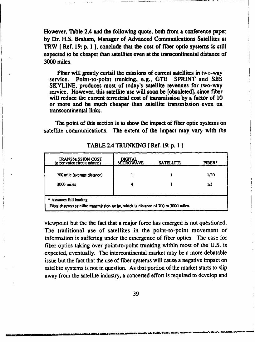
I. ~--- ----- ~n pt7Iaflln flfl Afll ~ ~ ' .f ~~ M ~
However, Table 2.4 and the following quote, both from a conference paperby Dr. H.S. Braham, Manager of Advanced Communications Satellites atTRW [ Ref. 19: p. I ], conclude that the cost of fiber optic systems is stillexpected to be cheaper than satellites even at the transcontinental distance of3000 miles.
Fiber will greatly curtail the missions of current satellites in two-wayservice. Point-to-point trunking, e.g., GTE SPRINT and SBSSKYLINE, produces most of today's satellite revenues for two-wayservice. However, this satellite use will soon be [obsoleted], since fiberwill reduce the current terrestrial cost of transmission by a factor of 10or more and be much cheaper than satellite transmission even ontranscontinental links.
The point of this section is to show the impact of fiber optic systems onsatellite communications. The extent of the impact may vary with the
* Assumes full loadingFiber destroys satellite transmission nrche, which is distance of 700 to 3000 miles.
viewpoint but the the fact that a major force has emerged is not questioned.The traditional use of satellites in the point-to-point movement ofinformation is suffering under the emergence of fiber optics. The case forfiber optics taking over point-to-point trunking within most of the U.S. isexpected, eventually. The intercontinental market may be a inore debatableissue but the fact that the use of fiber systems will cause a negative impact onsatellite systems is not in question. As that portion of the market starts to slipaway from the satellite industry, a concerted effort is required to develop and
39
- -% l ,
expand those areas in which satellites can be cost effective. Referring toFigure 2.11, it is apparent that there are several other areas in which asatellite's special capabilities may be used. The trends indicate that expectedgrowth is likely in all areas except point-to-point trunking. While the bentpipe satellite is becoming obsolete versus fiber optic systems, a new dynamicsatellite capability may open new markets for the communications satellite.Figure 2.11 projebcts a rapidly increasing trend for satellite point-to-pointcircuits with a capacity of up to a T-1 (designation for a circuit that has a1.5 Mbps data rate capability) data rate. The capability ot emerging satellitetechnology to take advantage of this opportunity is what the ACT S programis based on in order for satellites to regain some ground in a diminishingmarket with the emergence of fiber optic systems. It is hoped that the ACTS
program, discussed in the next chapter, with its state-of-the-art
communications technology will be competitive with the fiber optic systems.
40
III. COMMERCIAL SATELLITE COMMUNICATIONS--TOMORROW
A. SATELLITES RESPONDING TO CHANGEThe information discussed in Chapter II clearly shows that commercial
satellites are feeling the impact of fiber optics' emergence into themarketplace. The trends in satellite opportunities shown in Figure 2.11projects that point-to-point trunking, especially in the U.S., will be a failingmarket for satellites in the next decade. Other areas listed in Figure 2.11 arein many ways uniquely suited to satellites; hence, the expected trends in thoseareas ( mobile communications, video and computer broadcast, VSAT, etc.)are projected to continue rising. However, the communications satelliteindustry has not given up on the point-to-point market and is confident thatnew advances in communic'i ;ions satellite technology will re-establishsatellites as a force in the market.
A feature of any terrestrial network, be it optical fiber, cable, or radiosystems, is that its cost is based on a summation of the parts. This means thecost of using a circuit from end to end must take into account the costs of allthe cables, switches, and repeaters between the two locations. The bulk ofthese costs are encountered following the long distance transmission path asthe circuit moves down the different levels to the subscriber, commonlyknown as thefinal mile. Thefinal mile also includes those costs incurred atthe beginning of a circuit. These final mile costs may contribute as much asone-third of the total communications costs. If the costs for local exchangesand billing, engineering, and fixed plant are combined with the final milecowts, a figure as large as 60% of the total communications cost may result.This figure is independent of the distances involved. A NASA diagram,Figure 3.1, shows a pictorial representation of the current architecture forterrestrial switching, which highlights the idea of the final
* mile. [ Ref. 14: p. 2]Table 3.1 shows some typical costs for long haul business users. The
information was presented by Dr. H.S. Braham of TRW at Worldcom '85 in
41
Un --a •••E lWl'f•3-• •V''% '% 'b•k' 'L5 ' '% LI
TABLE 3.1 APPROXIMATE LONG HAUL COSTS FORBUSINESS USER [Ref. 21: p. 3]
q q %n qq q 'UIi
rn 90 ,
.~ t
.--.
o ..... •
42
October 1985. From the table, it is proposed that a major portion of the costsare attributable to categories other than tra.ismission of the signal. Dr.Brahain stated, in a telephone conversation on 20 May 1987, that he considersthose costs associated with the final mile to be equated to the term accesscharges in Table 3.1, although he prefers the usage of the term access chargesas more definitive. The term final mile, as described in the previousparagraph, will continued to be used in the following discussions.Thus, itwould seem that significant cost reductions could be made if those costsassociated with the final mile were eliminated or reduced regardless of thetransmission path.
r''•[" I"INLMLE "• RADIO RELAY PAX UE
SWITCHtES SWITCHES
uLO0CAL :TOLLr• .. ,, TOLL LC~
PABX = PRIVATE AULIOMATIC BRANCH EXCHANGE
Figure 3.1 Current Architecture Terrestrial Switching [Ref. 20]
The terrestrial communications systems have inherent problems withtheir ability to reduce or eliminate these final mile costs. A case in point isfiber optic communications. Fiber optic systems are most effectiveeconomically when filly loaded at high data rates. However, the competitiveedge for fiber optics starts to deteriorate as the data rate moves lower and isnot competitive at 1.544 Mbps and below. Figure 3.2 illustrates the problemof reaching the user and keeping the fiber optic system cost effective. Thecost of going from the very high capacity trunks to the local user representsthe high cost of the final mile for fiber optics. While all systems have somesort of hierarchy to traverse to get to the user, the capability of the satellitesystem to terminate at the user significantly reduces the levels of hierarchy.Terrestrial systems, on the other hand, normally has a more extensive
43
hierarchy to traverse thus it is conceivable that a higher cost may be theresult. [ Ref. 8: p. 2 ]
As previously discussed, satellites are being pushed to expand anddevelop new areas of commercial use as the use of fiber optics expands. Inthe drive for cost effectiveness, satellites, by their unique advantages andtechnology advancements, could offer an answer to reducing the final milecosts. The solution, as depicted in Figure 3.3, is to bypass much of theswitched network to get closer to the user.
Today, many corporations use a form of this bypass system by usingvery small aperture terminals (VSAT), located at the customer premises,passing information to a central node or hub via satellite. This provides thesecorporations with a cost effective method of collecting large amounts ofrandom data from large numbers (possibly thousands) of locations. Thesenetworks, because they bypass the terrestrial system and are cost effective,are growing rapidly [Ref. 14: p. 4 ]. Figure 3.4 highlights the key
SWITCH VERY HIGH CAPACITY 7si FIBER OPTIC TRUNK
DISTAN'r USERSHIGH
CAPACITY TRUNKS2 CANNOT CONNECT'
TO NEARBY HIGHCAPACITY TRUNK
MEDIUM CAPACITYTRUNK
S3UGHTF CAPACITY
TRUNK
S4 LDW SCAPACITYTRUNK
SI-S5 ARE SWITCH CENTERS
LOCAL USERS
Figure 3.2 Access to the Fiber Network [Ref. 8: p. 4]
factors of the VSAT service. Additionally, Table 3.2, presented by Dr.Braham at Worldcom '85, is a list of corporations that were using or
44
SATELJLITE•
QTERRESTRIAL
PUBLIC SWITCHED NETWORK
Figure 3.3 Satellite Bypass of Public Switched Network [Ref. 8: p. 3]
Non-ProcessingSSatellite L 0 • STAR configuration 4 C nr
(USA Covera e CentralMainly remote to central Hub
00 Primarily 2-way data Remote
• Under 10 Kbps average station rate.since large cost per spacecraft bps
S • P Access usually TDMA/TDM of100 Kbps/300 Kbps
P Station cost $6000 to $15000
1.2m or 1.2m or1.8m 1.8m
CENTRAL HUB -- ALL COMMUNICATIONS MUST GO THROUGH HUB(7m)
Figure 3.4 Very Small Aperture Terminal (VSAT) Customer PremiseService (CPS) [ Ref. 19: p. 2 1
45
planning to use a VSAT system. However, the VSAT system is not effectivein terms of voice traffic which still comprises approximately 85% of alltraffic. This limitation on voice traffic is a function of the delay due to thedouble hop communications. Double hop communications stems from thefact that all communications must pass through the central node, depicted inFigure 3.5. Another limitation is attributed to the amount of cost effectivethroughput possible. A non-processing satellite, i.e., bent pipe, cannotsupport the high data rate requirements desired by businesses on smallterminals and be cost effective. [ Ref. 19: pp. 3-4]
TABLE 3.2 VSAT CPS CIRCA 1985 [ Ref. 21: p. 6]CUSTOMER STATIONS - CONTRACTOR
Schlumberger >300 M/A COM
Walmart >800 M/A COM
Southland(7/1 1) >300 WA COM
Haliburton Many ASCICOMSAT Technology
K-Mart 2300 GTE SPACENET
Xerox Many Telecom General
Mutual Broadcasting About 1500 Unknown
P GM/EDS 25,000 TBDa Federal Express 50,000 Zapmai TBDnn Many others TBD TBDd (oil companies,IBM)sil Customer puts up capital or long-term lease (3 to 10 years)
The satellite communications industry believes that to take fulladvantage of the satellite's capabilities, a dynamic system incorporating thefeatures of terrestrial switching but bypassing a significant portion of thefinal mile hierarchy is the next logical and competitive step for satellitecommunications. In accordance with these beliefs, several countries have
initiated programs to develop those satellite capabilities required to makethem competitive with terrestrial technologies in the next decade. The three
46
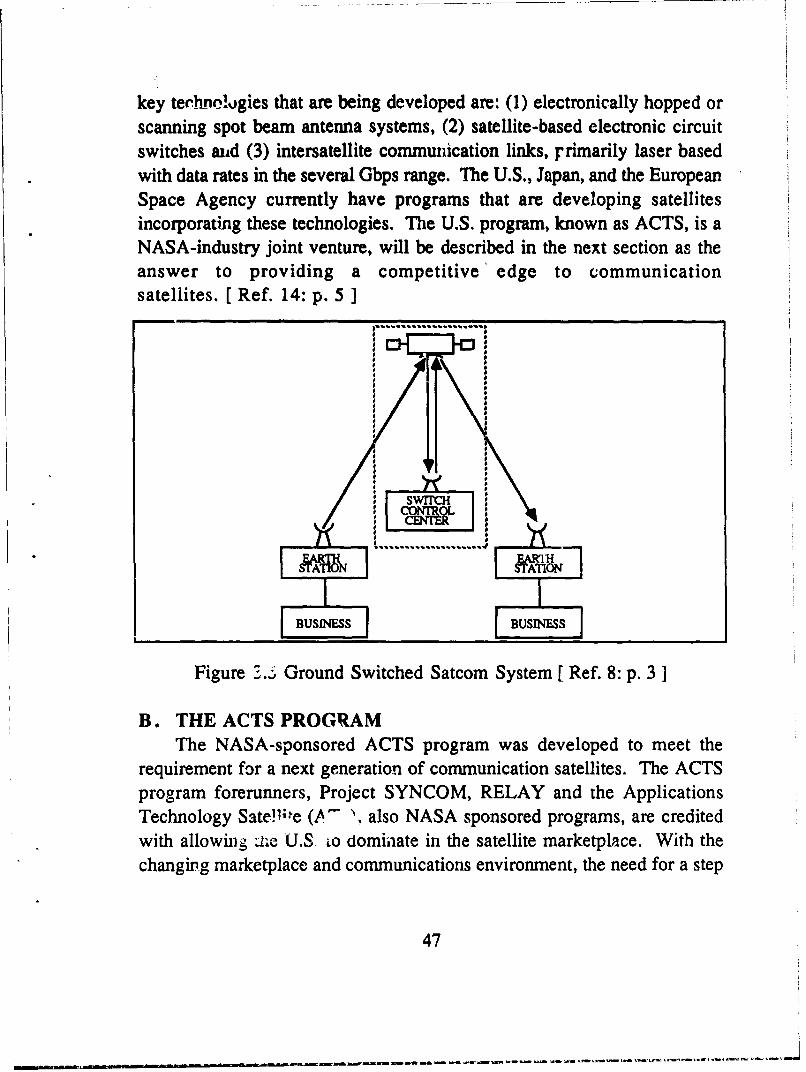
- 1.• P
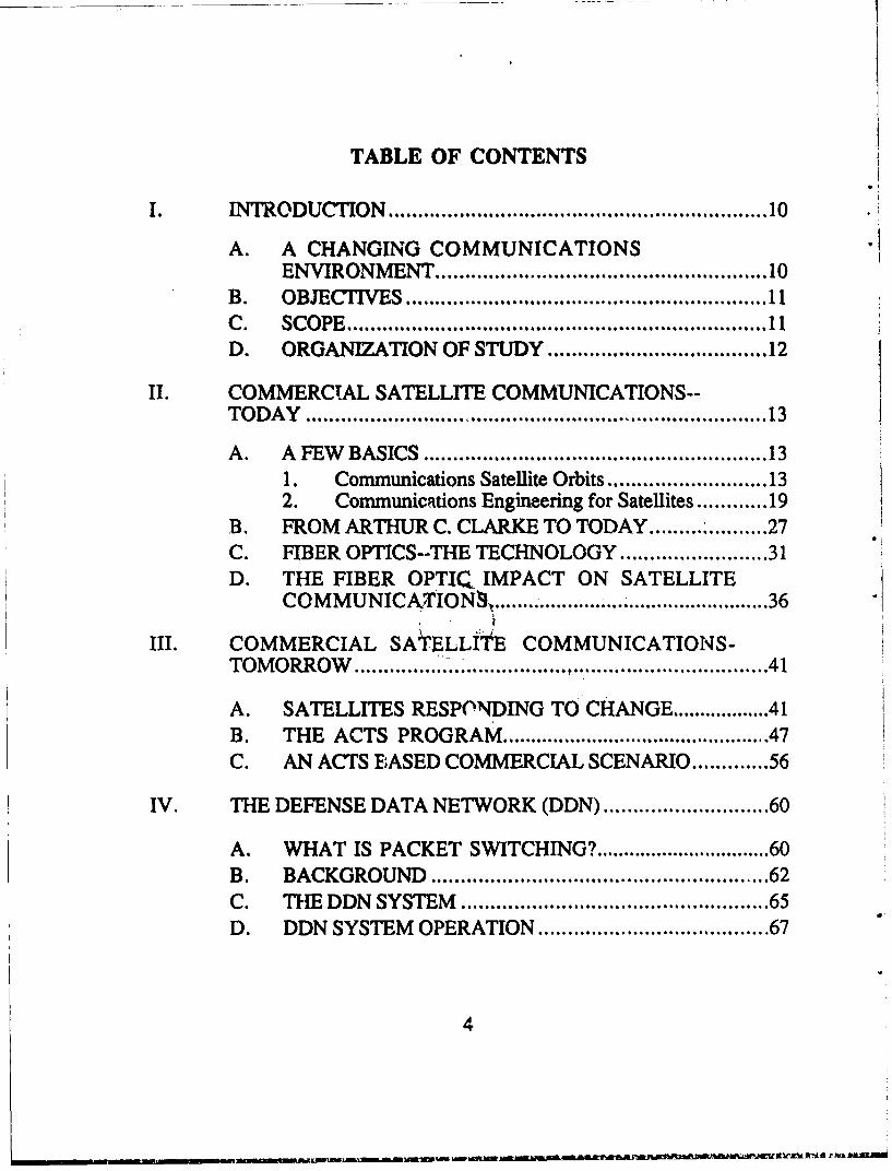
key technhoklgies that are being developed are: (1) electronically hopped orscanning spot beam antenna systems, (2) satellite-based electronic circuitswitches aud (3) intersatellite communmication links, rrimarily laser basedwith data rates in the several Gbps range. The U.S., Japan, and the EuropeanSpace Agency currently have programs that are developing satellitesincorporating these technologies. The U.S. program, known as ACTS, is aNASA-industry joint venture, will be described in the next section as theanswer to providing a competitive' edge to communicationsatellites. [Ref. 14: p. 5 1
8 .. ........------
LJ|
I I
Figure 3...; Ground Switched Satcom System [ Ref. 8: p. 3 ]
B. THE ACTS PROGRAMThe NASA-sponsored ACTS program was developed to meet the
requirement for a next generation of communication satellites. The ACTSprogram forerunners, Project SYNCOM, RELAY and the ApplicationsTechnology Sate~l;e (A"- •, also NASA sponsored programs, are creditedwith allowing ii~e U.S io dominaate in the satellite marketplace. With thechanging marketplace and communications environment, the need for a step
47
n !e ab- fl --t.'
into the next generation of satellites is at its most criticalpoint. [ Ref. 22: p. 31
A primary reason for the involvement of NASA in the SYNCOM,RELAY and ATS programs was that those programs represented the leadingedge of the emerging field of satellite communications. As a result, thesehigh technology programs were a high risk, high cost venture. Theinvolvement of NASA provided government funding of these pro~grams sothat the risk assumed by industry was within their means. The result was thecurrent dominance of U.S. satellite manufacturers. [ Ref. 22: p. 5
From NASA's and industry's point of view, the same situation nowpresents itself for the next step in satellite development. Although thesatellite industry is well established, the development of a program to makethat quantum leap is a significant demand on industry resources. NASAstipulates that the three main reasons that limit industry expenditures andnecessitate government funding are the large investment necessary, a longtime until payoff, and the high risk factor associated with the program. Theexpected annual expenditures for the ACTS program over the next few yearsis $100 million. However, a reasonable range for a major satellitemanufacturer to spend in advanced satellite development is only $1 0-20million. Due to the experimental nature of the ACTS program, a return onthe investment may not be seen for as long as 10 years. This long delay in areturn on investment severely limits the U.S. manufacturer's ability to
participate. Finally, the last element is the high risk associated with theI program. The technology involved in the program is on the leading edge;therefore, delays, deficiencies in performance, or system on-orbit problemsmay cause unacceptable risks in terms c. the company's future. Thecombination of these three factors necessitated the need for governmentsponsorship to offset the drawbacks of the program and encourage industryinvolvement. The government sponsored agencies of Japan and the ESA are
developing programs along the same lines as ACTS. [ Ref. 22: p. 5 ]
The ACTS program is a proof of concept application ofN state-of-the-art technology for communications satellites. The purpose of
the program is to put ground-tested new technologies in the environment ofan actual flight system. The ACTS satellite will be launched from the Space
48
Shuttle in the 1989-90 time frame. The scheduled duration of theexperimental program is two years. The ACTS program satellite will be ascaled down version of futw'ev satellites that will use the same technology.
The following extract from NASA'S ACTS: Notice of Intent forExperiments [ Ref. 23 ] outlines the experimental program:
The National Aeronautics and Space Administration (NASA) isconducting an Advanced Communications Technology Satellite (ACTS)Program to advance the high risk technology required to ensurecontinued United States' preeminence in the field of satellitecommunications. The objectives of the ACTS Program are to developand validate the technology required to enable growth in the capacity andeffective utilization of the frequency spectrum and to effect new andinnovative uses for satellite communications.
A primary goal of the ACTS Program is to make available to the publicand private sectors (corporations, universities and government agencies)the capabilities of the ACTS spacecraft for experimentation. At thistime, it is the intent of NASA to consider all experiments technically andscientifically relevant to the basic objectives of the. ACTS Program andfor which the ACTS System can accommodate. NASA will develop h.1eflight system and provide access to the ACTS space segment at no cost tothe experimenter. Each experimenter will be responsible for the conductand funding of their experiment. [ Ref. 23: p. 1]
In the following paragraphs, the ACTS will be descr' 'd in a basicfunctional manner. No attempt will be made to provide an engineering leveldegree of detail, rather a simple description of the satellite and how itoperates will be provided.
The ACTS program involves the testing and evaluation of many highlycomplex technologies. The complex nature of these technologies is beyondthe scope of this effort. For the interested reader a list of the proof ofconcept technologies is shown in the Appendix. For this effort the basicdescription of the satellite and four critical technologies will be addressed toprovide a basis for further discussions. The four technologies that will bediscussed in relation to ACTS are the electronically hopped spot beamr, theonboard baseband processor, customer premises satellite (CPS) terminals,
49
and laser intersatellite communications iinks. Several general aspects of theACTS system will be brief discussed before examining the four specificareas.
The satellite will be launched from the shuttle in low earth orbit (LEO)and moved to its permanent geosynchronous orbit at 1000 West Longitudewith the apogee kick motor (AKM). The satellite uses solar power and isthree-axis stabilized. Three-axis stabilization means that the properorientation of the spacecraft in space is maintained by various combinationsof momentum wheeks, reaction wheels, and thrusters [ Ref. 7: p. 130].Satellite tracking, telemetry, and control functions will be performed by theMaster Ground Station (MGS) located near Cleveland, Ohio at the NASALewis Research Center. The control station also controls the ACTScommunication system. Ground terminals communicate with the MGS via aseparate communications engineering circuit commonly known as anorderwire. The terminals request or release 64 Kbps channels based on theirrequirements. As these requests come in, the MGS changes the programmingin the baseband processor to accommodate the requirements.Synchronization and dynamic processing are critical elements of the ACTSsystem. The MGS communicates with both the satellite and the experimenterterminals to control system synchronization and demand accessrequirements. Additional information on the ACTS is provided inTable 3.3. [ Ref. 24: pp. 197, 200 ]
TABLE 3.3 ACTS GENERAL INFORMATION[ Refs. 25: p. 4, 26: p. 8 1
WEIGHT: 2843 LB. ON ORBITPOWER: REQUIREMENT: 1770 WATTS
SOURCE: 4 SOLAR ARRAY PANELS (140 SQ FT TOTAL AREA)DESIGN LIFE: 2 YEARS (POSSIBLE 4 YEAR MISSION LIFE)FREQUENCY RANGE: UPLINK: 27.5-30 GHz
The ACTS communications system has two basic operational modes:high burst rate (HBR) and low burst rate (LBR). The HBR mode works withthree fixed-spot beams at a data rate of 220 Mbps per beam. The purpose of
50
.. aafa-.aSC.AJln..JA.nalt-•J'a.mLln:aan t , .SIILI ' -I'II ."IIV•a.JSfl h]S " S1 J S hAS -' It 5~' ••I~k 5 .. J mLS. 6• - 66 6 , '. • .
the HBR mode is to provide major trunking services for largecommunications users. Dr. H.S. Braham, in an interview onJanuary 14, 1987 (Ref. 27 ], indicated that he did not believe that theHBR mode would be justified for the operational ACTS because it could notcompete with fiber optic systems. Dr. Braham had previously stated thisviewpoint in his paper, Improved Satellite Cost and Performance UsingACTS Multi-beam Processing Satellites presented at the AIAACommunication Satellite System Conference, San Diego, CA on March 18,1986 [ Ref. 19 ]. The validity of this position may be justified by furtheranalysis but mat is not within the scope of this effort. Therefore, furtherstudy of the HBR mode will not be made within the context of this thesis.Instead the thesis will concentrate on aspects of the LBR mode. The LBRmode incorporates the use of independent scanning, or electronically hopped,spot beams with the onboard baseband processor and small earth stations.The primary purpose of the LBR mode is to provide business users access toa dynamic, flexible system via small, cost effective earth stations. The abilityof the system to fulfill this purpose is part of the experimental program. Theindividual satellite channels in the LBR system have a 64 Kbps data rate.The system operates at a maximum rate of 110 Mbps per beam of which anyinteger multiple of the 64 Kbps channels can be transmitted in a single burst.In this case, there are 1728 channels available within the 110 Mbps data rate.The laser intersatellite link, although not directly a part of the LBR system,will be discussed for its role as a link to other satellites in a network. Thefollowing paragraphs discuss the four highlightedtechnologies. [ Ref. 28: pp. 188-192]
A critical portion of the LBR system is the scanning spot beams. TheACTS experimental system, as shown in Figure 3.6, has two pairs of thesescanning beams, each beam pair assigned a specific section of the U.S. Asimplified discussion of how the scanning beam works is given in the nextparagraph.
As stated in Chapter H, a general rule of thumb for antenna beams is thatthe narrower the beam the higher the effective gain of the antenna system.The ACTS scanning beams have beam widths of 0.40. This is smaller than theexamples shown in Table 2.2, and corresponds to an approximate coverage
area diameter of 175 miles. The greater gain created by the narrower beammeans that a terminal station within the footprint of the antenna can use asmaller antenna surface to operate within the system. By using the antennahardware on the satellite, different antenna beams are turned on and off in apredefined order, thereby illuminating different areas on the earth with eachbeam. This series of footprints establishes a coverage area for theappropriate scanning beam and represents the apparent hopping of the beam.For the ACTS, each scanning beam covers an area approximately equal to10% of the area of the U.S. Therefore, with the two beams on the ACTSexperimental satellite, the coverage area is approximately 20%, as outlinedon Figure 3.6. [Refs. 19: p. 1; 24: pp. 199-200 ]
• Multivle T-1 for voice, data,teleconferencing, %
•0 Spacecraft baseband procemor 0 SBlr
,.Satellite switching like 4E:SS vA
Figure 3.6 ACTS 30/20 GHz Experimental System (CPS Mode)[ Ref. 19: p. 2 ]
Each scanning beam will normally move to 10 different locations withinits coverage area in a cycle. This cycle represents one frame in the TDMAscheme. This cycle, or frame, is one millisecond in length with the scanningbeam able to move from one location, or dwell area, to another in one
52
microsecond. The remainder of the time in the cycle is used in receiving ortransmitting information. This is the use of the TDMA structure previouslyexplained in Chapter II. For ACTS, the downlink signal is pure TDMA,however for the uplink signal it may be a combination of FDMA and TDMA.As previously stated, the LBR system operates at a maximum data rate of110 Mbps per beam or it may be segmented into four 27.5 Mbps channels.This is possible by using FDMA within the TDMA scheme of the scanningbeams. In other words, each of the four 27.5 Mbps channels is operating atdifferent frequencies (FDMA) within the same spectrum of the one110 Mbps channel. This will significantly increase the number of users whohave access to the satellite. Figure 3.7 shows the uplink beam FDM/TDMorganization. The message bursts shown in Figure 3.7 are a function of the
user traffic demands. These bursts may vary from one slot within the dwellperiod up to the entire frame time of one millisecond. Each of the messageburst lengths is adjusted according to the user's requirements. Thisassignment of burst time based on need is referred to as demand assignedmultiple access (DAMA). Therefore, as the scanning beam moves from areato area, the users in each area transmit their traffic in short bursts as a time
53
--------------- ~---~-~-~------
share user. They are using the same frequency as other users in their area buta different slot in time to prevent interference. The FDMA users are usingthose same time slots as other users but at different frequencies. In additionto the increase in the number of users possible, the FDMAfTDMA requireslower TDMA burst rates which benefits the use of lower power smallterminal transmitters. [ Refs. 24: p. 200; 29: p. 673 ]
Working in conjunction with the scanning beams is the heart of theACTS system, the onboard baseband processor. The processor for the ACTSis being built by Motorola Inc. and can be compared to the current electroniccircuit switch that is used by AT&T, i.e., a 4ESS switch, in their terrestrialsystems. The 4ESS switch is the backbone toll switch in that network. Thismeans that the processor will take the uplink signal burst from the groundterminal, break it down into individual message elements by theirdestination, store the information, and then at the appropriate moment sendthe elements to the correct downlink path. The baseband term refers to thebreak down of the signal to the individual circuit level so switching mayoccur. The routing switch in the baseband processor is an 8x8 high speednonblocking switch which, for the purposes of the ACTS experimentalprogram, iF connected as a 3x3 switch. Nonblocking means that there is apath out for every path in, therefore no block of traffic can occur. The datatraffic passes through any of the three input ports to the outlet ports at a rateof 110 Mbps. The maximum rate permissible through the switch is220 Mbps, a system requirement not a switchlimitation. [ Ref. 29: p. 674; 19: p. 2]
The third key element in the effective use of the LBR mode is the groundterminal. A critical factor in the success of the ACTS application is theability to put small low cost, high data rate, ground terminals directly on thecustomers' premises. As discussed before, the gains of the narrow scanningbeam permit the use of smaller ground terminals to achieve high data rates.This makes possible the use of these terminals at a variety of locationsthereby forming a network of proliferated ground stations that bypasses thelocal terrestrial network. Table 3.4 shows the three basic ground terminalsfor ACTS in the LBR mode.
54
The fourth critical technology that the ACTS program will incorporateis that of intersatellite laser links. The laser links will be evaluated to supportthe concept of dynamic data transfer between satellites based on trafficdestination requirements. The future goal is for distributed switching amongsatellites much as it is done in terrestrial systems. The distributed switchingwould cause minimal delay and avoid the relatively lengthy delays of doublehopping between ground connected satellites, as illustrated in Figure 3.7.Two Gbps data rates are possible between satellites with the current lasercomponents that are sized for satellites [ Ref. 14: p. 5 ].
SATELLITE TYPE ANTENNA CAPACITY UPLINK/DOWNLINK ACCESSROUT'ING MODE DIAMETER BURST RATE
(METER) MBPS
MICRO-I 1.8 1 TO 24 EVC 27.5/110 TDMA
BASEBANDPROCESSOR VIA LBR-2 3.0 1 TO 48 EVC 55/220 TDMATWO HOPPING
BEAMS
LBR-1 5.0 1 TO 96 EVC 110/220 TDMA
EVC- 64 KBPS EQUIVALENT VOICE CIRCUIT
To explore this concept on the ACTS, a laser link will be tested asdepicted in Figure 3.8. Although geosynchronous earth orbit (GEO) to GEOlaser interconnects will not be tested, the GEO/LEO links with the Shuttlewill provide information for evaluation of system performance. The testswill also provide information for future LEO/LEO links as well as linksfrom the future Space Station to other orbiting platforms. Data from theshuttle sent by laser can be returned to the shuttle by laser or sent to groundby the radio frequency (RF) or laser downlinks. Data from the ground willgo to ACTS via the RF link and to the shuttle by laser. The laser will be a220 Mbps duplex laser. Duplex means that traffic may be passed both ways
55
simultaneously. The data rate from ACTS to the shuttle will be 50 Mbps but220 Mbps on the return link. [Ref. 8: p. 13]
The previous paragraphs in this section have discussed the ACTSsatellite and four key technologies in a much simplified manner. A greatlydetailed look at the many complex systems which comprise the ACTSprogram is beyond the scope of this thesis. Those areas discussed are key tothe ACTS concept and further discussion within this document. As"previously noted, more detailed information on the ACTS may be found inthe Appendix and the references. The next section will present a briefscenario of the ACTS concept applied in the commercial environment.
ACTSOPTICAL.I •"]--"
SHUrrLE OPTICAL
.'=• / 120 GHzLAE RF DOWNLINK
Figure 3.8 The ACTS Optical Intersatellite Links [Ref. 8: p. 13]
C. AN ACTS BASED COMMERCIAL SCENARIOThe next few paragraphs will briefly look at the application of the ACTS
concept in a commercial based scenario. The intent will be to show how thetechnologies highlighted in the previous section may be applied in a businessapplication. The basis for this discussion will be Dr. Braham's paper,
56
Improved System Cost and Performance Using ACTS Multi-beamProcessing Satellites [ Ref. 19 ]. Dr. Braham's paper discussed anOperational ACTS (OACTS) system as opposed to the experimental ACTSsystem previously described. An Operational ACTS (OACTS) system willbe assumed within the context of this discussion with the greatest differencebeing the scaled up capability of an operational satellite. Any other assumeddifferences between what was previously described and the OACTS systemwill be noted as they occur. An in-depth detailed discussion will not bepresented here but rather an illustration of the concept.
As previously mentioned, the VSAT concept of many remote stationsexchanging traffic with a central node has been gaining acceptance amongmany large corporations. However, the concept falls short of optimizing thecommunications possibilities for voice circuits, low cost terminals, or highspeed data rate. The OACTS addresses these issues and ushers in acompetitive satellite environment. The 4ESS switch was also previouslydescribed as AT&T's primary switch for its backbone terrestrial network.The 4ESS will be used here as a basis of comparison to the OACTS.
The OACTS system would probably employ several thousandtransmit/receive stations in a full up system. However, for the purpose ofthis scenario, 1024 stations will be assumed to parallel the capacity of the4ESS. A block diagram of the OACTS is shown at Figure 3.9. These 1024stations are small (1.8 meter antenna) earth terminals capable of T- 1 datarate for voice, video conferences, and high speed data. They are spreadacross the U.S. covered by the 100 OACTS spot beams required to coverthat area [ Ref. 19: p. 2].
Corporations A and B have 200 stations each that are located throughoutthe U.S. They each have information to pass among any of their respectivecorporation's stations or to any of the other corporation's stations. Each ofthe stations can transmit information to multiple receive stations at the sametime. For instance, a station of Corporation A may be transmitting a numberof voice conversations, each routed to a different receive station. Thesatellite stores the received information after scanning all 1024 stations. Theinformation is broken down by the baseband processor then collected into apacket of information for a particular station. Therefore, if Corporation A
57
stations in California and New Mexico are sending traffic to a Corporation Bstation in New York, the information is collected in the packet destined forthat terminal. If the Corporation B station is not the only station in that spotbeam getting traffic, each station is transmitted to sequentially in the assignedTDMA format. The spot beam is then moved to the next area and packets aretransmitted as required to the receiving stations. This downlink process iscontinued through the 1024 stations until all previously received and stored
....................................................MULTIPLE i UPNK DOWNLINK DOWN MULTIPLEACCESS UPLINK I SCANNING SCANNING• LINK ACCESSWITHIN 0.40 I BEAM BASEBAND BEAM i 0.40 WTITEN
STNS spOr SPOTS . SWITCH PROCESSOR SWITCH ISOS SPOT SNSFDMA/FDMAJREGION RrOGION / 1TDMA " 1D l RPS
*ACTrS IMPLEMENTATION: 2 OR 4 SCANNING BEAMS, SOME OF 100 SPOTS,ONLY TDM ON DOWNLINK
Figure 3.9 System Functional Block Diagram (Operational ACTS)*[ Ref. 19: p. 3 ]
data is transmitted. The receive/transmit process is repeated making the1024 stations fully interconnected among all users. The switching operation
58
described for the OACTS is similar to the 4ESS switch. Figure 3.10 showsthe functional block diagram for the 4ESS. Each input/output line (read asstation for OACTS) has 105 different TDMA channels (read as TDMA slotsfor OACTS) which can be routed to any other channel. The OACTS worksas a switchboard in the sky. [ Ref. 19: pp. 2-3]
LINE 1 • 105 TDMA CH* 0 D& LINE I
4ESS SWITCH15MCH(EQUIVALENT 105 TDMA CH LNLINE 2 TO ALINECT
INPUT BASEBAND(EACH EQUAL PROCESSOR OUHUTQLINFS
TO AN ACTS AND (EACHEQUALTRNSr SCANNING "TO AN ACTS
TRANSMTBEAMS) RECEIVE STATION)STATION) LINE i LINE j
LINE 1024 105 TDMA CH 105 TDMA CH LINE 1024
*COMPRISED OF 5 T-1 (24 CHANNELS PER T-1, LESS OVERHEAD)
pp ANY OF THE 105 INPUT CHANNELS OF LINE i (OR ACTS TRANSMIT STATION A) CAN BEROUTED TO ANY OUTPUTJ (OR ACTS RECEIVE STATION B)
Pp EACH OF THE 105 OUTPUT CHANNELS OF LINE j (OR ACTS RECEIVE STATION B) CANORIGINATE FROM ANY INPUT LINE (OR ACTS TRANSbi f STATION)
Figure 3.10 4ESS (and Equivalent in ACTS) [ Ref. 19: p. 4]
This chapter has examined the ACTS program, highlighting several keytechnologies and discussing a brief scenario on its use. As previouslydiscussed, the intent is to provide a look at capabilities and not get involved ingreat detail. Up to this point, it is hoped the reader has attained a basicunderstanding of satellite communications, the present state of the satellitecommunications industry and the role that ACTS may play in revitalizing thesatellite industry. The next chapter will examine a specific governmentcommunications network, the Defense Data Network (DDN), its futureevolution into a comprehensive worldwide data network, and the possiblerole that ACTS could play in its future.
59
IV. THE DEFENSE DATA NETWORK (DDN)
This chapter will provide basic information on the DDN to includebackground information, an overview of the DDN technology and a brieflook at the operational concept for the DDN. As with previous chapters ofthis thesis, a detailed discussion of the technology compon~ents andprocedures will not be attempted here. The discussion will involve generalconcepts and operational information. The object will be to provide basicinformation that may be combined with information presented in previouschapters for further discussion. Prior to discussing the DDN, a briefdiscussion of packet switching, on which the DDN is based, will be provided.
A. WHAT IS PACKET SWITCHING?Packet switching is based on the concept that a length of information bits
representing a message can be comprised of many small packets ofinformation bits. Figure 4.1 is used as an illustration. A message is enteredinto the system from a user or a computer host, in this case called the sourcecomputer. The message goes from the source computer to the packet switch.At the switch the message is stored temporarily until the switch is prepared totransmit. While processing the message, the switch divides the message intopackets of bits, each packet the same size. The size of the packets may varyfrom network to network. The DDN uses packets of 1008 bits. The packetsare themselves individual messages with the required information to get themto their destination switch. The switch determines the proper routing for thepackets and sends them to the proper switches. Each packet sent betweenswitches is acknowledged (ACK) by the receiving switch. In the diagram thetandem switch refers to the relay function of the switch in passing thepackets. At the destination switch the packets are reassembled into theorighinal message and forwarded to the destination computer. The destinationswitch acknowledges the receipt of the message by sending an ACK back tothe source computer. The ACK takes the f'orm of a request for next message(RFNM) as the system operates on the assumption that another message will
60
technique, however, significantly increases the amount of traffic on thenetwork, and as the network size increases so does the traffic load. Thistechnique provides a very robust system and is used in some militaryapplications. Procedures for decreasing the load on the system while usingthis technique have been devised. [ Ref. 32: pp. 180-1811
Directory routing is the most frequently used of the three techniques.The directory technique uses a table, or set of instructions, that tell the switchwhere to transmit incoming traffic. The directory may have knowledge onlyof switches immediately adjacent to it, or its knowledge may encompass thewhole network. These are known as partial-path or full-path directories,respectively. The full-path directory enables the switch to determine theshortest path to the destination based on its current knowledge of thenetwork. The most flexible of the techniques within this category is adaptiveJor dynamic directory routing. The switches are continually updated on thestatus of the system and can select the shortest path to a packet's destinationfor each packet that enters the switch for transmission. The DDN uses thistype of routing technique. [ Ref. 32: pp. 180-181, 185-186]
B. BACKGROUNDThe evolution of the DDN first started in 1969 as a research and
development project managed by the Department of the Defense (DoD). Theprogram was directed by DoD's Advanced Research Projects Agency(ARPA), now known as the Defense Advanced Research Projects Agency(DARPA), and was the forerunner of present day packet switching networks(civilian or military). The network was labeled the ARPANET. TheARPANET was originally devised as a network with an experimentalpurpose. The network connected a wide variety of us'-rs, primarily acrossthe U.S., with its princIpal role being that of a de'velopment tool forstate-of-the-art advances in computer resource sharing. The networkprovided the sharing of hardware, software, and data resources through theefficient use of computer communications across a broad range of users. Asthe experimental nature of the network progressed, it also became a much7
K used, effective system for those customers with operational requirements.Because of the increased use of the network by operational users, the
62
.a ~ ~* * * an * = aa a. ~ n , ,.I ~ eJt~J-. i *9 N. d I A A A A IAI "42 W 41a UM. S
responsibility for system operation was transferred from DARPA to theDefense Communications Agency (DCA) in 1975. [ Ref. 33: p. 2]
In late 1981 the Director of the DCA tasked a design team to examine thepossibility of developing an ARPANET-based system as a replacement forthe AUTODIN II system. AUTODIN II was the second phase of theAutomatic Digital Information Network (AUTODIN). AUTODIN providesthe capability for the U.S. government to pass message traffic worldwide.AUTODIN is a message switching network, as opposed to packet switching,therefore each message is stored in its entirety before being passed to the nextswitch. This method of handling the data constitutes a basic difference fromthe ARPANET and was a key point on which the study focused. As a resultof the study, Deputy Secretary of Defense Frank Carlucci, on 2 April 1982,directed that the DDN be developed as a replacement to the AUTODIN IIprogram. The AUTODIN II program was terminated with the issuance ofMr. Carlucci's directive and the DDN began its evolution into the primarydata system for the DoD. The initial plan reflecting the development of theDDN was the Defense Data Network Program Plan published in January1982 and revised in May of that same year.[ Refs. 31: p. 29; 34: pp. iii-v ]
The ARPANET was initially divided logically in 1983 and thenphysically in 1984 into the ARPANET and the MILNET (Military Network).This represented the two basic users of the network with the ARPANETremaining essentially a research and development network and the MILNETan unclassified operational military network. Figure 4.2 depicts the eventualevolution of current or planned data networks into the DDN. Thedevelopment of the classified segment of the DDN will result from the use ofend-to-end secure devices that will allow higher classification level trafficto ride the secret backbone. The interconnection of the networks willprovide more capability for the classified segment and will be controlled byone-way gates to prevent a possible comprise of classified material.Eventually, the fielding of National Security Agency (NSA) communicationssecurity equipment, known as BLACKER, will allow for a single fullyintegrated multilevel secure network. [Refs. 33: pp. 2-3; 35: p. 2-3 ]
63
The single packet-switching network envisioned in the 1982 DDNProgram Plan was comprised of 171 packet switches spread over 85geographical locations and serving 488 hosts and 1446 terminals. Hosts arethose computers that use a packet switching network to communicate.However, the DDN in 1982 included three different segments, the
SSEEGMENT
AR T, tE ad theW t NT
requirement an unlssfe Do eurmns h IE a
WWsmCCS Infonr th W ideMwtrk Communications Suasnstem ( =Co S m
Figure 4.2 The DDN Evolution Strategy [ Ref. 33: p. 3]
ARPANET, the MINET in 198 INto the ARPANET AnANET wasmade up of approximately 100 packet switches and served researchrequirements and unclassified DoD requirements. The MINET was alogistics network for Europe, consisting of 12 packets switches and was beinginstalled in 1982. The WIN, the only part of the DDN which handledclassified traffic, was comprised of 17 packet switches and was the datasystem for the World Wide Military Command and Control System. Thesplit of the ARPANET in 1984 into the ARPANET and MILNETapportioned the switches 40 and 57 respectively. As previously mentioned,
the MILNET absorbed the MINET, also in 1984, and by October 1985 had
64
grown to 100 packet switches worldwide supporting 300 operational usersand moving over 14 million packets per day. [ Ref. 36: pp. 9-10 1
Upgrades to the various networks in Figure 4.2 are projected with theMILNET expanding to an estimated 174 switches connected by more than300 trunks. Further expansion of the MILNET is planned with an increase ofpacket switches in Europe to 44 by the end of 1987. The expansion of theclassified systems in Figure 4.2 is also proceeding toward the unified systembut will not be further described here. [ Ref. 36: p. 16 1
C. THE DDN SYSTEMAs a basis for further examining the DDN network, it is necessary to
understand the major components that comprise the system. Figure 4.3shows the components of the DDN system. In the following paragraphs, abrief description of the components will be stated to farther faniliarize thereader with the system operation.
HOST
HOST nt.E. Gateway... _... ... .. N tw r
Figure 4.3 DDN Components [Ref. 33: p. 7]
The backbone of the network are the packet switches. The packet switchcurrently used on the DDN is the C/30E packet switch manufactured by theBBN Communications Company. A fully compatible upgrade to the C/30E,the C/300, is being developed which will have double the capacity of theC/30E. The C/30 was the packet switch being used on the ARPANET when
65
the DDN was organized. Therefore, changes to the switch for use on theDDN were minor. The C/30E or C/300 are normally connected to threeother packet switches in the network. [ Refs. 36: p. 46; 34: p. 3 ] Thecapability of the packet switches is largeiy determined by the operatingsystem software of the switch. As an illustration, the user traffic ratecapacity of a full subnetwork (256 switches), of which the DDN is made up offive, increases from 5.9 Mbps to 10.2 Mbps with the change in operatingsystem software from Packet Switching Node (PSN) Release 6 toRelease 7 [ Ref. 36: pp. 43, 46 1. This is without hardwareimprovements. The C/30E can support up to 38 devices and the C/300 willbe able to support approximately 58 devices. This capability assumes thateach switch is also linked to three other switches. [ Ref. 36: pp. 4-5, 46]
Another important component of the DDN system is the host. The hostis linked to the network through the host interface device (HID). In Figure4.4 the three interfacing options for the hosts are highlighted. The direct link
HOST • : Monitor
:,HOST
HOST , n G1ý,ateway Netor
• -- •-TA( IPL HOST
Figure 4.4 Interfacing Options for the Host [Ref. 33: p. 7 ]
from host to switch (highlighted) indicates the use of the HID as the hardwareinterface with the host providing all the required protocols for operation.The Host Front End Processor (HFEP) option uses a front end processor withthe host computer. The front end processor runs the protocol software for
66
i i2L- - - -- -,-**-------------------
network operation instead of the host as above. The third option, theTerminal Emulation Processor (TEP), attaches to the terminal ports of a hostand also to a switch. In this configuration, the host can only see the networkas locally attached terrnials and not use the full capability of the system.This approach is not recommended except for special circumstances. Thehost may be colocated with the switch or linked by a communications circuitfrom a remote location. [ Ref. 34: pp. 48-58 ]
The Monitoring Center (MC) from Figure 4.3 is a computer providingthe system overwatch for a portion of the network. The MC continuouslymonitors information provided by network components to assess the systemstatus, topology, and throughput, as well as other information. The MC also
controls the system by being able to access components and make changes inconfiguration, isolate faults and diagnose problem areas, and performsoftware maintenance. The MC also acts as a database management facilityfor the network. [ Ref. 34: pp. 59-60 ]
The Internet Private Line Interface, (IPLI), shown in Figure 4.3, is asecurity device. The device consists of three components, two packetprocessors on either side of a cryptographic device. The IPLI allows theinterface of those hosts requiring protected systems into the mainstreamsystem. [ Ref. 34: pp. 39-40 ]
The Terminal Access Controller (TAC) and the min-TAC are interfacedevices that allows for the interface of a terminal with the network. The onlydifference is in the terminal number capacity, for instance, the mini-TACcapacity is 16 terminals, while the TAC's capacity is 63 terminals. Allterminals entering from a TAC or mini-TAC are multiplexed onto the samecommunications circuit that links the TAC to the switching node. Terminaldata rates supported by the TACs are from 110 to 9600 bps for direct linehookup or if dialing up, rates are from 110 to 2400 bps. On the other side ofthe TAC to the switch, possible transmission rates are from 9600 to56000 bps [ Refs. 34: pp. 42-43; 24: p. 4]
D. DDN SYSTEM OPERATIONAfter the preceding brief discussion of the components of the DDN
system, Figure 4.5 is shown to discuss DDN system operation. As previously
67
discussed, the DDN is segmented into two basic categories of classified andunclassified users. Figure 4.5 shows a block diagram of these two segmentsand how they interface. DES and KG, from the figure, represent encryptiondevices. DES (Data Encryption Standard) corresponds to commercialencryption techniques and is used on all interswitch trunks in CONUS for theunclassified network. KG (Key Generation) designates those devices thatare military grade encryption certified and are used for encryption on theclassified network and on all trunks leaving or external to the continentalUnited States (CONUS) regardless of the network. The protection of trafficwithin the DDN is provided by link encryption and end-to-end encryption.Link encryption provides the basic security level protection across the whole
CLASSIFIED SEGMENT UNCLASSIFIED SEGMENT
Monitoring MoiorCenter Cne'
Figure 4.5 Segmented DDN [ Ref. 33: p. 7 ]
system. End-to-end encryption provides for additiokial security bynormally encrypting particular circuits at a higher level of classification.
The gateways depicted on the diagram will allow the usage of the largeunclassified netlassified assified users, but not vice versa, if the situafionrequires it. [ Ref. 33: pp. 7-8 ]
68
U'
The performance of the DDN is measured by its ability to meet the needsof the users who require data services. The transmission time, systemavailability, and survivability are key factors of performance that are part ofthe DDN operation. The subdivision of the inputted data into packets,switching the data through the network, and the assembly of the packets forthe data do not present a major increase in the service time. This timeaccounts for a small portion of the waiting time experienced by an interactiveuser. Those interactive systems connected to the DDN are expected toexperience an increase of only about 200 milliseconds in response time fromthat experienced with systems connected by dedicated, long haul circuits.[ Ref. 33: p. 5 1
The average end-to-end delay for transmission of a high priority packetacross the DDN backbone is about 90 milliseconds, with 99 percent ofall packets being transmitted within approximately one-half second.Using transoceanic satellite circuits increases these figures by about300 milliseconds. Thus, DDN effectively supports query/response andinteractive applications as well as batch or record transmissions.[ Ref. 33: p. 5 1
The availability of the system for network users is one success measureof system operation. The DDN is designed so that at least 99% of the time asingle-homed user (user having access to one switch) will have access to thenetwork when it is desired. To further increase this percentage, users may bedual-homed from separate switches and their availability rate will increaseto 99.9%. This level of availability is critical to the successful operation ofthe network. The preceding three paragraphs provided information tofamiliarize the reader with the expected capabilities of the system.Variations may be experienced based on system maturity and/or traffic load.[ Ref. 33: p. 6 ]
Survivability of the DDN is of paramount importance due to criticalityof communications networks that comprise the DDN. A major survivabilityfeature is the robustness of the system in terms of number of nodes andtrunks. Additionally, the packet switching concept itself increasessurvivability through its use of adaptive routing and multiple paths. It also
69
incorporates three additional features to enhance the survivability of thenetwork. These features are network equipment facilities that are assurvivable as the user's facilities they are supiporting, a redundancy of criticalequipment and circuits, and a graceful degradation of service if systemdamage is sustained. Graceful degradation refers to the system's ability toadapt to changes in network connectivity as a result of switch or circuitfailure and route the traffic through alternate paths to its destination.
Ref. 33: pp. 6-7 ]This chapter has provided a brief overview of the DDN network. The
discussion of the network's evolution, components and some basicoperational features is to provide a basis for further discussion of the DDN
and its possible use with ACTS in the next chapter.
70
V. THE ACTS AND THE DDN -- A DISCUSSION
A. OVERVIEWPrevious chapters have provided the reader with background
information on satellite orbits and communications engineering concepts, theevolution of today's communications satellites, future communicationssatellite technology and a brief look at the packet switching DDN. The intentwas to give the reader a basic foundation of knowledge so that a discuss 'ionusing the information provided could take place,. Therefore, this chapterdiscusses the emerging ACTS system and its application to the DDN system.As previously mentioned, this document is not wri,...n to an engineering levelof detail but rather emphasizes broad concepts. The following paragraphsbriefly state some assumptions made for discussion purposes, evaluateseveral concepts employing the ACTS system with the DDN, and provide abrief discussion of communications security (COMSEC) considerations.
B. ASSUMPTIONSThe ACTS program is experimental in nature and therefore subject to
constant changes in the development and operation of the system. Thesechanges will occur not only in the experimental program, but in theoperational ACTS system as well with some changes already projected. Twoexamples are cited as illustrations. First, a telephone conversation withMr. Gary Zarlengo, NASA ACTS Program Experiment Manager, on13 March 1987 [ Ref. 37 ] indicated that there may be a change in theantennas used in the experimental program. The change would be to use 2.44meter (in) and 3.47 mn antennas instead of the 1.8 mn and 3.0 m antennas.Secondly, in Dr. Braham's article, Improved System Cost and PerformanceUsing ACTS Multi-beam Processing Satellites [ Ref. 19 .1, he discusses theoperational ACTS with 16 or 32 Kbps channels for voice traffic instead ofthe 64 Kbps channels used in the experimental ACTS. For the purposes ofdiscussion here, the earth station will be assumed to have a 1 .8m antenna anda capability of up to the T-1 capacity of 1.544 Mbps. Since data will be the
71
basis for our discussion, the difference between 16, 32, or 64 Kbps for thevoice channels will not be discussed. The operational ACTS channel will beassumed to carry a data rate from 9600 bps to 56,000 bps [ Ref. 19: p. 6 ].
The cost of the ACTS ground terminal will be taken from Dr. Braham's1986 article referenced above and is assumed to be $25,000 per station.Dr. Braham indicated in discussions on 14 January 1987 [ Ref. 27 ] and16 April 1987 [ Ref. 38 ] that a rough estimate for the cost of leasing a16 Kbps circuit on the operational ACTS is projected at $600 per month forunlimited usage. Dr. Braham further stated that, as rough cost estimates forother data rates, scaling with relation to the 16 Kbps circuit would beappropriate. For instance, if a customer desired a 64 Kbps circuit theestimated cost would be approximately $2400 per month.
As a comparison tool for some rough calculations, the DDN BaselineCost Model referenced in the Bolt Beranek and Newman (BBN)Communications Corporation report, Network Usage and Cost Sensitivity[Ref. 39 ] will be used. The cost model was derived from the CONUSportion of the MILNET in 1986. This portion of the network has 131 nodesconnected by 247 trunks. The baseline model total trunking costs areestimated at $607,468 per month. The 247 trunks are divided into threegroups with 159 of the 56,000 bps digital trunk lines, 25 of the 9,600 bpsdigital trunks line and 63 trunks that are the more expensive 50,000 bpswideband analog lines. The topology used in the cost model excludedportions of the MILNET outside CONUS due to widely varying trunkingcosts from country to country and a difference in peak hours from CONUSstations due to time differences. The topology also represented a networkthat ensured that between any two nodes there were at least two independentpaths. This breakout of nodes and trunks will be used for all discussionsunless otherwise stated. [ Ref. 39: p. 39]
The costs discussed above will be used in the following paragraphs toprovide a basis for "rough" comparisons of the costs of operating an ACTSapplication with the baseline model. It should be emphasized that thesecomparisons are general in nature and can only show orders of magnitudecomrpirisons. The numbers estimated by Dr. Braham are projected by himbast ,is research and may be subject to change. Therefore, a much more
72
detailed analysis would have to be completed to ensure all costs are accountedfor before a comprehensive conclusion could be reached. That is not withinthe scope of this effort. Since both reports were published in 1986, theassumption will be made that all dolla~r figures are in 1986 dollars and anadjustment is not needed for comparison.
C. APPLICATION CONCEPTSThis portion of the chapter will examine the use of the ACTS system
with the DDN by discussing several different application concepts. Theapproach will consist of outlining the application concept, doing some basicanalysis of the, concept and discussing the advantages and disadvantages of theconcept. From this approach, the reader will gain a basic appreciation forthe applicability of the ACTS system to the DDN and its strengths andweaknesses. Advantages or disadvantages which are common to allapplications will be discussed after all applications are examined.
The first application to be discussed will place an ACTS ground stationat each switching node. For the purposes of discussion, the CONUS networkwill consist of the 131 nodes, the 131 ground stations, the hosts supportedfrom the switches and the ACTS. Instead of each node being connected toseveral other switches, the node is linked to the ACTS through the groundstation. Therefore, the node is connected to all other nodes in the network bya single hop. A message will enter the switch, be broken down into packetsfor the destination switch, transmitted at the appropriate time correspondingto the TDMA scheme to the satellite with other traffic, sorted and stored, andat the correct time the packets are downlinked to the appropriate groundstation and node. This process is illustrated in Figure 5. 1.
A brief discussion will follow on the basic costs of this application andthe costs of the baseline model network. The realder will note that thesecalculations are used only for general order of magnitude comparisons not asa comprehensive analysis. The cost of equipping the 131 nodes with the earthstations is:
131 nodes x $25,000/node = $3.275 Million.There is also the additional cost of leasing 131 56 Kbps trunksinterconnecting the earth stations to the satellites. The cost of each circuit is
73
scaled from the $600 per month per 16 Kbps circuit. The scaled cost isapproximately $2100 per month for unlimited usage. Therefore the monthlyrate is:
131 circuits (ckts) x $2100/56Kbps ckt/month = $275,100.
IK
IHOST/ IIHOST/USER UISE R
MESSAGE 0MESSAGE]PACKETS PACKETS
sa TERMINAL TERMINAL
Figure 5.1 ACTS Used with the Current DDN System
This will provide high speed trunks to all nodes. A hypothetical first yearcost for this system is determined from the following:
$3,275,000 + (12 months/year x $275,100/month) = $6,576,200.This is the first year cost, subsequently the cost would drop to the yearly costof leasing trunks, approximately $3,301,200. The monthly charge for theDDN in the baseline model to connect these 131 sites was $607,468 permonth, for a yearly cost of:
$607,468/month x 12 month/year = $7,289,616.The average number of trunks in the baseline model is approximately 2trunks per node. If it is assumed that the connections are required for datatraffic rather than for redundancy considerations then the data rate of theACTS circuits can be scaled accordingly. Therefore, if the data rate isdoubled for each station, providing a 112 Kbps capacity, the yearly costwould double also to $6,601,200, still less than the $7,289,616 figure. This
74
figure does not incorporate any operating costs for the ground stations whichwould add additional costs.
The $607,468 monthly figure represents a mixture of data rate circuits(i.e. 56 Kbps, 9.6 Kbps, 50 Kbps) over dedicated lines for the systemconnectivity. The ACTS system requires significantly less circuits to achievethe same connectivity. As previously stated, the numbers generated above donot establish the inherent superiority of the ACTS system to the terrestrialDDN system. There are many factors to be considered and a much moredetailed analysis required to make a conclusive decision. The intent is toshow that given these basic parameters of interconnectivity, the ACTSprogram should be examined further from a cost standpoint.
The following discussion will address some peculiarities of thisparticular application of the ACTS system. The above application, whileproviding a dynamic and effective data transfer system, does not effectivelyuse the equipment involved. As the message enters the node from the host,the node creates the packets and routes them to their destination. In this case,there is only one route for each packet and that is to the satellite and then tothe destination switch. Therefore, the node will address the packet to thedestination switch and the satellite will deliver the packet at the appropriatetime. If there is more than one satellite in the network (Dr. Braham believesthat as many as 10 to 20 of the ACTS type satellites may be serving the U.S. infuture years [ Ref. 27 ]) then the node will determine the routing of thepacket to arrive at its destination switch. This scenario is not a very effectiveuse of the switch or the satellite. The satellite will become a fancy bent pipethat will connect two locations based upon instructions from the ground. Theswitch will not be fully utilized because its ability to route packets will belimited by the dynamic switching of the multibeam system and the limitedsize of the satellite network. The purpose of the ACTS program is to providea switching platform in space, therefore the elimination of the groundswitches and the absorption of their functions by the satellite would seem tobe the next logical step.
This second application will discuss the elimination of the ground packetswitches and the placement of the ground stations at the hosts. Therefore, the131 nodes used in the previous example are eliminated. Each of the nodes is
75
M&Md
assumed to have an average of 16 hosts assigned for a C30E switch[Ref. 40: p. 232 ]. Therefore, the total number of hosts in the system is:
131 nodes x 16 hosts/node = 2096 hosts.These 2096 hosts would have their own ground stations with links directly tothe satellite. The cost of the earth station for these hosts would be:
2096 hosts x 1 terminal/host x $25,000/terminal = $52,400,000.In addition to this amount, the cost of a device at each host toassemble/disassemble packets as well as address them would have to be added.Assuming that 75% of these hosts are connected to the satellite by 9.6 Kbpzcircuits with the other 25% connected by 19.2 Kbps circuits, The additionalyearly costs for 9.6 Kbps circuits woul!d be:
2096 hosts x .75 9.6Kbps ckts/hosts = 1572 9.6Kbps ckts1572 9.6Kbps ckts x $360/month/9.6Kbps ckt= $565,920/month$565,920/month x 12 months/year = $6,791,040/year for 9.6Kbps ckts
and for 19.2 Kbps circuits:2096 hosts x .25 19.2Kbps ckts/hosts = 524 19.2Kbps524 19.2Kbps ckts x $720/month/19.2Kbps ckt= $377,280/month$377,280/month x 12 month/year =$4,527,360/year for 19.2Kbps ckts.
therefore the total yearly cost is:$4,527,360 + $6,791,040 = $11,318,40 per year.
The $11 Million and $52 Million, in addition to the cost of the devices toassemble/disassemble packets, make the startup costs of this application verysignificant. The number of hosts assumed may be higher if C/300 switchesare used, thus increasing the total cost estimated. The deletion of 131switches and their operating costs would probably not amount to much sincethe switches were already a sunk cost and the operating costs for the groundterminals would be an additional cost. An amount will not be estimated here;however, compared to the cost of equipping the hosts and the trunking coststhis amount would probably be much smaller.
This application of the ACTS technology is very costly and may not bethe most efficient use for the DDN. It is a more efficient application as far as
I the ACTS is concerned because the satellite is routing the traffic. The packetscoming to the switch from the ground are routed by the onboard processor totheir destination through one or multiple satellites. This effectively uses the
satellite but the allocation of the terminals on the ground may not be costeffective. The majority of the hosts today access a switch through directattachment rather than over a communications link [ Ref. 40: p. 211].Therefore, ground terminals at every host may place many terminals in arelatively small area with many hosts requiring only relatively low data rates(9.6 Kbps or 19.2 Kbps). This may not be an effective solution from acost point of view. Figure 5.2 depicts this concept.
ACTS
MESSAGES PME ' ACE S SAGES
Figure 5.2 Ground Terminals Used at Every Host
A more effective use of the capabilities of the ACTS may lie between thetwo applications discussed above. This would entail using the groundterminals as a concentrator for a group of hosts. These hosts would beconnected to the earth terminal and create a small network around theterminals. A switching capability at the ground terminal station would allowtraffic to pass within the group without going to the satellite. This conceptwould take advantage of the clustered hosts and provide a more efficient use
77
II
S,,HO--•• S T/J, HOST/.•' •- . " -USE PAD PAD U-SER.---
of data rates possible within the ACTS system while paring down the numberof ground terminals and circuits required. A traffic engineering analysis ofthe system and its requirements would be necessary to discuss quantitiesassociated with this concept. That effort is beyond the scope of this thesis.The above concept is depicted in Figure 5.3.
AMS
MlESSGES •MESSAGES
HO~T
S tr
SSAGES PAD/CS- PACKET
ASSEMBLY/Hr HO H1 DISASSEMBLY/
USER USE USER USE
1 HOT IIPCIrSHOT'.
SWITCHING
Figure 5.3 ACTS System Used with Clustered Hosts
As previously mentioned the above applications were discussed whileoverlooking some major shortcomings and advantages that are commonamong them. While these advantages and disadvantages do not in and ofthemselves make a case for using or not using the ACTS in the DDN, theirconsideration is essential in any further analysis. A brief discussion of theseitems will follow.A major criterion in the operation of the DDN is its survivability capability.The ability of the system to suffer node or circuit failures and still be able todeliver traffic is a key requirement for this system. The ACTS system has
78
drawbacks and advantages in this area. Certainly any system like the DDNstrives to eliminate any single point of failure that would cause a catastrophicsystem failure. The current DDN accomplishes this through many smallswitches throughout the network that have multiple interconnects to otherswitches. This provides a very robust system. An ACTS based system wouldhave a failure point, the satellite, that could cause a failure of the system if thesatellite was purposely disabled or suffered an equipment failure. A multiplesatellite system would provide robustness in the system and perhaps eliminatea single point of failure for the system. However, whether the system couldobtain the robustness of the terrestrial system is questionable. A feasibleACTS based system would certainly not be able to field a comparable numberof switches. This would seem to create a major hindrance for a totally ACTSbased system.
The ACTS system, however, provides some unique advantages in termsof survivability. The ability to place ground terminals at a host or nodelocation and directly link that station to any other station significantlyreduces the system's susceptibility to the destruction of transmissionmediums. There are no cable or terrestrial radio systems to destroy that willinterrupt the flow of traffic. The chokepoint in the system, the severitydepending on the number of satellites, will be moved to a point ingeosynchronous orbit thereby reducing the threat of terrestrial sabotagesignificantly.
A major advantage of the ACTS system is its ability to effectively use thecommunications capabilities of the system in conjunction with therequirements of the user. The demand access capability of the ACTSeffectively allocates the required capacity of the system to the user requestingthe service. In the preceding applications, the number of circuits leased wasbased on the number of nodes or hosts not on the anticipated traffic. Thetraffic level was accounted for in the data rate desired. This equated to a fulltime circuit between the satellite and the ground terminal. This is mostprobably a worst case situation. A more realistic situation would be thac after
U an intensive traffic analysis study was accomplished some number of circuitswould be leased. This number would probably be significantly less than aone to one ratio between circuit and node or host. These circuits can be more
79
.1
correctly thought of as space on the satellite. All the stations within thecorporation or agency that leased that space would have access to the satelliteas they require it. The circuits are not allocated to specific terminals exceptas they are requested on a dynamic basis. As long as the number of stationstrying to use the system does not exceed the leased amount, the system willpass the traffic. This capability provides a major advantage to the user inefficiently using transmission systems for the movement of his required data.
Another significant advantage of an ACTS based system is the capabilityfor rapid reconfiguration of the network. The ground terminals with 1.8mantennas are mobile enough to move in and set up rapidly at new locations orif a failure occurs and reconstitution is required. This advantage parallelsthat provided by military satellite terminals used in mobile configurations.Long lead times for the establishment of dedicated circuits from the hosts tothe nodes is the norm [I Ref. 40: p. 21t4 ]. The following quote from theBBN study highlights the problem of quickly getting service.
Voice-grade service is available almost everywhere with lead times of 90days and up. Ti service is availabie in selected locations only, with leadtimes ranging from a few months to a year or even longer if newfacilities need to be installed. ( Ref. 40: p. 77
Since movt hosts are directly attached to the nodes, this does not presenta critical issue~. However, the changing of the system configuration by addingnew hosts and switches requires long lead times to engineer the dedicatedtrunks or access lines. The ACTS terminal provides a rapid link into thesystem. This is a key advantage that has made satellites valuable in othercommunications applications.
The discussion in the preceding paragraphs has focused on generalapplications of the ACTS system to the DDN, and the discussion of some ofthe advantages and disadvantages associated with these applications. Thisdiscussion has not been exhaustive in its possibilities or required analysis.
* ~The intent has been to show th~e reader some basic applications and highlightadvantages and disadvantages. The following topic was not discussed in thi.,
80
1W
section because the nature of the issue is so significant to the use of the ACTSthat it warranted a separate discussion.
D. DDN COMMUNICATIONS SECURITY AND THE ACTSSYSTEMIn discussing the DDN in Chapt.-r IV, it was clear that a very critical
requirement of the DDN system was for the security of the traffic on thesystem. This is handled through bulk or link encryption and end-to-endencryption measures. The level of the encryption method, for examplemilitary grade certified encryption or commercial encryption, is dependentupon the network being discussed. However, the basic requirement is for theprotection of all data traffic.
The ACTS system has a serious problem with the encryptionrequirements of the DDN. As stated, a basic feature of the DDN system is theuse of link encryption to protect traffic between two nodes or a node and ahost. This means that traffic leaving a node or host is encrypted just prior toentering the transmission medium, whether it has been previously encryptedor not. The encrypted traffic arrives at the distant node or host where it isdecrypted. At this point, packets are either assembled into messages anddelivered or the packets are routed to other nodes, in which case they againare encrypted for transmission.
The ACTS, in this case, is the packet switch or node. The ACTSfunctions on the premise of being able to take the uplink signal, break it outinto the individual channels or data streams, and route them to their correctlocation. Therefore, the ACTS must be capable of decrypting the uplinksignal to determine the packet routing. Since ACTS is essentially acommercially based effort for use in the civilian community, neither theexperimental program nor the projected operational system have to this pointincorporated encryption/decryption as part of the program. Theincorporation of encryption/decryption devices on the satellite wouldincrease the complexity and subsequently the cost of the system. Because theACTS system is projected as a shared network where an agency orcorporation would lease part of the capacity, the added difficulty ofsegregating the classified traffic from commercial traffic would be required.
81
Auiutionally, once the decrypted data is aboard the satellite, and prior toencryption fcr transmission, measures would have to be taken to preventcompromise of these signals.
The second facet of encryption in the DDN is end-to-end encryption.In this case, a message is encrypted prior to transmission from the user. Theswi;'tches then break the already encrypted message into packet3 and transmitsthem into the system. The link encryption that precedes transmission doublesthe encryption of the actual message traffic but only provides a singleencryption of routing information. Therefore, if end-to-end encryptionwe;re used, the ACTS system could handle the traffic. The encrypted packetswould be routed through the switch based upon the unencrypted addressinformation on tV --.ket. This method, while protecting the message data,does not guard against the analysis of addressing information.
The BBN Communications Corporation in its DDN report, FutureNetwork Technology Study: Final Report, Volume I: Findings andRecommendations [ Ref. 40 ], discusses the problem of encryption in adynamic DDN system. Although the report was not discussing the ACTSsystem, but instead referring to a terr.'strial system, the following remarksare applicable to the above discussion.
Although we recommend the limited use of public packet-switchingservices as a substitute for dedicated lines in the access area, such servicesare not suitable for use as backbone trunks. The requirement to encryptbackbone trunk traffic even in the unclassified segment in order to thwarttraffic flow analysis and to prevent denial-of-service attacks, makes useof these services impossible today.
Even wher end-to-end encryption devices for packet networksbecome available in the next few years, they will not provide protectionagainst trafi ( flow analysis, since packet addresses and volumes cannotbe hidden by these means. Encryption would be required in the publicnetwork backbone 'tself to provide this form of security, which is not arealistic alternative. [ Ref. 40: p. 246 J
These probler-s are just as serious in the ACTS network. Therefore, to takeadvantage of significant advances hi communications technology and provide
82
a dynamic network poses a considerable problem if encryption is part of thesystem.
For the government to buy operational ACTS based satellites withencryption protection for use with government communications networkswould be very expensive. Dr. Braham [ Ref. 27 ] estimates that an ACTSsystem, consisting of three operational satellites, one as a ground spare, twosatellite launch operations, ground stations (approximately ten thousand),support functions, and other required costs would cost between 1.5 and 2billion dollars. This estimate would increase with the added cost of handlingprotected systems. This would be an expensive system and possibly notprovide the redundancy and robustness desired in military systems.
This chapter has taken the previously described ACTS system anddiscussed its applications to the DDN. The discussion was not intended tomake conclusive statements about the feasibility or infeasibility of the ACTSapplications. The level of detail and analysis required to make any conclusivestatements is beyond the scope of this effort. The intent was to provide thereader with information that may lead to areas of further analysis. Thefollowing chapter will discuss conclusions and areas for further study.
83
VI. CONCLUSIONS AND AREAS FOR FURTHER STUDY.1
A. CONCLUSIONSAs was discussed in the previous chapter, this thesis does not go into
sufficient detail to support conclusive statements about the usefulness of theACTS system in the DDN. To support such statements, a much greateranalysis of all aspects of these systems and their operation together wouldhave to be accomplished. Such analysis was beyond the scope of this effort.The intention was to provide, to a reader not familiar with the subject areas, abroad look at the emerging satellite technology and discuss the applicabilityof that technology to the DDN. To accomplish this, only broad levels ofdiscussion and analysis were used to examine the applications. Therefore, theconclusions drawn from the exercise are general in nature, and should besubject to further analysis. The following comments are a result of theprevious discussions.
As was previously stated, a key criterion for the DDN was systemrobustness. An ACTS based system, while providing comparable or betterservice characteristics, would have a difficult time establishing systemrobustness. This is in comparison to the DDN terrestrial system. The highcost of the ACTS system would make the procurement of numerous satellitesfor the support of one network, or of other government networks, not costeffective. The limited nodes in such a network would provide significantfailure points even at geosynchronous orbit. Therefore, a network basedsolely on the ACTS would most probably not be feasible.
Additionally, the discussion of COMSEC considerations illustratedserious problems between the ACTS type system and the DDN. Theprojected ACTS systems could not protect DDN traffic and the cost ofproviding for cryptographic systems on the ACTS wold most certainlysignificantly increase the price. Referring again to the quote from the BBNstudy on page 83, it was clear that the diversification of the DDN system intousing the public network was a real consideration for increasing thesurvivability, redundancy, and service of the DDN. The COMSEC
84
drawbacks of the dynamic network were pointed out in the quote. A parallelwas drawn between this quote and the COMSEC problems associated with anACTS system. The current problem with COMSEC considerations shouldnot prevent further consideration of the ACTS. The ACTS system provides aunique capability in communications that is expected to be heavily used bycivilian corporations and possibly government agencies. The ACTS mayprovide an alternate path for the ACTS to enhance the redundancy,survivability, and capacity of the DDN. The use of the ACTS, in thismanner, should be pursued with the COMSEC consideration as a key issue.Suggestions for further detailed analysis of this area to determine the ACTSapplicability follow in the next section.
B. AREAS FOR FURTHER STUDYThe following are several areas that should be studied to further define
the ACTS roles, if any, in the DDN or possibly other government networks:
1. An in depth examination of COMSEC problems surrounding the use ofthe ACTS based system with government protected systems andpossible solutions.
2. An analysis of how, if given that COMSEC considerations weresatisfied, would the DDN or other government systems make use of anin place ACTS -based network for enhancement.
3. An analysis addressing possible contingency uses of such a system,along the same lines as number 2 above.
4. An in depth analysis of DDN traffic and how much data rate capabilitywould be required on the ACTS to handle a desired portion of thetraffic load.
5. A cost analysis of the results of number 4 above in light of projectedcosts for fiber optic or other services.
85
APPENDIXNASA PROOF OF CONCEPT TECHNOLOGIESi
The following information is taken from Switching Satellites by Lovelland Cuccia [ Ref. 8: p. 9]
Fixed/Scanning Beam Antenna Operational Model Gain Tx Rx18 Fixed Beams 56dB 53dB6 Scanning Beams 53dB 53dB
20x20 Trunking Switch Matrix 20x20 Port Cross Point SwitchSwitching Time 16 NS (Ford)
13. Lynch, John F., "Trends in Fibei Optics," Signal, June 1985.
14. Lovell, R.R., Cuccia, C.L., and Campanella, Dr. Joseph,Communications Satellites in the Fiber Optics Era, Paperpresented at the Congress of the International AstronauticalFederation, 37th, Innsbruck, Austria, 4-11 October 1986.
15. Rutkowski, A.M., Satellite Competition With Optical Fiber,obtained from the NASA ACTS Program Office, unpublished,1April 1985.
16. Lowndes, Jay C., "Optical Fiber Hardware ThreatensTelecommunications Market Share," Aviation Week & SpaceTechnology, 20 October 1986.
17. "Satellite Owners Move To Offset Telephony Losses To OpticalFiber," Commercial Space, Spring 1985.
18. Miglio, Bruno, Satellites Versus Fiber Optic Cables: The NorthAtlantic Case, paper presented at the Electronics and AerospaceSystems Conference, 19th, Washington, D.C., 9 September 1986.
19. Braham, H.S., Improved System Cost and Performance UsingACTS Multi-beam Processing Satellites, paper presented at AIAACommunications Satellite System Conference, 1 1th, San Diego,CA, 18 March 1986.
20. NASA Headquarters, Evolution of Private Network Switching,viewgraph EC86-343(1) revised 2 January 1986.
21. Braham, H.S., Satellite Roles in Fiber Era, viewgraph frompresentation at Worldcom '85, San Francisco, CA, 24 October1985.
22.. NASA Headquarters, ACTS Program OfficeEconomic, Justification for ACTS, Can Industry Afford to Sponsor ACTSDDevelopment, ACTS Program papers unpublished, 1986.
89
23. Advanced Communications Technology Satellite (ACTS): Noticeof Intent for Experiments, Office of Space Science andApplications, NASA Headquarters, November 1984.
24. Holmes, Jr., W.M. and Beck, G.A., The ACTS Flight System:Cost-Effective Advanced Communications Technology, paperpresented at Communication Satellite Systems Conference, 10th,Orlando, FL, 19-22 March 1984.
25. Frohbieter, Jack A., Advanced Communications TechnologySatellite, paper presented at Electronics and Aerospace SystemsConference, Washington, DC, 28-30 October 1985.
26. Beck, George A., The NASA Advanced CommunicationsTechnology Satellite (ACTS), paper presented at the InternationalAstronautical Federation, International Astronautical Congress,35th, Lausanne, Switzerland, 7-13 October 1984.
27. Interview with Dr.H.S. Braham, Manager of AdvancedCommunications Satellites at TRW, El Segundo, CA, at NavalPostgraduate School, Monterey, CA, 14 January 1987.
28. NASA Lewis Research Center, "Terminals Will MeetExperimenters' Needs," ACTS Update, Issue 86/2, April 1986.
29. Moy, L.L., Carroll, D.R. and Jirberg,R.J., On the Effectivenessof Onboard Processing, paper presented at the AIAACommunications Satellite Systems Conference, 11 th, San Diego,CA, 17 March 1986.
30. Inukai, T. and Campauella, S.J., ACTS TDMA Network Control,paper presented at 'he AIAA Communication Satellite SystemsConference, 10th, Orlando,FL, 19-22 March 1984.
31. Rosner, Ray D., Packet Switching: Tomorrow's CommunicationsToday, Wadsworth Inc., 1982.
33. Defense Communications Agency, Defense Data Network, 1984.
90
34. Defense Communications Agency, Defense Data NetworkProgram Plan, May 1982.
35. Computer Sciences Corporation, Introduction to the DDN,August 1986.
36. Defense Communications Agency, The Defense Data Network:High Capacity for DOD Data Transmission, April 1986.
37. Telephone conversation with Gary Zarlengo, ACTS ProgramExperiment Manager, NASA Headquarters, Washington, DC,13 March 1987.
3E. Telephone conversation with Dr. H.S.Braham, Manager ofAdvanced Communications Satellites at TRW, El Segurdo,CA,16 April 1987.
39. Bolt Beranek and Newman Communications Corporation ReportNo. 6098. Network Usage and Cost Sensitivity, by James A. Kaneand others, January 1986.
40. Bolt Beranek and Newman Communications Corporation ReportNo. 5894, Future Network Technology Study: Final Report,Volume I: Findings and Recommendations, by J. Herman andothers, March 1985.
91
INITIAL DISTRIBUTION LIST
No. Copies
1. Defense Technical Information Center 2Cameron StationAlexandria, Virginia 22304-6145
2. Library, Code 0142 2Naval Postgraduate SchoolMonterey, California 93943-5002
3. CPT Stephen C. Homer (Class 82) 1Armed Forces Staff College7800 Hampton BoulevardNorfolk, Virginia 23511-6097
4. Professor Dan C. Boger, Code 54BO 1Naval Postgraduate SchoolMonterey, California 93943-5000
5. MAJ Thomas J. Brown, USAF 1Code 39Naval Postgraduate SchoolMonterey, California 93943-5000