iC-w32a iC-w32e INSTRUCTION MANUAL DUAL BAND FM TRANSCEIVER This device complies with Part 15 of the FCC rules. Operation is sub- ject to the following two conditions: (1) This device may not cause harmful interference, and (2) this device must accept any interference received, including interference that may cause undesired operation.
This device complies with Part 15 of the FCC rules. Operation is sub- ject to the following two conditions: (1) This device may not causeharmful interference, and (2) this device must accept any interferencereceived, including interference that may cause undesired operation.
Accessories included with the transceiver: Qty.q Antenna ......................................................................... 1w Handstrap ...................................................................... 1e Battery pack (BP-173 or BP-180) or
battery case (BP-170) attached to the transceiver ........ 1r Belt clip .......................................................................... 1t Wall charger* ................................................................. 1
*Not supplied for some versions.
DO NOT push the PTT when not actually desiring to trans-mit.
DO NOT allow children to play with any radio equipmentcontaining a transmitter.
DO NOT operate the transceiver near unshielded electricalblasting caps or in an explosive atmosphere.
AVOID using or placing the transceiver in direct sunlight or
in areas with temperatures below –10°C (+14°F) or above+60°C (+140°F).
The use of non-Icom battery packs/chargers may impairtransceiver performance and invalidate the warranty.
Even when the transceiver power is OFF, a sl ight current stillows in the circuits. Remove the battery pack or case fromthe transceiver when not using it for a long time. Otherwise,the battery pack or installed dry cell batteries will become ex-hausted.
q w e r
t
Antenna for U.S.A. version differs from that shown above.
IMPORTANT .............................................. iEXPLICIT DEFINITIONS ........................... iCAUTIONS ................................................. iUNPACKING ............................................. iiTABLE OF CONTENTS ............................ iii
1 PANEL DESCRIPTION .................. 1– 7s Switches, controls, keys and
connectors ....................................... 1s Function display ............................... 6
3 FREQUENCY AND CHANNELSETTING ................................... 12– 16s Power ON ....................................... 12s VFO and memory/call channels ..... 12s Main band selection ....................... 13s Operating band selection ............... 13s Frequency or channel selection
via the keypad ................................ 14s Using the tuning dial ....................... 15s Lock function .................................. 15s Setting tuning dial increments ........ 16
y MAIN KEY [MAIN (SCAN) (DTMF)] Push to toggle the main band assignment. (p. 13) Starts and stops a scan when pushed for 2 sec.
(p. 29) While pushing [PTT], this key transmits the se-
lected DTMF memory contents. (p. 26)
u BAND KEY [BAND (CHNG)] Push to select the operating band (VHF, UHF,
etc.) or deactivation. (p. 13)•For VHF display, 144 MHz band, 430(440) MHz band,avionics band* 1 and weather channels* 2 can be se-
lected.*1 U.S.A. and Asia versions only*2 U.S.A. version only
•For UHF display, 144 and 430(440) MHz bands can beselected.
Enters the band arrangement condition to ex-change the VHF and UHF displays when pushedat turning power ON. (p. 13)
i MEMORY MODE KEY [MR (SKIP)] Push to select memory mode. (p. 22) While in memory mode, push this key for 2 sec.
to toggle the selected memory channel betweena skip and non-skip channel. (p. 30)
MR
SKIP
BAND
CHNGHNG
MAIN
SCAN D T M
F
q ANTENNA CONNECTOR (p. 11)Connects the supplied antenna.
w POWER SWITCH [POWER] (p. 12)Push and hold for 2 sec. to toggle the transceiver powerON and OFF.
e SQUELCH SWITCH [SQL] (p. 17) Push to open the main band ’s squelch and monitors the
operating frequency. Set the squelch level while pushing this key and rotating
the tuning dial.
r PTT SWITCH [PTT] (p. 17)Push and hold to transmit; release to receive.
t LIGHT/GUIDE SWITCH [L/G] Activates the display and keypad backlighting for 5 sec.
•The backlighting can be set as manual ON/OFF, automaticON/OFF and automatic OFF with 5 sec. timer (default) usinginitial set mode. (p. 35)
Shows a quick description of a key ’s function whenpushing this key and the desired key. (p. 34)• In set mode, the quick description automatically appears whenpausing an operation for 5 sec.
!4 C KEY [C]While pushing [PTT], this key sends a DTMF “C.”
!5 TONE/DUPLEX KEY [TONE (DUP) ( K )] Push this switch to activate the following functions
in order (pgs. 19, 32).• Subaudible tone encoder —“T” appears.• Pocket beep —“TSQL S ” appears.• Tone squelch — “TSQL” appears.• No tone operation —no indicator appears.
Push this key for 2 sec. to select semi-duplex orsimplex operation. (p. 19)• “– DUP ” appears during minus duplex operation,“DUP ” appears during plus duplex operation and noindicator appears during simplex operation.
While pushing [PTT], this key sends a DTMF “B.”
!6 OUTPUT POWER/SET MODE KEY [H/L (SET) ( J )] Push this key to toggle between high and low out-
put power. (p. 17) Push this key for 2 sec. to enter set mode. (p. 41) Enters initial set mode when pushed at power
ON. (p. 41) While pushing [PTT], this key sends a DTMF “A.”
H/L
SET J
A
TONE
DUP K
B
C
!7 SELECT MEMORY WRITE KEY [S.MW (MW)] Push this key to select the desired memory chan-
nel number to be programmed. (p. 22)
•“M” and memory channel number ash and the [DIAL]can be used for channel selection.
Push this key for 2 sec. to write the displayed fre-quency and information into the selected memorychannel (or VFO, call channel). (p. 22)
Push then push and hold this key while in mem-ory select mode to erase the contents of the se-lected memory channel. (p. 25)
!8 CALL MODE KEY [CALL (LOCK)] Push this key to select the call channel. (p. 12) Push this key for 2 sec. to toggle the lock function
ON and OFF. (p. 15)• “ ”appears while the lock function is activated.• [POWER], [VOL], [SQL], [PTT], [L/G] and [H/L] can stillbe accessed while the lock function is ON.
While pushing [PTT], push this key for 1 to 2 sec.to transmit a 1750 Hz tone burst for repeater ac-
cess. (Eur., U.K. and Italy versions only; p. 19)
!9 BATTERY PACK RELEASE (p. 10)Push to open the latch for battery pack removal.
@1TX/RX INDICATOR [TX/RX] (p. 17)Lights green while receiving a signal or when the squelchis open; lights red while transmitting; lights orange during
crossband full duplex operation.
@2VOLUME CONTROLS [VOL] (p. 17)Rotate [VOL] to adjust the audio level.
@3TUNING DIALS [DIAL] Rotate [DIAL] to set operating frequencies, memory
channels, set mode contents, etc. (p. 15) While pushing [SQL], this dial sets the squelch level.
(p. 17) While pushing [BAND], this dial sets the operating band.
(p. 13)
@4EXTERNAL SPEAKER AND MICROPHONE JACKS[SP/MIC]Connect an optional speaker-microphone or headset, if de-sired. The internal microphone and speaker will not func-tion when either is connected. (See p. 43 for a list ofavailable options.)
D External connection
@5EXTERNAL DC POWER JACK [DC13.5V]Allows operation with a 13.5 V DC power source using theoptional cables, CP-12/L or OPC-254/L.
CAUTION: Operation with an external DC powersource simultaneously charges batteries inside the bat-tery case or the battery pack. When using dry cell bat-teries this may cause battery leakage and damage thetransceiver; when using a Ni-Cd battery pack this maycause battery overcharging and shorten the life of thebattery pack.
The above connection does not apply when acondensor microphone is connected.
q MAIN BAND INDICATORS (p. 13)Appear above the frequency which is selected as the mainband.• Only one of these indicators appears at a time.
w FREQUENCY READOUTSShow the operating frequency, set mode contents, etc.• The frequency on the left and right can be exchanged. (p. 13)• The smaller “75,” “50 ” and “25 ” to the right of each readout indi-cate 7.5, 5.0 and 2.5 kHz, respectively.
• The decimal point of the frequency ashes during scan. (p. 29)• While operating in the avionics band, a colon appears to indicateAM mode. (U.S.A. and Asia versions only)
e LOW POWER INDICATORS (p. 17)Appear when low output power is selected.
r S/RF INDICATORS (p. 17) Show the relative signal strength while receiving. Show the output power selection while transmitting.
t TONE INDICATORS (pgs. 19, 32)“T” appears when the subaudible tone encoder is in use;“TSQL S ” appears during pocket beep operation and“T SQL” appears when the tone squelch function is acti-vated.
y DUPLEX INDICATORS (p. 19)Appear when semi-duplex operation (repeater operation)is in use.• “– DUP ” appears when minus duplex is selected; “DUP ” only, ap-pears when plus duplex is selected.
u SKIP INDICATORS Appear when a selected memory channel is set as a
skip channel. (p. 30)• Skip channels are not detected (ignored) during memoryscan.
Flash during full/programmed scan when the frequencyskip function is activated. (p. 31)
i ALPHANUMERIC READOUT Shows the selected memory channel number in mem-
ory mode.
• Memory name can be selected instead of channel numbers.(p. 24)
Shows guide (or description) when the [L/G] and desiredkeys are pushed, or no key operation is performed for 5sec. in set mode, during name programming, etc. (p. 34)
o LOCK INDICATOR (p. 15)Indicates that the lock function is in use.
!0 QUICK GUIDE INDICATOR (p. 34)Appears when the quick guide function is activated.
s Battery pack chargingThe supplied* BP-173 or BP-180 BATTERY PACK includes
rechargeable Ni-Cd batteries and can be charged approx.300 times. Charge the battery pack before rst operating thetransceiver or when the battery pack becomes exhausted.*Optional for versions which come with the BP-170 BATTERY CAS E .
If you want to be able to charge the battery pack more than300 times, the following points should be observed:1.Avoid overcharging. The charging period should be less
than 48 hours.
2.Use the battery until it becomes almost completely ex-hausted under normal conditions. We recommend batterycharging just after transmitting becomes impossible.
s Charging precautionsNEVER attempt to charge dry cell batteries. This will causeinternal liquid leakage and damage the battery case andtransceiver.
NEVER connect two or more chargers at the same time.
Charging may not occur under temperatures of 10 °C (50 °F)or over temperatures of 40 °C (104 °F).
s About the battery packD Operating periodDepending on the attached battery pack, the operating periodof the transceiver varies. Refer to p. 43 for battery pack spec-ications.
D Battery pack lifeIf your battery pack seems to have no capacity even afterbeing fully charged, completely discharge it by leaving thepower ON overnight. Then, fully charge the battery packagain.
If the battery pack still does not retain a charge (or very little),a new battery pack must be purchased.
D Recycling information (U.S.A. only) The product that you have purchased contains arechargeable battery. The battery is recyclable. Atthe end of its life, under various state and local
laws, it may be illegal to dispose of this battery intothe municipal waste stream. Call 1-800-8-BATTERY for bat-tery recycling options in your area or contact your dealer.
s Charging connectionsD Regular chargingAttach the supplied* or optional battery pack; then, connectthe supplied* wall charger via an AC outlet as shown below.* Optional for versions which include a battery case.
To [DC13.5V]
Wall charger Any battery
packattached totransceiver
Check orientationfor correctcharging
BP-171 or BP-172without transceiver
BP-173 orBP-180
Packedtogetheras theAD-51
(optional)
AD-51B
BC-119 + AD-75(optional)
AD-51A
Charging periods:1 hour (w/BP-171
or BP-180)1.5 hours (w/BP-172 or BP-173)
Charging periods:15 hours (w/BP-171, BP-173 or BP-180)20 hours (w/BP-172)
D Rapid charging with the BC-119q Insert the AD-51A into the charging slot of the BC-119.
• The AD-75 may be additionally necessary if the BC-119 containsno connection terminals.
w Insert the AD-51B into the groove in the AD-51A (front-fac-ing side of the AD-51A) observing the proper orientation.
e Insert the battery pack, either by itself or attached to thetransceiver, into the AD-51A.
D Operation with an optional cableConnect an optional charger or cable to the transceiver as il-lustrated below. Be careful of battery overcharging as the con-nected battery is charged simultaneously.
CAUTION: Remove dry cell batteries from the BP-170 BAT -TERY CASE when using the [DC13.5V] jack.
s Battery caseWhen using a battery case attached to the transceiver, install
4 AA(R6) size alkaline batteries as illustrated below.
Open the case.
Remove the casefrom the transceiver.
Install 4 AA(R6) size drycell batteries into thebattery case.
s Main band selectionThis transceiver can receive 2 band signals simultaneously.
To change frequency or to activate a function, you must des-ignate a band, VHF or UHF, as the main band. All switchesaffect the designated main band only.• “Q ” appears above the main band.
s Operating band selectionThe VHF display can also receive UHF, avionics band* 1 andVHF weather channels.* 2 The UHF display can also receiveVHF band signals. Using this capability, the transceiver canreceive 2 frequencies simultaneously on either the VHF orUHF band. In addition, a display can be turned OFF to usethe transceiver as a mono band transceiver.
q Select the desiredband with [MAIN].
w Push [BAND] severaltimes to select the de-sired band.• “- - - - -” appears whenthe display is OFF.
• Rotating [DIAL] whilepushing [BAND] alsoselects the display.
*1 U.S.A. and Asia versions only * 2 U.S.A. version only
D Exchanging the displays ]VHF and UHF displays can be ex-changed at power ON if desired. Theright and left displays are used forVHF and UHF, respectively, by de-fault.
q Turn power ON while pushing [ (BAND)CHNG] to enter bandarrangement condition.
w Rotate [DIAL] to select the displays.e Push [VFO] to program the display selection.r Turn power OFF to exit band arrangement condition.
NOTE:• VHF and UHF memory channels are called up from therespective operating band, regardless of left/right displays.
• 5 kHz tuning steps cannot be selected in the VHF displaywhen both displays are set for the UHF band.
• The sub band is muted when crossband full duplex is de-activated and the main band is transmitting.
• The sub band is muted under the following conditionseven when crossband full duplex is activated:- Both displays show the same band.- Sub band is the avionics band and main band is VHF transmission.- Sub band is a weather channel and main band is UHF trans-
s Frequency or channel selection via the keypadD Frequencyq Assign the main band to the desired display with [MAIN].w Select VFO mode with [VFO].e Push 6 digit keys to input a frequency.
• Push [ •] to input the frequency starting from the 100 kHz digit.• When a digit is mistakenly input, push [ (VFO) CLR] and input fromthe beginning.
• “0,” “2,” “5” and “7” are acceptable for the 1 kHz digits (dependingon the 10 kHz digit).
• Any frequency in the receive frequency range can be selected,
regardless of the operating band.
D Memory channelsq Assign the main band to the desired display with [MAIN].w Select memory mode with [MR].e Push 2 digit keys to select the desired memory channel.
• The rst ten memory channels (00 – 09) are preceded by a “0.”• To select scan edge channels, 1A to 5B, use [ •(M)(DTMF•M)] for“A” and [# (T SCAN) ] for “B.”
• Only programmed memory channels can be selected.
s Receive and transmitCAUTION: Transmitting without an antenna may damage
the transceiver.
q Push [POWER] for 2 sec. to turn power ON.w Adjust the [VOL] control to the desired level.
• While pushing [SQL], rotate the main band ’s [VOL].e Set the squelch level.
• While pushing [SQL], rotate the mainband ’s [DIAL].
• The rst click of [DIAL] indicates thecurrent squelch level.
• “SQ1 ” is loose squelch and “SQ8 ” istight squelch.
• “AT” is automatic level adjustmentwith a noise pulse count system.
r Set an operating frequency.When a signal is received: The TX/RX indicator lights green. Squelch opens and audio is emitted from the speaker. The receiving band ’s S/RF indicator shows the relative signal
strength.t Push [H/L] to toggle output power between high and low.
• “LOW” appears when low output power is selected.
y Push and hold [PTT] to transmit; then speak into the mic.
• Do not hold the microphone too close to your mouth or speaktoo loudly. This may distort the signal.• The TX/RX indicator lights red.• The S/RF indicator shows the output power selection.• The sub band can receive while transmitting on the main band,depending on the set mode setting. (See the next page.)
u Release [PTT] to return to receive.
CONVENIENT Monitor function: Push and hold [SQL] to listen to weak sig-nals without disturbing the squelch settings.Quick guide function: Push the desired key while pushing[L/G] for a quick description of the key ’s function. (p. 34)• Push any key to cancel the quick guide.
The U.S.A. version automatically activates the repeater set-tings (duplex ON/OFF, duplex direction, tone encoderON/OFF) when the operating frequency falls within or outsideof the general repeater output frequency range. The offsetand repeater tone frequencies are not changed by the autorepeater function, reset these frequencies, if necessary.
5REPEATER OPERATION
21
SETTING THE AUTO REPEATER FUNCTION
q Turn power ON while pushing [ (H/L)SET] to enter initial
set mode.w Push [ (H/L)(SET) J ] or [ (TONE) K ] several times until “AR”appears as shown above.
e Rotate [DIAL] to turn the auto repeater function ON(“ON1 ” and “ON2 ”) or OFF.
r Turn power OFF to exit initial set mode.
USING Initial set mode
Activates for duplex only. Activates for duplex and tone.
• Frequency range and offset directionFREQUENCY RANGE DUPLEX DIRECTION145.200 – 145.495 MHz146.610 – 146.995 MHz “– DUP ”appears
s GeneralThe transceiver has 100 memory channels (plus 5 pairs of
scan edge channels) and 1 call channel on each band forstorage of often-used frequencies.
Avionics band frequencies are stored in the VHF memorychannels (U.S.A. and Asia versions only).
D Memory/call channel contentsThe following information can be programmed into memory/ call channels:
• Operating frequency• 8-digit memory name* 1
• Duplex direction (DUP or – DUP) with an offset frequency(pgs. 19, 20)
• Subaudible tone encoder or tone squelch ON/OFF (pgs. 19,32)
• Subaudible tone and tone squelch frequencies (pgs. 20, 32)• Skip information* 2 (p. 30)
*1 Except for call channels.*2 Except for the scan edge memory channels.
s Programming during selectionq Assign the main band to the desired display with [MAIN].w
Select VFO mode with [VFO].e Set the desired frequency: Set the frequency using the keypad or [DIAL]. Set other data (e.g. offset frequency, duplex direction,
subaudible tone frequency, etc.), if required.r Push [S.MW] momentarily to indicate memory channels.
• Do not hold [S.MW] for more than 0.5 sec., otherwise the mem-ory channel will overwrite the displayed number.
t Rotate [DIAL] to select the desired channel.
• Call channel (CAL) and scan edge channels (1A – 5B), as well asregular memory channels, can be programmed in this way.y Push [ (S.MW) MW] for 2 sec. to program.
TSQLDUP
MAIN MAIN
momentarily
Set frequency and other data.
S.MW
[EXAMPLE]: Memory programming of ch 40 during selection.
s Programming after selectionq Assign the main band to the desired display with [MAIN].w Select the memory channel to be programmed.
Push [MR] to select memory mode. Rotate [DIAL] or push 2 digit keys to select the memory
channel (only programmed memories can be selected).e Set the desired frequency in VFO mode:
Push [VFO] to select VFO mode. Set the desired frequency using the keypad or [DIAL]. Set other data (e.g. offset frequency, duplex direction,
subaudible tone frequency, etc.), if required.
r Push [ (S.MW) MW] for 2 sec. to program.• If beep tones are turned ON, 3 beeps alert you that the VFO con-tents, including duplex information, subaudible tone frequency,etc., are programmed.
NOTE: Call channels cannot be programmed in this way.
6MEMORY/CALL PROGRAMMING
23
s Memory edit (transferring)
Memory (call) channel contents can be moved to VFO or toanother memory.
D Memory/call VFOq Assign the main band to the desired display with [MAIN].w Select the memory (call) channel to be transferred:
Push [MR] (or [CALL]) to select memory (call) mode. Rotate [DIAL] or push 2 digit keys to select the memory
channel (only programmed memories can be selected).e Push [ (S.MW) MW] for 2 sec. to transfer.
• The contents are transferred and VFO mode is selected.
D Memory/call memory/callq Assign the main band to the desired display with [MAIN].w Select the memory (call) channel to be transferred:
Push [MR] (or [CALL]) to select memory (call) mode. Rotate [DIAL] or push 2 digit keys to select the memory
channel (only programmed memories can be selected).e Push [ (S.MW) MW] momentarily.
• “VFO” appears in the display.r Rotate [DIAL] to select a memory or call channel to trans-
fer the data.t Push [ (S.MW) MW] for 2 sec. to transfer.
•The contents are transferred and the original channel is selected.
The following characters can be used in names: 0 to 9, A to Z (capitals), (space), , , M, +, – , “ ” /, “ ”
and =.
NOTE: While using the monitor function, the frequencyreadout shows the transmit frequency even when memoryname indication is selected.
6 MEMORY/CALL PROGRAMMING
24
D Programming memory names
q Assign the main band to the desired display with [MAIN].w Select the memory channel to be programmed: Push [MR] to select memory mode. Rotate [DIAL] or push 2 digit keys to select the memory
channel (only programmed memories can be selected).e Push [M •N] to select memory name indication.r Push [ (M•N)MN•W] for 2 sec. to enter memory name writ-
ing mode.• The first character of the name
ashes.t Enter the desired name via the
keypad or [DIAL].• Push the appropriate keys to inputthe desired characters using thesame convention as for telephones.
• To erase a character, overwrite witha “space ” using the [ (0)Symbol] key.
• To move the cursor forwards or back-wards, use the [ (M•N)≈] or [(#)Ω] key.
y Push [ (VFO) CLR] to input the setname.• Flashing stops.• Eight characters is the maximum fora name.
s Memory namesMemory channels can be programmed with names of up to 8characters in length.
Names cannot be programmed into the call channel.
D Frequency ↔ nameTo toggle between frequency indication and memory nameindication:
Push [M •N] to toggle between frequency and name indi-cations.• “NO NAME ” appears when a memory channel has not beenprogrammed with a name.
Frequency indication Name indication“H” indicates ‘High’ band (UHF)
WEATHER CHANNELS (U.S.A. version only)There are 10 weather channels formonitoring weather channels from
the NOAA (National Oceano-graphic and Atmospheric Adminis-tration) broadcasts.
Weather channels cannot be programmed into a mem-ory channel.
q Push [MAIN] to select VHF display as the main band.w Push [BAND] several times to select a weather channel.
e Rotate [DIAL] to select the desired channel.
MAIN
s Memory clearUnwanted memory channels can be cleared (erased). Beforeclearing a memory channel make sure it is no longer neededas cleared memories cannot be recalled.
q Assign the main band to the desired display with [MAIN].w Push [S.MW] momentarily.
• “VFO” or memory channel number ashes.e Select the memory channel to be cleared.
• Scan edges 1A and 1B and call channel cannot be cleared.r Push [S.MW] brie y, then a second time for 2 sec.
• 3 beeps sound, then the frequency is cleared.• Memory channel number ashes continuously.
s Programming a DTMF codeThe transceiver has 4 DTMF memory channels (d1 to d4) forstorage of often-used DTMF codes of up to 16 digits. Thememory channels are for common use on both bands.
q Push [ (•)DTMF•M] for 2 sec. to enter DTMF memory mode.w Rotate either band ’s [DIAL] to select the desired channel.e Push [ (•)DTMF•M] for 2 sec. to enter DTMF programming
mode.• “-----” appears.• Programmed DTMF code is cleared in this way.
rPush digit keys to enter the desired DTMF code.• The S/RF indicator shows the digit group. The indication in-creases from no indication, 3 digits and 7 digits.
• If a pause time (2 sec.) is required in the DTMF code, push[CALL] to input a pause code.
t Push [ (VFO) CLR] to store them.
y Program DTMF memory name in a similar manner tomemory channel names, if desired. Push [ (M•N)MN•W] for 2 sec. to enter name writing mode. Enter the desired name via the keypad or [DIAL].
• To erase a character, overwrite with a “space ” using the[(0)Symbol] key.
• To move the cursor forwards or backwards, use the [ (M•N)≈] or[(#)Ω] key.
Push [ (VFO) CLR] to input the set name.u Push [ (VFO)CLR] to exit DTMF memory mode.
[EXAMPLE]: Programming “21ABC3 ” into DTMF memory “d3.”
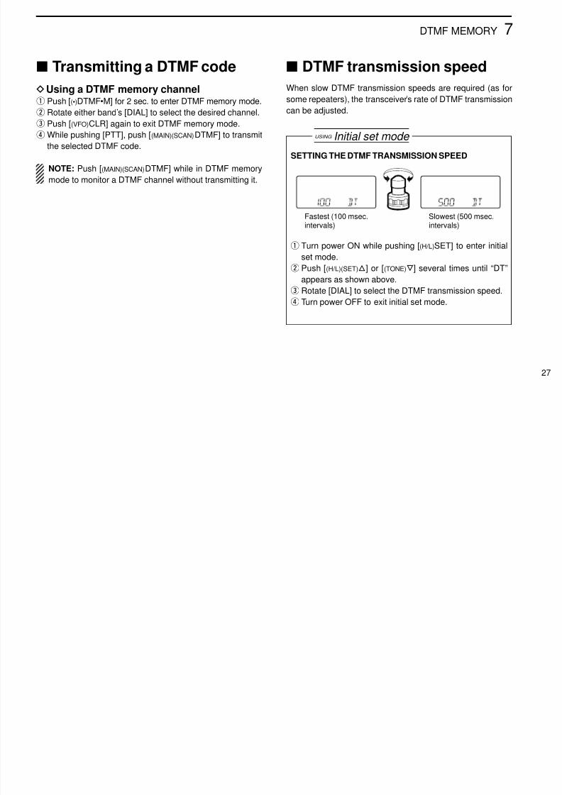
s DTMF transmission speedWhen slow DTMF transmission speeds are required (as forsome repeaters), the transceiver ’s rate of DTMF transmissioncan be adjusted.
s Transmitting a DTMF codeD Using a DTMF memory channelq
Push [ (•)DTMF•M] for 2 sec. to enter DTMF memory mode.w Rotate either band ’s [DIAL] to select the desired channel.e Push [ (VFO) CLR] again to exit DTMF memory mode.r While pushing [PTT], push [ (MAIN)(SCAN) DTMF] to transmit
the selected DTMF code.
NOTE: Push [ (MAIN)(SCAN) DTMF] while in DTMF memorymode to monitor a DTMF channel without transmitting it.
SETTING THE DTMF TRANSMISSION SPEED
q Turn power ON while pushing [ (H/L)SET] to enter initialset mode.
w Push [ (H/L)(SET) J ] or [ (TONE) K ] several times until “DT”appears as shown above.
e Rotate [DIAL] to select the DTMF transmission speed.
FULL SCAN (p. 29) Repeatedly scans all fre-quencies over the entireband.
PROGRAMMED SCAN(p. 29)
Repeatedly scans betweentwo user-programmed fre-quencies. Used for check-ing for frequencies within aspecified range such asrepeater output frequen-cies, etc.
SCAN RESUME CONDITION(p. 30) 4 resume conditions areavailable: pause scan and3 timer scans. Whenreceiving a signal, pausescan pauses until the sig-nal disappears; timer scanspause for 5, 10 or 15 sec.
Bandedge
Bandedge
Scan
Jump
Band edge orscan edge
Band edge orscan edge
FREQUENCY SKIP
FUNCTION (p. 31)
Skips unwanted frequen-
cies that inconvenientlystop scanning. This func-tion can be turned ON andOFF in scan set mode.
Each band has 3 scan types with skip functions and 4 resumeconditions providing scanning versatility. Scans on both bandscan be operated separately or simultaneously.
s Full/programmed scanq Assign the main band to the desired display with [MAIN].w Select VFO mode with [VFO].e Make sure the squelch is set to the threshold point.
• Select automatic squelch (AT) or a level (SQ1 – SQ8) where thenoise is muted. (p. 17)
r Push [ (MAIN)SCAN] for 2 sec. to start the programmedscan.• Decimal point ashes while scanning.• “P1 ” – “P5 ” ash to indicate which pair of scan edges is beingscanned.
• To change the scanning direction, rotate [DIAL].
• If the pocket beep function is activated, the transceiver automat-ically selects the tone squelch function when a scan starts.
t Push [1] – [5] to select the desired scan range or push [0]to select full scan.
y To stop the scan, push [ (VFO)CLR].
For programmed scan, scan edges must be programmedin advance. Program scan edges in the same manner asregular memory channels. (p. 22)
If the same frequencies are programmed into a pair ofscan edges, a programmed scan edge appears, such as“P1, ” but programmed scan does not proceed.
s Memory scanq Assign the main band to the desired display with [MAIN].w Select memory mode with [MR].e Make sure the squelch is set to the threshold point.
• Select automatic squelch (AT) or a level (SQ1 – SQ8) where thenoise is muted. (p. 17)
r Push [ (MAIN)SCAN] for 2 sec. to start the memory scan.• To change the scanning direction, rotate [DIAL].• If the pocket beep function is activated, the transceiver automat-ically selects the tone squelch function when a scan starts.
s Scan resume conditionThe resume condition can be selected as a pause or timerscan for each band (VHF VFO and memory channels, UHFVFO and memory channels, avionics* band).
s Skip channel settingMemory channels can be set to be skipped for memory skipscan. This is useful to speedup the memory skip scan inter-val.
q Select the memory channel to be programmed as a skipchannel: Push [MAIN] to select the desired band. Push [MR] to select memory mode. Rotate [DIAL] or push 2 digit keys to select the memory
channel.w Push [ (MR)SKIP] for 2 sec. to set the memory channel as a
skip channel.• “ ”appears.
e Repeat step w to cancel a skip channel.• “ ”disappears.S
S
8 SCAN OPERATION
30
Indicates the channel is setas a skip channel.
MAIN MAIN
SPush for2 sec.
MR
SKIP
q Turn power ON while pushing [ (MAIN)SCAN] to enterscan set mode.
w Push [ (H/L)J ] or [ (TONE) K ] several times to select the de-sired band to be set.• Avionics*/144/430(440) VFO, VHF/UHF memories are available.
e Rotate [DIAL] to select the desired resume condition.• “t-15 ”: scan pauses for 15 sec. on a received signal.• “t-10 ”: scan pauses for 10 sec. on a received signal.• “t-05 ”: scan pauses for 5 sec. on a received signal.• “P-02 ”: scan pauses on a received signal until it disappears.
r Turn power OFF to exit scan set mode.
USING Scan set mode
15 sec. timer for resumecondition
Pauses until the signaldisappears
*U.S.A. and Asia versions only.
SETTING THE SCAN RESUME CONDITION(Following displays show the 144 MHz band full/programmed scan)
s Frequency skip functionD Programming a skip frequencyUnwanted frequencies can be skipped and programmed asskip channels when full or programmed scan is pausing.
q Turn ON the frequency skip function as described at right.w Start full scan or programmed scan. (p. 29)e While receiving an unwanted signal and scan pauses,
push [ (S.MW) MW] for 2 sec. to program the received fre-quency as a skip frequency.• Do not release [ (S.MW) MW] before 2 sec., otherwise, scan stops
and select memory mode is selected.• The transceiver emits 3 beeps and the scan resumes.• Non-programmed memory channels are used for skip frequencyprogramming from channel 99 to 10 in reverse sequence.
• To scan the skip frequency after programming, cancel the skipinformation or clear the memory channel. (pgs. 25, 30)
NOTE: When the frequency skip function is turned OFF,the paused frequency is overwritten on the preselectedmemory channel.
D Frequency skip function ON/OFFThe frequency skip function can be turned OFF in set mode.In this case, the frequencies will not be skipped even if skipinformation is programmed and “ ” will not blink during fullscan or programmed scan.
S
SETTING THE FREQUENCY SKIP FUNCTION ON/OFF
q Turn power ON while pushing [ (MAIN)SCAN] to enterscan set mode.
w Push [ (H/L)J ] or [(TONE) K ] several times until “SKIP SC ”appears as shown above.
e Rotate [DIAL] to turn the frequency skip function ON orOFF.
s Tone squelch operationD OperationThe tone squelch opens only when receiving a signal con-taining a matching subaudible tone. You can silently wait forcalls from group members using the same tone.
q Assign the main band to the desired display with [MAIN].w Set the operating frequency.e Set the desired CTCSS tone in set mode.
• See right for programming.r Push [TONE] several times until “TSQL” appears.t When the received signal includes a matching tone,
squelch opens and the signal can be heard.• When the received signal ’s tone does not match, tone squelchdoes not open, however, the S-indicator shows signal strength.
• To open the squelch manually, push and hold [SQL].y Operate the transceiver in the normal way.u To cancel the tone squelch, push [TONE].
NOTE: The transceiver has 50 tone frequencies and con-sequently their spacing is narrow compared with units hav-ing 38 tones. Therefore, some tone frequencies mayreceive interference from adjacent tone frequencies.
CONVENIENT Store subaudible tone frequencies and tone squelch ON/OFFsettings in memories (call) for easy recall.
D Setting subaudible tones for [
tone squelch operation (CTCSS tones)Separate tone frequencies can be set for tone squelch oper-ation than for repeater operation (the same range of tones isavailable —see below). Like repeater tones, these are set inset mode.
q Select VFO or a memory channel.w Push [ (H/L)SET]for 2 sec. to enter
set mode.
e Push [ (H/L)(SET) J ] or [ (TONE) K ]several times until “CT ” appearsas shown at right.
r Rotate [DIAL] to select the de-sired subaudible tone.
s Tone scanThe transceiver can detect the subaudible tone frequency in areceived signal. By monitoring a signal that is being transmit-ted on a repeater input frequency, you can determine the tonefrequency required to access the repeater.
q Assign the main band to the desired display with [MAIN].w Set the desired frequency or memory channel to be
checked for a tone frequency.e Push [ (#)T SCAN] for 2 sec. to start the tone scan.
• To change the scanning direction, rotate [DIAL].r When the tone frequency is decoded, the set mode con-
tents are programmed with the tone frequency.• The tone scan pauses when a tone frequency is detected.• The decoded tone frequency is used for the tone encoder or toneencoder/decoder, depending on the the tone squelch ON/OFFsetting.
• “CT” or “RT” appears during tone scan when the tone squelch isin use or not.
t Push [VFO] to stop the scan.
s Pocket beep operationThis function uses subaudible tones for calling and can beused as a “common pager ” to inform you that someone hascalled while you were away from the transceiver.
D Waiting for a call from a speci c stationq Assign the main band to the desired display with [MAIN].w Set the operating frequency.e Set the desired CTCSS tone in set mode.
• See the opposite page for a list of available tone frequencies andprogramming information.
rPush [TONE] several times until “ TSQL
S” appears inthe function display.
t When a signal with the correct tone is received, the trans-ceiver emits beep tones for 30 sec. and flashes“ TSQL S .”
y Push [PTT] to answer or push [ (VFO)CLR] to stop the beepsand ashing.• Tone squelch is automatically selected.
D Calling a waiting station using pocket beepA subaudible tone matched with the station ’s tone frequencyis necessary. Use the tone squelch on the opposite page or asubaudible tone encoder.
MAIN
T
“RT ” or “CT” appearsduring tone scan
Subaudible tonefrequencies flash asthey are scanned.
s Guide functionThe transceiver has a guide function that enables quick de-scriptions of key functions without the need to search a menulist.
D Calling up a description Push the desired key while pushing the [L/G] key.
• “ ”and a quick description of the key ’s function appear.
[EXAMPLE]
While in set mode, memory name programming, etc., thequick description automatically appears 5 sec. after oper-ation. Push any key to clear the description.
GUIDE
MAIN GUIDEMAIN
L/G + MAIN
s Battery voltageindication
The transceiver has a battery voltage indicator to check drycell battery consumption in the BP-170 BATTERY CASE . Whenthe indication is set to ON, the battery voltage is indicated for2 sec. at power ON (LOW V, 4.5 – 16 V in 0.5 V steps).
If the battery voltage is lower than 4.5 V, “LOW V” appears.Place new dry cells in the battery case. If the voltage sur-passes 16 V, “OVER V ” appears and flashes regardless ofthis setting.
q Turn power ON while pushing[(H/L)SET] to enter initial set mode.
w Push [ (H/L)(SET) J ] or [ (TONE) K ]several times until “VO” appearsas shown at right.
e Rotate [DIAL] to turn the voltageindication ON or OFF.
r Turn power OFF to exit initial setmode.
After turning the voltage indica-tion ON, the battery voltage isdisplayed for 2 sec. at power ON.
The transceiver can be set to automatically turn OFF after aspeci ed period in which no switch is pushed.
60 min., 40 min., 20 min. and OFF can be specified. Thespecified period is retained even when the transceiver isturned OFF by the auto power-off function. To cancel thefunction, select “OFF ” in step e below.
q Turn power ON while pushing[(H/L)SET] to enter initial set mode.
w Push [ (H/L)(SET) J ] or [ (TONE) K ]several times until “AO” appearsas shown at right.
e Rotate [DIAL] to select the de-sired time or to turn the functionOFF.
r Turn power OFF to exit initial setmode.
After setting the auto power-offtime, the specified period is dis-played for 2 sec. at power ON.
USING Initial set mode s Function displaybacklighting
For easy operation at nighttime, the transceiver has an LCD(Liquid Crystal Display) and keypad lighting function.
5 sec. timer, manual and automatic can be speci ed. Whenset to 5 sec., display backlighting can be turned ON with 5sec. timer; when set to MANU (manual), the [L/G] key togglesdisplay backlighting ON and OFF; when set to AUTO, displaybacklighting automatically turns ON with 5 sec. timer whenany operation is performed except [PTT].
q Turn power ON while pushing[(H/L)SET] to enter initial set mode.
w Push [ (H/L)(SET) J ] or [ (TONE) K ]several times until “LI” appears asshown at right.
e Rotate [DIAL] to select the de-sired backlighting function.
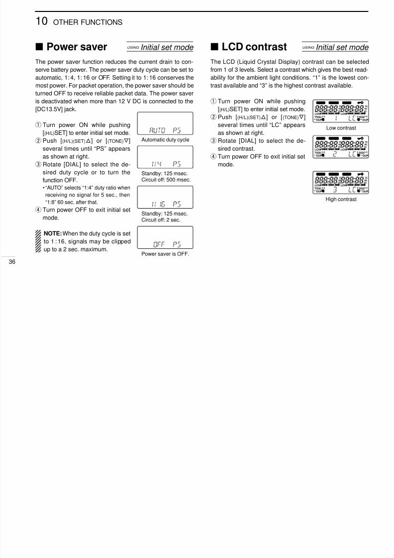
s LCD contrastThe LCD (Liquid Crystal Display) contrast can be selectedfrom 1 of 3 levels. Select a contrast which gives the best read-ability for the ambient light conditions. “1” is the lowest con-trast available and “3” is the highest contrast available.
q Turn power ON while pushing[(H/L)SET] to enter initial set mode.
w Push [ (H/L)(SET) J ] or [ (TONE) K ]several times until “LC” appearsas shown at right.
eRotate [DIAL] to select the de-sired contrast.
r Turn power OFF to exit initial setmode.
s Power saverThe power saver function reduces the current drain to con-serve battery power. The power saver duty cycle can be set toautomatic, 1: 4, 1: 16 or OFF. Setting it to 1: 16 conserves themost power. For packet operation, the power saver should beturned OFF to receive reliable packet data. The power saveris deactivated when more than 12 V DC is connected to the[DC13.5V] jack.
q Turn power ON while pushing[(H/L)SET] to enter initial set mode.
wPush [
(H/L)(SET) J] or [
(TONE) K]several times until “PS ” appears
as shown at right.e Rotate [DIAL] to select the de-
sired duty cycle or to turn thefunction OFF.• “AUTO” selects “1:4 ” duty ratio whenreceiving no signal for 5 sec., then“1:8 ” 60 sec. after that.
rTurn power OFF to exit initial setmode.
NOTE: When the duty cycle is setto 1 : 16, signals may be clippedup to a 2 sec. maximum.
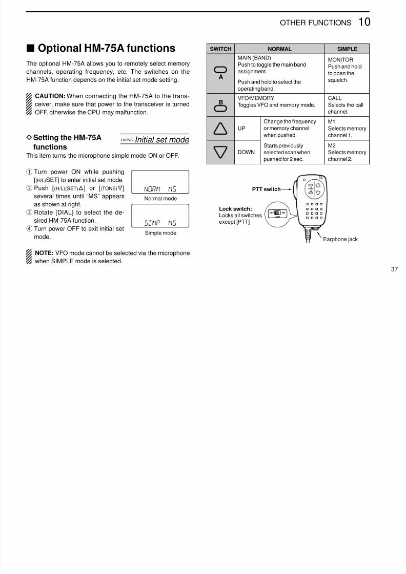
s Optional HM-75A functionsThe optional HM-75A allows you to remotely select memorychannels, operating frequency, etc. The switches on theHM-75A function depends on the initial set mode setting.
CAUTION: When connecting the HM-75A to the trans-ceiver, make sure that power to the transceiver is turnedOFF, otherwise the CPU may malfunction.
D Setting the HM-75A
functionsThis item turns the microphone simple mode ON or OFF.
q Turn power ON while pushing[(H/L)SET] to enter initial set mode.
w Push [ (H/L)(SET) J ] or [ (TONE) K ]several times until “MS ” appearsas shown at right.
e Rotate [DIAL] to select the de-sired HM-75A function.
r Turn power OFF to exit initial setmode.
NOTE: VFO mode cannot be selected via the microphonewhen SIMPLE mode is selected.
A
OFF ON
LOCK
B
Lock switch:Locks all switchesexcept [PTT]
Earphone jack
PTT switch
USING Initial set mode
Simple mode
Normal mode
SWITCH NORMAL SIMPLE
MAIN (BAND)Push to toggle the main bandassignment.
Push and hold to select theoperating band.
MONITORPush and holdto open thesquelch.
VFO/MEMORYToggles VFO and memory mode.
CALLSelects the callchannel.
UPM1Selects memorychannel 1.
DOWN M2Selects memorychannel 2.
Change the frequencyor memory channelwhen pushed.
Starts previouslyselected scan whenpushed for 2 sec.
s Partial resetIf you want to initialize the operating conditions (VFO fre-quency, VFO settings, set mode contents) without clearingthe memory contents, a partial resetting function is availablefor the transceiver.
While pushing [ (VFO)CLR], turn power ON to partially resetthe transceiver.
s All resetReset the CPU before operating the transceiver for the rsttime, or when the internal CPU malfunctions.
While pushing [SQL], [VFO] and [MR], turn power ON toreset the CPU.
CAUTION: Resetting the CPU returns all programmedcontents to their default settings.
AT POWER ON
AT POWER ON
s Handheld-to-handheldcloning
The information in the transceiver, such as memory channels,memory names, etc. can be transferred from one IC-W32A/Eto another. An optional OPC-474 CLONING CABLE is required.
In addition, optional CS-W32 CLONING SOFTWARE is availableto clone and edit contents using a PC.
q Connect the OPC-474 betweenboth transceiver ’s [SP] jacks.
w Turn the ‘slave ’ transceiver powerON.
e Turn the ‘master ’ transceiverpower ON while pushing [MR]and [M •N].• “PUSH PTT ” appears.
r Push [PTT] on the ‘master ’ trans-ceiver to transfer the data.• “CL OUT ” appears and digits (0 – 9,A – F) indicate the data ow.
If your transceiver seems to be malfunctioning, please checkthe following points before sending it to a service center.
PROBLEM POSSIBLE CAUSE SOLUTION REF.
• No power comes on. • The battery is exhausted.(A slight current ows in the circuits even whenthe power is OFF).
• Poor plug connection to the external DC powercable.
•Charge the battery pack or place new dry cellbatteries in the battery case.(Remove the battery pack if you will not be usingthe transceiver for a long time.)
•Check the connector or remove and replace thecable.
pgs.9, 10
—
• No sound comes fromthe speaker.
• Squelch level is too deep. (e.g. SQ8)• Volume level is too low.
•Set squelch to automatic (AT).•Set the desired band ’s [VOL] to a suitable level.
p. 17p. 17
• Transmitting is
impossible.
• The battery is exhausted.
• Avionics band frequency (U.S.A./Asia only) orweather channel (U.S.A. only) is selected.
•Charge the battery pack or place new dry cell
batteries in the battery case.• Set an amateur frequency.
pgs.
9, 10p. 13
• Frequency cannot be set. • Memory mode or call channel is selected.• Weather channel (U.S.A. only) is selected.
• Lock function is activated.
•Push [VFO] to select VFO mode.•Push [BAND] to select an amateur band oravionics band.
•Push [ (CALL)LOCK] for 2 sec. to cancel the
function.
p. 12p. 13
p. 15
• Scan does not start. • The squelch is open.
• Call or weather channel (U.S.A. only) isselected.
•Set squelch to automatic (AT) or the squelchclosed point (SQ1 or more).
•Push [BAND] to select an amateur band, memorychannel or avionics band.
p. 17
p. 13
• No contact possible withanother station.
• The transceiver is set to semi-duplex.• The output power is set to low.
Although the following chart refers mainly to the VHF (right) band, the samearrangement applies to the UHF (left) band (except commonly used mode, DTMFmemory, SCAN SET and INITIAL SET).
Bracketed values in the output power column refer to the UHF band. Operatingperiods are calibrated for the following conditions:
at 25 °C (77 °F), Tx (high power) : Rx : standby = 1 : 1 : 8
D Chargers and cablesBC-110A/D/V WALL CHARGERSRegularly charge battery packs.
BC-119 DESKTOP CHARGER + AD-51 DESKTOP CHARGER ADAPTERRapidly charge battery packs in 1 to 1.5 hrs. depending on the bat-tery pack. The AD-51 must be used with the BC-119 for charging abattery pack. Some BC-119 versions require the AD-75 additionally.The CP-17L or OPC-515L can be used instead of the supplied ACadapter.
CP-12/L CIGARETTE LIGHTER CABLE WITH NOISE FILTERFor operation and charging via a 12 V cigarette lighter socket.
OPC-254/L DC POWER CABLEFor operation and charging via an external power supply.
D Carrying caseLC-128 CARRYING CASE
D Speaker-microphones
D OthersMB-30 MOUNTING BRACKET
SP-13 EARPHONE
Provides clear receive audio in noisy environments.CS-W32 CLONING SOFTWARE + OPC-478 CLONING CABLEProvide quick and easy programming of memory channels, memorynames and set mode contents, etc.
OPC-474 CLONING CABLEUsed for handheld-to-handheld data cloning.
HM-46
HM-75A
HM-54
HS-85 HEADSET• PTT switch• VOX• One-touch PTT for
hands-free operation
When using the bracket hanger When using no bracket hanger
BATTERYPACK
HEIGHT(mm/in) VOLTAGE CAPACITY OUTPUT
POWEROPER.
PERIOD*
BP-17063.5/2.5
Battery case for
R6(AA) 4 alkaline cells 1.5 (1.3) W
Depends
on batteryBP-171 63.5/2.5 4.8 V 700 mAh 1.5 (1.3) W 5.5 (4.5) h
BP-172 63.5/2.5 4.8 V 950 mAh 1.5 (1.3) W 7.5 (6.0) h
BP-173 75.5/3.0 9.6 V 650 mAh 5.0 (4.5) W 3.5 (3.0) h
BP-180 75.5/3.0 7.2 V 600 mAh 3.5 (3.5) W 3.5 (3.0) h