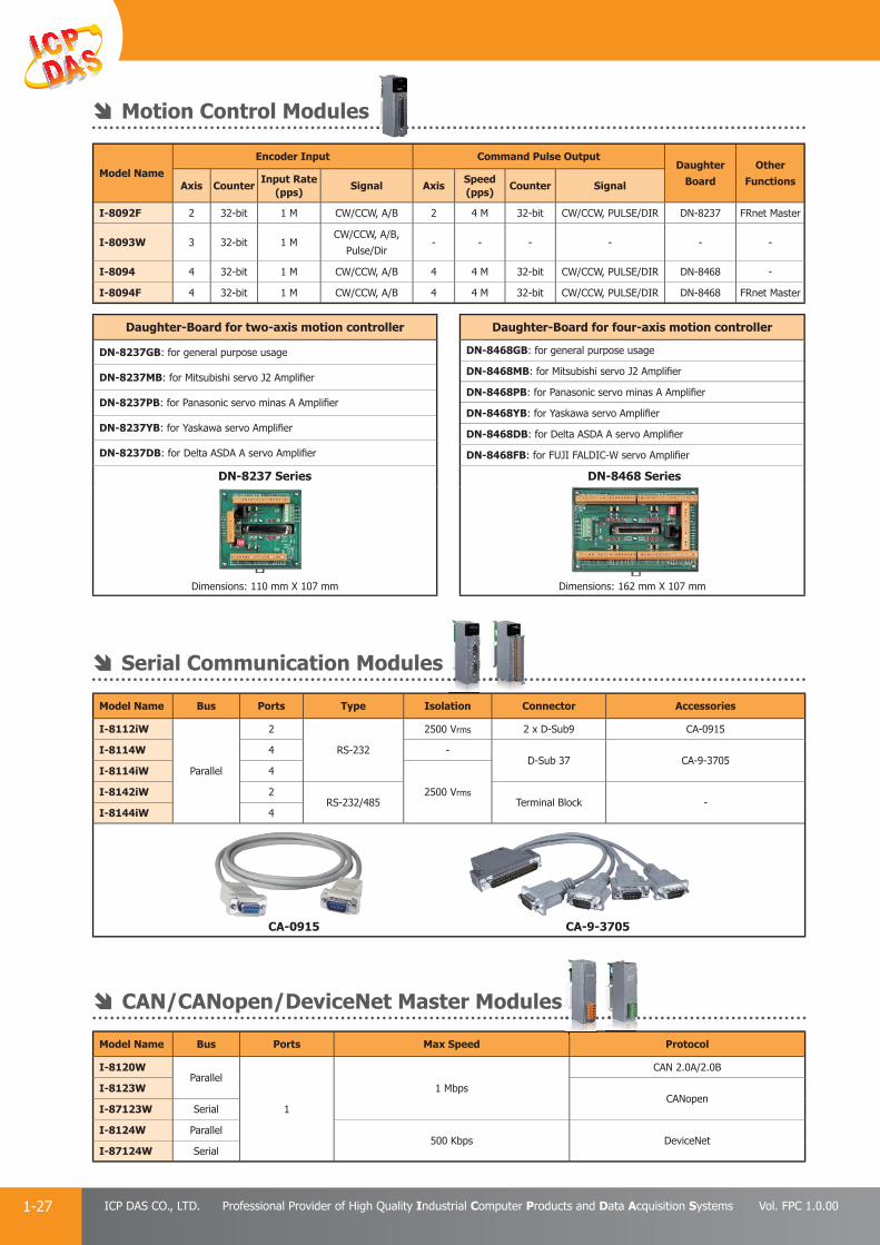
260
| Date post: | 22-Jan-2018 |
| Category: |
Engineering |
| Upload: | icp-das-usa-inc |
| View: | 97 times |
| Download: | 0 times |

EnergySolutions
Current SensorVoltage Attenuator
Communication Device(tGW/PDS I-7513/I-7514)
Remote I/O Modules(tM I/O M-7000 I/O ET-7000 I/O)
PM-3112/PM-3114
PM-3133/PM-3133-MTCPPMC-5151Motion Card MPAC + I-8092/I-8094
ET-M8194H
Motionnet Solutions
VPD seriesPower MeterPWM Modules(I-7088 + I-8088)
Awe
Switch HubMulti-Port Serial Card PDS/DS/tDS
RU-87Pn
ET-87Pn iDCS-8830
PROFIBUS
I-8K/I-87K X-board XW-boardXV-board
CAN RS-485/RS-422/RS-232
MiniOS7 FLASH ISaGRAF/Soft-GRAFMiniOS7 Studio NAPOPCLinux HMIWorks InduSoftRTU CenterQT
Softw
PAC
I/O
Automation To

BuildingAutomation
SMS series(GT-500 series)
RTU series(GT-540/G-4500)
RMV series(M2M-700 series)
GRP series(GRP-500 series)
GTM-201 seriesG-4500 series
Tiny I/O Series
TouchPAD
IR-310-RM
LC series
IR-210/IR-712A
HMI & ViewPAC(SV-2201-CE7/VP-25W1/VP-4131)
� �
��� � � � �
� � � �
0 1 2 3 4 5 6 7
0 1 2 3 4 5 6 7
� �
PFN-2019
Gateway Converter RF GSM/GPRS ZigBee Wi-Fi
Ethernet CAN PROFIBUSPROFINET
USB HART WISEFRnet BACnet EtherNet/IPGPRS/GSM ZigBee
(ZT Series)IR Wi-Fi
���� ��
������� � �� � �
�� �� � �
007
1 22 33 4 5 6 7
007
11 2 33 4 5 6 7
�� ��
PPPFFNN-2-2019F
eLoggerVxComm VCEPWISE EzDataLoggerUniDAQ SMS_DBVisual Studio.NET
ware
PCCard
Communication
otal Solutions

ICP DASICP DAS was established in 1993 and is strongly focused on innovation and the enhancement of industrial automation technology. ICP DAS continuously endeavors to develop a comprehensive selection of products ranging from remote I/O controllers, distributed I/O modules, I/O data acquisition boards, programmable automation controllers, industrial communication modules, web-related products, motion control systems, SCADA/HMI software to automation solutions for applications critical to energy management, motion automation, smart factories, intelligent buildings, and smart cities. Our ambition is to provide a wide range of high-quality products and versatile applications, together with prompt and effi cient service, that can be implemented to assist in the continued success of our clients worldwide.
Our Intelligent Solutions and Comprehensive Service, Your Key to Success.
Dear Customers,
Dear Business Partners,
The inevitable trend toward the implementation of the Internet of Things (IoT) and Industry 4.0 currently leads global cooperation and technology development, and the future demands and business opportunities in this area are potentially unlimited. We believe that one of the key success factors in the advancement of the automation industry is intelligence. Now, however, the evolution of the industry has entered into a phase of intelligent automation, ranging from a single domain with a limited scale to encompassing multiple domains on a signifi cantly expanded scale. Consequently, ICP DAS has transformed itself from simply a hardware provider to a provider of total automation solutions and service integration. As a result, our role in this industry has also been constantly evolving.
When looking back on our past development, we have come to realize that ICP DAS has already been intrinsically involved in the world of IoT and Industry 4.0.The integrated solutions provided by ICP DAS are a combination of both tangible products and intangible services which cover a variety of integrated application services and industry-oriented fi elds, including:
M2M Solutions
Energy Management
Motion Automation
Building Automation
Panel Solutions
SCADA, InduSoft Solutions
In addition to our close cooperation with worldwide distributors, ICP DAS has forged strong partnerships with those clients who have domain knowledge. We integrate the expertise of our clients with our ability for customization to offer products and services in line with needs. ICP DAS helps our customers to achieve success and that is both our goal and our passion.
At ICP DAS, we are committed to leveraging our considerable experience, our highly professional R&D capabilities, and our innovative products, as well as our dedication to service, in order to work together with you to seize the unquestionable future business opportunities that will arise from the increasing adoption of both IoT and Industry 4.0.
Yours faithfully,
Robert Chen
CEO, ICP DAS
Table of ContentsTable of ContentsP
anel
Pro
duct
sR
emot
e I/
O M
odu
le
and
Un
it
22
33
44
11
PA
C P
rodu
cts
Indu
stri
al
Com
mu
nic
atio
n
1. Compact PAC - - - - - - - - - - - - - - - - - - - - - P 1-1
2. 7188/7186 Series μPAC - - - - - - - - - - - - - - - P 1-31
3. 5000 Series μPAC - - - - - - - - - - - - - - - - - - - P 1-36
1. Multiport Serial Cards - - - - - - - - - - - - - - - - P 4-1
2. Serial Device Server - - - - - - - - - - - - - - - - - P 4-2
3. Converter/Repeater/Hub/Splitter - - - - - - - - - P 4-19
4. Ethernet Switch - - - - - - - - - - - - - - - - - - - - P 4-21
5. Fieldbus Solution - - - - - - - - - - - - - - - - - - - P 4-26
1. iPPC (Industrial Panel PC) - - - - - - - - - - - - - P 2-2
2. ViewPAC - - - - - - - - - - - - - - - - - - - - - - - - - P 2-4
3. IWS (InduSoft) - - - - - - - - - - - - - - - - - - - - P 2-8
4. SmartView - - - - - - - - - - - - - - - - - - - - - - - P 2-11
5. TouchPAD, ViewPAD - - - - - - - - - - - - - - - - - P 2-14
6. Touch Monitor - - - - - - - - - - - - - - - - - - - - - P 2-21
1. RS-485 I/O Products - - - - - - - - - - - - - - - - - P 3-2
2. Ethernet I/O Products - - - - - - - - - - - - - - - - P 3-24
3. CAN Bus I/O Products - - - - - - - - - - - - - - - - P 3-39
4. PROFIBUS I/O Products - - - - - - - - - - - - - - - P 3-41
5. FRnet Products - - - - - - - - - - - - - - - - - - - - P 3-44
6. WISE I/O Modules - - - - - - - - - - - - - - - - - - P 3-47

Mot
ion
Au
tom
atio
nEn
ergy
Man
agem
ent
Solu
tion
Acc
esso
ries
Wir
eles
s So
luti
on
77
88
99
66
55D
AQ
Car
d
1. Energy Management Solution - - - - - - - - - - - P 7-1
2. Back-End Management Software - - - - - - - - - P 7-2
3. Front-End Power Meter Concentrator - - - - - - P 7-5
4. Front-End Devices - - - - - - - - - - - - - - - - - - P 7-9
5. Applications - - - - - - - - - - - - - - - - - - - - - - P 7-18
1. Motionnet Solutions - - - - - - - - - - - - - - - - - P 6-1
2. Ethernet Motion Control Solutions - - - - - - - - P 6-9
3. PC-based Motion Control Cards - - - - - - - - - - P 6-13
4. PAC Solutions - Motion Modules - - - - - - - - - - P 6-20
5. Features of Motion Function - - - - - - - - - - - - P 6-23
1. Industrial Wireless Communication Products - - P 5-1
2. Radio Modems - - - - - - - - - - - - - - - - - - - - - P 5-2
3. 2G/3G Products - - - - - - - - - - - - - - - - - - - - P 5-3
4. WLAN Wireless Products - - - - - - - - - - - - - - P 5-5
5. ZigBee Products - - - - - - - - - - - - - - - - - - - - P 5-8
6. GPS Products - - - - - - - - - - - - - - - - - - - - - P 5-12
7. Infrared Products - - - - - - - - - - - - - - - - - - - P 5-13
1. Signal Conditioning Modules (SG-3000 Series) P 9-1
2. Surge Protection Module (SG-770) - - - - - - - - P 9-2
3. EMI Ferrite Split/Snap-On Core - - - - - - - - - - P 9-3
4. Relay Modules - - - - - - - - - - - - - - - - - - - - P 9-4
5. Enclosures and Mounting Kit - - - - - - - - - - - - P 9-5
6. MISC - - - - - - - - - - - - - - - - - - - - - - - - - - - P 9-6
1. PCI Express Data Acquisition Boards - - - - - - - P 8-3
2. PCI Bus Data Acquisition Boards - - - - - - - - - P 8-6
3. ISA Bus Data Acquisition Boards - - - - - - - - - P 8-13

Compact PAC P 1-11
● 1.1 XP-8000 and XP-8000-Atom Series - - - - - - - - - - - - - - - - - - - - - - - - P 1-12
● 1.2 WinPAC-8000 Series - - - - - - - - - - - - - - - - - - - - - - - - - - - - - - - - - P 1-15
● 1.3 LinPAC-8000 Series - - - - - - - - - - - - - - - - - - - - - - - - - - - - - - - - - - P 1-17
● 1.4 iPAC-8000 Series - - - - - - - - - - - - - - - - - - - - - - - - - - - - - - - - - - - - P 1-19
● 1.5 Industrial I/O Modules - - - - - - - - - - - - - - - - - - - - - - - - - - - - - - - - P 1-21
● 1.6 XP-9000 and WP-9000 Series - - - - - - - - - - - - - - - - - - - - - - - - - - - - P 1-29
5000 Series μPAC P 1-363
● 3.1 μPAC-5000 Series - - - - - - - - - - - - - - - - - - - - - - - - - - - - - - - - - - - P 1-36
● 3.2 WinPAC-5000 Series - - - - - - - - - - - - - - - - - - - - - - - - - - - - - - - - - P 1-40
● 3.3 LinPAC-5000 Series - - - - - - - - - - - - - - - - - - - - - - - - - - - - - - - - - - P 1-42
● 3.4 I/O Expansion Boards - - - - - - - - - - - - - - - - - - - - - - - - - - - - - - - - P 1-43
7188/7186 Series μPAC P 1-312
● 2.1 I/O Expansion Boards for 7188/7186 Series - - - - - - - - - - - - - - - - - - P 1-34
● 3.4 I/O Expansion Boards - - - - - - - - - - - - - - - - - - - - - - - - - - - - - - - - P 1-43
PAC ProductsPAC ProductsPAC Products 1
PAC Products
1-1 ICP DAS CO., LTD. Professional Provider of High Quality Industrial Computer Products and Data Acquisition Systems Vol. FPC 1.0.00
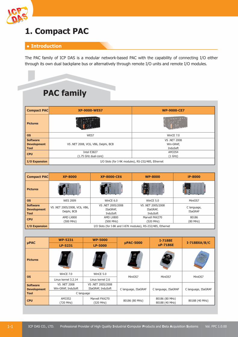
Compact PAC XP-9000-WES7 WP-9000-CE7
Pictures
OS WES7 WinCE 7.0
Software Development Tool
VS .NET 2008, VC6, VB6, Delphi, BCBVS .NET 2008
Win-GRAF, InduSoft
CPUIntel E3827
(1.75 GHz dual-core)AM3354(1 GHz)
I/O Expansion I/O Slots (for I-9K modules), RS-232/485, Ethernet
μPACWP-5231 WP-5000
μPAC-5000I-7188E
uP-7186EI-7188XA/B/C
LP-5231 LP-5000
Pictures
OSWinCE 7.0 WinCE 5.0
MiniOS7 MiniOS7 MiniOS7Linux kernel 3.2.14 Linux kernel 2.6
Software Development Tool
VS .NET 2008Win-GRAF, InduSoft
VS .NET 2005/2008ISaGRAF, InduSoft C language, ISaGRAF C language, ISaGRAF C language, ISaGRAF
C language
CPUAM3352
(720 MHz)Marvell PXA270
(520 MHz)80186 (80 MHz)
80186 (80 MHz)80188 (40 MHz)
80188 (40 MHz)
1. Compact PAC
PAC family
The PAC family of ICP DAS is a modular network-based PAC with the capability of connecting I/O either through its own dual backplane bus or alternatively through remote I/O units and remote I/O modules.
Compact PAC XP-8000 XP-8000-CE6 WP-8000 iP-8000
Pictures
OS WES 2009 WinCE 6.0 WinCE 5.0 MiniOS7
Software Development Tool
VS .NET 2005/2008, VC6, VB6, Delphi, BCB
VS .NET 2005/2008ISaGRAF, InduSoft
VS .NET 2005/2008ISaGRAF, InduSoft
C language, ISaGRAF
CPUAMD LX800 (500 MHz)
AMD LX800 (500 MHz)
Marvell PAX270 (520 MHz)
80186 (80 MHz)
I/O Expansion I/O Slots (for I-8K and I-87K modules), RS-232/485, Ethernet
● Introduction
PAC Products
1-2E-mail: [email protected] Vol. FPC 1.0.00
Website: http://www.icpdas.com
PA
C P
rodu
cts
Pan
el P
rodu
cts
Rem
ote
I/O
M
odul
e an
d U
nit
DA
Q C
ard
Indu
stri
al
Com
mun
icat
ion
Wir
eles
s So
luti
onM
otio
n
Au
tom
atio
nA
cces
sori
esEn
ergy
M
anag
emen
tSo
luti
on
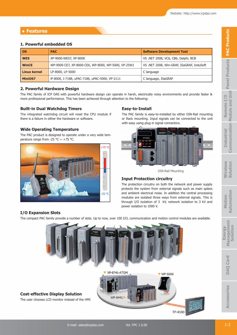
+75 °C
-25 °C
1. Powerful embedded OS
OS PAC Software Development Tool
WES XP-9000-WES7, XP-8000 VS .NET 2008, VC6, CB6, Delphi, BCB
WinCE WP-9000-CE7, XP-8000-CE6, WP-8000, WP-5000, VP-25W1 VS .NET 2008, Win-GRAF, ISaGRAF, InduSoft
Linux kernel LP-8000, LP-5000 C language
MiniOS7 iP-8000, I-7188, uPAC-7186, uPAC-5000, VP-2111 C language, ISaGRAF
● Features
Easy-to-InstallThe PAC family is easy-to-installed by either DIN-Rail mounting or Rack mounting. Input signals can be connected to the unit with easy using plug in signal connectors.
Input Protection circuitryThe protection circuitry on both the network and power supply protects the system from external signals such as main spikes and ambient electrical noise. In addition the central processing modules are isolated three ways from external signals. This is through I/O isolation of 3 kV, network isolation to 3 kV and power isolation to 1000 V.
Built-in Dual Watchdog TimersThe integrated watchdog circuit will reset the CPU module if there is a failure in either the hardware or software.
Wide Operating TemperatureThe PAC product is designed to operate under a very wide tem-perature range from -25 °C ~ +75 °C.
I/O Expansion SlotsThe compact PAC family provide a number of slots. Up to now, over 100 I/O, communication and motion control modules are available.
Cost-effective Display SolutionThe user chooses LCD monitor instead of the HMI
2. Powerful Hardware DesignThe PAC family of ICP DAS with powerful hardware design can operate in harsh, electrically noisy environments and provide faster & more professional performance. This has been achieved through attention to the following:
DIN-Rail Mounting
I
PAC Products
1-3 ICP DAS CO., LTD. Professional Provider of High Quality Industrial Computer Products and Data Acquisition Systems Vol. FPC 1.0.00
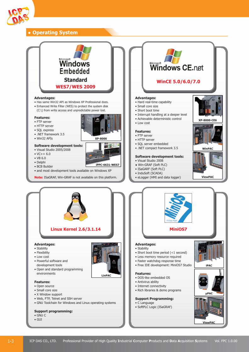
WinCE 5.0/6.0/7.0StandardWES7/WES 2009
XP-8000-CE6
ViewPAC
XP-8000
● Operating System
Advantages:• Hard real-time capability • Small core size• Short boot time• Interrupt handling at a deeper level • Achievable deterministic control• Low cost
Features:• FTP server• HTTP server• SQL server embedded• .NET compact framework 3.5
Software development tools:• Visual Studio 2008● Win-GRAF (Soft PLC)• ISaGARF (Soft PLC)• InduSoft (SCADA)• eLogger (HMI and data logger)
Advantages:• Has same Win32 API as Windows XP Professional does.• Enhanced Write Filter (WES) to protect the system disk
(C:\) from write access and unpredictable power lost.
Features:• FTP server• HTTP server• SQL express • .NET framework 3.5• Win32 APIs
Software development tools:• Visual Studio 2005/2008• VC++ 6.0• VB 6.0• Delphi• BCB Builder• and most development tools available on Windows XP
Note: ISaGRAF, Win-GRAF is not available on this platform.
Advantages:• Stability• Flexibility • Low cost• Powerful software and
development tools• Open and standard programming
environments
Features:• Open source • Small core size• X Window support• Web, FTP, Telnet and SSH server• GNU Toolchain for Windows and Linux operating systems
Support programming:• GNU C• GUI
MiniOS7Linux Kernel 2.6/3.1.14
WinPAC
iPAC
ViewPAC
μPACC
Advantages:• Stability• Short boot time period (<1 second)• Less memory resource required• Faster watchdog response time• Free IDE development: MiniOS7 Studio
Features:• DOS-like embedded OS• Antivirus ability• Internet connectivity• Rich libraries & demo programs
Support Programming:• C Language• SoftPLC Logic (ISaGRAF)
LinPAC
iPPC-6631-WES7

PAC Products
1-4E-mail: [email protected] Vol. FPC 1.0.00
Website: http://www.icpdas.com
PA
C P
rodu
cts
Pan
el P
rodu
cts
Rem
ote
I/O
M
odul
e an
d U
nit
DA
Q C
ard
Indu
stri
al
Com
mun
icat
ion
Wir
eles
s So
luti
onM
otio
n
Au
tom
atio
nA
cces
sori
esEn
ergy
M
anag
emen
tSo
luti
on
● Software
1. Win-GRAF (PAC / Soft PLC Development Kit)
Win-GRAF is a powerful SoftLogic development software and PLC-like SoftLogic package that supports IEC 61131-3 Standard Open PLC Languages running on Windows 7 and Windows 8. The Win-GRAF Runtime application can run on any ICP DAS PAC (Programmable Automation Controller) that supports the Win-GRAF, such as the WinPAC series WP-8xx8, WP-5xx8 and WP-9xx8-CE7, or the touch panel ViewPAC series VP-1238-CE7, VP-2208-CE7 and VP-4208-CE7, or the advanced CPU XPAC-CE6 series XP-8xx8-CE6. Using the Win-GRAF software with ICP DAS Win-GRAF PACs, the control/monitor systems can easily implement industrial level of data acquisition and logic control in various industry fi elds.
ment Kit)
• Win-GRAF Workbench Features:
Support IEC 61131-3 Standard Open PLC Languages: 1. Ladder Diagram (LD) 2. Function Block Diagram (FBD) 3. Sequential Function Chart (SFC) 4. Structured Text (ST) 5. Instruction List (IL)
Using ST Syntax in the FBD or LD Program
On Line Debug/Control/Monitor
Off Line Simulation on PC
On-Line Change: Replace the current running project to a new modified one without stopping the project
Event Triggered Data Binding: Exchange data between PACs.
Upload Source Code From PAC to PC
Recipe: Apply multi-recipes pre-defined in PC/ Win-GRAF to PAC.
Spy List: Show several selected variables in one Spy List window.
On-Line Change
Using ST in the LD or FBD
LD
• Win-GRAF PAC Features:
Support Soft-GRAF HMI
Soft-GRAF is a free HMI software by ICP DAS.
All WinCE Win-GRAF PACs support Soft-GRAF HMI, including: WP-8xx8, WP-5xx8, WP-9xx8-CE7, VP-1238-CE7, VP-2208-CE7, VP-4208-CE and XP-8xx8-CE6.
Provides various HMI Objects, such as: Button, Numeric Display, Trends, Angular Gauge, Alarm List, Logger, etc.
Applications: • Data Acquisition System • Factory Automation
• Building Automation• Remote I/O system
• Wireless Monitor/Control System• Motion Control System ...

PAC Products
1-5 ICP DAS CO., LTD. Professional Provider of High Quality Industrial Computer Products and Data Acquisition Systems Vol. FPC 1.0.00
Win-GRAF PAC Series Win-GRAF PAC Models
ViewPAC Series VP-1238-CE7, VP-2208-CE7, VP-4208-CE7
WinPAC Series WP-8148, WP-8448, WP-8848, WP-5238, WP-9xx8-CE7
XPAC-CE6 Series XP-8x48-CE6
Win-GRAF Development Software
Win-GRAF Workbench Win-GRAF Workbench Software (Large I/O Tags) with one USB Dongle
• Ordering Information:
Modbus Master Protocol Multi-port Modbus RTU, ASCII Master, RS-232/485/422 Modbus TCP Master (Multiple connections) Connect other Modbus PLC, Modbus Master, Modbus I/O and Modbus devices
Modbus Slave Protocol Multi-port Modbus RTU Slave, RS-232/485/422 Modbus TCP Slave (Multiple connections) Connect PC/SCADA/HMI
Support File Access & Data Log
Exchange Data Between PACsUp to 32 Win-GRAF PACs can use Data Binding to exchange application data andcontrol data to each other.
Support DCON I/OSupport RS-485 Port to connect the ICP DAS I-7000 I/O modules, and I-87K4/5/8/9 Expansion Unit plus I-87xxxW I/O boards, and RU-87P4/8 Expansion Unit plusI-87xxxW I/O boards.
Support a Variety of I/O BoardsSupport I-8xxxW and I-87xxxW I/O boards, such as: DI, DO, AI, AO, Relay, AC-IN, Thermistor, Thermocouple, RTD, Strain Gauge, Encoder, PWM output, Counter, Frequency, etc.
Support Temperature/Humidity Modules DL-100T485 and DL-100TM485.
Support Retain Variables WP-8xx8, WP-5xx8, WP-9xx8-CE7, VP-1238-CE7, VP-2208-CE7, VP-4208-CE7 and XP-8xx8-CE6. support retain variables. Suitable to retain the data changed quickly and frequently.
Protect Application by Own Algorithm Protect the Win-GRAF application by user-defined algorithm. Even others copy the application to the same model PAC, as long as he cannot get the source code, can not run the application correctly.
Redundant Solution XP-8xx8-CE6 support the Win-GRAF redundant system to achieve the more secure engineering applications.
Schedule-Control
Support VS 2008/VS 2010 Development:The Win-GRAF PACs support to use VS 2008 or VS 2010 (VB.net, C#) to develop user own HMI and data management programs, and can exchange variables with the Win-GRAF control programs.

PAC Products
1-6E-mail: [email protected] Vol. FPC 1.0.00
Website: http://www.icpdas.com
PA
C P
rodu
cts
Pan
el P
rodu
cts
Rem
ote
I/O
M
odul
e an
d U
nit
DA
Q C
ard
Indu
stri
al
Com
mun
icat
ion
Wir
eles
s So
luti
onM
otio
n
Au
tom
atio
nA
cces
sori
esEn
ergy
M
anag
emen
tSo
luti
on
Item ISaGRAF Ver. 3.xx C++ VS.net 2008
Programming Easy Hard Middle hard
Debug Easy Hard Middle hard
SoftLogic Yes No No
Program I/O Just connect and play Hard coding Hard coding
Communication
Already built-inModbus TCP,Modbus RTU,
Modbus ASCII,DCON, SMS,e-mail, TCP,
UDP, …
Hard coding Hard coding
2. ISaGRAF (SoftPLC Solution)
ISaGRAF is a powerful SoftLogic package on the industrial market. ISaGRAF Workbench is a PLC-like development software running on Windows 95/98/NT/2000/XP/Vista/7 and its ISaGRAF Runtime application programs can run on any ISaGRAF PACs such as WP-8xx7, VP-2xx7, XP-8xx7-CE6, iP-8xx7, μPAC-7186(P)EG etc. Using ISaGRAF PACs, the control/monitor systems can easily implement industrial level of real-time data acquisition and data/devices control via wiring or wireless network in various industries.
Application area: data acquisition system, distributed control system, factory and building automation, motor control, remote I/O system, wireless control system...
• ISaGRAF Workbench Features: Support IEC 61131-3 Standard Open PLC Languages
+ Flow Chart (FC) :1. Quick Ladder (LD)2. Function Block Diagram (FBD)3. Sequential Function Chart (SFC)4. Structured Text (ST)5. Instruction List (IL)6. Flow Chart (FC)
On-line debugging/control/monitor Off-line simulation On-line change (For WP-8xx7, VP-2xW7, XP-8xx7-CE6 only) Spotlight: Simple graphic HMI Auto-Scan I/O Uploading the program in the PAC
• ISaGRAF Solution Features: Support Soft-GRAF HMI
A free HMI software on the WinPAC, XPAC and ViewPAC Soft-GRAF Studio: simplify HMI screen editing (Mouse drag & drop)
Modbus Master Protocol Modbus RTU, ASCII, RS-232/485/422 Master Modbus TCP Master For connecting other Modbus PLCs, meters, I/Os and devices
Modbus Slave Protocol Modbus RTU (RS-232/485/422) Slave Modbus TCP/IP Slave For connecting other PC/HMI/SCADA (Ex. InduSoft)
and touch HMI (Ex. Touch-506T)
Data-Recorder & Data-Logger
Data Exchange Ebus: Through Ethernet Fbus: Through RS-485 PAC to PAC
CAN/CANopen
Via I-7530 to connect CAN/CANopen devices For connecting other CAN/CANopen meters, I/Os, devices
FRnet I/O Motion Control
For controlling server motors (P-command)
PAC can send e-mail to the internet
SMS: Short Message Service: GSM modem For reporting data and alarms to the operators
Wireless Communication: GPS, ZigBee & Radio
Auto-report Acquisition/Control Data
Redundant Solution : Hot-swap/Ethernet
Construction Stress Monitoring: VW sensor and Carlson strain gauge inputs solutions (Bridge/dam/building…)
Software Development: ISaGRAF V.S. C++ and VS.net 2008

PAC Products
1-7 ICP DAS CO., LTD. Professional Provider of High Quality Industrial Computer Products and Data Acquisition Systems Vol. FPC 1.0.00
3. Soft-GRAF HMI
• Soft-GRAF Studio: Create a Colorful HMI by Graphical Drag-and-Drop OperationSoft-GRAF Studio is an HMI (Human Machine Interface) software developed by ICP DAS which allows user to create his colorful HMI application running with the control logic in the same ISaGRAF WinCE series PAC: XP-8047-CE6/8347-CE6/8747-CE6, WP-8137/8437/8837, WP-8147/8447/8847 and VP-25W7/23W7 ISaGRAF PAC. User can edit the HMI screen by Soft-GRAF Studio using the graphical drag and drop operation. And use ISaGRAF to design the control logic by PLC Languages (Ladder, ST, FBD......).
• Soft-GRAF Studio Online Tutorial:The Soft-GRAF Studio website provides a tutorial video for online or downloaded learning. Through the seven and a half minutes, you will learn the software download, installation, HMI pages design and program downloading to the controller. Such a total tutoring will let you know that using the Soft-GRAF Studio is so easy!!
• My Sweet Home Demo Video:“My Sweet Home” is a simple demo of an interesting animated application. The intuitive operating HMI looked like the screen of mobile phones or tablet PC and you can test it intuitively even without connecting to the I/O modules. The “My Sweet Home” video is this demo operation video. By watching this video, customers can feel how powerful and how colorful of the Soft-GRAF Studio will be even it is a free software.
• Soft-GRAF Studio Features:
Soft-GRAF Studio:Easy HMI screen edit ing (Mouse drag and drop) No programming is required to implement HMI editing.
Support various and colorful HMI objects:Page (Max. 200, support password security)Numeric (Input, input security, display)Text (Dynamic/static text display)Picture (Animated/static picture display)Moving Trace (1-axis or 2-axis)Bar-meter (Vertical/horizontal dynamic display)Buttons displayed as textButtons displayed as PictureBuilt-in various objects (Will be more)
Multi-language:English, Traditional Chinese, Simplified Chinese, Russian, etc.
HMI behaves smoothly
op operation. And use ISaGRAF to design the control logic by PLC Languages (Ladder, ST, FBD
http://www.icpdas.com/products/Software/Soft-GRAF/soft-graf.htm

PAC Products
1-8E-mail: [email protected] Vol. FPC 1.0.00
Website: http://www.icpdas.com
PA
C P
rodu
cts
Pan
el P
rodu
cts
Rem
ote
I/O
M
odul
e an
d U
nit
DA
Q C
ard
Indu
stri
al
Com
mun
icat
ion
Wir
eles
s So
luti
onM
otio
n
Au
tom
atio
nA
cces
sori
esEn
ergy
M
anag
emen
tSo
luti
on
Features
WinPAC● Stable and high performance-to-price ratio small SCADA system● Rapidly and easily develop I/O integrated graphic supervisory control system
ViewPAC● Provide integrated touch HMI/SCADA system solution● Suitable for spatial narrow and small machine control system
XPAC● High performance and various Win32 API and Tool integrated SCADA system● Easily integrate third party software for multi-purpose application
XPAC-CE6● Provide the best choice for high effi ciency real time embedded system● Suitable for massive data acquisition and processing centralized system
4. InduSoft (SCADA Solution)
Introduction :InduSoft Web Studio is a powerful, integrated collection of automation tools that includes all the building blocks needed to develop modern Human Machine Interfaces (HMI), Supervisory Control and Data Acquisition (SCADA) systems, and embedded instrumentation and control applications. InduSoft Web Studio’s application runs in native Windows NT, 2000, XP, CE and CE .NET environments and conforms to industry standards such as Microsoft .NET, OPC, DDE, ODBC, XML, and ActiveX. We provide the InduSoft bundled driver to integrate InduSoft software into ICP DAS products (IO Modules: I-7000, I-8000, I-87K ; PACs: WinPAC, WinPAC, XPAC) for SCADA system.
Integrated with ICP DAS PACs :InduSoft has been integrated into ICP DAS various PACs including WinPAC, ViewPAC, XPAC and XPAC-CE6. The following is the advantages when using InduSoft with ICP DAS PACs.
Features:
• Elegant Graphics
• Multi-Language
• Database (Access, Excel, SQL, Oracle…)
• Recipes and Reports
• Online and History Alarm / Trend
• Various Communication Driver
(DCON, Modbus, OPC, DDE, TCP/IP…)
• Remote Web Client Control & Security
• ActiveX (GSM / SHM / COM /WEB provided by ICP DAS)
• System Redundancy
• Others (VBScript, E-mail, FTP, SNMP…)

PAC Products
1-9 ICP DAS CO., LTD. Professional Provider of High Quality Industrial Computer Products and Data Acquisition Systems Vol. FPC 1.0.00
5. EZ Data Logger
EZ Data Logger is the software that ICP DAS provides for users to easily build a SCADA system on Windows 2000/XP/Vista. It comes with two versions, "Lite" & "Professional". The Lite version is not only full-functioned but free to all ICP DAS users! EZ Data Logger is a small data logger software. It can be applied to small remote I/O system. With its user-friendly interface, users can quickly and easily build a data logger software without any programming skill.
Features:
• Support DCON, Modbus RTU, Modbus ASCII, Modbus TCP protocols
• Support multiple COM Ports and TCP/IP connections
• Support Virtual Channel defi nition
• Support Control Logic (VB Script)
• Support Alarm Notifi er (by sending SMS to cell phone or E-Mail)
• Flexible module confi guration (different description and color)
• Flexible workgroup confi guration
• Real time data trend (with zoom in and zoom out)
• Each trend line can store more than 86400 records.
• Provide Layout view
• Provide IP Camera Viewer
• Access database supported (can be exported to Excel fi le or CVS fi le)
• Provide Reporter to print trend line or data
• Provide High/Low alarm with audio warning
• Can search for DCON (I-7000/8000/87K) modules and Modbus(M-7000) serial modules
• Provide Value scaling
• All operations are done by click mouse and enter value.
PAC Products
1-10E-mail: [email protected] Vol. FPC 1.0.00
Website: http://www.icpdas.com
PA
C P
rodu
cts
Pan
el P
rodu
cts
Rem
ote
I/O
M
odul
e an
d U
nit
DA
Q C
ard
Indu
stri
al
Com
mun
icat
ion
Wir
eles
s So
luti
onM
otio
n
Au
tom
atio
nA
cces
sori
esEn
ergy
M
anag
emen
tSo
luti
on
3. HMI
• Elements: button, text box, linear gauge, angular gauge, LED numeral, LED indicator, tank, label, trend line.
4. Web Server
• Support elements: Text Box, Seven Segment, Label, Button, Picture Toggle.
• Support administrator login.
• Support browsers: Google Chrome, Internet Explorer, Firefox, Safari.
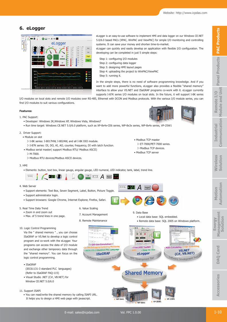
6. eLogger eLogger is an easy-to-use software to implement HMI and data logger on our Windows CE.NET
5.0/6.0 based PACs (XPAC, WinPAC and ViewPAC) for simple I/O monitoring and controlling
systems. It can save your money and shorten time-to-market.
eLogger can quickly and easily develop an application with fl exible I/O confi guration. The
developing can be completed in just 5 simple steps:
Step 1: confi guring I/O modules
Step 2: confi guring data logger
Step 3: designing HMI layout pages
Step 4: uploading the project to WinPAC/ViewPAC
Step 5: running it.
In the simple steps, there is no need of software programming knowledge. And if you
want to add more powerful functions, eLogger also provides a fl exible “shared memory”
interface to allow your VS.NET and ISaGRAF programs co-work with it. eLogger currently
supports I-87K series I/O modules on local slots. In the future, it will support I-8K series
I/O modules on local slots and remote I/O modules over RS-485, Ethernet with DCON and Modbus protocols. With the various I/O module series, you can
fi nd I/O modules to suit various confi gurations.
Features:
1. PAC Support:
• Developer: Windows 2K,Windows XP, Windows Vista, Windows7
• Run time target: Windows CE.NET 5.0/6.0 platform, such as XP-8x4x-CE6 series, WP-8x3x series, WP-8x4x series, VP-25W1
2. Driver Support:
• Module on slot
I-8K series: I-8017HW, I-8024W, and all I-8K DIO module.
I-87K series: DI, DO, AI, AO, counter, frequency, DI with latch function.
• Modbus serial master( support Modbus RTU/ Modbus ASCII)
M-7000.
Modbus RTU devices/Modbus ASCII devices.
6. Value Scaling
7. Account Management
8. Remote Maintenance
9. Data Base
• Local data base: SQL embedded.
• Remote data base: SQL 2005 on Windows platform.
10. Logic Control Programming
Via the " shared memory " , you can choose
ISaGRAF or VS.Net to develop a logic control
program and co-work with the eLogger. Your
programs can access the data of I/O module
and exchange other temporary data through
the "shared memory". You can focus on the
logic control programming.
• ISaGRAF
(IEC61131-3 standard PLC languages)
(Refer to ISaGRAF FAQ-115)
• Visual Studio .NET (C#, VB.NET) for
Window CE.NET 5.0/6.0
5. Real Time Data Trend • Zoom in and zoom out • Max. of 5 trend lines in one page.
11. Support ISAPI • You can read/write the shared memory by calling ISAPI URL. It helps you to design a HMI web page with javascript.
• Modbus TCP master
ET-7000/PET-7000 series.
Modbus TCP devices.
• Modbus TCP server
PAC Products
1-11 ICP DAS CO., LTD. Professional Provider of High Quality Industrial Computer Products and Data Acquisition Systems Vol. FPC 1.0.00
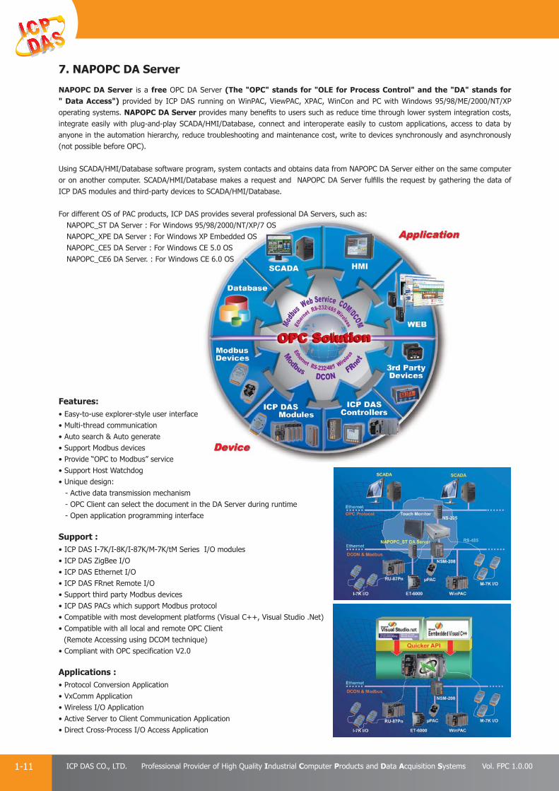
7. NAPOPC DA Server
NAPOPC DA Server is a free OPC DA Server (The "OPC" stands for "OLE for Process Control" and the "DA" stands for " Data Access") provided by ICP DAS running on WinPAC, ViewPAC, XPAC, WinCon and PC with Windows 95/98/ME/2000/NT/XP operating systems. NAPOPC DA Server provides many benefi ts to users such as reduce time through lower system integration costs, integrate easily with plug-and-play SCADA/HMI/Database, connect and interoperate easily to custom applications, access to data by anyone in the automation hierarchy, reduce troubleshooting and maintenance cost, write to devices synchronously and asynchronously (not possible before OPC). Using SCADA/HMI/Database software program, system contacts and obtains data from NAPOPC DA Server either on the same computer or on another computer. SCADA/HMI/Database makes a request and NAPOPC DA Server fulfi lls the request by gathering the data of ICP DAS modules and third-party devices to SCADA/HMI/Database.
For different OS of PAC products, ICP DAS provides several professional DA Servers, such as:NAPOPC_ST DA Server : For Windows 95/98/2000/NT/XP/7 OSNAPOPC_XPE DA Server : For Windows XP Embedded OSNAPOPC_CE5 DA Server : For Windows CE 5.0 OSNAPOPC_CE6 DA Server. : For Windows CE 6.0 OS
Features:• Easy-to-use explorer-style user interface• Multi-thread communication• Auto search & Auto generate• Support Modbus devices• Provide “OPC to Modbus” service• Support Host Watchdog• Unique design: - Active data transmission mechanism - OPC Client can select the document in the DA Server during runtime - Open application programming interface
Support :• ICP DAS I-7K/I-8K/I-87K/M-7K/tM Series I/O modules• ICP DAS ZigBee I/O• ICP DAS Ethernet I/O• ICP DAS FRnet Remote I/O• Support third party Modbus devices• ICP DAS PACs which support Modbus protocol• Compatible with most development platforms (Visual C++, Visual Studio .Net)• Compatible with all local and remote OPC Client
(Remote Accessing using DCOM technique)• Compliant with OPC specification V2.0
Applications :• Protocol Conversion Application• VxComm Application• Wireless I/O Application• Active Server to Client Communication Application• Direct Cross-Process I/O Access Application
PAC Products
1-12E-mail: [email protected] Vol. FPC 1.0.00
Website: http://www.icpdas.com
PA
C P
rodu
cts
Pan
el P
rodu
cts
Rem
ote
I/O
M
odul
e an
d U
nit
DA
Q C
ard
Indu
stri
al
Com
mun
icat
ion
Wir
eles
s So
luti
onM
otio
n
Au
tom
atio
nA
cces
sori
esEn
ergy
M
anag
emen
tSo
luti
on
Introduction
≒
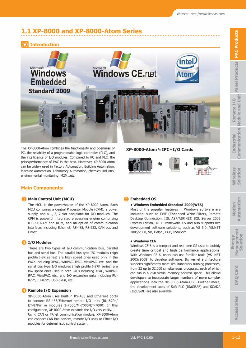
1.1 XP-8000 and XP-8000-Atom Series
+
XP-8000-Atom ≒ IPC+I/O CardsThe XP-8000-Atom combines the functionality and openness of PC, the reliability of a programmable logic controller (PLC), and the intelligence of I/O modules. Compared to PC and PLC, the price/performance of PAC is the best. Moreover, XP-8000-Atom can be widely used in Factory Automation, Building Automation, Machine Automation, Laboratory Automation, chemical industry, environmental monitoring, M2M…etc.
Standard 2009
Main Components:
Main Control Unit (MCU)The MCU is the powerhouse of the XP-8000-Atom. Each MCU comprises a Central Processor Module (CPM), a power supply, and a 1, 3, 7-slot backplane for I/O modules. The CPM is powerful integrated processing engine comprising a CPU, RAM and ROM, and an option of communication interfaces including Ethernet, RS-485, RS-232, CAN bus and FRnet.
I/O ModulesThere are two types of I/O communication bus, parallel bus and serial bus. The parallel bus type I/O modules (high profile I-8K series) are high speed ones used only in the PACs including XPAC, WinPAC, iPAC, ViewPAC, etc. And the serial bus type I/O modules (high profile I-87K series) are low speed ones used in both PACs including XPAC, WinPAC, iPAC, ViewPAC, etc., and I/O expansion units including RU-87Pn, ET-87Pn, USB-87Pn, etc.
Remote I/O ExpansionXP-8000-Atom uses built-in RS-485 and Ethernet ports to connect RS-485/Ethernet remote I/O units (RU-87Pn/ET-87Pn) or modules (I-7000/M-7000/ET-7000). In this confi guration, XP-8000-Atom expands the I/O very easily.Using CAN or FRnet communication module, XP-8000-Atom can connect CAN bus devices, remote I/O units or FRnet I/O modules for deterministic control system.
Embedded OS• Windows Embedded Standard 2009(WES)Most of the popular features in Windows software are included, such as EWF (Enhanced Write Filter), Remote Desktop Connection, IIS, ASP/ASP.NET, SQL Server 2005 Express Edition, .NET Framework 3.5 and also supports rich development software solutions, such as VS 6.0, VS.NET 2005/2008, VB, Delphi, BCB, InduSoft.
• Windows CE6Windows CE 6 is a compact and real-time OS used to quickly create time critical and high performance applications. With Windows CE 6, users can use familiar tools (VS .NET 2005/2008) to develop software. Its kernel architecture supports signifi cantly more simultaneously running processes, from 32 up to 32,000 simultaneous processes, each of which can run in a 2GB virtual memory address space. This allows developers to incorporate larger numbers of more complex applications into the XP-8000-Atom-CE6. Further more, the development tools of Soft PLC (ISaGRAF) and SCADA (InduSoft) are also available.

PAC Products
1-13 ICP DAS CO., LTD. Professional Provider of High Quality Industrial Computer Products and Data Acquisition Systems Vol. FPC 1.0.00
XP-8 xNO. of I/O Slot
xSoftware1: Standard
xHardware4: VGA 1600 x 1200
- Atom
● Appearance
GbE Ethernet Port 2CF Card Slot
XP-8041
XP-8741-Atom
XP-8341-Atom
COM4 (RS-232/RS-485)
COM5 (RS-232)
COM5(RS-232)
USB 2.0 Ports
USB 2.0 Ports
GbE Ethernet Port 1
MicrophoneAudio
GbE Ethernet Port 1
Power LED Indicator
Power LED IndicatorSystem LED Indicator
System LED Indicator
COM2 (RS-232)
GbE Ethernet Port 2CF Card Slot VGA Port
VGA Port
3 I/O Slots
7 I/O Slots
DIP switch
DIP switch
COM4 (RS-232/RS-485)
COM2 (RS-232)
MicrophoneAudio
Rotary Switch
Power Switch
Power and Ground
Frame Ground
Relay OutputR.COM and R.NO
Redundant Powerand Ground
COM1 (RS-232)
COM3 (RS-485)
XP-8 xNO. of I/O Slot
xSoftware1: Standard
xHardware4: VGA 1600 x 1200
Model Name OSPre-installed
SoftwareCPU Flash SDRAM
VGA Resolution
Ethernet Port
RS-232/RS-485
I/O Slot
XP-8141-Atom
WES 2009 None
Atom Z520, 1.33 GHz
16 GB DDR2 x 1 GB
1600 x 1200 2
4
1
XP-8341-Atom 3
XP-8741-Atom 7
XP-8041LX800,
500 MHz4 GB DDR x 1 GB
5 0
XP-83414
3
XP-8741 7
The controller supports following software development tools:1. DLLs of I/O modules for VS.NET 2005/2008 2. OPC server for SCADA software
Standard XPAC (Windows Embedded Standard 2009)
Hardware
Selection Guide
PAC Products
1-14E-mail: [email protected] Vol. FPC 1.0.00
Website: http://www.icpdas.com
PA
C P
rodu
cts
Pan
el P
rodu
cts
Rem
ote
I/O
M
odul
e an
d U
nit
DA
Q C
ard
Indu
stri
al
Com
mun
icat
ion
Wir
eles
s So
luti
onM
otio
n
Au
tom
atio
nA
cces
sori
esEn
ergy
M
anag
emen
tSo
luti
on
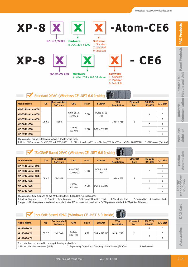
Model Name OSPre-installed
SoftwareCPU Flash SDRAM
VGA Resolution
Ethernet Port
RS-232/RS-485
I/O Slot
XP-8141-Atom-CE6
CE 6.0 None
Atom Z510,1.10 GHz
8 GBDDR2 x 512
MB
1024 x 768 2
4
1
XP-8341-Atom-CE6 3
XP-8741-Atom-CE6 7
XP-8041-CE6LX800,
500 MHz4 GB DDR x 512 MB
5 0
XP-8341-CE64
3
XP-8741-CE6 7
The controller supports following software development tools:1. DLLs of I/O modules for eVC, VS.Net 2005/2008 2. DLLs of Modbus/RTU and Modbus/TCP for eVC and VS.Net 2005/2008 3. OPC server (Quicker)
Model Name OSPre-installed
SoftwareCPU Flash SDRAM
VGA Resolution
Ethernet Port
RS-232/RS-485
I/O Slot
XP-8147-Atom-CE6
CE 6.0 ISaGRAF
Atom Z510 (1.10 GHz)
8 GBDDR2 x 512
MB
1024 x 768 2
4
1
XP-8347-Atom-CE6 3
XP-8747-Atom-CE6 7
XP-8047-CE6LX800,
500 MHz4 GB DDR x 512 MB
5 0
XP-8347-CE64
3
XP-8747-CE6 7
The controller fully supports all fi ve of the IEC61131-3 standard PLC languages:1. Ladder diagram, 2. Function block diagram, 3. Sequential function chart, 4. Structured text, 5. Instruction List plus fl ow chart. It supports Modbus protocol and can link to distributed I/O modules with Modbus or DCON protocol via the RS-232/485 or Ethernet.
Model Name OSPre-installed
SoftwareCPU Flash SDRAM
VGA Resolution
Ethernet Port
RS-232/RS-485
I/O Slot
XP-8049-CE6
CE 6.0 InduSoftLX800,
500 MHz4 GB DDR x 512 MB 1024 x 768 2
5 0
XP-8349-CE64
3
XP-8749-CE6 7
The controller can be used to develop following applications:1. Human Machine Interfaces (HMI) 2. Supervisory Control and Data Acquisition System (SCADA) 3. Web server
XP-8 xNO. of I/O Slot
xSoftware1: Standard7: ISaGRAF9: InduSoft
xHardware4: VGA 1600 x 1200
Standard XPAC (Windows CE .NET 6.0 Inside)
ISaGRAF Based XPAC (Windows CE .NET 6.0 Inside)
InduSoft Based XPAC (Windows CE .NET 6.0 Inside)
-Atom-CE6
XP-8 x x xNO. of I/O Slot Software
1: Standard7: ISaGRAF9: InduSoft
Hardware4: VGA 1024 x 768 OR above
- CE6

PAC Products
1-15 ICP DAS CO., LTD. Professional Provider of High Quality Industrial Computer Products and Data Acquisition Systems Vol. FPC 1.0.00
1.2 WinPAC-8000 Series
≒ +
WinPAC-8000 is the new generation PAC of ICP DAS. It is equipped a PXA270 CPU (520 MHz) running a Windows CE.NET 5.0 operating system, various connectivities (VGA, USB, Ethernet, RS-232/485) and 1/4/8 slots for high performance Parallel I/O modules (high profi le I-8K series) and serial I/O modules (high profi le I-87K I/O modules).
Compared with the fi rst generation WinCon-8000, WinPAC-8000 not only improves the CPU performance (from 206 MHz to 520 MHz) and upgrading OS (from CE 4.1 to CE 5.0), but also adds many reliability features, such as dual LAN, redundant power inputs, dual battery backup SRAM. It gives you all of the best features of both traditional PLCs and Windows capable PCs.
WinPAC operating system, Windows CE 5.0, has many advantages, including hard real-time capability, small core size, short boot time, interrupt handling at a deeper level, achievable deterministic control, and low cost. Using Windows CE.Net 5.0 in the WinPAC-8000 gives it the ability to run PC-based Control software such as Visual Basic.NET, Visual C#, Embedded Visual C++, SCADA software, SoftPLC.
WinPAC ≒ IPC+PLC
Main Components:
Main Control Unit (MCU)The MCU is the powerhouse of the WinPAC-8000. Each MCU comprises a Central Processor Module (CPM), a power supply, and a 1, 4, 8-slot backplane for 1, 4, 8 I/O modules. The CPM is powerful integrated processing engine comprising a CPU, RAM and ROM, and an option of communication interfaces including Ethernet, RS-485, CAN bus and FRnet.
I/O ModulesThere are two types of I/O communication bus, parallel bus and serial bus. The parallel bus type I/O modules (high profi le I-8K series) are high speed ones used only in the PACs including XPAC, WinPAC, iPAC, ViewPAC, etc. And the serial bus type I/O modules (high profi le I-87K series) are low speed ones used in both PACs including XPAC, WinPAC, iPAC, ViewPAC, etc., and I/O expansion units including RU-87Pn, ET-87Pn, USB-87Pn, etc.
Embedded OSAll WinPAC have Windows CE OS inside, and most of the popular features in MS software are included, such as FTP Server, HTTP Server, ASP (Java/VB script), SQL Server embedded 3.5 and compact .NET Framework 3.5. WinPAC supports rich software & development solutions: VB.Net 2005/2008, Visual C#.NET 2005/2008, eVC++ 4.0, ISaGRAF, InduSoft.
Remote I/O ExpansionWinPAC uses built-in RS-485 and Ethernet ports to connect RS-485/Ethernet remote I/O units (Ru-87Pn/ET-87Pn) or modules (I-7000/M-7000/ET-7000). In this confi guration, WinPAC expands the I/O very easily. Using CAN or FRnet communication module, WinPAC can connect CAN bus devices, remote I/O units or FRnet I/O modules for deterministic control system.
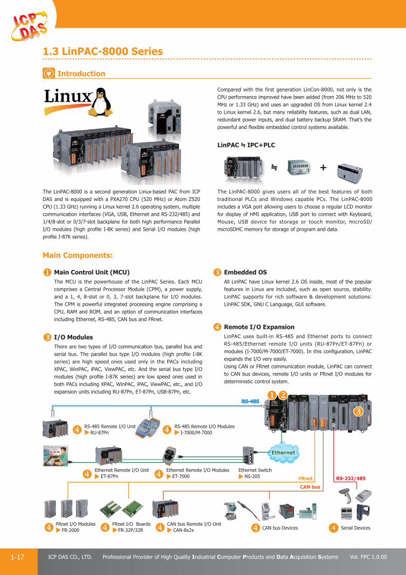
Ethernet Ethernet
RS-485RS-485
Ethernet Switch NS-205
Ethernet Remote I/O Unit ET-87Pn
FRnet I/O Modules FR-2000
FRnet I/O Boards FR-32P/32R
CAN bus Remote I/O Unit CAN-8x2x CAN bus Devices Serial Devices
Ethernet Remote I/O Modules ET-7000 RS-232/485
CAN bus
FRnet
RS-485 Remote I/O Modules I-7000/M-7000
RS-485 Remote I/O Unit RU-87Pn
Introduction

PAC Products
1-16E-mail: [email protected] Vol. FPC 1.0.00
Website: http://www.icpdas.com
PA
C P
rodu
cts
Pan
el P
rodu
cts
Rem
ote
I/O
M
odul
e an
d U
nit
DA
Q C
ard
Indu
stri
al
Com
mun
icat
ion
Wir
eles
s So
luti
onM
otio
n
Au
tom
atio
nA
cces
sori
esEn
ergy
M
anag
emen
tSo
luti
on
Model Name OSPre-installed
SoftwareCPU Flash SDRAM
VGA Resolution
USB RS-232/RS-485 I/O Slot Memory Expansion
WP-8137
CE 5.0 ISaGRAFPXA270,520 MHz
128 MB 128 MB 1024 x 768 2
2 1
microSDWP-84374
4
WP-8837 8
WP-8147
CE 5.0 ISaGRAFPXA270,520 MHz
96 MB 128 MB 800 x 600 1
2 1
microSDWP-84474
4
WP-8847 8
Model Name OSPre-installed
SoftwareCPU Flash SDRAM
VGA Resolution
USB RS-232/RS-485 I/O Slot Memory Expansion
WP-8148
CE 5.0 Win-GRAFPXA270,520 MHz
96 MB 128 MB 800 x 600 1
2 1
microSDWP-84484
4
WP-8848 8
WP-8 x x x xxNO. of I/O Slot Software
1: Standard7: ISaGRAF8: Win-GRAF9: InduSoft
Hardware3: PXA270 CPU & VGA 1024 x 7684: PXA270 CPU & VGA 800 x 600
LanguageEN: EnglishTC: Traditional ChineseSC: Simplifi ed Chinese
ISaGRAF Based WinPAC
Win-GRAF Based WinPAC
-
Model Name OSPre-installed
SoftwareCPU Flash SDRAM
VGA Resolution
USB RS-232/RS-485 I/O Slot Memory Expansion
WP-8139
CE 5.0 InduSoftPXA270,520 MHz
128 MB 128 MB 1024 x 768 2
2 1
microSDWP-84394
4
WP-8839 8
WP-8149
CE 5.0 InduSoftPXA270,520 MHz
96 MB 128 MB 800 x 600 1
2 1
microSDWP-84494
4
WP-8849 8
InduSoft Based WinPAC
Model Name OSPre-installed
SoftwareCPU Flash SDRAM
VGA Resolution
USB RS-232/RS-485 I/O Slot Memory Expansion
WP-8131
CE 5.0 NonePXA270,520 MHz
128 MB 128 MB 1024 x 768 2
2 1
microSDWP-84314
4
WP-8831 8
WP-8141
CE 5.0 NonePXA270,520 MHz
96 MB 128 MB 800 x 600 1
2 1
microSDWP-84414
4
WP-8841 8
The controller supports the following software development tools:
1. DLLs of I/O modules for eVC, VS.Net 2008/2010
2. DLLs of Modbus/RTU and Modbus/TCP for eVC and VS.Net 2008/2010
Standard WinPAC
Selection Guide
PAC Products
1-17 ICP DAS CO., LTD. Professional Provider of High Quality Industrial Computer Products and Data Acquisition Systems Vol. FPC 1.0.00
1.3 LinPAC-8000 Series
The LinPAC-8000 is a second generation Linux-based PAC from ICP DAS and is equipped with a PXA270 CPU (520 MHz) or Atom Z520 CPU (1.33 GHz) running a Linux kernel 2.6 operating system, multiple communication interfaces (VGA, USB, Ethernet and RS-232/485) and 1/4/8-slot or 0/3/7-slot backplane for both high performance Parallel I/O modules (high profi le I-8K series) and Serial I/O modules (high profi le I-87K series).
The LinPAC-8000 gives users all of the best features of both traditional PLCs and Windows capable PCs. The LinPAC-8000 includes a VGA port allowing users to choose a regular LCD monitor for display of HMI application, USB port to connect with Keyboard, Mouse, USB device for storage or touch monitor, microSD/microSDHC memory for storage of program and data.
Compared with the first generation LinCon-8000, not only is the CPU performance improved have been added (from 206 MHz to 520 MHz or 1.33 GHz) and uses an upgraded OS from Linux kernel 2.4 to Linux kernel 2.6, but many reliability features, such as dual LAN, redundant power inputs, and dual battery backup SRAM. That’s the powerful and fl exible embedded control systems available.
LinPAC ≒ IPC+PLC
4
Main Components:
Main Control Unit (MCU)The MCU is the powerhouse of the LinPAC Series. Each MCU comprises a Central Processor Module (CPM), a power supply, and a 1, 4, 8-slot or 0, 3, 7-slot backplane for I/O modules. The CPM is powerful integrated processing engine comprising a CPU, RAM and ROM, and an option of communication interfaces including Ethernet, RS-485, CAN bus and FRnet.
I/O ModulesThere are two types of I/O communication bus, parallel bus and serial bus. The parallel bus type I/O modules (high profi le I-8K series) are high speed ones used only in the PACs including XPAC, WinPAC, iPAC, ViewPAC, etc. And the serial bus type I/O modules (high profi le I-87K series) are low speed ones used in both PACs including XPAC, WinPAC, iPAC, ViewPAC, etc., and I/O expansion units including RU-87Pn, ET-87Pn, USB-87Pn, etc.
Embedded OSAll LinPAC have Linux kernel 2.6 OS inside, most of the popular features in Linux are included, such as open source, stability. LinPAC supports for rich software & development solutions: LinPAC SDK, GNU C Language, GUI software.
Remote I/O ExpansionLinPAC uses built-in RS-485 and Ethernet ports to connect RS-485/Ethernet remote I/O units (RU-87Pn/ET-87Pn) or modules (I-7000/M-7000/ET-7000). In this confi guration, LinPAC expands the I/O very easily.Using CAN or FRnet communication module, LinPAC can connect to CAN bus devices, remote I/O units or FRnet I/O modules for deterministic control system.
Ethernet Ethernet
RS-485RS-485
Ethernet Switch NS-205
Ethernet Remote I/O Unit ET-87Pn
FRnet I/O Modules FR-2000
FRnet I/O Boards FR-32P/32R
CAN bus Remote I/O Unit CAN-8x2x CAN bus Devices Serial Devices
Ethernet Remote I/O Modules ET-7000 RS-232/485
CAN bus
FRnet
RS-485 Remote I/O Modules I-7000/M-7000
RS-485 Remote I/O Unit RU-87Pn
≒ +
Introduction
PAC Products
1-18E-mail: [email protected] Vol. FPC 1.0.00
Website: http://www.icpdas.com
PA
C P
rodu
cts
Pan
el P
rodu
cts
Rem
ote
I/O
M
odul
e an
d U
nit
DA
Q C
ard
Indu
stri
al
Com
mun
icat
ion
Wir
eles
s So
luti
onM
otio
n
Au
tom
atio
nA
cces
sori
esEn
ergy
M
anag
emen
tSo
luti
on
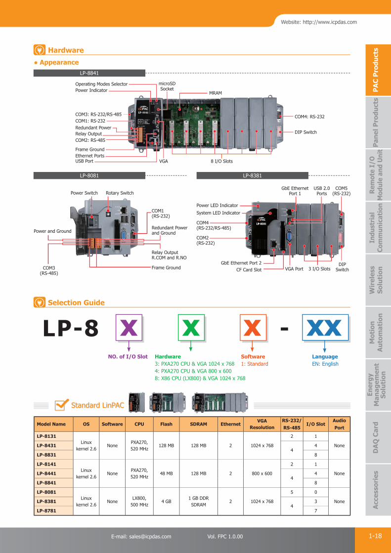
● Appearance
LP-8081
LP-8841
LP-8381
COM4(RS-232/RS-485)
COM5(RS-232)
USB 2.0Ports
GbE EthernetPort 1
Power LED Indicator
System LED Indicator
COM2(RS-232)
GbE Ethernet Port 2CF Card Slot VGA Port 3 I/O Slots
DIP Switch
Power IndicatorOperating Modes Selector microSD
SocketMRAM
COM4: RS-232
DIP Switch
COM3: RS-232/RS-485COM1: RS-232Redundant PowerRelay Output
Frame Ground
COM2: RS-485
USB Port VGA 8 I/O SlotsEthernet Ports
Model Name OS Software CPU Flash SDRAM EthernetVGA
ResolutionRS-232/RS-485
I/O SlotAudio Port
LP-8131Linux
kernel 2.6None
PXA270,520 MHz
128 MB 128 MB 2 1024 x 768
2 1
NoneLP-84314
4
LP-8831 8
LP-8141Linux
kernel 2.6None
PXA270,520 MHz
48 MB 128 MB 2 800 x 600
2 1
NoneLP-84414
4
LP-8841 8
LP-8081Linux
kernel 2.6None
LX800,500 MHz
4 GB1 GB DDRSDRAM
2 1024 x 768
5 0
NoneLP-83814
3
LP-8781 7
LP-8 x x x xxNO. of I/O Slot Software
1: StandardHardware3: PXA270 CPU & VGA 1024 x 7684: PXA270 CPU & VGA 800 x 6008: X86 CPU (LX800) & VGA 1024 x 768
LanguageEN: English
Standard LinPAC
-
Rotary SwitchPower Switch
Power and Ground
Frame Ground
Relay OutputR.COM and R.NO
Redundant Powerand Ground
COM1(RS-232)
COM3(RS-485)
Hardware
Selection Guide
PAC Products
1-19 ICP DAS CO., LTD. Professional Provider of High Quality Industrial Computer Products and Data Acquisition Systems Vol. FPC 1.0.00
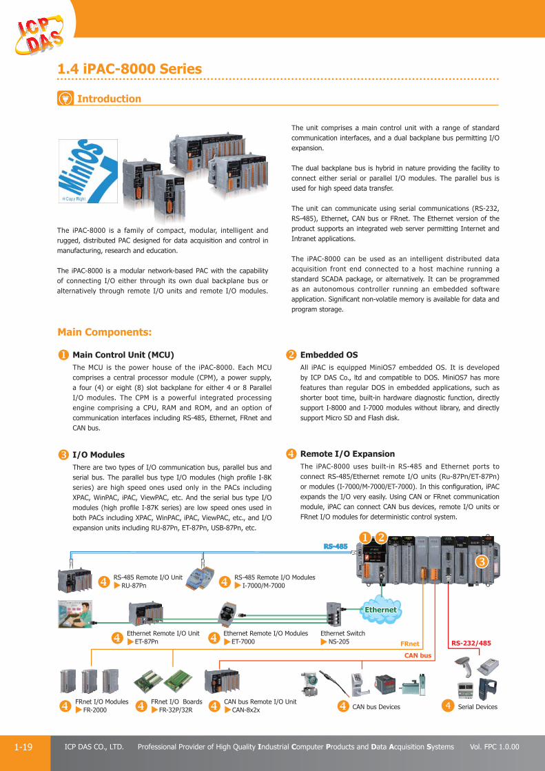
1.4 iPAC-8000 Series
Main Components:
Main Control Unit (MCU)The MCU is the power house of the iPAC-8000. Each MCU comprises a central processor module (CPM), a power supply, a four (4) or eight (8) slot backplane for either 4 or 8 Parallel I/O modules. The CPM is a powerful integrated processing engine comprising a CPU, RAM and ROM, and an option of communication interfaces including RS-485, Ethernet, FRnet and CAN bus.
I/O ModulesThere are two types of I/O communication bus, parallel bus and serial bus. The parallel bus type I/O modules (high profi le I-8K series) are high speed ones used only in the PACs including XPAC, WinPAC, iPAC, ViewPAC, etc. And the serial bus type I/O modules (high profi le I-87K series) are low speed ones used in both PACs including XPAC, WinPAC, iPAC, ViewPAC, etc., and I/O expansion units including RU-87Pn, ET-87Pn, USB-87Pn, etc.
Embedded OSAll iPAC is equipped MiniOS7 embedded OS. It is developed by ICP DAS Co., ltd and compatible to DOS. MiniOS7 has more features than regular DOS in embedded applications, such as shorter boot time, built-in hardware diagnostic function, directly support I-8000 and I-7000 modules without library, and directly support Micro SD and Flash disk.
Remote I/O ExpansionThe iPAC-8000 uses built-in RS-485 and Ethernet ports to connect RS-485/Ethernet remote I/O units (Ru-87Pn/ET-87Pn) or modules (I-7000/M-7000/ET-7000). In this confi guration, iPAC expands the I/O very easily. Using CAN or FRnet communication module, iPAC can connect CAN bus devices, remote I/O units or FRnet I/O modules for deterministic control system.
The iPAC-8000 is a family of compact, modular, intelligent and rugged, distributed PAC designed for data acquisition and control in manufacturing, research and education.
The iPAC-8000 is a modular network-based PAC with the capability of connecting I/O either through its own dual backplane bus or alternatively through remote I/O units and remote I/O modules.
The unit comprises a main control unit with a range of standard communication interfaces, and a dual backplane bus permitting I/O expansion.
The dual backplane bus is hybrid in nature providing the facility to connect either serial or parallel I/O modules. The parallel bus is used for high speed data transfer.
The unit can communicate using serial communications (RS-232, RS-485), Ethernet, CAN bus or FRnet. The Ethernet version of the product supports an integrated web server permitting Internet and Intranet applications.
The iPAC-8000 can be used as an intelligent distributed data acquisition front end connected to a host machine running a standard SCADA package, or alternatively. It can be programmed as an autonomous controller running an embedded software application. Signifi cant non-volatile memory is available for data and program storage.
4
Ethernet Ethernet
RS-485RS-485
Ethernet Switch NS-205
Ethernet Remote I/O Unit ET-87Pn
FRnet I/O Modules FR-2000
FRnet I/O Boards FR-32P/32R
CAN bus Remote I/O Unit CAN-8x2x CAN bus Devices Serial Devices
Ethernet Remote I/O Modules ET-7000 RS-232/485
CAN bus
FRnet
RS-485 Remote I/O Modules I-7000/M-7000
RS-485 Remote I/O Unit RU-87Pn
Introduction

PAC Products
1-20E-mail: [email protected] Vol. FPC 1.0.00
Website: http://www.icpdas.com
PA
C P
rodu
cts
Pan
el P
rodu
cts
Rem
ote
I/O
M
odul
e an
d U
nit
DA
Q C
ard
Indu
stri
al
Com
mun
icat
ion
Wir
eles
s So
luti
onM
otio
n
Au
tom
atio
nA
cces
sori
esEn
ergy
M
anag
emen
tSo
luti
on
● Appearance
iP-8841/iP-8841-FD/iP-8847
Display
COM3: RS-232/RS-485
COM1: RS-232Redundant PowerRelay OutputCOM2: RS-485Frame GroundEthernet Port2Ethernet Port1
8 I/O Slots
microSD Socket
COM4: RS-232
NTE ID.
Model Name Pre-installed
SoftwareCPU Flash
512 MBFlash Disk
SRAM Ethernet Port RS-232/RS-485 I/O SlotPower
Consumption
iP-8411
None 80 MHz 512 KB
-
512 KB - 44 6.7 W
iP-8811 8 7.2 W
iP-8441
768 KB2
(10/100 BaseTx)4
4 6.7 W
iP-8841 8 7.2 W
iP-8441-FDYes
4 6.7 W
iP-8841-FD 8 7.2 W
The controller is equipped with a DOS-like OS, called MiniOS7. Users can use C compilers to develop a program in 16 bit executable fi le (*.exe), then download it to the controller. There are many demo programs. For TCP/IP programming, ICP DAS provides a TCP/IP server template XServer which is a very powerful, easy-to-use and fl exible tool saving 90% development time.
Model Name Pre-installed
SoftwareCPU Flash
512 MBFlash Disk
SRAM Ethernet Port RS-232/RS-485 I/O SlotPower
Consumption
iP-8417
ISaGRAF 80 MHz 512 KB -
512 KB -
4
4 6.7 W
iP-8817 8 7.2 W
iP-8447768 KB
2(10/100 BaseTx)
4 6.7 W
iP-8847 8 7.2 W
The controller fully supports all fi ve of the IEC61131-3 standard PLC languages:1. Ladder diagram,2. Function block diagram,3. Sequential function chart,4. Structured text,5. Instruction List plus fl ow chart.It supports Modbus protocol and can link to distributed I/O modules with Modbus or DCON protocol via the RS-232/485 or Ethernet.
iP-8 x x x xxNO. of I/O Slot Software
1: Standard7: ISaGRAF
Hardware1: Without Ethernet3: Ethernet x 14: Ethernet x 2
Flash DiskFD: 512 MB Flash Disk
Standard iPAC
ISaGRAF Based iPAC
-
Hardware
Selection Guide
MRAM

PAC Products
1-21 ICP DAS CO., LTD. Professional Provider of High Quality Industrial Computer Products and Data Acquisition Systems Vol. FPC 1.0.00
1.5 Industrial I/O Modules
There are two types of I/O modules, parallel and serial. Both type of the modules can be plugged into the slots of PAC series. But only the serial module can be used in remote I/O units, such as RU-87Pn and ET-87Pn. Up to now, over 100 I/O, communication and motion control modules are available. For the new generation PACs, only the high profi le I-8KW and I-87KW I/O modules can be used.
Parallel I/O Modules (I-8KW Series) Includes• High speed A/D: 100 k samples/second• High speed D/A: 30 k (-10 ~ +10 V)• High speed DI & DO: All Digital I/O modules provide visual
indication of status via LED indicators• High speed stepping/Servo motion control modules• High speed encoder modules• High performance Counter/Frequency modules• High speed multi-channel RS-232/422/485 modules• CAN bus communication modules• FRnet communication modules
Serial I/O modules (I-87KW Series) Includes• RTD Input modules• Thermocouple Input modules• Strain Gauge Input modules• VW Input modules• High resolution multi-channel Analog Input modules• Isolated multi-channel D/A modules• Digital Input and Digital Output modules with Latch and
counter function• Counter/Frequency modules
Comparison Table of I-8KW Series and I-87KW Series
Item I-8KW Series I-8KRW Series I-87KW Series
Communication Interface Parallel bus Parallel bus Serial bus
Protocol - - DCON
DI with latched function - - Y
DI with counter input - - Y (100 Hz)
Power on value - Y Y
Safe value - Y Y
Programmable slew-rate for AO module - - Y
Supporting I/O Module list of MCU (Main Control Unit) and I/O expansion unit:
ItemI-8K Series I-87K Series
High Profi le Low Profi le High Profi le Low Profi le
XPAC Y - Y -
WinPAC Y - Y -
LinPAC Y - Y -
iPAC Y - Y -
ViewPAC Y - Y -
RU-87P1/2/4/8 - - Y -
USB-87P1/2/4/8 - - Y -
ET-87P4/8 - - Y -
I-8KE4/8 Y Y Y Y
I-8KE4/8-MTCP Y Y Y Y
I-87K4/5/8/9 - - Y Y
Introduction
PAC Products
1-22E-mail: [email protected] Vol. FPC 1.0.00
Website: http://www.icpdas.com
PA
C P
rodu
cts
Pan
el P
rodu
cts
Rem
ote
I/O
M
odul
e an
d U
nit
DA
Q C
ard
Indu
stri
al
Com
mun
icat
ion
Wir
eles
s So
luti
onM
otio
n
Au
tom
atio
nA
cces
sori
esEn
ergy
M
anag
emen
tSo
luti
on
Hot features
Dual Watchdog OperationThe I-87K I/O modules include an internal Dual Watchdog. It is the combination of module watchdog and host watchdog. The module watchdog is a hardware watchdog designed to reset the micro-controller of the module when the module fails. This mechanism can keep the module work continuously without disruption. The host watchdog is a software watchdog that monitors the operating status of the PAC. When the PAC fails, the outputs of the module will be set to the safe values to prevent any erroneous operations. With Dual Watchdog, the control system is more reliable and stable.
Power On Value and Safe Value of Digital/Analog OutputBesides setting by the set digital/analog output commands, the digital/analog outputs can be set under two other conditions. When the host watchdog is enabled and a host watchdog timeout occurs, the “safe value” is loaded into the digital/analog output ports. The set digital/analogoutput commands have no effect on the digital/analog output ports until the host watchdog timeout status is cleared. The host watchdog timeout status is saved in the EEPROM. The status is not changed even after power-on reset. It can be cleared only by the reset host watchdog timeout status command ~AA1. See Section A.2 for host watchdog details.When the module is powered on and the host watchdog timeout status is cleared, the “power-on value” is loaded into the digital/analog output ports. If the host watchdog timeout status is not cleared on power-on, then the safe value is loaded into the digital/analog output ports. Both the safe value and power-on value are set by the ~AA5V command.
Overvoltage ProtectionMany of our analog input modules provide high overvoltage protection for the analog input channels. When user picks wrong line accidentally or high voltage spike is applied to the analog input terminals, the module will not be broken and can still get the correct readings. This feature improves the reliability, reduces maintenance frequency, and makes the whole system more robust.
Advanced DI Functions of I-87K Series I/O ModulesDI channel is not only for reading digital input status but also provides several advanced functions in the meanwhile.
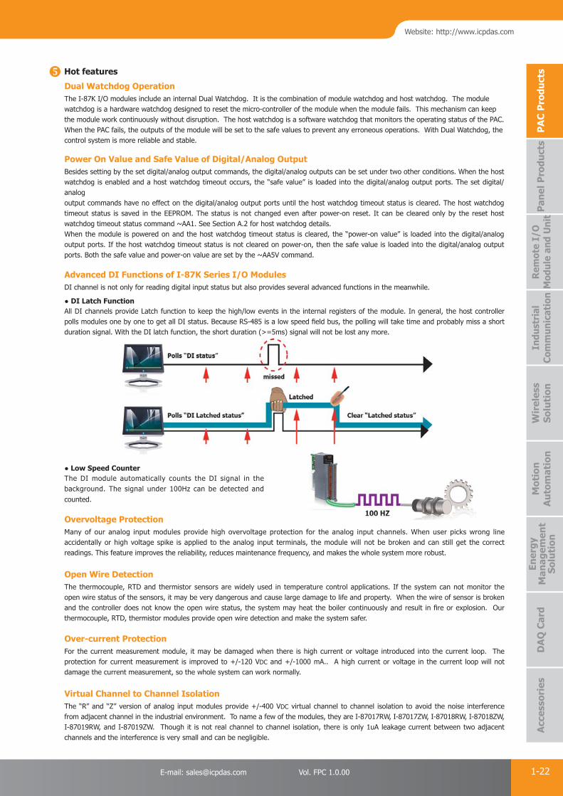
● DI Latch FunctionAll DI channels provide Latch function to keep the high/low events in the internal registers of the module. In general, the host controller polls modules one by one to get all DI status. Because RS-485 is a low speed fi eld bus, the polling will take time and probably miss a short duration signal. With the DI latch function, the short duration (>=5ms) signal will not be lost any more.
● Low Speed Counter The DI module automatically counts the DI signal in the background. The signal under 100Hz can be detected and counted.
Virtual Channel to Channel IsolationThe “R” and “Z” version of analog input modules provide +/-400 VDC virtual channel to channel isolation to avoid the noise interference from adjacent channel in the industrial environment. To name a few of the modules, they are I-87017RW, I-87017ZW, I-87018RW, I-87018ZW, I-87019RW, and I-87019ZW. Though it is not real channel to channel isolation, there is only 1uA leakage current between two adjacent channels and the interference is very small and can be negligible.
Over-current ProtectionFor the current measurement module, it may be damaged when there is high current or voltage introduced into the current loop. The protection for current measurement is improved to +/-120 VDC and +/-1000 mA.. A high current or voltage in the current loop will not damage the current measurement, so the whole system can work normally.
Open Wire DetectionThe thermocouple, RTD and thermistor sensors are widely used in temperature control applications. If the system can not monitor the open wire status of the sensors, it may be very dangerous and cause large damage to life and property. When the wire of sensor is broken and the controller does not know the open wire status, the system may heat the boiler continuously and result in fi re or explosion. Our thermocouple, RTD, thermistor modules provide open wire detection and make the system safer.

PAC Products
1-23 ICP DAS CO., LTD. Professional Provider of High Quality Industrial Computer Products and Data Acquisition Systems Vol. FPC 1.0.00
3000 VDC IsolationThe I-8K and I-87K series have 3000 VDC isolation between the fi eld and the internal logic. This isolation prevents the noise from the fi eld to the internal logic that can damage the module. It is recommended to choose isolated modules that will be plugged into controller. There will be no interference from the adjacent slot because the noise from the adjacent slot is isolated.
ESD ProtectionIn the industrial environment there are many noise, spike, electrostatic etc.. If the module is not strong enough, it is very easy to be damaged. The I-8KW and I-87KW modules all pass +/-4 KV ESD contact and +/- 8 KV ESD air tests by static electricity gun in our laboratory. The test procedures follow the IEC 61000-4-2 standard. Our modules are immunity to the electrostatic discharges by using components that can clamp and resist to the high voltages defi ned by IEC 61000-4-2 standard.
Common Voltage ProtectionThe typical application is to monitor the charging status of the batteries in series. The voltage of each battery is +10 VDC so the first battery is +10 VDC, the second battery i s +20 VDC etc . The differential voltage of the 20th battery is only +10 VDC between vin+ and vin- terminal, while the common voltage is up to 200 VDC. If the common voltage of the analog input module is not large enough, then it can not measure the correct voltage of the battery in charging. ICP DAS analog input modules provide +/-200 VDC high common voltage for industrial applications.
PAC Products
1-24E-mail: [email protected] Vol. FPC 1.0.00
Website: http://www.icpdas.com
PA
C P
rodu
cts
Pan
el P
rodu
cts
Rem
ote
I/O
M
odul
e an
d U
nit
DA
Q C
ard
Indu
stri
al
Com
mun
icat
ion
Wir
eles
s So
luti
onM
otio
n
Au
tom
atio
nA
cces
sori
esEn
ergy
M
anag
emen
tSo
luti
on
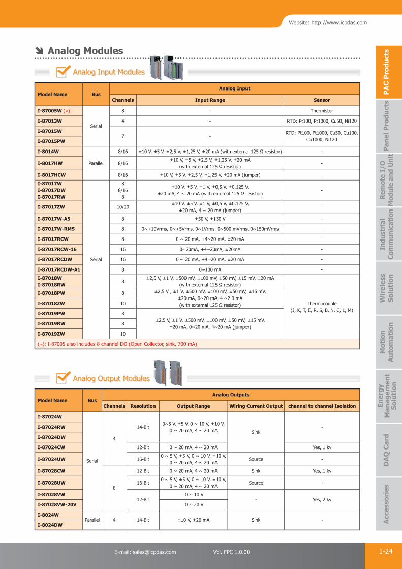
Model Name Bus Analog Input
Channels Input Range Sensor
I-87005W (*)
Serial
8 - Thermistor
I-87013W 4 - RTD: Pt100, Pt1000, Cu50, Ni120
I-87015W7 -
RTD: Pt100, Pt1000, Cu50, Cu100,Cu1000, Ni120I-87015PW
I-8014W
Parallel
8/16 ±10 V, ±5 V, ±2,5 V, ±1,25 V, ±20 mA (with external 125 Ω resistor) -
I-8017HW 8/16±10 V, ±5 V, ±2,5 V, ±1,25 V, ±20 mA
(with external 125 Ω resistor)-
I-8017HCW 8/16 ±10 V, ±5 V, ±2,5 V, ±1,25 V, ±20 mA (jumper) -
I-87017WI-87017DWI-87017RW
Serial
88/16
8
±10 V, ±5 V, ±1 V, ±0,5 V, ±0,125 V, ±20 mA, 4 ~ 20 mA (with external 125 Ω resistor)
-
I-87017ZW 10/20±10 V, ±5 V, ±1 V, ±0,5 V, ±0,125 V,
±20 mA, 4 ~ 20 mA (jumper)-
I-87017W-A5 8 ±50 V, ±150 V -
I-87017W-RMS 8 0~+10Vrms, 0~+5Vrms, 0~1Vrms, 0~500 mVrms, 0~150mVrms -
I-87017RCW 8 0 ~ 20 mA, +4~20 mA, ±20 mA -
I-87017RCW-16 16 0~20mA, +4~20mA, ±20mA -
I-87017RCDW 16 0 ~ 20 mA, +4~20 mA, ±20 mA -
I-87017RCDW-A1 8 0~100 mA -
I-87018WI-87018RW
8±2,5 V, ±1 V, ±500 mV, ±100 mV, ±50 mV, ±15 mV, ±20 mA
(with external 125 Ω resistor)
Thermocouple (J, K, T, E, R, S, B, N. C, L, M)
I-87018PW 8 ±2,5 V , ±1 V, ±500 mV, ±100 mV, ±50 mV, ±15 mV, ±20 mA, 0~20 mA, 4 ~2 0 mA (with external 125 Ω resistor)I-87018ZW 10
I-87019PW 8±2,5 V, ±1 V, ±500 mV, ±100 mV, ±50 mV, ±15 mV,
±20 mA, 0~20 mA, 4~20 mA (jumper)I-87019RW 8
I-87019ZW 10
(*): I-87005 also includes 8 channel DO (Open Collector, sink, 700 mA)
Model Name BusAnalog Outputs
Channels Resolution Output Range Wiring Current Output channel to channel Isolation
I-87024W
Serial
4
14-Bit0~5 V, ±5 V, 0 ~ 10 V, ±10 V,
0 ~ 20 mA, 4 ~ 20 mA Sink-I-87024RW
I-87024DW
I-87024CW 12-Bit 0 ~ 20 mA, 4 ~ 20 mA Yes, 1 kv
I-87024UW 16-Bit0 ~ 5 V, ±5 V, 0 ~ 10 V, ±10 V,
0 ~ 20 mA, 4 ~ 20 mASource -
I-87028CW
8
12-Bit 0 ~ 20 mA, 4 ~ 20 mA Sink Yes, 1 kv
I-87028UW 16-Bit0 ~ 5 V, ±5 V, 0 ~ 10 V, ±10 V,
0 ~ 20 mA, 4 ~ 20 mASource -
I-87028VW12-Bit
0 ~ 10 V- Yes, 2 kv
I-87028VW-20V 0 ~ 20 V
I-8024WParallel 4 14-Bit ±10 V, ±20 mA Sink -
I-8024DW
Analog Input Modules
Analog Output Modules
Analog Modules
PAC Products
1-25 ICP DAS CO., LTD. Professional Provider of High Quality Industrial Computer Products and Data Acquisition Systems Vol. FPC 1.0.00
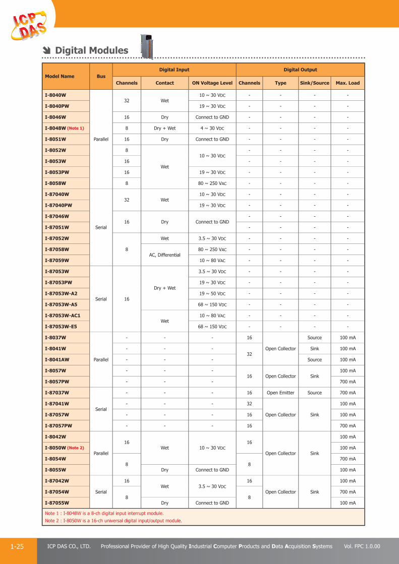
Model Name BusDigital Input Digital Output
Channels Contact ON Voltage Level Channels Type Sink/Source Max. Load
I-8040W
Parallel
32 Wet10 ~ 30 VDC - - - -
I-8040PW 19 ~ 30 VDC - - - -
I-8046W 16 Dry Connect to GND - - - -
I-8048W (Note 1) 8 Dry + Wet 4 ~ 30 VDC - - - -
I-8051W 16 Dry Connect to GND - - - -
I-8052W 8
Wet
10 ~ 30 VDC- - - -
I-8053W 16 - - - -
I-8053PW 16 19 ~ 30 VDC - - - -
I-8058W 8 80 ~ 250 VAC - - - -
I-87040W
Serial
32 Wet10 ~ 30 VDC - - - -
I-87040PW 19 ~ 30 VDC - - - -
I-87046W16 Dry Connect to GND
- - - -
I-87051W - - - -
I-87052W
8
Wet 3.5 ~ 30 VDC - - - -
I-87058WAC, Differential
80 ~ 250 VAC - - - -
I-87059W 10 ~ 80 VAC - - - -
I-87053W
Serial 16
Dry + Wet
3.5 ~ 30 VDC - - - -
I-87053PW 19 ~ 30 VDC - - - -
I-87053W-A2 19 ~ 50 VDC - - - -
I-87053W-A5 68 ~ 150 VDC - - - -
I-87053W-AC1Wet
10 ~ 80 VAC - - - -
I-87053W-E5 68 ~ 150 VDC - - - -
I-8037W
Parallel
- - - 16
Open Collector
Source 100 mA
I-8041W - - -32
Sink 100 mA
I-8041AW - - - Source 100 mA
I-8057W - - -16 Open Collector Sink
100 mA
I-8057PW - - - 700 mA
I-87037W
Serial
- - - 16 Open Emitter Source 700 mA
I-87041W - - - 32
Open Collector Sink
100 mA
I-87057W - - - 16 100 mA
I-87057PW - - - 16 700 mA
I-8042W
Parallel
16Wet 10 ~ 30 VDC
16
Open Collector Sink
100 mA
I-8050W (Note 2) 100 mA
I-8054W8 8
700 mA
I-8055W Dry Connect to GND 100 mA
I-87042W
Serial
16Wet 3.5 ~ 30 VDC
16
Open Collector Sink
100 mA
I-87054W8 8
700 mA
I-87055W Dry Connect to GND 100 mA
Note 1 : I-8048W is a 8-ch digital input interrupt module.
Note 2 : I-8050W is a 16-ch universal digital input/output module.
Digital Modules

PAC Products
1-26E-mail: [email protected] Vol. FPC 1.0.00
Website: http://www.icpdas.com
PA
C P
rodu
cts
Pan
el P
rodu
cts
Rem
ote
I/O
M
odul
e an
d U
nit
DA
Q C
ard
Indu
stri
al
Com
mun
icat
ion
Wir
eles
s So
luti
onM
otio
n
Au
tom
atio
nA
cces
sori
esEn
ergy
M
anag
emen
tSo
luti
on
Model Name Bus Channels Type Contact Load Current
I-8060W
Parallel
6 Power Relay Form C 0.5 A @ 125 VAC, 0.25 A @ 250 VAC, 2 A @ 30 VDC
I-8063W (*) 4 Power Relay Form CForm A: 5 A @ 250 VAC/30 VDC
Form C: 3 A @ 250 VAC/30 VDC
I-8064W 8 Power Relay Form A 5 A @ 250 VAC, 5 A @ 30 VDC
I-8068W 8 Power RelayForm A x 4Form C x 4
Form A: 5 A @ 250 VAC/30 VDC
Form C: 3 A @ 250 VAC/30 VDC
I-8069W 8 PhotoMOS Form A 1 A @ 60 VDC
I-87061W
Serial
16 Power Relay Form A 5.0 A @ 250 VAC/30 VDC
I-87063W (*) 4 Power Relay Form CForm A: 5 A @ 250 VAC/30 VDC
Form C: 3 A @ 250 VAC/30 VDC
I-87064W 8 Power Relay Form A 5.0 A @ 250 VAC/30 VDC
I-87065W 8 AC SSR Form A 1.0 A @ 265 VAC
I-87066W 8 DC SSR Form A 1.0 A @ 30 VDC
I-87068W 8 Power RelayForm A x 4Form C x 4
Form A: 8 A @ 250 VAC/30 VDC
Form C: 3 A @ 250 VAC/30 VDC
I-87069W 8 PhotoMOS Form A 0.13 A, 350 V Max. at DC/AC
I-87069PW 8 PhotoMOS Form A 1.0 A, 80 V Max. at DC/AC
(*): I-8063W and I-87063W also have 4 DI (Wet contact, sink and source)
Multi-Function/Strain Gauge Modules
Model Name Bus Analog Inputs Analog Outputs Digital Inputs Digital Outputs
I-87016W Serial2 (Strain Gauges)
(Full-bridge, Half-bridge, Quarter-bridge) 2(Voltage, Current)
2(Wet, Sink)
2(Open Collector, Sink)I-87026PW Serial 6
(Voltage, Current)I-8026W Parallel
Counter/Frequency/PWM Modules
Relay Modules
Model Name BusCounter/Frequency Input PWM Output
Channels Counter Signal SpeedFrequency Accuracy
Channels Type
I-87082W Serial 2 32-bit Up 100 kHz 1 Hz 2 Open Collector
I-8084W Parallel4/8 32-bit
Up, CW/CCW,
A/B, Pulse/Dir250 kHz 0.1 Hz
- -
I-87084W Serial - -
I-8088W Parallel - - - -- 8 PWM
Duty: 0.1 ~ 99.9%
I-87088W Serial 8 32-bit Up 1 MHz Freq: 1 ~ 500 KHz
PAC Products
1-27 ICP DAS CO., LTD. Professional Provider of High Quality Industrial Computer Products and Data Acquisition Systems Vol. FPC 1.0.00
Serial Communication Modules
CAN/CANopen/DeviceNet Master Modules
Model Name Bus Ports Type Isolation Connector Accessories
I-8112iW
Parallel
2
RS-232
2500 Vrms 2 x D-Sub9 CA-0915
I-8114W 4 -D-Sub 37 CA-9-3705
I-8114iW 4
2500 VrmsI-8142iW 2RS-232/485 Terminal Block -
I-8144iW 4
CA-0915 CA-9-3705
Model Name Bus Ports Max Speed Protocol
I-8120WParallel
1
1 Mbps
CAN 2.0A/2.0B
I-8123WCANopen
I-87123W Serial
I-8124W Parallel500 Kbps DeviceNet
I-87124W Serial
Motion Control Modules
Model Name
Encoder Input Command Pulse OutputDaughter
BoardOther
FunctionsAxis CounterInput Rate
(pps)Signal Axis
Speed(pps)
Counter Signal
I-8092F 2 32-bit 1 M CW/CCW, A/B 2 4 M 32-bit CW/CCW, PULSE/DIR DN-8237 FRnet Master
I-8093W 3 32-bit 1 MCW/CCW, A/B,
Pulse/Dir- - - - - -
I-8094 4 32-bit 1 M CW/CCW, A/B 4 4 M 32-bit CW/CCW, PULSE/DIR DN-8468 -
I-8094F 4 32-bit 1 M CW/CCW, A/B 4 4 M 32-bit CW/CCW, PULSE/DIR DN-8468 FRnet Master
Daughter-Board for two-axis motion controller
DN-8237GB: for general purpose usage
DN-8237MB: for Mitsubishi servo J2 Amplifi er
DN-8237PB: for Panasonic servo minas A Amplifi er
DN-8237YB: for Yaskawa servo Amplifi er
DN-8237DB: for Delta ASDA A servo Amplifi er
DN-8237 Series
Dimensions: 110 mm X 107 mm
Daughter-Board for four-axis motion controller
DN-8468GB: for general purpose usage
DN-8468MB: for Mitsubishi servo J2 Amplifi er
DN-8468PB: for Panasonic servo minas A Amplifi er
DN-8468YB: for Yaskawa servo Amplifi er
DN-8468DB: for Delta ASDA A servo Amplifi er
DN-8468FB: for FUJI FALDIC-W servo Amplifi er
DN-8468 Series
Dimensions: 162 mm X 107 mm

PAC Products
1-28E-mail: [email protected] Vol. FPC 1.0.00
Website: http://www.icpdas.com
PA
C P
rodu
cts
Pan
el P
rodu
cts
Rem
ote
I/O
M
odul
e an
d U
nit
DA
Q C
ard
Indu
stri
al
Com
mun
icat
ion
Wir
eles
s So
luti
onM
otio
n
Au
tom
atio
nA
cces
sori
esEn
ergy
M
anag
emen
tSo
luti
on
FRnet Communication Modules (Parallel Bus)
2G/3G/GPS Modules
HART Communication Modules
Model Name Frequency (MHz) GPS Interface Max. Download Speed AT Command TCP/IP Protocol
I-8212W-3GWA2G (GSM/GPRS): 850/900/1800/1900
- 9.6 ~ 115.2 Kbps Yes Yes3G (UMTS/HSDPA/HSUPA): 2100/1900/850
I-8213W-3GWA2G (GSM/GPRS): 850/900/1800/1900
Yes 9.6 ~ 115.2 Kbps Yes Yes3G (UMTS/HSDPA/HSUPA): 2100/1900/850
Model Name GPS
ChannelsSBAS
GPS OutputInterface
GSM/GPRSDigital Output
Protocol/Interface
Description
I-87211W 32 WAAS, EGNOS, MSAS RS-232 - 2 DCON GPS Receiver and 2 DO Module
Model Name Description
I-87H17W HART Module with 8-ch analog inputs
I-87H24W HART Module with 4-ch analog outputs
FR-2000 Series I/O Modules
FR-2054T FR-2057iT FR-2053iT FR-2017iT
FR I/O BoardsFR I/O
FR-32R
Boards
FR-32P
Speed Baudrate Max. Distance Fixed Cycle Time
High Speed 1 Mbps 100 m 0.72 ms
Low Speed (Default) 250 kbps 400 m 2.88 ms
Easy connection: multi-drop networking with twisted pair cable Easy programming: memory mapping (no communication protocol needed) I/O expansion ability for each port: 8 SA nodes (for DI) and 8 RA nodes (for DO), each node addresses to 16 DI or DO channels Normally FRnet module provides two communication speeds. OEM customer can call manufacturer to design special FRnet module for long distance communication.
FRnet Bus I/O
I-8172W/FRnet Communication Module
I-8172W
I-8172W Features
Applications
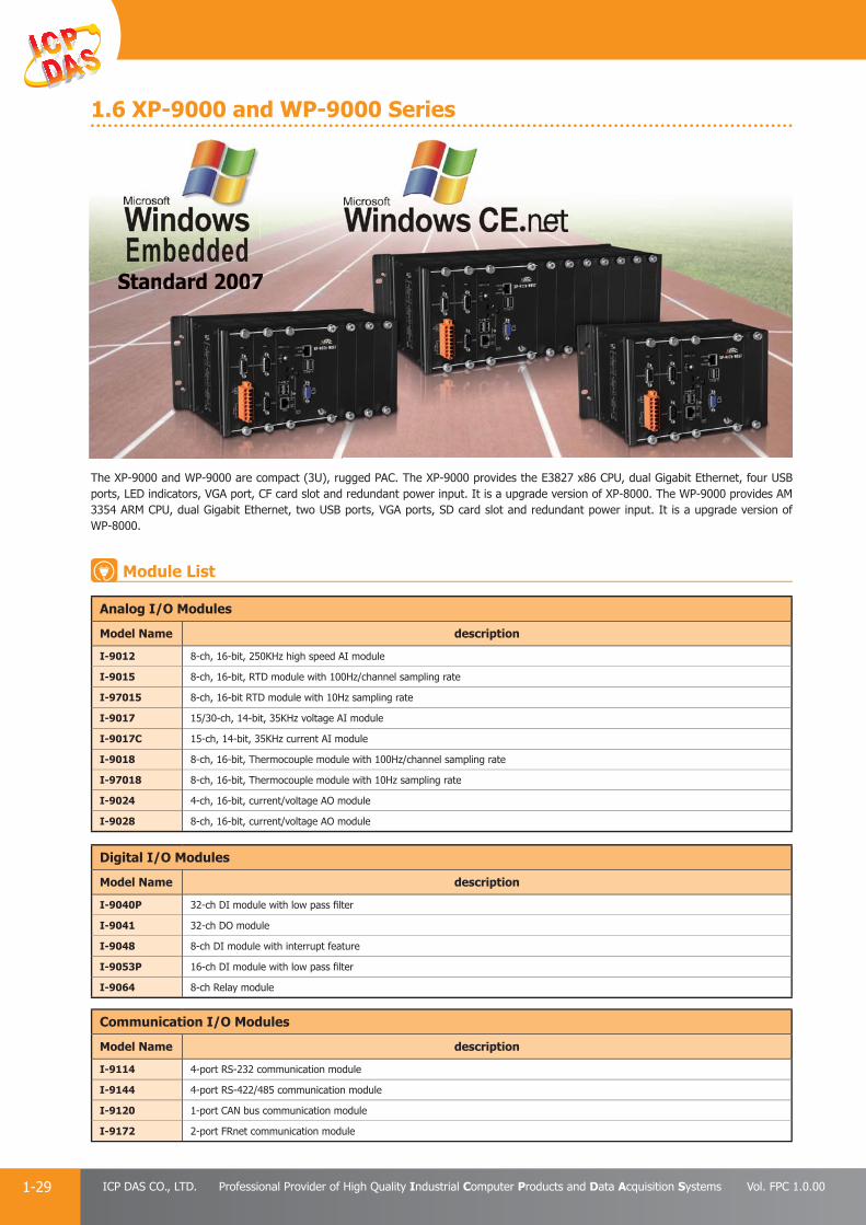
PAC Products
1-29 ICP DAS CO., LTD. Professional Provider of High Quality Industrial Computer Products and Data Acquisition Systems Vol. FPC 1.0.00
1.6 XP-9000 and WP-9000 Series
The XP-9000 and WP-9000 are compact (3U), rugged PAC. The XP-9000 provides the E3827 x86 CPU, dual Gigabit Ethernet, four USB ports, LED indicators, VGA port, CF card slot and redundant power input. It is a upgrade version of XP-8000. The WP-9000 provides AM 3354 ARM CPU, dual Gigabit Ethernet, two USB ports, VGA ports, SD card slot and redundant power input. It is a upgrade version of WP-8000.
Standard 2007
Module List
Analog I/O Modules
Model Name description
I-9012 8-ch, 16-bit, 250KHz high speed AI module
I-9015 8-ch, 16-bit, RTD module with 100Hz/channel sampling rate
I-97015 8-ch, 16-bit RTD module with 10Hz sampling rate
I-9017 15/30-ch, 14-bit, 35KHz voltage AI module
I-9017C 15-ch, 14-bit, 35KHz current AI module
I-9018 8-ch, 16-bit, Thermocouple module with 100Hz/channel sampling rate
I-97018 8-ch, 16-bit, Thermocouple module with 10Hz sampling rate
I-9024 4-ch, 16-bit, current/voltage AO module
I-9028 8-ch, 16-bit, current/voltage AO module
Digital I/O Modules
Model Name description
I-9040P 32-ch DI module with low pass fi lter
I-9041 32-ch DO module
I-9048 8-ch DI module with interrupt feature
I-9053P 16-ch DI module with low pass fi lter
I-9064 8-ch Relay module
Communication I/O Modules
Model Name description
I-9114 4-port RS-232 communication module
I-9144 4-port RS-422/485 communication module
I-9120 1-port CAN bus communication module
I-9172 2-port FRnet communication module
SSSSSSSSSSSSSSSSSSSSSSSSSSSSSSttttttaaaaaaaaaaaannnnnnnnnnnnnnnnnnnnnnnnnnnnnnnnnnndddddddddddddddddddddddddddddddaaaaaaaaaaaaaaaaaaaaaaaaaaaaaaaarrrrdddddddddddddddd 2222200000000000000000000000000000000000000000000000000000000000007777777777777777777777777777777777
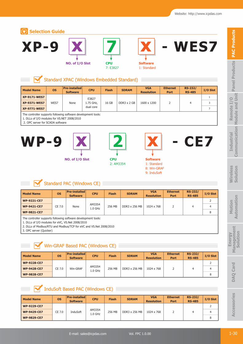
PAC Products
1-30E-mail: [email protected] Vol. FPC 1.0.00
Website: http://www.icpdas.com
PA
C P
rodu
cts
Pan
el P
rodu
cts
Rem
ote
I/O
M
odul
e an
d U
nit
DA
Q C
ard
Indu
stri
al
Com
mun
icat
ion
Wir
eles
s So
luti
onM
otio
n
Au
tom
atio
nA
cces
sori
esEn
ergy
M
anag
emen
tSo
luti
on
XP-9 xNO. of I/O Slot
xSoftware1: Standard
7CPU7: E3827
- WES7Selection Guide
WP-9 x xNO. of I/O Slot Software
1: Standard8: Win-GRAF9: InduSoft
CPU2: AM3354
- CE72
Model Name OSPre-installed
SoftwareCPU Flash SDRAM
VGA Resolution
Ethernet Port
RS-232/RS-485
I/O Slot
XP-9171-WES7
WES7 NoneE3827
1.75 GHz, dual core
16 GB DDR3 x 2 GB 1600 x 1200 2 4
1
XP-9371-WES7 3
XP-9771-WES7 7
The controller supports following software development tools:1. DLLs of I/O modules for VS.NET 2008/2010 2. OPC server for SCADA software
Standard XPAC (Windows Embedded Standard)
Model Name OSPre-installed
SoftwareCPU Flash SDRAM
VGA Resolution
Ethernet Port
RS-232/RS-485
I/O Slot
WP-9221-CE7
CE 7.0 NoneAM33541.0 GHz
256 MB DDR3 x 256 MB 1024 x 768 2 4
2
WP-9421-CE7 4
WP-9821-CE7 8
The controller supports following software development tools:1. DLLs of I/O modules for eVC, VS.Net 2008/2010 2. DLLs of Modbus/RTU and Modbus/TCP for eVC and VS.Net 2008/2010 3. OPC server (Quicker)
Model Name OSPre-installed
SoftwareCPU Flash SDRAM
VGA Resolution
Ethernet Port
RS-232/RS-485
I/O Slot
WP-9229-CE7
CE 7.0 InduSoftAM33541.0 GHz
256 MB DDR3 x 256 MB 1024 x 768 2 4
2
WP-9429-CE7 4
WP-9829-CE7 8
Model Name OSPre-installed
SoftwareCPU Flash SDRAM
VGA Resolution
Ethernet Port
RS-232/RS-485
I/O Slot
WP-9228-CE7
CE 7.0 Win-GRAFAM33541.0 GHz
256 MB DDR3 x 256 MB 1024 x 768 2 4
2
WP-9428-CE7 4
WP-9828-CE7 8
Standard PAC (Windows CE)
InduSoft Based PAC (Windows CE)
Win-GRAF Based PAC (Windows CE)

PAC Products
1-31 ICP DAS CO., LTD. Professional Provider of High Quality Industrial Computer Products and Data Acquisition Systems Vol. FPC 1.0.00
2. 7188/7186 Series μPAC
ICP DAS develops a family of palm-size PAC named μPAC (micro Programmable Automation Controller). Featuring robust, powerful, space-saving, cost-effective and more, μPAC presents excellent performance in various Industry Automation applications in the challenging environments.
I-7188 — the 1st generation“I-7188 Series”, the fi rst generation of μPAC, has been widely used in various Industry Automation applications. It is characterized by fast-booting operating system MiniOS7, interchangeable X-Board for function expansion, fl exible COM port confi guration and user-defi ned I/O pins.
μPAC-7186 — the 2nd generation“μPAC-7186 Series”, debuting in 2008, further improves and upgraded features, such as faster CPU, better 10/100 Base-TX Ethernet port, lower power consumption and diversifi ed Memory combination selections. With better performance, it is suitable for more sophisticated applications: auto-reporting data acquisition, M2M automation system, wire/wireless remote control, data logger application, redundant solution.
Generation CPU Ethernet Memory Expansion Power consumption
I-7188 Series 40 MHz 10 BaseT SRAM, Flash 2 W
μPAC-7186 80 MHz 10/100 BaseTX SRAM, Flash 1.5 W
● Top 10 reasons to choose μPAC by ICP DAS
Powerful Embedded OS — MiniOS7MiniOS7 is the most stable OS used in the last decade. Up to now, several hundred thousand copies with our PACs have been distributed worldwide.
Features:• DOS-like embedded OS
• Antivirus ability
• Internet connectivity
• Libraries & demo programs for various peripherals, devices and remote I/O modules
Rich Development SupportWe provide over 100 Libraries and Demos for users to develop applications easily and quickly to integrate with some popular software, SCADA, protocols or tools.
• Provide Libraries: Xserver, Modbus, MiniOS7 Framework• Support development tool: ISaGRAF, C Language
Patented Technology: “Self-Tuner” ChipOur μPAC contains a patented "Self-tuner" chip which automatically tunes Baud rate and data format in the whole RS-485 network. It also handles the direction of RS-485 communication line.
Unique 64-bit Hardware Serial Number Protecting Your ProgramAll μPAC-7186 series and most I-7188 series come with a 64-bit unique hardware serial number. A unique serial number is assigned to each hardware device to protect your software against piracy.
Built-in RTC — Real Time Clock• Provides second, minute, hour, day of week, day of month, month & year (1980 ~ 2079)• With on-board battery• Data valid up to 10 years• Keep accurate time/date while the main power is lost
• Short boot time period (<1 Second)
• Less memory resource required
• Faster watchdog response time
● Introduction
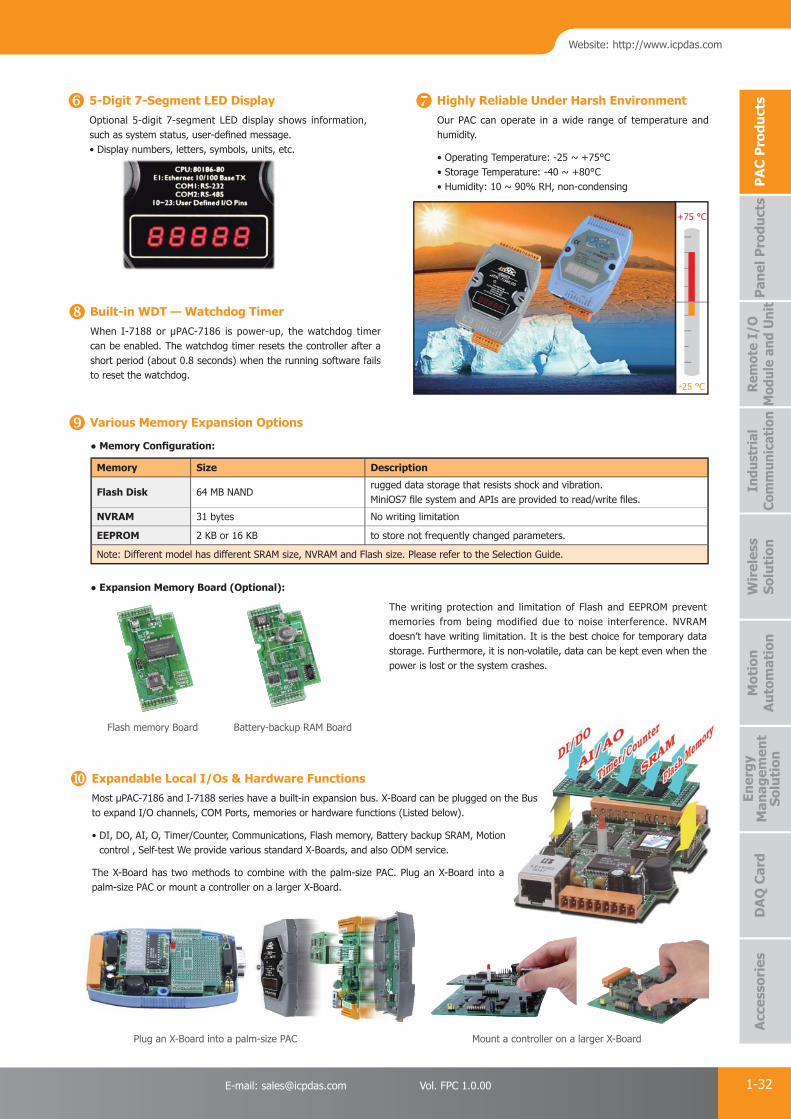
PAC Products
1-32E-mail: [email protected] Vol. FPC 1.0.00
Website: http://www.icpdas.com
PA
C P
rodu
cts
Pan
el P
rodu
cts
Rem
ote
I/O
M
odul
e an
d U
nit
DA
Q C
ard
Indu
stri
al
Com
mun
icat
ion
Wir
eles
s So
luti
onM
otio
n
Au
tom
atio
nA
cces
sori
esEn
ergy
M
anag
emen
tSo
luti
on
5-Digit 7-Segment LED DisplayOptional 5-digit 7-segment LED display shows information, such as system status, user-defi ned message.• Display numbers, letters, symbols, units, etc.
Highly Reliable Under Harsh EnvironmentOur PAC can operate in a wide range of temperature and humidity.
• Operating Temperature: -25 ~ +75°C• Storage Temperature: -40 ~ +80°C• Humidity: 10 ~ 90% RH, non-condensing
Built-in WDT — Watchdog TimerWhen I-7188 or μPAC-7186 is power-up, the watchdog timer can be enabled. The watchdog timer resets the controller after a short period (about 0.8 seconds) when the running software fails to reset the watchdog.
Memory Size Description
Flash Disk 64 MB NANDrugged data storage that resists shock and vibration.MiniOS7 fi le system and APIs are provided to read/write fi les.
NVRAM 31 bytes No writing limitation
EEPROM 2 KB or 16 KB to store not frequently changed parameters.
Note: Different model has different SRAM size, NVRAM and Flash size. Please refer to the Selection Guide.
Various Memory Expansion Options
● Memory Confi guration:
● Expansion Memory Board (Optional):
Flash memory Board Battery-backup RAM Board
The writing protection and limitation of Flash and EEPROM prevent memories from being modified due to noise interference. NVRAM doesn’t have writing limitation. It is the best choice for temporary data storage. Furthermore, it is non-volatile, data can be kept even when the power is lost or the system crashes.
Expandable Local I/Os & Hardware FunctionsMost μPAC-7186 and I-7188 series have a built-in expansion bus. X-Board can be plugged on the Bus to expand I/O channels, COM Ports, memories or hardware functions (Listed below).
• DI, DO, AI, O, Timer/Counter, Communications, Flash memory, Battery backup SRAM, Motion control , Self-test We provide various standard X-Boards, and also ODM service.
The X-Board has two methods to combine with the palm-size PAC. Plug an X-Board into a palm-size PAC or mount a controller on a larger X-Board.
Plug an X-Board into a palm-size PAC Mount a controller on a larger X-Board
+75 °C
-25 °C

PAC Products
1-33 ICP DAS CO., LTD. Professional Provider of High Quality Industrial Computer Products and Data Acquisition Systems Vol. FPC 1.0.00
μPAC-7186 -E x x xxLED DisplayD: With 5-digit
7-segment LED Display
SoftwareX: C language based
G: ISaGRAF
Special FeatureSM: 640 KB SRAM
FD: 64 MB NAND Flash
I-7188 x x xEthernet Port- : Without I/O Expansion Bus & Ethernet Port
E: With Ethernet Port
X: Without Ethernet Port
LED DisplayD: With 5-digit
7-segment
LED Display
Software & Communication PortsA: C language based (2-DI , 2-DO, RS-232 and RS-485)
B: C language based (1-DI , 1-DO, RS-232 and RS-485)
C: C language based (2-DI , 3-DO, RS-232 and RS-485)
X: C language based (RS-232 and RS-485)
G: ISaGRAF
Serial Connectivity
Model Name CPU SRAM Flash I/O Expansion Bus64-bit HardwareSerial Number
RTC DI DO RS-232/RS-485
I-7188I-7188D
40 MHz
256 KB
512 KB
- -
Yes
- -4
(Note)I-7188XAI-7188XAD
512 KB
For memoryboard only
Yes
2 2
I-7188XBI-7188XBD
Yes 1 1
1/1I-7188XCI-7188XCD
20 MHz 128 KB Yes - - 2 3
Note: RS-232 × 2, RS-485 × 1, RS-232/485 × 1
C Language Based I-7188 and μPAC-7186
Model Name CPU SRAM Flash NAND FlashI/O Expansion
BusRTC DI DO Ethernet RS-232/RS-485
I-7188EAI-7188EAD
40 MHz 512 KB 512 KB -
-
Yes
6 7
10 Base-T 1/1I-7188EXI-7188EXD
Yes - -
μPAC-7186EXμPAC-7186EXD
80 MHz
512 KB
512 KB
-
Yes Yes10/100 Base-
Tx1/1
μPAC-7186EX-SMμPAC-7186EXD-SM
640 KB
μPAC-7186EX-FDμPAC-7186EXD-FD
512 KB 64 MB
Model Name CPU SRAM Flash I/O Expansion Bus RTC DI DO Ethernet RS-232/RS-485
μPAC-7186EGμPAC-7186EGD
80 MHz 768 KB
512 KB Yes Yes
- - 10/100 Base-TX 1/1
I-7188XGI-7188XGD
40 MHz 512 KB 1 1 - 1/1
ISaGRAF Based μPAC-7186 & I-7188
Selection Guide

PAC Products
1-34E-mail: [email protected] Vol. FPC 1.0.00
Website: http://www.icpdas.com
PA
C P
rodu
cts
Pan
el P
rodu
cts
Rem
ote
I/O
M
odul
e an
d U
nit
DA
Q C
ard
Indu
stri
al
Com
mun
icat
ion
Wir
eles
s So
luti
onM
otio
n
Au
tom
atio
nA
cces
sori
esEn
ergy
M
anag
emen
tSo
luti
on
2.1 I/O Expansion Boards for 7188/7186 Series
X-Board is a small I/O expansion board inserted in μPAC (μPAC-7186 Series & I-7188 series) for expanding I/O functions. Most μPACs (except some modules like I-7188 & I-7188D) support one I/O expansion bus. Each bus can be plugged in one X-Board. The X-Board allows users to implement various I/O functions such as DI, DO, A/D, D/A, Timer/Counter, UART, fl ash memory, battery backup SRAM, AsicKey & other I/O functions.
Users may choose our functioned X-Boards (model number X1xx ~ X7xx) or design their own I/O expansion boards (module number X0xx). We have designed several X-Boards for expanding the μPAC's features. If users choose a small size X-Board, then they can mount this I/O expansion board directly onto the μPAC. Customized I/O Expansion Boards can be ordered through ODM project.
X-Board is Series has following common specifi cations● DI channel: Dry contact, sink type, non-isolated● DO channel: Open Collector, sink type, 100 mA/channel load current, non-isolated
Following μPAC supports I/O Expansion Bus, can mount one X-Board● For C language solution: I-7188XB(D), I-7188EX(D),
μPAC-7186EX(D), μPAC-7186PEX(D),μPAC-7186EX(D)-FD, μPAC-7186EX(D)-SM
● For ISaGRAF solution: I-7188XG(D), μPAC-7186EG(D)
Model Name DI
(Dry Contact)DO
(Open Collector)
X107 6 7
X110 14 -
X111 - 13
Model Name AI (12-bit) AO (12-bit) DI
(Dry Contact)DO
(Open Collector)Channel Range Channel Range
X202 7 0 ~ 20 mA - - - -
X203 2 0 ~ 20 mA - - 2 6
X303 1 +/-5 VDC 1 +/-5 VDC 4 6
X304 3 +/-5 VDC 1 +/-5 VDC 4 4
X305 7 +/-5 VDC 1 +/-5 VDC 2 2
X308 4 0 ~ 10 VDC - - - 6
X310 20 ~ 20 mA0 ~ 10 VDC
2 0 ~ 10 VDC 3 3
X324 - - 4 0 ~ 5 VDC - 4
DI, DO Expansion
AI, AO, DI, DO Expansion
Introduction
Selection Guide

PAC Products
1-35 ICP DAS CO., LTD. Professional Provider of High Quality Industrial Computer Products and Data Acquisition Systems Vol. FPC 1.0.00
Model Name Serial Port DI
(Dry Contact)DO
(Open Collector)EEPROM
Type Channel Wire
X503 RS-232 1 5 Wire
- -
-
X504 RS-232 2 5 Wire and 9 Wire
X505 RS-232 3 5 Wire
X506 RS-232 6 3 Wire
X507 RS-422/485 1 4/2 Wire 4 4
X508 RS-232 1 5 Wire 4 4
X509 RS-232 2 3 Wire 4 4
X510 RS-232 1 3 Wire 5 5 256 KB
X510-128 RS-232 1 3 Wire 5 5 128 KB
X511 RS-485 3 2 Wire - -
-X518 RS-232 1 5 Wire - 8
X520 RS-232 4 3 Wire 1 2
RS-232/422/485, DI, DO Expansion
Model Name Memory Type Size Data Retention Endurance
X603 NAND Flash 256 MB 10 years 100,000 erase cycles
X607Battery Backup SRAM
128 KB9 years No erase cycle limitation
X608 512 KB
Model Name Axis Counter Mode Max. Speed5V Input
Level12V Input Level
(with 1 KΩ external resistors)
24V Input Level(with 2 KΩ external resistors)
X702 232-bit
Quadrant, CW/CCW,
Pulse/Direction1 MHz
3.5 ~ 5 V0 ~ 2 V
5 ~ 12 V0 ~ 2 V
7 ~ 24 V0 ~ 2 VX703 3
Note: ISaGRAF doesn't support X702 and X703.
Memory Expansion
Encoder Expansion
7188XC only
Model Name DI
(Dry Contact)DO
(Open Collector)
AI (12-bit) AO (12-bit)
Channel Range Channel Range
X101 - 8 - - - -
X106 DI × 3 or DO × 2 - - - -
X200 - - 1 0 ~ 2.5 VDC - -
X302 - - 1 +/-5 VDC 1 +/-5 VDC

PAC Products
1-36E-mail: [email protected] Vol. FPC 1.0.00
Website: http://www.icpdas.com
PA
C P
rodu
cts
Pan
el P
rodu
cts
Rem
ote
I/O
M
odul
e an
d U
nit
DA
Q C
ard
Indu
stri
al
Com
mun
icat
ion
Wir
eles
s So
luti
onM
otio
n
Au
tom
atio
nA
cces
sori
esEn
ergy
M
anag
emen
tSo
luti
on
3. 5000 Series μPAC3.1 μPAC-5000 Series
Remote I/O Module and Expansion UnitWith the built-in RS-485 and Ethernet ports, the 5000 series can connect RS-485/Ethernet remote I/O units (RU-87Pn/ET-87Pn) or modules (I-7000/M-7000/ET-7000). With an XW-Board, the 5000 series can have more communication ports or different interface to connect to other type of devices, for example, CANOpen devices, DeviceNet devices, or FRnet I/O modules.
MiniOS780186 CPUμPAC-5000 Series
MiniOS7 Inside
Local I/O and Communication Expansion BoardThe μPAC 5000 series is equipped with an I/O expansion bus to support one optional expansion board, called XW-Board. It can be used to implement various I/O functions such as DI, DO, A/D, D/A, Timer/Counter and various communication interface options, such as RS-232/422/485, CAN, FRnet.
The μPAC-5000 Series is equipped a 80186 CPU running a MiniOS7 operating system, a variety of connectivity options (Ethernet, RS-232/485) and an I/O expansion bus.
The μPAC-5000 series is an enhanced version of μPAC-7186. Owing to the bigger and special form factor design, the μPAC-5000 can add an internal wireless module, such as 2G, 3G, Wi-Fi, GPS for different wireless application. The optional I/O expansion board, XW-board, is two times larger than the X-board of μPAC-7186 and provides high-protection I/O. With built-in micro SD, the μPAC-5000 can be used as a data logger.
DOS-like real-time OS Boot up in 0.4 ~ 0.8 second Built-in hardware diagnostic Standard version for C language programming ISaGRAF version for IEC 61131-3 programming
Features

PAC Products
1-37 ICP DAS CO., LTD. Professional Provider of High Quality Industrial Computer Products and Data Acquisition Systems Vol. FPC 1.0.00
M-7000I-7000RU-87Pn
Remote I/O
FR-2054TFR-2057iTFR-2053iT
RS-485RS-485
EthernetEthernet
FRnetFRnet
CAN busCAN bus
CAN-8000 Series CAN-2000 Series
CAN-2088CCAN-2018CCAN-8224 CAN-8424CAN-8124
ET-87Pn ET-7000
R 22222222222222000057i57i05 ii00 7i77i RR 222222R 2R 2R 22222R 22R 2R 2R 222RR 22200000005555405500R 22222200505053053300
RURURURURRURU 8RURU 87P7Pnn
CACAAAANANANANNNNNNNNNNNNNNAN 82288282888822282282222882882222282828228282228 CANCANCAANCAN-NCANANCAN-ANCAN--842488424484224842448424
ETEETTTTET 8ET-88T 8TETT 8ET-8ETTEEEET-8ET-8E 77Pn7Pn
Multiple Communication InterfacesSeveral different types of communication interface are available that enable I/O modules to be expanded and connected to external devices:
1. Ethernet 2. RS-232/485 3. CAN bus 4. FRnet 5. GPS 6. 2G/3G 7. Wi-Fi
Various Memory Storage OptionsμPAC-5000 provides various memory storage options. Customers can choose the memory based on their characteristics.
16 KB EEPROM: to store not frequently changed parameters. microSD: to implement portable data logging applications. 256 MB NAND Flash Disk: rugged data storage to resist shock and vibration.
Unique 64-bit Hardware Serial Number to Protect Your ProgramA unique 64-bit serial number is assigned to each hardware device to protect your software against piracy.
Plastic and Metal CasingThe default case is plastic material. Metal casing is also offered to OEM version.
Redundant Power Inputs Highly Reliable Under Harsh Environment
Our μPACs operate in a wide range of temperature and humidity.
• Operating Temperature: -25 ~ +75°C
• Storage Temperature: -30 ~ +80°C
• Humidity 10 ~ 90% RH (non-condensing)
GPS
2G/3G
PC Cell Phone
Internet
-25°C
+75°C
T 7T 7000000
Power1 Power2
5000 Series
based on tn tn tttheihhh r characteristic
Plastic CasingMetal Casing
mre
μPAC-5000 + XW-Board
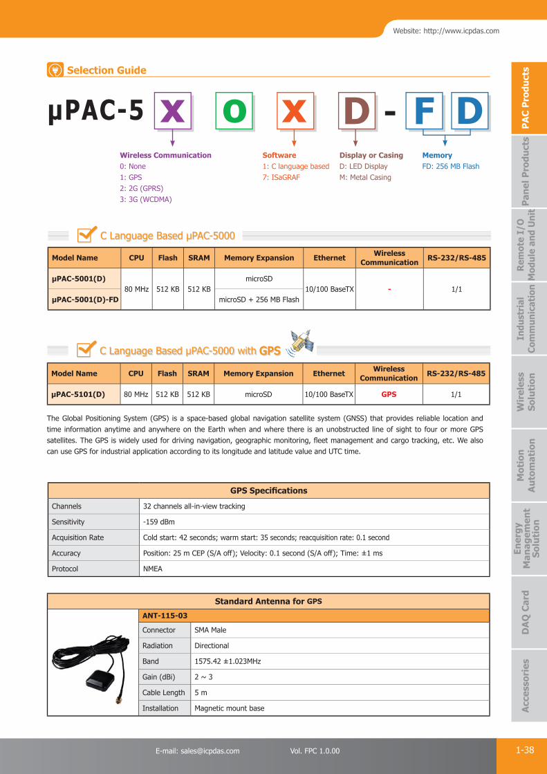
PAC Products
1-38E-mail: [email protected] Vol. FPC 1.0.00
Website: http://www.icpdas.com
PA
C P
rodu
cts
Pan
el P
rodu
cts
Rem
ote
I/O
M
odul
e an
d U
nit
DA
Q C
ard
Indu
stri
al
Com
mun
icat
ion
Wir
eles
s So
luti
onM
otio
n
Au
tom
atio
nA
cces
sori
esEn
ergy
M
anag
emen
tSo
luti
on
The Global Positioning System (GPS) is a space-based global navigation satellite system (GNSS) that provides reliable location and time information anytime and anywhere on the Earth when and where there is an unobstructed line of sight to four or more GPS satellites. The GPS is widely used for driving navigation, geographic monitoring, fl eet management and cargo tracking, etc. We also can use GPS for industrial application according to its longitude and latitude value and UTC time.
Model Name CPU Flash SRAM Memory Expansion Ethernet Wireless Communication RS-232/RS-485
μPAC-5001(D)80 MHz 512 KB 512 KB
microSD10/100 BaseTX - 1/1
μPAC-5001(D)-FD microSD + 256 MB Flash
μPAC-5 x o x F DWireless Communication0: None1: GPS 2: 2G (GPRS)3: 3G (WCDMA)
Software1: C language based 7: ISaGRAF
Display or CasingD: LED DisplayM: Metal Casing
Memory FD: 256 MB Flash
C Language Based μPAC-5000
-D
GPS Specifi cations
Channels 32 channels all-in-view tracking
Sensitivity -159 dBm
Acquisition Rate Cold start: 42 seconds; warm start: 35 seconds; reacquisition rate: 0.1 second
Accuracy Position: 25 m CEP (S/A off); Velocity: 0.1 second (S/A off); Time: ±1 ms
Protocol NMEA
C Language Based μPAC-5000 with GPSGPS
Model Name CPU Flash SRAM Memory Expansion Ethernet Wireless Communication RS-232/RS-485
μPAC-5101(D) 80 MHz 512 KB 512 KB microSD 10/100 BaseTX GPS 1/1
Standard Antenna for GPS
Models
ANT-115-03
Connector SMA Male
Radiation Directional
Band 1575.42 ±1.023MHz
Gain (dBi) 2 ~ 3
Cable Length 5 m
Installation Magnetic mount base
ModeModModeModModModMModeModeModeModeModModeModeModeModeModeModeModeModModeModeModeModModeMododModeModedModeMododeMoodModeModModeMModModModeoddeModeModeeModMoodeMMMMoMMModMMModdMMMModdddddddeMMM ddMMMMMoMo eMMMoooMMooooodooodd lslslslslslsslslslsslslslslss
Selection Guide

PAC Products
1-39 ICP DAS CO., LTD. Professional Provider of High Quality Industrial Computer Products and Data Acquisition Systems Vol. FPC 1.0.00
C Language Based μPAC-5000 with 2G (GPRS)/3G (WCDMA)2G (GPRS)/3G (WCDMA)
Model Name CPU Flash SRAM Memory Expansion EthernetWireless
CommunicationRS-232/RS-485
μPAC-5201(D) 80 MHz 512 KB 512 KB microSD 10/100 BaseTX 2G (GPRS) 1/1
μPAC-5301(D) 80 MHz 512 KB 512 KB microSD 10/100 BaseTX 3G (WCDMA) 1/1
The wireless 2G (GSM, GPRS) and 3G (WCDMA) are the public wireless telephone technologies. The wide range of remote control applications are enabled by 2G/3G services such as audio, SMS, GPRS and WCDMA. Additionally, these applications can manage a small, medium and large number of unmanned remote devices as well as mobile terminals using the 2G/3G telecom network. They are widely applied in various applications like hydrographic monitoring, intelligent power, fl ow meter report system and GPS car-tracking system anytime anywhere.
2G (GPRS) Specifi cations
Band 850/900/1800/1900 MHz
GPRS Multi-slot Class 10/8
GPRS Mobile Station Class B
GPRS Class 10 Max. 85.6 kbps
CSD Up to 14.4 kbps
Compliant to GSM phase 2/2+
Class 4 (2 W @ 850/900 MHz); Class 1 (1W @ 1800/1900 MHz)
Coding Schemes CS 1, CS 2, CS 3, CS 4
SMS Text and PDU mode
3G (WCDMA) Specifi cations
Band UMTS : 2100/1900/850 MHz
Data TransferUMTS / HSDPA / HSUPA Upload: Max. 5.76 Mbps;Download: Max. 7.2 Mbps
Optional Antenna for 2G and 3G
Models
ANT-421-01
Connector SMA Male
Radiation Omni-Directional
Band 824 ~ 960 MHz1710 ~ 2170 MHz
Gain (dBi)1.0 ±0.7 @ 830 MHz0.5 ±0.7 @ 1730 MHz
Cable Length 3 m
Installation Magnetic mount base
Standard Antenna for 2G and 3G
Models
ANT-421-02
Connector SMA Male
Radiation Omni-Directional
Band 824 ~ 960 MHz1710 ~ 2170 MHz
Gain (dBi)-0.9 ±0.7 @ 890 MHz +1.7 ±0.7 @ 1930 MHz
Cable Length 14 cm
Models
Model Name CPU Flash SRAM Memory Expansion EthernetWireless
CommunicationRS-232/RS-485
μPAC-5007(D)
80 MHz 512 KB 768 KBmicroSD + 512 KB Battery
Backup SRAM10/100 BaseTX
-
1/1μPAC-5107(D) GPS
μPAC-5207(D) 2G (GPRS)
μPAC-5307(D) 3G (WCDMA)
ISaGRAF Based μPAC-5000

PAC Products
1-40E-mail: [email protected] Vol. FPC 1.0.00
Website: http://www.icpdas.com
PA
C P
rodu
cts
Pan
el P
rodu
cts
Rem
ote
I/O
M
odul
e an
d U
nit
DA
Q C
ard
Indu
stri
al
Com
mun
icat
ion
Wir
eles
s So
luti
onM
otio
n
Au
tom
atio
nA
cces
sori
esEn
ergy
M
anag
emen
tSo
luti
on
3.2 WinPAC-5000 Series
Local I/O and Communication Expansion BoardThe optional I/O expansion board, XV-Board and XW-Board, provides high-protection I/O, such as DI, DO, A/D, D/A and various communication ports.
The WP-5000 series is equipped an ARM CPU and running a Windows CE.NET 5.0/7.0 operating system. Compared to μPAC-5000, WP-5141 series has a VGA port to support graphic display and no need HMI. WP-5231 series has an optional internal wireless module, such as GPS, 2G/3G, Wi-Fi. Using Windows CE.NET 5.0/7.0, it is capable of running PC-based software, such as Visual Basic.NET, Visual C#, Embedded Visual C++, SCADA software, ISaGRAF.
The WinPAC-5000 series features hard real-time capability, small core size, fast boot speed, interrupt handling at a deeper level, achievable deterministic control and low cost. Using Windows CE.NET 5.0/7.0 gives it the ability to run PC-based control software such as Visual Basic.NET, Visual C#, Embedded Visual C++, SCADA software, SoftPLC.
Supports PC based software: eVC and VS .NET 2005/2008 Web server, FTP server, Telnet server ISaGRAF version for IEC 61131-3 programming InduSoft version for SCADA solution
Remote I/O Module and Expansion UnitWith the built-in RS-485 and Ethernet ports, the 5000 series can connect RS-485/Ethernet remote I/O units (RU-87Pn/ET-87Pn) or modules (I-7000/M-7000/ET-7000). With an XW-Board, the 5000 series can have more communication ports or different interface to connect to other type of devices, for example, CANopen devices, DeviceNet devices, or FRnet I/O modules.
XV-Board or XW-Board
Various Memory Storage OptionsWinPAC-5000 provides various memory storage options, such as EEPROM and microSD.
16 KB EEPROM: to store not frequently changed parameters. microSD/microSDHC: to save application program, image fi le, audio fi le and data.
M-7000I-7000RU-87Pn
Remote I/O
FR-2054TFR-2057iTFR-2053iT
RS-485RS-485
EthernetEthernet
FRnetFRnet
CAN busCAN bus
CAN-8000 Series CAN-2000 Series
CAN-2088CCAN-2018CCAN-8224 CAN-8424CAN-8124
ET-87Pn ET-7000
R 22222222222222200057i577ii0057iii7ii RR 222222R 2R 2222RRR 222R 222RRR 2220000005555400550R 22222200505053300053
RURRURURRURU 8RURUU 87P7Pnn
CACAAAANANANANNNNNNNNANNNNNN 8288282288222822828282822882222282822 CANCANCAANCAN-NCANANCAN-ANCAN--8424842842848424842424484248424
ETEEETTTTTET-88T 8ET-8ET 8ET-8TT 8ETEEEET-8TT-8E 77P7Pn
1. Ethernet 2. RS-232/485 3. CAN bus 4. FRnet 5. GPS 6. 3G
Multiple Communication InterfacesSeveral different types of communication interface are available that enable I/O modules to be expanded and connected to external devices:
The internal wireless module options are available for WP-5231 series.
GPS
2G/3G
PC Cell Phone
Internet
T 7T 7000000
5000 Series
Unique 64-bit Hardware Serial Number to Protect Your ProgramA unique 64-bit serial number is assigned to each hardware device to protect your software against piracy.
Plastic and Metal CasingThe default case is plastic material. Metal casing is also offered to provide extra security.
Highly Reliable Under Harsh EnvironmentOur WinPAC operate in a wide range of temperature and humidity.
• Operating Temperature: -25 ~ +75°C
• Storage Temperature: -30 ~ +80°C
• Humidity 10 ~ 90% RH (non-condensing)
Introduction
Features
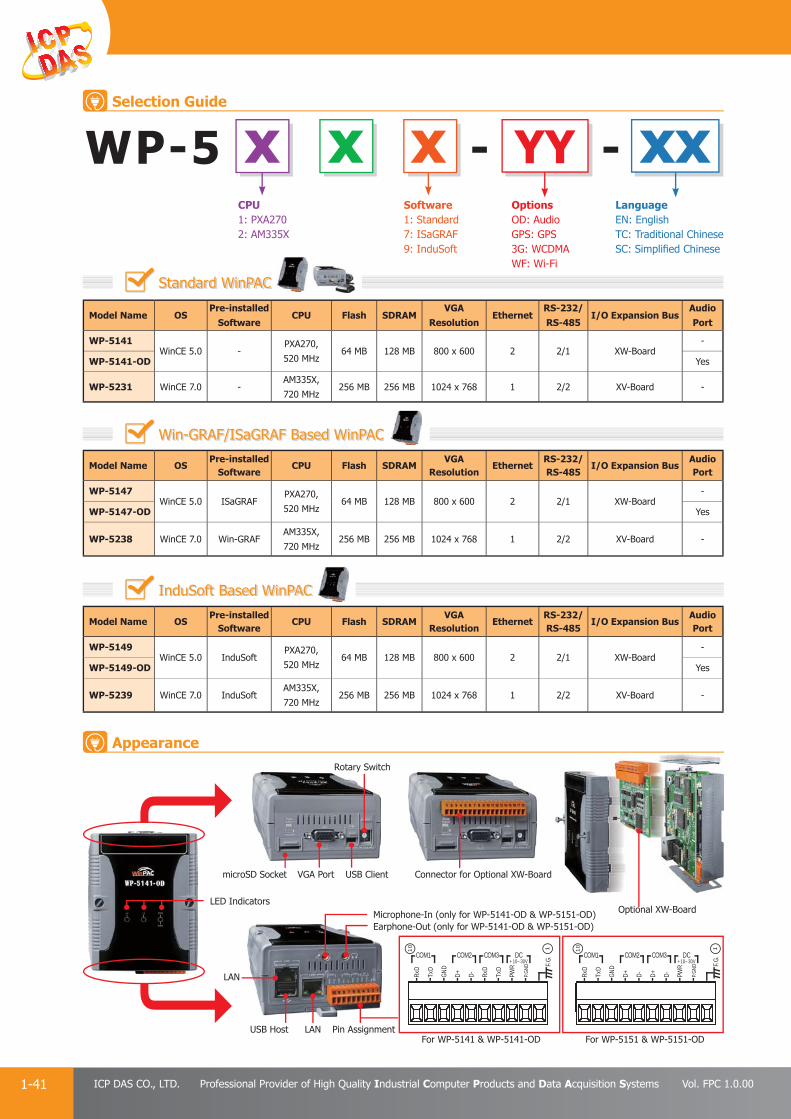
PAC Products
1-41 ICP DAS CO., LTD. Professional Provider of High Quality Industrial Computer Products and Data Acquisition Systems Vol. FPC 1.0.00
WP-5 x x x xxYYCPU1: PXA2702: AM335X
Software1: Standard7: ISaGRAF9: InduSoft
LanguageEN: EnglishTC: Traditional ChineseSC: Simplifi ed Chinese
OptionsOD: AudioGPS: GPS3G: WCDMAWF: Wi-Fi
Standard WinPAC
--
Model Name OSPre-installed
SoftwareCPU Flash SDRAM
VGAResolution
EthernetRS-232/RS-485
I/O Expansion BusAudio Port
WP-5149WinCE 5.0 InduSoft
PXA270,
520 MHz64 MB 128 MB 800 x 600 2 2/1 XW-Board
-
WP-5149-OD Yes
WP-5239 WinCE 7.0 InduSoft AM335X,
720 MHz256 MB 256 MB 1024 x 768 1 2/2 XV-Board -
Model Name OSPre-installed
SoftwareCPU Flash SDRAM
VGAResolution
EthernetRS-232/RS-485
I/O Expansion BusAudio Port
WP-5141WinCE 5.0 -
PXA270,
520 MHz64 MB 128 MB 800 x 600 2 2/1 XW-Board
-
WP-5141-OD Yes
WP-5231 WinCE 7.0 -AM335X,
720 MHz256 MB 256 MB 1024 x 768 1 2/2 XV-Board -
Model Name OSPre-installed
SoftwareCPU Flash SDRAM
VGAResolution
EthernetRS-232/RS-485
I/O Expansion BusAudio Port
WP-5147WinCE 5.0 ISaGRAF
PXA270,
520 MHz64 MB 128 MB 800 x 600 2 2/1 XW-Board
-
WP-5147-OD Yes
WP-5238 WinCE 7.0 Win-GRAFAM335X,
720 MHz256 MB 256 MB 1024 x 768 1 2/2 XV-Board -
Win-GRAF/ISaGRAF Based WinPAC
InduSoft Based WinPAC
VGA Port USB Client
DNG
RWP
DxR
DxT+D -D
DxR
DxT
COM1 COM2 COM3 DC+10~30V
.G.F10
1
DNG.P
DNG
RWP+D -D +D -D
DxR
DxT
COM1 COM2 COM3 DC+10~30V
.G.F10
1
DNG.P
LED Indicators
microSD Socket
LAN
LAN
Pin AssignmentUSB Host
Rotary Switch
Connector for Optional XW-Board
Microphone-In (only for WP-5141-OD & WP-5151-OD)Earphone-Out (only for WP-5141-OD & WP-5151-OD)
Optional XW-Board
For WP-5141 & WP-5141-OD For WP-5151 & WP-5151-OD
Selection Guide
Appearance

PAC Products
1-42E-mail: [email protected] Vol. FPC 1.0.00
Website: http://www.icpdas.com
PA
C P
rodu
cts
Pan
el P
rodu
cts
Rem
ote
I/O
M
odul
e an
d U
nit
DA
Q C
ard
Indu
stri
al
Com
mun
icat
ion
Wir
eles
s So
luti
onM
otio
n
Au
tom
atio
nA
cces
sori
esEn
ergy
M
anag
emen
tSo
luti
on
3.3 LinPAC-5000 Series
Linux kernel
ARM CPU
LP-5000 Series
Wide range of Development Support Tools
Local I/O and Communication Expansion BoardThe LinPAC-5000 series is equipped with an I/O expansion bus to support one optional expansion board, called the XV-Board or XW-Board. It can be used to implement various I/O functions, such as DI, DO, A/D, D/A, Timer/Counter and various communication interfaces, such as RS-232/422/485.
The LinPAC-5000 family is a palm-size PAC and is designed to provide fast, convenient, flexible and simplified solutions for industrial and embedded applications. It is equipped with an ARM CPU running a Linux kernel operating system, multiple communication interfaces (VGA, USB, Ethernet, RS-232/485 and audio ports) and powerful software including development tools.
LinPAC SDK for Windows and Linux Support for GNU C Language Support for GUI: Using GTK + Library Support for DCON, Modbus and SNMP Protocols Support for USB to Serial Converter
Remote I/O ModuleWith the built-in RS-485 and Ethernet ports, the LinPAC-5000 series can connect to remote RS-485/Ethernet I/O units(RU-87Pn/ET-87Pn) or modules (I-7000/M-7000/ET-7000).
1. Ethernet2. RS-232/485
3. USB host4. GPS
5. GSM/GPRS
Multiple Communication InterfacesSeveral different types of communication interface are available that enable I/O modules to be expanded and connected to external devices:
XV-Board or XW-Board
Various Memory Storage OptionsLinPAC-5000 provides various memory storage options, such as EEPROM, Flash or microSD. Customers can choose the memory based on their characteristics.
16 KB EEPROM: to store not frequently changed parameters. microSD/microSDHC: to implement portable data logging applications.
Unique 64-bit Hardware Serial Number to Protect Your ProgramA unique 64-bit serial number is assigned to each hardware device to protect your software against piracy.
Plastic and Metal CasingThe default case is plastic material. Metal casing is also offered to provide extra security.
Highly Reliable Under Harsh EnvironmentsThe LinPAC-5000 operates in a wide range of temperatures and humidity levels.
• Operating Temperature: -25 ~ +75°C
• Storage Temperature: -30 ~ +80°C
• Humidity 10 ~ 90% RH (non-condensing)
Model Name OSPre-installed
SoftwareCPU Flash SDRAM
VGAResolution
EthernetRS-232/RS-485
I/O Expansion Audio Port
LP-5131
Linux kernel
2.6.19-
PXA270,
520 MHz64 MB 128 MB 800 x 600
1
2/1 XW-Board
-
LP-5131-OD Yes
LP-51412
-
LP-5141-OD Yes
LP-5231Linux kernel
3.2.14
AM335X,
720 MHz256 MB 256 MB 1024 x 768 1 2/2 XV-Board -
The controller supports following software development tools:1. SDK for Linux environment2. SDK for Windows environment
Standard LinPAC
Features
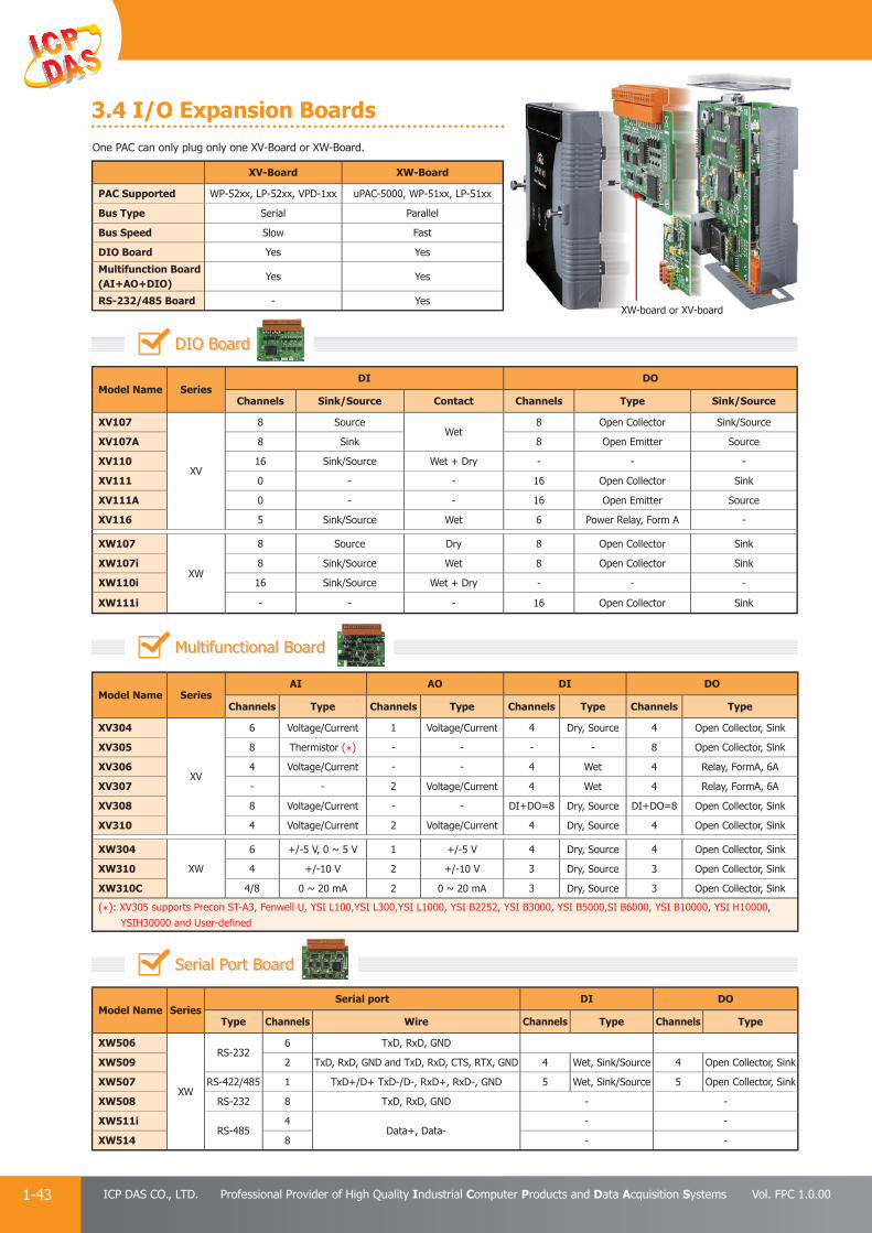
PAC Products
1-43 ICP DAS CO., LTD. Professional Provider of High Quality Industrial Computer Products and Data Acquisition Systems Vol. FPC 1.0.00
One PAC can only plug only one XV-Board or XW-Board.
XV-Board XW-Board
PAC Supported WP-52xx, LP-52xx, VPD-1xx uPAC-5000, WP-51xx, LP-51xx
Bus Type Serial Parallel
Bus Speed Slow Fast
DIO Board Yes Yes
Multifunction Board(AI+AO+DIO)
Yes Yes
RS-232/485 Board - Yes
3.4 I/O Expansion Boards
Model Name SeriesDI DO
Channels Sink/Source Contact Channels Type Sink/Source
XV107
XV
8 SourceWet
8 Open Collector Sink/Source
XV107A 8 Sink 8 Open Emitter Source
XV110 16 Sink/Source Wet + Dry - - -
XV111 0 - - 16 Open Collector Sink
XV111A 0 - - 16 Open Emitter Source
XV116 5 Sink/Source Wet 6 Power Relay, Form A -
XW107
XW
8 Source Dry 8 Open Collector Sink
XW107i 8 Sink/Source Wet 8 Open Collector Sink
XW110i 16 Sink/Source Wet + Dry - - -
XW111i - - - 16 Open Collector Sink
Model Name SeriesSerial port DI DO
Type Channels Wire Channels Type Channels Type
XW506
XW
RS-2326 TxD, RxD, GND
XW509 2 TxD, RxD, GND and TxD, RxD, CTS, RTX, GND 4 Wet, Sink/Source 4 Open Collector, Sink
XW507 RS-422/485 1 TxD+/D+ TxD-/D-, RxD+, RxD-, GND 5 Wet, Sink/Source 5 Open Collector, Sink
XW508 RS-232 8 TxD, RxD, GND - -
XW511iRS-485
4Data+, Data-
- -
XW514 8 - -
Model Name SeriesAI AO DI DO
Channels Type Channels Type Channels Type Channels Type
XV304
XV
6 Voltage/Current 1 Voltage/Current 4 Dry, Source 4 Open Collector, Sink
XV305 8 Thermistor (*) - - - - 8 Open Collector, Sink
XV306 4 Voltage/Current - - 4 Wet 4 Relay, FormA, 6A
XV307 - - 2 Voltage/Current 4 Wet 4 Relay, FormA, 6A
XV308 8 Voltage/Current - - DI+DO=8 Dry, Source DI+DO=8 Open Collector, Sink
XV310 4 Voltage/Current 2 Voltage/Current 4 Dry, Source 4 Open Collector, Sink
XW304
XW
6 +/-5 V, 0 ~ 5 V 1 +/-5 V 4 Dry, Source 4 Open Collector, Sink
XW310 4 +/-10 V 2 +/-10 V 3 Dry, Source 3 Open Collector, Sink
XW310C 4/8 0 ~ 20 mA 2 0 ~ 20 mA 3 Dry, Source 3 Open Collector, Sink
(*): XV305 supports Precon ST-A3, Fenwell U, YSI L100,YSI L300,YSI L1000, YSI B2252, YSI B3000, YSI B5000,SI B6000, YSI B10000, YSI H10000, YSIH30000 and User-defi ned
DIO Board
Serial Port Board
Multifunctional Board
XW-board or XV-board

Introduction P 2-1
iPPC (Industrial Panel PC) P 2-21
SmartView P 2-114
TouchPAD, ViewPAD P 2-145
Touch Monitor P 2-216
ViewPAC P 2-42
IWS (InduSoft) P 2-83
Panel ProductsPanel ProductsPanel Products
Touch Monitor P 2 216
2
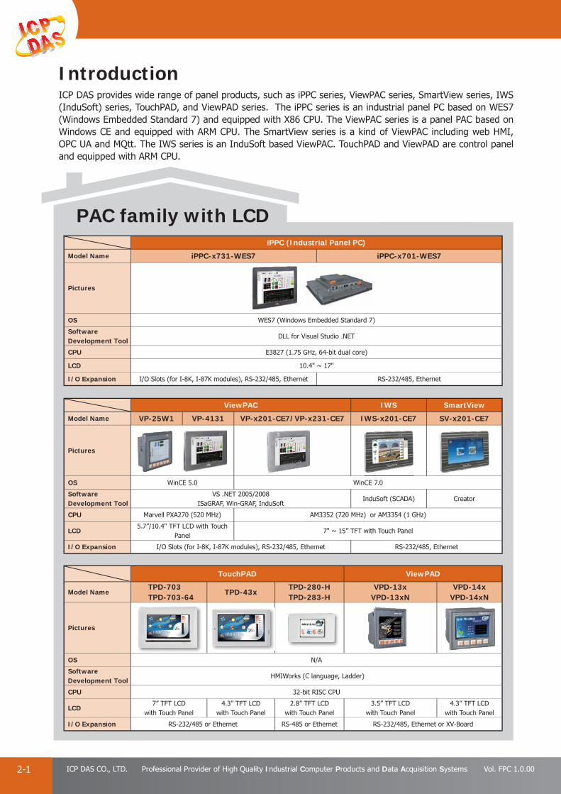
PAC Products
2-1 ICP DAS CO., LTD. Professional Provider of High Quality Industrial Computer Products and Data Acquisition Systems Vol. FPC 1.0.00
PAC family with LCD
IntroductionICP DAS provides wide range of panel products, such as iPPC series, ViewPAC series, SmartView series, IWS (InduSoft) series, TouchPAD, and ViewPAD series. The iPPC series is an industrial panel PC based on WES7 (Windows Embedded Standard 7) and equipped with X86 CPU. The ViewPAC series is a panel PAC based on Windows CE and equipped with ARM CPU. The SmartView series is a kind of ViewPAC including web HMI, OPC UA and MQtt. The IWS series is an InduSoft based ViewPAC. TouchPAD and ViewPAD are control panel and equipped with ARM CPU.
ViewPAC IWS SmartView
Model Name VP-25W1 VP-4131 VP-x201-CE7/VP-x231-CE7 IWS-x201-CE7 SV-x201-CE7
Pictures
OS WinCE 5.0 WinCE 7.0
Software Development Tool
VS .NET 2005/2008ISaGRAF, Win-GRAF, InduSoft
InduSoft (SCADA) Creator
CPU Marvell PXA270 (520 MHz) AM3352 (720 MHz) or AM3354 (1 GHz)
LCD5.7”/10.4" TFT LCD with Touch
Panel7" ~ 15” TFT with Touch Panel
I/O Expansion I/O Slots (for I-8K, I-87K modules), RS-232/485, Ethernet RS-232/485, Ethernet
iPPC (Industrial Panel PC)
Model Name iPPC-x731-WES7 iPPC-x701-WES7
Pictures
OS WES7 (Windows Embedded Standard 7)
Software Development Tool
DLL for Visual Studio .NET
CPU E3827 (1.75 GHz, 64-bit dual core)
LCD 10.4" ~ 17"
I/O Expansion I/O Slots (for I-8K, I-87K modules), RS-232/485, Ethernet RS-232/485, Ethernet
TouchPAD ViewPAD
Model Name TPD-703TPD-703-64
TPD-43xTPD-280-HTPD-283-H
VPD-13xVPD-13xN
VPD-14xVPD-14xN
Pictures
OS N/A
Software Development Tool
HMIWorks (C language, Ladder)
CPU 32-bit RISC CPU
LCD7” TFT LCD
with Touch Panel4.3” TFT LCD
with Touch Panel2.8” TFT LCD
with Touch Panel3.5” TFT LCD
with Touch Panel4.3” TFT LCD
with Touch Panel
I/O Expansion RS-232/485 or Ethernet RS-485 or Ethernet RS-232/485, Ethernet or XV-Board
CE 7 0
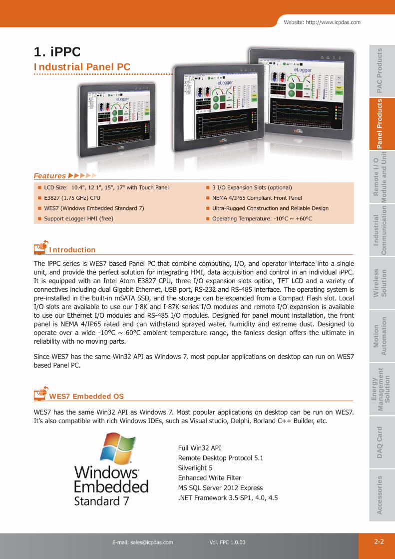
PAC Products
2-2E-mail: [email protected] Vol. FPC 1.0.00
Website: http://www.icpdas.com
PA
C P
rodu
cts
Pan
el P
rodu
cts
Rem
ote
I/O
M
odul
e an
d U
nit
DA
Q C
ard
Indu
stri
al
Com
mun
icat
ion
Wir
eles
s So
luti
onM
otio
n
Au
tom
atio
nA
cces
sori
esEn
ergy
M
anag
emen
tSo
luti
on
1. iPPC
Full Win32 APIRemote Desktop Protocol 5.1Silverlight 5Enhanced Write FilterMS SQL Server 2012 Express.NET Framework 3.5 SP1, 4.0, 4.5
The iPPC series is WES7 based Panel PC that combine computing, I/O, and operator interface into a single unit, and provide the perfect solution for integrating HMI, data acquisition and control in an individual iPPC. It is equipped with an Intel Atom E3827 CPU, three I/O expansion slots option, TFT LCD and a variety of connectives including dual Gigabit Ethernet, USB port, RS-232 and RS-485 interface. The operating system is pre-installed in the built-in mSATA SSD, and the storage can be expanded from a Compact Flash slot. Local I/O slots are available to use our I-8K and I-87K series I/O modules and remote I/O expansion is available to use our Ethernet I/O modules and RS-485 I/O modules. Designed for panel mount installation, the front panel is NEMA 4/IP65 rated and can withstand sprayed water, humidity and extreme dust. Designed to operate over a wide -10°C ~ 60°C ambient temperature range, the fanless design offers the ultimate in reliability with no moving parts.
Since WES7 has the same Win32 API as Windows 7, most popular applications on desktop can run on WES7 based Panel PC.
WES7 has the same Win32 API as Windows 7. Most popular applications on desktop can be run on WES7. It’s also compatible with rich Windows IDEs, such as Visual studio, Delphi, Borland C++ Builder, etc.
Introduction
WES7 Embedded OS
LCD Size: 10.4", 12.1", 15", 17" with Touch Panel 3 I/O Expansion Slots (optional)
E3827 (1.75 GHz) CPU NEMA 4/IP65 Compliant Front Panel
WES7 (Windows Embedded Standard 7) Ultra-Rugged Construction and Reliable Design
Support eLogger HMI (free) Operating Temperature: -10°C ~ +60°C
Features
Industrial Panel PCC
al Panel PC

PAC Products
2-3 ICP DAS CO., LTD. Professional Provider of High Quality Industrial Computer Products and Data Acquisition Systems Vol. FPC 1.0.00
● Selection Guide
Model Name LCD CPU Flash RAM Memory Expansion Ethernet I/O slot COM port
iPPC-4701-WES7 10.4” (800 x 600)
E3827 (1.75 GHz) 16 GB 2 GB CF
1
-
2
iPPC-5701-WES7 12.1” (800 x 600) 1 3
iPPC-6701-WES7 15” (1024 x 768) 2 3
iPPC-7701-WES7 17” (1280 x 1024) 2 3
Model Name LCD CPU Flash RAM Memory Expansion Ethernet I/O slot COM port
iPPC-5731-WES7 12.1” (800 x 600)
E3827 (1.75 GHz) 16 GB 2 GB CF 2 3 3iPPC-6731-WES7 15” (1024 x 768)
iPPC-7731-WES7 17” (1280 x 1024)
Panel PC with x86 CPU and WES7 OS
iPPC - -1xx x xxI/O slot 0: w/o slot3: 3 slot
CPU Type7: E3827
OSWES7
Software1: Standard(VC, VB, C#)
Display4: 10.4” LCD 6: 15” LCD5: 12.1” LCD 7: 17” LCD
12.1” TFT LCD800 x 600 (4 : 3)
Indicators(PWR, RUN, L1, L2)
COM3(RS-485)
COM4(RS-232/RS-485)
COM2 (RS-232)
CF Slot
Rotary Switch
USB 2.0 x 2Earphone-out
Redundant power
LAN1 and LAN2
15” TFT LCD1024 x 768 (4 : 3)
Indicators(PWR, RUN, L1, L2)
COM3(RS-485)
COM4(RS-232/RS-485)
COM2 (RS-232)
CF Slot
Rotary Switch
USB 2.0 x 4
Mic-in and earphone-out
Redundant power
LAN1 and LAN2
iPPC-6731-WES7iPPC-5731-WES7
Appearance
I/O Expansion

PAC Products
2-4E-mail: [email protected] Vol. FPC 1.0.00
Website: http://www.icpdas.com
PA
C P
rodu
cts
Pan
el P
rodu
cts
Rem
ote
I/O
M
odul
e an
d U
nit
DA
Q C
ard
Indu
stri
al
Com
mun
icat
ion
Wir
eles
s So
luti
onM
otio
n
Au
tom
atio
nA
cces
sori
esEn
ergy
M
anag
emen
tSo
luti
on
≒≒ +
● Introduction
ViewPAC is an ARM-based PAC that combines a display, an I/O module and control in a single unit, and provide the perfect solution for integrating HMI, data acquisition and control in an individual PAC. Normally, HMIs and controllers operate separately.
ViewPAC IPC + Display PLCWinPAC/iPAC + Display
2. ViewPAC

PAC Products
2-5 ICP DAS CO., LTD. Professional Provider of High Quality Industrial Computer Products and Data Acquisition Systems Vol. FPC 1.0.00
Ethernet
RS-232/485
USB host
CAN bus
FRnet
GSM/GPRS/GPS
ZigBee
2. LCD Display5.7”, 7”, 8.4”, 10.4", 12.1”, 15” TFT LCD with touch panel
3. I/O SlotsThe I/O slots support parallel bus (high profi le I-8K series) and serial bus (high profi le I-87K series) type I/O modules, and there are more than 60 kinds of module available for AI, AO, DI, DO, counter input, frequency input, PWM output, motion control, memory, and communication, etc.
4. Multiple Communication InterfacesSeveral different types of communication interface are available that enable I/O modules to be expanded and connected to external devices:
1. Ethernet2. RS-232/4853. USB host4. CAN bus
5. FRnet 6. GSM/GPRS/GPS7. ZigBee
● Features
Full Win32 API Remote Desktop Protocol 5.1 Silverlight 5 Enhanced Write Filter
MS SQL Server 2012 Express .NET Framework 3.5 SP1, .Net Framework 4.0, and .Net Framework 4.5
1. A variety of CPU and OS options for selection
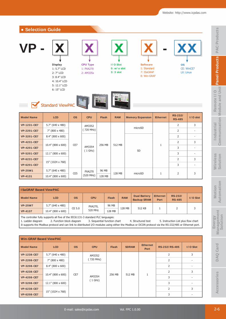
PAC Products
2-6E-mail: [email protected] Vol. FPC 1.0.00
Website: http://www.icpdas.com
PA
C P
rodu
cts
Pan
el P
rodu
cts
Rem
ote
I/O
M
odul
e an
d U
nit
DA
Q C
ard
Indu
stri
al
Com
mun
icat
ion
Wir
eles
s So
luti
onM
otio
n
Au
tom
atio
nA
cces
sori
esEn
ergy
M
anag
emen
tSo
luti
on
● Selection Guide
Standard ViewPAC
ISaGRAF Based ViewPAC
Model Name LCD OS CPU Flash RAMDual Battery
Backup SRAMEthernet
PortRS-232/RS-485
I/O Slot
VP-25W7 5.7” (640 x 480)CE 5.0
PXA270, 520 MHz
96 MB128 MB 512 KB 1 2 3
VP-4137 10.4” (800 x 600) 128 MB
The controller fully supports all fi ve of the IEC61131-3 standard PLC languages:1. Ladder diagram 2. Function block diagram 3. Sequential function chart 4. Structured text 5. Instruction List plus fl ow chart It supports the Modbus protocol and can link to distributed I/O modules using either the Modbus or DCON protocol via the RS-232/485 or Ethernet port.
Win-GRAF Based ViewPAC
Model Name LCD OS CPU Flash SDRAMEthernet
PortRS-232/RS-485 I/O Slot
VP-1238-CE7 5.7” (640 x 480)
CE7
AM3352( 720 MHz)
256 MB 512 MB 1
2 3
VP-2208-CE7 7” (800 x 480) 2 -
VP-3208-CE7 8.4” (800 x 600)
AM3354( 1 GHz)
2 -
VP-4238-CE710.4” (800 x 600)
2 3
VP-4208-CE7 3 -
VP-5208-CE7 12.1” (800 x 600) 3 -
VP-6238-CE715” (1024 x 768)
2 3
VP-6208-CE7 3 -
VP - -x xx x xxSoftware1: Standard7: ISaGRAF8: Win-GRAF
I/O Slot 0: w/o slot3: 3 slot
OSCE: WinCE7LX: Linux
CPU Type1: PXA270
2: AM335x
Display1: 5.7” LCD
2: 7” LCD
3: 8.4” LCD
4: 10.4” LCD
5: 12.1” LCD
6: 15” LCD
Model Name LCD OS CPU Flash RAM Memory Expansion EthernetRS-232/RS-485
I/O slot
VP-1231-CE7 5.7” (640 x 480)
CE7
AM3352( 720 MHz)
256 MB 512 MB
microSD
1
2 3
VP-2201-CE7 7” (800 x 480) 2 -
VP-3201-CE7 8.4” (800 x 600)
AM3354( 1 GHz) SD
2 -
VP-4231-CE710.4” (800 x 600)
2 3
VP-4201-CE7 3 -
VP-5201-CE7 12.1” (800 x 600) 3 -
VP-6231-CE715” (1024 x 768)
2 3
VP-6201-CE7 3 -
VP-25W1 5.7” (640 x 480)CE5
PXA270(520 MHz)
96 MB128 MB microSD 1 2 3
VP-4131 10.4” (800 x 600) 128 MB
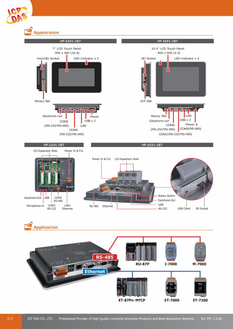
PAC Products
2-7 ICP DAS CO., LTD. Professional Provider of High Quality Industrial Computer Products and Data Acquisition Systems Vol. FPC 1.0.00
VP-1231-CE7
VP-2201-CE7 VP-4201-CE7
I/O Expansion Slots Power In & F.G.
COM3RS-232
LAN1Ethernet
COM2RS-485
USBEarphone-Out
Microphone-In
I/O Expansion Slots
SD Socket
Power In & F.G.
USB ClientUSB
Earphone-Out
EthernetRS-485RS-232
Rotary Switch
VP-4231-CE7
LED Indicator x 2
7” LCD Touch Panel800 x 480 (16:9)
Earphone-out
COM2(RS-232/RS-485)
COM1(RS-232/RS-485)
PowerUSB x 2
LAN
Rotary SW.
microSD Socket LED Indicator x 2
10.4” LCD Touch Panel800 x 600 (4:3)
SD Socket
Rotary SW.
Earphone-outCOM2
(RS-232/RS-485)
Power &COM3(RS-485)
USB x 2LAN
COM1(RS-232/RS-485)
DIP SW.
Appearance
Application

PAC Products
2-8E-mail: [email protected] Vol. FPC 1.0.00
Website: http://www.icpdas.com
PA
C P
rodu
cts
Pan
el P
rodu
cts
Rem
ote
I/O
M
odul
e an
d U
nit
DA
Q C
ard
Indu
stri
al
Com
mun
icat
ion
Wir
eles
s So
luti
onM
otio
n
Au
tom
atio
nA
cces
sori
esEn
ergy
M
anag
emen
tSo
luti
on
The IWS PAC series is the new generation WinCE 7.0 based InduSoft PAC of ICP DAS. It combines an ARM-based CPU board, TFT LCD touch screen to create a ruggedized, fl at panel computer perfect for a variety of control and HMI applications. It provides a variety of connectives including Gigabit Ethernet, USB port, RS-232 and RS-485. The operating system is pre-installed in the on-board Flash memory. Remote I/O expansion is available using our Ethernet I/O modules, RS-485 I/O modules, Wi-Fi and ZigBee wireless I/O modules. Designed for panel mount installation, the front panel is NEMA 4/IP65 rated and can withstand sprayed water, humidity and extreme dust. Designed to operate over a wide -10°C ~ 60°C ambient temperature range, the fanless design offers the ultimate in reliability with no moving parts.
Alarms
In addition to the many alarm functions you expect from InduSoft Web Studio, v7.1 also sends online alarms or reports using multi-media formats like PDF.Alarms are real-time and historical; log data in binary format or to any database. Use remote notifi cation to have alarms sent right to your inbox, printer, or smartphone! Custom Alarm fi elds allow you to customize up to 10 additional fi elds to the history of alarms.
Recipe / Report
Save time and maintain consistency by automating part parameters or production quantities with flexible recipe management tools. Create clear, concise reports in plain text, RTF, XML, PDF, HTML, and CSV or integrate with Microsoft Offi ce programs such as Excel. Get the data you need, in the format you need it, to make informed decisions, fast. InduSoft has also partnered with Ocean Data Systems to offer further reporting capabilities through Dream Report for InduSoft Web Studio, available as an add-on.
InduSoft Runtime Inside Resistive Touch Panel
Support Modbus, OPC, TCP/IP Client/Server AM335x (1 GHz or 720 MHz) CPU
DCON Driver for ICP DAS I/O modules provided Windows CE 7.0
Makes connectivity for the “internet of things” and mobile devices easily NEMA 4/IP65 Compliant Front Panel
7”/8.4”/10.4”/12.1"/15" LCD Operating Temperature: -10 ~ +60°C
Resolution: 800 x 480 ~ 1024 x 768 VESA Mounting
Features
3. IWS (InduSoft)
Introduction
InduSoft Features
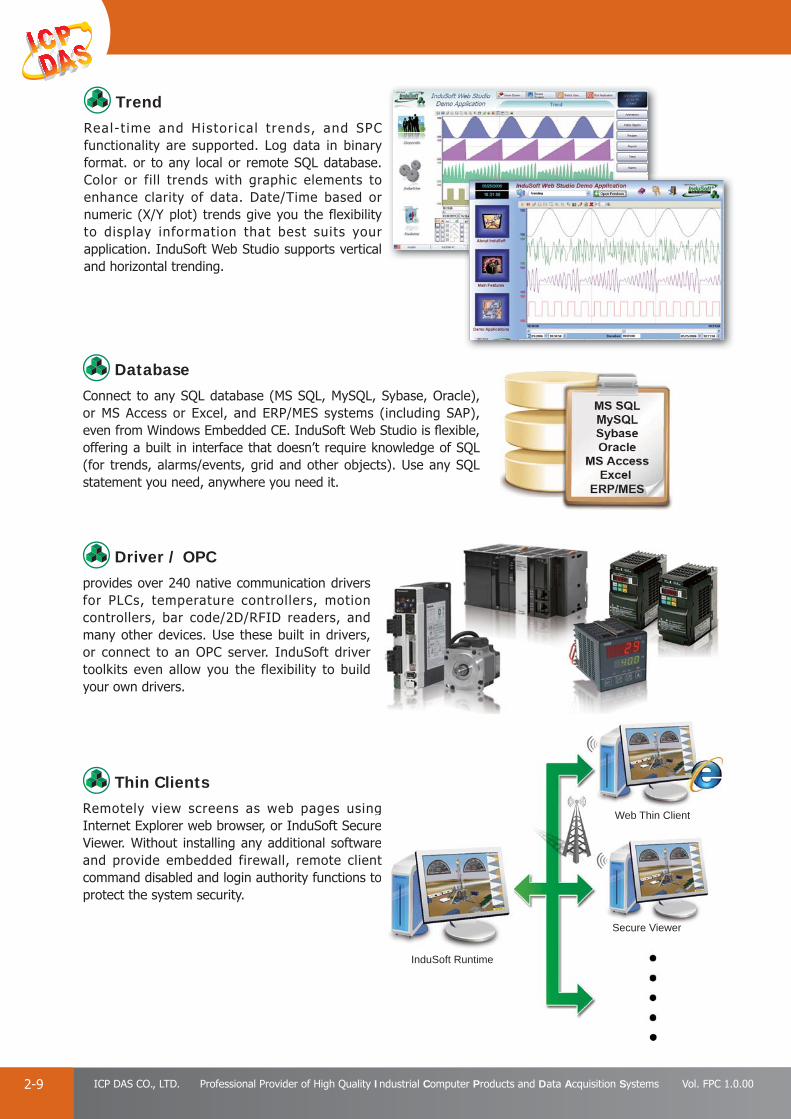
PAC Products
2-9 ICP DAS CO., LTD. Professional Provider of High Quality Industrial Computer Products and Data Acquisition Systems Vol. FPC 1.0.00
Driver / OPCprovides over 240 native communication drivers for PLCs, temperature controllers, motion controllers, bar code/2D/RFID readers, and many other devices. Use these built in drivers, or connect to an OPC server. InduSoft driver toolkits even allow you the flexibility to build your own drivers.
DatabaseConnect to any SQL database (MS SQL, MySQL, Sybase, Oracle), or MS Access or Excel, and ERP/MES systems (including SAP), even from Windows Embedded CE. InduSoft Web Studio is fl exible, offering a built in interface that doesn’t require knowledge of SQL (for trends, alarms/events, grid and other objects). Use any SQL statement you need, anywhere you need it.
Thin ClientsRemotely view screens as web pages using Internet Explorer web browser, or InduSoft Secure Viewer. Without installing any additional software and provide embedded firewall, remote client command disabled and login authority functions to protect the system security.
TrendReal-t ime and Histor ica l t rends, and SPC functionality are supported. Log data in binary format. or to any local or remote SQL database. Color or fill trends with graphic elements to enhance clarity of data. Date/Time based or numeric (X/Y plot) trends give you the flexibility to display information that best suits your application. InduSoft Web Studio supports vertical and horizontal trending.
g e e t o
Web Thin Client
InduSoft Runtime
Secure Viewer

PAC Products
2-10E-mail: [email protected] Vol. FPC 1.0.00
Website: http://www.icpdas.com
PA
C P
rodu
cts
Pan
el P
rodu
cts
Rem
ote
I/O
M
odul
e an
d U
nit
DA
Q C
ard
Indu
stri
al
Com
mun
icat
ion
Wir
eles
s So
luti
onM
otio
n
Au
tom
atio
nA
cces
sori
esEn
ergy
M
anag
emen
tSo
luti
on
● Selection Guide
InduSoft Based ViewPAC
IWS - - CE7x xxI/O Slot 0: w/o slot
CPU Type2: AM335x
Display2: 7” LCD 3: 8.4” LCD 4: 10.4” LCD 5: 12.1 LCD6: 15” LCD
Model Name LCD OS CPU Flash RAM Memory Expansion EthernetRS-232/RS-485
I/O slot
IWS-2201-CE7 7” (800 x 480)
CE7
AM3352( 720 MHz)
256 MB 512 MB
microSD
1
2
-
IWS-3201-CE7 8.4” ( 800 x 600)
AM3354( 1 GHz)
SD
IWS-4201-CE7 10.4” (800 x 600)
3IWS-5201-CE7 12.1” (800 x 600)
IWS-6201-CE7 15” (1024 x 768)
1
IWS-6201-CE7
LAN1(RJ-45)
USB x 2USB x 2
Audio-Out
Power
COM2(RS-232/485)
COM1(RS-232/485)
Rotary SW.
Rotary SW.
IWS-2201-CE7 IWS-4201-CE7
LAN1(RJ-45)
USB x 2
PowerCOM3(RS-485) Rotary SW.
7” LCD Touch Panel800 x 480 (16:9)
LED Indicator LED Indicator
10.4” LCD Touch Panel800 x 600 (4:3)
15” LCD Touch Panel1024 x 768 (4:3)
COM2(RS-232/485) COM1(RS-232/485)
Audio-Out
COM3(RS-485)
LAN1(RJ-45)Audio-Out
Power
COM2(RS-232/485) COM1(RS-232/485)
LED Indicator
Appearance

PAC Products
2-11 ICP DAS CO., LTD. Professional Provider of High Quality Industrial Computer Products and Data Acquisition Systems Vol. FPC 1.0.00
The SmartView series combines an ARM-based CPU board, TFT LCD touch screen and software including Web HMI, OPC UA, and MQTT to create a ruggedized, fl at panel computer perfect for a variety of control and HMI applications. It provides a variety of connectives including Gigabit Ethernet, USB port, RS-232 and RS-485. The operating system is pre-installed in the on-board Flash memory. Remote I/O expansion is available using our Ethernet I/O modules, RS-485 I/O modules, Wi-Fi and ZigBee wireless I/O modules. Designed for panel mount installation, the front panel is NEMA 4/IP65 rated and can withstand sprayed water, humidity and extreme dust. Designed to operate over a wide -10°C ~ 60°C ambient temperature range, the fanless design offers the ultimate in reliability with no moving parts.
Creator is a cross-platform Web HMI Integrated Development Environment (IDE) for designing Windows-based and Linux-based SmartView Panel. It provides an easy-to-use Graphic User Interface (GUI) and diverse objects to integrate into HMI applications without coding for developing customized SmartView. With Creator, an application can deploy web HMI screens on the SmartView, allowing the operator to control and monitor the process in a web browser crossing multi-platform from PC, smart phone and smart pad in everywhere. On design phase, user only needs to concentrate on designing local HMI, dynamic web page can be generated by Creator automatically via creator compiler. In addition, the Creator also supports the new generation industrial communication standard “OPC UA”, “Internet of Things” transmission “MQTT”, 18 common protocols for communication, and I/O status simulation in designing process. Combined with these features, Creator can dramatically save development time and make the SmartView development more effi ciently.
Key features of the Creator Software:
Support 18 Common Protocols Easy To Create HMI Project Without Coding Diversifi cation HMI Objects and Functions
- Alarm, Schedule, Recipe, Data Log, Macro… Designed Once, Display Everywhere! (Local HMI & Web HMI)
- Web HMI Support Smart Phone & Pad Update Project Through Ethernet/USB Support Remote Control Support OPC UA Support MQTT On-line/Off-line Simulation Support Multi-language (Traditional Chinese / Simplifi ed Chinese / English)
Cross-platform Web HMI IDE: Creator Resistive Touch Panel
Industrial Automation Standard: OPC UA AM335x (1 GHz or 720 MHz) CPU
Active M2M Transmission Mechanism: MQTT Windows CE 7.0
Makes connectivity for the “internet of things” and mobile devices easily NEMA 4/IP65 Compliant Front Panel
Support Remote Control Operating Temperature: -10 ~ +60°C
7”/8.4”/10.4”/12.1"/15" LCD VESA Mounting
Resolution: 800 x 480 ~ 1024 x 768
Features
4. SmartView
Introduction
Creator: Powerful and Cross-platform Web HMI IDE
w

PAC Products
2-12E-mail: [email protected] Vol. FPC 1.0.00
Website: http://www.icpdas.com
PA
C P
rodu
cts
Pan
el P
rodu
cts
Rem
ote
I/O
M
odul
e an
d U
nit
DA
Q C
ard
Indu
stri
al
Com
mun
icat
ion
Wir
eles
s So
luti
onM
otio
n
Au
tom
atio
nA
cces
sori
esEn
ergy
M
anag
emen
tSo
luti
on
MQTT is a method of Machine to Machine (M2M) communication by writing and retrieving application-specifi c data (messages) to and from queues, without having a private, dedicated connection to link them. It simplifi es and accelerates the integration of diverse applications data between SmartView under assured, secure and reliable exchange of information circumstance. Using MQTT in SmartView not only dramatically simplifi es the creation and maintenance of Industrial application but also makes connectivity for the “internet of things” and mobile devices easily.
MQTT Features: Rapid, seamless connectivity of information with a single, robust and trusted messaging backbone for dynamic heterogeneous environments.
Secure, reliable message delivery that preserves message integrity and minimizes risk of information loss.
High-performance and scalable message transfer to meet the demands of today’s enterprise and beyond.
Simplifi ed management and control for better control and usability.
Lower cost of ownership by reducing cost of integration and accelerating time to deployment.
OPC UA is the interoperability standard for security, reliable multivendor, multiplatform data exchange for Industrial Automation. It extends the classical OPC communication protocol, enabling data acquisition and information modeling and communication between the plant fl oor and the enterprise reliably and securely.
Key Features of OPC UA are: Platform Independent Data Communication OPC UA is designed to
be independent of the platform. Using SOAP/XML over HTTP, OPC UA can be deployed on Linux, Windows XPEmbedded, Windows 7, and Classical Windows platforms.
Unifi ed AccessOPC UA integrates existing OPC specifi cations DA, A&E, HDA, Commands, Complex data, and Object Types in one specifi cation. This reduces system integration costs by providing a common architecture for accessing information.
Standardized Communication via Firewalls and Internet OPC UA uses
message based security which means messages can be relayed through HTTP, UA TCP port or any other single port available.
Reliability & RedundancyOPC UA implements a configurable timeouts, error detection, and communication failure recovery. OPC UA allows redundancy between applications from different vendors to be deployed.
SecurityOPC UA is Secure-by-default, encryption enabled, and uses advanced certificate handling which includes Authentication, Authorization, Confi dentiality, and Integrity.
OPC UA: New Generation Industrial Communication Standard
MQTT: Active M2M Transmission Mechanism
easily.
rnts.
d
nds
for
g

PAC Products
2-13 ICP DAS CO., LTD. Professional Provider of High Quality Industrial Computer Products and Data Acquisition Systems Vol. FPC 1.0.00
● Selection Guide
SmartView Panel PC
SV - -xxI/O Slot 0: w/o slot
CPU Type2: AM335x
Display2: 7” LCD
3: 8.4” LCD
4: 10.4” LCD
5: 12.1” LCD
6: 15” LCD
Model Name LCD OS CPU Flash RAM Memory Expansion Ethernet I/O slot COM port
SV-2201-CE7 7” (800 x 480)
CE7
AM3352( 720 MHz)
256 MB 512 MB
microSD
1 -
2
SV-3201-CE7 8.4” (800 x 600)
AM3354( 1 GHz)
SD
SV-4201-CE7 10.4” (800 x 600)
3SV-5201-CE7 12.1” (800 x 600)
SV-6201-CE7 15” (1024 x 768)
10 xxOSCE: WinCE7LX: LinuxAndroid
SV-6201-CE7SV-2201-CE7 SV-4201-CE7
LAN1(RJ-45)
USB x 2 USB x 2
Audio-Out
Power
COM2(RS-232/485)
COM1(RS-232/485)
Rotary SW.Rotary SW. USB
x 2Power
COM3(RS-485) Rotary SW.
7” LCD Touch Panel800 x 480 (16:9)
LED Indicator LED Indicator LED Indicator
10.4” LCD Touch Panel800 x 600 (4:3)
15” LCD Touch Panel1024 x 768 (4:3)
COM2(RS-232/485) COM1(RS-232/485)
Audio-Out
COM3(RS-485)
LAN1(RJ-45) LAN1(RJ-45)Audio-Out
Power
COM2(RS-232/485) COM1(RS-232/485)
Appearance

PAC Products
2-14E-mail: [email protected] Vol. FPC 1.0.00
Website: http://www.icpdas.com
PA
C P
rodu
cts
Pan
el P
rodu
cts
Rem
ote
I/O
M
odul
e an
d U
nit
DA
Q C
ard
Indu
stri
al
Com
mun
icat
ion
Wir
eles
s So
luti
onM
otio
n
Au
tom
atio
nA
cces
sori
esEn
ergy
M
anag
emen
tSo
luti
on
5. TouchPAD, ViewPADThe Best Choice for Building/Factory/Machine/Home Automation
Excellent C/P ratio (cost/performance) Free development tool: HMIWorks
High-color high-resolution touch screen Support the C language and Ladder Designer
Power over Ethernet (PoE) Support user-defi ned third party protocol(C language)
RS-485 (including SelfTuner)/RS-232 (3 pins) Modbus protocol enables remote control of I/O modules and integration with SCADA softwareRTC (Real Time Clock)
Buzzer ESD Protection: 4 kV
Rubber Keypad (Option for VPD Series) Waterproof Front Panel ( VPD: IP65)
Graphical user interface designer Operating temperature: -20 ~50°C (2.8" TPD: -20 ~ 70°C)
≒ +
● Introduction
ICP DAS provides two types of touch HMI devices, the TPD series and the VPD series. The TPD series is designed for home/building automation applications and the VPD series is designed for factory/machine automation applications. Both have many common features, such as a high-color high-resolution touch screen, RTC, and a variety of communication interfaces, including RS-232/RS-485 and Ethernet. However, each still has its own specifi c features for its respective target applications. For the TPD series, users can use an external wall box to help smoothly blend the TPD series device into decoration. For the VPD series, the rubber keypad, IP-65 waterproof front panel and DIN-Rail/panel mounting are designed for harsh environment, and are especially suitable for factories.
HMIWorks is a free development tool that can be used to design ladder diagrams for softPLC logic for TouchPAD. A single TouchPAD becomes a touch HMI device which runs ladder logics.
TouchPAD Ladder DiagramLadder DiagramHMIHMI
TPD Series VPD Series
Features

PAC Products
2-15 ICP DAS CO., LTD. Professional Provider of High Quality Industrial Computer Products and Data Acquisition Systems Vol. FPC 1.0.00
5. C and Ladder Diagram Programming
1. Support Many Widgets - Shorten Development TimeSupport Many Widgets - Shorten Development Time There are many widgets included in the HMIWorks development tool, including Rectangle, Ellipse, Text, Picture, Line, TextPushButton, Slider, BitButton, HotSpot, CheckBox, Label, Timer, PaintBox, ObjectList, providing the most commonly-used functions, such as drawings, event handlers, and timing control, which effectively shortens development time.
2. Built-in the Extensible Graphics LibraryHMIWorks supports simple graphics functions and provides users with a variety of built-in graphics for common situations. Users can also add their own graphics to the library by the common painting or photo editing software.
4. Intuitive DesignHMIWorks provides a intuitive graphical design interface that allows users to focus on what they want to do. By getting rid of the programming details and being more intuitive, everyone can easily fi nish their projects.
3. 65536 Colors - Bright and ClearPresently, LCD touch screens are available at 2.8”, 3.5”, 4.3” and the TouchPAD series includes different resolutions from 240 x 320 x 16 to 480 x 272 x 16. ICP DAS will expand this range in the future.
6. Drag-and-drop Design - fully integrate with I/O (support third party modules)ICP DAS now supports many I/O devices, such as ET-7000/PET-7000 series Modbus TCP modules, M-7000 series Modbus RTU modules, I-7000 series DCON modules and user-defi ned third party Modbus TCP devices. Users can expect that additional I/O devices will be supported by HMIWorks for the TouchPAD series in the future.
● HMIWorks - Free Development Software
HMIWorks The development software for the TouchPAD series
j
HMIWorks is a free development software for TouchPAD series products of ICP DAS. It features of many widgets, built-in extensible graphics library, intuitive design, C programming, Ladder Diagram supporting, fully I/O integration... etc. Using with TouchPAD series devices, HMIWorks can help users to short the development time and design the sophisticated, cost effective solutions for the complex systems.

PAC Products
2-16E-mail: [email protected] Vol. FPC 1.0.00
Website: http://www.icpdas.com
PA
C P
rodu
cts
Pan
el P
rodu
cts
Rem
ote
I/O
M
odul
e an
d U
nit
DA
Q C
ard
Indu
stri
al
Com
mun
icat
ion
Wir
eles
s So
luti
onM
otio
n
Au
tom
atio
nA
cces
sori
esEn
ergy
M
anag
emen
tSo
luti
on
T P D - -Communication InterfaceCommunication Interface0: 1 x RS-4850: 1 x RS-4852: 2 x COM ports2: 2 x COM ports3: Ethernet and COM port3: Ethernet and COM port(U): with extra Flash(U): with extra Flash
EU: For European EU: For European 86 x 86 mm Outlet Box86 x 86 mm Outlet Box
xx x(x) xxLCDLCD28: 2.8”28: 2.8”43: 4.3”43: 4.3”70: 7.0”70: 7.0”
2.8” (Resolution: 240 x 320)
2.8” (Resolution: 240 x 320)
4.3” (Resolution: 480 x 272)
7” (Resolution: 800 x 480)
Model Name Extra FlashImage Storage
CapacityEthernet COM port RTC Outlet Box
External Wall Box
Power Input
TPD-280-
1 - 1x RS-485-
OB120 EWB-T28
+10 ~ 30 VDC
TPD-283 1 Yes - PoE
TPD-280U 8 MB 54 - 1x RS-485Yes
+10 ~ 30 VDC
TPD-283U 8 MB 54 Yes 1x RS-485 +10 ~ 30 VDC or PoE
Model Name Extra FlashImage Storage
CapacityEthernet COM port RTC Outlet Box
External Wall Box
Power Input
TPD-280-M1/M2/M3-
4 - 1x RS-485 -
OB120 EWB-T28
+12 ~ 48 VDC
TPD-283-M1/M2/M3 4 Yes - - PoE
TPD-283U-M1/M2/M3 16 MB 108 Yes 1x RS-485 Yes +12 ~ 48 VDC or PoE
Model Name Extra FlashImage Storage
CapacityEthernet COM port RTC Outlet Box
External Wall Box
Power Input
TPD-430
8 MB 32
- 1x RS-485
Yes
OB120 EWB-T43+10 ~ 30 VDC
TPD-433 Yes 1x RS-485 +10 ~ 30 VDC or PoE
TPD-432F - 2x RS-485OB140F OB140FP
EWB-T43F+10 ~ 30 VDC
TPD-433F Yes1x RS-2321x RS-485
+10 ~ 30 VDC or PoE
TPD-430-EU - 1x RS-485- -
+10 ~ 30 VDC
TPD-433-EU Yes 1x RS-485 +10 ~ 30 VDC or PoE
Model Name Extra FlashImage Storage
CapacityEthernet COM port RTC Outlet Box
External Wall Box
Power Input
TPD-703 16 MB 18Yes
1x RS-2321x RS-485
Yes OB170 EWB-T70 +12~48 VDC or PoETPD-703-64 64 MB 84
Note1: Image Storage Capacity depends on the content of program and the size of images. The number is counted by how many images in full screen size can be stored on the device.
Note2: PoE (Power over Ethernet) specifi cation: IEEE 802.3af, Class 1, 48 V
M1 M2 M3
Selection Guide
PAC Products
2-17 ICP DAS CO., LTD. Professional Provider of High Quality Industrial Computer Products and Data Acquisition Systems Vol. FPC 1.0.00
EWB-T28 (External Wall Box)
EWB-T70 (External Wall Box)
OB120 (Outlet Box)
OB170 (Outlet Box)
OB120 (Outlet Box)
OB140F (Outlet Box)
Mounted to European-standard 86 mm x 86 mm
outlet box.
EWB-T43 (External Wall Box)
EWB-T43F (External Wall Box)
OB-140FP (Outlet Box)
For 2.8” (TPD-280/TPD-280U/TPD-283/TPD-283U)
For 7” (TPD-703, TPD-703-64)
For 4.3” (TPD-430, TPD-433)
For 4.3” (TPD-432F, TPD-433F)
For 4.3” (TPD-430-EU, TPD-433-EU)
External Wall Box and Outlet Box

PAC Products
2-18E-mail: [email protected] Vol. FPC 1.0.00
Website: http://www.icpdas.com
PA
C P
rodu
cts
Pan
el P
rodu
cts
Rem
ote
I/O
M
odul
e an
d U
nit
DA
Q C
ard
Indu
stri
al
Com
mun
icat
ion
Wir
eles
s So
luti
onM
otio
n
Au
tom
atio
nA
cces
sori
esEn
ergy
M
anag
emen
tSo
luti
on
TPD-280(U)/TPD-283(U) Front View
TPD-430(-EU)/TPD-433(-EU)Front View
TPD-280 Rear View TPD-280U Rear View TPD-283 Rear View TPD-283U Rear View
Ethernet
Ethernet Ethernet
Ethernet 2.8” TFT LCD with Touch Panel
SpeakerLED
4.3” TFT LCD with Touch Panel
USB
TPD-430-EU Rear View TPD-433 Rear View TPD-432F Rear View TPD-433F Rear View
Rotary Switch Rotary Switch
Rotary Switch Rotary Switch
RS-485 RS-485 RS-485
USB USB USBUSB
Rotary Switch Rotary Switch Rotary SwitchRotary SwitchRS-485 RS-485 RS-232, RS-485RS-232, RS-485
TPD-280-M1 Front View
TPD-280-M1 Rear View
TPD-703/TPD-703-64 Front View
TPD-283-M2 Front View
TPD-283-M2 Rear View
TPD-283U-M3 Front View
TPD-283U-M3 Rear View
TPD-703/TPD-703-64 Front View TPD-703/TPD-703-64 Rear View
Rotary SwitchRotary Switch Rotary Switch
RS-485 Ethernet
2.8” TFT LCD with Touch Panel 2.8” TFT LCD with Touch Panel2.8” TFT LCD with Touch Panel
Rotary Switch
Reset Button Ethernet RS-232, RS-4857” TFT LCD with Touch Panel
Appearance
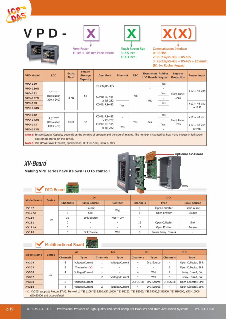
PAC Products
2-19 ICP DAS CO., LTD. Professional Provider of High Quality Industrial Computer Products and Data Acquisition Systems Vol. FPC 1.0.00
x(x)
VPD Model LCDExtra Flash
Image Storage Capacity
Com Port Ethernet RTCExpansion I/O Boards
Rubber Keypad
Ingress Protection
Power Input
VPD-130
3.5" TFT (Resolution 320 x 240)
8 MB54
RS-232/RS-485
-
Yes
- Yes
Front Panel: IP65
+12 ~ 48 VDCVPD-130N - -
VPD-132COM1: RS-485 or RS-232COM2: RS-485
Yes
Yes
VPD-132N -
VPD-133Yes
Yes +12 ~ 48 VDC
or PoEVPD-133N -
VPD-1424.3" TFT
(Resolution 480 x 272)
8 MB 32
COM1: RS-485 or RS-232COM2: RS-485 or RS-232
-
Yes Yes
Yes
Front Panel: IP65
+12 ~ 48 VDCVPD-142N -
VPD-143Yes
Yes +12 ~ 48 VDC
or PoEVPD-143N -
Note1: Image Storage Capacity depends on the content of program and the size of images. The number is counted by how many images in full screen
size can be stored on the device.
Note2: PoE (Power over Ethernet) specifi cation: IEEE 802.3af, Class 1, 48 V
V P D - x xTouch Screen SizeTouch Screen Size3: 3.5 inch3: 3.5 inch4: 4.3 inch4: 4.3 inch
Form FactorForm Factor1: 103 × 103 mm Panel Mount 1: 103 × 103 mm Panel Mount
Communication Interface Communication Interface 0: RS-485 0: RS-485 2: RS-232/RS-485 + RS-4852: RS-232/RS-485 + RS-4853: RS-232/RS-485 + RS-485 + Ethernet3: RS-232/RS-485 + RS-485 + Ethernet(N): No Rubber Keypad(N): No Rubber Keypad
DIO Board
Multifunctional Board
Optional XV-Board
XV-Board Making VPD series have its own I/O to control!
Model Name SeriesDI DO
Channels Sink/Source Contact Channels Type Sink/Source
XV107
XV
8 SourceWet
8 Open Collector Sink/Source
XV107A 8 Sink 8 Open Emitter Source
XV110 16 Sink/Source Wet + Dry - - -
XV111 0 - - 16 Open Collector Sink
XV111A 0 - - 16 Open Emitter Source
XV116 5 Sink/Source Wet 6 Power Relay, Form A -
Model Name SeriesAI AO DI DO
Channels Type Channels Type Channels Type Channels Type
XV304
XV
6 Voltage/Current 1 Voltage/Current 4 Dry, Source 4 Open Collector, Sink
XV305 8 Thermistor (*) - - - - 8 Open Collector, Sink
XV306 4 Voltage/Current - - 4 Wet 4 Relay, FormA, 6A
XV307 - - 2 Voltage/Current 4 Wet 4 Relay, FormA, 6A
XV308 8 Voltage/Current - - DI+DO=8 Dry, Source DI+DO=8 Open Collector, Sink
XV310 4 Voltage/Current 2 Voltage/Current 4 Dry, Source 4 Open Collector, Sink
(*): XV305i supports Precon ST-A3, Fenwell U, YSI L100,YSI L300,YSI L1000, YSI B2252, YSI B3000, YSI B5000,SI B6000, YSI B10000, YSI H10000, YSIH30000 and User-defined
Optional

PAC Products
2-20E-mail: [email protected] Vol. FPC 1.0.00
Website: http://www.icpdas.com
PA
C P
rodu
cts
Pan
el P
rodu
cts
Rem
ote
I/O
M
odul
e an
d U
nit
DA
Q C
ard
Indu
stri
al
Com
mun
icat
ion
Wir
eles
s So
luti
onM
otio
n
Au
tom
atio
nA
cces
sori
esEn
ergy
M
anag
emen
tSo
luti
on
HMI for Small Instruments HMI on Large Machines
Smart Home Automation Infrared Device Integration
TPD/VPD Series Applications
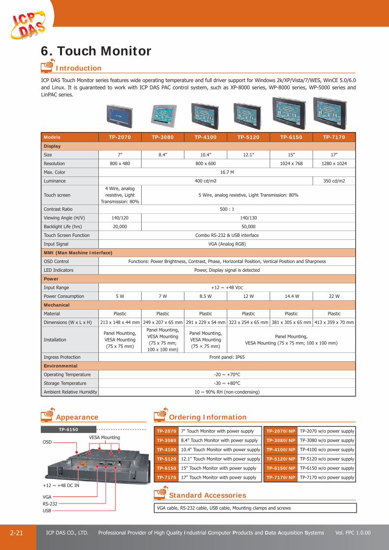
PAC Products
2-21 ICP DAS CO., LTD. Professional Provider of High Quality Industrial Computer Products and Data Acquisition Systems Vol. FPC 1.0.00
6. Touch Monitor
TP-6150
Models TP-2070 TP-3080 TP-4100 TP-5120 TP-6150 TP-7170
Display
Size 7” 8.4” 10.4” 12.1” 15” 17"
Resolution 800 x 480 800 x 600 1024 x 768 1280 x 1024
Max. Color 16.7 M
Luminance 400 cd/m2 350 cd/m2
Touch screen4 Wire, analog resistive, Light
Transmission: 80%5 Wire, analog resistive, Light Transmission: 80%
Contrast Ratio 500 : 1
Viewing Angle (H/V) 140/120 140/130
Backlight Life (hrs) 20,000 50,000
Touch Screen Function Combo RS-232 & USB interface
Input Signal VGA (Analog RGB)
MMI (Man Machine Interface)
OSD Control Functions: Power Brightness, Contrast, Phase, Horizontal Position, Vertical Position and Sharpness
LED Indicators Power, Display signal is detected
Power
Input Range +12 ~ +48 VDC
Power Consumption 5 W 7 W 8.5 W 12 W 14.4 W 22 W
Mechanical
Material Plastic Plastic Plastic Plastic Plastic Plastic
Dimensions (W x L x H) 213 x 148 x 44 mm 249 x 207 x 65 mm 291 x 229 x 54 mm 323 x 254 x 65 mm 381 x 305 x 65 mm 413 x 359 x 70 mm
InstallationPanel Mounting, VESA Mounting(75 x 75 mm)
Panel Mounting, VESA Mounting(75 x 75 mm;
100 x 100 mm)
Panel Mounting, VESA Mounting(75 × 75 mm)
Panel Mounting,VESA Mounting (75 x 75 mm; 100 x 100 mm)
Ingress Protection Front panel: IP65
Environmental
Operating Temperature -20 ~ +70°C
Storage Temperature -30 ~ +80°C
Ambient Relative Humidity 10 ~ 90% RH (non-condensing)
ICP DAS Touch Monitor series features wide operating temperature and full driver support for Windows 2k/XP/Vista/7/WES, WinCE 5.0/6.0 and Linux. It is guaranteed to work with ICP DAS PAC control system, such as XP-8000 series, WP-8000 series, WP-5000 series and LinPAC series.
USB
OSD
RS-232VGA
VESA Mounting
+12 ~ +48 DC IN
VGA cable, RS-232 cable, USB cable, Mounting clamps and screws
TP-2070 7" Touch Monitor with power supply
TP-3080 8.4" Touch Monitor with power supply
TP-4100 10.4" Touch Monitor with power supply
TP-5120 12.1" Touch Monitor with power supply
TP-6150 15" Touch Monitor with power supply
TP-7170 17" Touch Monitor with power supply
TP-2070/NP TP-2070 w/o power supply
TP-3080/NP TP-3080 w/o power supply
TP-4100/NP TP-4100 w/o power supply
TP-5120/NP TP-5120 w/o power supply
TP-6150/NP TP-6150 w/o power supply
TP-7170/NP TP-7170 w/o power supply
Introduction
Appearance Ordering Information
Standard Accessories
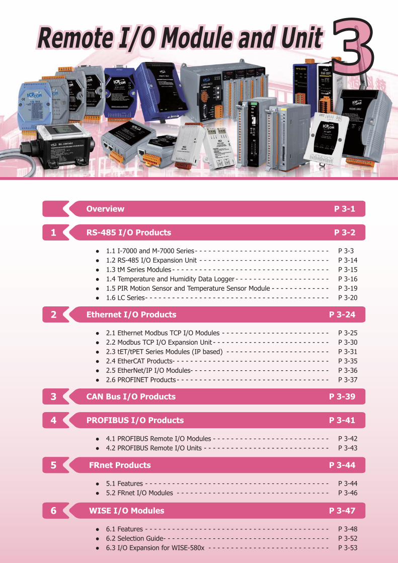
Overview P 3-1
CAN Bus I/O Products P 3-39
PROFIBUS I/O Products P 3-41
FRnet Products P 3-44
WISE I/O Modules P 3-47
3
4
5
6
● 4.1 PROFIBUS Remote I/O Modules - - - - - - - - - - - - - - - - - - - - - - - - - - P 3-42 ● 4.2 PROFIBUS Remote I/O Units - - - - - - - - - - - - - - - - - - - - - - - - - - - - P 3-43
● 5.1 Features - - - - - - - - - - - - - - - - - - - - - - - - - - - - - - - - - - - - - - - - - P 3-44 ● 5.2 FRnet I/O Modules - - - - - - - - - - - - - - - - - - - - - - - - - - - - - - - - - - P 3-46
● 6.1 Features - - - - - - - - - - - - - - - - - - - - - - - - - - - - - - - - - - - - - - - - - P 3-48 ● 6.2 Selection Guide - - - - - - - - - - - - - - - - - - - - - - - - - - - - - - - - - - - - - P 3-52 ● 6.3 I/O Expansion for WISE-580x - - - - - - - - - - - - - - - - - - - - - - - - - - - P 3-53
Ethernet I/O Products P 3-242
● 2.1 Ethernet Modbus TCP I/O Modules - - - - - - - - - - - - - - - - - - - - - - - - P 3-25 ● 2.2 Modbus TCP I/O Expansion Unit - - - - - - - - - - - - - - - - - - - - - - - - - - P 3-30 ● 2.3 tET/tPET Series Modules (IP based) - - - - - - - - - - - - - - - - - - - - - - - P 3-31 ● 2.4 EtherCAT Products- - - - - - - - - - - - - - - - - - - - - - - - - - - - - - - - - - - P 3-35 ● 2.5 EtherNet/IP I/O Modules- - - - - - - - - - - - - - - - - - - - - - - - - - - - - - - P 3-36 ● 2.6 PROFINET Products - - - - - - - - - - - - - - - - - - - - - - - - - - - - - - - - - - P 3-37
RS-485 I/O Products P 3-21
● 1.1 I-7000 and M-7000 Series - - - - - - - - - - - - - - - - - - - - - - - - - - - - - - P 3-3 ● 1.2 RS-485 I/O Expansion Unit - - - - - - - - - - - - - - - - - - - - - - - - - - - - - P 3-14 ● 1.3 tM Series Modules - - - - - - - - - - - - - - - - - - - - - - - - - - - - - - - - - - - P 3-15 ● 1.4 Temperature and Humidity Data Logger - - - - - - - - - - - - - - - - - - - - - P 3-16 ● 1.5 PIR Motion Sensor and Temperature Sensor Module - - - - - - - - - - - - - P 3-19 ● 1.6 LC Series - - - - - - - - - - - - - - - - - - - - - - - - - - - - - - - - - - - - - - - - - P 3-20
Remote I/O Module and UnitRemote I/O Module and Unit 3
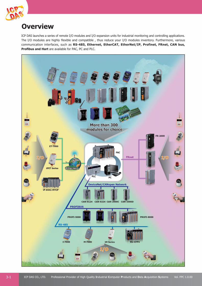
PAC Products
3-1 ICP DAS CO., LTD. Professional Provider of High Quality Industrial Computer Products and Data Acquisition Systems Vol. FPC 1.0.00
OverviewICP DAS launches a series of remote I/O modules and I/O expansion units for industrial monitoring and controlling applications. The I/O modules are highly flexible and compatible , thus reduce your I/O modules inventory. Furthermore, various communication interfaces, such as RS-485, Ethernet, EtherCAT, EtherNet/IP, Profinet, FRnet, CAN bus, Profi bus and Hart are available for PAC, PC and PLC.
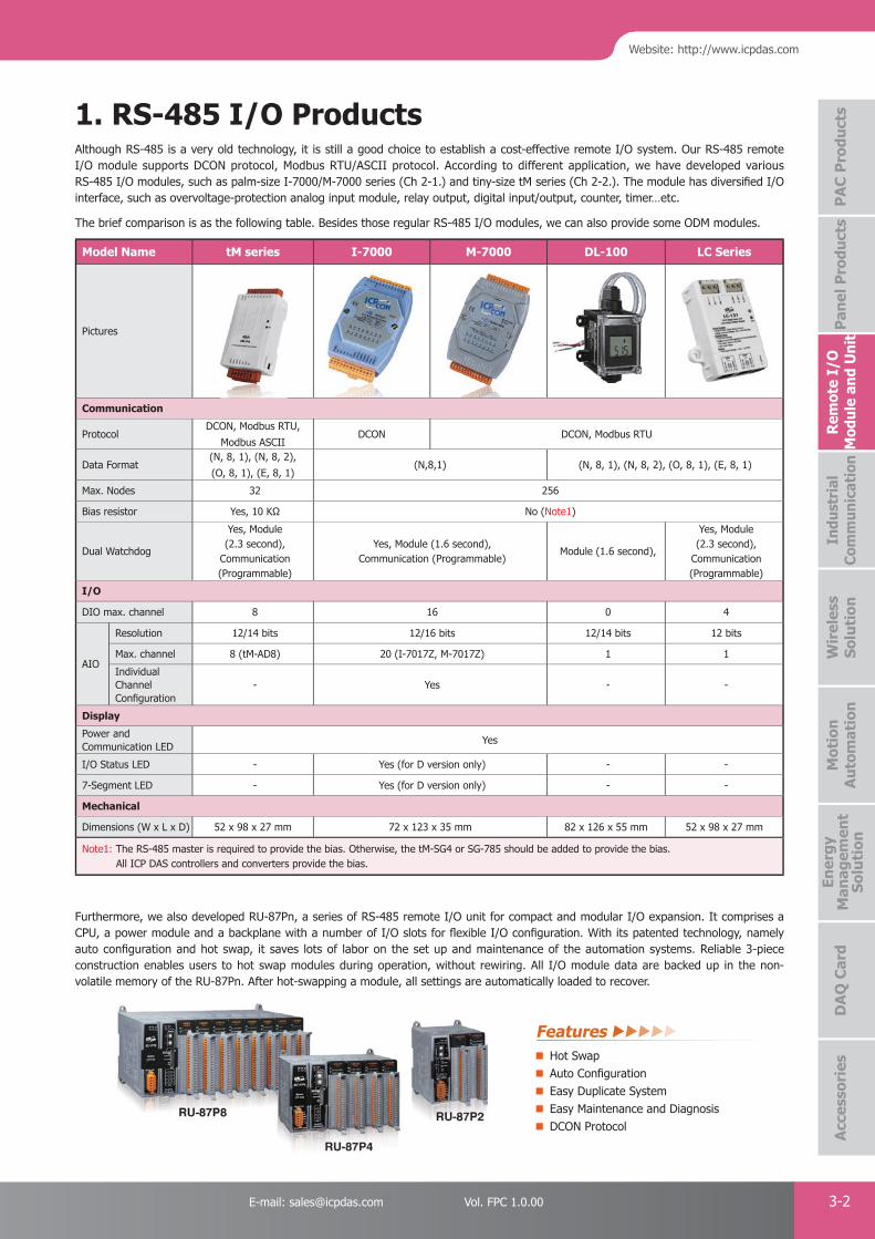
PAC Products
3-2E-mail: [email protected] Vol. FPC 1.0.00
Website: http://www.icpdas.com
PA
C P
rodu
cts
Pan
el P
rodu
cts
Rem
ote
I/O
M
odul
e an
d U
nit
DA
Q C
ard
Indu
stri
al
Com
mun
icat
ion
Wir
eles
s So
luti
onM
otio
n
Au
tom
atio
nA
cces
sori
esEn
ergy
M
anag
emen
tSo
luti
on
Model Name tM series I-7000 M-7000 DL-100 LC Series
Pictures
Communication
ProtocolDCON, Modbus RTU,
Modbus ASCIIDCON DCON, Modbus RTU
Data Format(N, 8, 1), (N, 8, 2),
(O, 8, 1), (E, 8, 1)(N,8,1) (N, 8, 1), (N, 8, 2), (O, 8, 1), (E, 8, 1)
Max. Nodes 32 256
Bias resistor Yes, 10 KΩ No (Note1)
Dual Watchdog
Yes, Module (2.3 second),
Communication (Programmable)
Yes, Module (1.6 second), Communication (Programmable)
Module (1.6 second),
Yes, Module (2.3 second),
Communication (Programmable)
I/O
DIO max. channel 8 16 0 4
AIO
Resolution 12/14 bits 12/16 bits 12/14 bits 12 bits
Max. channel 8 (tM-AD8) 20 (I-7017Z, M-7017Z) 1 1
Individual Channel Confi guration
- Yes - -
Display
Power and Communication LED
Yes
I/O Status LED - Yes (for D version only) - -
7-Segment LED - Yes (for D version only) - -
Mechanical
Dimensions (W x L x D) 52 x 98 x 27 mm 72 x 123 x 35 mm 82 x 126 x 55 mm 52 x 98 x 27 mm
Note1: The RS-485 master is required to provide the bias. Otherwise, the tM-SG4 or SG-785 should be added to provide the bias. All ICP DAS controllers and converters provide the bias.
Furthermore, we also developed RU-87Pn, a series of RS-485 remote I/O unit for compact and modular I/O expansion. It comprises a CPU, a power module and a backplane with a number of I/O slots for fl exible I/O confi guration. With its patented technology, namely auto confi guration and hot swap, it saves lots of labor on the set up and maintenance of the automation systems. Reliable 3-piece construction enables users to hot swap modules during operation, without rewiring. All I/O module data are backed up in the non-volatile memory of the RU-87Pn. After hot-swapping a module, all settings are automatically loaded to recover.
Although RS-485 is a very old technology, it is still a good choice to establish a cost-effective remote I/O system. Our RS-485 remote I/O module supports DCON protocol, Modbus RTU/ASCII protocol. According to different application, we have developed various RS-485 I/O modules, such as palm-size I-7000/M-7000 series (Ch 2-1.) and tiny-size tM series (Ch 2-2.). The module has diversifi ed I/O interface, such as overvoltage-protection analog input module, relay output, digital input/output, counter, timer…etc.
The brief comparison is as the following table. Besides those regular RS-485 I/O modules, we can also provide some ODM modules.
Hot SwapAuto Confi gurationEasy Duplicate SystemEasy Maintenance and DiagnosisDCON Protocol
1. RS-485 I/O Products
Features

PAC Products
3-3 ICP DAS CO., LTD. Professional Provider of High Quality Industrial Computer Products and Data Acquisition Systems Vol. FPC 1.0.00
I-7000 and M-7000 remote I/O modules provide cost-effective protection and conditioning for a wide range of valuable industrial control system. The product line includes sensor-to-computer, computer-to-sensor, digital I/O, timer/ counter, RS-232 to RS-485 converter, USB to RS-485 converter, RS-485 repeater, RS-485 hub and RS-232/422/485 to Fiber Optics. I-7000 supports DCON protocol, and M-7000 modules support Modbus RTU and DCON protocols. Many SCADA/HMI software and PLCs support Modbus RTU protocol. It is easy for them to integrate with M-7000 modules.
Factory automation, machine automation, testing equipment, building automation, solar energy system, pollution monitoring system, heating chamber…etc
RS-485 Industrial Multi-Drop NetworkI-7000/M-7000 series modules use the industrial EIA RS-485 communication interface to transmit and receive data at high speed over long distance. All modules are easy to integrate to the regular computer and controller. Internal surge protection circuitry is used on data lines to protect the modules from spikes.
I/O type and Range ProgrammableThe analog modules support several types and ranges which can be selected remotely by issuing command from the host.
Easy Mounting and Connection The user may mount the modules on a DIN rail or piggyback.
Rugged Industrial EnvironmentI-7000 and M-7000 modules provide module watchdog and host watchdog. The module watchdog is a hardware watchdog designed to automatically reset the micro-processor when the module hangs. The host watchdog is a software watchdog that monitors the communication status of the host controller, such as PC, PLC and PAC. The output of module will go to the safe value state when the host fails to prevent any erroneous operations. The Dual Watchdog design ensures higher reliability and stability.
● Programmable Power-on Value and Safe ValueThe DO and AO I/O modules provide programmable power-on value and safe value. When the host watchdog is active, the DO and AO output go to the pre-confi gured safe value.
1.1 I-7000 and M-7000 Series
Applications
Features
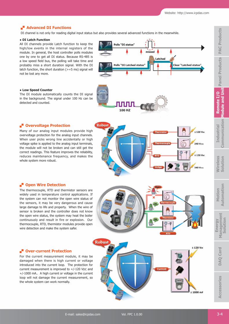
PAC Products
3-4E-mail: [email protected] Vol. FPC 1.0.00
Website: http://www.icpdas.com
PA
C P
rodu
cts
Pan
el P
rodu
cts
Rem
ote
I/O
M
odul
e an
d U
nit
DA
Q C
ard
Indu
stri
al
Com
mun
icat
ion
Wir
eles
s So
luti
onM
otio
n
Au
tom
atio
nA
cces
sori
esEn
ergy
M
anag
emen
tSo
luti
on
Advanced DI FunctionsDI channel is not only for reading digital input status but also provides several advanced functions in the meanwhile.
● DI Latch FunctionAll DI channels provide Latch function to keep the high/low events in the internal registers of the module. In general, the host controller polls modules one by one to get all DI status. Because RS-485 is a low speed fi eld bus, the polling will take time and probably miss a short duration signal. With the DI latch function, the short duration (>=5 ms) signal will not be lost any more.
Overvoltage ProtectionMany of our analog input modules provide high overvoltage protection for the analog input channels. When user picks wrong line accidentally or high voltage spike is applied to the analog input terminals, the module will not be broken and can still get the correct readings. This feature improves the reliability, reduces maintenance frequency, and makes the whole system more robust.
Open Wire DetectionThe thermocouple, RTD and thermistor sensors are widely used in temperature control applications. If the system can not monitor the open wire status of the sensors, it may be very dangerous and cause large damage to life and property. When the wire of sensor is broken and the controller does not know the open wire status, the system may heat the boiler continuously and result in fire or explosion. Our thermocouple, RTD, thermistor modules provide open wire detection and make the system safer.
Over-current ProtectionFor the current measurement module, it may be damaged when there is high current or voltage introduced into the current loop. The protection for current measurement is improved to +/-120 VDC and +/-1000 mA.. A high current or voltage in the current loop will not damage the current measurement, so the whole system can work normally.
● Low Speed Counter The DI module automatically counts the DI signal in the background. The signal under 100 Hz can be detected and counted.
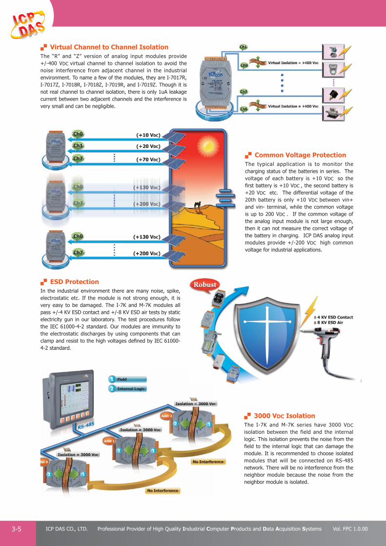
PAC Products
3-5 ICP DAS CO., LTD. Professional Provider of High Quality Industrial Computer Products and Data Acquisition Systems Vol. FPC 1.0.00
Virtual Channel to Channel IsolationThe “R” and “Z” version of analog input modules provide +/-400 VDC virtual channel to channel isolation to avoid the noise interference from adjacent channel in the industrial environment. To name a few of the modules, they are I-7017R, I-7017Z, I-7018R, I-7018Z, I-7019R, and I-7019Z. Though it is not real channel to channel isolation, there is only 1uA leakage current between two adjacent channels and the interference is very small and can be negligible.
Common Voltage ProtectionThe typical application is to monitor the charging status of the batteries in series. The voltage of each battery is +10 VDC so the fi rst battery is +10 VDC , the second battery is +20 VDC etc. The differential voltage of the 20th battery is only +10 VDC between vin+ and vin- terminal, while the common voltage is up to 200 VDC . If the common voltage of the analog input module is not large enough, then it can not measure the correct voltage of the battery in charging. ICP DAS analog input modules provide +/-200 VDC high common voltage for industrial applications.
3000 VDC IsolationThe I-7K and M-7K series have 3000 VDC isolation between the field and the internal logic. This isolation prevents the noise from the fi eld to the internal logic that can damage the module. It is recommended to choose isolated modules that will be connected on RS-485 network. There will be no interference from the neighbor module because the noise from the neighbor module is isolated.
ESD ProtectionIn the industrial environment there are many noise, spike, electrostatic etc. If the module is not strong enough, it is very easy to be damaged. The I-7K and M-7K modules all pass +/-4 KV ESD contact and +/-8 KV ESD air tests by static electricity gun in our laboratory. The test procedures follow the IEC 61000-4-2 standard. Our modules are immunity to the electrostatic discharges by using components that can clamp and resist to the high voltages defi ned by IEC 61000-4-2 standard.

PAC Products
3-6E-mail: [email protected] Vol. FPC 1.0.00
Website: http://www.icpdas.com
PA
C P
rodu
cts
Pan
el P
rodu
cts
Rem
ote
I/O
M
odul
e an
d U
nit
DA
Q C
ard
Indu
stri
al
Com
mun
icat
ion
Wir
eles
s So
luti
onM
otio
n
Au
tom
atio
nA
cces
sori
esEn
ergy
M
anag
emen
tSo
luti
on
Stack Mounting
1. Installation
2. Dimensions (Units: mm)p
40.625.6
101
58.1
72
34
72
101
58.1
72
3335
.4
122
122
55.6
55.6
Ø4.5
35.4
88.5
3434
55.6
833
Bottom View
Top View
Front View
DIN-Rail Mounting
Front View Left Side View Rear ViewRight Side View
Dual Communication ProtocolsAll I-7000 and M-7000 modules use a simple command /response protocol for communication. M-7000 also supports the industrial standard Modbus RTU protocol. The user can use high-level language, such as C, VB, Delphi, and others to write their application programs. Some famous software package can control I-7000 and M-7000 directly, such as LabVIEW, InduSoft, TRACE MODE, EZ data logger, EZ Prog..etc. I-7000: supports DCON protocolM-7000: supports Modbus RTU and DCON protocols
Self-Tuner Inside"Self-Tuner" is a patented ASIC. It auto-tunes the baud rate and data format in whole RS-485 network, and auto-handles the direction of the RS-485 communication line. Since the unique features of this ASIC, the user can implement a very fl exible remote I/O confi guration via the RS-485 network.
Expandable NetworkI-7510 repeater is more than a pure isolated repeater. "Self-Tuner" ASIC is built-in. It has some outstanding features, such as 3000V isolation, 115K max. speed, variable baud rate and data format. Each I-7510 repeater can let you extend the network to another 4,000 ft long. Actually the user should consider the network length and the hardware loading effect and use I-7510 to isolate different groups to avoid high voltage hitting the whole system through a single communication network.
Hardware
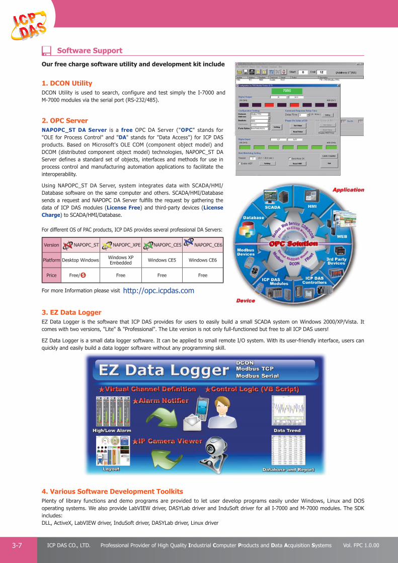
PAC Products
3-7 ICP DAS CO., LTD. Professional Provider of High Quality Industrial Computer Products and Data Acquisition Systems Vol. FPC 1.0.00
2. OPC Server NAPOPC_ST DA Server is a free OPC DA Server ("OPC" stands for "OLE for Process Control" and "DA" stands for "Data Access") for ICP DAS products. Based on Microsoft's OLE COM (component object model) and DCOM (distributed component object model) technologies, NAPOPC_ST DA Server defines a standard set of objects, interfaces and methods for use in process control and manufacturing automation applications to facilitate the interoperability.
Using NAPOPC_ST DA Server, system integrates data with SCADA/HMI/Database software on the same computer and others. SCADA/HMI/Database sends a request and NAPOPC DA Server fulfi lls the request by gathering the data of ICP DAS modules (License Free) and third-party devices (License Charge) to SCADA/HMI/Database.
For different OS of PAC products, ICP DAS provides several professional DA Servers:
3. EZ Data LoggerEZ Data Logger is the software that ICP DAS provides for users to easily build a small SCADA system on Windows 2000/XP/Vista. It comes with two versions, "Lite" & "Professional". The Lite version is not only full-functioned but free to all ICP DAS users! EZ Data Logger is a small data logger software. It can be applied to small remote I/O system. With its user-friendly interface, users can quickly and easily build a data logger software without any programming skill.
4. Various Software Development ToolkitsPlenty of library functions and demo programs are provided to let user develop programs easily under Windows, Linux and DOS operating systems. We also provide LabVIEW driver, DASYLab driver and InduSoft driver for all I-7000 and M-7000 modules. The SDK includes:DLL, ActiveX, LabVIEW driver, InduSoft driver, DASYLab driver, Linux driver
For more Information please visit http://opc.icpdas.com
Our free charge software utility and development kit include
1. DCON Utility DCON Utility is used to search, configure and test simply the I-7000 and M-7000 modules via the serial port (RS-232/485).
Version NAPOPC_ST NAPOPC_XPE NAPOPC_CE5 NAPOPC_CE6
Platform Desktop Windows Windows XP Embedded Windows CE5 Windows CE6
Price Free/ Free Free Free
Software Support

PAC Products
3-8E-mail: [email protected] Vol. FPC 1.0.00
Website: http://www.icpdas.com
PA
C P
rodu
cts
Pan
el P
rodu
cts
Rem
ote
I/O
M
odul
e an
d U
nit
DA
Q C
ard
Indu
stri
al
Com
mun
icat
ion
Wir
eles
s So
luti
onM
otio
n
Au
tom
atio
nA
cces
sori
esEn
ergy
M
anag
emen
tSo
luti
on
Model Name
Analog Input
Digital I/OChannels Resolution
Sampling Rate
(total)
Voltage and Current Input
CommonVoltage
Protection
Individual Channel
Confi gurable
Overvoltage Protection
I-7012I-7012D
1 diff.
16-bit
10 Hz
±150 mV±500 mV
±1 V±5 V±10 V
±20 mA (Note1)±100 VDC
-
±100 VDC
DI x 1 (Note3)
DO x 2 (Note4)
I-7012FI-7012FD
10/100 Hz
±150 mV±500 mV
±1 V±5 V±10 V
±20 mA (Note1)
I-7017 M-7017
8 diff.
10 Hz
±150 mV±500 mV
±1 V±5 V±10 V
±20 mA (Note1)
±35 VDC
±120 VDC
-
I-7017C M-7017C0 ~ 20 mA4 ~ 20 mA
±20 mA (Note2)±100 VDC
I-7017F
10/60 Hz
±150 mV±500 mV
±1 V±5 V±10 V
±20 mA (Note1)
±120 VDC
I-7017FC0 ~ 20 mA4 ~ 20 mA
±20 mA (Note2)±100 VDC
I-7017R M-7017R
±150 mV±500 mV
±1 V±5 V±10 V
±20 mA (Note1)
±200 VDC
Yes(Note6) ±240 Vrms
I-7017R-A5 M-7017R-A5 10/50 Hz±50 V ±150 V
-
200 VDC
I-7017RC M-7017RC 10/60 Hz0 ~ 20 mA4 ~ 20 mA
±20 mA (Note2)±100 VDC
M-7017RMS 10 Hz
0 ~ +10 Vrms, 0 ~ +5 Vrms, 0 ~ 1 Vrms,
0 ~ 500 mVrms, 0 ~ 150 mVrms
±35 VDC
I-7017Z M-7017Z 10 diff. or 20 SE 10/60 Hz
±150 mV±500 mV
±1 V±5 V±10 V
0 ~ 20 mA4 ~ 20 mA
±20 mA (Note5)
Yes 240 Vrms (diff.)150 Vrms (SE)
Note1: Need external 125 Ω resistors.Note2: Doesn't need external 125 Ω resistors. Note3: Can be used as DI or low speed (50 Hz) counter.Note4: Can be used as DO or High/Low Alarm.Note5: Jumper selectable.Note6: Only available with the fi rmware version of 7017R series is B3.9 and later.
Voltage & Current Input
Selection Guide
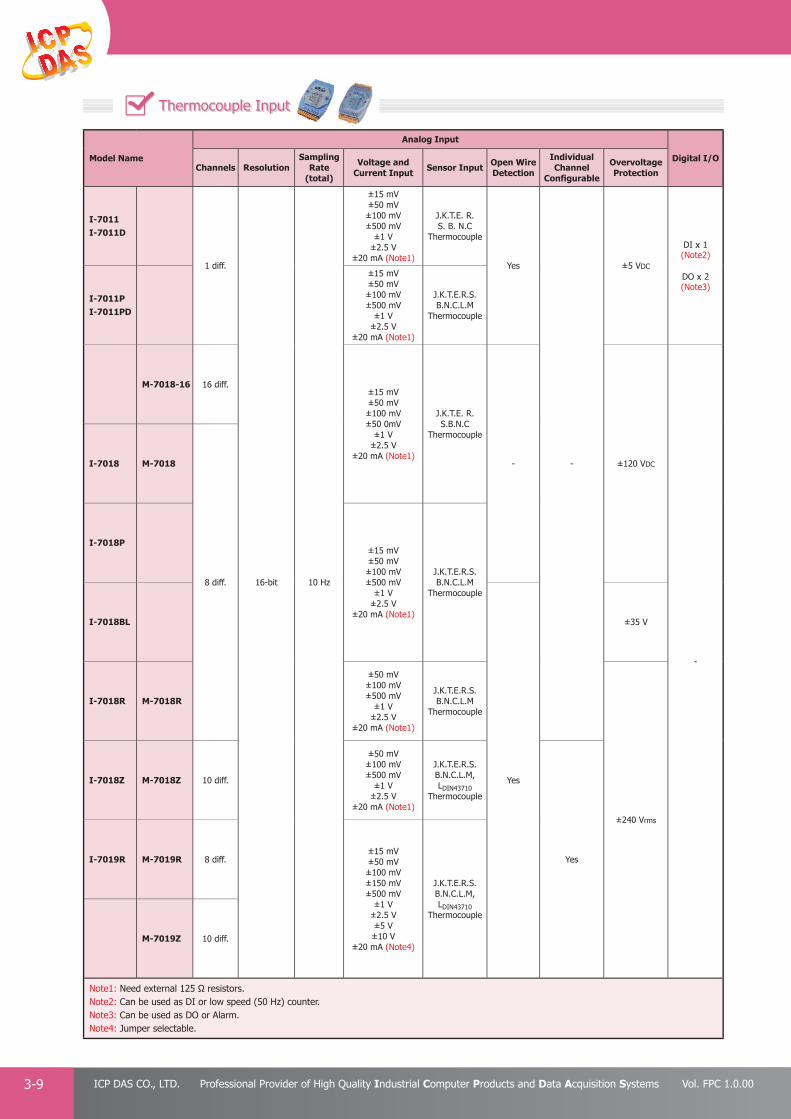
PAC Products
3-9 ICP DAS CO., LTD. Professional Provider of High Quality Industrial Computer Products and Data Acquisition Systems Vol. FPC 1.0.00
Model Name
Analog Input
Digital I/OChannels Resolution
Sampling Rate
(total)
Voltage and Current Input Sensor Input Open Wire
Detection
Individual Channel
Confi gurable
Overvoltage Protection
I-7011I-7011D
1 diff.
16-bit 10 Hz
±15 mV±50 mV±100 mV±500 mV
±1 V±2.5 V
±20 mA (Note1)
J.K.T.E. R.S. B. N.C
Thermocouple
Yes
-
±5 VDC
DI x 1 (Note2)
DO x 2 (Note3)
I-7011PI-7011PD
±15 mV±50 mV±100 mV±500 mV
±1 V±2.5 V
±20 mA (Note1)
J.K.T.E.R.S.B.N.C.L.M
Thermocouple
M-7018-16 16 diff.±15 mV±50 mV±100 mV±50 0mV
±1 V±2.5 V
±20 mA (Note1)
J.K.T.E. R.S.B.N.C
Thermocouple
- ±120 VDC
-
I-7018 M-7018
8 diff.
I-7018P±15 mV±50 mV±100 mV±500 mV
±1 V±2.5 V
±20 mA (Note1)
J.K.T.E.R.S.B.N.C.L.M
Thermocouple
I-7018BL
Yes
±35 V
I-7018R M-7018R
±50 mV±100 mV±500 mV
±1 V±2.5 V
±20 mA (Note1)
J.K.T.E.R.S.B.N.C.L.M
Thermocouple
±240 Vrms
I-7018Z M-7018Z 10 diff.
±50 mV±100 mV±500 mV
±1 V±2.5 V
±20 mA (Note1)
J.K.T.E.R.S.B.N.C.L.M, LDIN43710
Thermocouple
YesI-7019R M-7019R 8 diff.±15 mV±50 mV±100 mV±150 mV±500 mV
±1 V±2.5 V±5 V±10 V
±20 mA (Note4)
J.K.T.E.R.S.B.N.C.L.M, LDIN43710
Thermocouple
M-7019Z 10 diff.
Note1: Need external 125 Ω resistors.Note2: Can be used as DI or low speed (50 Hz) counter.Note3: Can be used as DO or Alarm.Note4: Jumper selectable.
Thermocouple Input
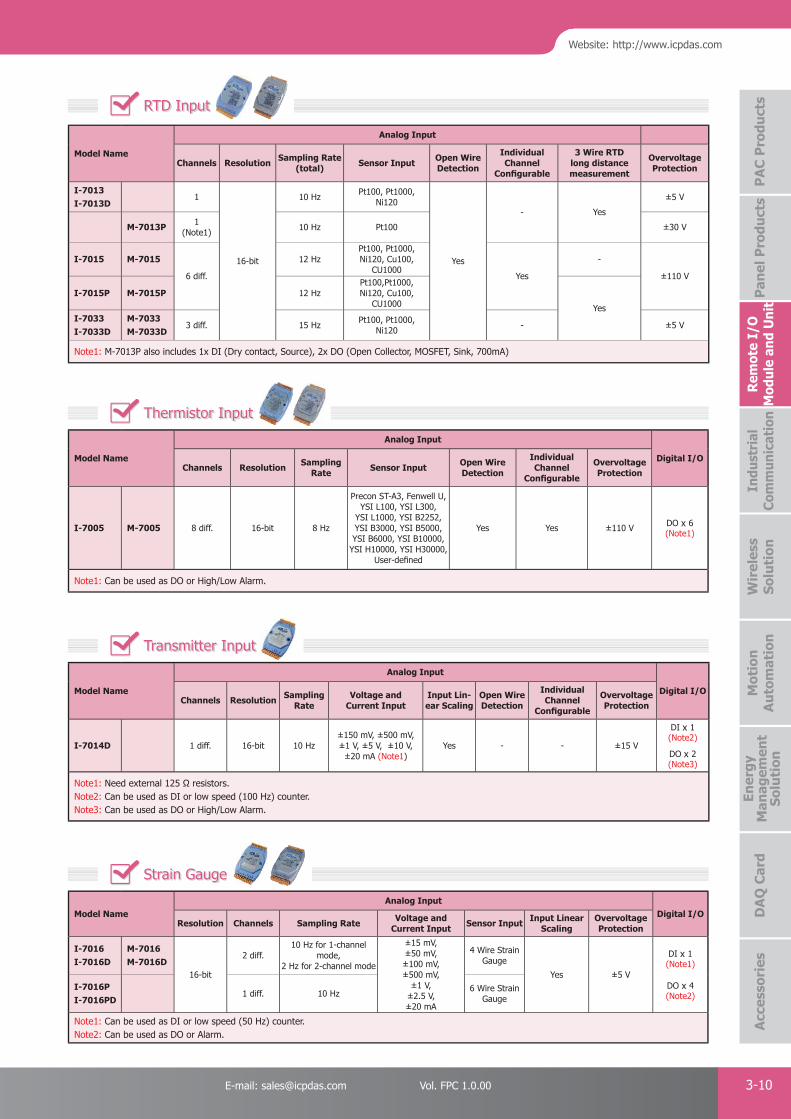
PAC Products
3-10E-mail: [email protected] Vol. FPC 1.0.00
Website: http://www.icpdas.com
PA
C P
rodu
cts
Pan
el P
rodu
cts
Rem
ote
I/O
M
odul
e an
d U
nit
DA
Q C
ard
Indu
stri
al
Com
mun
icat
ion
Wir
eles
s So
luti
onM
otio
n
Au
tom
atio
nA
cces
sori
esEn
ergy
M
anag
emen
tSo
luti
on
Model Name
Analog Input
Channels Resolution Sampling Rate(total) Sensor Input Open Wire
Detection
Individual Channel
Confi gurable
3 Wire RTD long distance measurement
Overvoltage Protection
I-7013I-7013D
1
16-bit
10 Hz Pt100, Pt1000,Ni120
Yes
- Yes
±5 V
M-7013P 1 (Note1) 10 Hz Pt100 ±30 V
I-7015 M-7015
6 diff.
12 HzPt100, Pt1000,Ni120, Cu100,
CU1000Yes
-
±110 V
I-7015P M-7015P 12 HzPt100,Pt1000,Ni120, Cu100,
CU1000 YesI-7033I-7033D
M-7033M-7033D
3 diff. 15 Hz Pt100, Pt1000,Ni120 - ±5 V
Note1: M-7013P also includes 1x DI (Dry contact, Source), 2x DO (Open Collector, MOSFET, Sink, 700mA)
Model Name
Analog Input
Digital I/OChannels Resolution Sampling
Rate Sensor Input Open Wire Detection
Individual Channel
Confi gurable
Overvoltage Protection
I-7005 M-7005 8 diff. 16-bit 8 Hz
Precon ST-A3, Fenwell U, YSI L100, YSI L300,
YSI L1000, YSI B2252, YSI B3000, YSI B5000, YSI B6000, YSI B10000,
YSI H10000, YSI H30000, User-defi ned
Yes Yes ±110 V DO x 6 (Note1)
Note1: Can be used as DO or High/Low Alarm.
Model Name
Analog Input
Digital I/OChannels Resolution Sampling
RateVoltage and
Current InputInput Lin-ear Scaling
Open Wire Detection
Individual Channel
Confi gurable
Overvoltage Protection
I-7014D 1 diff. 16-bit 10 Hz±150 mV, ±500 mV, ±1 V, ±5 V, ±10 V,
±20 mA (Note1)Yes - - ±15 V
DI x 1 (Note2)
DO x 2 (Note3)
Note1: Need external 125 Ω resistors.Note2: Can be used as DI or low speed (100 Hz) counter. Note3: Can be used as DO or High/Low Alarm.
RTD Input
Thermistor Input
Transmitter Input
Model Name Analog Input
Digital I/OResolution Channels Sampling Rate Voltage and
Current Input Sensor Input Input Linear Scaling
Overvoltage Protection
I-7016I-7016D
M-7016M-7016D
16-bit
2 diff.10 Hz for 1-channel
mode,2 Hz for 2-channel mode
±15 mV, ±50 mV,±100 mV, ±500 mV,
±1 V, ±2.5 V,±20 mA
4 Wire Strain Gauge
Yes ±5 V
DI x 1 (Note1)
DO x 4 (Note2)
I-7016PI-7016PD
1 diff. 10 Hz 6 Wire Strain Gauge
Note1: Can be used as DI or low speed (50 Hz) counter. Note2: Can be used as DO or Alarm.
Strain Gauge

PAC Products
3-11 ICP DAS CO., LTD. Professional Provider of High Quality Industrial Computer Products and Data Acquisition Systems Vol. FPC 1.0.00
Model Name Analog Output
Resolution Channels Voltage Output Current Output Safe Value Power-on Value
I-7021 12-bit1
0 ~ 10 V
0 ~ 20 mA4 ~ 20 mA Yes Yes
I-7021P 16-bit
I-7022 M-7022 12-bit 2 (Note1)
I-7024 M-702414-bit
4
±10 V, 0 ~ 10 V,
±5 V,0-5 V
M-7024R 4(Note2)
M-7024UM-7024UD
(Note3)16-bit 4
(Note4)
M-7028 12-bit 8
Note1: Channel-to-channel isolation.Note2: M-7024R also includes 5 channel DI (Dry Contact).Note3: M-7024UD includes LED for DI and DO status.Note4: M-7024U and M-7024UD also include 4x DI(Dry and Wet contact)
Model Name Analog Input Analog Output DC Input DC Output
Channels Voltage and Current Input Channels Voltage and
Current Output Channels ON Voltage Level Output type Max Load Current
M-7002 4 ±150 mV, ±500 mV
±1 V, ±5 V, ±10 V0 ~ 20 mA, 4 ~ 20 mA,
±20 mA (Note1)
- -5 10 ~ 50 VDC Power Relay
(Form A) 5 A @ 250 VAC/30 VDCM-7003 8 - -
M-7026 6 2
±10 V, 0 ~ 10 V,±5 V ,0 ~ 5 V,
0 ~ 20 mA,4 ~ 20 mA
(Note1)
3 Connect to GND Open Collector x 3 Sink, 700 mA
Note1: Jumper selectable.
Model Name DC Input
Channels (Note1) Type ON Voltage Level OFF Voltage Level Isolation Voltage
I-7041I-7041D
M-7041M-7041D
14 (Sink/Source) Common Source
+4 ~ +30 V +1 V Max.
3750 Vrms
I-7041PI-7041PD
M-7041PM-7041PD +19 VDC ~ +30 VDC +11 VDC Max.
M-7041-A5M-7041D-A5 +68 VDC ~ +150 VDC +11 VDC Max.
I-7051I-7051D
M-7051M-7051D
16 (Sink/Source) Common Source or Common Ground +10 ~ +50 V +4 V Max.
I-7052I-7052D
M-7052M-7052D
8 (Sink/Source)
6 Differential and 2 Common Ground(Note2) +4 ~ +30 V
+1 V Max.5000 Vrms
I-7053_FGI-7053D_FG
M-7053 M-7053D
16 (Sink/Source) Dry Contact Open -
Note1: DI channel can be used as DI or low speed (100Hz) counter.Note2: 6 differential inputs provide 2 KV channel to channel isolation.
Analog Output
Multi-function
DC Input
Model Name
DC Output
Channels Output type Load Voltage Max Load Cur-rent
Short Circuit Protection Isolation Voltage
I-7042I-7042D 13 (Sink)
Open Collector (NPN) +3.5 ~ +30 V 100 mA -3750 Vrms
I-7043I-7043D 16 (Sink) -
I-7045I-7045D
M-7045M-7045D 16 (Source) Open Source (N-MOSFET) +10 ~ +40 V 650 mA
Yes3750 Vrms
I-7045-NPNI-7045D-NPN
M-7045-NPNM-7045D-NPN 16 (Sink) Open Collector (NPN) +3.5 ~ +50 V 700 mA 3750 VDC
DC Output
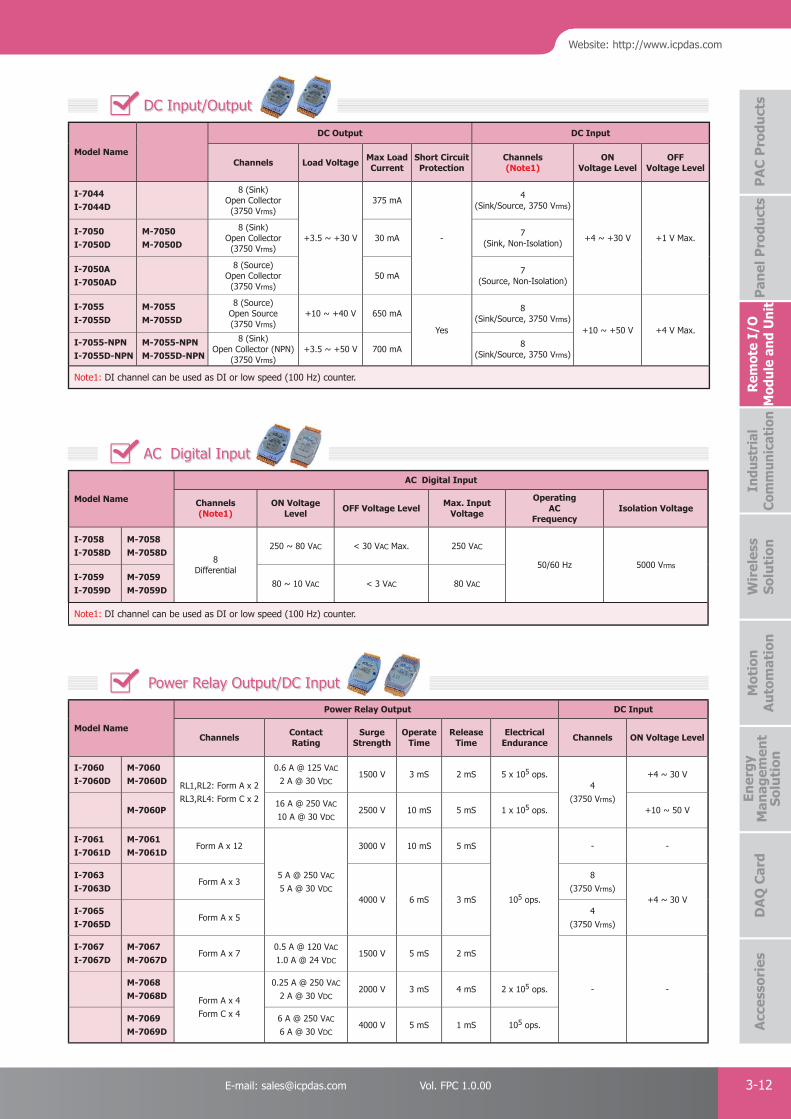
PAC Products
3-12E-mail: [email protected] Vol. FPC 1.0.00
Website: http://www.icpdas.com
PA
C P
rodu
cts
Pan
el P
rodu
cts
Rem
ote
I/O
M
odul
e an
d U
nit
DA
Q C
ard
Indu
stri
al
Com
mun
icat
ion
Wir
eles
s So
luti
onM
otio
n
Au
tom
atio
nA
cces
sori
esEn
ergy
M
anag
emen
tSo
luti
on
Model Name
AC Digital Input
Channels(Note1)
ON Voltage Level OFF Voltage Level Max. Input
Voltage
Operating AC
FrequencyIsolation Voltage
I-7058I-7058D
M-7058M-7058D
8Differential
250 ~ 80 VAC < 30 VAC Max. 250 VAC
50/60 Hz 5000 Vrms
I-7059I-7059D
M-7059M-7059D
80 ~ 10 VAC < 3 VAC 80 VAC
Note1: DI channel can be used as DI or low speed (100 Hz) counter.
Model Name
DC Output DC Input
Channels Load Voltage Max Load Current
Short Circuit Protection
Channels (Note1)
ON Voltage Level
OFF Voltage Level
I-7044I-7044D
8 (Sink)Open Collector (3750 Vrms)
+3.5 ~ +30 V
375 mA
-
4 (Sink/Source, 3750 Vrms)
+4 ~ +30 V +1 V Max.I-7050I-7050D
M-7050M-7050D
8 (Sink)Open Collector (3750 Vrms)
30 mA 7 (Sink, Non-Isolation)
I-7050AI-7050AD
8 (Source)Open Collector (3750 Vrms)
50 mA 7 (Source, Non-Isolation)
I-7055I-7055D
M-7055M-7055D
8 (Source)Open Source (3750 Vrms)
+10 ~ +40 V 650 mA
Yes
8 (Sink/Source, 3750 Vrms)
+10 ~ +50 V +4 V Max.I-7055-NPNI-7055D-NPN
M-7055-NPNM-7055D-NPN
8 (Sink)Open Collector (NPN)
(3750 Vrms)+3.5 ~ +50 V 700 mA 8
(Sink/Source, 3750 Vrms)
Note1: DI channel can be used as DI or low speed (100 Hz) counter.
AC Digital Input
DC Input/Output
Model Name
Power Relay Output DC Input
Channels Contact Rating
Surge Strength
Operate Time
Release Time
ElectricalEndurance Channels ON Voltage Level
I-7060I-7060D
M-7060M-7060D RL1,RL2: Form A x 2
RL3,RL4: Form C x 2
0.6 A @ 125 VAC
2 A @ 30 VDC1500 V 3 mS 2 mS 5 x 10⁵ ops.
4 (3750 Vrms)
+4 ~ 30 V
M-7060P16 A @ 250 VAC
10 A @ 30 VDC2500 V 10 mS 5 mS 1 x 10⁵ ops. +10 ~ 50 V
I-7061I-7061D
M-7061M-7061D
Form A x 12
5 A @ 250 VAC
5 A @ 30 VDC
3000 V 10 mS 5 mS
105 ops.
- -
I-7063I-7063D
Form A x 3
4000 V 6 mS 3 mS
8(3750 Vrms)
+4 ~ 30 VI-7065I-7065D
Form A x 54
(3750 Vrms)
I-7067I-7067D
M-7067M-7067D
Form A x 70.5 A @ 120 VAC
1.0 A @ 24 VDC1500 V 5 mS 2 mS
- -M-7068M-7068D Form A x 4
Form C x 4
0.25 A @ 250 VAC
2 A @ 30 VDC2000 V 3 mS 4 mS 2 x 10⁵ ops.
M-7069M-7069D
6 A @ 250 VAC
6 A @ 30 VDC4000 V 5 mS 1 mS 105 ops.
Power Relay Output/DC Input
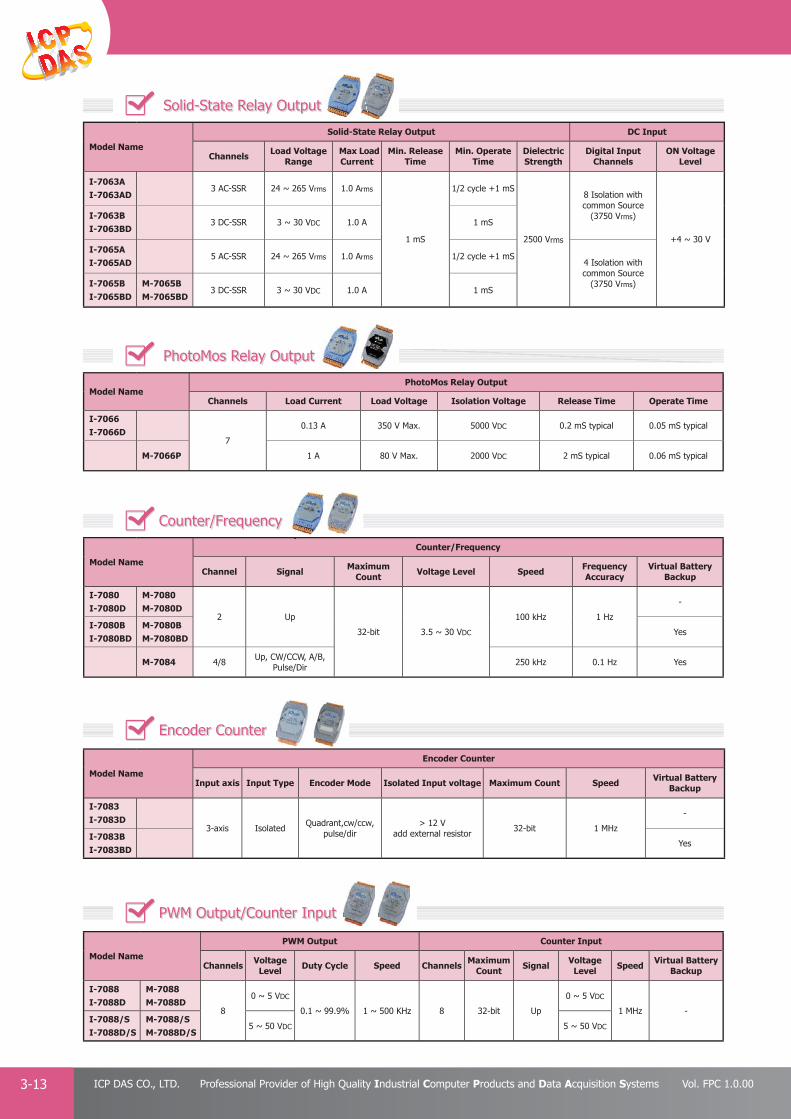
PAC Products
3-13 ICP DAS CO., LTD. Professional Provider of High Quality Industrial Computer Products and Data Acquisition Systems Vol. FPC 1.0.00
Model Name
Solid-State Relay Output DC Input
Channels Load Voltage Range
Max Load Current
Min. Release Time
Min. Operate Time
Dielectric Strength
Digital InputChannels
ON Voltage Level
I-7063AI-7063AD
3 AC-SSR 24 ~ 265 Vrms 1.0 Arms
1 mS
1/2 cycle +1 mS
2500 Vrms
8 Isolation with common Source
(3750 Vrms)
+4 ~ 30 V
I-7063BI-7063BD
3 DC-SSR 3 ~ 30 VDC 1.0 A 1 mS
I-7065AI-7065AD
5 AC-SSR 24 ~ 265 Vrms 1.0 Arms 1/2 cycle +1 mS4 Isolation with common Source
(3750 Vrms)I-7065BI-7065BD
M-7065BM-7065BD
3 DC-SSR 3 ~ 30 VDC 1.0 A 1 mS
Model Name PhotoMos Relay Output
Channels Load Current Load Voltage Isolation Voltage Release Time Operate Time
I-7066I-7066D
7
0.13 A 350 V Max. 5000 VDC 0.2 mS typical 0.05 mS typical
M-7066P 1 A 80 V Max. 2000 VDC 2 mS typical 0.06 mS typical
Solid-State Relay Output
PhotoMos Relay Output
Model Name
Counter/Frequency
Channel Signal Maximum Count Voltage Level Speed Frequency
AccuracyVirtual Battery
Backup
I-7080I-7080D
M-7080M-7080D
2 Up
32-bit 3.5 ~ 30 VDC
100 kHz 1 Hz
-
I-7080BI-7080BD
M-7080BM-7080BD
Yes
M-7084 4/8 Up, CW/CCW, A/B, Pulse/Dir 250 kHz 0.1 Hz Yes
Model Name
Encoder Counter
Input axis Input Type Encoder Mode Isolated Input voltage Maximum Count Speed Virtual BatteryBackup
I-7083I-7083D
3-axis Isolated Quadrant,cw/ccw,pulse/dir
> 12 V add external resistor 32-bit 1 MHz
-
I-7083BI-7083BD
Yes
Counter/Frequency
Encoder Counter
PWM Output/Counter Input
Model Name
PWM Output Counter Input
Channels Voltage Level Duty Cycle Speed Channels Maximum
Count Signal Voltage Level Speed Virtual Battery
Backup
I-7088I-7088D
M-7088M-7088D
8
0 ~ 5 VDC
0.1 ~ 99.9% 1 ~ 500 KHz 8 32-bit Up
0 ~ 5 VDC
1 MHz -I-7088/SI-7088D/S
M-7088/SM-7088D/S
5 ~ 50 VDC 5 ~ 50 VDC
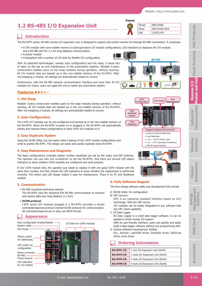
PAC Products
3-14E-mail: [email protected] Vol. FPC 1.0.00
Website: http://www.icpdas.com
PA
C P
rodu
cts
Pan
el P
rodu
cts
Rem
ote
I/O
M
odul
e an
d U
nit
DA
Q C
ard
Indu
stri
al
Com
mun
icat
ion
Wir
eles
s So
luti
onM
otio
n
Au
tom
atio
nA
cces
sori
esEn
ergy
M
anag
emen
tSo
luti
on
Hot SwapAuto
Confi guration
Easy Duplicate System
Easy Maintenance
Easy Diagnosis
Rugged Industrial Environment
• Power On Value & Safe Value
• Dual Watchdog
• +10 ~ +30 VDC Power Input
• -25 ~ +75°C Operating Temperature
• ESD & Surge Protection
Taiwan 096134568
China 200710181138.6
USA 11/979,474
Patent
1.2 RS-485 I/O Expansion Unit
The RU-87Pn series, RS-485 remote I/O expansion unit, is designed to acquire and control remote I/O through RS-485 connections. It comprises
• A CPU module with none-volatile memory to backup/restore I/O module confi gurations; LED indicators to diagnose the I/O module; and a RS-485 port for 1.2 Km long distance communication.
• A power module• A backplane with a number of I/O slots for fl exible I/O confi guration.
With its patented technologies, namely auto configuration and hot swap, it saves lots of labor on the set up and maintenance of the automation systems. Reliable 3-piece construction enables users to hot swap modules during operation, without rewiring. All I/O module data are backed up in the non-volatile memory of the RU-87Pn. After hot-swapping a module, all settings are automatically loaded to recover.
Furthermore, with the RS-485 network communication interface and more than 30 I/O modules for choice, users can apply the unit to nearly any automation system.
5. Communication • RS-485 industrial multi-drop network
The RU-87Pn uses the industrial EIA RS-485 communication to transmit and receive data over long distance (1.2 Km).
• DCON protocolI-87K series I/O modules plugged in a RU-87Pn provides a simple command/response protocol (named DCON protocol) for communication. All command/response are in easy use ASCII format.
1. Hot Swap Reliable 3-piece construction enables users to hot swap modules during operation, without rewiring. All I/O module data are backed up in the non-volatile memory of the RU-87Pn. After hot-swapping a module, all settings are automatically loaded to recover.
2. Auto Confi guration The I-87K I/O modules can be pre-confi gured and backed up in the non-volatile memory of the RU-87Pn. When the RU-87Pn is power on or plugged in, the RU-87Pn will automatically checks and restores these confi gurations to each I-87K I/O modules on it. 3. Easy Duplicate System Using the DCON Utility, you can easily make a backup of the I-87K module confi gurations and write to another RU-87Pn. This design can easily and quickly duplicate many RU-87Pn.
4. Easy Maintenance and DiagnosisThe basic confi gurations (includes station number, baudrate) are set by the rotary and DIP switches. The operator can use only one screwdriver to set the RU-87Pn. And there are several LED status indicators to show whether I-87K modules are confi gured and work properly.
If one I-87K module fails, the operator just needs to replace it with one good I-87K module with the same item number. And then checks the LED indicators to know whether the replacement is performed correctly. The switch and LED design makes it easy for maintenance. There is no PC and Notebook needed.
es lots -piece
wiring. After
0 I/O
6. Fully Software SupportThe free charge software utility and development kits include
A: DCON Utility: for configurationB: OPC Servers:
OPC is an industrial standard interface based on OLE technology. With the OPC server, I/O modules can be easily integrated to any software that has OPC client capability.
C. EZ Data Logger EZ Data Logger is a small data logger software. It can be applied to small remote I/O system. With its user-friendly interface, users can quickly and easily build a data logger software without any programming skill.
D. Various Software Development Toolkits DLL, ActiveX, LabVIEW driver, InduSoft driver, DASYLab driver, Linux driver
I/O Slots for I-87K modules
RU-87P1 CR 1 slot I/O Expansion Unit (RoHS)
RU-87P2 CR 2 slots I/O Expansion Unit (RoHS)
RU-87P4 CR 4 slots I/O Expansion Unit (RoHS)
RU-87P8 CR 8 slots I/O Expansion Unit (RoHS)
CPU PowerSystem readyAuto Confi guration Enable/Disable
Frame GroundRS-485
Rotary switchfor addressing
Power connector
DIP switch for confi guration
LED indicators for I/O healthy
Introduction
Ordering Information
Appearance
Features

PAC Products
3-15 ICP DAS CO., LTD. Professional Provider of High Quality Industrial Computer Products and Data Acquisition Systems Vol. FPC 1.0.00
1.3 tM Series Modules
The tM series is a family of network data acquisition and control modules with digital or analog I/O functions. The modules can be remotely controlled through an RS-485 serial bus by using DCON and Modbus RTU/ASCII protocols. The selectable transmission speed of the RS-485 port is up to 115,200 bps. Modbus has become a de facto standard communications protocol in industry, and is now the most commonly available means of connecting industrial electronic devices. This makes the tM series perfect integration with the HMI, SCADA, PLC and other software systems.
The tM series tiny RS-485 I/O modules support various I/O types, like photo-isolated digital input, power relay, photoMOS relay, open collector output, and analog input (voltage and current). Compared with the M-7000 series, the tM series is more cost-effective with low channel count design that is suitable for distributed I/O points applications.
The tM series provides dual watchdog: module watchdog and host watchdog. The module watchdog is designed to automatically reset the microprocessor when the module hangs. The host watchdog monitors the host controller (PC or PLC), and the output of the module can go to predefi ned safe value state when the host fails.
For maximum space savings, the tM series is offered in an amazing tiny form-factor that makes it can be easily installed in anywhere, even directly embedded into a machine. It is equipped with two removable terminal block connectors for easy wiring.
Features
Rear ViewLeft Side View Front View
52
77.498
6.6
19
35.4
23
10.2
27
tM Series Models
Model Name Bus Protocols AI AO DI DO
tM-AD5
RS-485Modbus RTU
Modbus ASCIIDCON
5-ch (Differential, Voltage) - - -
tM-AD5C 5-ch (Differential, Current) - - -
tM-AD8 8-ch (Single-Ended, Voltage) - - -
tM-AD8C 8-ch (Single-Ended, Current) - - -
tM-AD4P2C22-ch (Single-Ended, Voltage)2-ch (Single-Ended, Current)
- 2-ch (Source) 2-ch (NPN, Sink)
tM-DA1P1R1 - 1-ch (Single-Ended, Voltage) 1-ch (Sink/Source) 1-ch Form A Relay
tM-TH8 8-ch (Thermistor) - - -
tM-P8 - - 8-ch (Sink/Source) -
tM-C8 - - - 8-ch (NPN, Sink)
tM-P4C4 - - 4-ch (Source) 4-ch (NPN, Sink)
tM-P4A4 - - 4-ch (Sink) 4-ch (PNP, Source)
tM-P3R3 - - 3-ch (Sink/Source) 3-ch Form A Relay
tM-R5 - - - 5-ch Form A Relay
RS-485 Industrial Multi-Drop Network
Programmable I/O Type and Range
Easy Mounting and Connection
Rugged Industrial Environment
Dual Watchdog Design
DI Latch Function
Low Speed Counter
Programmable Power-on Value and Safe Value
Versatile Communication Protocols: DCON,
Modbus RTU and Modbus ASCII
Expandable Network
Tiny Form Factor
Introduction
Dimensions (Units: mm)
Selection Guide
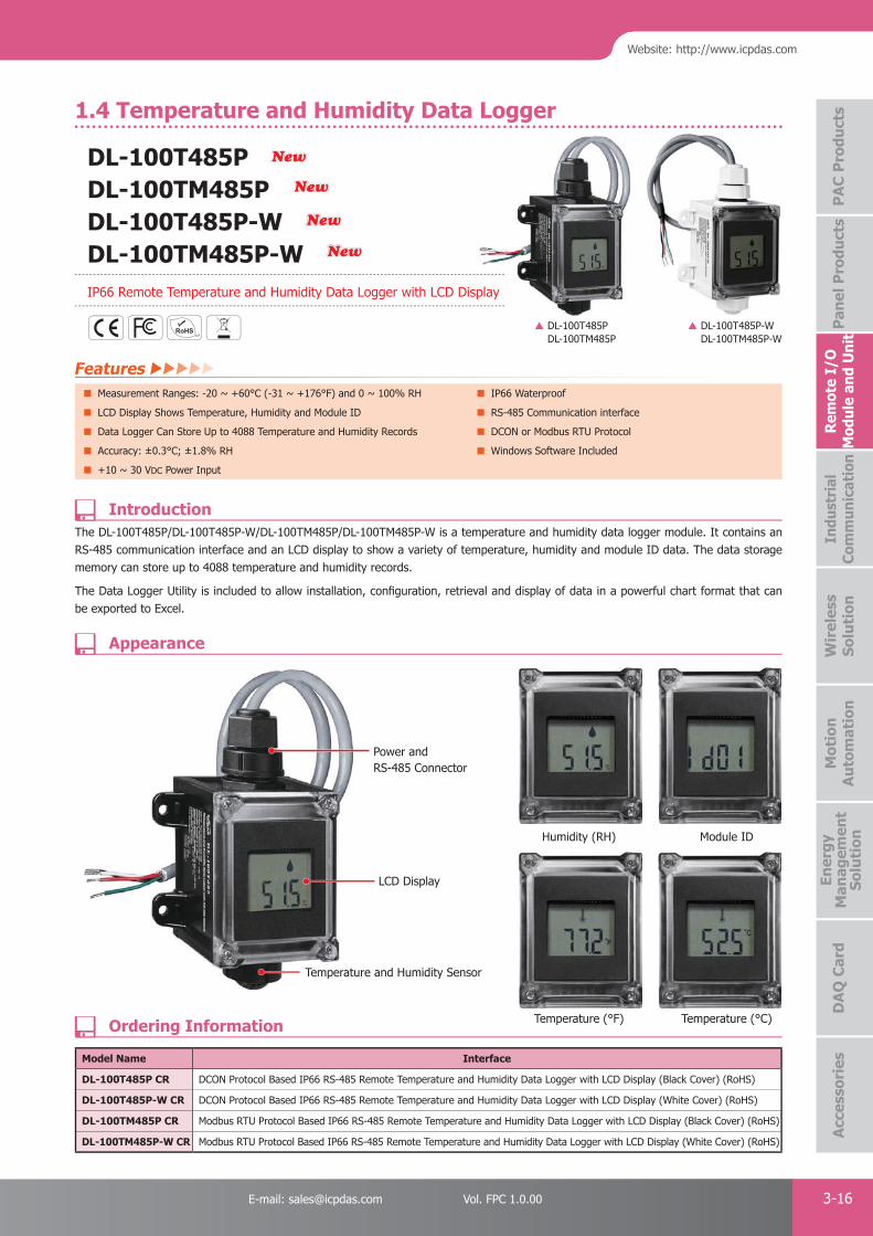
PAC Products
3-16E-mail: [email protected] Vol. FPC 1.0.00
Website: http://www.icpdas.com
PA
C P
rodu
cts
Pan
el P
rodu
cts
Rem
ote
I/O
M
odul
e an
d U
nit
DA
Q C
ard
Indu
stri
al
Com
mun
icat
ion
Wir
eles
s So
luti
onM
otio
n
Au
tom
atio
nA
cces
sori
esEn
ergy
M
anag
emen
tSo
luti
on
The DL-100T485P/DL-100T485P-W/DL-100TM485P/DL-100TM485P-W is a temperature and humidity data logger module. It contains an RS-485 communication interface and an LCD display to show a variety of temperature, humidity and module ID data. The data storage memory can store up to 4088 temperature and humidity records.
The Data Logger Utility is included to allow installation, confi guration, retrieval and display of data in a powerful chart format that can be exported to Excel.
DL-100T485PDL-100TM485P
DL-100T485P-WDL-100TM485P-W
Power and RS-485 Connector
LCD Display
Temperature and Humidity Sensor
Humidity (RH)
Temperature (°C)
Module ID
Temperature (°F)
Temperat
Model Name Interface
DL-100T485P CR DCON Protocol Based IP66 RS-485 Remote Temperature and Humidity Data Logger with LCD Display (Black Cover) (RoHS)
DL-100T485P-W CR DCON Protocol Based IP66 RS-485 Remote Temperature and Humidity Data Logger with LCD Display (White Cover) (RoHS)
DL-100TM485P CR Modbus RTU Protocol Based IP66 RS-485 Remote Temperature and Humidity Data Logger with LCD Display (Black Cover) (RoHS)
DL-100TM485P-W CR Modbus RTU Protocol Based IP66 RS-485 Remote Temperature and Humidity Data Logger with LCD Display (White Cover) (RoHS)
Features Measurement Ranges: -20 ~ +60°C (-31 ~ +176°F) and 0 ~ 100% RH IP66 Waterproof
LCD Display Shows Temperature, Humidity and Module ID RS-485 Communication interface
Data Logger Can Store Up to 4088 Temperature and Humidity Records DCON or Modbus RTU Protocol
Accuracy: ±0.3°C; ±1.8% RH Windows Software Included
+10 ~ 30 VDC Power Input
Introduction
Appearance
Ordering Information
DL-100T485PDL-100TM485P DL-100T485P-WDL-100TM485P-WIP66 Remote Temperature and Humidity Data Logger with LCD Display
NewNew
NewNew
NewNew
NewNew
1.4 Temperature and Humidity Data Logger

PAC Products
3-17 ICP DAS CO., LTD. Professional Provider of High Quality Industrial Computer Products and Data Acquisition Systems Vol. FPC 1.0.00
The DL-300 series is a high-performance, LCD display data logger for monitoring indoor air quality, comprising carbon monoxide, carbon dioxide, temperature, humidity and dew point temperature. It comes with not only an easy-to-use touch menu interface for local confi guration and operation, but also a web-based confi guration interface that you can access in your web browser.
The DL-300 series can store up to 450,000 downloadable records with data and time stamps. Free Windows software and Android App can be used to access the real-time data from a DL-300 logger anytime and anywhere as long as they are on the same local network as the logger. With support for popular industrial protocols such as DCON/Modbus RTU/Modbus TCP and widely used communication interfaces including RS-485, Ethernet and PoE, the DL-300 logger is easy to be integrated into existing HMI or SCADA systems and easy to be maintained in a distributed control system.
Features Simultaneous Display for CO, CO2, Temperature, Humidity and Dew Point Measurement Range
Non-dispersive infrared (NDIR) CO2 sensor CO: 0 ~ 1000 ppm
Up to 450,000 records with data and time stamps CO2 0 ~ 9999 ppm
Support DCON, Modbus RTU, Modbus TCP Protocols Web-based Confi guration Interface
Providing RS-485/Ethernet/PoE Communication Interfaces Free Software Utility and Android APP
Relay Output for CO/CO2 Alarm Output
Introduction
DL-301DL-302DL-303Remote CO/CO2/Temperature/Humidity and /
Dew Point Data Logger with LCD Display
NewNew
NewNew
NewNew
Free and Power DL300 Utility Software
The DL300 Utility is designed for setup modules, monitor real-time data, group DL-300 modules to view and manage the statuses of distribution groups, download log data and export data into a .CSV file that can be imported into any industry-standard software or spreadsheet for analysis.
2.8" Big Size LCD and Clear Color Chart for Representing the CO/CO2 Level
Multi-Platform Remote Access SoftwareAndroid App, DL300 Utility and regular web browser can be used to access the real-time data from a DL-300 logger anytime and anywhere as long as they are on the same local network as the logger.

PAC Products
3-18E-mail: [email protected] Vol. FPC 1.0.00
Website: http://www.icpdas.com
PA
C P
rodu
cts
Pan
el P
rodu
cts
Rem
ote
I/O
M
odul
e an
d U
nit
DA
Q C
ard
Indu
stri
al
Com
mun
icat
ion
Wir
eles
s So
luti
onM
otio
n
Au
tom
atio
nA
cces
sori
esEn
ergy
M
anag
emen
tSo
luti
on
Transportation of Food or PharmaceuticalsFood and Beverage Industry (HACCP)Blood Stations and Pharmacies
Building and Energy ManagementWarehouse ManagementMuseums, Archives and Galleries
System Specifi cations
Dimensions (Units: mm)
Application
Appearance
Model Name DL-301 DL-302 DL-303
Measurement
CO Range 0 to 1000 ppm - 0 to 1000 ppm
CO2 Range - 0 to 9999 ppm
Temperature Range -10 to +50°C
Relative Humidity Range 0 to 100 RH
Dew Point Calculated with temperature and relative humidity
Data Logger Yes, up to 450,000 records with data and time stamps
Alarm CO Upper Limit Alarm CO2 Upper Limit Alarm CO/CO2 Upper Limit Alarm
Communication
Communication Interface PoE, Ethernet, RS-485
Communication Protocol Modbus/TCP, Modbus/RTU, DCON
Electrical
Power Input +12 to +48 VDC or PoE (IEEE 802.3af, Class 1 (48 V))
Power Consumption 1.84 W (Max.) 2.65 W (Max.) 2.83 W (Max.)
Mechanical
Dimension (W x H x D) 114 mm x 106 mm x 56 mm
Installation Desktop, DIN-Rail or Wall Mounting
Environment
Operating Temperature 0 ~ +50°C
Storage Temperature -30 ~ +75°C
Operating Humidity 10 ~ 90% RH, non-condensing
Left View Front View Rear View
114
10656
24.2
35.6
53.3
2.8” LCD Touch Screen
Power/ Ethernet Link/ Alarm LED Indicators
Connector for Power/ Frame Ground / RS-485/ Alarm Relay Output
PoE/ non-PoE Ethernet port
DIN-Rail Mounting
USB (For Updating Firmware Only)
DIP Switch
Holes for Wall-mountingBuzzer

PAC Products
3-19 ICP DAS CO., LTD. Professional Provider of High Quality Industrial Computer Products and Data Acquisition Systems Vol. FPC 1.0.00
The PIR-130 module includes a 1-channel passive infrared (PIR) sensor that is able to detect infrared waves generated by human within a range of approximately 8 meters in diameter with a 360° coverage area. The PIR-130 is used for indoor motion detection, and can be confi gured to automatically switch on a light if motion is detected.The PIR-130 module also includes a 1-channel temperature sensor that can be used for measuring room temperature or can be confi gured to activate a fi re alarm.
Features 360° Motion Detection Up to 8 m Diameter Range
Time-Delay / Lux. / Sensitivity Adjustable
Photo Sensor Inside for Smart Switch-on Control Ceiling Surface Mount Design
LED Indicator for PIR/Temperature Sensor The Temperature Sensor for Measuring Room Temperature or Fire Alarm
RS-485 Communication Interface Relay Output Can be Used to Control the Light Via the PIR/Temperature Sensor
DCON and Modbus RTU Protocols Up to 1500 W Incandescent and 300 W Fluorescent (T8) Loading Capability
Introduction
Specifi cations
Ordering Information
PIR-130-AC/PIR-130-DC
1.5 PIR Motion Sensor and Temperature Sensor Module
Model Name PIR-130-AC PIR-130-DC
PIR
Time-delay Hardware: 8-step Switch-selectable (seconds): 6, 16, 33, 66, 131, 262, 524, 1049Software: 16-step (seconds): 2, 4, 6, 8, 16, 33, 49, 66, 131, 262, 393, 524, 1049, 2097, 3146, 4194
LUX Control Level Hardware: 2 mode (Dawn and dust) / Software: 5-step
Detection Range Distance: 4 meters Max.
Detection Field of View 360º; Diameter 8 meters Max.
Temperature Sensor
Measurement Range -25 ~ +100°C
Fire Alarm 65°C (Programmable)
Resolution 0.0625°C
Accuracy ±2°C
Relay Output
Channels 1
Type Power Relay, Form C
Max. Load Current NO: 10 A @ 250 VACNC: 6 A @ 250 VAC
Load Wattage Incandescent Bulb: 1500 W Max.; Fluorescent Lamp 300 W Max.
RS-485 Interface
Transmission Distance (m) Dependent on Baud Rate. For example, 1200 m Max. at 9600 bps.
Baud Rate (bps) 1200, 2400, 4800, 9600, 19200, 38400, 57600, 115200
Protocol DCON, Modbus RTU
Node Address Hardware: 160 ~ 191 / Software: 1 ~ 255
LED Indicators
LED Indicators Yes,1 as Power/Communication Indicator. 1 as Alarm Indicator.
EMS Protection
ESD (IEC 61000-4-2) ±4 kV Contact for each Terminal, ±8 kV Air for Random Point
EFT (IEC 61000-4-4) ±4 kV for Power Line
Power Requirements
Power supply 110 ~ 220 VAC 10 ~ 30 VDC
Power Consumption 2 W 1.3 W
Mechanical
Installation Ceiling mounting
Dimensions (D x H) Ø 121 mm x 52 mm
Environment
Operating Temperature -25 ~ +75°C
Storage Temperature -30 ~ +80°C
Humidity 10 to 90% RH, Non-condensing
PIR-130-AC CR PIR Motion Sensor and Temperature Sensor Module (110~220 VAC)(RoHS)
PIR-130-DC CR PIR Motion Sensor and Temperature Sensor Module (10~30 VDC)(RoHS)
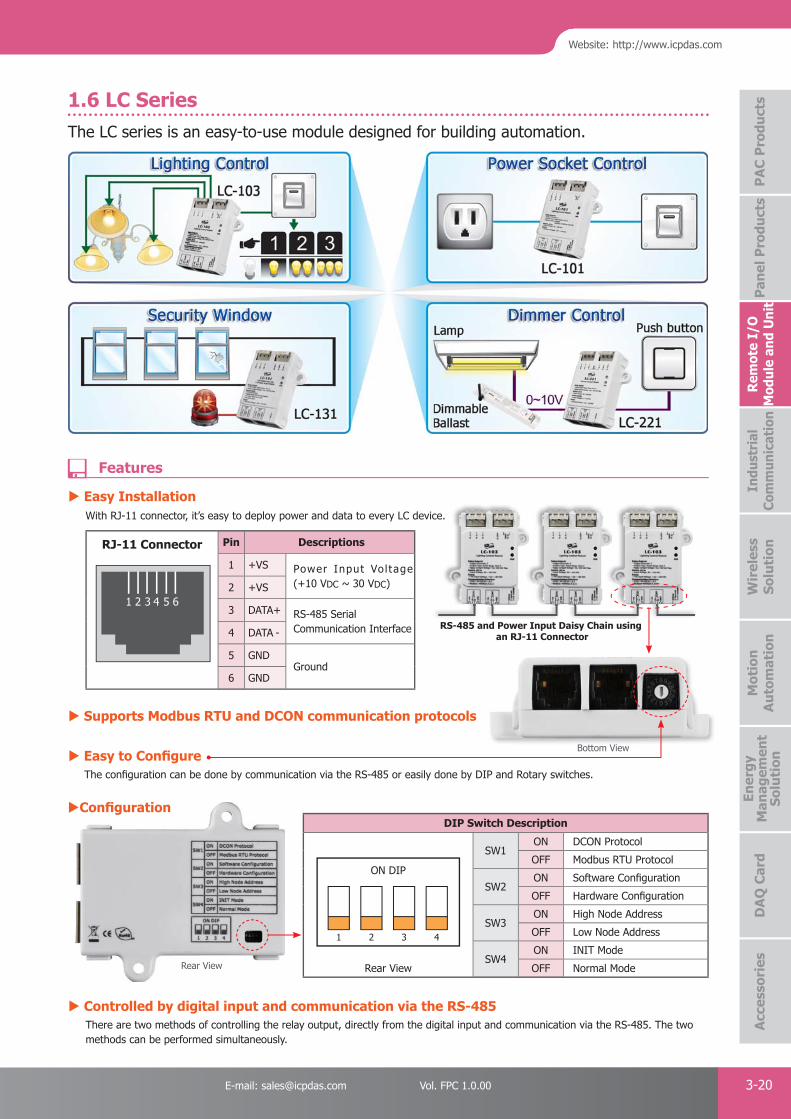
PAC Products
3-20E-mail: [email protected] Vol. FPC 1.0.00
Website: http://www.icpdas.com
PA
C P
rodu
cts
Pan
el P
rodu
cts
Rem
ote
I/O
M
odul
e an
d U
nit
DA
Q C
ard
Indu
stri
al
Com
mun
icat
ion
Wir
eles
s So
luti
onM
otio
n
Au
tom
atio
nA
cces
sori
esEn
ergy
M
anag
emen
tSo
luti
on
1.6 LC SeriesThe LC series is an easy-to-use module designed for building automation.
RJ-11 Connector Pin Descriptions
1 +VS Power Input Vo l tage (+10 VDC ~ 30 VDC)2 +VS
3 DATA+ RS-485 Serial Communication Interface4 DATA -
5 GNDGround
6 GND
1 2 43 5 6
RS-485 and Power Input Daisy Chain using an RJ-11 Connector
Easy Installation With RJ-11 connector, it’s easy to deploy power and data to every LC device.
Supports Modbus RTU and DCON communication protocols
Easy to Confi gure The confi guration can be done by communication via the RS-485 or easily done by DIP and Rotary switches.
Controlled by digital input and communication via the RS-485 There are two methods of controlling the relay output, directly from the digital input and communication via the RS-485. The two
methods can be performed simultaneously.
ON DIP
1 2 3 4
DIP Switch Description
Rear View
SW1ON DCON Protocol
OFF Modbus RTU Protocol
SW2ON Software Confi guration
OFF Hardware Confi guration
SW3ON High Node Address
OFF Low Node Address
SW4ON INIT Mode
OFF Normal Mode
Confi guration
Bottom View
Rear View
Features
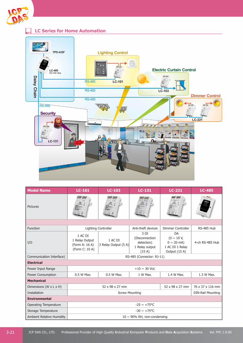
PAC Products
3-21 ICP DAS CO., LTD. Professional Provider of High Quality Industrial Computer Products and Data Acquisition Systems Vol. FPC 1.0.00
Model Name LC-101 LC-103 LC-131 LC-221 LC-485
Pictures
Function Lighting Controller Anti-theft devices Dimmer Controller RS-485 Hub
I/O
1 AC DI1 Relay Output (Form A: 16 A) (Form C: 10 A)
1 AC DI3 Relay Output (5 A)
3 DI(Disconnection
detection)1 Relay output
(15 A)
DA(0 ~ 10 V,
0 ~ 20 mA)1 AC DI 1 RelayOutput (15 A)
4-ch RS-485 Hub
Communication Interface) RS-485 (Connector: RJ-11)
Electrical
Power Input Range +10 ~ 30 VDC
Power Consumption 0.5 W Max. 0.5 W Max. 1 W Max. 1.4 W Max. 1.3 W Max.
Mechanical
Dimensions (W x L x H) 52 x 98 x 27 mm 52 x 98 x 27 mm 76 x 37 x 116 mm
Installation Screw Mounting DIN-Rail Mounting
Environmental
Operating Temperature -25 ~ +75°C
Storage Temperature -30 ~ +75°C
Ambient Relative Humidity 10 ~ 90% RH, non-condensing
LC Series for Home Automation
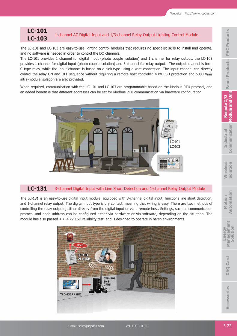
PAC Products
3-22E-mail: [email protected] Vol. FPC 1.0.00
Website: http://www.icpdas.com
PA
C P
rodu
cts
Pan
el P
rodu
cts
Rem
ote
I/O
M
odul
e an
d U
nit
DA
Q C
ard
Indu
stri
al
Com
mun
icat
ion
Wir
eles
s So
luti
onM
otio
n
Au
tom
atio
nA
cces
sori
esEn
ergy
M
anag
emen
tSo
luti
on
The LC-131 is an easy-to-use digital input module, equipped with 3-channel digital input, functions line short detection, and 1-channel relay output. The digital input type is dry contact, meaning that wiring is easy. There are two methods of controlling the relay outputs, either directly from the digital input or via a remote host. Settings, such as communication protocol and node address can be configured either via hardware or via software, depending on the situation. The module has also passed + / -4 kV ESD reliability test, and is designed to operate in harsh environments.
The LC-101 and LC-103 are easy-to-use lighting control modules that requires no specialist skills to install and operate, and no software is needed in order to control the DO channels.The LC-101 provides 1 channel for digital input (photo couple isolation) and 1 channel for relay output, the LC-103 provides 1 channel for digital input (photo couple isolation) and 3 channel for relay output. The output channel is form C type relay, while the input channel is based on a sink-type using a wire connection. The input channel can directly control the relay ON and OFF sequence without requiring a remote host controller. 4 kV ESD protection and 5000 Vrms intra-module isolation are also provided.
When required, communication with the LC-101 and LC-103 are programmable based on the Modbus RTU protocol, and an added benefi t is that different addresses can be set for Modbus RTU communication via hardware confi guration
LC-131 3-channel Digital Input with Line Short Detection and 1-channel Relay Output Module
LC-101 1-channel AC Digital Input and 1/3-channel Relay Output Lighting Control Module
LC-103

PAC Products
3-23 ICP DAS CO., LTD. Professional Provider of High Quality Industrial Computer Products and Data Acquisition Systems Vol. FPC 1.0.00
RS-485 Active HubThe LC-485 is 4-ch RS-485 active star wiring hub, it has 4 independent RS-485 output channels and one RS-485 input channel. Each output channel is equipped with an individual driver. The data from a master to the input channel will simultaneously be forwarded to all the four output channels.
RS-485 Short-Circuit protectionThe Short-circuit protection can automatically shut off the breakdown channel, this kind of design can suffi ce to protect the communication system. When connected RS-485 equipment breaks down, the breakdown channel will be isolated to ensure that other equipment work normally.
The LC-221 is an easy-to-use dimming ballast control module that requires no specialist skills to install and operate. It provides two methods of controlling the brightness of fl uorescent lamps via a dimmer, either via digital input or a host controller. The digital input can directly control the light value from 10% to 100% luminous fl ux in sequence, without requiring a remote host controller. 4 kV ESD protection and 2500 VDC intra-module isolation are also provided. When required, communication with the LC-221 is programmable based on the Modbus RTU protocol, and an added benefi t is that different addresses can be set for Modbus RTU communication via hardware confi guration.
LC-485 4 Channels RS-485 Active Hub
LC-221 4 Channels RS-485 Active Hub
PAC Products
3-24E-mail: [email protected] Vol. FPC 1.0.00
Website: http://www.icpdas.com
PA
C P
rodu
cts
Pan
el P
rodu
cts
Rem
ote
I/O
M
odul
e an
d U
nit
DA
Q C
ard
Indu
stri
al
Com
mun
icat
ion
Wir
eles
s So
luti
onM
otio
n
Au
tom
atio
nA
cces
sori
esEn
ergy
M
anag
emen
tSo
luti
on
2. Ethernet I/O Products
Model Name tET/tPET SeriesET-7000
PET-7000ET-7200
PET-7200
Pictures
Communication
Ethernet 10/100 M, RJ-45 x 1 10/100 M, RJ-45 x 2
Protocol Modbus TCP, Modbus UDP
Security Web Password and IP Filter ID, Password and IP Filter
Max. Sockets 5 12
Web Server Yes Yes
User-defi ned Web pages
- Yes (Web HMI)
I/O
I/O pins 10 pins 21 pins 22 pins
DI Counter 32-bit, 3.5 kHz 32-bit, 500 Hz 32-bit, 100 Hz
DIO LED Indicators - - Yes
Pair Connection Yes (Polling/Push Mode) Yes (Polling Mode)
Mechanical
Reset Button - - Yes
Power Input Pins 1 pair 1 pair 2 pair
Dimensions (W x L x D) 52 mm x 98 mm x 27 mm 72 mm x 123 mm x 35 mm 76 mm x 120 mm x 38 mm
Although the RS-485 remote I/O module is still selling well, we found more and more demand of Ethernet based remote I/O modules. Our Ethernet remote I/O modules support Modbus TCP, Modbus UDP protocol. We also provide web HMI, Web server, OPC server, security mechanism..etc. According to different application, we have developed various Ethernet I/O units and modules, such as compact size ET-87Pn-MTCP, palm-size ET-7000/PET-7000/ET-7200/PET-7200 series and tiny-size tET/tPET series. The module has diversifi ed I/O interface, such as overvoltage-protection analog input, relay output, digital input/output, counter, timer.
The brief comparison is as the following table. Besides those regular Ethernet I/O modules, we will release EtherCAT, Ethernet/IP and PROFINET I/O modules.
Further more, we also developed ET-87Pn-MTCP, a series of Ethernet remote I/O unit for compact and modular I/O expansion. It comprises a CPU, a power module and a backplane with a number of I/O slots for fl exible I/O confi guration.

PAC Products
3-25 ICP DAS CO., LTD. Professional Provider of High Quality Industrial Computer Products and Data Acquisition Systems Vol. FPC 1.0.00
The ET-7000/ET-7200, a web-based Ethernet I/O module, features a built-in web server which allows confi guration, I/O monitoring and I/O control by simply using a regular web browser. Remote control is as easy as surfi ng the Internet.
Besides Web HMI function, no more programming or HTML skills are required; creating dynamic and attractive web pages for I/O monitoring and I/O control would be fun to engineers ever after. The ET-7000/ET-7200 offers easy and safe access for users from anytime and anywhere! In addition, the ET-7000/ET-7200 also supports Modbus TCP protocol that makes perfect integration to SCADA software.
Furthermore, PET-7000/PET-7200 features “PoE” that not only Ethernet but also power is carried through an Ethernet cable. This feature makes installation of PET-7000/PET-7200 a piece of cake. Imagine that no more unnecessary wires, only an Ethernet cable takes care of everything in the fi eld.
2. Daisy-Chain Ethernet CablingThe ET-7200/PET-7200 Series has a built-in two-port Ethernet switch to implement daisy-chain topology. The cabling is much easier and total costs of cable and switch are signifi cantly reduced.
1. Power over Ethernet (PoE)The PET-7000/PET-7200 series module can be powered by an IEEE802.3af compliant PoE switch. Both Ethernet and power can be carried by an Ethernet cable eliminating the need for additional wiring and power supply.
3. LAN BypassLAN Bypass feature guarantees the Ethernet communication. It will automatically active to continue the network traffic when the ET-7200/PET-7200 looses its power.
4. Communication SecurityAccount and password are needed when logging into the web server. An IP address fi lter is also included, which can be used to allow or deny connections with specifi c IP addresses.
2.1 Ethernet Modbus TCP I/O Modules
Introduction
Features

PAC Products
3-26E-mail: [email protected] Vol. FPC 1.0.00
Website: http://www.icpdas.com
PA
C P
rodu
cts
Pan
el P
rodu
cts
Rem
ote
I/O
M
odul
e an
d U
nit
DA
Q C
ard
Indu
stri
al
Com
mun
icat
ion
Wir
eles
s So
luti
onM
otio
n
Au
tom
atio
nA
cces
sori
esEn
ergy
M
anag
emen
tSo
luti
on
5. Support for both Modbus TCP and Modbus UDP ProtocolsThe Modbus TCP, Modbus UDP slave function on the Ethernet port can be used to provide data to remote SCADA software.
6. Built-in I/OVarious I/O components are mixed with multiple channels in a single I/O module, which provides the most cost effective I/O usage and enhances performance of the I/O operations.
7. Dual WatchdogThe Dual Watchdog is consists of a Module Watchdog and a Communication Watchdog. The action of AO,DO are also associated to the Dual Watchdog.
Module Watchdog is a built-in hardware circuit to monitor the operation of the module and will reset the CPU if a failure occurs in the hardware or the software. Then the Power-on Value of AO,DO will be loaded.
Communication Watchdog is a software function to monitor the communication between the host and the I/O module. The timeout of the communication Watchdog is programmable, when the I/O doesn't receive commands from the host for a while, the watchdog forces the AO,DO to pre-programmed Safe Value to prevent unpredictable damage of the connected devices.
10. Power-on Value and Safe ValueBesides setting by the set AO,DO commands, the AO,DO can be set under two other conditions. Power-on Value: The Power-on Value is loaded into the AO,DO under 3 conditions: Power-on, reset by Module Watchdog, reset by reset command. Safe Value: When the Communication Watchdog is enabled and a Communication Watchdog timeout occurs, the “safe value” is loaded into the AO,DO.
11. LED indicators for DIO statusThe LED indicators for DIO status are for ET-7200/PET-7200 series.
12. Reset buttonThe reset button is for ET-7200/PET-7200 series. It is used to clear all data and restore all settings to the factory default values. It is very useful especially when you forget the ID, password to log into the web server, or IP address to access the Ethernet I/O module.
13. Two pair of power input pinsFor ET-7000/PET-7000 series, there are only two pins for power input. To ease the wiring, the pins are increased to four pins as two pairs for ET-7200/PET-7200 series.
9. I/O Pair ConnectionThis function is used to create a AI/DI to AO/DO pair through the Ethernet. Once the configuration is completed, the I/O module can poll the status of remote AI/DI devices and then use the Modbus TCP protocol to continuously write to a local AO/DO channels in the background.
8. Highly Reliable Under Harsh Environment● Wide Operating Temperature Range: -25 ~ +75°C ● Storage Temperature: -30 ~ +80°C● Humidity 10 ~ 90% RH (Non-condensing)
and” is
ear ery
web
put. for

PAC Products
3-27 ICP DAS CO., LTD. Professional Provider of High Quality Industrial Computer Products and Data Acquisition Systems Vol. FPC 1.0.00
35.0
31.7
35.4
31.7
8.0
101.2
123.0
32.359.272.0
10.9
10.9
49.8
56.0 101.1120
7642
32.8
35.6
32.8
6.8
Front View Front ViewLeft Side View Left Side View
ET-7000/PET-7000 Series
ET-7000/PET-7000 Series
ET-7200/PET-7200 Series
ET-7200/PET-7200 Series
14. Web HMIThe Web HMI function allows the users to create dynamic and attractive web pages to monitor and control the I/O points. Users can upload specifi c I/O layout pictures (bmp, jpg, gif format) and defi ne a description for each I/O point. No HTML or Java skills are needed to create the web pages.
15. Built-in Web ServerEach I/O module has a Built-in web server that allows the users to easily confi gure, monitor and control the module from a remote location using a regular web browser.
Ethernet SwitchReset Button
I/O Connector
PoE IndicatorPoE Indicator
Run IndicatorRun IndicatorEthernet IndicatorsEthernet IndicatorsDIO Indicators
I/O Connector
Ethernet
Appearance
Dimensions (Units: mm)
PAC Products
3-28E-mail: [email protected] Vol. FPC 1.0.00
Website: http://www.icpdas.com
PA
C P
rodu
cts
Pan
el P
rodu
cts
Rem
ote
I/O
M
odul
e an
d U
nit
DA
Q C
ard
Indu
stri
al
Com
mun
icat
ion
Wir
eles
s So
luti
onM
otio
n
Au
tom
atio
nA
cces
sori
esEn
ergy
M
anag
emen
tSo
luti
on
For more Information please visit http://opc.icpdas.com
Version NAPOPC_ST NAPOPC_XPE NAPOPC_CE5 NAPOPC_CE6
Platform Desktop Windows Windows XP Embedded Windows CE5 Windows CE6
Price Free/ Free Free Free
1. OPC Server NAPOPC_ST DA Server is a free OPC DA Server ("OPC" stands for "OLE for Process Control" and "DA" stands for "Data Access") for ICP DAS products. Based on Microsoft's OLE COM (component object model) and DCOM (distributed component object model) technologies, NAPOPC_ST DA Server defines a standard set of objects, interfaces and methods for use in process control and manufacturing automation applications to facilitate the interoperability.Using NAPOPC_ST DA Server, system integrates data with SCADA/HMI/Database software on the same computer and others. SCADA/HMI/Database sends a request and NAPOPC DA Server fulfi lls the request by gathering the data of ICP DAS modules (License Free) and third-party devices (License Charge) to SCADA/HMI/Database.
For different OS of PAC products, ICP DAS provides several professional DA Servers:
2. EZ Data LoggerEZ Data Logger is the software that ICP DAS provides for users to easily build a small SCADA system on Windows 2000/XP/V i s ta . I t comes with two versions, "Lite" & "Professional". The Lite version is not only full-functioned but free to all ICP DAS users! EZ Data Logger is a small data logger software. It can be applied to small remote I/O system. With its user-friendly interface, users can quickly and easily build a data logger software without any programming skill.
Our free charge software utility and development kit include
3. Modbus Software Development ToolkitsPlenty of library functions and demo programs are provided to let user develop programs easily under Windows, Linux and MiniOS7 operating systems.
OS Development Language SDK
MiniOS7 TC, BC MBT7_xxx.lib, MBT8_xxx.lib and Demos
WinCE 5.0/6.0 VS .NET 2005/2008 nModbusCE.dll and Demos
WES 2009, Windows XP/Vista/7VS .NET 2005/2008 nModbus.dll and Demos
LabVIEW Demos
Linux C Libraries and Demos
Software Support

PAC Products
3-29 ICP DAS CO., LTD. Professional Provider of High Quality Industrial Computer Products and Data Acquisition Systems Vol. FPC 1.0.00
ET 7 -- x xx0: 1-port Ethernet2: 2-port Ethernet Switch
PET: PoE VersionET: Regular Ethernet Version
Model Number
Model Name AI AO DI/Counter DO
ChannelVoltage and
Current InputSensor Input
ChannelVoltage and
Current OutputChannel Contact Channel Type
ET-7002PET-7002
ET-7202PET-7202
3
±150 mV, ±500 mV, ±1 V, ±5 V,
±10 V, 0 ~ 20 mA, ±20 mA, 4 ~ 20 mA
- - - 6
Wet
(Sink,
Source)
3
Power
Relay
(Form A)
-ET-7204PET-7204
4 - 4
0 ~ 5 V, ±5 V,
0 ~ 10 V, ±10 V,
0 ~ 20 mA,
4 ~ 20 mA
4
Dry
(Source),
Wet
(Sink,
Source)
- -
ET-7016PET-7016
- 2
±15 mV, ±50 mV,±100 mV, ±500 mV,
±1 V, ±2.5 V,0 ~ 20 mA,±20 mA,
4 ~ 20 mA
Strain Gague, Load Cell,
Full-Bridge, Half-Bridge,
Quarter-Bridge
1
(Note)0 ~ 10 V 2
Wet
(Sink,
Source)
2
Open
Collector
(Sink)
ET-7024PET-7024
ET-7224PET-7224
- - - 4
0 ~ 5 V, ±5 V,
0 ~ 10 V, ±10 V,
0 ~ 20 mA,
4 ~ 20 mA
5 Dry
(Source),
Wet
(Sink,
Source)
5Open
Collector
(Sink)ET-7026PET-7026
ET-7226PET-7226
6
±150 mV, ±500 mV, ±1 V,±5 V, ±10 V,
0 ~ 20 mA,±20 mA,4 ~ 20 mA
- 2 2 2
ET-7028PET-7028
ET-7228MPET-7228M
- - - 8 - - - -
Note: The AO is confi gured as a voltage excitation source for the strain gauge.
Multi-function I/O
Model Name AI DO
Channel Voltage and Current Input Sensor Input Channel Type Sink/Source
ET-7005PET-7005
- 8 - Thermistor 4 Open Collector Sink
ET-7015PET-7015
ET-7215PET-7215
7 -RTD: Pt100, Pt1000, Ni120,
Cu100, Cu1000- - -
ET-7017PET-7017
ET-7217PET-7217
8 ±150 mV, ±500 mV, ±1 V,
±5 V, ±10 V, ±20 mA,
0 ~ 20 mA, 4 ~ 20 mA
- 4 Open Collector Sink
ET-7017-10PET-7017-10
ET-7217-10PET-7217-10
10/20 - - - -
ET-7018ZPET-7018Z
ET-7218ZPET-7218Z
10
±15 mV, ±50 mV, ±100 mV,
±500 mV, ±1 V, ±2.5 V
±20 mA, 0 ~ 20 mA, 4 ~ 20 mA
Thermocouple:J, K, T, E, R, S, B, N, C, L, M,
and LDIN43710
6/3(Note 2)
Open Collector Sink
ET-7019PET-7019
- 8±15 mV, ±50 mV, ±100 mV,
±150 mV, ±500 mV,
±1 V,±5 V, ±10 V
±20 mA, 0 ~ 20 mA, 4 ~ 20 mA
Thermocouple:J, K, T, E, R, S, B, N, C, L, M,
and LDIN43710
4
Open Collector SinkET-7019ZPET-7019Z
ET-7219ZPET-7219Z
106/3
(Note 2)
Note 1: We recommend to choose ET-7018Z/PET-7018Z and ET-7019Z/PET-7019Z for extremely accurate thermocouple measurement.Note 2: 6 DO channels for ET-7018Z, PET-7018Z, ET-7019Z and PET-7019Z. 3 DO channels for ET-7218Z, PET-7218Z, ET-7219Z and PET-7219Z.
Analog Input Model
Selection Guide

PAC Products
3-30E-mail: [email protected] Vol. FPC 1.0.00
Website: http://www.icpdas.com
PA
C P
rodu
cts
Pan
el P
rodu
cts
Rem
ote
I/O
M
odul
e an
d U
nit
DA
Q C
ard
Indu
stri
al
Com
mun
icat
ion
Wir
eles
s So
luti
onM
otio
n
Au
tom
atio
nA
cces
sori
esEn
ergy
M
anag
emen
tSo
luti
on
Model Name Interface Description
ET-87P4-MTCP 2 x Ethernet Modbus TCP, daisy chaining I/O Expansion Unit with 4 slots
ET-87P8-MTCP 2 x Ethernet Modbus TCP, daisy chaining I/O Expansion Unit with 8 slots
2.2 Modbus TCP I/O Expansion Unit
Model Name DI/Counter DO
Channel Contact Sink/Source Channel Type Sink/Source Max. Load Current @ 25°C
ET-7042PET-7042
ET-7242PET-7242
- - - 16 Open Collector Sink 100 mA/channel
ET-7044PET-7044
ET-7244PET-7244
8 Wet Sink, Source 8 Open Collector Sink 300 mA/channel
ET-7050PET-7050
- 12 Wet Sink, Source 6 Open Collector Sink 100 mA/channel
ET-7051PET-7051
ET-7251PET-7251
16 Wet Sink, Source - - - -
ET-7052PET-7052
ET-7252PET-7252
8 Wet Sink, Source 8 Open Collector Source 650 mA/channel
ET-7053PET-7053
ET-7253PET-7253
16 Dry Source - - - -
-ET-7255PET-7255
8 Dry, Wet Sink, Source 8 Open Collector Source 650 mA/channel
Digital I/O
Model Name Relay Output DI/Counter
Channel Relay Type Max. Load Current @ 25°C Channel Contact Sink/Source
ET-7060PET-7060
ET-7260PET-7260
6 Power Relay Form A (SPST N.O.) 5.0 A/channel 6 Wet Sink, Source
-ET-7261PET-7261
11 Power Relay Form A (SPST N.O.) 5.0 A/channel - - -
ET-7065PET-7065
- 6 PhotoMOS Relay Form A 1.0 A/channel 6 Wet Sink, Source
ET-7066PET-7066
- 8 PhotoMOS Relay Form A 1.0 A/channel - - -
ET-7067PET-7067
ET-7267PET-7267
8 Power Relay Form A (SPST N.O.) 5.0 A/channel - - -
Model Name Axis Counter Counting Mode Input Level Counter Value Retention
ET-7083PET-7083
ET-7283PET-7283
3 32-bit
Quadrant: 1 MHz Max.
CW/CCW: 4 MHz Max.
Pulse/Direction: 4 MHz Max.
5 V, 12 V, 24 VYes, up to 10 years
Relay Output & Digital Input
Encoder/Counter Input

PAC Products
3-31 ICP DAS CO., LTD. Professional Provider of High Quality Industrial Computer Products and Data Acquisition Systems Vol. FPC 1.0.00
The functionality of the tET/tPET series modules is almost the same as the PET-7000. The major difference is that the PET-7000 module supports user-defined web HMI interface and more connections, while the tET/tPET series supports fixed web interface for configuration, higher speed of 32-bit DI counters, frequency measurement, PWM digital output and low power consumption. Especially the tET/tPET series features tiny form factor and low channel count that are suitable in distributed I/O points applications, such as room control and monitor.
Push mode is a new way to transfer local DI status, immediately and automatically, to remote device or computer once the DI status changes. Without busy polling, push mode effectively reduces the network loading and improves the performance of the whole system. tET/tPET series supports both polling and push mode to transfer the I/O data over the network. No programming is required in the tET/tPET series, and the push mode can be easily enabled through the web confi guration interface. The solution makes the user set up system easily and quickly, and the system work more effi cient.
1. DIO Pair-Connection (Mirror)The tET/tPET series Ethernet I/O modules support various I/O types, like photo-isolated digital input, power relay, PhotoMOS relay, and open collector output. The module can be used to create DI to DO pair-connection (mirror) through the Ethernet. Once the confi guration is completed, the modules can automatically read the local DI status and write to remote DO channels via the Modbus TCP protocol in the background.
Remote Maintenance
Testing Equipment
Building Automation
Factory Automation
Machine Automation
2.3 tET/tPET Series Modules (IP based)
Applications
Introduction
Features

PAC Products
3-32E-mail: [email protected] Vol. FPC 1.0.00
Website: http://www.icpdas.com
PA
C P
rodu
cts
Pan
el P
rodu
cts
Rem
ote
I/O
M
odul
e an
d U
nit
DA
Q C
ard
Indu
stri
al
Com
mun
icat
ion
Wir
eles
s So
luti
onM
otio
n
Au
tom
atio
nA
cces
sori
esEn
ergy
M
anag
emen
tSo
luti
on
8. Low Power ConsumptionThe tET/tPET series is designed for ultra-low power consumption, reducing hidden costs from increasing fuel and electricity prices, especially when you have a huge amount of devices installed. Reducing the amount of electricity consumed by choosing energy-effi cient equipment can have a positive impact on maintaining a green environment.The module is equipped with removable terminal block connectors to allow easy wiring. For maximum space savings, the tET/tPET series is offered in an amazing tiny form-factor; this makes them can be easily installed in anywhere, even directly embedded into a machine.
2. 32-bit High Speed Digital CounterPolling the remote DI status back and then counting the ON/OFF changes in host computer may get quantity errors caused by communication delay. The tET/tPET series module has Built-in 32-bit counter function; it counts the DI ON/OFF changes in site to prevent counting errors caused by the communication latency. The 32-bit counter of the tET/tPET modules can count up to 4,294,967,295 and accept a frequency up to 3,500 Hz (without low pass filter), so it is suitable for more applications such as production counting, button or switch ON/OFF counting, event counting.
3. Frequency MeasurementThe tET/tPET module also supports frequency measurement function; it counts the DI ON/OFF changes in a certain time period and then calculates the frequency automatically. Rather than polling remote DI status back and then computing the frequency in the host PC, our module can directly count out the frequency in site. This reduces the frequency errors caused by communication latency between two ends, and also reduces the network loadings. In order to applying for more applications, this module provides 3 scan modes (0.1s, 1s and single-pulse) and 4 moving average levels for user to select the best way in their applications. This feature can be used for rotation and speed measurements… etc.
4. PWM (Pulse Width Modulation) Digital OutputThe DOs on the tET/tPET series provide PWM (pulse width modulation) function that can be used in applications such as alarm light, flash light controls. Once the configuration is finished, the module will automatically and continuously switch the DO output ON and OFF. This removes the busy control by remote host and also reduces the network loadings. Users can set different frequency and duty cycle for the PWM function in each digital output channel. In addition, the DO channels can work independently or simultaneously. This function reduces the complexity of the control system and enhances the timing accuracy of pulse output.
6. Dual Watchdog with Power-on and Safe ValueThe module provides dual watchdog: module watchdog (hardware function) and host watchdog (software function). The module watchdog automatically resets the module if the built-in fi rmware is operating abnormally, while the host watchdog sets the digital output with predefi ned safe-value when there is no communication between the module and the host (PC or PLC) for a period of time (watchdog timeout). The dual watchdog is an important feature that ensures the module operates continuously, even in harsh environments.
7. PoE (Power over Ethernet)The tPET series module offers true IEEE 802.3af-compliant (classifi cation, Class 1) Power over Ethernet (PoE) using a standard category 5 Ethernet cable to receive power from a PoE switch such as the NS-205PSE. If there is no PoE switch on site, the module will also accept power input from a DC adapter.
5. Easy Network Confi gurationDHCP minimizes configuration errors caused by manual IP address confi guration, such as address confl icts caused by the assignment of an IP address to more than one computer or device at the same time. The tET/tPET series module supports the DHCP client function, which allows the tET/tPET to easily obtain the necessary TCP/IP confi guration information from a DHCP server. The module also contains a UDP responder that transmits its IP address information to a UDP search from the eSearch utility program, making local management more effi cient.
The series of Ethernet I/O modules features a powerful 32-bit MCU to enable effi cient handling of network traffi c. It also has a Built-in web server that provides an intuitive web management interface to allow users to modify the settings of the module including DHCP/Static IP, gateway and mask.
PAC Products
3-33 ICP DAS CO., LTD. Professional Provider of High Quality Industrial Computer Products and Data Acquisition Systems Vol. FPC 1.0.00

PAC Products
3-34E-mail: [email protected] Vol. FPC 1.0.00
Website: http://www.icpdas.com
PA
C P
rodu
cts
Pan
el P
rodu
cts
Rem
ote
I/O
M
odul
e an
d U
nit
DA
Q C
ard
Indu
stri
al
Com
mun
icat
ion
Wir
eles
s So
luti
onM
otio
n
Au
tom
atio
nA
cces
sori
esEn
ergy
M
anag
emen
tSo
luti
on
Digital I/O
Model Name DI DO
Ethernet PoE Channel Contact Sink/Source Channel Type Sink/Source
tET-P6 tPET-P6 6 Wet Sink/Source - - -
tET-PD6 tPET-PD6 6 Dry Source - - -
tET-C4 tPET-C4 - - - 4 Open Collector Sink/NPN
tET-A4 tPET-A4 - - - 4 Open Emitter Source/PNP
tET-P2C2 tPET-P2C2 2 Wet Sink/Source 2 Open Collector Sink/NPN
tET-P2A2 tPET-P2A2 2 Wet Sink/Source 2 Open Emitter Source/PNP
Relay Output/Digital Input
Model Name Relay Output DI
Ethernet PoE Channel Relay Type Max. Load Current Channel Contact Sink/Source
tET-P2POR2 tPET-P2POR2 2 PhotoMOS Relay Form A 1.0 A/channel 2 Wet Sink/Source
tET-PD2POR2 tPET-PD2POR2 2 PhotoMOS Relay Form A 1.0 A/channel 2 Dry Source
tET-P2R2 tPET-P2R2 2 Power RelayForm A
(SPST N.O.)5.0 A/channel 2 Wet Sink/Source
tET-PD2R1 tPET-PD2R1 1 Power RelayForm A
(SPST N.O.)5.0 A/channel 2 Dry Source
Model Name tET Series tPET Series
Software
Built-in Web Server Yes
I/O Pair Connection Yes, Supports Polling and Push modes
Communication
Ethernet Port 10/100 Base-TX, 8-Pin RJ-45 x1 (Auto-negotiating, Auto-MDI/MDIX, LED indicators)
Protocol Modbus TCP, Modbus UDP, HTTP, DHCP, BOOTP and TFTP
Security IP fi lter (whitelist) and Password (web)
Dual Watchdog Yes, Module (2 seconds) and Host (programmable)
LED Indicators
S1 System Running (Red) PoE (Green)
E1 Link/Act (Green), 10/100 M (Yellow)
EMS Protection
ESD (IEC 61000-4-2) ±4 kV Contact for Each Terminal
EFT (IEC 61000-4-4) ±2 kV for Power and Signal
Mechanical
Dimensions (W x L x H) 52 mm x 98 mm x 27 mm
Installation DIN-Rail
Power Requirements
Powered from Terminal Block Yes, +12 ~ 48 VDC (non-regulated)
Powered from PoE - Yes, IEEE 802.3af, Class 1
Consumption 0.04 A @ 24 VDC Max. for tET-P2R2 0.03 A @ 48 VDC Max. for tPET-P2R2
Environment
Operating Temperature -25 ~ +75°C
Storage Temperature -30 ~ +80°C
Humidity 10 ~ 90% RH, Non-condensing
System Specifi cations
Selection Guide
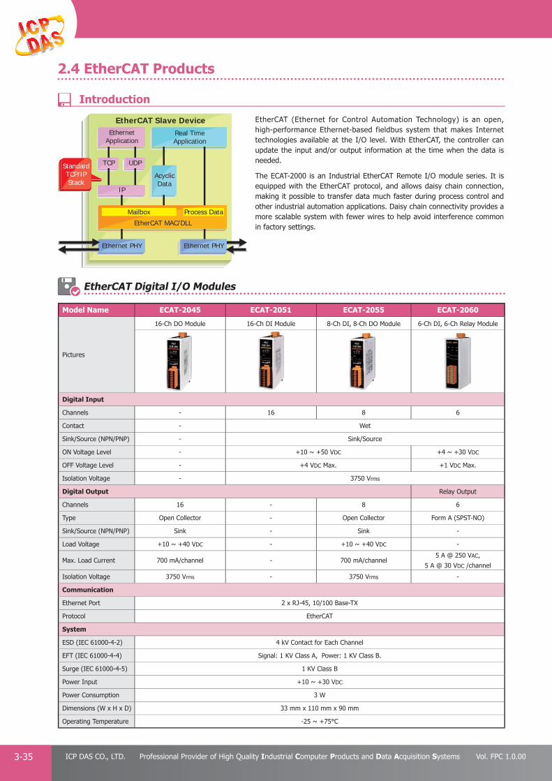
PAC Products
3-35 ICP DAS CO., LTD. Professional Provider of High Quality Industrial Computer Products and Data Acquisition Systems Vol. FPC 1.0.00
2.4 EtherCAT Products
EtherCAT (Ethernet for Control Automation Technology) is an open, high-performance Ethernet-based fieldbus system that makes Internet technologies available at the I/O level. With EtherCAT, the controller can update the input and/or output information at the time when the data is needed.
The ECAT-2000 is an Industrial EtherCAT Remote I/O module series. It is equipped with the EtherCAT protocol, and allows daisy chain connection, making it possible to transfer data much faster during process control and other industrial automation applications. Daisy chain connectivity provides a more scalable system with fewer wires to help avoid interference common in factory settings.
Model Name ECAT-2045 ECAT-2051 ECAT-2055 ECAT-2060
Pictures
16-Ch DO Module 16-Ch DI Module 8-Ch DI, 8-Ch DO Module 6-Ch DI, 6-Ch Relay Module
Digital Input
Channels - 16 8 6
Contact - Wet
Sink/Source (NPN/PNP) - Sink/Source
ON Voltage Level - +10 ~ +50 VDC +4 ~ +30 VDC
OFF Voltage Level - +4 VDC Max. +1 VDC Max.
Isolation Voltage - 3750 Vrms
Digital Output Relay Output
Channels 16 - 8 6
Type Open Collector - Open Collector Form A (SPST-NO)
Sink/Source (NPN/PNP) Sink - Sink -
Load Voltage +10 ~ +40 VDC - +10 ~ +40 VDC -
Max. Load Current 700 mA/channel - 700 mA/channel5 A @ 250 VAC,
5 A @ 30 VDC /channel
Isolation Voltage 3750 Vrms - 3750 Vrms -
Communication
Ethernet Port 2 x RJ-45, 10/100 Base-TX
Protocol EtherCAT
System
ESD (IEC 61000-4-2) 4 kV Contact for Each Channel
EFT (IEC 61000-4-4) Signal: 1 KV Class A, Power: 1 KV Class B.
Surge (IEC 61000-4-5) 1 KV Class B
Power Input +10 ~ +30 VDC
Power Consumption 3 W
Dimensions (W x H x D) 33 mm x 110 mm x 90 mm
Operating Temperature -25 ~ +75°C
EtherCAT Digital I/O Modules
EthernetApplication
IP
EtherCAT MAC/DLL
Mailbox Process Data
AcyclicData
TCP UDP
Real TimeApplication
EtherCAT Slave Device
StandardTCP/IPStack
Ethernet PHYEthernet PHY
Introduction

PAC Products
3-36E-mail: [email protected] Vol. FPC 1.0.00
Website: http://www.icpdas.com
PA
C P
rodu
cts
Pan
el P
rodu
cts
Rem
ote
I/O
M
odul
e an
d U
nit
DA
Q C
ard
Indu
stri
al
Com
mun
icat
ion
Wir
eles
s So
luti
onM
otio
n
Au
tom
atio
nA
cces
sori
esEn
ergy
M
anag
emen
tSo
luti
on
2.5 EtherNet/IP I/O Modules
Digital Input & Output Module
Model Name EIP-2042 EIP-2051 EIP-2055 EIP-2060
Pictures
16-Ch DO Module 16-Ch DI Module 8-Ch DI, 8-Ch DO Module 6-Ch DI, 6-Ch Relay Module
Digital Input
Channels
-
16 8 6
Contact Dry + Wet Dry + Wet Dry + Wet
Sink/Source (NPN/PNP) Sink/Source Sink/Source Sink/Source
Wet ContactOn Voltage Level +10 ~ 50 VDC +10 ~ 50 VDC +10 ~ 50 VDC
Off Voltage Level +4 VDC Max. +4 VDC Max. +4 VDC Max.
Dry ContactOn Voltage Level Close to GND Close to GND Close to GND
Off Voltage Level Open Open Open
Input Impedance 10 kΩ, 0.5 W 10 kΩ, 0.5 W 10 kΩ, 0.5 W
Digital Output
Channels 16
-
8 6
Type Open Collector Open Collector Power Relay
Sink/Source (NPN/PNP) Sink (NPN) Sink (NPN) Form A
Load Voltage +3.5 ~ +50 VDC +3.5 ~ +50 VDC -
Max. Switching Voltage - - 30 VDC/250 VAC
Max. Load Current 700 mA/Channel 700 mA/Channel5 A @ 30 VDC, 5 A @ 250 VAC
Overvoltage Protection 60 VDC 60 VDC -
Overload Protection Yes Yes -
Power-on Value Yes Yes Yes
Safe Value Yes Yes Yes
Analog Input Module
Model Name EIP-2017 EIP-2019
Pictures
8-ch(DIFF.)/16-ch(S.E.) analog inputs module 8-Ch Thermocouple Input Module
Analog Input
ChannelsDifferential 8 8
Single-Ended 16 -
Sensor Type - Thermocouple (J, K, T, E, R, S, B, N, C)
Voltage Input Range ±15 mV, ±50 mV, ±100 mV, ±500 mV, ±1 V, ±2.5 V, ±5 V, ±10 V
±15 mV, ±50 mV, ±100 mV, ±500 mV, ±1 V, ±2.5 V, ±5 V, ±10 V
Current Input Range ±20 mA, 0 ~ +20 mA, +4 mA ~ +20 mA (Jumper Selectable)
±20 mA, 0 ~ +20 mA, +4 mA ~ +20 mA (Jumper Selectable)
Resolution 16-bit 16-bit
Sampling Rate 10 Hz 10 Hz
Accuracy ±0.1% of FSR ±0.1% of FSR
Overvoltage Protection 240 Vrms 240 Vrms
Input Impedance 400 kΩ 400 kΩ
EDS Protection 4 kV Contact for each channel 4 kV Contact for each channel
Intra-Module Isolation 3000 VDC 3000 VDC
Model Name DI DO AI AO
EIP-2026 Channel Type Channel Type Channel Type Channel Type
2 Dry, Source 3Open Collector Sink,
700mA/Channel5
Voltage,Current (Jumper),
Thermocouple2
Voltage, Current(Jumper)
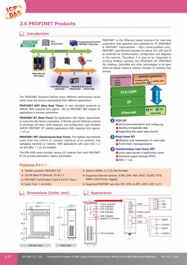
PAC Products
3-37 ICP DAS CO., LTD. Professional Provider of High Quality Industrial Computer Products and Data Acquisition Systems Vol. FPC 1.0.00
2.6 PROFINET Products
1
1
PROFINET is the Ethernet based standard for real-time automation that specified and published by PI (PROFIBUS & PROFINET International – http://www.profibus.com). PROFINET uses Ethernet standard as well as TCP, UDP and IP as protocols for communication, confi guration and diagnosis in the network. Therefore, it is easy to be integrated to existing fieldbus systems, like PROFIBUS DP, PROFIBUS PA, Interbus, DeviceNet and other technologies to an open Ethernet based network without changes to existing field devices.
The PROFINET standard defines three different performance levels which cover the various requirements from different applications.
PROFINET NRT (Non Real Time): It uses standard protocols as UDP/IP. With response time approx. 100 ms PROFINET NRT targets for applications in process automation.
PROFINET RT (Real Time): For applications with higher requirements on cycle time like factory automation, it directly uses the Ethernet protocol to exchange I/O data, while diagnosis and confi guration uses standard UDP/IP. PROFINET RT enables applications With response time approx. > 10 ms.
PROFINET IRT (Isochronous Real Time): The highest requirements come from the control of complex industrial drive systems, like packaging machines or robotics. With applications with cycle time < 1 ms and jitter < 1 μs are possible.
The PFN-2000 series provides various I/O modules that meet PROFINET RT for process automation, factory automation.
s.
Power IndicatorS1A Indicator
S1B IndicatorS2A Indicator
S2B IndicatorDigital I/O Indicator
I/O Connector
F.G.PWR
Rotary switch
LAN2
LAN1
GND
Speed
Speed
Link/Act
Link/Act
+Vs
111.0
126.0
33.090.0
107.0
37.2
35.6
37.2
7.0
Left Side View Front View
Features Transfer protocol: PROFINET I/O Generic GSDML (V 2.25) File Provided
10/100 Base-TX Ethernet, RJ-45 x 2 Supported Ethernet services: ICMP, IGMP, ARP, DHCP, TELNET, TFTP, SNMP, VLAN Priority TaggingPROFINET Conformance Class B and RT Class 1
Cyclic Time: 1 ms (min) Supported PROFINET services: RTC, RTA, CL-RPC, DCP, LLDP, I & M
AppearanceDimensions (Units: mm)
Introduction

PAC Products
3-38E-mail: [email protected] Vol. FPC 1.0.00
Website: http://www.icpdas.com
PA
C P
rodu
cts
Pan
el P
rodu
cts
Rem
ote
I/O
M
odul
e an
d U
nit
DA
Q C
ard
Indu
stri
al
Com
mun
icat
ion
Wir
eles
s So
luti
onM
otio
n
Au
tom
atio
nA
cces
sori
esEn
ergy
M
anag
emen
tSo
luti
on
Digital Input & Output Module
Model Name PFN-2042 PFN-2051 PFN-2052 PFN-2053 PFN-2055 PFN-2060
Pictures
16-Ch DO Module 16-Ch DI Module 8-Ch DI Module 16-Ch DI Module8-Ch DI,
8-Ch DO Module6-Ch DI,
6-Ch Relay Module
Digital Input
Channels
-
16 8 16 8 6
Contact Dry + Wet Wet Dry Dry + Wet Dry + Wet
Sink/Source (NPN/PNP) Sink/Source Sink/Source Source Sink/Source Sink/Source
Wet ContactOn Voltage Level +10 ~ 50 VDC +4 ~ 30 VDC - +10 ~ 50 VDC +10 ~ 50 VDC
Off Voltage Level +4 VDC Max. +1 VDC Max. - +4 VDC Max. +4 VDC Max.
Dry ContactOn Voltage Level Close to GND - Close to GND Close to GND Close to GND
Off Voltage Level Open - Open Open Open
Input Impedance 10 kΩ, 0.5 W 3KΩ, 0.3 W - 10 kΩ, 0.5 W 10 kΩ, 0.5 W
Digital Output
Channels 16
- - -
8 6
Type Open Collector Open Collector Power Relay
Sink/Source (NPN/PNP) Sink Sink Form A
Load Voltage +3.5 ~ +50 VDC +3.5 ~ +50 VDC 30 VDC/125 VAC
Max. Load Current 700 mA/Channel 700 mA/Channel 2 A @ 30 VDC, 0.6 A @ 125 VAC
Overvoltage Protection 60 VDC 60 VDC -
Overload Protection Yes Yes -
Power-on Value Yes Yes Yes
Safe Value Yes Yes Yes
Model Name Description
PROFINET I/O Module
PFN-2019 PROFINET I/O Module with 10-Ch universal AI
PFN-2024 PROFINET I/O Module with 4-Ch AO
PFN-2042 PROFINET I/O Module with 16-Ch DO
PFN-2051 PROFINET I/O Module with 16-Ch DI
PFN-2052 PROFINET I/O Module with 8-Ch DI
PFN-2053 PROFINET I/O Module with 16-Ch DI
PFN-2055 PROFINET I/O Module with 8-Ch DI, 8-Ch DO
PFN-2060 PROFINET I/O Module with 6-Ch DI, 6-Ch Relay
Analog Module
Model Name PFN-2019
Pictures
10-Ch AI Module
Analog Input
Channels 10 (Differential)
Sensor Type Thermocouple (J, K, T, E, R, S, B, N, C)
Voltage Input Range±20 mA, 0 ~ +20 mA, +4 mA ~ +20 mA
(Jumper Selectable)
Current Input Range±20 mA, 0 ~ +20 mA, +4 mA ~ +20 mA
(Jumper Selectable)
Resolution 16-bit
Sampling Rate 10 Hz
Accuracy ±0.1% of FSR
EDS Protection 4 kV Contact for each channel
Analog Module
Model Name PFN-2024
Pictures
4-Ch AO Module
Analog Output
Channels 4
Voltage Output Range 0~5 V, ±5 V, 0 ~ 10 V, ±10 V
Current Output Range 0 ~ 20 mA, 4 ~ 20 mA
Resolution 14-bit
AccuracyVoltage Output ±0.1% of FSR
Current Output ±0.2% of FSR
ESD Protection 4 kV Contact for each channel
Digital Input & Output Modules
Selection Guide

PAC Products
3-39 ICP DAS CO., LTD. Professional Provider of High Quality Industrial Computer Products and Data Acquisition Systems Vol. FPC 1.0.00
3. CAN Bus I/O ProductsC A N - 2 0 0 0 s e r i e s a n d C A N - 8 0 0 0 s e r i e s a r e d e s i g n e d fo r comb in ing sensors and ac tuators in to, CANopen or DeviceNet network. All of them provide corresponding EDS files for standard CANopen or DeviceNet master interfaces. The ma in l y d i f f e r ences be tween CAN-2000 se r i e s and CAN-8000 series are the product size and the capabilities of I/O expansion. CAN-2000 series is a palm-size and stand-along slave device. It specially suits for distribution control system, and can be placed in a limited space even in the case of machine. CAN-8000 series is useful for centralizing control system. It provides 1/2/4/8 slots for fl exible I/O selections to match various applications. Each slot allows you plugging one I-8000/I-87K series I/O module to expand I/O channels, and hot-swap technique is supported.
With the same hardware, the CAN-2000 series and CAN-8000 series can be installed either of, CANopen or DeviceNet fi rmware. The product names are classifi ed as
CANopen: CAN-8x23, CAN-2xxxC
DeviceNet: CAN-8x24, CAN-2xxxD
CAN-8000 series CAN-2000 series
1. Heartbeat MessagingThe heartbeat protocol is generally used to negotiate and monitor the availability of remote I/O devices. It is a message like the heartbeat sent by CANopen/DeviceNet remote I/O modules at a regular time. The users could use this mechanism to indicate the health of the remote I/O. The health information is most important in the industrial applications. All the CANopen/DeviceNet remote I/O series from ICP DAS has the heartbeat protocol to increase the reliability of the remote data.
2. Safety & ArbitrationCAN bus provides fi ve mechanisms for achieving the utmost safety of data transfer. There are powerful for error detection, signaling and self-checking are implemented in every CAN node. If two or more nodes start transmitting messages at the same time, the arbitration mechanism is applied to guarantee that one of these messages can be sent successfully according to the priority.
3. Auto Response of Input DataThe input data of CANopen/DeviceNet I/O modules allows to be responded automatically by event trigger or timer trigger. For example, DI data will be responded to the master when the DI data is changed. The AI data can be responded cyclically by predefi ned time period.
4. CANopen Digital I/O Pair-ConnectionCANopen Digital I/O Pair-Connection is a special function for CANopen remote I/O. It can send the DI value that detected by the CANopen DI slave to other CANopen DO slaves through the CANopen network, and then these CANopen DO slaves will output the value. It is useful for users who need to detect a DI signal and output a DO alarm in time.
CANopen/DeviceNet Network CANopen/DeviceNet Network
Event Trigger
DI1
0 t 2t 3tAI
Timer Trigger
Features

PAC Products
3-40E-mail: [email protected] Vol. FPC 1.0.00
Website: http://www.icpdas.com
PA
C P
rodu
cts
Pan
el P
rodu
cts
Rem
ote
I/O
M
odul
e an
d U
nit
DA
Q C
ard
Indu
stri
al
Com
mun
icat
ion
Wir
eles
s So
luti
onM
otio
n
Au
tom
atio
nA
cces
sori
esEn
ergy
M
anag
emen
tSo
luti
on
Model Name ProtocolAnalog Input Analog output
Channels Input Range Sensor Channels Output Range
CAN-2015C CANopen8 -
RTD (Pt100, Pt1000,
Ni120, Cu100, Cu1000,
Pt100)-
CAN-2015D DeviceNet
CAN-2017C CANopen8
±10 V, ±5 V, ±1 V, ±500 mV,
±150 mV, ±20 mA
(with external 125 Ω resistor)-
CAN-2017D DeviceNet
CAN-2018C CANopen8
±2.5 V, ±1 V, ±500 mV, ±100 mV,
±50 mV, ±15 mV, ±20 mA
(with external 125 Ω resistor)
Thermocouple
(J, K, T, E. R. S, B, N, C)-
CAN-2018D DeviceNet
CAN-2024C CANopen- 4
0 ~ +5 V, ±5 V, 0 ~ +10 V,
±10 V, 0 ~ 20 mA, +4 ~ 20 mACAN-2024D DeviceNet
Model Name ProtocolAnalog Input Analog output
Channels Contact Counter Channels Type Sin/source
CAN-2053C CANopen16 wet - - - -
CAN-2053D DeviceNet
CAN-2054C CANopen8 wet - 8 Open Collector sink
CAN-2054D DeviceNet
CAN-2057C CANopen- - - 16 Open Collector sink
CAN-2057D DeviceNet
CAN-2088C CANopen8 wet 32-bit, max 500 kHz - - -
CAN-2088D DeviceNet
Analog I/O Modules
Digital I/O Modules
CANopen DS 301 Ver 4.02/DS 401 Ver 2.1 Specifi cation
DeviceNet Volume I Ver 2.0, Volume II Ver2.0
CAN Bus I/O Unit
Model Name Interface
CAN-8123-G CANopen Embedded Device with 1 I/O Expansion Slot
CAN-8223-G CANopen Embedded Device with 2 I/O Expansion Slots
CAN-8423-G CANopen Embedded Device with 4 I/O Expansion Slots
CAN-8823-G CANopen Embedded Device with 8 I/O Expansion Slots
Model Name Interface
CAN-8124-G DeviceNet Embedded Device with 1 I/O Expansion Slot
CAN-8224-G DeviceNet Embedded Device with 2 I/O Expansion Slots
CAN-8424-G DeviceNet Embedded Device with 4 I/O Expansion Slots
CAN-8824-G DeviceNet Embedded Device with 8 I/O Expansion Slots

PAC Products
3-41 ICP DAS CO., LTD. Professional Provider of High Quality Industrial Computer Products and Data Acquisition Systems Vol. FPC 1.0.00
4. PROFIBUS I/O ProductsPROFIBUS (Process Field Bus) is a standard for fieldbus communication in automation technology and was first promoted (1989) by BMBF (German department of education and research). It is the world's most successful fi eldbus, with more than 31 million devices installed by the end of 2009. Over 5.4 million of these were in the process industries.
Features
There are two variations of PROFIBUS in use today. The most commonly used PROFIBUS DP, and the lesser used PROFIBUS PA.
PROFIBUS DP (Decentralized Peripherals) It is used to operate sensors and actuators via a centralized controller in production (factory) automation applications.
PROFIBUS PA (Process Automation) It is used to monitor measuring equipment via a process control system in process automation applications. This variant is designed for use in explosion/hazardous areas.
ICP DAS has been developing various PROFIBUS DP Slave products for several years. We offer converters, gateways, and remote I/O to our customers, and help them to solve technology problems.
Model Name Description
Remote I/O Modules
PROFI-5017 PROFIBUS-DP I/O Module with 8-Ch Voltage Inputs
PROFI-5017C PROFIBUS-DP I/O Module with 8-Ch Current Inputs
PROFI-5018 PROFIBUS-DP I/O Module with 10-Ch Thermocouple Inputs
PROFI-5024 PROFIBUS-DP I/O Module with 4-Ch Voltage/Current Outputs
PROFI-5045 PROFIBUS-DP I/O Module with 24-Ch DO
PROFI-5050 PROFIBUS-DP I/O Module with 16-Ch DI, 8-Ch DO
PROFI-5051 PROFIBUS-DP I/O Module with 24-Ch DI
PROFI-5052 PROFIBUS-DP I/O Module with 12-Ch DI
PROFI-5053 PROFIBUS-DP I/O Module with 24-Ch DI
PROFI-5055 PROFIBUS-DP I/O Module with 8-Ch DI, 8-Ch DO
PROFI-5060 PROFIBUS-DP I/O Module with 8-Ch DI, 6-Ch Relay
Remote I/O units
PROFI-8155 PROFIBUS-DP I/O Unit with 1 I/O slot
PROFI-8255 PROFIBUS-DP I/O Unit with 2 I/O slots
PROFI-8455 PROFIBUS-DP I/O Unit with 4 I/O slots
PROFI-8855 PROFIBUS-DP I/O Unit with 8 I/O slots
Accessories CNT-PROFI PROFIBUS 9-pin D-Sub Male Connector
Baudrate up to 12 Mbit/s. Allow Multi-master system.
Maximum 244 bytes input and 244 bytes output per slave. 124 slaves can be put in Data Exchange.
Fast Cyclic data communication between master and slave. 32 stations on one segment.
Slave confi guration and parameters are set from the master side by GSD fi le.
Selection Guide

PAC Products
3-42E-mail: [email protected] Vol. FPC 1.0.00
Website: http://www.icpdas.com
PA
C P
rodu
cts
Pan
el P
rodu
cts
Rem
ote
I/O
M
odul
e an
d U
nit
DA
Q C
ard
Indu
stri
al
Com
mun
icat
ion
Wir
eles
s So
luti
onM
otio
n
Au
tom
atio
nA
cces
sori
esEn
ergy
M
anag
emen
tSo
luti
on
PROFIBUS Analog Input Modules
Model Name PROFI-5017 PROFI-5017C PROFI-5018
Pictures
8-Ch Voltage Input Module 8-Ch Current Input Module 10-Ch Thermocouple Input Module
Channels 8 8 10
Wiring Differential Differential Differential
Individual Channel Yes Yes Yes
Sensor Type - -Thermocouple
(J, K, T, E. R. S, B, N, C)
Voltage Input Range
±10 V
±5 V
±2.5 V
±1.25 V
-
±2.5 V
±1 V
±500 mV
±100 mV
±50 mV
±15 mV
Current Input Range - ±20 mA±20 mA
(Required External 125 Ω Resistor)
Resolution 14-bit 14-bit 16-bit
Sampling Rate 10 Hz 10 Hz 10 Hz
Accuracy ±0.1 % of FSR ±0.2 % of FSR ±0.1 % of FSR
Zero Drift ±0.5 μV/ °C ±10 μV/ °C ±0.5 μV/ °C
Span Drift ±20 μV/ °C ±25 μV/ °C ±25 ppm
Overvoltage Protection 120 VDC / 110 VAC 240 Vrms N/A
Input Impedance 20 MΩ 2 MΩ 20 kΩ
Common Mode Rejection 150 dB 86 dB 150 dB
Normal Mode Rejection 100 dB 100 dB 100 dB
PROFIBUS Analog Output Modules
Model Name PROFI-5024
Pictures
4-Ch Voltage/Current Output Module
Channels 4
Wiring Differential
Voltage Output Range ±10 V
Current Output Range 0 ~ 20 mA, 4 ~ 20 mA
Resolution 14-bit
AccuracyFor Voltage Output ±0.1% of FSR
For Current Output ±0.2% of FSR
Isolation 3000 VDC
4.1 PROFIBUS Remote I/O Modules

PAC Products
3-43 ICP DAS CO., LTD. Professional Provider of High Quality Industrial Computer Products and Data Acquisition Systems Vol. FPC 1.0.00
PROFIBUS Digital I/O Modules
Model Name PROFI-5045 PROFI-5050 PROFI-5051 PROFI-5052 PROFI-5053 PROFI-5055 PROFI-5060
Pictures
DI
Channels
-
16 24 12 24 8 8
Isolation Voltage - 3750 Vrms 5000 Vrms - 3750 Vrms 3750 Vrms
Contact Dry Wet Wet Dry Wet Wet
Sink/Source (NPN/PNP) Sink/Source Sink/Source Sink/Source - Sink/Source Sink/Source
ON Voltage Level +4 ~ +30 VDC +10 ~ +50 VDC +4 ~ +30 VDC Open +10 ~ +50 VDC +4 ~ +30 VDC
OFF Voltage Level +1 VDC Max. +4 VDC Max. +1 VDC Max. Close to IN.GND +4 VDC Max. +1 VDC Max.
Input Impedance - 10 KΩ 3 KΩ - 10 KΩ 3 KΩ
DO
Channels 24 8
- - -
8 4
Isolation Voltage 3750 Vrms - 3750 Vrms -
Type Open Collector Open Collector Open Collector Relay (Form C)
Sink/Source (NPN/PNP) Sink Sink Sink -
Load Voltage +10 ~ +40 VDC +10 ~ +30 VDC +10 ~ +40 VDC0 ~ 125 VDC
0 ~ 30 VDC
Max. Load Current 650mA/channel 30 mA/channel 650 mA/channel0.6 A @ 125 VDC
2 A @ 30 VDC
Communication
Connector 9-pin female D-Sub
Baud Rate (bps) 9.6 k, 19.2 k, 45.45 k, 93.75 k, 187.5 k, 500 k, 1.5 M, 3 M, 6 M, 12 M
Controller Profi chip VPCLS2
Transceiver ADI ADM2486
Protocol DP-V0
Node Address 0 ~ 99 selected by rotary switch
4.2 PROFIBUS Remote I/O Units
The PROFI-8x55 Remote I/O Unit is designed for the slave device of PROFIBUS DP protocol. It supports up to 1/2/4/8 slots for ICPDAS I-8k, I-87k series I/O modules. In addition, we also provide hot-swap function for I-87k High Profi les series I/O modules. To setup network, users can choose and confi gure I/O modules by using the GSD fi le without any other setting tools.
PROFI-8155-G CR PROFIBUS Remote I/O Unit with 1 Expansion Slot (RoHS)
PROFI-8255-G CR PROFIBUS Remote I/O Unit with 2 Expansion Slots (RoHS)
PROFI-8455-G CR PROFIBUS Remote I/O Unit with 4 Expansion Slots (RoHS)
PROFI-8855-G CR PROFIBUS Remote I/O Unit with 8 Expansion Slots (RoHS)
PROFI-8255 PROFI-8855PROFI-8155 PROFI-8455 PROFI 8855
Features Protocol & hierarch y: DP-V0 & DP-V1 Slave 3000 VDC Isolation Protection on PROFIBUS side
Detect transmission Rate Automatically (Max.12 Mbps) 1/2/4/8 I/O Slots for I-87K and I-8K Series I/O Modules
Support Device-Related & Channel-Related Diagnosis 4 KV ESD Protection (contacting for any terminal)
Address 0 ~ 126 Set by Rotary Switches or SSA-Telegram Operating Temperature: -25 ~ +75°C
Support Hot-Swap for I-87K High-Profi le I/O Modules
Ordering Information
Introduction
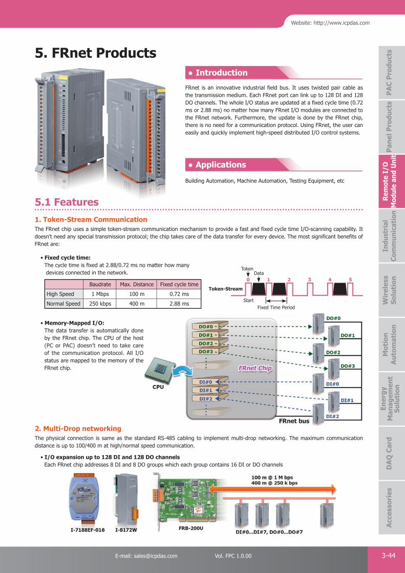
PAC Products
3-44E-mail: [email protected] Vol. FPC 1.0.00
Website: http://www.icpdas.com
PA
C P
rodu
cts
Pan
el P
rodu
cts
Rem
ote
I/O
M
odul
e an
d U
nit
DA
Q C
ard
Indu
stri
al
Com
mun
icat
ion
Wir
eles
s So
luti
onM
otio
n
Au
tom
atio
nA
cces
sori
esEn
ergy
M
anag
emen
tSo
luti
on
5. FRnet Products
1. Token-Stream CommunicationThe FRnet chip uses a simple token-stream communication mechanism to provide a fast and fixed cycle time I/O-scanning capability. It doesn't need any special transmission protocol; the chip takes care of the data transfer for every device. The most significant benefits of FRnet are:
• Fixed cycle time: The cycle time is fi xed at 2.88/0.72 ms no matter how many devices connected in the network.
Baudrate Max. Distance Fixed cycle time
High Speed 1 Mbps 100 m 0.72 ms
Normal Speed 250 kbps 400 m 2.88 ms
2. Multi-Drop networkingThe physical connection is same as the standard RS-485 cabling to implement multi-drop networking. The maximum communication distance is up to 100/400 m at high/normal speed communication.
• I/O expansion up to 128 DI and 128 DO channelsEach FRnet chip addresses 8 DI and 8 DO groups which each group contains 16 DI or DO channels
● Applications
● Introduction
FRnet is an innovative industrial fi eld bus. It uses twisted pair cable as the transmission medium. Each FRnet port can link up to 128 DI and 128 DO channels. The whole I/O status are updated at a fi xed cycle time (0.72 ms or 2.88 ms) no matter how many FRnet I/O modules are connected to the FRnet network. Furthermore, the update is done by the FRnet chip, there is no need for a communication protocol. Using FRnet, the user can easily and quickly implement high-speed distributed I/O control systems.
Building Automation, Machine Automation, Testing Equipment, etc
Token-Stream
Fixed Time PeriodStart
TokenData
0 1 2 3 4 5
• Memory-Mapped I/O:The data transfer is automatically done by the FRnet chip. The CPU of the host (PC or PAC) doesn’t need to take care of the communication protocol. All I/O status are mapped to the memory of the FRnet chip.
5.1 Features
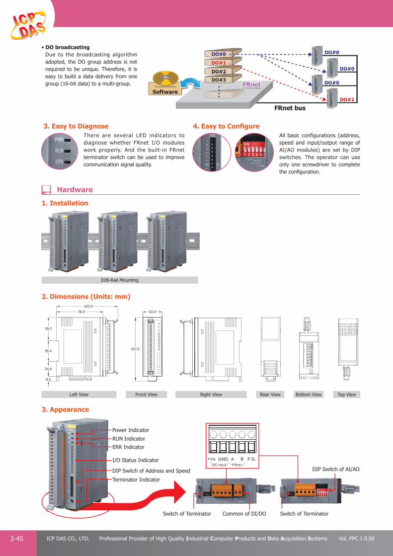
PAC Products
3-45 ICP DAS CO., LTD. Professional Provider of High Quality Industrial Computer Products and Data Acquisition Systems Vol. FPC 1.0.00
3. Appearance
1. Installation
• DO broadcastingDue to the broadcasting algorithm adopted, the DO group address is not required to be unique. Therefore, it is easy to build a data delivery from one group (16-bit data) to a multi-group.
2. Dimensions (Units: mm)
Bottom View Top ViewLeft View
DIN-Rail Mounting
Front View Right View Rear View
107.0
33.0
102.0
78.0
39.0
35.4
24.6
8.0
Power Indicator
RUN Indicator
I/O Status Indicator
Switch of Terminator Switch of TerminatorCommon of DI/DO
DIP Switch of AI/AO DIP Switch of Address and Speed
Terminator Indicator
ERR Indicator
3. Easy to DiagnoseThere are several LED indicators to diagnose whether FRnet I/O modules work properly. And the built-in FRnet terminator switch can be used to improve communication signal quality.
4. Easy to Confi gureAll basic configurations (address, speed and input/output range of AI/AO modules) are set by DIP switches. The operator can use only one screwdriver to complete the confi guration.
Hardware

PAC Products
3-46E-mail: [email protected] Vol. FPC 1.0.00
Website: http://www.icpdas.com
PA
C P
rodu
cts
Pan
el P
rodu
cts
Rem
ote
I/O
M
odul
e an
d U
nit
DA
Q C
ard
Indu
stri
al
Com
mun
icat
ion
Wir
eles
s So
luti
onM
otio
n
Au
tom
atio
nA
cces
sori
esEn
ergy
M
anag
emen
tSo
luti
on
NEWNEW
Digital Input Module
Model Name FR-2053iT FR-2053TA FR-2053HTA FR-2054T FR-2057iT FR-2057TW FR-32R
Pictures
Digital Input
Channels 16 8 - -
Type Wet Wet - -
Sink/Source (NPN/PNP) Sink/Source Sink/Source - -
Isolation 3750 Vrms 3750 Vrms - -
On Voltage Level 19 ~ 30 VDC 3.5 ~ 30 VDC 19 ~ 30 VDC - -
Off Voltage Level 11 VDC Max. 1 VDC Max. 11 VDC Max. - -
Input Impedance 3.25 KΩ 3 KΩ 3.25 KΩ - -
Digital Output
Channels - 8 16 32
Type - Open Collector Open CollectorPower Relay
(Form A, SPST)
Sink/Source (PNP/NPN) - Sink (NPN) Sink (NPN) -
Isolation - 3750 Vrms 3750 Vrms 3000 Vrms
Load Voltage - 5 ~ 30 VDC 5 ~ 30 VDC 3A/125 VDC, 3A/270 VACMax. Load Current - 250 mA 100 mA 250 mA
FRnet Communication
Normal Speed
Update time 2.88 ms
Yes Yes - Yes Yes YesYes
(default)Baud rate 250 Kbps
Distance 400 m Max.
High Speed
Update time 0.72 msYes
(default)- Yes
Yes (default)
Yes (default)
Yes (default)
YesBaud rate 1 Mbps
Distance 100 m Max.
Analog Input Module Analog Output Module
Model Name FR-2017iT FR-2024iT
Pictures
Channels 1 or 8/16 4
Wiring Differential/Single-Ended Bipolar/Unipolar
Voltage Range ±150 mV, ± 500 mV, ± 1V, ±5 V, ±10 V 0 ~ 5V, ±5 V, 0 ~ 10 V, ±10 V
Current Range±20 mA, 0 ~ 20 mA, 4 ~ 20 mA;
Requires optional external 125 Ω resistors0 ~ 20 mA, 4 ~ 20 mA
Resolution 16-bit(1 channel) or 12-bit (8/16 channels) 12-bit
Accuracy ± 0.1% (1 channel) or ± 0.5% (8/16 channel) of FSR ±0.1% of FSR
Sampling Rate 10 Hz (1 channel) / 50 Hz (8/16 channels); for total channels -
Input Impedance 2 MΩ (differential), 1 MΩ (single-ended) -
Common Voltage Protection 200 VDC -
Output Capacity -Voltage: 10 VDC @ 20 mA
Current: External 24 VDC @ 1050 Ω
Output Slew Rate -Immediately Output (default) or 0.0625 ~ 1024 V/second (by Software)Immediate Output (default) or 0.125 ~ 2048 mA/second (by Software)
Individual Channel Confi guration Yes (by software, requires optional CA-0904 cable) Yes (by software)
Overvoltage Protection 240 Vrms (differential), 150 Vrms (single-ended) ±15 VDC
FRnet Communication
Normal Speed
Update time 2.88 ms
YesBaud rate 250 Kbps
Distance 400 m Max.
High Speed
Update time 0.72 ms
Yes (default)Baud rate 1 Mbps
Distance 100 m Max.
5.2 FRnet I/O Modules
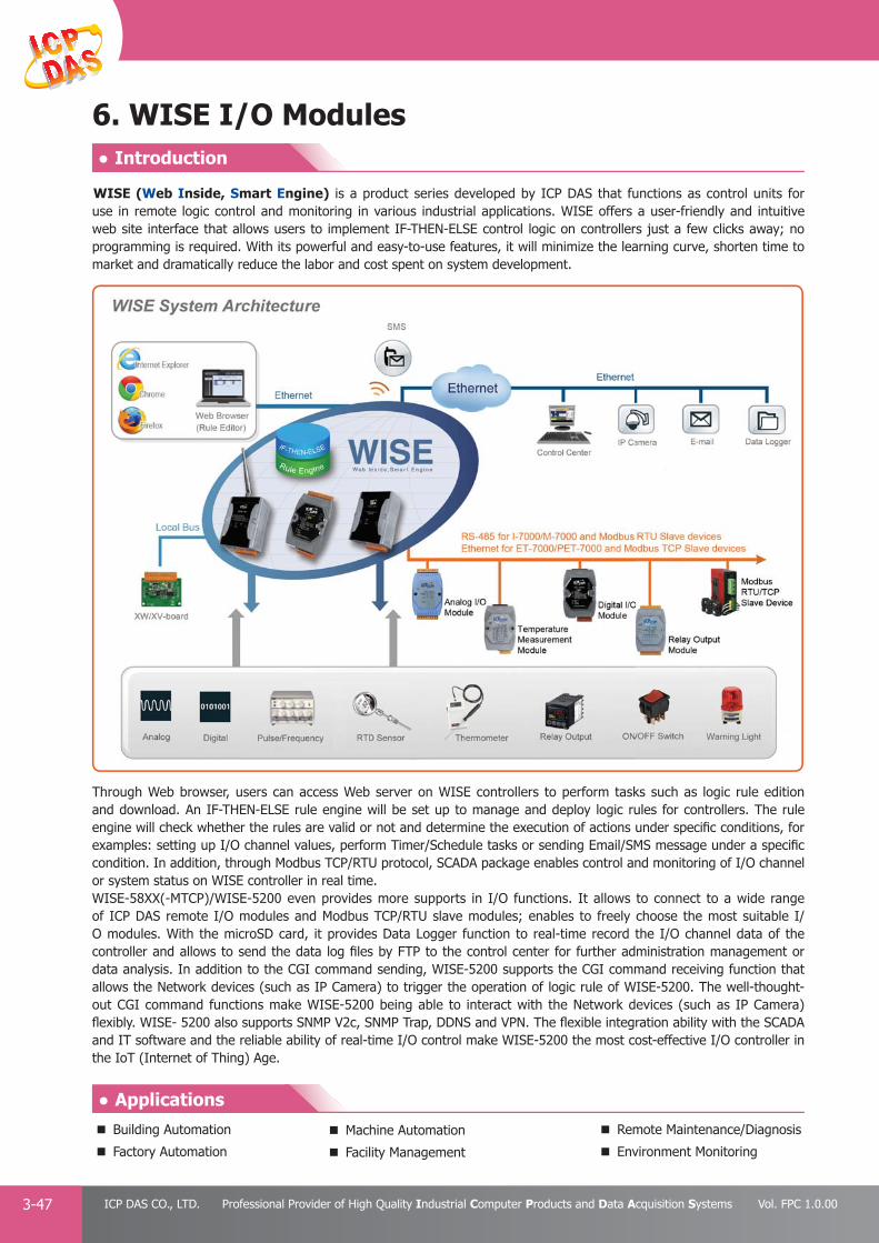
PAC Products
3-47 ICP DAS CO., LTD. Professional Provider of High Quality Industrial Computer Products and Data Acquisition Systems Vol. FPC 1.0.00
6. WISE I/O Modules
● Applications
● Introduction
Through Web browser, users can access Web server on WISE controllers to perform tasks such as logic rule edition and download. An IF-THEN-ELSE rule engine will be set up to manage and deploy logic rules for controllers. The rule engine will check whether the rules are valid or not and determine the execution of actions under specifi c conditions, for examples: setting up I/O channel values, perform Timer/Schedule tasks or sending Email/SMS message under a specifi c condition. In addition, through Modbus TCP/RTU protocol, SCADA package enables control and monitoring of I/O channel or system status on WISE controller in real time.WISE-58XX(-MTCP)/WISE-5200 even provides more supports in I/O functions. It allows to connect to a wide range of ICP DAS remote I/O modules and Modbus TCP/RTU slave modules; enables to freely choose the most suitable I/O modules. With the microSD card, it provides Data Logger function to real-time record the I/O channel data of the controller and allows to send the data log fi les by FTP to the control center for further administration management or data analysis. In addition to the CGI command sending, WISE-5200 supports the CGI command receiving function that allows the Network devices (such as IP Camera) to trigger the operation of logic rule of WISE-5200. The well-thought-out CGI command functions make WISE-5200 being able to interact with the Network devices (such as IP Camera) flexibly. WISE- 5200 also supports SNMP V2c, SNMP Trap, DDNS and VPN. The flexible integration ability with the SCADA and IT software and the reliable ability of real-time I/O control make WISE-5200 the most cost-effective I/O controller in the IoT (Internet of Thing) Age.
WISE (Web Inside, Smart Engine) is a product series developed by ICP DAS that functions as control units for use in remote logic control and monitoring in various industrial applications. WISE offers a user-friendly and intuitive web site interface that allows users to implement IF-THEN-ELSE control logic on controllers just a few clicks away; no programming is required. With its powerful and easy-to-use features, it will minimize the learning curve, shorten time to market and dramatically reduce the labor and cost spent on system development.
Building Automation
Factory Automation
Machine Automation
Facility Management
Remote Maintenance/Diagnosis
Environment Monitoring

PAC Products
3-48E-mail: [email protected] Vol. FPC 1.0.00
Website: http://www.icpdas.com
PA
C P
rodu
cts
Pan
el P
rodu
cts
Rem
ote
I/O
M
odul
e an
d U
nit
DA
Q C
ard
Indu
stri
al
Com
mun
icat
ion
Wir
eles
s So
luti
onM
otio
n
Au
tom
atio
nA
cces
sori
esEn
ergy
M
anag
emen
tSo
luti
on
IF-THEN-ELSE logic rules execution abilityWISE controller features an IF-THEN-ELSE logic rule engine, it offers IF-THEN-ELSE rules for users to set up the logic content. After completing rule edition and downloading rules to the WISE controller, the rule engine will loop execute the rules in accordance with the execution order under specifi c conditions.
No extra software tool is requiredWISE HMI interface runs on regular Web browsers. To edit control logic, it only requires a browser to connect to the Web server on WISE controller. No extra software tool installation is needed on the target PC.
No more programmingWISE provides user-friendly Web UI pages for editing control logic on the controllers. It enables implementation of logic edition by a few clicks on the mouse to set up and deploy logic rules without writing a single line of code.
Offer various options for I/O channel settingsWISE offers various options for I/O channel settings; for example: noise fi lter for DI signals, deadband setting for AI signals, linear scale setting, temperature degree in Celsius or Fahrenheit setting, power on value setting for DO channel, pulse output setting and DI/DO counter setting, etc.
▲ WISE Web User Interface ▲ Click and get done!
WISEIF-THEN-ELSE
Rule Engine
▲The function overview of IF-THEN-ELSE rule engine
IF Conditions
DI Channel ON, OFF, ON to OFF, OFF to ON, Change
AI Channel
=, >, <, >=, <= (value)Internal Register
CGI Variable
DI Counter=, >, <, >=, <= (value), Change
DO Counter
Timer Timeout, Not Timeout
Schedule In Range, Out of Range
Rule Status Enable, Disable THEN / ELSE Actions
DO Channel ON, OFF, Pulse Output
AO ChannelChange the value
Internal Register
DI CounterReset
DO Counter
Timer Start, Reset
SMS
SendEmail
CGI Command
SNMP Trap
Data Logger Start, Stop, One-Time Log
Rule Status Enable, Disable
6.1 Features
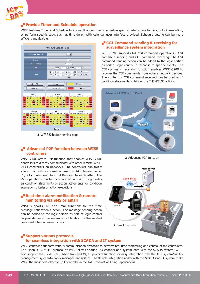
PAC Products
3-49 ICP DAS CO., LTD. Professional Provider of High Quality Industrial Computer Products and Data Acquisition Systems Vol. FPC 1.0.00
Advanced P2P function between WISE controllers WISE-71XX offers P2P function that enables WISE-71XX controllers to directly communicate with other remote WISE-71XX controllers on networks. The controllers can freely share their status information such as I/O channel value, DI/DO counter and Internal Register to each other. The P2P operations can be incorporated into WISE logic rules as condition statements or action statements for condition evaluation criteria or action executions.
Real-time alarm notifi cation & remote monitoring via SMS or EmailWISE supports SMS and Email functions for real-time message notifi cation function. The message sending action can be added to the logic edition as part of logic control to provide real-time message notification to the related personnel when an event occurs.
Support various protocols for seamless integration with SCADA and IT systemWISE controller supports various communication protocols to perform real-time monitoring and control of the controllers. The Modbus TCP/RTU protocol of WISE allows sharing I/O channel and system data with the SCADA system. WISE also support the SNMP V2c, SNMP Trap and MQTT protocol function for easy integration with the MIS system/Facility management system/Network management system. The flexible integration ability with the SCADA and IT system make WISE the most cost-effective I/O controller in the IoT (Internet of Thing) applications.
IT t
▲ Advanced P2P function
▲ Email function
Provide Timer and Schedule operationWISE features Timer and Schedule functions: It allows user to schedule specifi c date or time for control logic execution, or perform specific tasks such as time delay. With calendar user interface provided, Schedule setting can be more effi cient and fl exible.
CGI Command sending & receiving for surveillance system integration WISE-5200 supports full CGI command operations - CGI command sending and CGI command receiving. The CGI command sending action can be added to the logic edition as part of logic control in response to specifi c events. The CGI command receiving function enables WISE-5200 to receive the CGI commands from others network devices. The content of CGI command received can be used in IF condition statements to trigger the THEN/ELSE actions.
▲ WISE Schedule setting page

PAC Products
3-50E-mail: [email protected] Vol. FPC 1.0.00
Website: http://www.icpdas.com
PA
C P
rodu
cts
Pan
el P
rodu
cts
Rem
ote
I/O
M
odul
e an
d U
nit
DA
Q C
ard
Indu
stri
al
Com
mun
icat
ion
Wir
eles
s So
luti
onM
otio
n
Au
tom
atio
nA
cces
sori
esEn
ergy
M
anag
emen
tSo
luti
on
WISE-5801(-MTCP) controller is equipped with SMS command receiving function. It allows to receive the SMS commands sent by specifi c phone numbers to perform tasks such as real-time I/O channel value monitoring, I/O channel value modification and logic rules execution (triggered by SMS), etc.
Support Modbus TCP/RTU slave moduleWISE Controller allows to connect with devices that support Modbus TCP/RTU protocol for I/O monitoring. The ability to connect with Modbus TCP/RTU slave devices enables the fl exibility and scalability for system implementation and allows to meet various requirements of the applications from the clients.
▲ SMS alarm notifi cation
Active I/O sending mechanismIn addition to the Modbus TCP/RTU slave function that enables SCADA software to pol l the I/O channel data of the WISE controller, now WISE provides “Active I/O sending” mechanism (Modbus TCP master and SNMP Trap). Based on the “Active I/O sending”, WISE allows to send the I/O channel data of the controller actively to SCADA/MIS/Facility Management/Network Management system by event trigger (change of the I/O channel data) or periodic cycle. This function will improve the efficiency of the data communication between WISE and IT/SCADA software.
Note:Based on Modbus TCP protocol, the SCADA software must be able to provide Modbus TCP slave function to receive the I/O channel data sent by WISE-58XX(-MTCP) or WISE-5200.
▲ Active I/O sending mechanism
Data Logger operationWith the microSD card, WISE provides Data Logger function to real-time record the I/O channel data of the controller and sends the data fi les by FTP or Email to the control center for further administration management or data analysis.
▲ Data Logger function
Note:1. WISE-58XX can connect to ICP DAS XW-board, I-7000/
M-7000 series modules, DL series modules or Modbus RTU slave modules.
2. WISE-58XX-MTCP can connect to ICP DAS XW-board, ET-7000/PET-7000 series modules, WISE-71xx series modules or Modbus TCP slave modules.
3. WISE-5200 can connect to ICP DAS XV-board, I-7000/DL modules, M-7000/tM/DL/LC/SC/IR modules, WISE-7100/(P)ET-7000/WF-2000 modules and Modbus TCP/RTU slave modules.
Real-time receive and execute SMS command

PAC Products
3-51 ICP DAS CO., LTD. Professional Provider of High Quality Industrial Computer Products and Data Acquisition Systems Vol. FPC 1.0.00
Why WISE ? No extra software tool is required; all operations can be done through the Web browser
No programming is required. Dramatically reduce the labor and cost spent on system development
Provide various hardware platforms and wide range of I/O modules that allows users to fi nd best solutions
IF-THEN-ELSE logic rules execution ability
Fully automation functions supported
• I/O channel monitoring and control
• Timer/Schedule operation
• SMS/Email message sending
• CGI Command sending and receiving function supported for IP Camera and Network device
• SMS command receiving to perform the tasks triggered by SMS.
• Seamless integration with SCADA through Modbus TCP/RTU protocol
• Automatically perform data logger operation and send back data fi les
• Active I/O operation for effi cient data communication
• SNMP V2c protocol, SNMP Trap, DDNS and VPN function supported
WISE Comparison Table
Item\Product Series WISE-71XX WISE-58XX(-MTCP) WISE-5200
CPU 16-Bit CPU 32-Bit CPU
Network Interface 10/100 Base-TX with PoE 10/100 Base-TX 10/100/1000 Base-TX
Micro SD Interface - Yes Yes
I/OModule Support
Local I/O Built-in with XW-board with XV-board
Remote I/O -I-7000 or
Modbus RTU Slave or Modbus TCP Slave Device
DCON & Modbus RTU Slave &
Modbus TCP Slave Device
Rule Confi guration Website Yes Yes Yes
IF-THEN-ELSE Logic Rule Yes Yes Yes
I/O Channel Operation Yes Yes Yes
Timer Operation Yes Yes Yes
Connect with SCADA SoftwareYes
(Support Modbus TCP)Yes (Support
Modbus TCP/RTU)Yes (Support
Modbus TCP/RTU)
Email Message Sending Yes (non-SSL) Yes (non-SSL) Yes (non-SSL & SSL)
Schedule Operation - Yes Yes (more powerful)
Active I/O Operation - Yes Yes
Data Logger Operation - Yes (one set) Yes (more sets)
FTPClient - Yes Yes
Server - - Yes
CGI Command
Sending Yes Yes Yes (more powerful)
Receiving - - Yes
SNMP v2c & SNMP Trap - - Yes
VPN, DDNS - - Yes
MQTT - - Yes
P2P Supported Yes - -
SMS Operation -Yes,
by WISE-5801(-MTCP)-
Hard
ware
So
ftware Fu
nctio
n
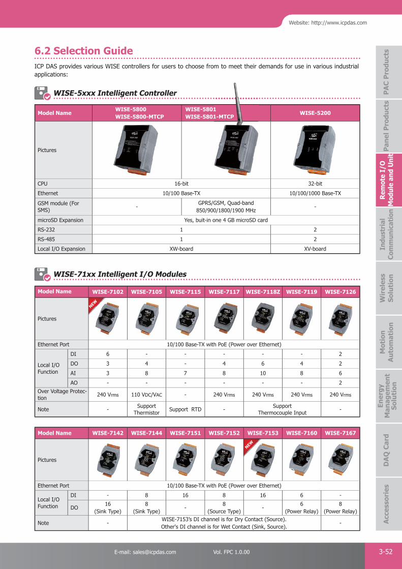
PAC Products
3-52E-mail: [email protected] Vol. FPC 1.0.00
Website: http://www.icpdas.com
PA
C P
rodu
cts
Pan
el P
rodu
cts
Rem
ote
I/O
M
odul
e an
d U
nit
DA
Q C
ard
Indu
stri
al
Com
mun
icat
ion
Wir
eles
s So
luti
onM
otio
n
Au
tom
atio
nA
cces
sori
esEn
ergy
M
anag
emen
tSo
luti
on
NEW
NEW
ICP DAS provides various WISE controllers for users to choose from to meet their demands for use in various industrial applications:
Model Name WISE-7102 WISE-7105 WISE-7115 WISE-7117 WISE-7118Z WISE-7119 WISE-7126
Pictures
Ethernet Port 10/100 Base-TX with PoE (Power over Ethernet)
Local I/O Function
DI 6 - - - - - 2
DO 3 4 - 4 6 4 2
AI 3 8 7 8 10 8 6
AO - - - - - - 2
Over Voltage Protec-tion
240 Vrms 110 VDC/VAC - 240 Vrms 240 Vrms 240 Vrms 240 Vrms
Note -Support
ThermistorSupport RTD -
Support Thermocouple Input
-
W
Model Name WISE-7142 WISE-7144 WISE-7151 WISE-7152 WISE-7153 WISE-7160 WISE-7167
Pictures
Ethernet Port 10/100 Base-TX with PoE (Power over Ethernet)
Local I/O Function
DI - 8 16 8 16 6 -
DO16
(Sink Type)8
(Sink Type)-
8(Source Type)
-6
(Power Relay)8
(Power Relay)
Note -WISE-7153’s DI channel is for Dry Contact (Source).Other's DI channel is for Wet Contact (Sink, Source).
-
W
6.2 Selection Guide
Model NameWISE-5800WISE-5800-MTCP
WISE-5801WISE-5801-MTCP
WISE-5200
Pictures
CPU 16-bit 32-bit
Ethernet 10/100 Base-TX 10/100/1000 Base-TX
GSM module (For SMS)
-GPRS/GSM, Quad-band
850/900/1800/1900 MHz-
microSD Expansion Yes, buit-in one 4 GB microSD card
RS-232 1 2
RS-485 1 2
Local I/O Expansion XW-board XV-board
WISE-71xx Intelligent I/O Modules
WISE-5xxx Intelligent Controller
11-MTCP

PAC Products
3-53 ICP DAS CO., LTD. Professional Provider of High Quality Industrial Computer Products and Data Acquisition Systems Vol. FPC 1.0.00
6.3 I/O Expansion for WISE-580x
I/O Expansion Boards (XW-board) for WISE-58xx(-MTCP)
I/O Expansion Boards (XV-board) for WISE-5200
DI, DO Expansion
Model Name DI DO Isolation
XW1078 8
-
XW107i 3750 Vrms
XW110i 16 - 3750 Vrms
AI, AO, DI, DO Expansion
Model Name AI (12-bit) AO (12-bit)
DI DO IsolationCh Range Ch Range
XW304 6 ±5 V 1 ±5 V 4 4
-XW310 4 ±10 V 2 ±10 V 3 3
XW310C 4 0 ~ 20 mA 2 0 ~ 20 mA 3 3
I-7000 Remote I/O Module AI/AO Module
Model Name AI AO DI DO
Voltage/CurrentI-7012 1 - 1 2
I-7017 8 - - -
Thermocouple
I-7011 1 - 1 2
I-7018 8 - - -
I-7019 8 - - -
RTD
I-7013 1 - - -
I-7015 6 - - -
I-7033 3 - - -
Thermistor I-7005 8 - - 6
Thransmitter I-7014 1 - 1 2
Analog Output
I-7021 - 1 - -
I-7022 - 2 - -
I-7024 - 4 - -
I-7024R - 4 5 -
Others
Model Name DI Counter DO
Counter/Frequency I-7080 2 2
Model Name DI PWM Output
PWM I-7088 8 8
DI/DO Module
Model Name DI DO
Digital Input
I-7041 14 -
I-7051 16 -
I-7052 8 -
I-7053 16 -
I-7058 8 -
I-7059 8 -
Digital Output
I-7042 - 13
I-7043 - 16
I-7045 - 16
Digital Input & Output
I-7044 4 8
I-7050 7 8
I-7055 8 8
Relay Output
I-7060 4 4
I-7061 - 12
I-7063 8 3
I-7065 4 5
I-7066 - 7
I-7067 - 7
DIO Board
Model Name SeriesDI DO
Channels Sink/Source Contact Channels Type Sink/Source
XV107
XV
8 SourceWet
8 Open Collector Sink/Source
XV107A 8 Sink 8 Open Emitter Source
XV110 16 Sink/Source Wet + Dry - - -
XV111 0 - - 16 Open Collector Sink
XV111A 0 - - 16 Open Emitter Source
XV116 5 Sink/Source Wet 6 Power Relay, Form A -
Multifunctional Board
Model Name SeriesAI AO DI DO
Channels Type Channels Type Channels Type Channels Type
XV306
XV
4 Voltage/Current - - 4 Wet 4 Relay, FormA, 6A
XV307 - - 2 Voltage/Current 4 Wet 4 Relay, FormA, 6A
XV308 8 Voltage/Current - - DI+DO=8 Dry, Source DI+DO=8 Open Collector, Sink
XV310 4 Voltage/Current 2 Voltage/Current 4 Dry, Source 4 Open Collector, Sink
Multiport Serial Cards P 4-11
Fieldbus Solution P 4-26
● 5.1 EtherNet/IP Gateways - - - - - - - - - - - - - - - - - - - - - - - - - - - - - - - - P 4-28 ● 5.2 BACnet Gateways - - - - - - - - - - - - - - - - - - - - - - - - - - - - - - - - - - - P 4-29 ● 5.3 CAN Bus Repeater/Bridge/Switch - - - - - - - - - - - - - - - - - - - - - - - - - P 4-30 ● 5.4 USB to CAN Converters - - - - - - - - - - - - - - - - - - - - - - - - - - - - - - - P 4-31 ● 5.5 CAN to Fiber Converter/Bridge - - - - - - - - - - - - - - - - - - - - - - - - - - - P 4-31 ● 5.6 Ethernet/Wi-Fi to CAN Converters - - - - - - - - - - - - - - - - - - - - - - - - - P 4-32 ● 5.7 Uart to CAN Converters - - - - - - - - - - - - - - - - - - - - - - - - - - - - - - - P 4-34 ● 5.8 CANopen Gateways - - - - - - - - - - - - - - - - - - - - - - - - - - - - - - - - - - P 4-35 ● 5.9 DeviceNet Gateways - - - - - - - - - - - - - - - - - - - - - - - - - - - - - - - - - P 4-37 ● 5.10 J1939 Gateways - - - - - - - - - - - - - - - - - - - - - - - - - - - - - - - - - - - P 4-39 ● 5.11 PC-based CAN Bus Boards - - - - - - - - - - - - - - - - - - - - - - - - - - - - - P 4-40 ● 5.12 Palm-size Programmable CAN Controllers - - - - - - - - - - - - - - - - - - - P 4-43 ● 5.13 PAC-based CAN Modules - - - - - - - - - - - - - - - - - - - - - - - - - - - - - - P 4-44 ● 5.14 PROFIBUS Converters & Repeaters - - - - - - - - - - - - - - - - - - - - - - - P 4-45 ● 5.15 PROFINET Products - - - - - - - - - - - - - - - - - - - - - - - - - - - - - - - - - P 4-47 ● 5.16 HART Products - - - - - - - - - - - - - - - - - - - - - - - - - - - - - - - - - - - - P 4-49 ● 5.17 M-Bus - - - - - - - - - - - - - - - - - - - - - - - - - - - - - - - - - - - - - - - - - - P 4-53
Converter/Repeater/Hub/Splitter P 4-193
Serial Device Server P 4-2
Ethernet Switch P 4-21
2
4
● 2.1 Intelligent Serial-to-Ethernet Device Servers - - - - - - - - - - - - - - - - - - P 4-5 ● 2.2 Palm-size Programmable Serial-to-Ethernet Device Server - - - - - - - - - P 4-7 ● 2.3 Palm-size Serial-to-Ethernet Device Server - - - - - - - - - - - - - - - - - - - P 4-9 ● 2.4 IP67 Programmable Serial-to-Ethernet Device Server - - - - - - - - - - - - P 4-10 ● 2.5 Programmable Serial-to-Fiber Device Server - - - - - - - - - - - - - - - - - - P 4-11 ● 2.6 Tiny Serial-to-Ethernet Device Server & Modbus Gateway - - - - - - - - - P 4-12 ● 2.7 Programmable Serial Device Server with LAN Switch - - - - - - - - - - - - - P 4-15 ● 2.8 Programmable Modbus to Ethernet Gateway - - - - - - - - - - - - - - - - - - P 4-16 ● 2.9 Modbus Data Concentrator, MDC-700 series - - - - - - - - - - - - - - - - - - P 4-17
Industrial Communication Industrial Communication 4
5

PAC Products
4-1 ICP DAS CO., LTD. Professional Provider of High Quality Industrial Computer Products and Data Acquisition Systems Vol. FPC 1.0.00
The VXC/VEX multiport card is the foremost choice for PC-based communication solutions, ensuring smooth communication in both time-critical applications and industrial fields. Installing a VXC/VEX multiport card increases the number of serial ports available on the PC, meaning that it is much easier to integrate a PC with a large number of external devices, such as PLCs, meters, controllers, laboratory instruments, modems, card readers, serial printers, RFID readers, bar code readers, and sensors, etc.
● Overview
● Selection Guide
Model Name COM-Selector RS-232 RS-422/485 Self-Tuner Isolation (VDC) ESD Protection Max. Speed (bps) FIFO Size (bytes) Connector
VEX-112 Yes 2 – – – – 115.2 k 128 Male DB-9
VEX-112i Yes 2 – – 2.5 k +/-4 kV 115.2 k 128 Male DB-9
VEX-142 Yes – 2 Yes – – 115.2 k 128 Male DB-9
VEX-142i Yes – 2 Yes 2.5 k +/-4 kV 115.2 k 128 Male DB-9
VEX-114 Yes 4 – – – – 115.2 k 128 Female DB-37
VEX-114i Yes 4 – – 2.5 k +/-4 kV 115.2 k 128 Female DB-37
VEX-144 Yes – 4 Yes – – 115.2 k 128 Female DB-37
VEX-144i Yes – 4 Yes 2.5 k +/-4 kV 115.2 k 128 Female DB-37
PCIe-S118 – 8 – – – – 921.6 K 256 Female DB-62
PCIe-S148 – – 8 Yes – – 921.6 K 256 Female DB-62
CA-0910F9-Pin Female-Female D-Sub Cable 1 m
CA-9-3715DMale DB-37 to 4-port Male DB-9 Cable, 1.5 M (180°)
CA-09159-Pin Male-Female D-Sub Cable, 1.5 m
CA-9-3705Male DB-37 to 4-port Male DB-9 Cable, 0.3 M (90°)
CA-PC09F9-Pin Female D-Sub Connector with Plastic Cover
CA-9-6210Male DB-62 to 8-port Male DB-9 Cable, 1.0 M
CA-400237-Pin Male D-Sub Connector with Plastic Cover
DN-09-2F
I/O Connector Block with DIN-Rail Mounting and Two 9-Pin Male Header.Includes CA-0910F x 2 (9-Pin Female-Female D-Sub Cable 1 m)
1. Multiport Serial Cards
Model Name COM-Selector RS-232 RS-422/485 Self-Tuner Isolation (VDC) ESD Protection Max. Speed (bps) FIFO Size (bytes) Connector
VXC-112AU Yes 2 – – – – 115.2 k 128 Male DB-9
VXC-112iAU Yes 2 – – 2.5 k +/-4 kV 115.2 k 128 Male DB-9
VXC-142AU Yes – 2 Yes – – 115.2 k 128 Male DB-9
VXC-142iAU Yes – 2 Yes 2.5 k +/-4 kV 115.2 k 128 Male DB-9
VXC-182iAU Yes 1 1 Yes 2.5 k +/-4 kV 115.2 k 128 Male DB-9
VXC-114U Yes 4 – – – – 115.2 k 128 Female DB-37
VXC-114iAU Yes 4 – – 2.5 k +/-4 kV 115.2 k 128 Female DB-37
VXC-144U Yes – 4 Yes – – 115.2 k 128 Female DB-37
VXC-144iU Yes – 4 Yes 2.5 k +/-4 kV 115.2 k 128 Female DB-37
VXC-118U – 8 – – – – 115.2 k 256 Female DB-62
VXC-148U – – 8 Yes – – 115.2 k 256 Female DB-62
Optional Accessories
PCI Express
Universal PCI
PAC Products
4-2E-mail: [email protected] Vol. FPC 1.0.00
Website: http://www.icpdas.com
PA
C P
rodu
cts
Pan
el P
rodu
cts
Rem
ote
I/O
M
odul
e an
d U
nit
DA
Q C
ard
Indu
stri
al
Com
mun
icat
ion
Wir
eles
s So
luti
onM
otio
n
Au
tom
atio
nA
cces
sori
esEn
ergy
M
anag
emen
tSo
luti
on
The ICP DAS Programmable Device Server is designed to bring network connectivity to your serial devices. The programmable features allow developers to quickly build custom applications that turn “dull” serial devices into “intelligent” devices right away without modifying their hardware or software confi guration.
With extensive experience accumulated over many years, a great number of serial devices such as PLCs, bar code readers, RFID readers, meters and motion controllers, etc., have been widely used in various applications. As the advances in communication technologies in recent years, continue to drive optimization of data accessibility and remote operation ability, a wide variety of industries have begun to feel the urge to upgrade their latency serial communications to Ethernet network connections. The ICP DAS PDS series of products are your best choice for implementing this scenario in a robust, reliable and cost-effective way.
Easy Serial Device Networking with “transparency”The most intuitive and easiest way to remotely control serial devices is to access those devices transparently via a network with no software modifi cation required. The ICP DAS PDS product line offers two transparent applications:
Socket Connections:Using a TCP/IP socket connection, client programs can exchange information with specifi c PDS/DS serial ports and talk to serial devices directly. For example, simply create a socket connection to the TCP/IP port 10001 (default) of the PDS/DS device and you can then access Port1 of the PDS/DS remotely. This is an OS-independent method and works well on most OS (operating systems) that provide socket functions.
Virtual COM Ports:ICP DAS developed a specifi c function called "Virtual COM" that simulates PDS serial ports as fi xed PC COM ports. Virtual COM ports appear to the system and applications as real ports. Once established, users can immediately enjoy the convenience that networking provides.
DynaCOM TechnologyICP DAS Virtual COM also supports an exclusive function - Dynamic Virtual COM Mapping (DynaCOM); if the system can only access limited or fi xed numbers of COM Ports, specifi c PDS serial ports can be dynamically assigned to the corresponding COM port numbers.
The VxComm Dr iver creates virtual COM port(s) on 32-bit and 64-bit Windows XP/2003/Vista/7 systems and maps them to the remote serial port(s) of the PDS/DS series. The user's serial client programs need to only be changed to the virtual COM port access the serial devices that are allocated on the Internet or Ethernet network via the PDS/DS series.
effeffeffeffeffefe ectectectecte iveiveiveiveiviveve wa wa wa waw w y.y.y.y...
● Overview
2. Serial Device Server

PAC Products
4-3 ICP DAS CO., LTD. Professional Provider of High Quality Industrial Computer Products and Data Acquisition Systems Vol. FPC 1.0.00
Programmable Enhanced “Device Servers”The programmable features of the PDS series of products makes it possible to effectively implement exclusive protocols and exclusive communication mechanisms for complex PDS-based applications. This provides the following advantages:
Effective network transmission:Place your customized software on the PDS to directly perform processes locally. The effective data and information can be periodically sent back to the PC based on a schedule that can be planned in advance and the devices will work independently on-site, even when not connected to a network. Therefore, the design of system can be much more fl exible. This also reduces the need to rely on the network, which is an inevitable factor for conventional DS (Device Server) as it has to keep on “talking” to the PC via the network to ensure the status maintains transparency.
Previous development efforts can be duplicated:Along with serial devices, you can place your customized or value-added software on the PDS to implement an intelligent Ethernet controller. This controller can then be used in applications for future projects, dramatically reducing programming requirements. In addition, your value-added software is embedded in the PDS, so if a computer system undergoes hardware replacement or upgrade, incompatibility issues don’t need to be considered, which therefore reduces system maintenance work.
Virtual I/O Highly Integrates On-Site MessagesI/O acquisition is very important when performing on-site integration. The RS-485 port of PDS is able to be connected to I/O devices, like I-7000/M-7000 series, to offer abundant I/O functions for various purposes. For easier on-site integration, some PDS models also provide Digital I/O, which is also supported by the ICP DAS DCON utility, EZ Data Logger or other DCON client programs.
ESD Protection and Frame GroundThe PDS series offers TVS diode ESD protection technology with a frame ground design that protects your system from being damaged by high potential voltages.
Under normal operating conditions, the TVS diode presents high impedance (appears as an open circuit) to the protected component. If the voltage exceeds the limitation, the TVS diode avalanches, providing a low impedance path for the transient current. As a result, the transient current is diverted away from the protected components and shunted through the TVS diode. The device returns to a high impedance state after the transient threat has passed.
Self-Tuner InsideThe PDS series is equipped with a “Self-Tuner” chip that automatically controls the sending/receiving direction of the RS-485 ports. Without the presence of Self-Tuner, users need to enable the RS-485 transmitter before transmitting, and disable the transmitter after the transmission is complete. The time required to enable and disable the transmitter (direction control) is the major source of many communication issues, and it is very diffi cult to debug. The built-in Self-Tuner in the PDS effectively removes this direction control issue and also simplifi es the software/fi rmware programming required for communication applications.
Easy Web Confi gurationThe PDS also contains a built-in web server that enables users to conveniently configure the PDS. A web browser, like IE or Firefox, can be used to connect to the PDS to modify the confi guration, such as: IP address, subnet mask, gateway, DHCP client, UDP search, Web Server, Telnet Server, TCP ACK delay, Watchdog timeout, Master IP, Filter IP, COM port baud rate, data format and transfer mode, etc.
Master IP and Filter IP (White List)The PDS can use a master IP setting that allows a client to configure the PDS and COM ports. This prevents the configuration of the PDS and COM ports from being changed by other clients.
The IP fi lter setting limits which client PCs are able to access the PDS module via specifi c IP addresses. Connections from other clients will be rejected by the PDS.
Change SettingAccess Ports
Access Ports
Master IP
IP Filter(White List)
Connections are rejected by PDS-700
NS-208 PDS-700
PAC Products
4-4E-mail: [email protected] Vol. FPC 1.0.00
Website: http://www.icpdas.com
PA
C P
rodu
cts
Pan
el P
rodu
cts
Rem
ote
I/O
M
odul
e an
d U
nit
DA
Q C
ard
Indu
stri
al
Com
mun
icat
ion
Wir
eles
s So
luti
onM
otio
n
Au
tom
atio
nA
cces
sori
esEn
ergy
M
anag
emen
tSo
luti
on
Series Ethernet Virtual COM Virtual I/O Programmable Modbus Casing
iDS-700
10/100 M, PoE Yes – Yes Yes
Plastic
iDS-700M Metal
● Selection Guide
Series Ethernet Virtual COM Virtual I/O Programmable Modbus Casing
PPDS-700-MTCP
10/100 M, PoE Yes
Yes
Yes
Yes
Plastic
PPDSM-700-MTCP Metal
PPDS-700-IP67 – – IP67 Waterproof Plastic
Series Ethernet Virtual COM Virtual I/O Programmable Modbus Casing
PDS-700
10/100 M
Yes
Yes
Yes
–
Plastic
PDSM-700 Metal
PDS-220Fx 100 Base-FX, Fiber
–
Plastic
PDS-5000-MTCP 10/100 M Ethernet Switch Yes Plastic
Series Ethernet Virtual COM Virtual I/O Multi-client Modbus Casing Remarks
DS-700 10/100 M
Yes
–
Yes
–
Plastic
Isolation for DS-715
tDS-700
10/100 M, PoE
–
Cost-effective
tGW-700 – Yes Yes
iDS Series – Intelligent Device Server
PPDS Series – Programmable Device Server and Modbus Gateway with PoE
PDS Series – Programmable Device ServerPDS Series – Programmable Device Server
DS, tDS & tGW Series – Non-Programmable Device Server and Modbus GatewayDS, tDS & tGW Series – Non-Programmable Device Server and Modbus Gateway
Comparison Table of Device Server and Modbus Gateway
Features iDS PPDS PDS DS tDS tGW
Picture
PoE Yes Yes – – Yes Yes
Programmable Yes Yes Yes – – –
Virtual COM Yes Yes Yes Yes Yes –
Modbus Gateway – Yes – – – Yes
Multi-client Yes Yes Yes Yes – Yes
SNMP Yes – – – – –
Application Mode
Virtual COMTCP ServerTCP Client
UDPPair Connection
RFC2217Telnet
Modem Emulator
Virtual COMTCP ServerTCP Client
Pair ConnectionModbus TCP Slave
Virtual COMTCP ServerTCP Client
Pair Connection
Virtual COMTCP ServerTCP Client
Pair Connection
Virtual COMTCP ServerTCP Client
Pair Connection
Modbus TCP MasterModbus TCP Slave
Modbus UDP Master
Modbus UDP SlavePair Connection
Remarks Intelligent Professional Powerful Isolationfor DS-715
Cost-effective,Entry-level
Cost-effective,Entry-level

PAC Products
4-5 ICP DAS CO., LTD. Professional Provider of High Quality Industrial Computer Products and Data Acquisition Systems Vol. FPC 1.0.00
The iDS-700 Series is a new generation Device Server from ICP DAS and is equipped with a powerful CPU module running on the open operating system, various connectivity (Ethernet, micro SD and serial port) and communication interfaces. Compared with the previous generation PDS, not only the CPU performance is higher but also more features are improved such as 256 MB fl ash, 256 MB DDR3 memory, unique 64-bit hardware serial number, and real-time clock, etc. These make the iDS-700 becoming one of the most powerful system.
This device server is designed to add Ethernet and Internet connectivity to any RS-232 and RS-422/485 device, and to eliminate the cable length limitation of legacy serial communication, coupled with a large built-in RAM buffer, allows for fast transmission and prevents congestion of serial data on the network. Built-in powerful 720 MHz ARM-based processor offers excellent performance at low power consumption. The preloaded high-performance operating system is open, fl exible, scalable and allows user to easily add or remove application/service from confi guration mechanism.
Power over EthernetiDS-700 offers true IEEE 802.3af-compliant (classifi cation, Class 1) Power over Ethernet (PoE) functionality using a standard category 5 Ethernet cable to receive power from a PoE switch such as NS-205PSE. If there is no PoE switch on site, it will also accept power input from a DC adapter. The iDS-700 is designed for ultra-low power consumption, reducing hidden costs from increasing fuel and electricity prices, especially when you have a huge amount of device servers installed. Reducing the amount of electricity consumed by choosing energy-effi cient equipment can have a positive impact on maintaining a green environment.
iDS-718-D iDS-745M-T
Incorporate Serial Devices in an Ethernet network UDP Support
Virtual COM for 32-bit and 64-bit Windows XP/2003/Vista/7 RFC2217 support
High-performance 720 MHz ARM-based Processor Modem Emulator
256 MB DDR3 memory for data transmission and buffering Open, Flexible and Scalable Platform
Zero Data Loss SNMP Management Protocol
Features
2.1 Intelligent Serial-to-Ethernet Device Servers
iDS-700 SeriesIntelligent Serial-to-Ethernet Device Servers
Available soonAvailable soon
Introduction

PAC Products
4-6E-mail: [email protected] Vol. FPC 1.0.00
Website: http://www.icpdas.com
PA
C P
rodu
cts
Pan
el P
rodu
cts
Rem
ote
I/O
M
odul
e an
d U
nit
DA
Q C
ard
Indu
stri
al
Com
mun
icat
ion
Wir
eles
s So
luti
onM
otio
n
Au
tom
atio
nA
cces
sori
esEn
ergy
M
anag
emen
tSo
luti
on
Virtual COMThe VxComm Driver/Utility supports the most popular operating system in the world, including 32-bit and 64-bit Windows7/Vista/2008/2003/XP/Linux. The virtual COM works transparently and is protocol independent, enabling perfect integration with your current central computer. The utility provides an easy confi guration interface that can be used to quickly create and map virtual COM ports to one or several iDS-700 modules. In addition, the utility contains a built-in terminal program, so users can send/receive command/data via the terminal program for easy testing.
Zero Data Loss & Reliable CommunicationiDS-700 is built-in with 256MB high-performance DDR3 Memory. Each Ethernet connection will have a size confi gurable memory for buffering data that is transmitted over the iDS-700 before its peer is ready to process the data. The memory can improve the effi ciency and reliability of Ethernet communication, it holds transmitted/received data when the network traffi c is congested or device is busy in order to prevent data loss.
SNMP Management Protocol SupportSNMP (Simple Network Management Protocol) is a set of communications protocols for network management. It is an open network communication protocol and for years it has become the de facto standard in industry. The protocol is used mostly between network management systems and network devices. Currently, there is a various variety of network management software tools which allow network administrators to display and historically record SNMP variables. ICP DAS SNMP Technique seamlessly integrates monitoring and analyzing of network management systems and industrial control system. The iDS-700 expose serial port status on the SNMP managed systems as variables, which describe the iDS-700 system status. These variables can then be queried or set by managing software tools.
64-bit Hardware Serial NumberThe 64-bit hardware serial number is unique and individual. Every serial number of the iDS-700 is different. Users can add a checking mechanism to their project to prevent software from pirating.
256
MB
DD
R3
Mem
ory
Ethernet
CPU
Serial Port
iDS-718-D CR Intelligent Device Server with 1 RS-232/422/485 (RoHS, DB9)
iDS-718M-D CR Intelligent Device Server with 1 RS-232/422/485 (Metal Case,RoHS, DB9)
iDS-718i-D CR Intelligent Device Server with 1 RS-232/422/485 (Isolated, RoHS, DB9)
iDS-718iM-D CR Intelligent Device Server with 1 RS-232/422/485 (Isolated, Metal Case,RoHS, DB9)
iDS-728-T CR Intelligent Device Server with 2 RS-232/422/485 (RoHS,Terminal block)
iDS-728M-T CR Intelligent Device Server with 2 RS-232/422/485 (Metal Case,RoHS,Terminal block)
iDS-742-T CR Intelligent Device Server with 4 RS-232 (RoHS,Terminal block)
iDS-742M-T CR Intelligent Device Server with 4 RS-232 (Metal Case,RoHS, Terminal block)
iDS-745-T CR Intelligent Device Server with 4 RS-422/485 (RoHS,Terminal block)
iDS-745M-T CR Intelligent Device Server with 4 RS-422/485 (Metal Case,RoHS,Terminal block)
Protocols ICMP, IPv4, TCP, UDP, DHCP, BOOTP, Telnet, SSH, FTP, SFTP, DNS, SNMP V1/V2c/V3, HTTP, SMTP, ARP
Confi guration Method Web, Serial Console, Telnet/SSH Console, eSearch Utility for Windows
Virtual COM for Windows Windows 2000, Windows XP/2003/Vista/2008/7/8 x86/x64, 2012 x64, XP Embedded
Virtual COM for Linux Linux kernel 2.4.x, 2.6.x, 3.x
Management SNMP v1, v2c, v3 and MIB-II
Operation ModesVirtual COM, TCP Server, TCP Client, UDP, Pair Connection, RFC2217, Terminal, Reverse Telnet, TCP Modem, Modbus Gateway
Authentication Method Local, RAIDUS, TACACS+
Ordering Information
Software
PAC Products
4-7 ICP DAS CO., LTD. Professional Provider of High Quality Industrial Computer Products and Data Acquisition Systems Vol. FPC 1.0.00
PPDS-720D-MTCP
PPDS-700D-MTCP series
PDS-720
PDSM-700D series00D-MTCP series PDSM-700D series
Features Incorporates serial devices in an Ethernet network
Operation Modes: Virtual COM, TCP Server, TCP Client
Virtual COM for 32/64-bit Windows XP/2003/2012/Vista/7/8
Supports Modbus TCP to RTU/ASCII Gateway (for MTCP versions)
Powerful programmable device server with lib and sample programs
Built-in high performance MiniOS7 from ICP DAS
Built-in watchdog timer suitable for use in harsh environments
Built-in Self-Tuner on RS-485 Ports (automatic direction control)
Supports +/- 4 kV ESD protection on serial ports
Power reverse polarity protection and low power consumption
10/100 Base-TX Ethernet, RJ-45 Port (Auto-negotiating, auto MDI/MDI-X, LED indicator)
Supports PoE (Power over Ethernet, for PPDS versions)
Built-in 7-Segment 5-digit LED display (for D versions)
Supports D/I, latched D/I and counter functions (for models with DIO)
Supports Virtual I/O technology (for models with DIO)
Supports IP fi lter (White List) for security control
Supports multi-client and data sharing function
Palm-size form factor with multiple serial ports and DIN-Rail mounting
RoHS Compliant & no Halogen
OEM/ODM service is available
2.2 Palm-size Programmable Serial-to-Ethernet Device Server
PDS-720(D)PPDS-720(D)-MTCPProgrammable Device Server with 1 RS-232, 1 RS-422/485 and 1 Fiber ports
PDS-782-25/D6PDS-782D-25/D6Programmable Device Server with 7 RS-232 ports and 1 RS-485 port
PDS(M)-700(D) SeriesPPDS(M)-700(D)-MTCP SeriesProgrammable Device Server with 1 RS-232 port and 1 RS-485 port

PAC Products
4-8E-mail: [email protected] Vol. FPC 1.0.00
Website: http://www.icpdas.com
PA
C P
rodu
cts
Pan
el P
rodu
cts
Rem
ote
I/O
M
odul
e an
d U
nit
DA
Q C
ard
Indu
stri
al
Com
mun
icat
ion
Wir
eles
s So
luti
onM
otio
n
Au
tom
atio
nA
cces
sori
esEn
ergy
M
anag
emen
tSo
luti
on
Selection Guide
Model Name RS-232 RS-485RS-422/RS-485
DI/DO Ethernet COM1 COM2 COM3 COM4 COM5 COM6 COM7 COM8
PDS-720(D)
PPDS-720(D)-MTCP1 1 - - 10/100 M
5 Wire
RS-232
2 Wire
RS-485– – – – – –
PDS(M)-721(D)
PPDS(M)-721(D)-MTCP1 1 - 6/7 10/100 M
5 Wire
RS-232
2 Wire
RS-485– – – – – –
PDS(M)-732(D)
PPDS(M)-732(D)-MTCP2 1 - 4/4 10/100 M
5 Wire
RS-232
2 Wire
RS-485
5 Wire
RS-232– – – – –
PDS(M)-734(D)
PPDS(M)-734(D)-MTCP1 1 1 4/4 10/100 M
5 Wire
RS-232
2 Wire
RS-485
RS-422/
RS-485– – – – –
PDS(M)-742(D)
PPDS(M)-742(D)-MTCP3 1 - - 10/100 M
5 Wire
RS-232
2 Wire
RS-485
5 Wire
RS-232
9 Wire
RS-232– – – –
PDS(M)-743(D)
PPDS(M)-743(D)-MTCP3 1 - 4/4 10/100 M
5 Wire
RS-232
2 Wire
RS-485
3 Wire
RS-232
3 Wire
RS-232– – – –
PDS(M)-752(D)
PPDS(M)-752(D)-MTCP4 1 - - 10/100 M
5 Wire
RS-232
2 Wire
RS-485
5 Wire
RS-232
5 Wire
RS-232
5 Wire
RS-232– – –
PDS(M)-755(D)
PPDS(M)-755(D)-MTCP1 4 - - 10/100 M
5 Wire
RS-232
2 Wire
RS-485
2 Wire
RS-485
2 Wire
RS-485
2 Wire
RS-485– – –
PDS(M)-762(D)
PPDS(M)-762(D)-MTCP5 1 - 1/2 10/100 M
5 Wire
RS-232
2 Wire
RS-485
3 Wire
RS-232
3 Wire
RS-232
3 Wire
RS-232
3 Wire
RS-232– –
PDS(M)-782(D)
PPDS(M)-782(D)-MTCP7 1 - - 10/100 M
5 Wire
RS-232
2 Wire
RS-485
3 Wire
RS-232
3 Wire
RS-232
3 Wire
RS-232
3 Wire
RS-232
3 Wire
RS-232
3 Wire
RS-232
PDS-782(D)-25/D6 7 1 - - 10/100 M5 Wire
RS-232
2 Wire
RS-485
3 Wire
RS-232
3 Wire
RS-232
3 Wire
RS-232
3 Wire
RS-232
3 Wire
RS-232
3 Wire
RS-232
Note:1. The D version modules have a built-in 7-Seg. LED Display.2. The M version modules use metal case.3. The PPDS-700-MTCP series modules support PoE (Power over Ethernet) and Modbus Gateway.
PAC Products
4-9 ICP DAS CO., LTD. Professional Provider of High Quality Industrial Computer Products and Data Acquisition Systems Vol. FPC 1.0.00
The DS-700 is a series of Serial-to-Ethernet Device Servers that are designed for linking RS-232/422/485 devices to an Ethernet network. By using the VxComm Driver/Utility, the built-in COM port of the DS-700 series can be virtualized to a standard PC COM port in Windows. By virtue of its protocol independence, a small size and fl exibility, the DS-700 series meets the demands of virtually any network-enabled application.
The DS-712 is equipped with a male DB-9 connector and supports a 5 Wire RS-232 port, while the DS-715 is equipped with a removable terminal block connector and supports a 4 Wire RS-422 port or a 2 Wire RS-485 port with 2000 Vrms isolation.
DS-712 DS-715
NS-208
NS-205PSE
Ethernet
PoE
PC + VxComm
PDS-700(IP-1)
7000 #01Power Supply
COM2COM1
COM2COM1
...
7000 #FF
COM3COM4
PDS-700(IP-n)
7000 #01
...
7000 #FF
COM254COM255
DS-712 CR Device Server with 1 RS-232 port (RoHS)
DS-715 CR Device Server with 1 Isolated RS-422/RS-485 port (RoHS)
Features Incorporate Serial Devices in an Ethernet network High Performance Device Server
Operation Modes: Virtual COM, TCP Server, TCP Client Power Reverse Polarity Protection
Virtual COM for 32/64-bit Windows XP/2003/2012/Vista/7/8 RoHS Compliant & no Halogen
Watchdog Timer suitable for use in harsh environments Serial Port +/-4 kV ESD Protection Circuit
10/100 Base-TX, RJ-45 Port Low power consumption
(Auto-negotiating, auto MDI/MDI-X, LED indicator) Palm-Size with DIN-Rail Mounting
Built-in High Performance MiniOS7 from ICP DAS Male DB-9 Connector
2.3 Palm-size Serial-to-Ethernet Device Server
DS-712Serial-to-Ethernet Device Server with 1 RS-232 port
DS-715Serial-to-Ethernet Device Server with 1 RS-422/RS-485 port
Ordering Information
Introduction
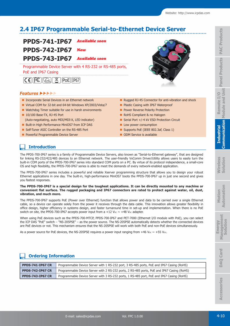
PAC Products
4-10E-mail: [email protected] Vol. FPC 1.0.00
Website: http://www.icpdas.com
PA
C P
rodu
cts
Pan
el P
rodu
cts
Rem
ote
I/O
M
odul
e an
d U
nit
DA
Q C
ard
Indu
stri
al
Com
mun
icat
ion
Wir
eles
s So
luti
onM
otio
n
Au
tom
atio
nA
cces
sori
esEn
ergy
M
anag
emen
tSo
luti
on
PPDS-741-IP67 PPDS-742-IP67PPDS-743-IP67Programmable Device Server with 4 RS-232 or RS-485 ports, PoE and IP67 Casing
The PPDS-700-IP67 series is a family of Programmable Device Servers, also known as "Serial-to-Ethernet gateway", that are designed for linking RS-232/422/485 devices to an Ethernet network. The user-friendly VxComm Driver/Utility allows users to easily turn the built-in COM ports of the PPDS-700-IP67 series into standard COM ports on a PC. By virtue of its protocol independence, a small-core OS and high fl exibility, the PPDS-700-IP67 series is able to meet the demands of every network-enabled application.
The PPDS-700-IP67 series includes a powerful and reliable Xserver programming structure that allows you to design your robust Ethernet applications in one day. The built-in, high-performance MiniOS7 boots the PPDS-700-IP67 up in just one second and gives you fastest responses.
The PPDS-700-IP67 is a special design for the toughest applications. It can be directly mounted to any machine or convenient flat surface. The rugged packaging and IP67 connectors are rated to protect against water, oil, dust, vibration, and much more.
The PPDS-700-IP67 supports PoE (Power over Ethernet) function that allows power and data to be carried over a single Ethernet cable, so a device can operate solely from the power it receives through the data cable. This innovation allows greater fl exibility in offi ce design, higher effi ciency in systems design, and faster turnaround time in set-up and implementation. When there is no PoE switch on site, the PPDS-700-IP67 accepts power input from a +12 VDC ~ +48 VDC adapter.
When using PoE devices such as the PPDS-700-MTCP, PPDS-700-IP67 and PET-7000 (Ethernet I/O module with PoE), you can select the ICP DAS "PoE" switch – "NS-205PSE" – as the power source. The NS-205PSE automatically detects whether the connected devices are PoE devices or not. This mechanism ensures that the NS-205PSE will work with both PoE and non-PoE devices simultaneously.
As a power source for PoE devices, the NS-205PSE requires a power input ranging from +46 VDC ~ +55 VDC.
Available soonAvailable soon
NewNew
Available soonAvailable soon
PPDS-741-IP67 CR Programmable Device Server with 1 RS-232 port, 3 RS-485 ports, PoE and IP67 Casing (RoHS)
PPDS-742-IP67 CR Programmable Device Server with 2 RS-232 ports, 2 RS-485 ports, PoE and IP67 Casing (RoHS)
PPDS-743-IP67 CR Programmable Device Server with 3 RS-232 ports, 1 RS-485 port, PoE and IP67 Casing (RoHS)
Incorporate Serial Devices in an Ethernet network Rugged RJ-45 Connector for anti-vibration and shock
Virtual COM for 32-bit and 64-bit Windows XP/2003/Vista/7 Plastic Casing with IP67 Waterproof
Watchdog Timer suitable for use in harsh environments Power Reverse Polarity Protection
10/100 Base-TX, RJ-45 Port RoHS Compliant & no Halogen
(Auto-negotiating, auto MDI/MDI-X, LED indicator) Serial Port +/-4 kV ESD Protection Circuit
Built-in High Performance MiniOS7 from ICP DAS Low power consumption
Self-Tuner ASIC Controller on the RS-485 Port Supports PoE (IEEE 802.3af, Class 1)
Powerful Programmable Device Server ODM Service is available
Features
2.4 IP67 Programmable Serial-to-Ethernet Device Server
Ordering Information
Introduction
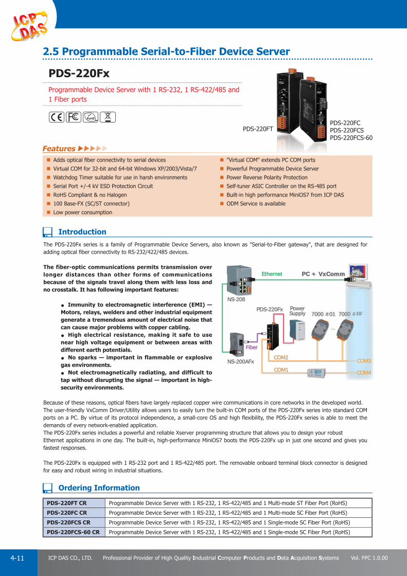
PAC Products
4-11 ICP DAS CO., LTD. Professional Provider of High Quality Industrial Computer Products and Data Acquisition Systems Vol. FPC 1.0.00
PDS-220FxProgrammable Device Server with 1 RS-232, 1 RS-422/485 and 1 Fiber ports
The PDS-220Fx series is a family of Programmable Device Servers, also known as "Serial-to-Fiber gateway", that are designed for adding optical fi ber connectivity to RS-232/422/485 devices.
The fiber-optic communications permits transmission over longer distances than other forms of communications because of the signals travel along them with less loss and no crosstalk. It has following important features:
• Immunity to electromagnetic interference (EMI) — Motors, relays, welders and other industrial equipment generate a tremendous amount of electrical noise that can cause major problems with copper cabling.• High electrical resistance, making it safe to use near high voltage equipment or between areas with different earth potentials. • No sparks — important in flammable or explosive gas environments. • Not electromagnetically radiating, and difficult to tap without disrupting the signal — important in high-security environments.
Because of these reasons, optical fi bers have largely replaced copper wire communications in core networks in the developed world.The user-friendly VxComm Driver/Utility allows users to easily turn the built-in COM ports of the PDS-220Fx series into standard COM ports on a PC. By virtue of its protocol independence, a small-core OS and high fl exibility, the PDS-220Fx series is able to meet the demands of every network-enabled application.The PDS-220Fx series includes a powerful and reliable Xserver programming structure that allows you to design your robustEthernet applications in one day. The built-in, high-performance MiniOS7 boots the PDS-220Fx up in just one second and gives you fastest responses.
The PDS-220Fx is equipped with 1 RS-232 port and 1 RS-422/485 port. The removable onboard terminal block connector is designed for easy and robust wiring in industrial situations.
NS-208
Ethernet PC + VxComm
COM3
COM4
NS-200AFx
PDS-220Fx PowerSupply 7000 #01 7000 #FF
Fiber
COM1
COM2
...
PDS-220FTPDS-220FCPDS-220FCSPDS-220FCS-60
PDS-220FT CR Programmable Device Server with 1 RS-232, 1 RS-422/485 and 1 Multi-mode ST Fiber Port (RoHS)
PDS-220FC CR Programmable Device Server with 1 RS-232, 1 RS-422/485 and 1 Multi-mode SC Fiber Port (RoHS)
PDS-220FCS CR Programmable Device Server with 1 RS-232, 1 RS-422/485 and 1 Single-mode SC Fiber Port (RoHS)
PDS-220FCS-60 CR Programmable Device Server with 1 RS-232, 1 RS-422/485 and 1 Single-mode SC Fiber Port (RoHS)
PDS-220FCPDS-220FCPDS-220FC
Features Adds optical fi ber connectivity to serial devices "Virtual COM" extends PC COM ports
Virtual COM for 32-bit and 64-bit Windows XP/2003/Vista/7 Powerful Programmable Device Server
Watchdog Timer suitable for use in harsh environments Power Reverse Polarity Protection
Serial Port +/-4 kV ESD Protection Circuit Self-tuner ASIC Controller on the RS-485 port
RoHS Compliant & no Halogen Built-in high performance MiniOS7 from ICP DAS
100 Base-FX (SC/ST connector) ODM Service is available
Low power consumption
2.5 Programmable Serial-to-Fiber Device Server
Ordering Information
Introduction

PAC Products
4-12E-mail: [email protected] Vol. FPC 1.0.00
Website: http://www.icpdas.com
PA
C P
rodu
cts
Pan
el P
rodu
cts
Rem
ote
I/O
M
odul
e an
d U
nit
DA
Q C
ard
Indu
stri
al
Com
mun
icat
ion
Wir
eles
s So
luti
onM
otio
n
Au
tom
atio
nA
cces
sori
esEn
ergy
M
anag
emen
tSo
luti
on
The tDS-700 is a series of Serial-to-Ethernet device servers designed to add Ethernet and Internet connectivity to any RS-232 and RS-422/485 device, and to eliminate the cable length limitation of legacy serial communication. By using the VxComm Driver/Utility, the built-in COM port of the tDS-700 series can be virtualized to a standard PC COM port in Windows. Therefore, users can transparently access or monitor serial devices over the Internet/Ethernet without software modifi cation.
tDS-700 seriestDS-712
tDS-700 SeriestDS-712 CR Tiny Device Server with PoE and 1 RS-232 Port (RoHS)tDS-715i CR NewNew Tiny Device Server with PoE and 1 Isolated RS-422/485 Port (RoHS)tDS-722 CR Tiny Device Server with PoE and 2 RS-232 Ports (RoHS)tDS-732 CR Tiny Device Server with PoE and 3 RS-232 Ports (RoHS)tDS-715 CR Tiny Device Server with PoE and 1 RS-422/485 Port (RoHS)tDS-725 CR Tiny Device Server with PoE and 2 RS-485 Ports (RoHS)tDS-735 CR Tiny Device Server with PoE and 3 RS-485 Ports (RoHS)tDS-718 CR Tiny Device Server with PoE and 1 RS-232/422/485 Port (RoHS)tDS-724 CR Tiny Device Server with PoE, 1 RS-485 and 1 RS-232 Ports (RoHS)tDS-734 CR Tiny Device Server with PoE, 1 RS-485 and 2 RS-232 Ports (RoHS)Includes: One CA-002 cable.
Incorporates any RS-232/422/485 serial device in Ethernet 10/100 Base-TX Ethernet, RJ-45 x 1 (Auto-negotiating, Contains a 32-bit MCU that effi ciently handles network traffi c auto MDI/MDIX, LED Indicators)Operation Modes: Virtual COM, TCP Server, TCP Client Redundant power inputs: PoE (IEEE 802.3af, Class 1) andVirtual COM for 32/64-bit Windows XP/2003/2012/Vista/7/8 DC jackData Packing Modes: Length, Delimiter, timeout, Char-timeout Allows automatic RS-485 direction controlSupports pair-connection (serial-bridge, serial-tunnel) applications Male DB-9 or terminal block connector for easy wiringSupports UDP responder for device discovery (UDP Search) Tiny form-factor and low power consumptionStatic IP or DHCP network confi guration RoHS compliant & no HalogenEasy fi rmware update via the Ethernet (BOOTP, TFTP) Cost-effective device serversTiny Web server for serial and network confi guration (HTTP)
Features
2.6 Tiny Serial-to-Ethernet Device Server & Modbus Gateway
tDS-700 SeriesTiny Serial-to-Ethernet Device Server
Ordering Information
Introduction

PAC Products
4-13 ICP DAS CO., LTD. Professional Provider of High Quality Industrial Computer Products and Data Acquisition Systems Vol. FPC 1.0.00
tGW-700 seriestGW-712
The tGW-700 module is a Modbus gateway that enables a Modbus TCP/UDP host to communicate with serial Modbus RTU/ASCII devices through an Ethernet network, and eliminates the cable length limitation of legacy serial communication devices. The module can be used to create a pair-connection application, and can then route data over TCP/IP between two serial Modbus RTU/ASCII devices, which is useful when connecting mainframe computers, servers or other serial devices that use Modbus RTU/ASCII protocols and do not themselves have Ethernet capability.
tGW-700 SeriestGW-712 CR Tiny Modbus/TCP to RTU/ASCII Gateway with PoE and 1 RS-232 Port (RoHS)
tGW-715i CR NewNew Tiny Modbus/TCP to RTU/ASCII Gateway with PoE and 1 Isolated RS-422/485 Port (RoHS)
tGW-722 CR Tiny Modbus/TCP to RTU/ASCII Gateway with PoE and 2 RS-232 Ports (RoHS)
tGW-732 CR Tiny Modbus/TCP to RTU/ASCII Gateway with PoE and 3 RS-232 Ports (RoHS)
tGW-715 CR Tiny Modbus/TCP to RTU/ASCII Gateway with PoE and 1 RS-422/485 (RoHS)
tGW-725 CR Tiny Modbus/TCP to RTU/ASCII Gateway with PoE and 2 RS-485 Ports (RoHS)
tGW-735 CR Tiny Modbus/TCP to RTU/ASCII Gateway with PoE and 3 RS-485 Ports (RoHS)
tGW-718 CR Tiny Modbus/TCP to RTU/ASCII Gateway with PoE and 1 RS-232/422/485 Port (RoHS)
tGW-724 CR Tiny Modbus/TCP to RTU/ASCII Gateway with PoE, 1 RS-485 and 1 RS-232 Ports (RoHS)
tGW-734 CR Tiny Modbus/TCP to RTU/ASCII Gateway with PoE, 1 RS-485 and 2 RS-232 Ports (RoHS)
Includes: One CA-002 cable.
Supports Modbus TCP/UDP master and slave 10/100 Base-TX Ethernet, RJ-45 x 1 (Auto-negotiating, Supports Modbus RTU/ASCII master and slave auto MDI/MDIX, LED Indicators)Max. TCP connections (masters) per serial port: 32 (tGW-71x), Includes redundant power inputs: PoE (IEEE 802.3af, 16 (tGW-72x) or 10 (tGW-73x) Class 1) and DC jackRead-cache ensures faster Modbus TCP/UDP response Allows automatic RS-485 direction controlSupports UDP responder for device discovery (UDP Search) Male DB-9 or terminal block connector for easy wiringStatic IP or DHCP network confi guration Tiny form-factor and low power consumptionEasy fi rmware update via the Ethernet (BOOTP, TFTP) RoHS compliant & no HalogenTiny Web server for serial and network confi guration (HTTP) Cost-effective Modbus GatewayContains a 32-bit MCU that effi ciently handles network traffi c
Features
tGW-700 SeriesTiny Modbus/TCP to RTU/ASCII Gateway
Ordering Information
Introduction

PAC Products
4-14E-mail: [email protected] Vol. FPC 1.0.00
Website: http://www.icpdas.com
PA
C P
rodu
cts
Pan
el P
rodu
cts
Rem
ote
I/O
M
odul
e an
d U
nit
DA
Q C
ard
Indu
stri
al
Com
mun
icat
ion
Wir
eles
s So
luti
onM
otio
n
Au
tom
atio
nA
cces
sori
esEn
ergy
M
anag
emen
tSo
luti
on
tSH-700 series
Supports baud rate conversion application Supports Modbus RTU/ASCII protocol conversionSupports two masters sharing one slave port Raw data mode for most query-response protocolsRead-cache ensures faster response Built-in web server for easy confi guration (HTTP)Redundant power inputs: PoE and DC jack Allows automatic RS-485 direction controlTiny form-factor and low power consumption
Features
tSH-700 SeriesTiny Serial Port Sharer
Ordering Information
Introduction
NEWNEW
Serial Port Sharer: Includes one CA-002 cable.tSH-722 CR NewNew Tiny Serial Port Sharer with PoE and 2 RS-232 Ports (RoHS)
tSH-732 CR NewNew Tiny Serial Port Sharer with PoE and 3 RS-232 Ports (RoHS)
tSH-725 CR NewNew Tiny Serial Port Sharer with PoE and 2 RS-485 Ports (RoHS)
tSH-735 CR NewNew Tiny Serial Port Sharer with PoE and 3 RS-485 Ports (RoHS)
tSH-724 CR NewNew Tiny Serial Port Sharer with PoE, 1 RS-485 and 1 RS-232 Ports (RoHS)
tSH-734 CR NewNew Tiny Serial Port Sharer with PoE, 1 RS-485 and 2 RS-232 Ports (RoHS)
• Two Masters Share One Slave:This function allows two master devices connected to different serial ports to share slave devices. The queries from the masters are queued in the tSH-700 module and then processed one-by-one. Modbus mode can be used to convert the Modbus RTU/ASCII protocols, while raw data mode can be used for DCON or other query-response protocols. Different baud rates and data formats can also be used on the different serial ports.
• Read-Cache Function:The built-in read-cache function is used to store previous requests and responses of the Modbus messages in the memory buffer of the tSH-700 module. When other HMI/SCADA master controllers requiring the same information from the same salve RTU device, the cached response is returned immediately. This feature dramatically reduces the loading on the slave serial port communication, ensures faster responses to the master, and improves the stability of the entire system.
• Baud Rate Conversion: This function allows a single master device to communicate with slave devices using different baud rates and data formats. Most query-response protocols (half-duplex), e.g. DCON, are supported in the raw data mode. Full-duplex communication should also work when the data size is smaller than the built-in 512 bytes buffer on each serial port.
• Modbus RTU/ASCII Conversion: This function allows a single Modbus RTU/ASCII master device to communicate with Modbus RTU/ASCII slave devices using different protocols, baud rates and data formats.
RS-232/RS-485RS-232/RS-485RS-232/RS-485RS-232/RS-485
115200, E719600, N81
RS-232/RS-485RS-232/RS-485 RS-232/RS-485RS-232/RS-485
Modbus ASCIIModbus ASCII Modbus RTUModbus RTU
DCON Protocol(Raw Data Mode)DCON Protocol(Raw Data Mode)
RS-232/RS-485
RS-232/RS-485
DCON Protocol(Raw Data Mode)DCON Protocol(Raw Data Mode)
9600 bps
RS-232/RS-485
RS-232/RS-485
DCON Protocol(Raw Data Mode)DCON Protocol(Raw Data Mode)
115200 bps
Serial115200 bps
Serial
Raw data communication
RS-232/RS-485
RS-232/RS-485
Modbus RTUModbus RTU
RS-232/RS-485
RS-232/RS-485
RS-232/RS-485
RS-232/RS-485
Modbus ASCIIModbus ASCII
Modbus RTUModbus RTU
9600 bps
115200 bps
57600 bps
Protocol conversion
The tSH-700 module provides a number of functions, including "Baud Rate Conversion", "Modbus RTU/ASCII Conversion" and "Two Masters Share One Slave". The built-in web server provides easy confi guration interface, and no console commands are required.
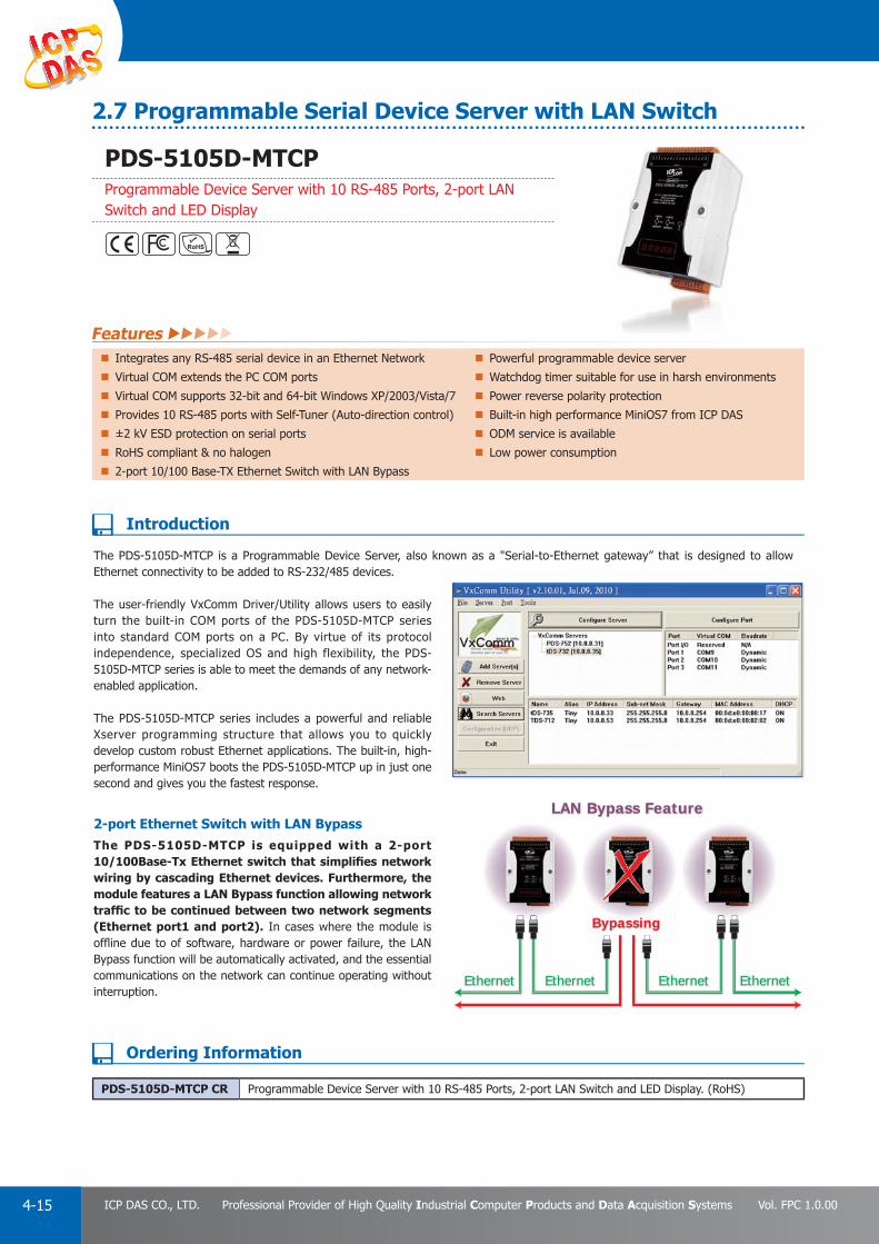
PAC Products
4-15 ICP DAS CO., LTD. Professional Provider of High Quality Industrial Computer Products and Data Acquisition Systems Vol. FPC 1.0.00
The PDS-5105D-MTCP is a Programmable Device Server, also known as a "Serial-to-Ethernet gateway” that is designed to allow Ethernet connectivity to be added to RS-232/485 devices.
The user-friendly VxComm Driver/Utility allows users to easily turn the built-in COM ports of the PDS-5105D-MTCP series into standard COM ports on a PC. By virtue of its protocol independence, specialized OS and high flexibility, the PDS-5105D-MTCP series is able to meet the demands of any network-enabled application.
The PDS-5105D-MTCP series includes a powerful and reliable Xserver programming structure that allows you to quickly develop custom robust Ethernet applications. The built-in, high-performance MiniOS7 boots the PDS-5105D-MTCP up in just one second and gives you the fastest response.
2-port Ethernet Switch with LAN BypassThe PDS-5105D-MTCP is equipped with a 2-port 10/100Base-Tx Ethernet switch that simplifi es network wiring by cascading Ethernet devices. Furthermore, the module features a LAN Bypass function allowing network traffi c to be continued between two network segments (Ethernet port1 and port2). In cases where the module is offl ine due to of software, hardware or power failure, the LAN Bypass function will be automatically activated, and the essential communications on the network can continue operating without interruption.
Ethernet Ethernet Ethernet
Bypassing ii
LAN Bypass Feature
Ethernet
PDS-5105D-MTCP CR Programmable Device Server with 10 RS-485 Ports, 2-port LAN Switch and LED Display. (RoHS)
Integrates any RS-485 serial device in an Ethernet Network Powerful programmable device server
Virtual COM extends the PC COM ports Watchdog timer suitable for use in harsh environments
Virtual COM supports 32-bit and 64-bit Windows XP/2003/Vista/7 Power reverse polarity protection
Provides 10 RS-485 ports with Self-Tuner (Auto-direction control) Built-in high performance MiniOS7 from ICP DAS
±2 kV ESD protection on serial ports ODM service is available
RoHS compliant & no halogen Low power consumption
2-port 10/100 Base-TX Ethernet Switch with LAN Bypass
Features
2.7 Programmable Serial Device Server with LAN Switch
PDS-5105D-MTCPProgrammable Device Server with 10 RS-485 Ports, 2-port LAN Switch and LED Display
Ordering Information
Introduction

PAC Products
4-16E-mail: [email protected] Vol. FPC 1.0.00
Website: http://www.icpdas.com
PA
C P
rodu
cts
Pan
el P
rodu
cts
Rem
ote
I/O
M
odul
e an
d U
nit
DA
Q C
ard
Indu
stri
al
Com
mun
icat
ion
Wir
eles
s So
luti
onM
otio
n
Au
tom
atio
nA
cces
sori
esEn
ergy
M
anag
emen
tSo
luti
on
The Modbus communications protocol has become the de facto industry standard, and is now the most commonly available means of connecting industrial electronic devices.
Modbus allows for communication between many devices connected to the same network, for example a system that measures temperature and humidity and communicates the results to a computer. Modbus is often used to connect a supervisory computer with a remote terminal unit (RTU) in supervisory control and data acquisition (SCADA) systems.
The μPAC-7186EX(D)-MTCP uses a default firmware to become a single Modbus/TCP to multiple Modbus/RTU converter. You can simply use the Modbus Utility to confi gure the device and then set the connection between the SCADA or HMI software and the μPAC-7186EX(D)-MTCP.
The μPAC-7186EX(D)-MTCP can also link to legacy serial devices that don't support Modbus/RTU. To use this function, you need to install the VxComm driver on the host PCs and create virtual COM ports for the remote serial ports on the μPAC-7186EX(D)-MTCP. You can then directly access the remote serial devices via the virtual COM ports.
Using the Modbus SDK, users can develop their own custom Modbus fi rmware, allowing extra functions and integration of serial devices. In this way, the μPAC-7186EX(D)-MTCP becomes a powerful controller.
The μPAC-7186EX(D)-MTCP contains a built-in operating system, the MiniOS7, which offers a stable and high performance environment that is similar to DOS. The MiniOS7 can boot up the μPAC-7186EX(D)-MTCP within just one second, with the added benefit of no virus problems and a small footprint. Furthermore, the μPAC-7186EX(D)-MTCP is designed for low power consumption, maintenance elimination (no hard disk and no fan), and is constructed from fi re-retardant materials (UL94-V0 level) with a robust case.
I/O Expansion Bus and Expansion BoardThe μPAC-7186EX(D)-MTCP supports a single I/O expansion bus for plugging with a X-board. ICP DAS provides many optional X-boards for the μPAC-7186EX(D)-MTCP, which offers various I/O functions, such as D/I, D/O, A/D, D/A, Timer/Counter, UART, fl ash memory, battery backup SRAM and AsicKey... etc.
Palm-sizedPower-Saving
Changeable
μPAC-7186EX-MTCP μPAC-7186EXD-MTCP
μPAC-7186EX-MTCP CR μPAC-7186EX with Default Modbus/TCP Firmware (RoHS)
μPAC-7186EXD-MTCP CR μPAC-7186EXD with Default Modbus/TCP Firmware (RoHS)
Incorporate Serial Devices in an Ethernet network Virtual COM for 32-bit and 64-bit Windows XP/2003/Vista/7
Supports Modbus/TCP and Modbus/RTU Programmable Internet/Ethernet Controller
"Virtual COM" extends PC COM ports Watchdog Timer suitable for use in harsh environments
10/100 Base-TX (Auto-negotiating, auto MDI/MDI-X, LED indicator) Power Reverse Polarity Protection Circuit
Self-Tuner ASIC Controller on the RS-485 Port RS-485 Port ESD Protection Circuit
5-digit LED Display (for versions with a display) RoHS Compliant & no Halogen
Built-in High Performance MiniOS7 from ICP DAS Low power consumption
Features
2.8 Programmable Modbus to Ethernet Gateway
μPAC-7186EX(D)-MTCPModbus/RTU to Modbus/TCP Gateway
Ordering Information
Introduction

PAC Products
4-17 ICP DAS CO., LTD. Professional Provider of High Quality Industrial Computer Products and Data Acquisition Systems Vol. FPC 1.0.00
MDC-700 series is a Modbus Data Concentrator that has ability to perform up to 200 Modbus/RTU commands to read/write from/to Modbus slave devices via RS-232/485 and allows up to 8 Modbus/TCP masters to get the polled data via the Ethernet.
MDC-700 series provide a built-in web server to ease the confi guring and provide clear information for the performed results of each Modbus/RTU command on the RS-232/485.
Modbus Data ConcentratorThe MDC performs the pre-defi ned Modbus/RTU commands to read/write data from/to the Modbus/RTU slave devices via the RS-232/485. It mirrors the data of the slave devices to its own shared memory. And it accepts up to 8 Modbus/TCP masters to directly read/write data form/to the shared memory instead of polling each Modbus/RTU slave device one by one.
This way not only makes the data on the RS-232/485 sharable to multiple Modbus/TCP master but also shorten the time to read/write data from/to multiple Modbus/RTU slave devices.
Great Capability of Shared MemoryThe MDC can perform up to 200 polling defi nitions. And the internal shared memory has four tables to store the polled AI, AO, DI and DO data. Each table can store up to 4000 registers.
Confi g.CSV to Ease Hard Work of Editing a lot of Defi nitionThe Modbus polling definition is defined in a Config.CSV fi le. Editing/checking a lot of polling defi nitions is a hard work and may have chance to make a mistake. A CSV format fi le can ease the work by using Excel. Furthermore, the built-in web server allows users import/export the Confi g.CSV via a simple mouse-click action.
Web Sever to Ease the Operating and Show Clear Information
The IP address, configuration file, Config.CSV can be simply configured via the Web server. And the performed results of all Modbus polling definition are shown on the web page. It is very easy to debug which Modbus/RTU device has communication problem. And the MDC fi rmware will skip the abnormal Modbus polling definition for a while to smoothly perform the whole polling without distribution.
MDC-711 MDC-714
Modbus Data Concentrator Confi g.CSV to Ease Hard Work of Editing a lot of Defi nition
Great Capability of Shared Memory Web Sever to Ease the Operating and Show Clear Information
Features
2.9 Modbus Data Concentrator, MDC-700 series
MDC-711Modbus data concentrator with 1x Ethernet and 1 x RS-232, 1 x RS-485
MDC-714Modbus data concentrator with 1x Ethernet and 1 x RS-232, 4 x RS-485
Introduction
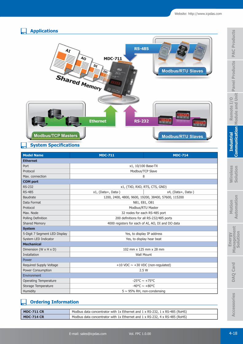
PAC Products
4-18E-mail: [email protected] Vol. FPC 1.0.00
Website: http://www.icpdas.com
PA
C P
rodu
cts
Pan
el P
rodu
cts
Rem
ote
I/O
M
odul
e an
d U
nit
DA
Q C
ard
Indu
stri
al
Com
mun
icat
ion
Wir
eles
s So
luti
onM
otio
n
Au
tom
atio
nA
cces
sori
esEn
ergy
M
anag
emen
tSo
luti
on
System Specifi cations
Applications
Model Name MDC-711 MDC-714
Ethernet
Port x1, 10/100 Base-TX
Protocol Modbus/TCP Slave
Max. connection 8
COM port
RS-232 x1, (TXD, RXD, RTS, CTS, GND)
RS-485 x1, (Data+, Data-) x4, (Data+, Data-)
Baudrate 1200, 2400, 4800, 9600, 19200, 38400, 57600, 115200
Data Format N81, E81, O81
Protocol Modbus/RTU Master
Max. Node 32 nodes for each RS-485 port
Polling Defi nition 200 defi nitions for all RS-232/485 ports
Shared Memory 4000 registers for each of AI, AO, DI and DO data
System
5-Digit 7 Segment LED Display Yes, to display IP address
System LED Indicator Yes, to display hear beat
Mechanical
Dimension (W x H x D) 102 mm x 125 mm x 28 mm
Installation Wall Mount
Power
Required Supply Voltage +10 VDC ~ +30 VDC (non-regulated)
Power Consumption 2.5 W
Environment
Operating Temperature -25°C ~ +75°C
Storage Temperature -40°C ~ +80°C
Humidity 5 ~ 95% RH, non-condensing
MDC-711 CR Modbus data concentrator with 1x Ethernet and 1 x RS-232, 1 x RS-485 (RoHS)
MDC-714 CR Modbus data concentrator with 1x Ethernet and 1 x RS-232, 4 x RS-485 (RoHS)
Ordering Information

PAC Products
4-19 ICP DAS CO., LTD. Professional Provider of High Quality Industrial Computer Products and Data Acquisition Systems Vol. FPC 1.0.00
3. Converter/Repeater/Hub/Splitter"Self-Tuner"A conventional RS-232 to RS-485 converter uses the DIP switch to select the baud rate and data format for the whole RS-485 network. All modules, devices and equipments in the network should be confi gured to the same baud rate and data format. Unfortunately most real world applications can't be implemented in such a simple way. The Self-Tuner is an innovative chip designed to solve this problem. Every converter contains a Self-Tuner chip. The chip automatically tunes the baud rate and data format to the whole network. Therefore the I-7520 can connect to modules, devices and equipments with different baud rates and data formats in a network.
Furthermore, the RS-485 is a 2 Wire half-duplex network. To transmit and receive data via the twisted pair wire, a transmission direction control for the RS-485 is needed. In conventional designs, software has to switch a hardware handshaking signal such as RTS (Request To Send) to control the transmission direction. The Self-Tuner chip automatically detects and controls the direction of the transmission of the RS-485 network. So the application program does not have to care about the direction control.
High Quality Isolated RS-485 Repeater/Hub/SplitterThe maximum effective distance of RS-485 without repeater is 1200 meters (4000 feet) at baud rates up to 9.6 Kbps and up to 32 (256) nodes can be connected. With the professional design, the repeater I-7510 solves the problem of signal weakening and extends the maximum effective distance by 1200 m and connects 32 (256) nodes more. And it has optical isolation design for lightning and surge protection. If the RS-485 topology is too complex to make the communicating well, a RS-485 hub or splitter is recommended.
I-7520U4 and I-7514U are multichannel RS-485 repeater/hub/splitter. Each channel is independent and has optical isolation, short circuit and open circuit protection. Thus when one channel fails, it will not affect another channel of the hub. The features make it perfect to star type or mixed type topology in complex and large scale RS-485 network.
Self-Tuner Chip
I-7520U4 I-7514U
I-7520
ICP DAS Self-Tuner ASIC Features:• Multiple Baud Rate
• Multiple Data Format
• Automatic RS-485 Direction Control
yp yp p gy p g
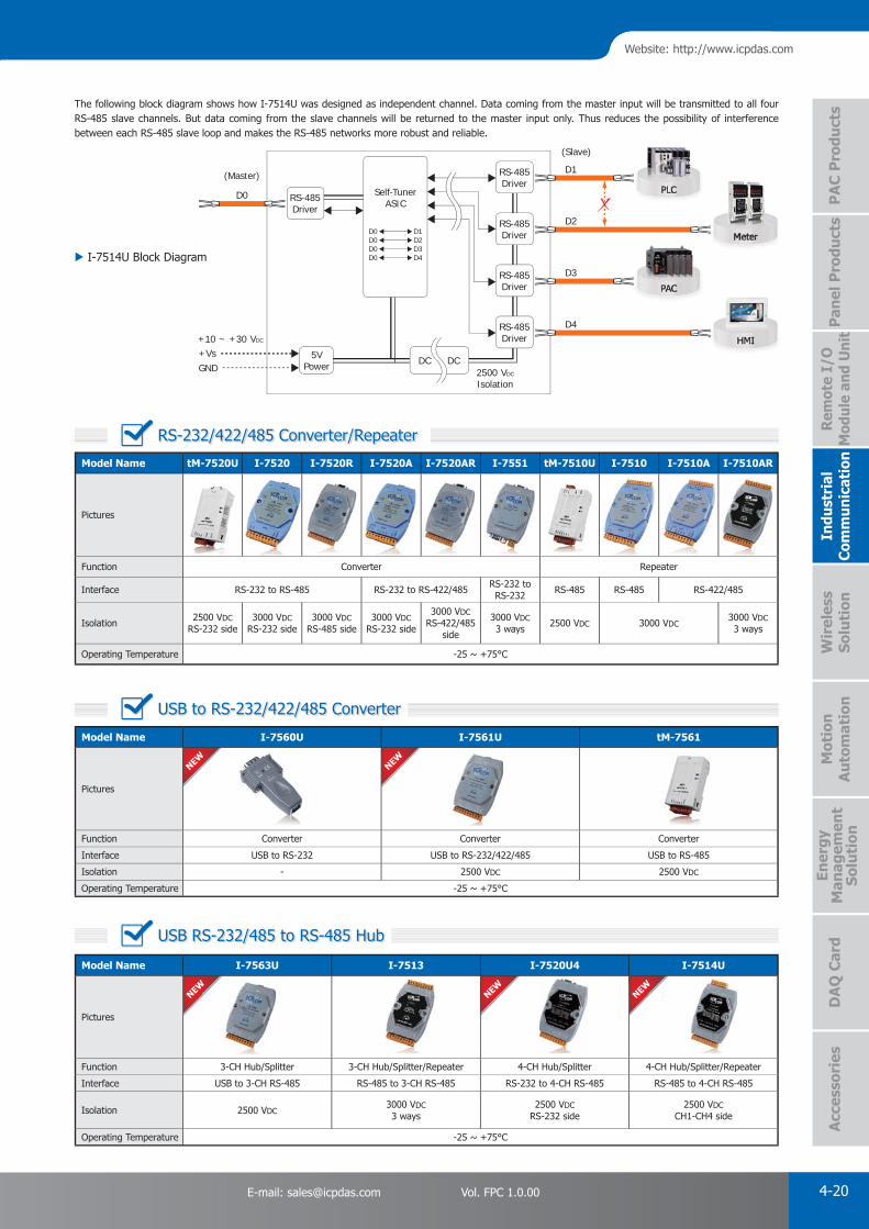
PAC Products
4-20E-mail: [email protected] Vol. FPC 1.0.00
Website: http://www.icpdas.com
PA
C P
rodu
cts
Pan
el P
rodu
cts
Rem
ote
I/O
M
odul
e an
d U
nit
DA
Q C
ard
Indu
stri
al
Com
mun
icat
ion
Wir
eles
s So
luti
onM
otio
n
Au
tom
atio
nA
cces
sori
esEn
ergy
M
anag
emen
tSo
luti
on
NEWNEW NEW
NEWNEW
Model Name I-7563U I-7513 I-7520U4 I-7514U
Pictures
Function 3-CH Hub/Splitter 3-CH Hub/Splitter/Repeater 4-CH Hub/Splitter 4-CH Hub/Splitter/Repeater
Interface USB to 3-CH RS-485 RS-485 to 3-CH RS-485 RS-232 to 4-CH RS-485 RS-485 to 4-CH RS-485
Isolation 2500 VDC3000 VDC3 ways
2500 VDCRS-232 side
2500 VDCCH1-CH4 side
Operating Temperature -25 ~ +75°C
Model Name I-7560U I-7561U tM-7561
Pictures
Function Converter Converter Converter
Interface USB to RS-232 USB to RS-232/422/485 USB to RS-485
Isolation - 2500 VDC 2500 VDC
Operating Temperature -25 ~ +75°C
Model Name tM-7520U I-7520 I-7520R I-7520A I-7520AR I-7551 tM-7510U I-7510 I-7510A I-7510AR
Pictures
Function Converter Repeater
Interface RS-232 to RS-485 RS-232 to RS-422/485 RS-232 to RS-232 RS-485 RS-485 RS-422/485
Isolation 2500 VDCRS-232 side
3000 VDCRS-232 side
3000 VDCRS-485 side
3000 VDCRS-232 side
3000 VDCRS-422/485
side
3000 VDC3 ways 2500 VDC 3000 VDC
3000 VDC3 ways
Operating Temperature -25 ~ +75°C
The following block diagram shows how I-7514U was designed as independent channel. Data coming from the master input will be transmitted to all four RS-485 slave channels. But data coming from the slave channels will be returned to the master input only. Thus reduces the possibility of interference between each RS-485 slave loop and makes the RS-485 networks more robust and reliable.
RS-232/422/485 Converter/Repeater
USB to RS-232/422/485 Converter
USB RS-232/485 to RS-485 Hub
2500 VDC
Isolation
Self-TunerASIC
+10 ~ +30 VDC
+VsGND
5VPower DC DC
RS-485Driver
D1
D3RS-485Driver
D4RS-485Driver
D2RS-485Driver
RS-485Driver
D0
D0 D1D0 D2D0 D3D0 D4
(Master)
(Slave)
I-7514U Block Diagram
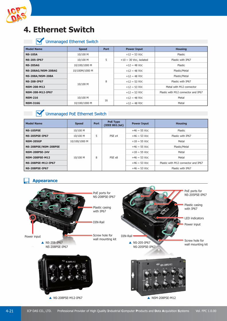
PAC Products
4-21 ICP DAS CO., LTD. Professional Provider of High Quality Industrial Computer Products and Data Acquisition Systems Vol. FPC 1.0.00
4. Ethernet Switch
Model Name Speed Port Power Input Housing
NS-105A 10/100 M
5
+12 ~ 53 VDC Plastic
NS-205-IP67 10/100 M +10 ~ 30 VDC, isolated Plastic with IP67
NS-205AG 10/100/1000 M +12 ~ 48 VDC Plastic
NS-208AG/NSM-208AG 10/100M/1000 M
8
+12 ~ 48 VDC Plastic/Metal
NS-208A/NSM-208A
10/100 M
+12 ~ 48 VDC Plastic/Metal
NS-208-IP67 +12 ~ 53 VDC Plastic with IP67
NSM-208-M12 +12 ~ 53 VDC Metal with M12 connector
NSM-208-M12-IP67 +12 ~ 53 VDC Plastic with M12 connector and IP67
NSM-216 10/100 M16
+12 ~ 48 VDC Metal
NSM-316G 10/100/1000 M +12 ~ 48 VDC Metal
Model Name Speed PortPoE Type
(IEEE 802.3at)Power Input Housing
NS-105PSE 10/100 M
5 PSE x4
+46 ~ 55 VDC Plastic
NS-205PSE-IP67 10/100 M +46 ~ 53 VDC Plastic with IP67
NSM-205GP 10/100/1000 M +18 ~ 55 VDC Metal
NS-208PSE/NSM-208PSE
10/100 M 8 PSE x8
+46 ~ 55 VDC Plastic/Metal
NSM-208PSE-24V +18 ~ 55 VDC Metal
NSM-208PSE-M12 +46 ~ 53 VDC Metal
NS-208PSE-M12-IP67 +46 ~ 53 VDC Plastic with M12 connector and IP67
NS-208PSE-IP67 +46 ~ 53 VDC Plastic with IP67
DIN-RailScrew hole forwall mounting kit
Power input
LED indicators
Plastic casingwith IP67
PoE ports forNS-205PSE-IP67PoE ports for
NS-208PSE-IP67
Plastic casing with IP67
DIN-Rail
Screw hole forwall mounting kit
Power input
Appearance
NS-208-IP67NS-208PSE-IP67
NS-208PSE-M12-IP67 NSM-208PSE-M12
NS-205-IP67NS-205PSE-IP67
Unmanaged Ethernet Switch
Unmanaged PoE Ethernet Switch

PAC Products
4-22E-mail: [email protected] Vol. FPC 1.0.00
Website: http://www.icpdas.com
PA
C P
rodu
cts
Pan
el P
rodu
cts
Rem
ote
I/O
M
odul
e an
d U
nit
DA
Q C
ard
Indu
stri
al
Com
mun
icat
ion
Wir
eles
s So
luti
onM
otio
n
Au
tom
atio
nA
cces
sori
esEn
ergy
M
anag
emen
tSo
luti
on
Model Name Ethernet Fiber Port
Power Input HousingSpeed Port Speed Port
RS-405/RSM-405 10/100 Mbps 5 – – +10 ~ 30 VDC Plastic/Metal
RS-408/RSM-408 10/100 Mbps 8 – – +10 ~ 30 VDC Plastic/Metal
RS-405F/RSM-405F Series 10/100 Mbps 3 100 Mbps 2 +10 ~ 30 VDC Plastic/Metal
RSM-405-R 10/100 Mbps 5 – – +10 ~ 30 VDC Metal
The Real-time Redundant Ring Switch offers fault-tolerant industrial Ethernet with ring network topology. The built-in ICP DAS proprietary Cyber-Ring technology detects and recovers from a fi ber or copper link failure within approximately 20 ms – for the majority of applications a seamless process. Modbus/TCP, Modbus/RTU and OPC supported, SCADA application can monitor status of Ethernet and fi ber port with Modbus or OPC protocol. And, the relay output facility can deliver warning signal while dual power or network link fails.
20 ms (typical) to detect and recover from a Ethernet link failure. 3.2 Gbps high performance memory bandwidth
Automatic MDI / MDI-X crossover for plug-and-play 1 Mbit Frame buffer memory
Each port supports both 10/100 Mbps speed auto negotiation 1024/2048 MAC addresses
Store-and-forward architecture Supports operating temperatures from -40°C ~ +75°C
Full duplex IEEE 802.3x and half duplex backpressure fl ow control DIN-Rail mount for industrial use
Redundant Power Inputs with power failure alarm by relay out
Features
SCADADADACACAADAADCAASSSCSSC
Backup path
Modbus/RTU
RSM-405
RSM-405
RSM-405
RSM-405
Modbus/TCP
Real-time Redundant Ring Ethernet/Fiber Port Switch
Real-time Redundant Ring Switch
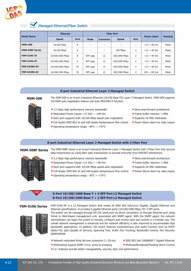
PAC Products
4-23 ICP DAS CO., LTD. Professional Provider of High Quality Industrial Computer Products and Data Acquisition Systems Vol. FPC 1.0.00
Model Name Ethernet Fiber Port
Power Input HousingSpeed Port Mode Connector Speed Port
MSM-508 10/100 Mbps 8 – – – – +12 ~ 48 VDC Metal
MSM-508F Series 10/100 Mbps 6 – – 100 Mbps 2 +12 ~ 48 VDC Metal
FSM-510G-2F 10/100/1000 Mbps 8 SFP cage LC 100/1000 Mbps 2 +12 ~ 48 VDC Metal
FSM-510G-4F 10/100/1000 Mbps 6 SFP cage LC 100/1000 Mbps 4 +12 ~ 48 VDC Metal
FSM-6228G-DC 10/100/1000 Mbps 24 SFP cage LC 100/1000 Mbps 4 +12 ~ 48 VDC Metal
FSM-6228G-AC 10/100/1000 Mbps 24 SFP cage LC 100/1000 Mbps 4 100 ~ 240 VAC Metal
Managed Ethernet/Fiber Switch
8-port Industrial Ethernet Layer 2 Managed Switch
8-port Industrial Ethernet Layer 2 Managed Switch with 2-Fiber Port
6-Port 10/100/1000 Base-T + 4 SFP Port L2 Managed Switch8-Port 10/100/1000 Base-T + 2 SFP Port L2 Managed Switch
The MSM-508 is an 8-port Industrial Ethernet (10/100 Base-TX) Layer 2 Managed Switch. MSM-508 supports 10/100M auto negotiation feature and auto MDI/MDI-X function.
The MSM-508F series is an 8-port Industrial Ethernet Layer 2 Managed Switch with 2-Fiber Port that secures data transmission by using fi ber optic transmission to provide immunity from EMI/RFI interference.
FSM-510G-4F is a L2 Managed Switch that meets all IEEE 802.3ab/u/x/z Gigabit, Gigabit Ethernet and Ethernet specifi cations. It provides 6 gigabit Ethernet ports (10/100/1000 Mbps TP) 4 SFP ports.The switch can be managed through RS-232 serial port via direct connection, or through Ethernet port using Telnet or Web-Based management unit, associated with SNMP agent. With the SNMP agent, the network administrator can logon the switch to monitor, confi gure and control each port activity in a friendly way. The overall network management is enhanced and the network effi ciency is also improved to accommodate high bandwidth applications. In addition, the switch features comprehensive and useful function such as DHCP Option 82, QoS (Quality of Service), Spanning Tree, VLAN, Port Trunking, Bandwidth Control, Port Security, SNMP/RMON
Store-and-forward architecture
Frame buffer memory: 1 Mbit
Supports 2K MAC Addresses
Power failure alarm by relay output
Store-and-forward architecture
Frame buffer memory: 1 Mbit
Supports 2K MAC Addresses
Power failure alarm by relay output
IEEE 802.3ab 1000BASE-T Gigabit Ethernet
Multicast/Broadcast/Flooding Storm Control
3.2 Gbps high performance memory bandwidth
Redundant Power Inputs +12 VDC ~ +48 VDC
Each port supports both 10/100 Mbps speed auto negotiation
Full duplex IEEE 802.3x and half duplex backpressure fl ow control
Operating temperature range: -40°C ~ +75°C
3.2 Gbps high performance memory bandwidth
Redundant Power Inputs +12 VDC ~ +48 VDC
Each port supports both 10/100 Mbps speed auto negotiation
Full duplex IEEE 802.3x and half duplex backpressure fl ow control
Operating temperature range: -30°C ~ +75°C
Network redundant Ring fail-over protection (< 20 ms)
Multicasting support IGMP v1/v2, proxy & snooping
L2+ features provide better manageability, security, QoS, and performance
MSM-508
MSM-508F Series
FSM-510G Series
NEW
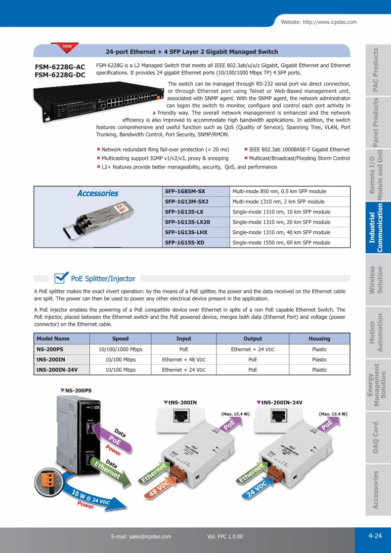
PAC Products
4-24E-mail: [email protected] Vol. FPC 1.0.00
Website: http://www.icpdas.com
PA
C P
rodu
cts
Pan
el P
rodu
cts
Rem
ote
I/O
M
odul
e an
d U
nit
DA
Q C
ard
Indu
stri
al
Com
mun
icat
ion
Wir
eles
s So
luti
onM
otio
n
Au
tom
atio
nA
cces
sori
esEn
ergy
M
anag
emen
tSo
luti
on
Accessories SFP-1G85M-SX Multi-mode 850 nm, 0.5 km SFP module
SFP-1G13M-SX2 Multi-mode 1310 nm, 2 km SFP module
SFP-1G13S-LX Single-mode 1310 nm, 10 km SFP module
SFP-1G13S-LX20 Single-mode 1310 nm, 20 km SFP module
SFP-1G13S-LHX Single-mode 1310 nm, 40 km SFP module
SFP-1G15S-XD Single-mode 1550 nm, 60 km SFP module
Accessorie
24-port Ethernet + 4 SFP Layer 2 Gigabit Managed Switch
FSM-6228G is a L2 Managed Switch that meets all IEEE 802.3ab/u/x/z Gigabit, Gigabit Ethernet and Ethernet specifi cations. It provides 24 gigabit Ethernet ports (10/100/1000 Mbps TP) 4 SFP ports.
The switch can be managed through RS-232 serial port via direct connection, or through Ethernet port using Telnet or Web-Based management unit, associated with SNMP agent. With the SNMP agent, the network administrator can logon the switch to monitor, configure and control each port activity in
a friendly way. The overall network management is enhanced and the network effi ciency is also improved to accommodate high bandwidth applications. In addition, the switch
features comprehensive and useful function such as QoS (Quality of Service), Spanning Tree, VLAN, Port Trunking, Bandwidth Control, Port Security, SNMP/RMON.
IEEE 802.3ab 1000BASE-T Gigabit Ethernet
Multicast/Broadcast/Flooding Storm Control
Network redundant Ring fail-over protection (< 20 ms)
Multicasting support IGMP v1/v2/v3, proxy & snooping
L2+ features provide better manageability, security, QoS, and performance
FSM-6228G-ACFSM-6228G-DC
NEW
a frieeffi ciency is also im
f h d
Model Name Speed Input Output Housing
NS-200PS 10/100/1000 Mbps PoE Ethernet + 24 VDC Plastic
tNS-200IN 10/100 Mbps Ethernet + 48 VDC PoE Plastic
tNS-200IN-24V 10/100 Mbps Ethernet + 24 VDC PoE Plastic
A PoE splitter makes the exact invert operation: by the means of a PoE splitter, the power and the data received on the Ethernet cable are split. The power can then be used to power any other electrical device present in the application.
A PoE injector enables the powering of a PoE compatible device over Ethernet in spite of a non PoE capable Ethernet Switch. The PoE injector, placed between the Ethernet switch and the PoE powered device, merges both data (Ethernet Port) and voltage (power connector) on the Ethernet cable.
PoE Splitter/Injector

PAC Products
4-25 ICP DAS CO., LTD. Professional Provider of High Quality Industrial Computer Products and Data Acquisition Systems Vol. FPC 1.0.00
A Media Converter is a simple and low-cost networking device which allows connect two dissimilar media types such as an Ethernet cable with fi ber optic, even though transmission speed are different. It is a perfect add-on to an Ethernet switch when combining copper and fi ber within the Ethernet Network. Multiple cabling types such as coax, twisted pair, multi-mode and single-mode fi ber optics are supported.
An unmanaged industrial Ethernet switch with fi ber port(s) provides both Ethernet switch functionality (up to 8 RJ45 ports) and media converter (up to 2 fi ber ports) for safe and fast local and long distance (max 60 km) transmissions. Each switch is plug and play, can be installed on DIN-Rail, and supports wide operating temperature range.
Model Name Fiber Port Ethernet
Operation temperature Power Input Housing
Speed Port Speed Port
NS-200F series 100 M 1 10/100 M 1 0 ~ +70°C +10 ~ 30 VDC Plastic
NS-200WDM 100 M 1 10/100 M 1 0 ~ +70°C +12 ~ 48 VDC Plastic
NS-200AF series 100 M 1 10/100 M 1 -30 ~ +75°C +12 ~ 48 VDC Plastic
NSM-200G-SFP
NSM-200SX/SX2/LX1000 M 1 10/100/1000 M 1 -30 ~ +75°C +12 ~ 48 VDC Metal
Model Name Fiber Port Ethernet
Power Input HousingSpeed Port Speed Port PSE
(IEEE 802.3af)
NS-205AF Series
NSM-205AF Series100 M 1 10/100 M 4 - +12 ~ 48 VDC Plastic/Metal
NS-205PF Series
NSM-205PF Series100 M 1 10/100 M 4 4 +12 ~ 48 VDC Plastic/Metal
NS-206AF Series
NSM-206AF Series100 M 1 10/100 M 4 - +12 ~ 48 VDC Plastic/Metal
NS-209F Series
NSM-209F Series100 M 1 10/100 M 8 - +12 ~ 48 VDC Plastic/Metal
nctionality (up to 8 RJ45 ports) and media converter (up for safe and fast local and long distance (max 60 km)ch switch is plug and play, can be installed on DIN-Rail, e operating temperature range.
Fiber Port Ethernet
NS-200WDM
NS-209FT
NSM-209FC NS-205AFC-T
NS-206AFT-T
NS-205PFT
NSM-209FT
NS-209FC
NS-200FCS
NS-200FT
NSM-200SXNSM-200G-SFP
NSM-200SX2
NSM-205PFC
NSM-206AFC-TNSM-206AFT-T
NSM-205AFT-T
Industrial Media Converters & WDM Media Converter
Unmanaged Ethernet Switch with Fiber Ports
NSNS-2200WDM
NS-200FCS
NSNSNSNSNSSSSNS-NS-SS-S-SS-NSSSS-S-NSNSSNSNSSSNS 202020020020000020000002002002002200200222220002200002222202200FT
NSMMSNSMNNNSMNSNSNSM 220-202 0SX NSM-20022-20202 0G0G-SFSFP
NSM-200SX2
M di C tMedia Converter

PAC Products
4-26E-mail: [email protected] Vol. FPC 1.0.00
Website: http://www.icpdas.com
PA
C P
rodu
cts
Pan
el P
rodu
cts
Rem
ote
I/O
M
odul
e an
d U
nit
DA
Q C
ard
Indu
stri
al
Com
mun
icat
ion
Wir
eles
s So
luti
onM
otio
n
Au
tom
atio
nA
cces
sori
esEn
ergy
M
anag
emen
tSo
luti
on
Fieldbus
EtherNet/IP PROFIBUS
CAN
De
viceN
et
CANopen
HART PROFIN
ET
BACnet/IP M-Bus J19395. Fieldbus Solution
● Selection Guide
Model Name Description
5.1 EtherNet/IP GatewaysGW-7472 Ethernet/IP Adapter to Modbus TCP/RTU Master Gateway
GW-7473 Modbus TCP/RTU Slave to EtherNet/IP Scanner Gateway
5.2 BACnet/IP GatewayGW-5492 BACnet/IP to Modbus RTU Gateway
GW-5493 BACnet/IP to Modbus TCP Gateway
5.3CAN Bus Repeater/Bridge/Switch
I-7531 Isolated CAN Bus Repeater
I-7532 Isolated Two-channel CAN Bus Bridge
I-2534 4-Port CAN Bus Switch
I-5534-M 4-Port CAN Bus Switch with Metal Casing
5.4USB to CAN Converter
I-7565 1-Port Cost Effective USB to CAN Converter
I-7565-H1 1-Port High Performance USB to CAN Converter
I-7565-H2 2-Port High Performance USB to CAN Converter
I-7565-CPM Intelligent USB to CANopen Converter
I-7565-DNM Intelligent USB to DeviceNet Converter
5.5
CAN to Fiber Converter/Bridge I-2532 CAN to Multi-mode Fiber Converter
I-2533 CAN to Multi-mode Bridge
I-2533CS CAN to Single-mode Fiber Bridge
I-2533CS-60 CAN to Single-mode Fiber Bridge
5.6
Ethernet/Wi-Fi to CAN Converter I-7540D-MTCP Modbus TCP to CAN Converter
I-7540D Ethernet to CAN Converter
I-7540D-WF Wi-Fi to CAN Converter
5.7
Uart to CAN converter I-7530-FT RS-232 to Fault-Tolerance CAN Converter
I-7530 RS-232 to CAN Converter
I-7530A RS-232/422/485 to CAN Converter
I-7530A-MR Modbus RTU to CAN Converter
5.8
CANopen Gateway I-7231D CANopen Slave to DCON Master Gateway
I-7232D CANopen Slave to Modbus RTU Master Gateway
GW-7433D Modbus TCP/RTU Slave to CANopen Master Gateway
5.9 DeviceNet Gateway
I-7241D DeviceNet Slave to DCON Master Gateway
I-7242D DeviceNet Slave to Modbus RTU Master Gateway
GW-7243D DeviceNet Slave to Modbus TCP/RTU Master Gateway
GW-7434D Modbus TCP/RTU Slave to DeviceNet Master Gateway
5.10 J1939 GatewayGW-7228 Modbus RTU Slave to J1939 Gateway
GW-7238D Modbus TCP/RTU Slave to J1939 Gateway
verter

PAC Products
4-27 ICP DAS CO., LTD. Professional Provider of High Quality Industrial Computer Products and Data Acquisition Systems Vol. FPC 1.0.00
Model Name Description
5.11PC-based CAN Bus Boards
PEX-CAN200i 2-Port PCI Express CAN Communication Board
PISO-CAN100U 1-Port Universal PCI CAN Communication Board
PISO-CAN200U 2-Port Universal PCI CAN Communication Board
PISO-CAN400U 4-Port Universal PCI CAN Communication Board
PISO-CAN800U 8-Port Universal PCI CAN Communication Board
PCM-CAN100 1-Port PCI-104 CAN Communication Module
PCM-CAN200 2-Port PCI-104 CAN Communication Module
PCM-CAN200P 2-Port PCI-104 + CAN Communication Module
PISO-CM100U 1-Port Universal PCI CAN Board with Built-in Programmable CPU
PCM-CM100 1-Port PCI-104 CAN Board with Built-in Programmable CPU
PISO-DNM100U 1-Port Universal PCI CAN Board with Built-in DeviceNet Master Firmware
PISO-DNS100U 1-Port Universal PCI CAN Board with Built-in DeviceNet Slave Firmware
PISO-CPM100U 1-Port Universal PCI CAN Board with Built-in CANopen Master Firmware
PCM-CPM100 1-Port PCI-104 CAN Board with Built-in Programmable CPU
5.12
Palm-size Programmable CAN Controller
I-7188XBD-CAN 1-Port programmable CAN controller with RS-232/485
uPAC-7186EXD-CAN 1-Port programmable CAN controller with Ethernet and RS-232/485
uPAC-5001D-CAN1 1-Port programmable CAN controller with Ethernet and RS-232/485
uPAC-5001D-CAN2 2-Port programmable CAN controller with Ethernet and RS-232/485
5.13
PAC-based CAN Modules
I-8120W 1-Port Intelligent CAN Bus Communication Module
I-87120 1-Port Programmable CAN Bus Communication Module
I-8123W 1-Port High Performance CANopen Master Module
I-87123 1-Port High Performance CANopen Master Module
I-8124W 1-Port High Performance DeviceNet Master Module
I-87124 1-Port High Performance DeviceNet Master Module
5.14
PROFIBUS Converters & Repeaters
I-7550 PROFIBUS to RS-232/422/485 Converter
I-7550-E PROFIBUS to Ethernet Converter
PROFI-2510 Isolated PROFIBUS Repeater
PROFI-2541 PROFIBUS to Multi-mode Fiber (ST connector) Converter
PROFI-2541-SC PROFIBUS to Multi-mode Fiber (SC connector) Converter
PROFI-2542-SC PROFIBUS to Single-mode Fiber (SC connector) Converter
GW-7552 PROFIBUS DP Slave to Modbus RTU Gateway
GW-7553 PROFIBUS DP Slave to Modbus TCP/RTU Gateway
GW-7553-CPM PROFIBUS DP Slave to CANopen Master Gateway
GW-7557 PROFIBUS DP Slave to HART Master Gateway
5.15
PROFINET Converter I-7580 PROFINET to RS-232/422/485 Converter
PROFINET GatewayGW-7662 PROFINET to Modbus RTU Gateway
GW-7663 PROFINET to Modbus TCP/RTU Gateway
5.16
HART Converter I-7547 Ethernet to HART Converter
I-7567 USB to HART Converter
I-7570 RS-232/422/485 to HART Converter
HRT-227CS Fiber to HART Converter
HRT-228-A4 HART-to-Analog Converter and Loop Monitor
HART Gateway HRT-710 Modbus RTU/ASCII Slave to HART Master Gateway
HRT-711 Modbus TCP Slave to HART Master Gateway
GW-7557 PROFIBUS DP Slave to HART Master Gateway
5.17M-Bus I-7590 RS-232/422/485 to M-Bus converter
GW-7838 Modbus RTU/TCP to M-Bus Gateway

PAC Products
4-28E-mail: [email protected] Vol. FPC 1.0.00
Website: http://www.icpdas.com
PA
C P
rodu
cts
Pan
el P
rodu
cts
Rem
ote
I/O
M
odul
e an
d U
nit
DA
Q C
ard
Indu
stri
al
Com
mun
icat
ion
Wir
eles
s So
luti
onM
otio
n
Au
tom
atio
nA
cces
sori
esEn
ergy
M
anag
emen
tSo
luti
on
5.1 EtherNet/IP Gateways
GW-7472
GW-7473
EtherNet/IP Adapter to Modbus TCP/RTU Master Gateway
Modbus TCP/RTU Slave to EtherNet/IP Scanner EtherNet/IP
The GW-7472 (EtherNet/IP adapter to Modbus TCP/RTU Gateway) is helpful for data-exchanging between the Modbus RTU Network, Modbus TCP Network, and the EtherNet/IP Network. It reads the register data from the Modbus RTU slaves as well as Modbus TCP servers and publishes these data to the input register data of the EtherNet/IP scanner. The output data transmitted by the EtherNet/IP scanner are updated to the register data of Modbus TCP/RTU slaves via the GW-7472. In order to save the installation space, the GW-7472 is offered in an amazing tiny form-factor that makes it easy to install in anywhere, even directly attached to a serial device or embedded into a machine.
The GW-7473 (Modbus TCP/RTU Slave to EtherNet/IP Scanner Gateway) is helpful for data-exchanging between Modbus Master and EtherNet/IP adapter. It reads the register data from the EtherNet/IP adapter and publishes these data to the input register data of the Modbus TCP client as well as Modbus RTU Master. The output data transmitted by the Modbus TCP/RTU Master are updated to the register data of EtherNet/IP adapter. In order to save the installation space, the GW-7473 is also offered in an amazing tiny form-factor that makes it easy to install in anywhere, even directly attached to a serial device or embedded into a machine.
General Features: 10/100 Base-TX Ethernet, RJ-45 x 1
Automatically RS-485 direction control
Redundant power inputs: PoE (IEEE 802.3af, Class 1) and DC jack
Tiny form-factor and low power consumption
EtherNet/IP Features: Ethernet Protocol: EtherNet/IP adapter
Maximum number of connections for Explicit Messages: 6
Maximum number of connections for Implicit Messages: 1
Supported I/O connection methods:
Transport and trigger: Exclusive-Owner, Cyclic
Originator to Target Type: POINT2POINT
Target to Originator Type: POINT2POINT, MULTICAST
EtherNet/IP Input/Output command data size: maximum 500 bytes
Modbus Features: Modbus Protocol: Modbus TCP/RTU master protocols
Maximum support 30 Modbus RTU commands
Maximum support 10 Modbus TCP servers
General Features: 10/100 Base-TX Ethernet, RJ-45 x1
Automatically RS-485 direction control
Redundant power inputs: PoE (IEEE 802.3af, Class 1) and DC jack Tiny form-factor and low power consumption
EtherNet/IP Features: Ethernet Protocol: EtherNet/IP Scanner
Scanner Class Functionality
Class 1 (connected) I/O Server and Client
Class 3 (connected) Message Server and Client
Supported Objects according to CIP Standard
Assembly Object
Connection Manager Object
Ethernet Link Object
Message Router Object
TCP/IP Interface Object
Maximum support 8 Modbus commands for each one Modbus TCP server
Modbus Input/Output command data size: maximum 500 bytes
Supported Modbus Function Code 01, 02, 03, 04, 05, 06, 15, and 16
Modbus Features: Modbus Protocol: Modbus TCP Server/RTU Slave protocols
Maximum support 15 Modbus TCP clients
Supported Modbus Function Code 01, 02, 03, 04, 05, 06, 15, and 16
NEW
NEW

PAC Products
4-29 ICP DAS CO., LTD. Professional Provider of High Quality Industrial Computer Products and Data Acquisition Systems Vol. FPC 1.0.00
5.2 BACnet Gateways
BACnet/IP Server to Modbus RTU Master Gateway
GW-5492 and GW-5493 is a fully configurable universal BACnet/IP to Modbus RTU/TCP gateway. The GW-549x includes BACnet/IP Server and Modbus RTU Master (GW-5492) or TCP Client (GW-5493) which is used to make Modbus devices accessible on a BACnet network. BACnet (Building Automation and Control Networking) protocol has been designed specifi cally to meet the communication needs of building automation and control systems for applications such as heating, ventilating. The GW-549x contains a large number of BACnet objects gives you fl exibility in mapping Modbus registers to any combination of BACnet objects. Multiple BIBBs are supported. All the data transfer is confi gurable using a standard Web browser.
GW-5492GW-5493
Read/Write Standard Modbus RTU Register via BACnet/IP
No Programming Required
Modbus register mapping confi gured via web interface
Fully compliant with BACnet/IP server
Fully user confi gurable Modbus RTU slave
Quickly and cost effectively integrate networks
Confi gured via standard Web browser
Provide Modbus and BACnet confi guration interface
Update fi rmware remotely
Easily mapping Modbus Register to BACnet object
Object
Binary Input, Binary Output, Binary Value, Analog Input, Analog Output, Analog Value, Multi-State Input, Multi-State Output, Multi-State Value, Device
BIBBDS-RP-B, DS-RPM-B, DS-WP-B, DS-WPM-B, DS-COV-B, DM-DDB-B, DM-DOB-B, DM-DCC-B, DM-TS-B, DM-UTC-B, DM-RD-B
Code Type Description
01 Read Coil Status Read the ON/OFF status of discrete outputs in the slave
02 Read Input Status Read the ON/OFF status of discrete inputs in the slave
03 Read Holding Registers Read the binary contents of holding registers in the slave
04 Read Input Registers Read the binary contents of input registers in the slave
05 Force Single Coil Write a single output to either ON or OFF in the slave
06 Preset Single Register Write an integer value into a single register in the slave
15 Force Multi CoilsWrite each coil in the sequence of coils to either ON or OFF in the slave
16 Preset Multi Registers Write a block of contiguous registers in the slave
Utility Features
Pin AssignmentsModbus Support
Features
BACnet Support
NEW

PAC Products
4-30E-mail: [email protected] Vol. FPC 1.0.00
Website: http://www.icpdas.com
PA
C P
rodu
cts
Pan
el P
rodu
cts
Rem
ote
I/O
M
odul
e an
d U
nit
DA
Q C
ard
Indu
stri
al
Com
mun
icat
ion
Wir
eles
s So
luti
onM
otio
n
Au
tom
atio
nA
cces
sori
esEn
ergy
M
anag
emen
tSo
luti
on
NEW
Model Name I-7531 I-7532 I-2534 I-5534-M
Pictures
Isolated CAN Bus Repeater Isolated Two-channel CAN Bus Bridge 4-Port CAN Bus Switch 4-Port CAN Bus Switch with
Metal Casing
CAN Interface
Transceiver NXP 82C250 NXP TJA1042
Channel number 2 4
Connector 3-pin screwed terminal block (CAN_GND, CAN_L, CAN_H)
4-pin screwed terminal block (CAN_GND, CAN_L, CAN_SHLD,
CAN_H)9-pin male D-Sub with CAN_GND, CAN_SHLD, CAN_H, CAN_L
Transmission speed (bps) 5 k ~ 800 k with auto baud rate detection 5 k ~ 1 M selected by rotary switch or utility tool
Transmission Distance (m) Depends on the CAN baud rate Duplicates the transmission distance depended on the CAN baud rate
Propagation Delay Max. 200 ns (shortens the transmission distance by ~ 40 m)
Depends on the CAN baud rate (Max. 134 us @ 1 Mbps)
Depends on the CAN baud rate (Max. 440 us @ 1 Mbps)
Terminator Resistor Jumper for 120 Ω terminator resistor DIP switch for the 120 Ω terminator resistor
Jumper for 120 Ω terminator resistor
Isolation 3000 VDC for DC-to-DC, 2500 Vrms for photo-couple
Specifi cation ISO 11898-2, CAN 2.0A and CAN 2.0B
5.3 CAN Bus Repeater/Bridge/Switch The CAN Bus Repeater/Bridge/Switch is used to enhance the signal quality, extend the communication distance, isolate CAN Bus network. ICP DAS provides following products.

PAC Products
4-31 ICP DAS CO., LTD. Professional Provider of High Quality Industrial Computer Products and Data Acquisition Systems Vol. FPC 1.0.00
Model Name I-7565 I-7565-H1 I-7565-H2 I-7565-CPM I-7565-DNM
Pictures
1-Port Cost Effective USB to CAN Converter
1-Port High Performance USB to CAN Converter
2-Port High Performance USB to CAN Converter
Intelligent USB to CANopen Converter
Intelligent USB to DeviceNet Converter
USB Interface
Connector USB Type B
Compatibility USB 1.1 and 2.0 standard
Compatibility
Cannel 1 1 2 1 1
Transceiver Philips 82C250 NXP TJA1042 NXP 82C250 NXP 82C250
Connector 9-pin male D-Sub 10-pin terminal block 9-pin male D-Sub
Baud Rate 10 k, 20 k, 50 k, 100 k, 125 k, 250 k, 500 k, 800 k, 1M 125 k, 250 k, 500 k
Isolation 3000 Vrms 3000 VDC
Terminator Resistor Selectable 120 Ω terminator resistor by a jumper
Protocol CAN 2.0A/2.0B CiA 301 V4.02 DeviceNet Volume I ver2.0, Volume II ver2.0
Receive Buffer 1000 data frames 256 data frames 128 data frames for each CAN port 1000 data frames 256 data frames
Max. Data Flow 250 fps 3000 fps 1500 fps for each CAN port - -
5.4 USB to CAN Converters
5.5 CAN to Fiber Converter/Bridge
The I-7565 series is the USB to CAN converter with a maximum of two independent CAN channels that supports CAN protocols 2.0A and 2.0B. It becomes very convenient and easy to access and control the CAN devices via the USB port of the PC.
Model Name I-2532 I-2533 I-2533CS I-2533CS-60
Pictures
CAN to Multi-mode Fiber ConverterCAN to Multi-mode Fiber
BridgeCAN to Single-mode Fiber
BridgeCAN to Single-mode Fiber
Bridge
CAN Interface
Connector 8-pin screwed terminal block (CAN_GND, CAN_L, CAN_H, N/A for others) Screwed terminal block (CAN_GND, CAN_L, CAN_H)
Baud Rate (bps) 10 k ~ 500 k 10 k ~ 1 M
Transmission Distance (m) Depends on baud rate Duplicates the transmission distance depended on baud rate
Propagation Delay CAN to fi ber or fi ber to CAN: 125 ns Max. (125ns delay shortens bus line length by ~ 25 m)
CAN to fi ber or fi ber to CAN: depends on the CAN baud rate (Max. 120 us @ 1 Mbps)
Terminator Resistor DIP switch for the 120 Ω terminator resistor
Isolation 3000 VDC for DC-to-DC, 2500 Vrms for photo-couple
Specifi cation ISO 11898-2, CAN 2.0A and CAN 2.0B
Fiber Interface
Connector ST (Multi-mode) SC (Single-mode)
Wave Length 850 nm 1300 or 1310 nm
Fiber Cable Multi-mode 50 / 125 μm , 62.5 / 125 μm, 100 / 140 μm (62.5 / 125 μm is recommended) Single-mode 8.3/125, 8.7/125, 9/125 or 10/125 μm
Transmission Distance (m) Max. 1.4 km, depend on the CAN baud rate Max. 2 km (no matter what CAN baud rate it is) 30 km 60 km
UART Interface
COM 1
-
RS-232 (for confi guration)
COM 1 Connector 3-pin screwed terminal block (RxD, TxD, GND) 9-pin female D-Sub
Transmission speed (bps) 115200
Data bit 8
Stop bit 1
Parity None

PAC Products
4-32E-mail: [email protected] Vol. FPC 1.0.00
Website: http://www.icpdas.com
PA
C P
rodu
cts
Pan
el P
rodu
cts
Rem
ote
I/O
M
odul
e an
d U
nit
DA
Q C
ard
Indu
stri
al
Com
mun
icat
ion
Wir
eles
s So
luti
onM
otio
n
Au
tom
atio
nA
cces
sori
esEn
ergy
M
anag
emen
tSo
luti
on
5.6 Ethernet/Wi-Fi to CAN Converters
Compatible with CAN specifi cation 2.0 parts A and BFully compatible with the ISO 11898-2 standardProvides one channel each for CAN, RS-232, RS-485 and 10/100 Base-T EthernetSupports a range of baud rates from 10 kbps ~ 1 MbpsJumper for the 120 Ω terminator resistor of the CAN bus Includes a software utility for monitoring and
confi gurationSupports Modbus function
code: 0x03/0x04/0x10
Compatible with CAN specifi cation 2.0 parts A and BFully compatible with the ISO 11898-2 standardSupports a range of baud rates from 10 kbps ~ 1 Mbps2500 Vrms photocoupler isolation on the CAN sideJumper for the 120 Ω terminator resistor of the CAN bus Built-in watchdog
10/100 Base-T Ethernet port1 kV galvanic isolationProvide one channel each for CAN, RS-232, RS-485 and EthernetProvides connections for a maximum of 25 Ethernet clientsSupports the Virtual COM technology
Built-in watchdog2500 Vrms photocoupler isolation on the CAN side1 kV galvanic isolation
Modbus TCP to CAN Converter
Ethernet to CAN Converter
Inheriting to the most of all features of the I-7540D, the I-7540D-MTCP enables CAN networks to be combined with the Internet/Ethernet. It can be used to not only access the CAN network via the Ethernet, but can also realize Ethernet transparent transmission on the CAN network. In order to connect the PLCs, HMIs and SCADAs with the CAN devices more easily and conveniently, the I-7540D-MTCP supports the Modbus TCP and Modbus RTU communication interface. This module can act as a Modbus TCP server, and wait for the commands from the Modbus TCP client. When the controller is a Modbus RTU master, the I-7540D-MTCP is able to be the Modbus RTU slave, and transfer the Modbus RTU commands to the CAN messages. These features mean that users can setup their applications more fl exibly and conveniently.
The I-7540D is a CAN to Ethernet converter, and is usually applied as an Ethernet to CAN/RS-232/485 Device Server. It supports socket access functions and virtual COM port technology which helps users to get the CAN, RS-232, RS-485 data via virtual COM port. The I-7540D also provides transparent mode, which enables CAN networks to be coupled together over the Internet/Ethernet, whereby remote monitoring and control is possible. By the features of tiny operating system, protocol independence, small casing and fl exibility, it is able to widely fi t various RS-232, RS-485 and CAN applications, which may be based on private RS-232 protocol, private CAN protocol, Modbus protocol, CANopen protocol, DeviceNet protocol or J1939 protocol.
I-7540D-MTCP
I-7540D

PAC Products
4-33 ICP DAS CO., LTD. Professional Provider of High Quality Industrial Computer Products and Data Acquisition Systems Vol. FPC 1.0.00
IEEE 802.11 b/g compliant
Wireless data transmission via WLAN
Two different operation modes: infrastructure and ad-hoc
Point to point or point to multi-point connection via wireless LAN
Supports WEP, WPA and WPA2 encryption for wireless LAN
Compatible with CAN specifi cation 2.0 parts A and B
Connects CAN networks via a WLAN bridge
Communication efficiency (peak value): one-way is up to 700 fps (client->server, server->client), two-way 350 fps (client<=>server)
Wireless transmission distance: up to 100 meters
Wi-Fi to CAN Converter
The I-7540D-WF supports the wireless transmission of CAN data between a CAN network and a WLAN network according to the 802.11b/g standard. It provides CAN to WLAN converter functionality together with wireless transparent transmission on the CAN network. The I-7540D-WF is highly suitable for connecting mobile (e.g., vehicles or machines) or stationary CAN networks and is often used in short ranges up to 100 m. Using an appropriately confi gured router, CAN data can be determined to pass or fi lter from the CAN networks to the Ethernet. The wireless connection that is established between two I-7540D-WF units can be used instead of a cable, and enables the connection of CAN networks that would otherwise be diffi cult to link such as rotational machineries.
EE 802.11 b/g c
I-7540D-WF-WF
NEW

PAC Products
4-34E-mail: [email protected] Vol. FPC 1.0.00
Website: http://www.icpdas.com
PA
C P
rodu
cts
Pan
el P
rodu
cts
Rem
ote
I/O
M
odul
e an
d U
nit
DA
Q C
ard
Indu
stri
al
Com
mun
icat
ion
Wir
eles
s So
luti
onM
otio
n
Au
tom
atio
nA
cces
sori
esEn
ergy
M
anag
emen
tSo
luti
on
InstallationOptional CAN bus
connector: CNT-CAN
Step 1 Step 2 Step 3 Step 4tep 4
The I-7530 series is the Uart to CAN converter that support CAN protocols 2.0A and 2.0B. The I-7530-FT and I-7530A-MR are specially designed for specifi c purpose use.
Model Name I-7530-FT I-7530 I-7530A I-7530A-MR
Pictures
RS-232 to Fault-Tolerance CAN Converter
RS-232 to CAN ConverterRS-232/422/485 to CAN
ConverterModbus RTU to CAN Converter
CAN Interface
Transceiver AMIS 41682 NXP 82C250
Connector 9-pin male D-sub
Baud Rate 10 k, 20 k, 50 k ,125 k bps 10 k, 20 k, 50 k ,125 k, 250 k, 500 k, 800 k, 1M bps
Protocol ISO 11898-3 (low speed fault tolerance), CAN 2.0A and CAN 2.0B ISO 11898-2, CAN 2.0A and CAN 2.0B
Receiver Buffer 1000 data frames
Isolation - 3000 VDC for DC-to-DC
UART Interface
Type RS-232 RS-232 RS-232/422/485 RS-232/422/485
Protocol - - - Modbus RTU slave
Connector 9-pin female D-sub 14-pin terminal block
Baud Rate 110, 150, 300, 600, 1200, 2400, 4800, 9600, 19200, 38400, 57600 ,115200 bps300, 600, 1200, 2400, 4800, 9600, 19200, 38400, 57600
,115200, 230400 bps
Receiver Buffer 900 data frames
System
Power Consumption 1 W 1 W 1 W 1 W
Power Input 10 ~ 30 VDC
Dimensions (W x L x H) 72 mm x 118 mm x 33 mm
Operating Temperature -25 ~ +75°C
Storage Temperature -30 ~ +80°C
InstallationOptional CAN bus
connector: CNT-CAN
1 Step 2
5.7 Uart to CAN Converters
Accessory

PAC Products
4-35 ICP DAS CO., LTD. Professional Provider of High Quality Industrial Computer Products and Data Acquisition Systems Vol. FPC 1.0.00
CANopen Slave to DCON Master Gateway
DCON protocol is a kind of application protocols to ICP DAS I/O modules, such as I-7000 series and I-87K series modules. By way of applying the I-7231D, the DCON I/O modules can be integrated to the CANopen network. From the view of CANopen applications, the I-7231D is a CANopen slave device. It can produce or consume the PDO messages, receive the SDO message with proper responses, and deal with the NMT messages from the NMT master. In the DCON network, it is a DCON master device which collects all of the I/O statuses of the I-7000 and I-87K series modules. The utility tool is given to confi gure the device parameters and build EDS fi le. Users can easily apply I-7k and I-87K I/O modules in any CANopen master interface via this EDS fi le.
CANopen Version: DS-301 v4.02 , DSP-401 v2.1Error Control: Node Guarding protocolNMT: SlavePDO: Event-triggered, RTR, cyclic, acyclic SYNC and dynamic PDO mapping
No of SDOs: 1 server, 0 clientProduct EDS fi le dynamically by utilitySupport Max. 15 I-7000/I-87K I/O series modules
I-7231D
CANopen Slave to Modbus RTU Master Gateway
The I-7232D is a CANopen slave to Modbus RTU master gateway, and allows a CANopen master to have ability to access the Modbus slave devices. In the CANopen network, the I-7232D is a NMT slave, SDO server, PDO producer, and PDO consumer. From the view of the Modbus network, it is a Modbus RTU master which polling all the predefi ned data of the Modbus RTU slaves, and bypass the CANopen control commands to the Modbus slaves. The I-7232D follows the CANopen Spec CiA-301 v4.02 and CiA-401 v2.1, and supplies many features of CANopen protocols, such as dynamic PDO, EMCY object, error output value, SYNC cyclic and acyclic. Like the I-7231D, the EDS fi le is also provided by the utility tool. Users can easily apply the I-7232D in the standard CANopen master with the EDS fi le.
CANopen Version: DS-301 v4.02 , DSP-401 v2.1Error Control: Node Guarding protocolNMT: SlavePDO: Event-triggered, RTR, cyclic, acyclic SYNC and dynamic PDO mapping
No of SDOs: 1 server, 0 clientProduct EDS fi le dynamically by utilitySupport Max. 10 Modbus RTU commands
I-7232D
5.8 CANopen Gateways

PAC Products
4-36E-mail: [email protected] Vol. FPC 1.0.00
Website: http://www.icpdas.com
PA
C P
rodu
cts
Pan
el P
rodu
cts
Rem
ote
I/O
M
odul
e an
d U
nit
DA
Q C
ard
Indu
stri
al
Com
mun
icat
ion
Wir
eles
s So
luti
onM
otio
n
Au
tom
atio
nA
cces
sori
esEn
ergy
M
anag
emen
tSo
luti
on
Modbus TCP/RTU Slave to CANopen Master Gateway
The GW-7433D is an economic Fieldbus solution that provides the communication transformation mechanisms between the Modbus protocol and the CANopen protocol. This module is able to collect the information of the CANopen slaves periodically, and returns these data to the Modbus TCP client or Modbus RTU master while receiving the Modbus commands. When the Modbus TCP client or Modbus RTU master needs to output data to the CANopen slaves, the GW-7433D transfers the received Modbus commands to the CANopen messages to handle the CANopen slaves. Both of the Modbus TCP server and the Modbus RTU slave functions can work on the GW-7433D simultaneously. The GW-7433D also offers the Modbus registers for recording the life statuses of the CANopen slaves. These features mean that users can set up their applications more reliably and fl exibly.
GW-7433D
CANopen Version: DS-301 v4.02Error Control: Node Guarding protocolEmergency Message: YesNMT: Master
PDO: Event-triggered, RTRSupport Max. 50 TxPDOs, 50 RxPDOs, 15 SDOs to SDO serverAllow 5 Modbus TCP masters to access GW-7433D simultaneouslyConfi guration by utility via Ethernet
User-friendly GUI for CANopen and Modbus confi gurationThe CANopen EDS fi le productionThe Modbus TCP and CANopen network diagnosis while setting up the applicationsAutomatic data mapping between the Modbus registers and CANopen objectsProvides export/import the confi guration fi le from/to the GW-7433D
Utility Features

PAC Products
4-37 ICP DAS CO., LTD. Professional Provider of High Quality Industrial Computer Products and Data Acquisition Systems Vol. FPC 1.0.00
DeviceNet Slave to DCON Master Gateway
The I-7241D is the communication gateway between DeviceNet and DCON protocols. It is a DeviceNet slave device in the DeviceNet network, which functions as a “Group 2 Only Slave” device, and supports “Predefi ned Master/slave Connection Set”. In the DCON network, the I-7241D is a DCON master and can access the data of the I-7000 or I-87k series modules. The utility software is given to confi gure the device parameters and build EDS fi le for the DeviceNet slave device. Through the I-7241D, the DeviceNet master can quickly integrate the I-7000 and I-87K series modules into the DeviceNet network.
Comply with DeviceNet specifi cation volume I, release 2.0 & volume II, release 2.0
Support Predefi ned Master/Slave Connection Set (Group 2 Only Server)Support Offl ine Connection Set, Device Heartbeat message and Device
Shutdown message
Comply with DeviceNet specifi cation volume I, release 2.0 & volume II, release 2.0Support Predefi ned Master/Slave Connection Set (Group 2 Only Server)I/O operating modes: Polling, Bit-Strobe, Change of State/CyclicSupport Offl ine Connection Set, Device Heartbeat message and
I/O operating modes: Polling, Bit-Strobe, Change of State/Cyclic
Provide dynamic Assembly Objects mappingSupport Max. 15 I-7000/I-87K I/O series modules
Provide dynamic Assembly Objects mappingDevice Shutdown messageSupport Max. 10 Modbus RTU series modules
I-7241D
DeviceNet Slave to Modbus RTU Master Gateway
The I-7242D allows a master located on a DeviceNet network to enter into a dialogue with the slaves on a Modbus RTU network. It’s a “Group 2 Only Slave” device in the DeviceNet network, and supports “Predefi ned Master/Slave Connection Set”. From the view of the Modbus network, it is a Modbus RTU master which polling all the predefi ned data of the Modbus RTU slaves, and bypass the DeviceNet control commands to the Modbus slaves. This device is widely used in the application of building automation, remote data acquisition, environment control and monitoring, laboratory equipment & research, factory automation, etc. The I-7242D also has the utility tool which is used to confi gure the I-7242D’s parameters and build the EDS fi le. Through the EDS fi le to the I-7241D, it is easy to apply the Modbus RTU devices in DeviceNet applications.
I-7242D
Shutdown message
5.9 DeviceNet Gateways

PAC Products
4-38E-mail: [email protected] Vol. FPC 1.0.00
Website: http://www.icpdas.com
PA
C P
rodu
cts
Pan
el P
rodu
cts
Rem
ote
I/O
M
odul
e an
d U
nit
DA
Q C
ard
Indu
stri
al
Com
mun
icat
ion
Wir
eles
s So
luti
onM
otio
n
Au
tom
atio
nA
cces
sori
esEn
ergy
M
anag
emen
tSo
luti
on
Modbus TCP/RTU/ASCII Slave to DeviceNet Master Gateway
DeviceNet Slave to Modbus TCP/RTU/ASCII Master Gateway
The GW-7434D is an economic solution that provides a communication protocol transformation between the DeviceNet protocol and the Modbus TCP protocol. This module solves the problem to connect an existing DeviceNet network to the Ethernet-based PLC, HMI or SCADA for setting up a control or monitoring system. Different to the GW-7243D, the GW-7434D offers the Predefi ned Master connection Set function and Group 2 only Server function as a DeviceNet master, and enables accessing the DeviceNet slaves automatically and cyclically. If the PLC, HMI or SCADA would like to access the DeviceNet slaves and simultaneously communicate with the Modbus slaves or COM-based devices connected with the RS-232 or RS-485 ports of the GW-7434D, the GW-7434D can be the Modbus TCP server or VxComm server to exchange the data with those devices.
The GW-7243D offers the DeviceNet slave and Modbus mater functions, and enables the DeviceNet master to access the Modbus slave devices. In the DeviceNet network, the module acts as a Group 2 Only Server device, and waits to build the connection with the DeviceNet master. In the Modbus network, the GW-7243D is a master device, and cyclically sends the commands to access the Modbus slave devices. Both the Modbus TCP client and Modbus RTU/ASCII master interfaces of the GW-7243D can work simultaneously. This feature means that users are able to integrate different kinds of Modbus slave devices together into the DeviceNet network no matter these devices provide Ethernet, RS-232 or RS-485 communication interfaces. In order to simplify the use of the GW-7243D, the GW-7243D Utility tool for confi guration and EDS fi le production is given. This is helpful to build the applications easily and quickly.
Support maximum DeviceNet devices up to 63
Predefi ned Master/Slave Connection Set
Support one Poll, one Bit-Strobe, one COS or one Cyclic IO connection for each DeviceNet device
Convert single Modbus TCP to multi Modbus RTU devices, setting by Utility
Support VxComm technique for every COM ports of controllers,
setting by Utility
Group 2 Only Server DeviceNet subscriber
Support Explicit and Poll Connection
Maximum support 4 Modbus TCP devices
Maximum support 5 Modbus TCP commands for each Modbus TCP device
Maximum support 10 Modbus RTU/ASCII commands for each COM port
Support Modbus function codes: 0x01, 0x02, 0x03, 0x04, 0x05, 0x06, 0x0F and 0x10
GW-7434D
GW-7243D

PAC Products
4-39 ICP DAS CO., LTD. Professional Provider of High Quality Industrial Computer Products and Data Acquisition Systems Vol. FPC 1.0.00
Modbus RTU Slave to J1939 Gateway
Modbus TCP/RTU Slave to J1939 Gateway
The GW-7228 enables the Modbus RTU master to exchange the data with the devices in the J1939 network. This module provides the Modbus slave functions on the RS-232, RS-422, and RS-485 ports so that the Modbus RTU master can easily control and monitor the J1939-based devices. If users use one of the communication ports for application, the other two ports can be used to monitor the Modbus communication situations between the Modbus master and the GW-7228. This feature is helpful for diagnosis while setting up an application system. For J1939 CAN networks, the GW-7228 supports PDU1, PDU2, broadcast and destination specifi c type of J1939 messages, and is widely applied in the Diesel power-train, in-vehicle networks for trucks and buses or where the Modbus RTU and J1939 protocols transformation is needed.
J1939 is the vehicle bus standard used for communication and diagnostics among vehicle components, originally by the car and heavy duty truck industry in the United States. Because of the success of applying in vehicles, J1939 has become the accepted industry standard and the vehicle network technology of choice for off-highway machines in applications such as construction, material handling, and forestry machines. It is a higher-layer protocol based on Controller Area Network (CAN), which provides serial data communications between microprocessor systems (ECU) in any kind of heavy duty vehicles. The messages exchanged between these units can be data such as vehicle road speed, torque control message from the transmission to the engine, oil temperature, and so forth.
Similar to the GW-7228, the GW-7238D is a J1939 to Modbus master gateway. The main difference is that the GW-7238D has an Ethernet port as the Modbus TCP server, and allows connecting with up to 5 Modbus TCP clients. The GW-7238D also offers an RS-232 and RS-485 ports which are the Modbus RTU slaves and enable the Modbus RTU master to exchange the data with the devices in the J1939 network. Both the Modbus TCP server and the Modbus RTU slave functions of the GW-7238D can work simultaneously. This feature means that users can apply the GW-7238D in their applications more fl exibly and more economically. For J1939 CAN networks, the GW-7238 supports PDU1, PDU2, broadcast and destination specifi c type of J1939 messages, and is widely applied in the various J1939-based applications.
Transmission and reception of all types of J1939 messages, including PDU1, PDU2, broadcast and destination specifi c
Support Modbus RTU slave protocol with function codes 03, 04, 06 and 16
Support BAM of Connection Management message
Provide PWR/J1939/MODBUS indication LED
Support RS-232, RS-485 and RS-422 interfaces
Built-in jumper to select 120 Ω terminal resister
Built-in watchdog
Transmission and reception of all types of J1939 messages, including PDU1, PDU2, broadcast and destination specifi c
Support BAM of Connection Management message
Provide PWR/J1939/MODBUS/ERR indication LEDs
Support RS-232, RS-485 and Ethernet interfaces
Support Modbus TCP server/RTU slave protocol with function code 03, 04, 06 and 16
Built-in jumper to select 120 Ω terminal resister
Built-in watchdog
Communication support both Modbus TCP/RTU to J1939 at the same time
GW-7228
GW-7238D
5.10 J1939 Gateways
NEW
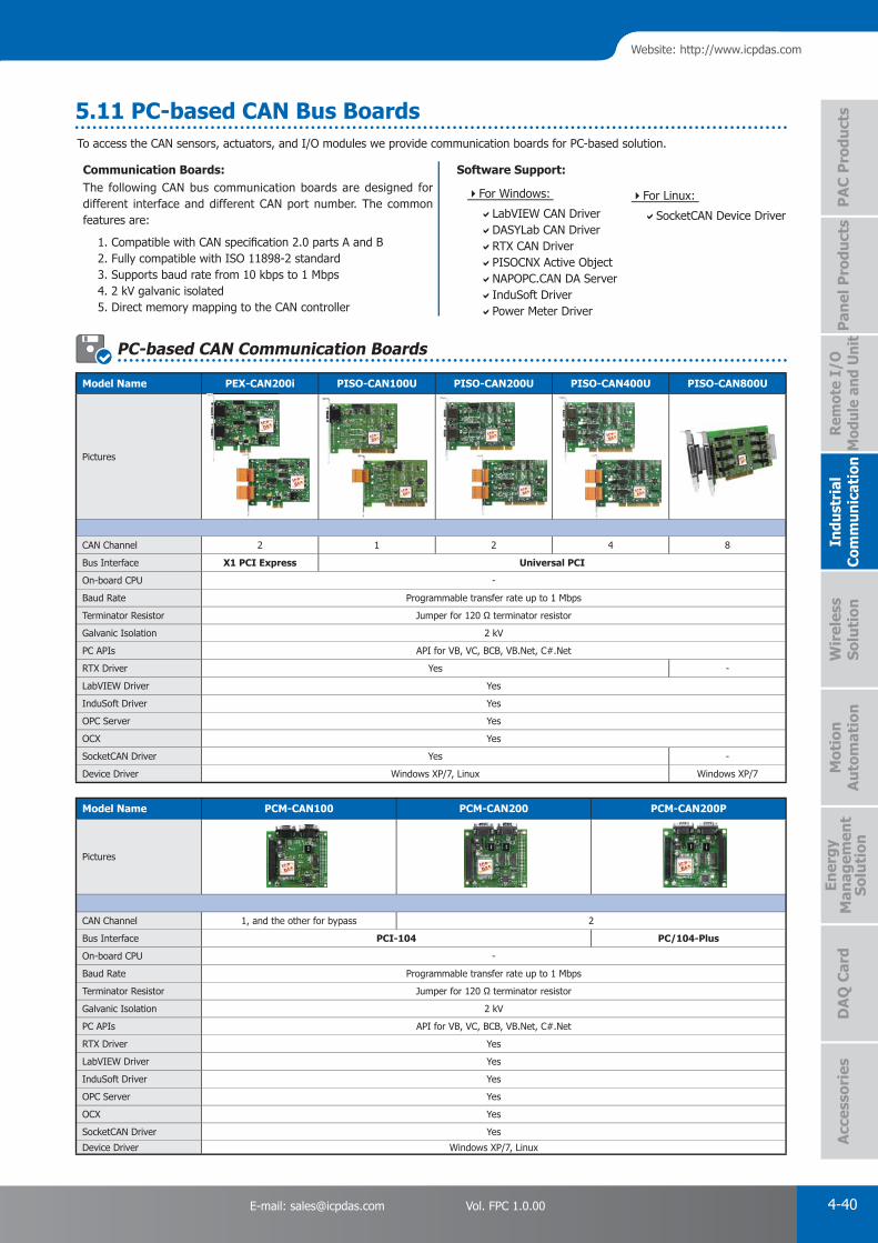
PAC Products
4-40E-mail: [email protected] Vol. FPC 1.0.00
Website: http://www.icpdas.com
PA
C P
rodu
cts
Pan
el P
rodu
cts
Rem
ote
I/O
M
odul
e an
d U
nit
DA
Q C
ard
Indu
stri
al
Com
mun
icat
ion
Wir
eles
s So
luti
onM
otio
n
Au
tom
atio
nA
cces
sori
esEn
ergy
M
anag
emen
tSo
luti
on
Model Name PCM-CAN100 PCM-CAN200 PCM-CAN200P
Pictures
CAN Channel 1, and the other for bypass 2
Bus Interface PCI-104 PC/104-Plus
On-board CPU -
Baud Rate Programmable transfer rate up to 1 Mbps
Terminator Resistor Jumper for 120 Ω terminator resistor
Galvanic Isolation 2 kV
PC APIs API for VB, VC, BCB, VB.Net, C#.Net
RTX Driver Yes
LabVIEW Driver Yes
InduSoft Driver Yes
OPC Server Yes
OCX Yes
SocketCAN Driver Yes
Device Driver Windows XP/7, Linux
Model Name PEX-CAN200i PISO-CAN100U PISO-CAN200U PISO-CAN400U PISO-CAN800U
Pictures
CAN Channel 2 1 2 4 8
Bus Interface X1 PCI Express Universal PCI
On-board CPU -
Baud Rate Programmable transfer rate up to 1 Mbps
Terminator Resistor Jumper for 120 Ω terminator resistor
Galvanic Isolation 2 kV
PC APIs API for VB, VC, BCB, VB.Net, C#.Net
RTX Driver Yes -
LabVIEW Driver Yes
InduSoft Driver Yes
OPC Server Yes
OCX Yes
SocketCAN Driver Yes -
Device Driver Windows XP/7, Linux Windows XP/7
To access the CAN sensors, actuators, and I/O modules we provide communication boards for PC-based solution.
Communication Boards:The following CAN bus communication boards are designed for different interface and different CAN port number. The common features are:
1. Compatible with CAN specifi cation 2.0 parts A and B 2. Fully compatible with ISO 11898-2 standard 3. Supports baud rate from 10 kbps to 1 Mbps 4. 2 kV galvanic isolated 5. Direct memory mapping to the CAN controller
Software Support:
LabVIEW CAN DriverDASYLab CAN DriverRTX CAN DriverPISOCNX Active Object NAPOPC.CAN DA ServerInduSoft DriverPower Meter Driver
SocketCAN Device Driver
For Windows: For Linux:
PC-based CAN Communication Boards
5.11 PC-based CAN Bus Boards

PAC Products
4-41 ICP DAS CO., LTD. Professional Provider of High Quality Industrial Computer Products and Data Acquisition Systems Vol. FPC 1.0.00
CA-0910-COptional CAN bus connector: CNT-CAN
•Screwed Terminal connector
•D-Sub 9-pin Connector
Connector Types: -T/-D
Each CAN bus board provide two type of connectors and, DB9 and Terminal Block.
Optional Cable for PISO-CAN800U
PISO-xxxxx-TPISO-xxxxx-D
Model Name PISO-CM100U PCM-CM100 PISO-DNM100U PISO-DNS100U PISO-CPM100U PCM-CPM100
Pictures
CAN Channel 1
Bus Interface Universal PCI PCI-104 Universal PCI PCI-104
On-board CPU Yes
On-board CPU OS MiniOS7
On-board CPU APIs C/C++ -
Default Firmware CAN 2.0A/2.0B DeviceNet Master DeviceNet Slave CANopen Master
EDS File Support - Yes
Baud Rate Programmable transfer rate up to 1 Mbps 125 k, 250 k, and 500 kbps10 k, 20 k, 50 k, 125 k, 250 k, 500 k, 800
k, 1 Mbps
Terminator Resistor Jumper for 120 Ω terminator resistor
Galvanic Isolation 2 kV
PC APIs API for VB, VC++, BCB, Delphi API for VB, VC++, VB.Net, C#.Net
LabVIEW Driver - Yes -
InduSoft Driver Yes - Yes
Power Meter Driver Yes - Yes
Device Driver Windows XP/7, Linux
CA-9-3705:
DB-37 Male (D-sub) to 4-Port DB-9 Male (D-sub) cable. 0.3 M (90°)
CA-9-3715D:
DB-37 Male (D-sub) to 4-Port DB-9 Male (D-sub) cable. 1.5 M (180°)
Installation
Step 1 Step 2 Step 3
Accessory
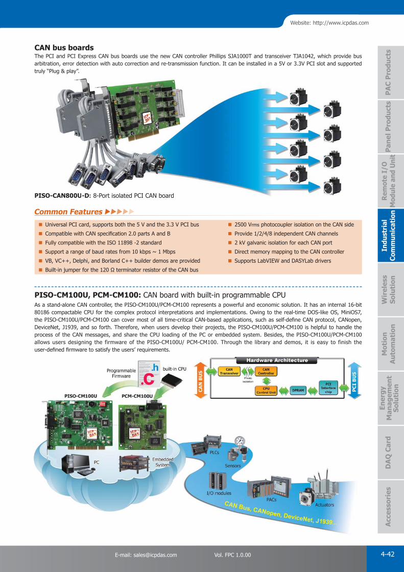
PAC Products
4-42E-mail: [email protected] Vol. FPC 1.0.00
Website: http://www.icpdas.com
PA
C P
rodu
cts
Pan
el P
rodu
cts
Rem
ote
I/O
M
odul
e an
d U
nit
DA
Q C
ard
Indu
stri
al
Com
mun
icat
ion
Wir
eles
s So
luti
onM
otio
n
Au
tom
atio
nA
cces
sori
esEn
ergy
M
anag
emen
tSo
luti
on
CAN bus boardsThe PCI and PCI Express CAN bus boards use the new CAN controller Phillips SJA1000T and transceiver TJA1042, which provide bus arbitration, error detection with auto correction and re-transmission function. It can be installed in a 5V or 3.3V PCI slot and supported truly “Plug & play”.
PISO-CAN800U-D: 8-Port isolated PCI CAN boardCAN800U-D: 8-Port isolated PCI CAN board
PISO-CM100U, PCM-CM100: CAN board with built-in programmable CPUAs a stand-alone CAN controller, the PISO-CM100U/PCM-CM100 represents a powerful and economic solution. It has an internal 16-bit 80186 compactable CPU for the complex protocol interpretations and implementations. Owing to the real-time DOS-like OS, MiniOS7, the PISO-CM100U/PCM-CM100 can cover most of all time-critical CAN-based applications, such as self-defi ne CAN protocol, CANopen, DeviceNet, J1939, and so forth. Therefore, when users develop their projects, the PISO-CM100U/PCM-CM100 is helpful to handle the process of the CAN messages, and share the CPU loading of the PC or embedded system. Besides, the PISO-CM100U/PCM-CM100 allows users designing the firmware of the PISO-CM100U/ PCM-CM100. Through the library and demos, it is easy to finish the user-defi ned fi rmware to satisfy the users’ requirements.
Common Features
Universal PCI card, supports both the 5 V and the 3.3 V PCI bus 2500 Vrms photocoupler isolation on the CAN side
Compatible with CAN specifi cation 2.0 parts A and B Provide 1/2/4/8 independent CAN channels
Fully compatible with the ISO 11898 -2 standard 2 kV galvanic isolation for each CAN port
Support a range of baud rates from 10 kbps ~ 1 Mbps Direct memory mapping to the CAN controller
VB, VC++, Delphi, and Borland C++ builder demos are provided Supports LabVIEW and DASYLab drivers
Built-in jumper for the 120 Ω terminator resistor of the CAN bus
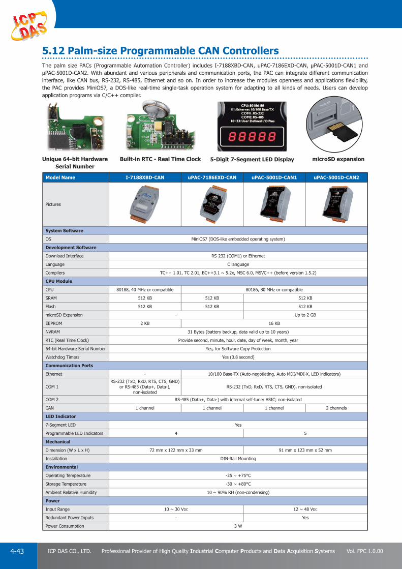
PAC Products
4-43 ICP DAS CO., LTD. Professional Provider of High Quality Industrial Computer Products and Data Acquisition Systems Vol. FPC 1.0.00
5.12 Palm-size Programmable CAN ControllersThe palm size PACs (Programmable Automation Controller) includes I-7188XBD-CAN, uPAC-7186EXD-CAN, μPAC-5001D-CAN1 and μPAC-5001D-CAN2. With abundant and various peripherals and communication ports, the PAC can integrate different communication interface, like CAN bus, RS-232, RS-485, Ethernet and so on. In order to increase the modules openness and applications fl exibility, the PAC provides MiniOS7, a DOS-like real-time single-task operation system for adapting to all kinds of needs. Users can develop application programs via C/C++ compiler.
Model Name I-7188XBD-CAN uPAC-7186EXD-CAN uPAC-5001D-CAN1 uPAC-5001D-CAN2
Pictures
System Software
OS MiniOS7 (DOS-like embedded operating system)
Development Software
Download Interface RS-232 (COM1) or Ethernet
Language C language
Compilers TC++ 1.01, TC 2.01, BC++3.1 ~ 5.2x, MSC 6.0, MSVC++ (before version 1.5.2)
CPU Module
CPU 80188, 40 MHz or compatible 80186, 80 MHz or compatible
SRAM 512 KB 512 KB 512 KB
Flash 512 KB 512 KB 512 KB
microSD Expansion - Up to 2 GB
EEPROM 2 KB 16 KB
NVRAM 31 Bytes (battery backup, data valid up to 10 years)
RTC (Real Time Clock) Provide second, minute, hour, date, day of week, month, year
64-bit Hardware Serial Number Yes, for Software Copy Protection
Watchdog Timers Yes (0.8 second)
Communication Ports
Ethernet - 10/100 Base-TX (Auto-negotiating, Auto MDI/MDI-X, LED indicators)
COM 1RS-232 (TxD, RxD, RTS, CTS, GND)
or RS-485 (Data+, Data-), non-isolated
RS-232 (TxD, RxD, RTS, CTS, GND), non-isolated
COM 2 RS-485 (Data+, Data-) with internal self-tuner ASIC; non-isolated
CAN 1 channel 1 channel 1 channel 2 channels
LED Indicator
7-Segment LED Yes
Programmable LED Indicators 4 5
Mechanical
Dimension (W x L x H) 72 mm x 122 mm x 33 mm 91 mm x 123 mm x 52 mm
Installation DIN-Rail Mounting
Environmental
Operating Temperature -25 ~ +75°C
Storage Temperature -30 ~ +80°C
Ambient Relative Humidity 10 ~ 90% RH (non-condensing)
Power
Input Range 10 ~ 30 VDC 12 ~ 48 VDC
Redundant Power Inputs - Yes
Power Consumption 3 W
microSD expansion Unique 64-bit Hardware Serial Number
Built-in RTC - Real Time Clock 5-Digit 7-Segment LED Display

PAC Products
4-44E-mail: [email protected] Vol. FPC 1.0.00
Website: http://www.icpdas.com
PA
C P
rodu
cts
Pan
el P
rodu
cts
Rem
ote
I/O
M
odul
e an
d U
nit
DA
Q C
ard
Indu
stri
al
Com
mun
icat
ion
Wir
eles
s So
luti
onM
otio
n
Au
tom
atio
nA
cces
sori
esEn
ergy
M
anag
emen
tSo
luti
on
CAN/CANopen/DeviceNet Communication Module (Parallel/Serial Bus)
Model Name I-8120W I-87120 I-8123W I-87123 I-8124W I-87124
Pictures
Communication
Interface ISO 11898-2 CAN
Port 1
Terminator 120 Ω Selected By Jumper
Max. Speed (K bps) 1000 1000 500
Controller Chip SJA1000T
Transceiver Chip 82C250
Protocol CAN 2.0 A/2.0 B CANopen CiA 301 ver 4.02, CiA 401 ver 2.1 DeviceNet Volume I ver 2.0, Volume II ver 2.0
System
Hot Swap - Yes - Yes - Yes
Data Communication Parallel Interface Serial Interface Parallel Interface Serial Interface Parallel Interface Serial Interface
User-defi ned Firmware Yes - -
Isolation 2500 Vrms
Power Consumption 2 W
Connector 5-pin Terminal Block
Optional Accessories CA-0904 Cable
CA-0904
Model Name I-8120W I-87120 I-8123W I-87123 I-8124W I-87124
PAC Driver Support
I-8000, iP-8000- BC, TC - BC, TC - BC, TC
VP-2111
WP-8000eVC++ 4.0, VB.Net 2005, C#.Net 2005
VP-2000
XP-8000-CE6, XP-8000-Atom-CE6 VB.Net 2005, C#.Net 2005, VC 2005
XP-8000, XP-8000-Atom VB.Net 2005, C#.Net 2005, VC 6
LP-8000 - GCC - GCC - GCC
CA-0904
These CAN bus communication modules are the solutions to the various CAN application requirements in PAC family with rich CAN bus protocols. The I-8123W, I-87123W, I-8124W, and I-87124W separately support CANopen and DeviceNet master protocols. Users can apply them in PAC to connect to CANopen and DeviceNet devices to reach various CANopen/DeviceNet systems easily.
For the especial CAN bus applications, the I-8120W and I-87120W are designed for users to apply in PAC series. The default firmware of I-8120W and I-87120W provides the transmission and reception of CAN bus messages in PAC. In addition, users can design the specific firmware in these modules to reduce the loading of the PAC in C language.
5.13 PAC-based CAN Modules
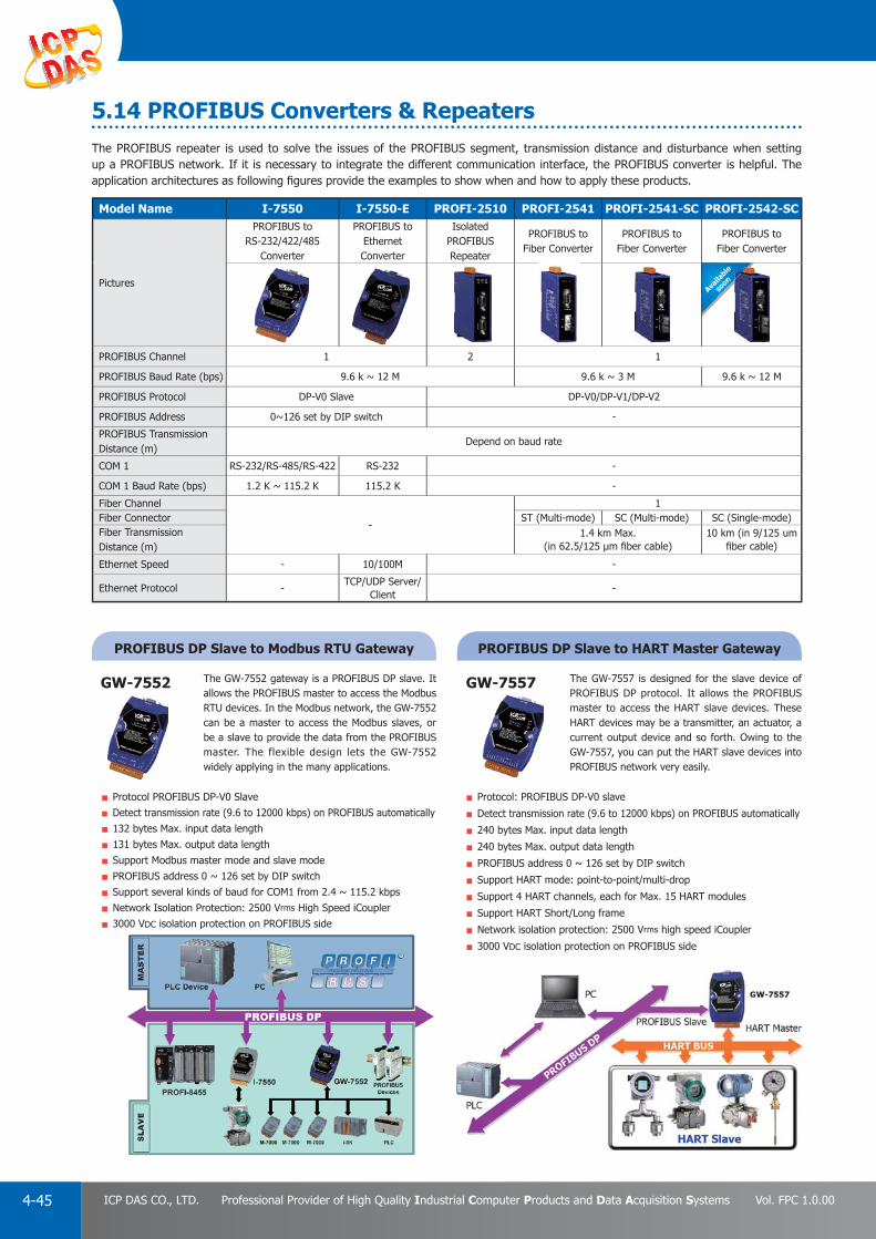
PAC Products
4-45 ICP DAS CO., LTD. Professional Provider of High Quality Industrial Computer Products and Data Acquisition Systems Vol. FPC 1.0.00
Availa
ble
soon
The PROFIBUS repeater is used to solve the issues of the PROFIBUS segment, transmission distance and disturbance when setting up a PROFIBUS network. If it is necessary to integrate the different communication interface, the PROFIBUS converter is helpful. The application architectures as following fi gures provide the examples to show when and how to apply these products.
Model Name I-7550 I-7550-E PROFI-2510 PROFI-2541 PROFI-2541-SC PROFI-2542-SC
Pictures
PROFIBUS to RS-232/422/485
Converter
PROFIBUS to Ethernet Converter
Isolated PROFIBUS Repeater
PROFIBUS to Fiber Converter
PROFIBUS to Fiber Converter
PROFIBUS to Fiber Converter
PROFIBUS Channel 1 2 1
PROFIBUS Baud Rate (bps) 9.6 k ~ 12 M 9.6 k ~ 3 M 9.6 k ~ 12 M
PROFIBUS Protocol DP-V0 Slave DP-V0/DP-V1/DP-V2
PROFIBUS Address 0~126 set by DIP switch -
PROFIBUS Transmission Distance (m)
Depend on baud rate
COM 1 RS-232/RS-485/RS-422 RS-232 -
COM 1 Baud Rate (bps) 1.2 K ~ 115.2 K 115.2 K -
Fiber Channel
-
1Fiber Connector ST (Multi-mode) SC (Multi-mode) SC (Single-mode)Fiber Transmission Distance (m)
1.4 km Max. (in 62.5/125 μm fi ber cable)
10 km (in 9/125 um fi ber cable)
Ethernet Speed - 10/100M -
Ethernet Protocol -TCP/UDP Server/
Client-
PROFIBUS DP Slave to HART Master GatewayPROFIBUS DP Slave to Modbus RTU Gateway
The GW-7557 is designed for the slave device of PROFIBUS DP protocol. It allows the PROFIBUS master to access the HART slave devices. These HART devices may be a transmitter, an actuator, a current output device and so forth. Owing to the GW-7557, you can put the HART slave devices into PROFIBUS network very easily.
The GW-7552 gateway is a PROFIBUS DP slave. It allows the PROFIBUS master to access the Modbus RTU devices. In the Modbus network, the GW-7552 can be a master to access the Modbus slaves, or be a slave to provide the data from the PROFIBUS master. The flexible design lets the GW-7552 widely applying in the many applications.
Protocol: PROFIBUS DP-V0 slave
Detect transmission rate (9.6 to 12000 kbps) on PROFIBUS automatically
240 bytes Max. input data length
240 bytes Max. output data length
PROFIBUS address 0 ~ 126 set by DIP switch
Support HART mode: point-to-point/multi-drop
Support 4 HART channels, each for Max. 15 HART modules
Support HART Short/Long frame
Network isolation protection: 2500 Vrms high speed iCoupler
3000 VDC isolation protection on PROFIBUS side
Protocol PROFIBUS DP-V0 Slave
Detect transmission rate (9.6 to 12000 kbps) on PROFIBUS automatically
132 bytes Max. input data length
131 bytes Max. output data length
Support Modbus master mode and slave mode
PROFIBUS address 0 ~ 126 set by DIP switch
Support several kinds of baud for COM1 from 2.4 ~ 115.2 kbps
Network Isolation Protection: 2500 Vrms High Speed iCoupler
3000 VDC isolation protection on PROFIBUS side
GW-7557GW-7552
p
5.14 PROFIBUS Converters & Repeaters

PAC Products
4-46E-mail: [email protected] Vol. FPC 1.0.00
Website: http://www.icpdas.com
PA
C P
rodu
cts
Pan
el P
rodu
cts
Rem
ote
I/O
M
odul
e an
d U
nit
DA
Q C
ard
Indu
stri
al
Com
mun
icat
ion
Wir
eles
s So
luti
onM
otio
n
Au
tom
atio
nA
cces
sori
esEn
ergy
M
anag
emen
tSo
luti
on
GW-7553
PROFIBUS DP Slave to Modbus TCP/RTU Gateway
Protocol PROFIBUS DP-V0 & DP-V1 slave
Detect transmission rate (9.6 to 12000 kbps) on PROFIBUS automatically
Support one 10/100 Base-TX Ethernet port
Support one RS-232 port
240 bytes Max. input data length
240 bytes Max. output data length
Support Modbus TCP/RTU/ASCII protocol
PROFIBUS address 0 ~ 126 set by DIP switch
Network isolation protection: 2500 Vrms high speed iCoupler
3000 VDC isolation protection on PROFIBUS side
The GW-7553 is used for data-exchange between the Modbus TCP/RTU network and the PROFIBUS network. It provides not only the Modbus TCP client and server functions, but the Modbus RTU master and slave functions. Therefore, the GW-7553 can satisfy most of the applications of the data transfer between Modbus and PROFIBUS.
GW-7553-CPM
PROFIBUS DP Slave to CANopen Master Gateway
Protocol: PROFIBUS DP-V0 slave
Detect Transmission rate (9.6 to 12000kbps) on PROFIBUS automatically
240 bytes Max. input data length
240 bytes Max. output data length
PROFIBUS address 0 ~ 126 set by DIP switch
Follow the CiA CANopen Standard DS-301 v4.02
Support Heartbeat function
Support Node Guarding
Support 230 Rx & 230 Tx PDO
Network isolation protection: 2500 Vrms high speed iCoupler
3000 VDC isolation protection on PROFIBUS side
The GW-7553-CPM is designed for the slave device of PROFIBUS DP protocol. It allows PROFIBUS master to access CANopen slave devices. These CANopen slave device may be a sensor, actuators, ICPDAS CAN-2000 series modules and so forth. In addition, we also provide the utility software for users to configure the GW-7553-CPM. By using this module, users can put their CANopen slave devices into PROFIBUS network very easily.

PAC Products
4-47 ICP DAS CO., LTD. Professional Provider of High Quality Industrial Computer Products and Data Acquisition Systems Vol. FPC 1.0.00
PROFINET to RS-232/422/485 Converter
The I-7580 is specially designed for PROFINET I/O device. It offers RS-232, RS-422, and RS-485 three kinds ofcommunication way. With the Hybrid COM 1 design, users can readily choose one type of com port to use. Through the GSDML fi le, it is easy to communicate with any standard PROFINET I/O controller.
Protocol: PROFINET IO DevicePROFINET Conformance Class B and RT Class 1Cyclic Time: 1ms (min)Generic GSDML File Provided (Version 2.25)Max. length of in/output data is 512/384 BytesProvide LED indicators
4 kV Contact ESD protection for any terminalWide range of power input (+10 ~ +30 VDC) and
operating temperature (-25 ~ +75°C)
I-7580
5.15 PROFINET Products
Cyclic Time: 1ms (min)Generic GSDML File Provided (Version 2.25)Max. length of in/output data is 512/384 BytesProvide LED indicators
p g p ( )
PRFINET Converter
PRFINET Gateways
The PROFINET gateway is used to solve data-exchanging between different communication network and PROFINET network. If it is necessary to integrate different communication protocols to PROFINET, the PROFINET gateway is helpful. The application architectures as following fi gures provide the examples to show when and how to apply these products.
Model Name GW-7662 GW-7663
Pictures
PROFINET to Modbus RTU Gateway PROFINET to Modbus TCP/RTU Gateway
PROFINET
Protocol IO device
Conformance Classes Class B
RT Classes Class 1
Cyclic Time 1 ms
COM port
Type 1 x RS-232/422/485
Baud Rate (bps) 2.4k ~ 115.2k
Protocol Modbus RTU/ASCII, Master/Slave
Ethernet portSpeed 10/100M
Protocol PROFINET IO device Modbus TCP Server/Client & PROFINET IO device

PAC Products
4-48E-mail: [email protected] Vol. FPC 1.0.00
Website: http://www.icpdas.com
PA
C P
rodu
cts
Pan
el P
rodu
cts
Rem
ote
I/O
M
odul
e an
d U
nit
DA
Q C
ard
Indu
stri
al
Com
mun
icat
ion
Wir
eles
s So
luti
onM
otio
n
Au
tom
atio
nA
cces
sori
esEn
ergy
M
anag
emen
tSo
luti
on
PROFINET to Modbus RTU Gateway
PROFINET to Modbus TCP Gateway
The GW-7662 gateway is a PROFINET I/O device that allows the PROFINET controller to access the Modbus RTU devices. In the Modbus network, the GW-7662 can be a master to access the Modbus slaves, or be a slave to provide the data from the PROFINET controller. The fl exible design lets the GW-7662 widely applying in the many applications.
The GW-7663 is used for data-exchange between the Modbus TCP/RTU network and the PROFINET network. It provides not only the Modbus TCP client and server functions, but the Modbus RTU master and slave functions. Therefore, the GW-7663 can satisfy most of the applications of the data transfer between Modbus and PROFINET.
Protocol: PROFINET IO DevicePROFINET Conformance Class B and RT Class 1Cyclic Time: 1ms (min)Generic GSDML File Provided (Version 2.25)Max length of in/output data is 512/512 BytesSupport Modbus RTU/ASCII protocol
Protocol: PROFINET I/O DevicePROFINET Conformance Class B and RT Class 1Cyclic Time: 1 ms (min)Generic GSDML File Provided (Version 2.25)Max length of in/output data is 512/512 BytesSupport Modbus TCP/RTU/ASCII protocolProvide LED indicators4 kV Contact ESD protection for any terminalWide range of power input (+10 ~ +30 VDC) and
operating temperature (-25 ~ +75°C)
Support several kinds of baud for COM1 from 2.4 ~ 115.2 kbps
Provide voltage overload protectionProvide LED indicators4 kV Contact ESD protection for any terminal Wide range of power input (+10 ~ +30 VDC)
and operating temperature (-25 ~ +75°C)
GW-7662
GW-7663
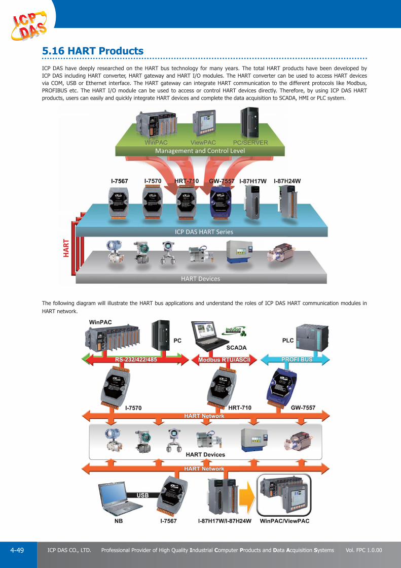
PAC Products
4-49 ICP DAS CO., LTD. Professional Provider of High Quality Industrial Computer Products and Data Acquisition Systems Vol. FPC 1.0.00
ICP DAS have deeply researched on the HART bus technology for many years. The total HART products have been developed by ICP DAS including HART converter, HART gateway and HART I/O modules. The HART converter can be used to access HART devices via COM, USB or Ethernet interface. The HART gateway can integrate HART communication to the different protocols like Modbus, PROFIBUS etc. The HART I/O module can be used to access or control HART devices directly. Therefore, by using ICP DAS HART products, users can easily and quickly integrate HART devices and complete the data acquisition to SCADA, HMI or PLC system.
The following diagram will illustrate the HART bus applications and understand the roles of ICP DAS HART communication modules in HART network.
5.16 HART Products
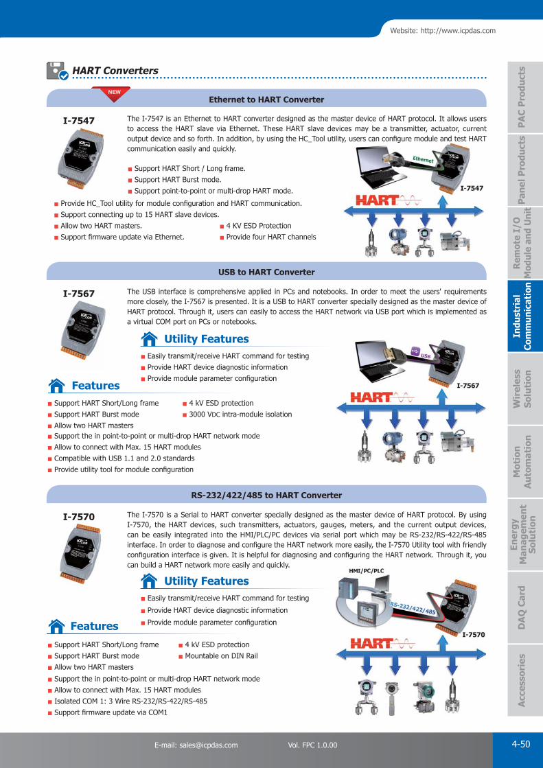
PAC Products
4-50E-mail: [email protected] Vol. FPC 1.0.00
Website: http://www.icpdas.com
PA
C P
rodu
cts
Pan
el P
rodu
cts
Rem
ote
I/O
M
odul
e an
d U
nit
DA
Q C
ard
Indu
stri
al
Com
mun
icat
ion
Wir
eles
s So
luti
onM
otio
n
Au
tom
atio
nA
cces
sori
esEn
ergy
M
anag
emen
tSo
luti
on
Ethernet to HART Converter
USB to HART Converter
RS-232/422/485 to HART Converter
The I-7547 is an Ethernet to HART converter designed as the master device of HART protocol. It allows users to access the HART slave via Ethernet. These HART slave devices may be a transmitter, actuator, current output device and so forth. In addition, by using the HC_Tool utility, users can confi gure module and test HART communication easily and quickly.
The USB interface is comprehensive applied in PCs and notebooks. In order to meet the users' requirements more closely, the I-7567 is presented. It is a USB to HART converter specially designed as the master device of HART protocol. Through it, users can easily to access the HART network via USB port which is implemented as a virtual COM port on PCs or notebooks.
The I-7570 is a Serial to HART converter specially designed as the master device of HART protocol. By using I-7570, the HART devices, such transmitters, actuators, gauges, meters, and the current output devices, can be easily integrated into the HMI/PLC/PC devices via serial port which may be RS-232/RS-422/RS-485 interface. In order to diagnose and confi gure the HART network more easily, the I-7570 Utility tool with friendly confi guration interface is given. It is helpful for diagnosing and confi guring the HART network. Through it, you can build a HART network more easily and quickly.
Support HART Short / Long frame.
Support HART Burst mode.
Support point-to-point or multi-drop HART mode.
Provide HC_Tool utility for module confi guration and HART communication.
Support connecting up to 15 HART slave devices.
Allow two HART masters.
Support fi rmware update via Ethernet. 4 KV ESD Protection
Provide four HART channels
I-7547
I-7567
I-7570
HART Converters
Support HART Short/Long frame
Support HART Burst mode
Allow two HART masters
4 kV ESD protection
3000 VDC intra-module isolation
Support the in point-to-point or multi-drop HART network mode
Allow to connect with Max. 15 HART modules
Compatible with USB 1.1 and 2.0 standards
Provide utility tool for module confi guration
Easily transmit/receive HART command for testing
Provide HART device diagnostic information
Provide module parameter confi guration
Utility Features
Easily transmit/receive HART command for testing
Provide HART device diagnostic information
Provide module parameter confi guration
Utility Features
Features
Features
NEW
Support HART Short/Long frame
Support HART Burst mode
Allow two HART masters
4 kV ESD protection
Mountable on DIN Rail
Support the in point-to-point or multi-drop HART network mode
Allow to connect with Max. 15 HART modules
Isolated COM 1: 3 Wire RS-232/RS-422/RS-485
Support fi rmware update via COM1

PAC Products
4-51 ICP DAS CO., LTD. Professional Provider of High Quality Industrial Computer Products and Data Acquisition Systems Vol. FPC 1.0.00
Support HART Short/Long frame
Support HART Burst mode
Allow two HART Masters
Working in Point-to-Point Mode
4 Independent Analog Output Signals
Support Acquire Long Frame Address Automatically
Built-in 2 Form A and 2 Form C relays
Intelligent Activate Relay Alarm automatically
Features
HRT-227CS
Fiber to HART Converter
Support HART Short/Long frame
Support HART Burst mode
Support point-to-point or multi-drop HART mode
Support connecting up to 15 HART slave devices
Allow two HART masters
Provide HC_Tool utility for module confi guration
Fiber Type: SC ; Single mode ; 100 Base-FX
Maximum transmission distance up to 30 km
Selectable 250 Ω load resistor
The HART port with the same Group ID can
Search all HART devices automatically
Provide HART Universal & Common-Practice
Command (v6.0) for HART device confi guration
Provide module confi guration and HART
The HRT-227CS is a HART to Fiber converter paired used to extend HART communication distance via single mode fi ber optic transmission medium.
y
Features
Utility Features
HRT-228-A4
HART-to-Analog Converter and Loop Monitor
The HRT-228-A4 Converter enables the conversion of a digital multivariable HART signal into four independent 4 ~ 20 mA analog process variables.
Provide the confi guration of HRT-228-A4
Provide the diagnostic information of HRT-228-A4
module and HART device
Provide send HART command transparently to
HART device
Provide "Load/Save" module confi guration fi le to
apply to other HRT-228-A4 quickly
Utility Features
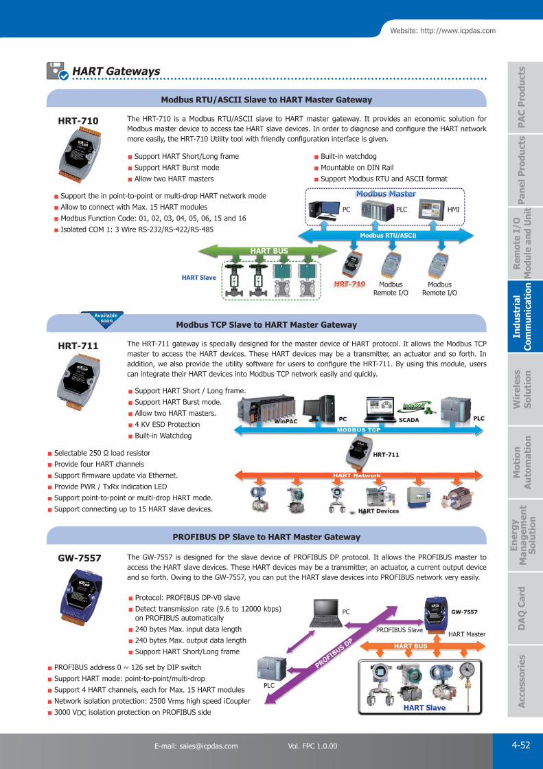
PAC Products
4-52E-mail: [email protected] Vol. FPC 1.0.00
Website: http://www.icpdas.com
PA
C P
rodu
cts
Pan
el P
rodu
cts
Rem
ote
I/O
M
odul
e an
d U
nit
DA
Q C
ard
Indu
stri
al
Com
mun
icat
ion
Wir
eles
s So
luti
onM
otio
n
Au
tom
atio
nA
cces
sori
esEn
ergy
M
anag
emen
tSo
luti
on
Modbus RTU/ASCII Slave to HART Master Gateway
Modbus TCP Slave to HART Master Gateway
PROFIBUS DP Slave to HART Master Gateway
The HRT-710 is a Modbus RTU/ASCII slave to HART master gateway. It provides an economic solution for Modbus master device to access tae HART slave devices. In order to diagnose and confi gure the HART network more easily, the HRT-710 Utility tool with friendly confi guration interface is given.
The HRT-711 gateway is specially designed for the master device of HART protocol. It allows the Modbus TCP master to access the HART devices. These HART devices may be a transmitter, an actuator and so forth. In addition, we also provide the utility software for users to confi gure the HRT-711. By using this module, users can integrate their HART devices into Modbus TCP network easily and quickly.
The GW-7557 is designed for the slave device of PROFIBUS DP protocol. It allows the PROFIBUS master to access the HART slave devices. These HART devices may be a transmitter, an actuator, a current output device and so forth. Owing to the GW-7557, you can put the HART slave devices into PROFIBUS network very easily.
Support HART Short/Long frame
Support HART Burst mode
Allow two HART masters
Built-in watchdog
Mountable on DIN Rail
Support Modbus RTU and ASCII format
Support the in point-to-point or multi-drop HART network mode
Allow to connect with Max. 15 HART modules
Modbus Function Code: 01, 02, 03, 04, 05, 06, 15 and 16
Isolated COM 1: 3 Wire RS-232/RS-422/RS-485
HRT-710
HRT-711
GW-7557
Support HART Short / Long frame.
Support HART Burst mode.
Allow two HART masters.
4 KV ESD Protection
Built-in Watchdog
Protocol: PROFIBUS DP-V0 slave
Detect transmission rate (9.6 to 12000 kbps) on PROFIBUS automatically
240 bytes Max. input data length
240 bytes Max. output data length
Support HART Short/Long frame
PROFIBUS address 0 ~ 126 set by DIP switch
Support HART mode: point-to-point/multi-drop
Support 4 HART channels, each for Max. 15 HART modules
Network isolation protection: 2500 Vrms high speed iCoupler
3000 VDC isolation protection on PROFIBUS side
Available soon
Selectable 250 Ω load resistor
Provide four HART channels
Support fi rmware update via Ethernet.
Provide PWR / TxRx indication LED
Support point-to-point or multi-drop HART mode.
Support connecting up to 15 HART slave devices.
HART Gateways
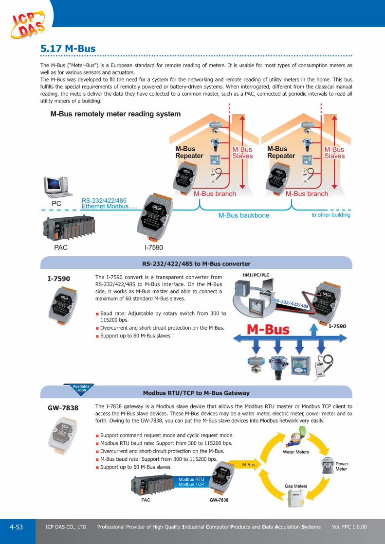
PAC Products
4-53 ICP DAS CO., LTD. Professional Provider of High Quality Industrial Computer Products and Data Acquisition Systems Vol. FPC 1.0.00
5.17 M-BusThe M-Bus ("Meter-Bus") is a European standard for remote reading of meters. It is usable for most types of consumption meters as well as for various sensors and actuators.The M-Bus was developed to fi ll the need for a system for the networking and remote reading of utility meters in the home. This bus fulfi lls the special requirements of remotely powered or battery-driven systems. When interrogated, different from the classical manual reading, the meters deliver the data they have collected to a common master, such as a PAC, connected at periodic intervals to read all utility meters of a building.
Baud rate: Adjustable by rotary switch from 300 to 115200 bps.
Overcurrent and short-circuit protection on the M-Bus.
Support up to 60 M-Bus slaves.
Support command request mode and cyclic request mode.
Modbus RTU baud rate: Support from 300 to 115200 bps.
Overcurrent and short-circuit protection on the M-Bus.
M-Bus baud rate: Support from 300 to 115200 bps.
Support up to 60 M-Bus slaves.
RS-232/422/485 to M-Bus converter
Modbus RTU/TCP to M-Bus Gateway
The I-7590 convert is a transparent converter from RS-232/422/485 to M-Bus interface. On the M-Bus side, it works as M-Bus master and able to connect a maximum of 60 standard M-Bus slaves.
The I-7838 gateway is a Modbus slave device that allows the Modbus RTU master or Modbus TCP client to access the M-Bus slave devices. These M-Bus devices may be a water meter, electric meter, power meter and so forth. Owing to the GW-7838, you can put the M-Bus slave devices into Modbus network very easily.
I-7590
GW-7838
mand request mode and cyclic request mode.baud rate: Support from 300 to 115200 bps.
and short-circuit protection on the M-Bus.ate: Support from 300 to 115200 bps.
o 60 M-Bus slaves.
Available soon

Industrial Wireless Communication Products P 5-1
GPS Products P 5-12
Radio Modems P 5-2
1
6
2
ZigBee Products P 5-85
● 5.1 ZigBee Converter - - - - - - - - - - - - - - - - - - - - - - - - - - - - - - - - - - - P 5-8 ● 5.2 ZigBee Repeater - - - - - - - - - - - - - - - - - - - - - - - - - - - - - - - - - - - - P 5-9 ● 5.3 ZigBee Bridge - - - - - - - - - - - - - - - - - - - - - - - - - - - - - - - - - - - - - - P 5-9 ● 5.4 ZigBee I/O Module - - - - - - - - - - - - - - - - - - - - - - - - - - - - - - - - - - P 5-10 ● 5.5 ZigBee I/O Pair-connection Modules - - - - - - - - - - - - - - - - - - - - - - - P 5-11
Infrared Products P 5-137
● 7.1 IR Learning Remote Module - - - - - - - - - - - - - - - - - - - - - - - - - - - - - P 5-13 ● 7.2 IR Controlled Power Relay Module - - - - - - - - - - - - - - - - - - - - - - - - - P 5-13 ● 7.3 Accessories - - - - - - - - - - - - - - - - - - - - - - - - - - - - - - - - - - - - - - - P 5-13
WLAN Wireless Products P 5-54
● 4.1 WLAN Converter/Gateway Bridge - - - - - - - - - - - - - - - - - - - - - - - - - P 5-5 ● 4.2 WLAN I/O Modules - - - - - - - - - - - - - - - - - - - - - - - - - - - - - - - - - - P 5-5 ● 4.3 WLAN I/O Modules with Metal Case - - - - - - - - - - - - - - - - - - - - - - - P 5-6 ● 4.4 Wi-Fi Access Point - - - - - - - - - - - - - - - - - - - - - - - - - - - - - - - - - - - P 5-6
2G/3G Products P 5-33
● 3.1 2G/3G Modem - - - - - - - - - - - - - - - - - - - - - - - - - - - - - - - - - - - - - P 5-3 ● 3.2 SMS Alarm Controller - - - - - - - - - - - - - - - - - - - - - - - - - - - - - - - - - P 5-4 ● 3.3 GPRS/3G Gateway - - - - - - - - - - - - - - - - - - - - - - - - - - - - - - - - - - - P 5-4 ● 3.4 2G/3G Programmable Automation Controller - - - - - - - - - - - - - - - - - - P 5-4
Wireless SolutionWireless SolutionWireless Solution 5

PAC Products
5-1 ICP DAS CO., LTD. Professional Provider of High Quality Industrial Computer Products and Data Acquisition Systems Vol. FPC 1.0.00
1. Industrial Wireless Communication ProductsIndustrial Wireless Communication creates new prospects for automation. In the harsh environment, chemicals, vibrations, or moving parts could potentially damage cabling. Industrial Wireless Communication system substantially reduces cost and time for the installation and maintenance of the large number of cable, thus makes plants setup and reconfi guration easy and safe.
ICP DAS provides a great variety of wireless products with modular and universal solution specially designed for industrial harsh environment.
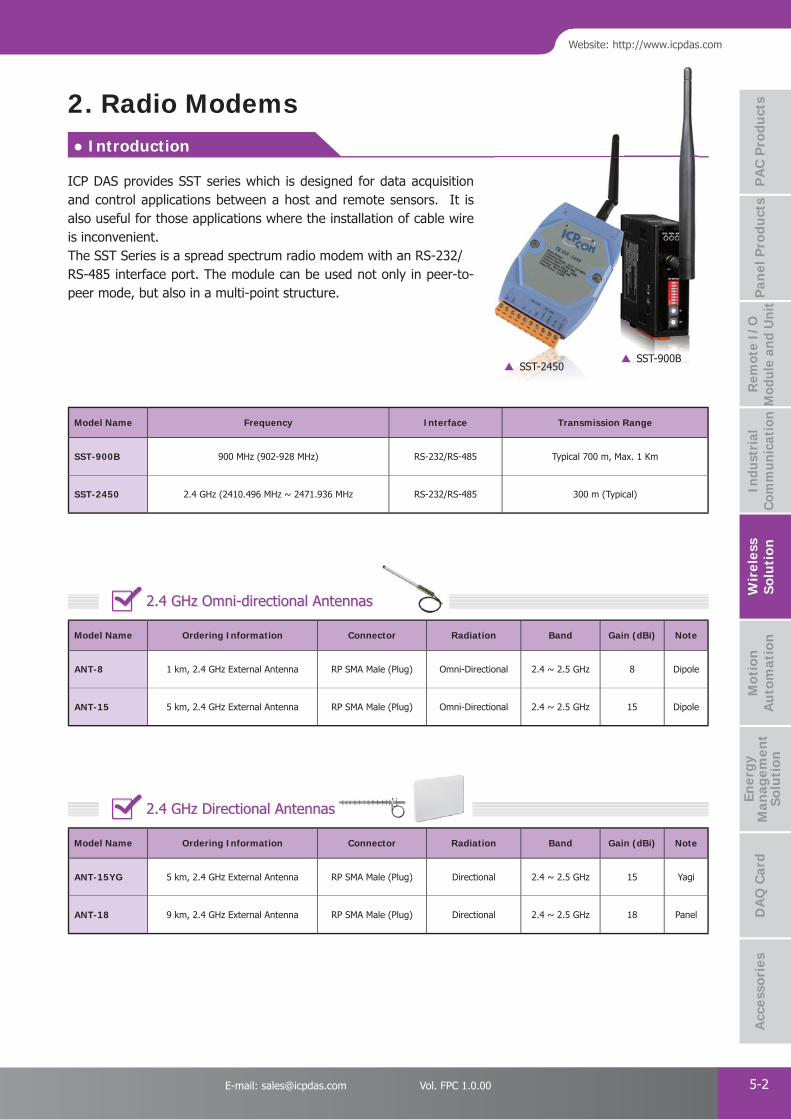
PAC Products
5-2E-mail: [email protected] Vol. FPC 1.0.00
Website: http://www.icpdas.com
PA
C P
rodu
cts
Pan
el P
rodu
cts
Rem
ote
I/O
M
odul
e an
d U
nit
DA
Q C
ard
Indu
stri
al
Com
mun
icat
ion
Wir
eles
s So
luti
onM
otio
n
Au
tom
atio
nA
cces
sori
esEn
ergy
M
anag
emen
tSo
luti
on
ICP DAS provides SST series which is designed for data acquisition and control applications between a host and remote sensors. It is also useful for those applications where the installation of cable wire is inconvenient.The SST Series is a spread spectrum radio modem with an RS-232/RS-485 interface port. The module can be used not only in peer-to-peer mode, but also in a multi-point structure.
● Introduction
2. Radio Modems
Model Name Frequency Interface Transmission Range
SST-900B 900 MHz (902-928 MHz) RS-232/RS-485 Typical 700 m, Max. 1 Km
SST-2450 2.4 GHz (2410.496 MHz ~ 2471.936 MHz RS-232/RS-485 300 m (Typical)
Model Name Ordering Information Connector Radiation Band Gain (dBi) Note
ANT-8 1 km, 2.4 GHz External Antenna RP SMA Male (Plug) Omni-Directional 2.4 ~ 2.5 GHz 8 Dipole
ANT-15 5 km, 2.4 GHz External Antenna RP SMA Male (Plug) Omni-Directional 2.4 ~ 2.5 GHz 15 Dipole
Model Name Ordering Information Connector Radiation Band Gain (dBi) Note
ANT-15YG 5 km, 2.4 GHz External Antenna RP SMA Male (Plug) Directional 2.4 ~ 2.5 GHz 15 Yagi
ANT-18 9 km, 2.4 GHz External Antenna RP SMA Male (Plug) Directional 2.4 ~ 2.5 GHz 18 Panel
2.4 GHz Omni-directional Antennas
2.4 GHz Directional Antennas
SST-900BSST-2450

PAC Products
5-3 ICP DAS CO., LTD. Professional Provider of High Quality Industrial Computer Products and Data Acquisition Systems Vol. FPC 1.0.00
● Introduction
3. 2G/3G Products
Model Name Frequency
(MHz)ResetInput
MIC Input/Audio Output
GPSTCP/IP Stack
Baud Rate(bps)
Interface Driver Housing
GTM-201-RS2322G (GSM/GPRS):
850/900/1800/1900
Yes Yes
-
Yes 9.6 K ~ 115.2 K
RS-232 Windows XP / 7Windows CE
LinuxPlastic
GTM-201-USB2G (GSM/GPRS):
850/900/1800/1900- USB 2.0
GTM-201-3GWA
2G (GSM/GPRS): 850/900/1800/1900
-USB 2.0RS-232
Windows XP / 7Linux
Plastic
3G (UMTS/HSDPA/HSUPA):2100/1900/850
GTM-201P-3GWA
2G (GSM/GPRS): 850/900/1800/1900
YesUSB 2.0RS-232
GPS3G (UMTS/HSDPA/HSUPA):2100/1900/850
GTM-203M-3GWA
2G (GSM/GPRS): 850/900/1800/1900
-USB 2.0RS-232
Windows XP / 7 / 8Linux
Metal3G (UMTS/HSDPA/HSUPA):
2100/1900/850
Model Name Frequency
(MHz)GPS Interface Max. Download Speed AT Command TCP/IP Protocol
I-8212W-3GWA
2G (GSM/GPRS): 850/900/1800/1900
- 115.2 Kbps
Yes Yes
3G (UMTS/HSDPA/HSUPA):2100/1900/850
I-8213W-3GWA
2G (GSM/GPRS): 850/900/1800/1900
Yes 115.2 Kbps3G (UMTS/HSDPA/HSUPA):
2100/1900/850
Stand Alone Modem
2G/3G Modem for PACs
3.1 2G/3G Modem
ICP DAS 2G/3G wireless solutions are uniquely designed to meet the challenges of implementing and managing a small, medium and large number of unmanned remote devices as well as mobile terminals using the 2G/3G telecom network. The ICP DAS 2G/3G wireless system is comprised of intelligent 2G/3G modems with versatile interfaces, a 2G/3G Data Server (DS), and 2G/3G PACs with embedded dynamic IP resolution technology to help system integrators and application service providers can quickly integrate 2G/3G technology into their own solutions, and save development time with reduced costs and assured performance.
There is no need to build an expensive fixed line network.Enable any devices to be connected to the Internet via serial port over a 2G/3G network.The most efficient method of handling data over a 2G/3G wireless network and the Internet.A full turnkey solution that is designed for both fixed and mobile machine to machine applications. Reliable GSM/GPRS/EDGE/UMTS/HSPA network connectivity, providing fast and cost-effective long-range wireless applications GT-530 G-4500
MIC I
Advantages & Benefi ts

PAC Products
5-4E-mail: [email protected] Vol. FPC 1.0.00
Website: http://www.icpdas.com
PA
C P
rodu
cts
Pan
el P
rodu
cts
Rem
ote
I/O
M
odul
e an
d U
nit
DA
Q C
ard
Indu
stri
al
Com
mun
icat
ion
Wir
eles
s So
luti
onM
otio
n
Au
tom
atio
nA
cces
sori
esEn
ergy
M
anag
emen
tSo
luti
on
3.2 SMS Alarm Controller
3.3 GPRS/3G Gateway
3.4 3G Programmable Automation Controller
Model Name Function Interface GSM/GPRS Interface 3G Interface I/O
GT-530 SMS Alert Controller 1 x RS232 Tri-Band GSM/GPRS - 10 DI, 2 DO
SMS-530 SMS Alert Controller 1 x RS232
Quad-Band GSM /GPRS
WCDMA Quad Band 10 DI, 2 DO
GT-531 Modbus SMS Alert Controller 1 x RS232/485 - -
SMS-531 Modbus SMS Alert Controller 1 x RS232/485 WCDMA Quad Band -
GT-534 SMS Alert Controller 1 x RS232/485 - 1 AI, 6 DI, 2 DO
SMS-534 SMS/Voice Alert Controller 1 x RS232/485 WCDMA Quad Band 1 AI, 6 DI, 2 DO
Model Name Function Interface GSM/GPRS Interface 3G Interface GPS I/O
GT-540 GPRS RTU 1 x RS232/485
Quad-Band GSM /GPRS
- - 1 AI, 6 DI, 2 DO
GT-540-3GWA GPRS RTU 1 x RS232/485 WCDMA / HSDPA / HSUPA - -
GT-540P 3G RTU 1 x RS232/4851 x RS232/485 - Yes -
GT-540P-3GWA 3G RTU 1 x RS232/485 WCDMA / HSDPA / HSUPA Yes -
GT-541 GPRS Gateway 1 x RS232/485 - - -
RMV-514 GPRS Gateway 1 x RS232/485 - - 1 AI, 6 DI, 2 DO
RMV-531 2G/3G Gateway1 x RS232
1 x RS-485WCDMA / HSDPA / HSUPA - -
GRP-520 2G/3G Router1 x RS232/485
1 x EthernetWCDMA / HSDPA / HSUPA - -
Model Name OS Interface I/OFrequency
(MHz)LCM(Dot)
GPSPowerSaving
Solar Charging
G-4513-3GWA
MiniOS71 × Ethernet1 × RS-2321 × RS-485
3 x DO 3 x DI8 x AI
1 x Relay
2G (GSM/GPRS):850/900/1800/1900
3G (UMTS/HSDPA/HSUPA):2100/1900/850
--
Yesfor 12V Lead-Acid Battery
G-4513D-3GWA 128 × 64
G-4513P-3GWA -Yes
G-4513PD-3GWA 128 × 64
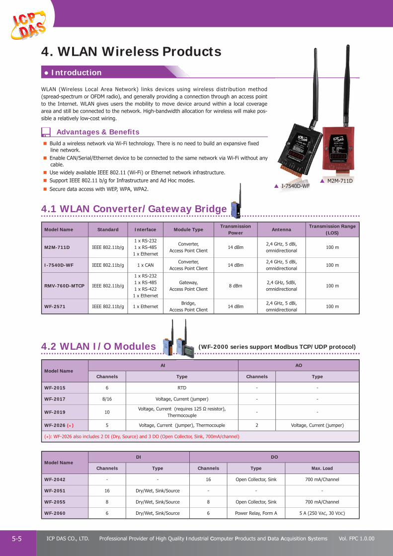
PAC Products
5-5 ICP DAS CO., LTD. Professional Provider of High Quality Industrial Computer Products and Data Acquisition Systems Vol. FPC 1.0.00
Model Name AI AO
Channels Type Channels Type
WF-2015 6 RTD - -
WF-2017 8/16 Voltage, Current (jumper) - -
WF-2019 10Voltage, Current (requires 125 Ω resistor),
Thermocouple- -
WF-2026 (*) 5 Voltage, Current (jumper), Thermocouple 2 Voltage, Current (jumper)
(*): WF-2026 also includes 2 DI (Dry, Source) and 3 DO (Open Collector, Sink, 700mA/channel)
Model Name DI DO
Channels Type Channels Type Max. Load
WF-2042 - - 16 Open Collector, Sink 700 mA/Channel
WF-2051 16 Dry/Wet, Sink/Source - - -
WF-2055 8 Dry/Wet, Sink/Source 8 Open Collector, Sink 700 mA/Channel
WF-2060 6 Dry/Wet, Sink/Source 6 Power Relay, Form A 5 A (250 VAC, 30 VDC)
Model Name Standard Interface Module TypeTransmission
PowerAntenna
Transmission Range(LOS)
M2M-711D IEEE 802.11b/g1 x RS-2321 x RS-4851 x Ethernet
Converter, Access Point Client
14 dBm2,4 GHz, 5 dBi,omnidirectional
100 m
I-7540D-WF IEEE 802.11b/g 1 x CANConverter,
Access Point Client14 dBm
2,4 GHz, 5 dBi, omnidirectional
100 m
RMV-760D-MTCP IEEE 802.11b/g
1 x RS-2321 x RS-4851 x RS-4221 x Ethernet
Gateway, Access Point Client
8 dBm2,4 GHz, 5dBi, omnidirectional
100 m
WF-2571 IEEE 802.11b/g 1 x EthernetBridge,
Access Point Client14 dBm
2,4 GHz, 5 dBi, omnidirectional
100 m
WLAN (Wireless Local Area Network) links devices using wireless distribution method (spread-spectrum or OFDM radio), and generally providing a connection through an access point to the Internet. WLAN gives users the mobility to move device around within a local coverage area and still be connected to the network. High-bandwidth allocation for wireless will make pos-sible a relatively low-cost wiring.
● Introduction
4. WLAN Wireless Products
4.2 WLAN I/O Modules
4.1 WLAN Converter/Gateway Bridge
M2M-711DI-7540D-WF
Build a wireless network via Wi-Fi technology. There is no need to build an expansive fixed line network.Enable CAN/Serial/Ethernet device to be connected to the same network via Wi-Fi without any cable.Use widely available IEEE 802.11 (Wi-Fi) or Ethernet network infrastructure.Support IEEE 802.11 b/g for Infrastructure and Ad Hoc modes.
Secure data access with WEP, WPA, WPA2.
(WF-2000 series support Modbus TCP/UDP protocol)
Advantages & Benefi ts

PAC Products
5-6E-mail: [email protected] Vol. FPC 1.0.00
Website: http://www.icpdas.com
PA
C P
rodu
cts
Pan
el P
rodu
cts
Rem
ote
I/O
M
odul
e an
d U
nit
DA
Q C
ard
Indu
stri
al
Com
mun
icat
ion
Wir
eles
s So
luti
onM
otio
n
Au
tom
atio
nA
cces
sori
esEn
ergy
M
anag
emen
tSo
luti
on
The UniFi AP System from the UBIQUITI NETWORKS is a scalable enterprise access point solution
Supports all the ICP DAS’s Wi-Fi modulesEasy to deploy and manageUniFi Controller softwareCan be set in the same SSID and RF channelSupports “Load Balancing” function
4.3 WLAN I/O Modules with Metal Case (Support Modbus TCP/UDP protocol)
Model Name DI DO
Channels Type Channels Type Max. Load
WFM-P16C16 16 Dry/Wet, Sink/Source 16 Open Collector, Source 650 mA/channel
WFM-P16R10 16 Dry/Wet, Sink/Source 10 Power Relay, Form A 5A/channel
WFM-R14 - - 14Power Relay,
2 Form A / 12 Form CForm A: 5A/chForm C: 6A/ch
WFM-P32 32 Dry/Wet, Sink/Source - - -
WFM-C32 - - 32 Open Collector, Source 650 mA/channel
4.4 Wi-Fi Access Point
Part No. Description
UniFi AP UBIQUITI MIMO indoor AP, speeds up to 300 Mbps with a range of up to 122 m.
UniFi AP-LR UBIQUITI MIMO indoor AP, speeds up to 300 Mbps with a range of up to 183 m.
UniFi AP-Outdoor+UBIQUITI MIMO outdoor AP, speeds up to 300 Mbps with a range of up to 183 m, utilizes UBIQUITI innovative Multi-Lane RF technology.
Model Name UniFi AP UniFi AP-LR UniFi AP-Outdoor+
Pictures
indoor AP indoor AP offers Longer Range Outdoor AP
2.4 G Yes Yes Yes
2.4 G Speed 300 Mbps 300 Mbps 300 Mbps
Range 122 m (400ft) 183 m (600ft) 183 m (600ft)
Multi-Lane RF – – Yes
2nd Ethernet Port – – Yes
Wi-Fi standards 801.11 b/g/n 801.11 b/g/n 801.11 b/g/n
Ubiquiti PoE Yes Yes Yes
External Antennas – – Yes
Maximum TX Power 20 dBm 27 dBm 28 dBm
Power Consumption 4 W 6 W 8 W
Dimensions (W x L x D) 200 x 200 x 36.5 mm 200 x 200 x 36.5 mm 205 x 83 x 37 mm
Operating Temperature -10 to 70°C -10 to 70°C -30 to 65°C
Operating Humidity 5-80% Non-Condensing 5-80% Non-Condensing 5-95% Non-Condensing
++
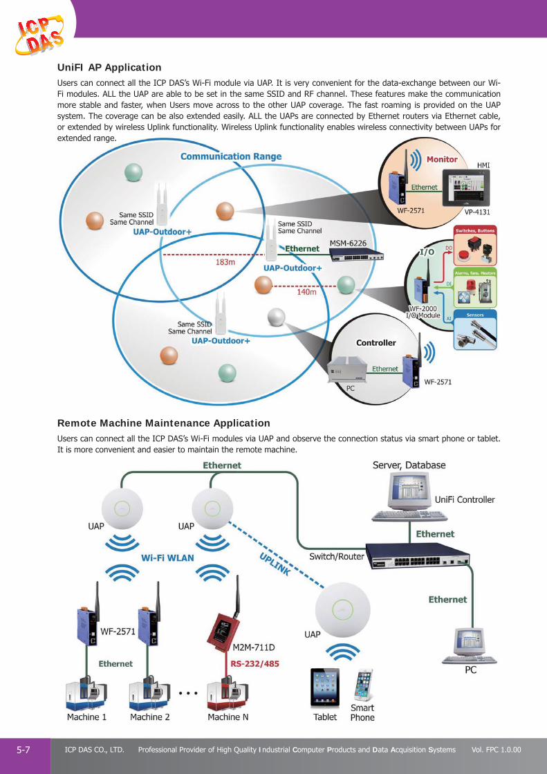
PAC Products
5-7 ICP DAS CO., LTD. Professional Provider of High Quality Industrial Computer Products and Data Acquisition Systems Vol. FPC 1.0.00
UniFI AP ApplicationUsers can connect all the ICP DAS’s Wi-Fi module via UAP. It is very convenient for the data-exchange between our Wi-Fi modules. ALL the UAP are able to be set in the same SSID and RF channel. These features make the communication more stable and faster, when Users move across to the other UAP coverage. The fast roaming is provided on the UAP system. The coverage can be also extended easily. ALL the UAPs are connected by Ethernet routers via Ethernet cable, or extended by wireless Uplink functionality. Wireless Uplink functionality enables wireless connectivity between UAPs for extended range.
Remote Machine Maintenance ApplicationUsers can connect all the ICP DAS’s Wi-Fi modules via UAP and observe the connection status via smart phone or tablet. It is more convenient and easier to maintain the remote machine.

PAC Products
5-8E-mail: [email protected] Vol. FPC 1.0.00
Website: http://www.icpdas.com
PA
C P
rodu
cts
Pan
el P
rodu
cts
Rem
ote
I/O
M
odul
e an
d U
nit
DA
Q C
ard
Indu
stri
al
Com
mun
icat
ion
Wir
eles
s So
luti
onM
otio
n
Au
tom
atio
nA
cces
sori
esEn
ergy
M
anag
emen
tSo
luti
on
ZigBee is a specifi cation based on the IEEE 802.15.4 standard for wireless sensor network (WSN) and is typically used in low data rate and low power consumption applications that require secure and reliability networking. ZigBee operates in the ISM radio bands and its focus is to define a general purpose, inexpensive, self-organizing, mesh network that can be used for industrial control, embedded sensing, medical data collection, smoke and intruder warning, building automation, and home automation, etc.
Every network must have one host (coordinator) device for initializing, maintaining, and controlling the network; one or more slave devices (full function devices) are responsible for routing messages.
● Introduction
5. ZigBee Products
5.1 ZigBee Converter
Model Name Interface Module Type Transmit Power Antenna Distance (LOS)
ZT-25501 × RS-2321 × RS-485
Host (Coordinator) 11 dBm2.4 GHz, 5 dBi
Omni-Directional antenna700 m
ZT-25511 × RS-2321 × RS-485
Slave (Full Function Device) 11 dBm2.4 GHz, 5 dBi
Omni-Directional antenna700 m
ZT-25701 × RS-2321 × RS-4851 × Ethernet
Host (Coordinator) 11 dBm2.4 GHz, 5 dBi
Omni-Directional antenna700 m
ZT-25711 × RS-2321 × RS-4851 × Ethernet
Slave (Full Function Device) 11 dBm2.4 GHz, 5 dBi
Omni-Directional antenna700 m
ZT-USBC 1 × USBHost (Coordinator) / Slave
(Full Function Device)3 dBm 2.4 GHz, PCB antenna 60 m
ISM 2.4 GHz operating frequency and fully compliant 2.4 G IEEE 802.15.4 and ZigBee PRO (2007) specificationsSupport the 128-bit AES (Advanced Encryption Standard) encryption.Wireless transmission range up to 700m (Line of sight)Provide friendly GUI configuration software (Windows Version)Support three different types of ZigBee devices � Coordinator (Host device) � Router/Repeater (Slave/Full function device) � End I/O module (Slave/Reduced function device) Support three topologies (MESH, STAR, CLUSTER TREE) defined in the IEEE 802.15.4Wide operation temperature (-25°C ~ 75°C)
ZT-2060
ZT-2017
Advantages & Benefi ts
must have one host (coordinator) zing, maintaining, and controlling ne or more slave devices (full s) are responsible for routing
Bee Converter

PAC Products
5-9 ICP DAS CO., LTD. Professional Provider of High Quality Industrial Computer Products and Data Acquisition Systems Vol. FPC 1.0.00
5.3 ZigBee Bridge
5.2 ZigBee Repeater
The ZT-2510 is a ZigBee repeater to extend the distance of ZigBee network or avoid an obstacle that may be located between two wireless devices.
The ZT-2530M is a ZigBee bridge operating as a bridge between two ZigBee networks. It is full hardware confi guration, used to communicate indoor and outdoor units or divide complex network to enhance effi ciency.
Model Name Interface Module Type Transmit Power Antenna Distance (LOS)
ZT-2510 ZigBee Repeater (Full Function Device) 11 dBm2.4 GHz, 5 dBi
Omni-Directional antenna700 m
Model Name Interface Module Type Transmit Power Antenna Distance (LOS)
ZT-2530M ZigBeeHost (Coordinator)/
Slave (Full Function Device)11 dBm
2.4 GHz, 5 dBiOmni-Directional antenna
700 m
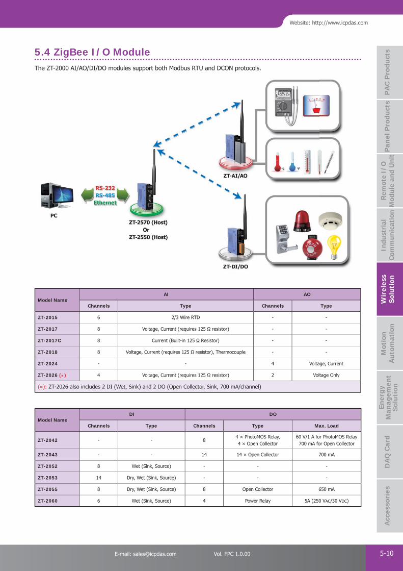
PAC Products
5-10E-mail: [email protected] Vol. FPC 1.0.00
Website: http://www.icpdas.com
PA
C P
rodu
cts
Pan
el P
rodu
cts
Rem
ote
I/O
M
odul
e an
d U
nit
DA
Q C
ard
Indu
stri
al
Com
mun
icat
ion
Wir
eles
s So
luti
onM
otio
n
Au
tom
atio
nA
cces
sori
esEn
ergy
M
anag
emen
tSo
luti
on
Model Name DI DO
Channels Type Channels Type Max. Load
ZT-2042 - - 84 × PhotoMOS Relay, 4 × Open Collector
60 V/1 A for PhotoMOS Relay700 mA for Open Collector
ZT-2043 - - 14 14 × Open Collector 700 mA
ZT-2052 8 Wet (Sink, Source) - - -
ZT-2053 14 Dry, Wet (Sink, Source) - - -
ZT-2055 8 Dry, Wet (Sink, Source) 8 Open Collector 650 mA
ZT-2060 6 Wet (Sink, Source) 4 Power Relay 5A (250 VAC/30 VDC)
5.4 ZigBee I/O Module
Model Name AI AO
Channels Type Channels Type
ZT-2015 6 2/3 Wire RTD - -
ZT-2017 8 Voltage, Current (requires 125 Ω resistor) - -
ZT-2017C 8 Current (Built-in 125 Ω Resistor) - -
ZT-2018 8 Voltage, Current (requires 125 Ω resistor), Thermocouple - -
ZT-2024 - - 4 Voltage, Current
ZT-2026 (*) 4 Voltage, Current (requires 125 Ω resistor) 2 Voltage Only
(*): ZT-2026 also includes 2 DI (Wet, Sink) and 2 DO (Open Collector, Sink, 700 mA/channel)
The ZT-2000 AI/AO/DI/DO modules support both Modbus RTU and DCON protocols./ / / pp p

PAC Products
5-11 ICP DAS CO., LTD. Professional Provider of High Quality Industrial Computer Products and Data Acquisition Systems Vol. FPC 1.0.00
The modules which are named with the same number in ZT-20xx series and ZT-20xx-IOP series have the same I/O specifi cations. In addition, the ZT-20xx-IOP features the following functions to meet the requirements of variety ZigBee applications.
5.5 ZigBee I/O Pair-connection Modules
Model Name Description
ZT-2052-IOP ZigBee I/O pair-connection module with 8 DI
ZT-2053-IOP ZigBee I/O pair-connection module with 14 DI
ZT-2055-IOP ZigBee I/O pair-connection module with 8 DI, 8 DO
ZT-2060-IOP ZigBee I/O pair-connection module with 6 DI, 4 Relay
1.Pair-connecting digital signals with needless of a PC/Controller or other ZigBee coordinator
2.Full hardware confi guration in case creating pair-connection of a ZT-20xx-IOP module and ZT-20xx modules which all have the same number in their module name.
3.Software confi guration in case creating pair-connection of a ZT-20xx-IOP module and ZT-20xx modules which are named with different number.
4.Updates local digital inputs to corresponding remote digital outputs (Peer to multi-peer)
5.Polling remote digital inputs and then updates to corresponding local digital output (Peer to peer)
Model Name Description
4. Updates local digital inputs to corresponding remote digital outputs (Peer to multi-peer)
5. Polling remote digital inputs and then updates to corresponding local digital output (Peer to peer)

PAC Products
5-12E-mail: [email protected] Vol. FPC 1.0.00
Website: http://www.icpdas.com
PA
C P
rodu
cts
Pan
el P
rodu
cts
Rem
ote
I/O
M
odul
e an
d U
nit
DA
Q C
ard
Indu
stri
al
Com
mun
icat
ion
Wir
eles
s So
luti
onM
otio
n
Au
tom
atio
nA
cces
sori
esEn
ergy
M
anag
emen
tSo
luti
on
Model Name GPS
ChannelsSBAS GSM/GPRS Digital Output Interface Protocol
GT-321R-RS232 12WAASEGNOS
- - RS-232 NMEM
GTM-201P-3GWA(Note1)
32WAASEGNOSMSAS
Yes - USB/RS-232 NMEM
I-87211W(Note2)
- 2 Serial bus DCON
I-8213W(Note3)
Yes - Parallel bus NMEM
GPS-721 - 1 RS-232/485 NMEM or DCON
GPS-721-MRTU - 1 RS-232/485 NMEM or Modbus/RTU
Note1: USB driver supported: Win9/2k/XP/7, LinPAC (Linux kernel 2.6)
Note2: Supported controllers and I/O units: XPAC, WinPAC, LinPAC, iPAC, ViewPAC, RU-87P1/2/4/8, USB-87P1/2/4/8
Note3: Supported controllers and I/O units: XPAC, WinPAC, LinPAC, ViewPAC
Support up to 66-channel GPS and NMEM v0183 v3.01
Apply for Automotive, Marine or Personal positioning and navigation
Current time from Satellite
Easy installation
GPS (Global Positioning System) is widely used for driving navigation, geographic monitoring, fleet management and cargo tracking, etc. We also can use GPS for industrial application according to its longitude and latitude value and UTC time. ICP DAS provides various modules for different applications. Some are pure GPS data receivers and some add DO channels. Some even can generate a UTC synchronized 1 PPS (Pulse Per Second) output signal. You can refer the following selection guide in chapter 5 to choose the suitable GPS modules for your application.
● Introduction
● GPS Selection Guide
6. GPS Products
I-87211W
GPS-721GPS-721-MRTU
Advantages & Benefi ts

PAC Products
5-13 ICP DAS CO., LTD. Professional Provider of High Quality Industrial Computer Products and Data Acquisition Systems Vol. FPC 1.0.00
* Note: The remote control distance of Ø 5 mm IRED is 30% longer than Ø 3 mm IRED.
Multiple IR outputs
With RS-232 & RS-485 or Ethernet interface
Support Modbus RTU or Modbus TCP/UDP protocol
Easy integration with HA & BA systems
Infrared (IR) technology is commonly used for remote control of home appliances such as television, air conditioner, AV devices and etc. ICP DAS has developed various IR products to help users to integrate home appliances into control systems. By combination of the PAC, TouchPAD, LC series and regarding products of ICP DAS, users can easily establish their home and building automation systems.
● Introduction
7. Infrared Products
IR-210
IR-310-RM
IR-712A
7.1 IR Learning Remote Module
7.2 IR Controlled Power Relay Module
7.3 Accessories
Model Name IR Output IR Learning Input IR Command Storage Communication interface Communication Protocol
IR-210 6 1 224 RS-232/RS-485 Modbus RTU
IR-712A 2 1 224 RS-232/RS-485 Modbus RTU
IR-712-MTCP 2 1 512 Ethernet Modbus TCP/UDP
* Brand list of appliances (included but not limited to) which can be learned by the IR Learning Remote ModulesURL: http://m2m.icpdas.com/IR-210/IR_device_List_en.png
Model Name Relay Output Contact Rating Comm. interface Comm. Protocol IR Remote Commands IR sensor
IR-310-RM10
(Form C)
5 A @ 220 VAC x 610 A @ 220 VAC x 4
(At 25°C)RS-232 /RS-485 Modbus RTU
Custom: 64 cmdsBuilt-in: 32 cmds
On-board /Receiver cable
Part No. Description
CA-IR-SH2251Single-headed IR emitter cable
(Ø 3 mm IRED, 2.5 m)
CA-IR-SH2252Dual-headed IR emitter cable
(Ø 3 mm IRED, 2.5 m)
CA-IR-SH2251-5Single-headed IR emitter cable
(Ø 5 mm IRED, 2.5 m)
CA-IR-SH2252-5Dual-headed IR emitter cable
(Ø 5 mm IRED, 2.5 m)
Part No. Description
CA-IR-SH2251-360Semi-sphere-headed IR emitter cable
(2.5 m)
CA-IR-SH1251-360Semi-sphere-headed IR receiver
cable (2.5 m)
CA-IR-001Single-headed IR receiver cable
(3 m)
L108E IR Learning Remote Control
Advantages & Benefi ts

Motionnet Solutions P 6-11
● PISO-MN200 / PISO-MN200T - - - - - - - - - - - - - - - - - - - - - - - - - - - - - - P 6-2
● MN-SERVO / MN-SERVO EC Series - - - - - - - - - - - - - - - - - - - - - - - - - - - P 6-3
● MN-2091U / MN-2091U-T - - - - - - - - - - - - - - - - - - - - - - - - - - - - - - - - - P 6-5
● MN-3253/MN-3254/MN-3257/MN-3253T/MN-3254T/MN-3257T - - - - - - - - P 6-7
PAC Solutions - Motion Modules P 6-204
● I-8094 / I-8094F - - - - - - - - - - - - - - - - - - - - - - - - - - - - - - - - - - - - - - P 6-21
● I-8092F-G - - - - - - - - - - - - - - - - - - - - - - - - - - - - - - - - - - - - - - - - - - - P 6-22
PC-based Motion Control Cards P 6-133
● PISO-PS400 - - - - - - - - - - - - - - - - - - - - - - - - - - - - - - - - - - - - - - - - - P 6-15
● PISO-PS410 - - - - - - - - - - - - - - - - - - - - - - - - - - - - - - - - - - - - - - - - - P 6-16
● PISO-PS600 - - - - - - - - - - - - - - - - - - - - - - - - - - - - - - - - - - - - - - - - - P 6-17
● PISO-PS810 - - - - - - - - - - - - - - - - - - - - - - - - - - - - - - - - - - - - - - - - - P 6-18
● PMDK - - - - - - - - - - - - - - - - - - - - - - - - - - - - - - - - - - - - - - - - - - - - - P 6-19
Ethernet Motion Control Solutions P 6-92
● ET-M8194H - - - - - - - - - - - - - - - - - - - - - - - - - - - - - - - - - - - - - - - - - - P 6-11
Features of Motion Function P 6-235
Motion AutomationMotion Automation 6

PAC Products
6-1 ICP DAS CO., LTD. Professional Provider of High Quality Industrial Computer Products and Data Acquisition Systems Vol. FPC 1.0.00
1. Motionnet Solutions
Motionnet is a high-speed serial communication system that includes a Master card and Slave modules. ICP DAS provides two categories of Slaves: the fi rst is used for Digital I/O, and the other is used for motion control. There are 3 main types of digital I/O modules: 32-ch Input, 32-ch Output and 16-ch Input/Output. Using these Slave devices, customers’ actuators/sensors can easily be directly connected. Motion control modules can be used together with either a Servo motor or a Stepping motor from a variety of vendors.
Motionnet communication between a Master and the Slaves is based on a proprietary RS-485 technology (Multi-drop, Half-duplex) and provides the advantage of reduced wiring requirements together with the capability of long-distance and high-speed communication. Data transfer for the I/O modules is cyclical and time deterministic, so can be widely used for industrial automation applications.
Communication Speed: Max. 20 Mbps
Communication Distance: Max. 100 m
Controllable Modules: 64 modules per line
Data Transfer Rate: 15.1 μsec/module (each module provides 32 I/O points)
2048 points in 0.97 ms (when 64 modules are connected)
Remote Motion Solutions Product List:
Motionnet Solutions
PISO-MN200(T) PCI bus, Dual-line Motionnet Control Master Card
MN-SERVO-xxx(-EC) Series Distributed Motionnet Single-axis Motion Control Modules
MN-2091U(-T) Distributed Motionnet Single-axis Universal Motion Control Module
MN-3254/3253/3257(T) Distributed Motionnet Isolated DI/DO Modules
● Introduction
Features
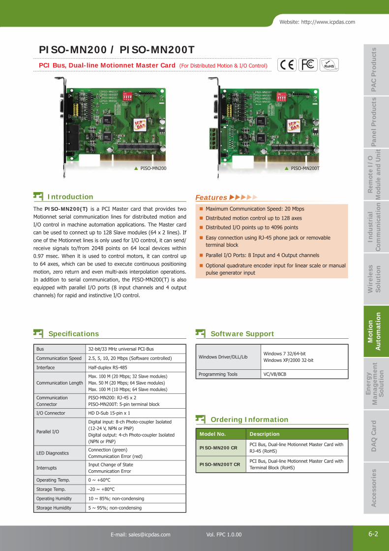
PAC Products
6-2E-mail: [email protected] Vol. FPC 1.0.00
Website: http://www.icpdas.com
PA
C P
rodu
cts
Pan
el P
rodu
cts
Rem
ote
I/O
M
odul
e an
d U
nit
DA
Q C
ard
Indu
stri
al
Com
mun
icat
ion
Wir
eles
s So
luti
onM
otio
n
Au
tom
atio
nA
cces
sori
esEn
ergy
M
anag
emen
tSo
luti
on
Bus 32-bit/33 MHz universal PCI-Bus
Communication Speed 2.5, 5, 10, 20 Mbps (Software controlled)
Interface Half-duplex RS-485
Communication LengthMax. 100 M (20 Mbps; 32 Slave modules)Max. 50 M (20 Mbps; 64 Slave modules)Max. 100 M (10 Mbps; 64 Slave modules)
Communication Connector
PISO-MN200: RJ-45 x 2PISO-MN200T: 5-pin terminal block
I/O Connector HD D-Sub 15-pin x 1
Parallel I/O
Digital input: 8-ch Photo-coupler Isolated (12-24 V, NPN or PNP)Digital output: 4-ch Photo-coupler Isolated (NPN or PNP)
LED Diagnostics Connection (green) Communication Error (red)
InterruptsInput Change of StateCommunication Error
Operating Temp. 0 ~ +60°C
Storage Temp. -20 ~ +80°C
Operating Humidity 10 ~ 85%; non-condensing
Storage Humidity 5 ~ 95%; non-condensing
The PISO-MN200(T) is a PCI Master card that provides two Motionnet serial communication lines for distributed motion and I/O control in machine automation applications. The Master card can be used to connect up to 128 Slave modules (64 x 2 lines). If one of the Motionnet lines is only used for I/O control, it can send/receive signals to/from 2048 points on 64 local devices within 0.97 msec. When it is used to control motors, it can control up to 64 axes, which can be used to execute continuous positioning motion, zero return and even multi-axis interpolation operations. In addition to serial communication, the PISO-MN200(T) is also equipped with parallel I/O ports (8 input channels and 4 output channels) for rapid and instinctive I/O control.
Windows Driver/DLL/LibWindows 7 32/64-bit Windows XP/2000 32-bit
Programming Tools VC/VB/BCB
Model No. Description
PISO-MN200 CRPCI Bus, Dual-line Motionnet Master Card with RJ-45 (RoHS)
PISO-MN200T CRPCI Bus, Dual-line Motionnet Master Card with Terminal Block (RoHS)
Ordering Information
Software SupportSpecifi cations
Introduction
PISO-MN200 / PISO-MN200TPCI Bus, Dual-line Motionnet Master Card (For Distributed Motion & I/O Control)
PISO-MN200 PISO-MN200T
Features Maximum Communication Speed: 20 Mbps
Distributed motion control up to 128 axes
Distributed I/O points up to 4096 points
Easy connection using RJ-45 phone jack or removable terminal block
Parallel I/O Ports: 8 Input and 4 Output channels
Optional quadrature encoder input for linear scale or manual pulse generator input
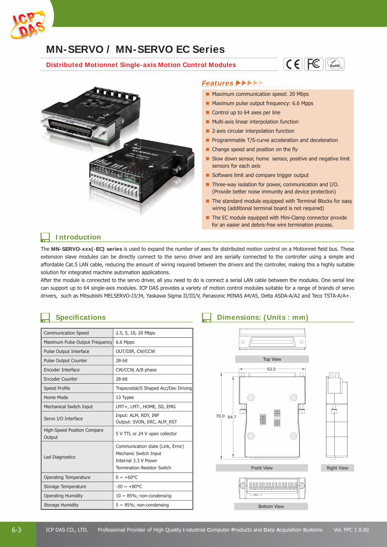
PAC Products
6-3 ICP DAS CO., LTD. Professional Provider of High Quality Industrial Computer Products and Data Acquisition Systems Vol. FPC 1.0.00
64.770.0
53.0
The MN-SERVO-xxx(-EC) series is used to expand the number of axes for distributed motion control on a Motionnet fi eld bus. These extension slave modules can be directly connect to the servo driver and are serially connected to the controller using a simple and affordable Cat.5 LAN cable, reducing the amount of wiring required between the drivers and the controller, making this a highly suitable solution for integrated machine automation applications.After the module is connected to the servo driver, all you need to do is connect a serial LAN cable between the modules. One serial line can support up to 64 single-axis modules. ICP DAS provides a variety of motion control modules suitable for a range of brands of servo drivers, such as Mitsubishi MELSERVO-J3/J4, Yaskawa Sigma II/III/V, Panasonic MINAS A4/A5, Delta ASDA-A/A2 and Teco TSTA-A/A+.
Communication Speed 2.5, 5, 10, 20 Mbps
Maximum Pulse Output Frequency 6.6 Mpps
Pulse Output Interface OUT/DIR, CW/CCW
Pulse Output Counter 28-bit
Encoder Interface CW/CCW, A/B phase
Encoder Counter 28-bit
Speed Profi le Trapezoidal/S Shaped Acc/Dec Driving
Home Mode 13 Types
Mechanical Switch Input LMT+, LMT-, HOME, SD, EMG
Servo I/O InterfaceInput: ALM, RDY, INPOutput: SVON, ERC, ALM_RST
High-Speed Position Compare
Output5 V TTL or 24 V open collector
Led Diagnostics
Communication state (Link, Error)
Mechanic Switch Input
Internal 3.3 V Power
Termination Resistor Switch
Operating Temperature 0 ~ +60°C
Storage Temperature -20 ~ +80°C
Operating Humidity 10 ~ 85%; non-condensing
Storage Humidity 5 ~ 95%; non-condensing
MN-SERVO / MN-SERVO EC SeriesDistributed Motionnet Single-axis Motion Control Modules
Specifi cations
Introduction
Dimensions: (Units : mm)
Features Maximum communication speed: 20 Mbps
Maximum pulse output frequency: 6.6 Mpps
Control up to 64 axes per line
Multi-axis linear interpolation function
2-axis circular interpolation function
Programmable T/S-curve acceleration and deceleration
Change speed and position on the fl y
Slow down sensor, home sensor, positive and negative limit sensors for each axis
Software limit and compare trigger output
Three-way isolation for power, communication and I/O. (Provide better noise immunity and device protection)
The standard module equipped with Terminal Blocks for easy wiring (additional terminal board is not required)
The EC module equipped with Mini-Clamp connector provide for an easier and debris-free wire termination process.
Top View
Front View Right View
Bottom View

PAC Products
6-4E-mail: [email protected] Vol. FPC 1.0.00
Website: http://www.icpdas.com
PA
C P
rodu
cts
Pan
el P
rodu
cts
Rem
ote
I/O
M
odul
e an
d U
nit
DA
Q C
ard
Indu
stri
al
Com
mun
icat
ion
Wir
eles
s So
luti
onM
otio
n
Au
tom
atio
nA
cces
sori
esEn
ergy
M
anag
emen
tSo
luti
on
No. Name DescriptionSignal
Direction
1 ~ 2 Data+ Serial communication data+ Both
3 ~ 4 Data- Serial communication data- Both
5 FG Frame ground None
6 ~ 7 EGND External ground Input
8 ~ 9 E24V External power 24V Input
10 CMP High speed position compare Output
11 EMG Emergency stop Input
12 SD Slowdown Input
13 LMT+ Positive end limit Input
14 HOME Home position Input
15 LMT- Negative end limit Input
Wire Range: 28~20 AWGWire Strip Length: 10 mm
321
MC1 MC2 MC3 MC4 MC5 MC6
321
Connector No. Name DescriptionSignal
Direction
MC1
3 Data- Serial communication data- Both
2 Data+ Serial communication data+ Both
1 F.G. Frame ground None
MC2
3 Data- Serial communication data- Both
2 Data+ Serial communication data+ Both
1 F.G. Frame ground None
MC3
3 E24V External power 24V Input
2 EGND External ground Input
1 F.G. Frame ground None
MC4
3 E24V External power 24V Input
2 EGND External ground Input
1 F.G. Frame ground None
MC5
3 CMP High speed position compare Output
2 EMG Emergency stop Input
1 SD Slowdown Input
MC6
3 LMT+ Positive end limit Input
2 HOME Home position Input
1 LMT- Negative end limit Input
Mini Clamp Wiremount Plug Applicable Wire
ICP DAS Part No. Cover Color 3M Part No. AWG No. Cross-sectional Area (mm2) Finished External Diameter Φ (mm)
4PKD1O0000001 Gray 37103-2206-000FL 20 – 22 0.3 – 0.5 1.6 – 2.0
4PKD1O0000002 Red 37103-3101-000FL 24 – 26 0.14 – 0.3 0.8 – 1.0
4PKD1O0000003 Orange 37103-3163-000FL 24 – 26 0.14 – 0.3 1.2 – 1.6
4PKD1O0000001 4PKD1O0000002 4PKD1O0000003
Gray Mini Clamp Wiremount Plug
Red Mini Clamp Wiremount Plug
Orange Mini Clamp Wiremount Plug
Part No. Picture Description Part No. Picture Description
4POPP-003F Pink Cord-End Terminal 4POPP-003G Turquoise Cord-End Terminal
Model No. Description
MN-SERVO-MJ3 CRMN-SERVO-MJ3-EC CR
Distributed Motionnet Single-axis Motion Control Module with Spring Type Terminal Blocks (EC: with e-CON Mini-Clamp connector ) for Mitsubishi MELSERVO-J3/J4 (RoHS)
MN-SERVO-PA4 CRMN-SERVO-PA4-EC CR
Distributed Motionnet Single-axis Motion Control Module with Spring Type Terminal Blocks (EC: with e-CON Mini-Clamp connector )for Panasonic MINAS A4 (RoHS)
MN-SERVO-YSV CRMN-SERVO-YSV-EC CR
Distributed Motionnet Single-axis Motion Control Module with Spring Type Terminal Blocks (EC: with e-CON Mini-Clamp connector )for Yaskawa Sigma II/III/V (RoHS)
MN-SERVO-DAA CRMN-SERVO-DAA-EC CR
Distributed Motionnet Single-axis Motion Control Module with Spring Type Terminal Blocks (EC: with e-CON Mini-Clamp connector )for Delta ASDA-A/A2 (RoHS)
MN-SERVO-TTA CRMN-SERVO-TTA-EC CR
Distributed Motionnet Single-axis Motion Control Module with Spring Type Terminal Blocks (EC: with e-CON Mini-Clamp connector )for Teco TSTA-A/A+ (RoHS)
Pin Assignments Pin Assignments of -EC module
Ordering Information/Accessories
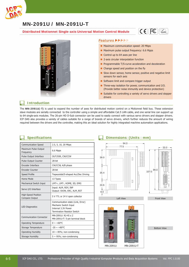
PAC Products
6-5 ICP DAS CO., LTD. Professional Provider of High Quality Industrial Computer Products and Data Acquisition Systems Vol. FPC 1.0.00
94.0
33.0
107.099.0
77.5
35.4
39.0
24.6
8.0
Communication Speed 2.5, 5, 10, 20 Mbps
Maximum Pulse Output Frequency
6.6 Mpps
Pulse Output Interface OUT/DIR, CW/CCW
Pulse Output Counter 28-bit
Encoder Interface CW/CCW, A/B phase
Encoder Counter 28-bit
Speed Profi le Trapezoidal/S-shaped Acc/Dec Driving
Home Mode 13 Types
Mechanical Switch Input LMT+, LMT-, HOME, SD, EMG
Servo I/O InterfaceInput: ALM, RDY, INPOutput: SVON, ERC, ALM_RST
High-Speed Position Compare Output
5 V TTL or 24 V open collector
LED Diagnostics
Communication state (Link, Error)Mechanic Switch InputInternal 3.3V PowerTermination Resistor Switch
Communication ConnectorMN-2091U: RJ-45 x 2MN-2091U-T: 5-pin terminal block
Operating Temperature 0 ~ +60°C
Storage Temperature -20 ~ +80°C
Operating Humidity 10 ~ 85%; non-condensing
Storage Humidity 5 ~ 95%; non-condensing
MN-2091U MN-2091U-T
MN-2091U / MN-2091U-TDistributed Motionnet Single-axis Universal Motion Control Module
Features Maximum communication speed: 20 Mbps
Maximum pulse output frequency: 6.6 Mpps
Control up to 64 axes per line
2-axis circular interpolation function
Programmable T/S-curve acceleration and deceleration
Change speed and position on the fl y
Slow down sensor, home sensor, positive and negative limit sensors for each axis
Software limit and compare trigger output
Three-way isolation for power, communication and I/O. (Provide better noise immunity and device protection)
Suitable for controlling a variety of servo drivers and stepper drivers
The MN-2091U(-T) is used to expand the number of axes for distributed motion control on a Motionnet fi eld bus. These extension slave modules are serially connected to the controller using a simple and affordable Cat.5 LAN cable, and one serial line can support up to 64 single-axis modules. The 26-pin HD D-Sub connector can be used to easily connect with various servo drivers and stepper drivers. ICP DAS also provides a variety of cables suitable for a range of brands of servo drivers, which further reduces the amount of wiring required between the drivers and the controller, making this an ideal solution for highly integrated machine automation applications.
Introduction
Specifi cations Dimensions: (Units : mm)
Front ViewLeft View
Bottom View

PAC Products
6-6E-mail: [email protected] Vol. FPC 1.0.00
Website: http://www.icpdas.com
PA
C P
rodu
cts
Pan
el P
rodu
cts
Rem
ote
I/O
M
odul
e an
d U
nit
DA
Q C
ard
Indu
stri
al
Com
mun
icat
ion
Wir
eles
s So
luti
onM
otio
n
Au
tom
atio
nA
cces
sori
esEn
ergy
M
anag
emen
tSo
luti
on
Pin No. Pin Name Description I/O
Defi ne. Pin No. Pin Name Description I/O Defi ne.
CNIO1B (Left) Pin Assignments CNIO1A (Right) Pin Assignments
1 HOME Home position Input 1 LMT- Negative end limit Input
2 SD Slowdown Input 2 LMT+ Positive end limit Input
3 EGND External ground Input 3 EMG Emergency stop Input
4 5V_o Internal 5 V power derived from 24 V supply Output 4 CMP High-speed position
compare Output
5 AGND Optional analog ground, no internal connection
Connect to CM1 only 5 RSV Reserved signal
(no internal connection)Connect to CM1 only
6 FGND Frame ground None 6 FGND Frame ground None
7 ~ 8 EGND External ground Input 7 ~ 8 EGND External ground Input
9 ~ 10 E24V External power 24 V Input 9 ~ 10 E24V External power 24 V Input
Pin No. Pin Name Description I/O
Defi ne.
1 SRV_ON Servo On Output
2 INP In Position Input
3 ERC Error Counter Clear Output
4 RDY Servo Ready Input
5 P- Forward rotation pulse train (differential line driver)
Output
6 P+ Output
7 A-Encoder A-phase pulse
Input
8 A+ Input
9 N.C. No internal connection N.C.
10 RESET Alarm Reset Output
11 ALARM Servo Alarm Input
12 E24V External power 24V Input
13 EGND External ground Input
14 N.C. No internal connection N.C.
Pin No. Pin Name Description I/O
Defi ne.
15 AGND Optional analog ground(no internal connection)
Connect to CNIO1 only
16 B-Encoder B-phase pulse
Input
17 B+ Input
18 N.C. No internal connection N.C.
19 EMG Emergency stop Input
20 RSV Reserved signal (no internal connection)
Connect to CNIO1 only
21 EGND External ground Input
22 EGND External ground Input
23 N- Forward rotation pulse train (differential line driver)
Output
24 N+ Output
25 Z-Encoder Z-phase pulse
Input
26 Z+ Input
CNIO
1
1 19
1826
CM1
Model No. Description
MN-2091U CR Distributed Motionnet Single-axis Universal Motion Control Module with RJ-45 Connector (RoHS)
MN-2091U-T CR Distributed Motionnet Single-axis Universal Motion Control Module with Terminal Block (RoHS)
Model No. Description
CA-PC26M 26-pin HD D-Sub solder cup Male connector with plastic cover
CA-26-DAB2-15/30/50 26-pin HD D-Sub Male cable for Delta B2 servo amplifi er, 1.5/3/5 M (for ASDA-B2 series)
CA-26-FFW-15/30/50 26-pin HD D-Sub Male cable for Fuji servo amplifi er, 1.5/3/5 M (for FALDIC-W and ALPHA5 Smart series)
CA-26-MJ3-15/30/50 26-pin HD D-Sub Male cable for Mitsubishi servo amplifi er, 1.5/3/5 M (for MELSERVO-J3/J4 series)
CA-26-YSV-15/30/50 26-pin HD D-Sub Male cable for Yaskawa servo amplifi er, 1.5/3/5 M (for Sigma II/III/V series)
CA-26-PA4-15/30/50 26-pin HD D-Sub Male cable for Panasonic servo amplifi er, 1.5/3/5 M (for MINAS A4/A5 series)
CA-26-DAA2-15/30/50 26-pin HD D-Sub Male cable for Delta A2 servo amplifi er, 1.5/3/5 M (for ASDA-A2 series)
CA-26-TTA-15/30/50 26-pin HD D-Sub Male cable for Teco servo amplifi er, 1.5/3/5 M (for TSTA-A/A+ series)
Pin Assignments
Accessories
Ordering Information
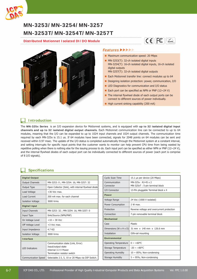
PAC Products
6-7 ICP DAS CO., LTD. Professional Provider of High Quality Industrial Computer Products and Data Acquisition Systems Vol. FPC 1.0.00
Digital Output
Output Channels MN-3253: 0 ; MN-3254: 16; MN-3257: 32
Output Type Open Collector (Sink), with internal fl ywheel diode
Load Voltage +30 VDC max.
Load Current 200 mA max. for each channel
Isolation Voltage 3000 Vrms
Digital Input
Input Channels MN-3253: 32 ; MN-3254: 16; MN-3257: 0
Input Type Sink/Source (NPN/PNP)
On Voltage Level +10 ~ 30 VDC
Off Voltage Level +3 VDC max.
Input Impedance 4.7 KΩ
Isolation Voltage 3000 Vrms
Interface
LED Indicators
Communication state (Link, Error)Input/output stateInternal 3.3 V PowerTermination resistor switch
Communication Speed Selectable 2.5, 5, 10 or 20 Mbps via DIP Switch.
Cyclic Scan Time 15.1 μs per device (20 Mbps)
Communication Connector
MN-325x : RJ-45 x 2MN-325xT : 5-pin terminal block
I/O Connector 13-Pin pluggable Terminal block x 4
Power
Voltage Range 24 VDC (1000 V isolated)
Power Consumption 2 W max.
Protection Reverse voltage and overcurrent protection
Connection 7-pin removable terminal block
Mechanical
Case Plastic
Dimensions (W x H x D) 31 mm x 140 mm x 126.6 mm
Installation DIN-rail mounting
Environmental
Operating Temperature 0 ~ +60°C
Storage Temperature -20 ~ +80°C
Operating Humidity 10 ~ 85%; Non-condensing
Storage Humidity 5 ~ 95%; Non-condensing
MN-3253/MN-3254/MN-3257MN-3253T/MN-3254T/MN-3257TDistributed Motionnet Isolated DI/DO Module
Features Maximum communication speed: 20 Mbps
MN-3253(T): 32-ch isolated digital inputs MN-3254(T): 16-ch isolated digital inputs, 16-ch isolated digital outputs MN-3257(T): 32-ch isolated digital outputs
Each Motionnet transfer line: connect modules up to 64
Designing isolation protection: power, communication, I/O
LED Diagnostics for communication and I/O status
Each port can be specifi ed as NPN or PNP (12~24 V)
The internal fl ywheel diode of each output ports can be connect to different sources of power individually.
High current sinking capability (200 mA)
The MN-325x Series is an I/O expansion device for Motionnet systems, and is equipped with up to 32 isolated digital input channels and up to 32 isolated digital output channels. Each Motionnet communication line can be connected to up to 64 modules, meaning that the I/O can be expanded to up to 1024 input channels and 1024 output channels. The communication time required by each MN-325x is 15.1 us. If 64 modules have been connected, signals for 2048 points on 64 modules can be sent and received within 0.97 msec. The update of the I/O status is completed automatically through the Motionnet system at a constant interval, and setting interrupts for specifi c input points that the customer wants to monitor can help prevent CPU time from being wasted by repetitive polling when there is nothing else for the issuing process to do. Each input port can be specifi ed as either NPN or PNP (12~24 V), and the internal fl ywheel diodes of each output port can be individually connected to different sources of power (each port is comprise of 8 I/O signals).
Introduction
Specifi cations

PAC Products
6-8E-mail: [email protected] Vol. FPC 1.0.00
Website: http://www.icpdas.com
PA
C P
rodu
cts
Pan
el P
rodu
cts
Rem
ote
I/O
M
odul
e an
d U
nit
DA
Q C
ard
Indu
stri
al
Com
mun
icat
ion
Wir
eles
s So
luti
onM
otio
n
Au
tom
atio
nA
cces
sori
esEn
ergy
M
anag
emen
tSo
luti
on
147.0
81.7
50.4
112.
112
6.6
31.0
140.0
147.
0
140.
0
NO. Pin Defi ne. Specifi cations I/O Defi ne.
CN1 Pin Assignments
1 FG Frame Ground -
2 ~ 4 EGND External Ground Input
5 ~ 7 E24V External 24 V (+) Input
CN2A (Right) Pin Assignments
1 ~ 2 E24V External 24 V (+) Connect to CN1
3 DICOM1 Common terminal of DI00 ~ DI07 Input
4 ~ 11 DI00~DI07 Digital input channels 00~07 Input
12~13 EGND External Ground Connect to CN1
CN2B (Left) Pin Assignments
1 ~ 2 E24V External 24 V (+) Connect to CN1
3 DICOM2 Common terminal of DI08 ~ DI15 Input
4 ~ 11 DI08~DI15 Digital input channels 08~15 Input
12~13 EGND External Ground Connect to CN1
CN3A (Right) Pin Assignments
1 ~ 2 E24V External 24 V (+) Connect to CN1
3 DOCOM1 Common Anode for Flywheel Diodes of DO00 ~ DO07 Input
4 ~ 11 DO00~DO07 Digital output channels 00~07 Output
12~13 EGND External Ground Connect to CN1
CN3B (Left) Pin Assignments
1 ~ 2 E24V External 24 V (+) Connect to CN1
3 DOCOM2 Common Anode for Flywheel Diodes of DO08 ~ DO15 Input
4 ~ 11 DO08~DO15 Digital output channels 08~15 Output
12~13 EGND External Ground connect to CN1
Model No. Description
MN-3253 CRMN-3253T CR
Distributed Motionnet 32-ch Isolated DI Module (with RJ-45 Connector; T: with Terminal Block) (RoHS)
MN-3254 CRMN-3254T CR
Distributed Motionnet 16-ch Isolated DI, 16-ch Isolated DO Module (with RJ-45 Connector; T: with Terminal Block) (RoHS)
MN-3257 CRMN-3257T CR
Distributed Motionnet 32-ch Isolated DO Module (with RJ-45 Connector; T: with Terminal Block) (RoHS)
Pin Assignments of MN-3254(T)
Ordering Information
Dimensions: (Units : mm)
Top ViewFront View Right View
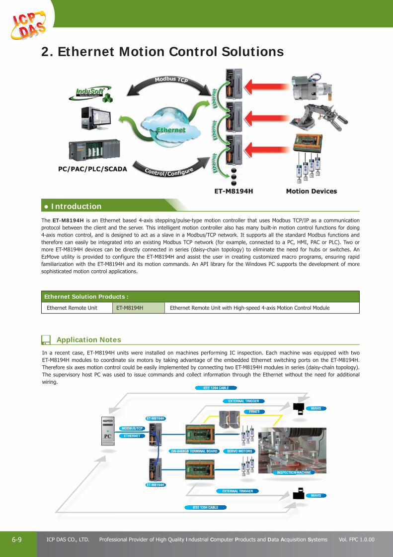
PAC Products
6-9 ICP DAS CO., LTD. Professional Provider of High Quality Industrial Computer Products and Data Acquisition Systems Vol. FPC 1.0.00
In a recent case, ET-M8194H units were installed on machines performing IC inspection. Each machine was equipped with two ET-M8194H modules to coordinate six motors by taking advantage of the embedded Ethernet switching ports on the ET-M8194H. Therefore six axes motion control could be easily implemented by connecting two ET-M8194H modules in series (daisy-chain topology). The supervisory host PC was used to issue commands and collect information through the Ethernet without the need for additional wiring.
IEEE 1394 CABLE
IEEE 1394 CABLE
MAVISFRNET
ET-M8194H
ET-M8194H
MODBUS/TCP
ETHERNET
MAVIS
EXTERNAL TRIGGER
EXTERNAL TRIGGER
INSPECTION MACHINE
SERVO MOTORSDN-8468GB TERMINAL BOARD
IEEE 1394 CABLE
FRNET
EXTERNAL TRIGGER
INSPECTION
SERVO MOTORSB TERMINAL BOARD
Ethernet Solution Products :
Ethernet Remote Unit ET-M8194H Ethernet Remote Unit with High-speed 4-axis Motion Control Module
2. Ethernet Motion Control Solutions
The ET-M8194H is an Ethernet based 4-axis stepping/pulse-type motion controller that uses Modbus TCP/IP as a communication protocol between the client and the server. This intelligent motion controller also has many built-in motion control functions for doing 4-axis motion control, and is designed to act as a slave in a Modbus/TCP network. It supports all the standard Modbus functions and therefore can easily be integrated into an existing Modbus TCP network (for example, connected to a PC, HMI, PAC or PLC). Two or more ET-M8194H devices can be directly connected in series (daisy-chain topology) to eliminate the need for hubs or switches. An EzMove utility is provided to configure the ET-M8194H and assist the user in creating customized macro programs, ensuring rapid familiarization with the ET-M8194H and its motion commands. An API library for the Windows PC supports the development of more sophisticated motion control applications.
● Introduction
Application Notes
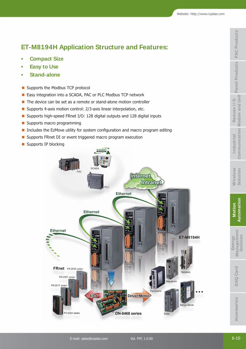
PAC Products
6-10E-mail: [email protected] Vol. FPC 1.0.00
Website: http://www.icpdas.com
PA
C P
rodu
cts
Pan
el P
rodu
cts
Rem
ote
I/O
M
odul
e an
d U
nit
DA
Q C
ard
Indu
stri
al
Com
mun
icat
ion
Wir
eles
s So
luti
onM
otio
n
Au
tom
atio
nA
cces
sori
esEn
ergy
M
anag
emen
tSo
luti
on
Supports the Modbus TCP protocol
Easy integration into a SCADA, PAC or PLC Modbus TCP network
The device can be set as a remote or stand-alone motion controller
Supports 4-axis motion control: 2/3-axis linear interpolation, etc.
Supports high-speed FRnet I/O: 128 digital outputs and 128 digital inputs
Supports macro programming
Includes the EzMove utility for system confi guration and macro program editing
Supports FRnet DI or event triggered macro program execution
Supports IP blocking
ET-M8194H Application Structure and Features:
• Compact Size • Easy to Use • Stand-alone
ts FRnet DI or event triggered macro program execution
ts IP blockingg

PAC Products
6-11 ICP DAS CO., LTD. Professional Provider of High Quality Industrial Computer Products and Data Acquisition Systems Vol. FPC 1.0.00
EzMove is a configuration utility developed by ICP DAS for the ET-M8194H controller. It is intended to perform motion control tasks and movement test on equipment without the need to first create customized applications. As the EzMove Utility is a Modbus client, it can be used to create and edit Macro Programs (MP), which can then be uploaded to the ET-M8194H. The EzMove Utility can also display and plot position/velocity of all four axes as well as display Modbus TCP messages for easy reference.
EzMove Utility
The ET-M8194H API Library is composed of nine groups of functions, which can be utilized to edit Macro Programs (MP) and send Modbus TCP commands required to control or confi gure the I-8094H. The library provides users with the ability to simultaneously control a large number of ET-M8194H from the PC. DLL and libraries for the following development environments are provided: Visual C++ BCB 5.0, 6.0 C#, VB.NET Visual Basic 6.0
API Library
The ET-M8194H is a new product from ICP DAS that can be used to implement remote control functionality via the Ethernet and includes an I-8094H module (a 4-axis stepping/pulse-type servo motor control module with an embedded CPU) and an Ethernet communication interface. The intelligent ET-M8194H can provide users with the ability to develop a wide range of remote motion control applications, and can be integrated in any system where the host platform is built on the Modbus TCP protocol (for example: PC, PAC or PLC). In addition, implementing a multi-station, multi-axis motion control solution can easily be achieved by cascading several ET-M8194H devices using Ethernet cables, either with or without Ethernet switches. ICP DAS also provides the EzMove Utility and an API Library that can be used to confi gure the ET-M8194H and to rapidly develop customized control applications.
Introduction
SoftwareHardware
ET-M8194HEthernet Remote Unit with High-speed 4-axis Motion Control Module
Features Remote control via Modbus TCP
Can be controlled using SCADA, PAC or PLC, etc.
Can be integrated into multi-station, multi-axis applications
4-axis motion control capability
2/3-axis Linear Interpolation Function
2-axis Circular Interpolation Function
Programmable Automatic Homing function
EzMove Utility for confi guration and macro programming
Test motion functions via EzMove without compilation
API Library for rapid development of applications
Easy wiring for multi-station applications
IP_lock function for remote control security
ti
Power and RS-232 LED
Power and RS-232 wring
I-8094H Status LED
I-8094H Signal Communication Port
Boot Mode Dip Switch
Ethernet Port
Ethernet Connection andModule Detection LED
ET-M8194H Interface Functions
PAC Products
6-12E-mail: [email protected] Vol. FPC 1.0.00
Website: http://www.icpdas.com
PA
C P
rodu
cts
Pan
el P
rodu
cts
Rem
ote
I/O
M
odul
e an
d U
nit
DA
Q C
ard
Indu
stri
al
Com
mun
icat
ion
Wir
eles
s So
luti
onM
otio
n
Au
tom
atio
nA
cces
sori
esEn
ergy
M
anag
emen
tSo
luti
on
X-Y-Z Table
Fix-Pitch Stamping Machine
Transfer Machine
Spinner
Loader/Unloader
Interpolation FunctionsLinear Interpolation (Interpolation Speed: 4 Mpps): 32-bit max. for any single command Circular Interpolation (Interpolation Speed: 4 Mpps): 32-bit max. for any single commandContinuous Interpolation (Interpolation Speed: 2 Mpps): Yes
Drive Speed Curve
Maximum Drive Speed: 4 Mpps Constant Speed DrivingTrapezoidal Acc/Dec Driving Asymmetrical Trapezoidal DrivingS-curve Acc/Dec DrivingAsymmetrical S-curve Driving
Position Control
Logic Position Counter/Bit Length for output pulse: 32-bit Real Position Counter/Bit Length for output pulse: 32-bit Position Compare Register Number/Axis: 2Software Limit Position Counter Variable Ring
Auto-Home Search Individual confi guration (4-step) for each axis including irregular operation handling
Synchronous Action 10 activation factors (provocatives or events) and 14 actions
External Signal for DrivingFixed/Continuous Pulse OutputManual Pulse
Other FunctionsDrive Speed/Output Pulse Number Change during Driving Triangle Form Prevention of Speed Curve
Servo Motor SignalServo Ready and Alarm Input Signals/AxisServo Enable Output/Axis
Other Input SignalsIN0 (Near Home), IN1 (Home), IN2 (Z-phase), IN3/Axis Emergency Signal
Input Signal Integral Type Filter Filter Time Constant: 2 ~ 16 ms, 8 stages
Environmental
Operating Temperature: -20 ~ +75°CStorage Temperature: -30 ~ +85°C Operating Humidity: 10 ~ 85% RH, non-condensingStorage Humidity: 5 ~ 90% RH, non-condensing
FRnet Interface
Max. 128 DI and 128 DO channels Hardware auto-scan I/O every 0.72 ms Two-wire Serial Bus to reduce wiring needsMax. communication distance: 100 M A wide range of FRnet I/O terminal boards and modules are available
Model No. Description
ET-M8194H Ethernet Remote Automation Unit with High-speed 4-axis Motion Control Module
DN-8468UB Photo-isolated Universal Snap-on Wiring Terminal Board
DN-8468GB Photo-isolated General Purpose Wiring Terminal Board
DN-8468MB Photo-isolated Snap-on Wiring Terminal Board for Mitsubishi MELSERVO-J2 Servo Amplifi er
DN-8468PB Photo-isolated Snap-on Wiring Terminal Board for Panasonic MINAS A4/A5 Servo Amplifi er
DN-8468YB Photo-isolated Snap-on Wiring Terminal Board for Yaskawa Sigma II/III/V Servo Amplifi er
DN-8468DB Photo-isolated Snap-on Wiring Terminal Board for Delta ASDA-A Servo Amplifi er
DN-8468FB Photo-isolated Snap-on Wiring Terminal Board for Fuji FALDIC-W Servo Amplifi er
CA-SCSI15-H / CA-SCSI30-H / CA-SCSI50-H 68-pin SCSI-II Connector Cable; Length 1.5 M / 3.0 M / 5.0 M
Specifi cations
Applications
Ordering Information/Accessories

PAC Products
6-13 ICP DAS CO., LTD. Professional Provider of High Quality Industrial Computer Products and Data Acquisition Systems Vol. FPC 1.0.00
3. PC-based Motion Control Cards
PC-based Solutions
As a leading automation solutions provider, ICP DAS not only provides PAC solutions, but also develops PC-based solutions for machine automation applications, including the PCI bus motion control cards and the ISA bus motion control cards series.
In addition, we also offer a variety of quick-connect terminal blocks for a range of servo motors, including Mitsubishi, Panasonic, Yaskawa, Delta, etc., which helps customers quickly implement the installation and reduce the potential for using the incorrect wiring.
● Introduction
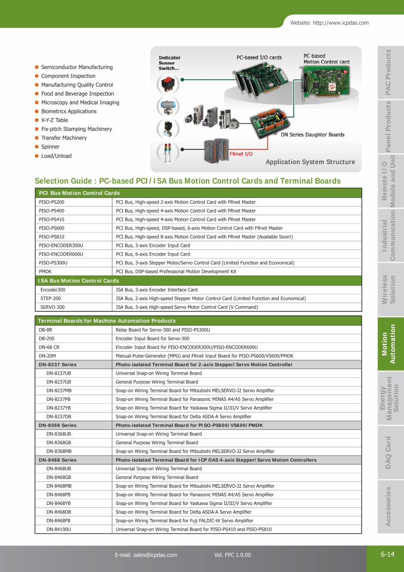
PAC Products
6-14E-mail: [email protected] Vol. FPC 1.0.00
Website: http://www.icpdas.com
PA
C P
rodu
cts
Pan
el P
rodu
cts
Rem
ote
I/O
M
odul
e an
d U
nit
DA
Q C
ard
Indu
stri
al
Com
mun
icat
ion
Wir
eles
s So
luti
onM
otio
n
Au
tom
atio
nA
cces
sori
esEn
ergy
M
anag
emen
tSo
luti
on
PCI Bus Motion Control Cards
PISO-PS200 PCI Bus, High-speed 2-axis Motion Control Card with FRnet Master
PISO-PS400 PCI Bus, High-speed 4-axis Motion Control Card with FRnet Master
PISO-PS410 PCI Bus, High-speed 4-axis Motion Control Card with FRnet Master
PISO-PS600 PCI Bus, High-speed, DSP-based, 6-axis Motion Control Card with FRnet Master
PISO-PS810 PCI Bus, High-speed 8-axis Motion Control Card with FRnet Master (Available Soon!)
PISO-ENCODER300U PCI Bus, 3-axis Encoder Input Card
PISO-ENCODER600U PCI Bus, 6-axis Encoder Input Card
PISO-PS300U PCI Bus, 3-axis Stepper Motor/Servo Control Card (Limited Function and Economical)
PMDK PCI Bus, DSP-based Professional Motion Development Kit
ISA Bus Motion Control Cards
Encoder300 ISA Bus, 3-axis Encoder Interface Card
STEP-200 ISA Bus, 2-axis High-speed Stepper Motor Control Card (Limited Function and Economical)
SERVO-300 ISA Bus, 3-axis High-speed Servo Motor Control Card (V Command)
Semiconductor Manufacturing
Component Inspection
Manufacturing Quality Control
Food and Beverage Inspection
Microscopy and Medical Imaging
Biometrics Applications
X-Y-Z Table
Fix-pitch Stamping Machinery
Transfer Machinery
Spinner
Load/Unload
Selection Guide : PC-based PCI/ISA Bus Motion Control Cards and Terminal Boards
Terminal Boards for Machine Automation Products
DB-8R Relay Board for Servo-300 and PISO-PS300U
DB-200 Encoder Input Board for Servo-300
DN-68 CR Encoder Input Board for PISO-ENCODER300U/PISO-ENCODER600U
DN-20M Manual-Pulse-Generator (MPG) and FRnet Input Board for PISO-PS600/VS600/PMDK
DN-8237 Series Photo-isolated Terminal Board for 2-axis Stepper/Servo Motion Controller
DN-8237UB Universal Snap-on Wiring Terminal Board
DN-8237GB General Purpose Wiring Terminal Board
DN-8237MB Snap-on Wiring Terminal Board for Mitsubishi MELSERVO-J2 Servo Amplifi er
DN-8237PB Snap-on Wiring Terminal Board for Panasonic MINAS A4/A5 Servo Amplifi er
DN-8237YB Snap-on Wiring Terminal Board for Yaskawa Sigma II/III/V Servo Amplifi er
DN-8237DB Snap-on Wiring Terminal Board for Delta ASDA-A Servo Amplifi er
DN-8368 Series Photo-isolated Terminal Board for PISO-PS600/VS600/PMDK
DN-8368UB Universal Snap-on Wiring Terminal Board
DN-8368GB General Purpose Wiring Terminal Board
DN-8368MB Snap-on Wiring Terminal Board for Mitsubishi MELSERVO-J2 Servo Amplifi er
DN-8468 Series Photo-isolated Terminal Board for ICP DAS 4-axis Stepper/Servo Motion Controllers
DN-8468UB Universal Snap-on Wiring Terminal Board
DN-8468GB General Purpose Wiring Terminal Board
DN-8468MB Snap-on Wiring Terminal Board for Mitsubishi MELSERVO-J2 Servo Amplifi er
DN-8468PB Snap-on Wiring Terminal Board for Panasonic MINAS A4/A5 Servo Amplifi er
DN-8468YB Snap-on Wiring Terminal Board for Yaskawa Sigma II/III/V Servo Amplifi er
DN-8468DB Snap-on Wiring Terminal Board for Delta ASDA-A Servo Amplifi er
DN-8468FB Snap-on Wiring Terminal Board for Fuji FALDIC-W Servo Amplifi er
DN-84100U Universal Snap-on Wiring Terminal Board for PISO-PS410 and PISO-PS810
Application System Structure
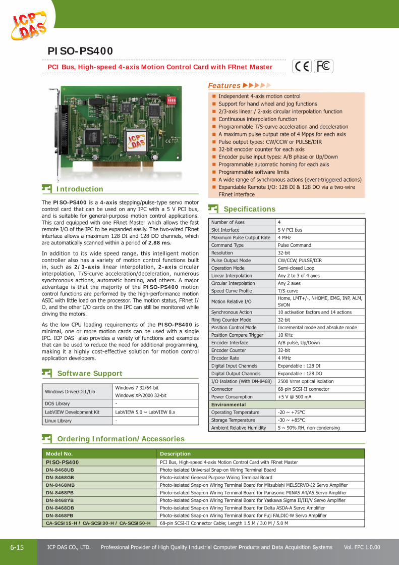
PAC Products
6-15 ICP DAS CO., LTD. Professional Provider of High Quality Industrial Computer Products and Data Acquisition Systems Vol. FPC 1.0.00
Windows Driver/DLL/LibWindows 7 32/64-bit
Windows XP/2000 32-bit
DOS Library -
LabVIEW Development Kit LabVIEW 5.0 ~ LabVIEW 8.x
Linux Library -
Number of Axes 4
Slot Interface 5 V PCI bus
Maximum Pulse Output Rate 4 MHz
Command Type Pulse Command
Resolution 32-bit
Pulse Output Mode CW/CCW, PULSE/DIR
Operation Mode Semi-closed Loop
Linear Interpolation Any 2 to 3 of 4 axes
Circular Interpolation Any 2 axes
Speed Curve Profi le T/S-curve
Motion Relative I/OHome, LMT+/-, NHOME, EMG, INP, ALM, SVON
Synchronous Action 10 activation factors and 14 actions
Ring Counter Mode 32-bit
Position Control Mode Incremental mode and absolute mode
Position Compare Trigger 10 KHz
Encoder Interface A/B pulse, Up/Down
Encoder Counter 32-bit
Encoder Rate 4 MHz
Digital Input Channels Expandable : 128 DI
Digital Output Channels Expandable : 128 DO
I/O Isolation (With DN-8468) 2500 Vrms optical isolation
Connector 68-pin SCSI-II connector
Power Consumption +5 V @ 500 mA
Environmental
Operating Temperature -20 ~ +75°C
Storage Temperature -30 ~ +85°C
Ambient Relative Humidity 5 ~ 90% RH, non-condensing
Ordering Information/Accessories
Model No. Description
PISO-PS400 PCI Bus, High-speed 4-axis Motion Control Card with FRnet Master
DN-8468UB Photo-isolated Universal Snap-on Wiring Terminal Board
DN-8468GB Photo-isolated General Purpose Wiring Terminal Board
DN-8468MB Photo-isolated Snap-on Wiring Terminal Board for Mitsubishi MELSERVO-J2 Servo Amplifi er
DN-8468PB Photo-isolated Snap-on Wiring Terminal Board for Panasonic MINAS A4/A5 Servo Amplifi er
DN-8468YB Photo-isolated Snap-on Wiring Terminal Board for Yaskawa Sigma II/III/V Servo Amplifi er
DN-8468DB Photo-isolated Snap-on Wiring Terminal Board for Delta ASDA-A Servo Amplifi er
DN-8468FB Photo-isolated Snap-on Wiring Terminal Board for Fuji FALDIC-W Servo Amplifi er
CA-SCSI15-H / CA-SCSI30-H / CA-SCSI50-H 68-pin SCSI-II Connector Cable; Length 1.5 M / 3.0 M / 5.0 M
Specifi cations
Software Support
The PISO-PS400 is a 4-axis stepping/pulse-type servo motor control card that can be used on any IPC with a 5 V PCI bus, and is suitable for general-purpose motion control applications. This card equipped with one FRnet Master which allows the fast remote I/O of the IPC to be expanded easily. The two-wired FRnet interface allows a maximum 128 DI and 128 DO channels, which are automatically scanned within a period of 2.88 ms. In addition to its wide speed range, this intelligent motion controller also has a variety of motion control functions built in, such as 2/3-axis linear interpolation, 2-axis circular interpolation, T/S-curve acceleration/deceleration, numerous synchronous actions, automatic homing, and others. A major advantage is that the majority of the PISO-PS400 motion control functions are performed by the high-performance motion ASIC with little load on the processor. The motion status, FRnet I/O, and the other I/O cards on the IPC can still be monitored while driving the motors. As the low CPU loading requirements of the PISO-PS400 is minimal, one or more motion cards can be used with a single IPC. ICP DAS also provides a variety of functions and examples that can be used to reduce the need for additional programming, making it a highly cost-effective solution for motion control application developers.
Introduction
PISO-PS400PCI Bus, High-speed 4-axis Motion Control Card with FRnet Master
Features Independent 4-axis motion controlSupport for hand wheel and jog functions2/3-axis linear / 2-axis circular interpolation functionContinuous interpolation functionProgrammable T/S-curve acceleration and decelerationA maximum pulse output rate of 4 Mpps for each axisPulse output types: CW/CCW or PULSE/DIR32-bit encoder counter for each axisEncoder pulse input types: A/B phase or Up/DownProgrammable automatic homing for each axisProgrammable software limitsA wide range of synchronous actions (event-triggered actions)Expandable Remote I/O: 128 DI & 128 DO via a two-wire FRnet interface

PAC Products
6-16E-mail: [email protected] Vol. FPC 1.0.00
Website: http://www.icpdas.com
PA
C P
rodu
cts
Pan
el P
rodu
cts
Rem
ote
I/O
M
odul
e an
d U
nit
DA
Q C
ard
Indu
stri
al
Com
mun
icat
ion
Wir
eles
s So
luti
onM
otio
n
Au
tom
atio
nA
cces
sori
esEn
ergy
M
anag
emen
tSo
luti
on
Number of Axes 4
Slot Interface Universal PCI Bus
Maximum Pulse Output Rate 4 MHz
Command Type Pulse Command
Pulse Output Mode CW/CCW, PULSE/DIR
Operation Mode Semi-closed Loop
Linear Interpolation Any 2 to 3 of 4 axes
Circular Interpolation Any 2 axes
Speed Curve Profi le T/S curve
Mechanical Switch Input Home, LMT+/-, NHOME, EMG
Servo I/O InterfaceInput : INP, ALM Output: SVON, ALM_RST, ERC
Synchronous Action 10 activation factors and 14 actions
Ring Counter Mode 32-bit
Position Control Mode Incremental mode and absolute mode
Position Compare Trigger 4 MHz
Encoder Interface A/B pulse, Up/Down
Encoder Counter 32-bit
Encoder Counting Rate 4 MHz
Digital Input ChannelsLocal : 4 DIExpandable : 128 DI
Digital Output ChannelsLocal : 4 DOExpandable : 128 DO
I/O Isolation 2500 Vrms optical isolation
Connector 100-pin SCSI-II
Power Consumption +5 V @ 500 mA
Environmental
Operating Temperature -20 ~ +75°C
Storage Temperature -30 ~ +85°C
Ambient Relative Humidity 5 ~ 90% RH, non-condensing
Windows Driver/DLL/LibWindows 7 32/64-bit Windows XP/2000 32-bit
DOS Library -
LabVIEW Development Kit -
Linux Library -
Ordering Information/Accessories
Model No. Description
PISO-PS410 PCI Bus, High-speed 4-axis Motion Control Card with FRnet Master
DN-84100U Universal Snap-on Wiring Terminal Board for PISO-PS410 and PISO-PS810
CA-SCSI100-15 SCSI-II 100-pin & 100-pin Male Connector Cable, Length 1.5 M.
Specifi cations
Software Support
The PISO-PS410 is a 4-axis stepping/pulse-type servo motor control card that can be used on any IPC with a 5 V or 3.3 V PCI bus, and is suitable for general-purpose motion control applications. This card equipped with one FRnet Master which allows the fast remote I/O of the IPC to be expanded easily. The two-wired FRnet interface allows a maximum 128 DI and 128 DO channels, which are automatically scanned within a period of 0.72 ms.
In addition to its wide speed range, this intelligent motion controller also has a variety of motion control functions built in, such as 2/3-axis linear interpolation, 2-axis circular interpolation, T/S-curve acceleration/deceleration, numerous synchronous actions, automatic homing, and others. A major advantage is that the majority of the PISO-PS410 motion control functions are performed by the high-performance motion ASIC with little load on the processor. The motion status, FRnet I/O, and the other I/O cards on the IPC can still be monitored while driving the motors. As the low CPU loading requirements of the PISO-PS410 is minimal, one or more motion cards can be used with a single IPC. ICP DAS also provides a variety of functions and examples that can be used to reduce the need for additional programming, making it a highly cost-effective solution for motion control application developers.
Introduction
PISO-PS410PCI Bus, High-speed 4-axis Motion Control Card with FRnet Master
Features Independent 4-axis motion control
Support for hand wheel and jog functions
4-step home modes with auto-searching
2/3-axis linear interpolation function
2-axis circular interpolation function
Programmable T/S-curve acceleration and deceleration
Programmable ring counter
Alarm reset and error counter clear output (ERC)
High-speed auto incremental and auto reloadable compare output (CMP)
Expandable remote I/O: 128 DI and 128 DO via a two-wire FRnet interface.

PAC Products
6-17 ICP DAS CO., LTD. Professional Provider of High Quality Industrial Computer Products and Data Acquisition Systems Vol. FPC 1.0.00
Number of Axes 6
Slot Interface Universal PCI Bus
Maximum Pulse Output Rate 4 MHz
Command Type Pulse Command
Servo Update Rate 2 KHz
Pulse Output Mode CW/CCW, PULSE/DIR, A/B pulse
Operation Mode Full-closed Loop/Semi-closed Loop
Linear Interpolation Any 2 to 6 of 6 axes
Circular Interpolation Any 2 to 3 of 6 axes
Speed Curve Profi le T/S-curve
Mechanical Switch Input Home, LMT+/-, NHOME, LTC, EMG
Servo I/O InterfaceInput: INP, ALM, RDYOutput: SVON, ALM_RST, ERC
Ring Counter Mode 32-bit
Position Control Mode Incremental mode and absolute mode
Position Compare Trigger 4 MHz
Encoder Interface A/B pulse, Up/Down
Encoder Counter 32-bit
Encoder Counting Rate 12 MHz
Digital Input ChannelsLocal: 12 DIExpandable: 128 DI
Digital Output ChannelsLocal: 3 DOExpandable: 128 DO
I/O Isolation (with DN-8368) 2500 Vrms optical isolation
Connector 68-pin VHDCI Connector and 20-pin SCSI-II
Power Consumption +5 V @ 500 mA
Environmental
Operating Temperature 0 ~ +60°C
Storage Temperature -20 ~ +80°C
Ambient Relative Humidity 5 ~ 90% RH, non-condensing
Ordering Information/Accessories
Model No. Description
PISO-PS600 PCI Bus, High-Speed, DSP-based, 6-axis Motion Control Card with FRnet Master
DN-8368UB Photo-isolated Universal Snap-on wiring terminal board
DN-8368GB Photo-isolated General-purpose wiring terminal board
DN-8368MB Photo-isolated Snap-on wiring terminal board for Mitsubishi MELSERVO-J2 servo amplifi er
DN-20M Manual-Pulse-Generator (MPG) and FRnet Input Board for PISO-PS600/VS600/PMDK (RoHS)
CA-MINI68-15 68-pin VHDCI to SCSI-II Connector Cable, Length 1.5 M
CA-SCSI20-M1 /CA-SCSI20-M3 /CA-SCSI20-M5 20-pin SCSI-II Male connector cable (for Mitsubishi J2 series motor), Length 1 M / 3 M / 5 M.
Specifi cations
Windows Driver/DLL/LibWindows 7 32/64-bit
Windows XP/2000 32-bit
DOS Library -
LabVIEW Development Kit -
Linux Library -
Software Support
The PISO-PS600 controller combines a new generation 1600 MIPS digital signal processor with a 9526 logic element FPGA (Field Programmable Gate Array), I/O buffering circuitry, and motion control characterization software to control the position of 6-axis pulse command servo/stepper motors. The PISO-PS600 not only realizes motion control using full-closed loop (or semi-closed loop) operations and error handling, but also adopts feed-forward gain to reduce the speed profile following errors to achieve position control.
The PISO-PS600 can be used on any IPC with a PCI bus, and is suitable for general-purpose motion control applications. This card also contains one FRnet port which allows the fast digital I/O of the IPC to be easily expanded. This two-wired FRnet interface allows a maximum 128 DI and 128 DO channels, which are automatically scanned within a period of 0.72 ms. In additions to its wide speed range, this intelligent motion controller also has a variety of built-in motion control functions, such as 2- to 6-axis linear interpolation, 2- to 3-axis circular interpolation, T/S-curve acceleration/deceleration, and automatic homing, etc.
Introduction
PISO-PS600PCI Bus, High-speed, DSP-based, 6-axis Motion Control Card with FRnet Master
Features DSP-based motion control card with PCI interfaceIndependent 6-axis motion controlSupport both full-closed and semi-closed control modesMaximum pulse output frequency: 4 MppsMaximum Encoder input frequency: 12 MHz4-step home mode with auto-searching2- to 6-axis linear/2- to 3-axis circular interpolation functionProgrammable T/S-curve acceleration and decelerationChange speed and position on the fl yHigh-speed position latch and compare triggerFully-functional manual-pulse-generator and jog functionsExpandable remote I/O: 128 DI and 128 DO via a two-wire FRnet interface.

PAC Products
6-18E-mail: [email protected] Vol. FPC 1.0.00
Website: http://www.icpdas.com
PA
C P
rodu
cts
Pan
el P
rodu
cts
Rem
ote
I/O
M
odul
e an
d U
nit
DA
Q C
ard
Indu
stri
al
Com
mun
icat
ion
Wir
eles
s So
luti
onM
otio
n
Au
tom
atio
nA
cces
sori
esEn
ergy
M
anag
emen
tSo
luti
on
Number of Axes 8
Slot Interface Universal PCI bus
Maximum Pulse Output Rate 4 MHz
Command Type Pulse Command
Resolution 32-bit
Pulse Output Mode CW/CCW, PULSE/DIR
Operation Mode Semi-closed Loop
Linear Interpolation 2 groups of 2 to 3 axes Interpolation
Circular Interpolation 2 groups of 2 axes Interpolation
Speed Curve Profi le T/S curve
Motion Relative I/OHome, LMT+/-, NHOME, EMG, INP, ALM, SVON, ALM_RST, ERC
Synchronous Action 10 activation factors and 14 actions
Ring Counter Mode 32-bit
Position Control Mode Incremental mode and absolute mode
Position Compare Trigger 4 MHz
Encoder Interface A/B Pulse, Up/Down
Encoder Counter 32-bit
Encoder Rate 4 MHz
Digital Input ChannelsLocal : 8 DIExpandable : 128 DI
Digital Output ChannelsLocal : 8 DOExpandable : 128 DO
I/O Isolation 2500 Vrms optical isolation
Connector 100-pin VHDCI
Power Consumption +5 V @ 500 mA
Environmental
Operating Temperature -20 ~ +75°C
Storage Temperature -30 ~ +85°C
Ambient Relative Humidity 5 ~ 90% RH, non-condensing
Ordering Information/Accessories
Model No. Description
PISO-PS810 PCI Bus, High-speed 8-axis Motion Control Card with FRnet Master
DN-84100U Universal Snap-on Wiring Terminal Board for PISO-PS410 and PISO-PS810
CA-MINI100-15 100-pin VHDCI to SCSI-II Connector Cable, Length 1.5 M
Specifi cations
Windows Driver/DLL/LibWindows 7 32/64-bit
Windows XP/2000 32-bit
DOS Library -
LabVIEW Development Kit -
Linux Library -
Software Support
The PISO-PS810 is a 8-axis stepping/pulse-type servo motor control card that can be used on any IPC with a 5 V or 3.3 V PCI bus, and is suitable for general-purpose motion applications. This card equipped with one FRnet Master which allows the fast remote I/O of the IPC to be expanded easily. The two-wired FRnet interface allows a maximum 128 DI and 128 DO channels, which are automatically scanned within a period of 0.72 ms.
In addition to its wide speed range, this intelligent motion controller also has a variety of motion control functions built in, such as 2/3-axis linear interpolation, 2-axis circular interpolation, T/S-curve acceleration/deceleration, numerous synchronous actions, automatic homing, and others. A major advantage is that the majority of the PISO-PS810 motion control functions are performed by the high-performance motion ASIC with little load on the processor. The motion status, FRnet I/O, and the other I/O cards on the IPC can still be monitored while driving the motors.
As the low CPU loading requirements of the PISO-PS810 is minimal, one or more motion cards can be used with a single IPC. ICP DAS also provides a variety of functions and examples that can be used to reduce the need for additional programming, making it a highly cost-effective solution for motion control application developers.
Introduction
Features Independent 8-axis motion control
Support for hand wheel and jog functions
4-step home modes with auto-searching
2/3-axis linear interpolation function
2-axis circular interpolation function
Programmable T/S-curve acceleration and deceleration
Programmable ring counter
Alarm reset and error counter clear output (ERC)High-speed auto-incremental and auto-reloadable compare output (CMP)Expandable remote I/O: 128 DI & 128 DO via a two-wire FRnet interface
Available soonAvailable soonPISO-PS810PCI Bus, High-speed 8-axis Motion Control Card with FRnet Master

PAC Products
6-19 ICP DAS CO., LTD. Professional Provider of High Quality Industrial Computer Products and Data Acquisition Systems Vol. FPC 1.0.00
Number of Axes 6
Slot Interface Universal PCI bus
Maximum Pulse Output Rate 4 MHz
Command Type Pulse command, V command
Resolution 32-bit
Servo Update Rate User Programmable
Pulse Output Mode CW/CCW, PULSE/DIR
Motion Relative I/OHome, LMT+/-, NHOME, EMG, INP, ALM, SVON, ALM_RST, ERC
Position Compare Trigger User Programmable
Encoder Interface A/B pulse, Up/Down
Encoder Counter 32-bit
Encoder Counting Rate 12 MHz
Digital Input Channels Expandable: 128 DI
Digital Output Channels Expandable: 128 DO
I/O Isolation (with DN-8368) 2500 Vrms optical isolation
Connector 68-pin SCSI-II connector & 20-pin SCSI-II
Power Consumption -
Environmental
Operating Temperature -20 ~ +75°C
Storage Temperature -30 ~ +85°C
Ambient Relative Humidity 5 ~ 90% RH, non-condensing
Specifi cations
Ordering Information/Accessories
Model No. Description
PMDK PCI Bus DSP-based Professional Motion Development Kit
DN-8368UB Photo-isolated Universal Snap-on wiring terminal board
DN-8368GB Photo-isolated General-purpose wiring terminal board
DN-8368MB Photo-isolated Snap-on wiring terminal board for Mitsubishi MELSERVO-J2 servo amplifi er
DN-20M Manual-Pulse-Generator (MPG) and FRnet Input Board for PISO-PS600/VS600/PMDK (RoHS)
CA-MINI68-15 68-pin VHDCI to SCSI-II Connector Cable, Length 1.5 M
CA-SCSI20-M1 / M3 / M5 SCSI-II 20-pin and 20-pin Male Connector Cable for Mitsubishi Motor, Length 1 M / 3 M / 5 M.
CA-2P4C-0100 The Cable for FRnet Modules, Length 100 M.
The PMDK is a DSP-based PCI motion control card suitable for the development of professional motion control applications, and can be used with any IPC that has a 5 V PCI bus. A wide range of applications can be implemented thanks to the integration of a high-speed DSP (TI C672x), an FPGA (Field Programmable Gate Array), and I/O buffering circuitry. A diverse array of I/O interfaces are incorporated into the PMDK, including 6 channels for pulse I/O, 6 channels for AI/AO and a variety of DI/DO channels. The card also includes a single two-wire FRnet port that can be used to remotely control up to 128 DI and 128 DO channels, which, together with the numerous software samples that are provided, allows the rapid development of custom programs.
The PMDK enables users to implement a variety of cost-effective motion control functions, including multi-axis linear and circular interpolation with acceleration/deceleration processing. A variety of synchronous actions are also possible through programming. The included sample software can be used to design custom motion functions which can then be appended to the original motion command set. DSP programs are developed based on a real-time kernel (DSP/BIOS), meaning that motion status, FRnet I/O status and the status of other I/O interfaces can still be monitored while driving operations are being performed, and, as the loading on the CPU is very low, one or more motion cards can be used on a single IPC.
If the PMDK is to be used for signal processing, users can refer to a range of samples provided by ICP DAS illustrating how to implement FFT, FIR and IIR, together with the resources provided by TI. In the future, ICP DAS will be providing a wider library of functions and examples that will further reduce the level of programming required by users in order to implement their custom applications. In summary, the PMDK is a highly cost-effective solution for users intending to develop custom applications for motion control, process control, I/O logic control, digital processing, and applications in a wide range of other domains.
Introduction
Features DSP-based control card with PCI interface
Capable of 6-axis motion control
Maximum Pulse Output Frequency: 4 Mpps
Maximum Encoder Input Frequency: 12 Mpps
High-speed position latching and comparing functions
Home, positive and negative limit sensors for each axis
Manual-pulse-generator (MPG) interface
Expandable Remote I/O: 128 DI & 128 DO via a two-wire FRnet interface
PMDKPCI Bus, DSP-based Professional Motion Development Kit
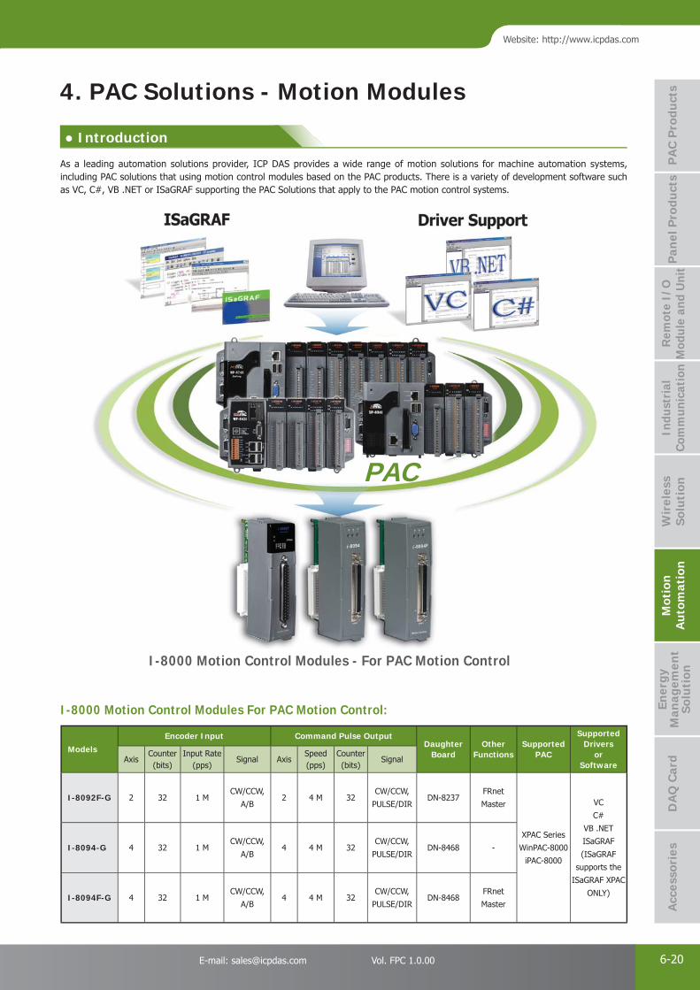
PAC Products
6-20E-mail: [email protected] Vol. FPC 1.0.00
Website: http://www.icpdas.com
PA
C P
rodu
cts
Pan
el P
rodu
cts
Rem
ote
I/O
M
odul
e an
d U
nit
DA
Q C
ard
Indu
stri
al
Com
mun
icat
ion
Wir
eles
s So
luti
onM
otio
n
Au
tom
atio
nA
cces
sori
esEn
ergy
M
anag
emen
tSo
luti
on
Models
Encoder Input Command Pulse OutputDaughter
BoardOther
FunctionsSupported
PAC
SupportedDrivers
or Software
AxisCounter(bits)
Input Rate(pps)
Signal AxisSpeed(pps)
Counter(bits)
Signal
I-8092F-G 2 32 1 MCW/CCW,
A/B2 4 M 32
CW/CCW,
PULSE/DIRDN-8237
FRnet
Master
XPAC Series
WinPAC-8000
iPAC-8000
VC
C#
VB .NET
ISaGRAF
(ISaGRAF
supports the
ISaGRAF XPAC
ONLY)
I-8094-G 4 32 1 MCW/CCW,
A/B4 4 M 32
CW/CCW,
PULSE/DIRDN-8468 -
I-8094F-G 4 32 1 MCW/CCW,
A/B4 4 M 32
CW/CCW,
PULSE/DIRDN-8468
FRnet
Master
I-8000 Motion Control Modules For PAC Motion Control:
PAC
I-8000 Motion Control Modules - For PAC Motion Control
4. PAC Solutions - Motion Modules
As a leading automation solutions provider, ICP DAS provides a wide range of motion solutions for machine automation systems, including PAC solutions that using motion control modules based on the PAC products. There is a variety of development software such as VC, C#, VB .NET or ISaGRAF supporting the PAC Solutions that apply to the PAC motion control systems.
● Introduction
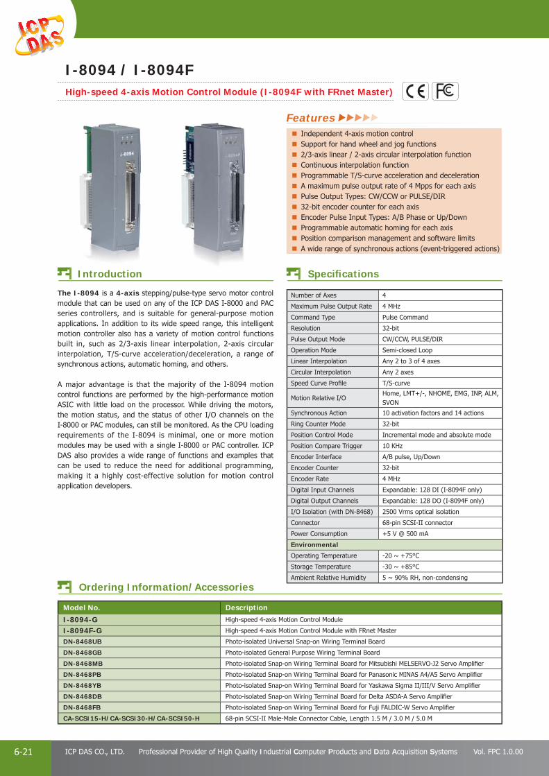
PAC Products
6-21 ICP DAS CO., LTD. Professional Provider of High Quality Industrial Computer Products and Data Acquisition Systems Vol. FPC 1.0.00
Number of Axes 4
Maximum Pulse Output Rate 4 MHz
Command Type Pulse Command
Resolution 32-bit
Pulse Output Mode CW/CCW, PULSE/DIR
Operation Mode Semi-closed Loop
Linear Interpolation Any 2 to 3 of 4 axes
Circular Interpolation Any 2 axes
Speed Curve Profi le T/S-curve
Motion Relative I/OHome, LMT+/-, NHOME, EMG, INP, ALM, SVON
Synchronous Action 10 activation factors and 14 actions
Ring Counter Mode 32-bit
Position Control Mode Incremental mode and absolute mode
Position Compare Trigger 10 KHz
Encoder Interface A/B pulse, Up/Down
Encoder Counter 32-bit
Encoder Rate 4 MHz
Digital Input Channels Expandable: 128 DI (I-8094F only)
Digital Output Channels Expandable: 128 DO (I-8094F only)
I/O Isolation (with DN-8468) 2500 Vrms optical isolation
Connector 68-pin SCSI-II connector
Power Consumption +5 V @ 500 mA
Environmental
Operating Temperature -20 ~ +75°C
Storage Temperature -30 ~ +85°C
Ambient Relative Humidity 5 ~ 90% RH, non-condensing
Ordering Information/Accessories
Model No. Description
I-8094-G High-speed 4-axis Motion Control Module
I-8094F-G High-speed 4-axis Motion Control Module with FRnet Master
DN-8468UB Photo-isolated Universal Snap-on Wiring Terminal Board
DN-8468GB Photo-isolated General Purpose Wiring Terminal Board
DN-8468MB Photo-isolated Snap-on Wiring Terminal Board for Mitsubishi MELSERVO-J2 Servo Amplifi er
DN-8468PB Photo-isolated Snap-on Wiring Terminal Board for Panasonic MINAS A4/A5 Servo Amplifi er
DN-8468YB Photo-isolated Snap-on Wiring Terminal Board for Yaskawa Sigma II/III/V Servo Amplifi er
DN-8468DB Photo-isolated Snap-on Wiring Terminal Board for Delta ASDA-A Servo Amplifi er
DN-8468FB Photo-isolated Snap-on Wiring Terminal Board for Fuji FALDIC-W Servo Amplifi er
CA-SCSI15-H/CA-SCSI30-H/CA-SCSI50-H 68-pin SCSI-II Male-Male Connector Cable, Length 1.5 M / 3.0 M / 5.0 M
Specifi cations
The I-8094 is a 4-axis stepping/pulse-type servo motor control module that can be used on any of the ICP DAS I-8000 and PAC series controllers, and is suitable for general-purpose motion applications. In addition to its wide speed range, this intelligent motion controller also has a variety of motion control functions built in, such as 2/3-axis linear interpolation, 2-axis circular interpolation, T/S-curve acceleration/deceleration, a range of synchronous actions, automatic homing, and others.
A major advantage is that the majority of the I-8094 motion control functions are performed by the high-performance motion ASIC with little load on the processor. While driving the motors, the motion status, and the status of other I/O channels on the I-8000 or PAC modules, can still be monitored. As the CPU loading requirements of the I-8094 is minimal, one or more motion modules may be used with a single I-8000 or PAC controller. ICP DAS also provides a wide range of functions and examples that can be used to reduce the need for additional programming, making it a highly cost-effective solution for motion control application developers.
Introduction
Features Independent 4-axis motion controlSupport for hand wheel and jog functions2/3-axis linear / 2-axis circular interpolation functionContinuous interpolation functionProgrammable T/S-curve acceleration and decelerationA maximum pulse output rate of 4 Mpps for each axisPulse Output Types: CW/CCW or PULSE/DIR32-bit encoder counter for each axisEncoder Pulse Input Types: A/B Phase or Up/DownProgrammable automatic homing for each axisPosition comparison management and software limitsA wide range of synchronous actions (event-triggered actions)
I-8094 / I-8094FHigh-speed 4-axis Motion Control Module (I-8094F with FRnet Master)
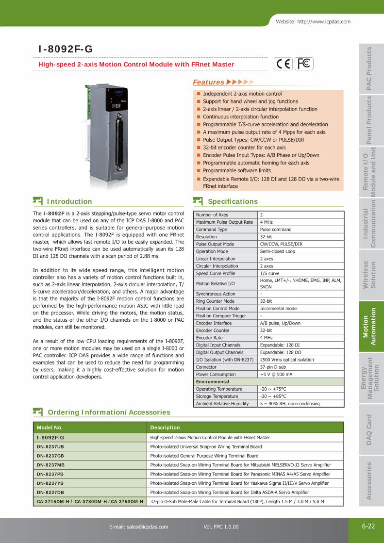
PAC Products
6-22E-mail: [email protected] Vol. FPC 1.0.00
Website: http://www.icpdas.com
PA
C P
rodu
cts
Pan
el P
rodu
cts
Rem
ote
I/O
M
odul
e an
d U
nit
DA
Q C
ard
Indu
stri
al
Com
mun
icat
ion
Wir
eles
s So
luti
onM
otio
n
Au
tom
atio
nA
cces
sori
esEn
ergy
M
anag
emen
tSo
luti
on
Number of Axes 2
Maximum Pulse Output Rate 4 MHz
Command Type Pulse command
Resolution 32-bit
Pulse Output Mode CW/CCW, PULSE/DIR
Operation Mode Semi-closed Loop
Linear Interpolation 2 axes
Circular Interpolation 2 axes
Speed Curve Profi le T/S curve
Motion Relative I/OHome, LMT+/-, NHOME, EMG, INP, ALM, SVON
Synchronous Action -
Ring Counter Mode 32-bit
Position Control Mode Incremental mode
Position Compare Trigger -
Encoder Interface A/B pulse, Up/Down
Encoder Counter 32-bit
Encoder Rate 4 MHz
Digital Input Channels Expandable: 128 DI
Digital Output Channels Expandable: 128 DO
I/O Isolation (with DN-8237) 2500 Vrms optical isolation
Connector 37-pin D-sub
Power Consumption +5 V @ 500 mA
Environmental
Operating Temperature -20 ~ +75°C
Storage Temperature -30 ~ +85°C
Ambient Relative Humidity 5 ~ 90% RH, non-condensing
Ordering Information/Accessories
Model No. Description
I-8092F-G High-speed 2-axis Motion Control Module with FRnet Master
DN-8237UB Photo-isolated Universal Snap-on Wiring Terminal Board
DN-8237GB Photo-isolated General Purpose Wiring Terminal Board
DN-8237MB Photo-isolated Snap-on Wiring Terminal Board for Mitsubishi MELSERVO-J2 Servo Amplifi er
DN-8237PB Photo-isolated Snap-on Wiring Terminal Board for Panasonic MINAS A4/A5 Servo Amplifi er
DN-8237YB Photo-isolated Snap-on Wiring Terminal Board for Yaskawa Sigma II/III/V Servo Amplifi er
DN-8237DB Photo-isolated Snap-on Wiring Terminal Board for Delta ASDA-A Servo Amplifi er
CA-3715DM-H / CA-3730DM-H /CA-3750DM-H 37-pin D-Sub Male-Male Cable for Terminal Board (180º), Length 1.5 M / 3.0 M / 5.0 M
Specifi cations
The I-8092F is a 2-axis stepping/pulse-type servo motor control module that can be used on any of the ICP DAS I-8000 and PAC series controllers, and is suitable for general-purpose motion control applications. The I-8092F is equipped with one FRnet master, which allows fast remote I/O to be easily expanded. The two-wire FRnet interface can be used automatically scan its 128 DI and 128 DO channels with a scan period of 2.88 ms.
In addition to its wide speed range, this intelligent motion controller also has a variety of motion control functions built in, such as 2-axis linear interpolation, 2-axis circular interpolation, T/S-curve acceleration/deceleration, and others. A major advantage is that the majority of the I-8092F motion control functions are performed by the high-performance motion ASIC with little load on the processor. While driving the motors, the motion status, and the status of the other I/O channels on the I-8000 or PAC modules, can still be monitored.
As a result of the low CPU loading requirements of the I-8092F, one or more motion modules may be used on a single I-8000 or PAC controller. ICP DAS provides a wide range of functions and examples that can be used to reduce the need for programming by users, making it a highly cost-effective solution for motion control application developers.
Introduction
Features Independent 2-axis motion controlSupport for hand wheel and jog functions2-axis linear / 2-axis circular interpolation functionContinuous interpolation functionProgrammable T/S-curve acceleration and decelerationA maximum pulse output rate of 4 Mpps for each axisPulse Output Types: CW/CCW or PULSE/DIR32-bit encoder counter for each axisEncoder Pulse Input Types: A/B Phase or Up/DownProgrammable automatic homing for each axisProgrammable software limits
Expandable Remote I/O: 128 DI and 128 DO via a two-wire FRnet interface
I-8092F-GHigh-speed 2-axis Motion Control Module with FRnet Master

PAC Products
6-23 ICP DAS CO., LTD. Professional Provider of High Quality Industrial Computer Products and Data Acquisition Systems Vol. FPC 1.0.00
2. Circular Interpolation 3. Continuous Interpolation
5. High Speed Position Compare 6. Huge Command Buffer and Real Time Coordinate Transformation Suitable for Robotic Control
4. Four Steps Automatic Home Searching
1. Linear Interpolation
Motion Products Features of Motion Functions
Model 1. Linear Interpolation
2. Circular Interpolation
3. Continuous Interpolation
4. Four Steps Automatic Home
Searching
5. High Speed Position Compare
6. Huge Command Buffer and Real Time Coordinate Transformation
Suitable for Robotic Control
PC-based Motion Control Cards
PISO-PS200 2-axis
2-axisConstant Vector
Speed
Yes
-
-PISO-PS4003-axis
YesPISO-PS410
PISO-PS600 6-axis 3-axis With Acc. and Dec. Yes
PISO-PS8102 Groups
3-axis2 Groups
2-axisConstant Vector
Speed-
Motion Control Modules for PAC
I-8092F 2-axis
2-axisConstant Vector
SpeedYes
-
-I-80943-axis Yes
I-8094F
5. Features of Motion Function

Energy Management Solution P 7-11
Front-End Power Meter Concentrator P 7-53
Applications P 7-185
● 3.1 Smart Power Meter Concentrator - - - - - - - - - - - - - - - - - - - - - - - - - P 7-7
● 4.1 Smart Power Meter (PM-3133/-MTCP/-CPS) - - - - - - - - - - - - - - - - - - P 7-10 (PM-3112/-MTCP/-CPS & PM-3114/-MTCP/-CPS) - - - - - - - - - - - - - - - P 7-12
(PM-4324) - - - - - - - - - - - - - - - - - - - - - - - - - - - - - - - - - - - - - - - - P 7-14
● 4.2 True RMS Input Module (M-7017RMS) - - - - - - - - - - - - - - - - - - - - - - P 7-16
● 2.1 InduSoft SCADA Software - - - - - - - - - - - - - - - - - - - - - - - - - - - - - - P 7-3
Back-End Management Software P 7-2
Front-End Devices P 7-9
2
4
Energy Management Energy Management SolutionSolution
Energy Management Solution 7

PAC Products
7-1 ICP DAS CO., LTD. Professional Provider of High Quality Industrial Computer Products and Data Acquisition Systems Vol. FPC 1.0.00
● Introduction
1. Energy Management Solution
In order to achieve more effi cient use of energy and reduce resources consumption, ICP DAS provides an innovative total solution in energy saving by connecting PMC (Power Meter Concentrator) to the Power Meters via RS-485 or Ethernet interface, it can measure and monitor the power consumption of the devices, machines, lighting, air conditioning or other electricity equipments. In addition, PMC also provides power demand management and alarm notifi cation functions. With the integration of ICP DAS I/O modules and the standard Modbus I/O devices, it can perform logic control or load shedding of the devices based on the power demand in real time. PMC also supports Modbus TCP/RTU protocol for seamless integration with SCADA. So that the administrator can monitor the status of power consumption of each device and perform statistics and analysis of the power information, thus improving the overall effi ciency in electricity consumption to save costs on utility bills.
This innovative total solution for energy saving includes: front-end Smart Power Meter, Power Meter Concentrator, back-end software tool for database import operation (PMC Data Server) and InduSoft SCADA software. In addition to hardware devices, ICP DAS also provides total solution so that the user could easily view power data by their mobile phones or PC, the administrator could set up the system quickly and the data can be recorded in real time for energy consumption inquiry to achieve effective energy saving. During the early stage, if the scale of the application is small, the user could simply use Smart Power Meter and PMC to set up a simple power monitoring system, once the scale of the application is expanded, the user could get the back-end software tool involved and build an easy-to-expand power monitoring system via blocks stacked structure. By this way, the system will be highly fl exible and could be implemented in phases to meet various requirements.
System Architecture
Features Rapidly construct energy management systems without extra software tools.Built-in IF-THEN-ELSE logic Engine, Include: Timer, Schedule, SSL Email sending, power demand, alarm notifi cation...etc.Display real-time or historical power data trends and statistics reports.Support Modbus TCP/RTU, SNMP V2c, SNMP Trap, and MQTT protocol.Support DDNS and VPN communication mechanism.Support data logger operation, FTP Server/Client and data recovery mechanism.Support ICP DAS Smart Power Meters (RS-485 & Ethernet) and remote I/O modules.
Power Management Logic Control Data Redundancy D

PAC Products
7-2E-mail: [email protected] Vol. FPC 1.0.00
Website: http://www.icpdas.com
PA
C P
rodu
cts
Pan
el P
rodu
cts
Rem
ote
I/O
M
odul
e an
d U
nit
DA
Q C
ard
Indu
stri
al
Com
mun
icat
ion
Wir
eles
s So
luti
onM
otio
n
Au
tom
atio
nEn
ergy
M
anag
emen
tSo
luti
onA
cces
sori
es
2. Back-End Management SoftwareInduSoft Web StudioInduSoft Web Studio is a powerful, integrated collection of automation tool that includes all the building blocks needed to develop modern Human Machine Interface (HMI), Supervisory Control and Data Acquisition (SCADA) systems, and embedded instrumentation and control applications. InduSoft Web Studio supports all Windows runtime platforms, ranging from Windows CE, Windows XP, Windows XP Embedded, Vista, Windows 7 (including 32 and 64 bit), and Windows Server Editions, along with built-in support for local or remote (web) based visualization. InduSoft also conforms to industry standards such as Microsoft .NET, OPC, DDE, ODBC, XML, and ActiveX. To implement energy saving solution, ICP DAS provides an example project that is based on InduSoft and is connected to PMC concentrators for power data acquisition. This example project features the following functions and can be a good reference for users to build their specifi c Energy saving solutions.
• Connect to PMC concentrators to receive the historical Power Data log files sent by PMC concentrators, and import them into the InduSoft Database for historical power data display, analysis and management.
• Connect to PMC concentrators by Modbus TCP protocol for the real time Power Data acquisition, and import the data into the InduSoft for real time power data display, analysis and management.
• Provide Web page for displaying real time power data and historical power data.
• Provide data query operation for power data report generation.
Featuring well thought-out SCADA functions and intuitive system development interface, InduSoft is a cost-effective software solution that is perfect for Energy Saving applications and will signifi cantly reduce the time and labor spent in the process of system developments.
EZ Data Logger
EZ Data Logger is the software that ICP DAS provides for users to easily build a SCADA system on Windows 2000/XP/Vista. It comes with two versions, "Basic" & "Professional". The Basic version is not only full-functioned but free to all ICP DAS users!EZ Data Logger is a small data logger software. It can be applied to small remote I/O system. With its user-friendly interface, users can quickly and easily build a data logger software without any programming skill.
Support DCON, Modbus RTU, Modbus ASCII, Modbus TCP protocols
Support multiple COM Ports and TCP/IP connections
Support Virtual Channel defi nition
Support Control Logic (VB Script)
Support Alarm Notifi er (by sending SMS to cell phone or E-Mail)
Flexible module confi guration (different description and color)
Flexible workgroup confi guration
Real time data trend (with zoom in and zoom out)
Each trend line can store more than 86400 records.
Provide Layout view
Provide IP Camera Viewer
Support local MS Access database (can be exported to excel fi le or csv fi le)
Support MS SQL, MySQL database
Provide Reporter to print trend line or data
Provide High/Low alarm with audio warning
Can search for DCON (I-7000/8000/87K) serial modules
Can search for Modbus (M-7000) serial modules
Provide Value scaling
All operations are done by click mouse and enter value.
Features
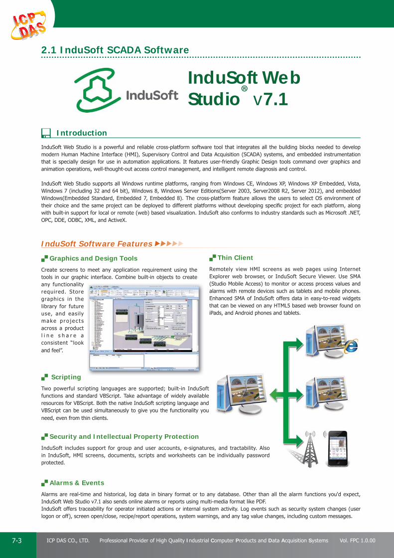
PAC Products
7-3 ICP DAS CO., LTD. Professional Provider of High Quality Industrial Computer Products and Data Acquisition Systems Vol. FPC 1.0.00
InduSoft Web Studio is a powerful and reliable cross-platform software tool that integrates all the building blocks needed to develop modern Human Machine Interface (HMI), Supervisory Control and Data Acquisition (SCADA) systems, and embedded instrumentation that is specially design for use in automation applications. It features user-friendly Graphic Design tools command over graphics and animation operations, well-thought-out access control management, and intelligent remote diagnosis and control.
InduSoft Web Studio supports all Windows runtime platforms, ranging from Windows CE, Windows XP, Windows XP Embedded, Vista, Windows 7 (including 32 and 64 bit), Windows 8, Windows Server Editions(Server 2003, Server2008 R2, Server 2012), and embedded Windows(Embedded Standard, Embedded 7, Embedded 8). The cross-platform feature allows the users to select OS environment of their choice and the same project can be deployed to different platforms without developing specifi c project for each platform, along with built-in support for local or remote (web) based visualization. InduSoft also conforms to industry standards such as Microsoft .NET, OPC, DDE, ODBC, XML, and ActiveX.
InduSoft Web Studio® v7.1
Graphics and Design Tools
Create screens to meet any application requirement using the tools in our graphic interface. Combine built-in objects to create any functionality required. Store graphics in the library for future use, and easi ly make p ro j e c t s across a product l i n e s h a r e a consistent “look and feel”.
Thin Client
Remotely view HMI screens as web pages using Internet Explorer web browser, or InduSoft Secure Viewer. Use SMA (Studio Mobile Access) to monitor or access process values and alarms with remote devices such as tablets and mobile phones. Enhanced SMA of InduSoft offers data in easy-to-read widgets that can be viewed on any HTML5 based web browser found on iPads, and Android phones and tablets.
Scripting
Two powerful scripting languages are supported; built-in InduSoft functions and standard VBScript. Take advantage of widely available resources for VBScript. Both the native InduSoft scripting language and VBScript can be used simultaneously to give you the functionality you need, even from thin clients.
Security and Intellectual Property Protection
InduSoft includes support for group and user accounts, e-signatures, and tractability. Also in InduSoft, HMI screens, documents, scripts and worksheets can be individually password protected.
Alarms & Events
Alarms are real-time and historical, log data in binary format or to any database. Other than all the alarm functions you'd expect, InduSoft Web Studio v7.1 also sends online alarms or reports using multi-media format like PDF. InduSoft offers traceability for operator initiated actions or internal system activity. Log events such as security system changes (user logon or off), screen open/close, recipe/report operations, system warnings, and any tag value changes, including custom messages.
, and tractability. Also individually password
2.1 InduSoft SCADA Software
InduSoft Software Features
Introduction
PAC Products
7-4E-mail: [email protected] Vol. FPC 1.0.00
Website: http://www.icpdas.com
PA
C P
rodu
cts
Pan
el P
rodu
cts
Rem
ote
I/O
M
odul
e an
d U
nit
DA
Q C
ard
Indu
stri
al
Com
mun
icat
ion
Wir
eles
s So
luti
onM
otio
n
Au
tom
atio
nEn
ergy
M
anag
emen
tSo
luti
onA
cces
sori
es
Create once, runs on various platformsBy using InduSoft Web Studio, the user only need to create the project once at PC side, and then the project can be downloaded and run on various configurations of platforms, ranging from the Windows XP/7/8 to the simple handheld PDAs and “smart phones” that use Windows CE/Windows Mobile technology. It also runs on diskless embedded processors and Panel PCs. The cross-platform feature allows the users to select OS environment of their choice and the same project can be deployed to different platforms without developing specifi c project for each platform.
Trends
Real-time and Historical trends are supported. It can log data in binary format or to any local or remote SQL database. Color or fi ll trends with graphic elements to enhance clarity of data. Date/Time based or numeric (X/Y plot) trends give you the fl exibility to display information that best suits your application. InduSoft Web Studio supports vertical and horizontal trending.
Redundancy
InduSoft Web Studio publishes HMI screens as web pages either to Internet Explorer or Secure Viewer. The HMI screen graphics are published as html pages via a "web server". The data is published via a "data server”. InduSoft features:
• Support for redundant web servers
• Support for redundant data servers
InduSoft also allows connections to databases. Databases can be used to log data from Alarms, Events or Trends. The "Grid" object can interact with database directly for “Redundant” operation and “Store and Forward” operation.
Recipes and Reports InduSoft provides fl exible recipe management tools to save time and maintain consistency by automating part parameters or production quantities. The report tools allows user to create clear, concise reports in plain text, RTF, XML, PDF, HTML, and CSV or integrate with Microsoft Offi ce programs such as Excel. Get the data you need, in the format you require to make decisions fast.
Drivers and OPC
IWS 7.1 not only provides over 240 native communication drivers but also native OPC interfaces, such as OPC DA (Server/Client), OPC HDA(Server), UA (Client) and OPC .NET 3.0 (Client). InduSoft Web Studio v7.1 also supports OPC XML as an additional add-on.
Database
Connect to any SQL database (MS SQL, MySQL, Sybase, Oracle), or MS Access or Excel, and ERP/MES systems (including SAP), even from Windows Embedded CE. InduSoft Web Studio is fl exible, offering a built-in interface that doesn’t require knowledge of SQL.
d d i h f i k
IWS Development Package for WindowsInduSoft development package can generate applications for Windows, Windows Embedded and Windows Embedded CE
IWS Runtime Package for Windows InduSoft runtime package for Windows, Windows Embedded
IWS Runtime Package for Windows Embedded CE InduSoft runtime package for Windows Embedded CE
Additional Package for Development or Runtime License
The additional package are number of Web Thin Clients, number of Secure Viewer Thin Clients, number of SMA Thin Clients, number of Communication Drivers, and Communication Add-Ons
p jbe downloaded and run on g
d s
InduSoft Ordering Information
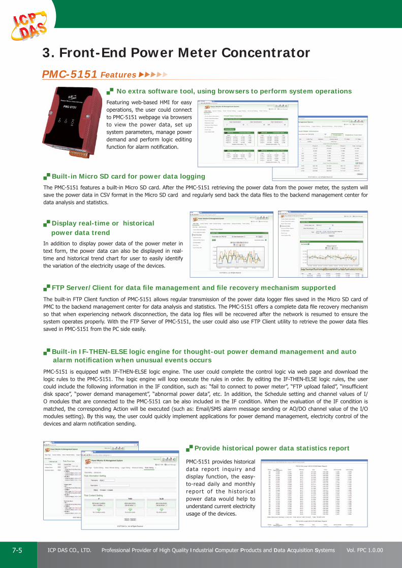
PAC Products
7-5 ICP DAS CO., LTD. Professional Provider of High Quality Industrial Computer Products and Data Acquisition Systems Vol. FPC 1.0.00
Provide historical power data statistics report
PMC-5151 provides historical data report inquiry and display function, the easy-to-read daily and monthly report o f the h is tor ica l power data would help to understand current electricity usage of the devices.
No extra software tool, using browsers to perform system operations
Featuring web-based HMI for easy operations, the user could connect to PMC-5151 webpage via browsers to view the power data, set up system parameters, manage power demand and perform logic editing function for alarm notifi cation.
Display real-time or historical power data trendIn addition to display power data of the power meter in text form, the power data can also be displayed in real-time and historical trend chart for user to easily identify the variation of the electricity usage of the devices.
Built-in Micro SD card for power data logging
The PMC-5151 features a built-in Micro SD card. After the PMC-5151 retrieving the power data from the power meter, the system will save the power data in CSV format in the Micro SD card and regularly send back the data fi les to the backend management center for data analysis and statistics.
FTP Server/Client for data fi le management and fi le recovery mechanism supported
The built-in FTP Client function of PMC-5151 allows regular transmission of the power data logger fi les saved in the Micro SD card of PMC to the backend management center for data analysis and statistics. The PMC-5151 offers a complete data fi le recovery mechanism so that when experiencing network disconnection, the data log fi les will be recovered after the network is resumed to ensure the system operates properly. With the FTP Server of PMC-5151, the user could also use FTP Client utility to retrieve the power data fi les saved in PMC-5151 from the PC side easily.
Built-in IF-THEN-ELSE logic engine for thought-out power demand management and auto alarm notifi cation when unusual events occurs
PMC-5151 is equipped with IF-THEN-ELSE logic engine. The user could complete the control logic via web page and download the logic rules to the PMC-5151. The logic engine will loop execute the rules in order. By editing the IF-THEN-ELSE logic rules, the user could include the following information in the IF condition, such as: “fail to connect to power meter”, “FTP upload failed”, “insuffi cient disk space”, “power demand management”, “abnormal power data”, etc. In addition, the Schedule setting and channel values of I/O modules that are connected to the PMC-5151 can be also included in the IF condition. When the evaluation of the IF condition is matched, the corresponding Action will be executed (such as: Email/SMS alarm message sending or AO/DO channel value of the I/O modules setting). By this way, the user could quickly implement applications for power demand management, electricity control of the devices and alarm notifi cation sending.
3. Front-End Power Meter ConcentratorPMC-5151 Features

PAC Products
7-6E-mail: [email protected] Vol. FPC 1.0.00
Website: http://www.icpdas.com
PA
C P
rodu
cts
Pan
el P
rodu
cts
Rem
ote
I/O
M
odul
e an
d U
nit
DA
Q C
ard
Indu
stri
al
Com
mun
icat
ion
Wir
eles
s So
luti
onM
otio
n
Au
tom
atio
nEn
ergy
M
anag
emen
tSo
luti
onA
cces
sori
es
Offer Flash HMI Tools for user-defi ned HMI interface design
The PMC-5151 provides Flash HMI editing function. The user could design a specific HMI webpage for power monitoring via browser. PMC's Flash HMI editor incorporates Adobe ® Flash graphics technology. The easy-to-use interface and a variety of HMI components enable user to create more diverse, attractive and intuitive HMI web pages to meet requirements of specifi c power monitoring application.
Provide Timer Function
Timer function provides Timeout/Not Timeout status for condition evaluations. With the timer function, the users are able to edit logic that requires timing approach. In addition, the timer function can be reset/started in real time that increases fl exibility when performing logic control.
Support SNMP Function
In addition to Modbus protocol, PMC-5151 also supports SNMP function that allows seamless integration with IT Management software. The users could integrate PMC-5151 with the existing management system and collect the power data of each device by SNMP function easily.
Provide VPN Connection Function
PMC-5151 provides VPN connection to join virtual private network to enhance the flexibility and security of the system.
Provide Schedule function
PMC-5151 provides Schedule function that allows to edit logic for applications that requires Schedule function. The Calendar interface allows to easily set up the schedule for weekdays or weekends so that the user could schedule the operations for the devices as required for power saving.
Modbus TCP/RTU for seamless integration with SCADAThe PMC-5151 supports Modbus TCP/RTU Slave protocol to connect to SCADA software or HMI devices in control center so that it could perform real-time monitoring and control of the electricity usage for the devices. Therefore, the regulation of the system will be more fl exible.
Support a variety of wide-range I/O modules to achieve power control and load shedding of the devices
According to the requirements of the application and based on the devices connected, the PMC-5151 is able to connect to ICP DAS XW-Board, M-7000 I/O modules, standard Modbus TCP/RTU Slave modules or DO Relay channel of the PM Series power meter for real time I/O control operation of the devices, the abundant selections enable maximum fl exibility for system set up and power saving.
PMC Data Server
The PMC Data Server is a database utility designed for connecting to the PMC concentrators. When PMC Data Server is connected to these PMCs by Ethernet, the PMCs will send the power data logger files to the PMC Data Server at scheduled time, and these power data will be transformed to MS Access/MS SQL/MySQL database format for easy data review or inquiry. During the whole process of system development, no programming is required. It takes only a few settings for users to quickly retrieve and view the power data of the devices based on database system and furthermore, enables further process of the data for statistics and analysis.
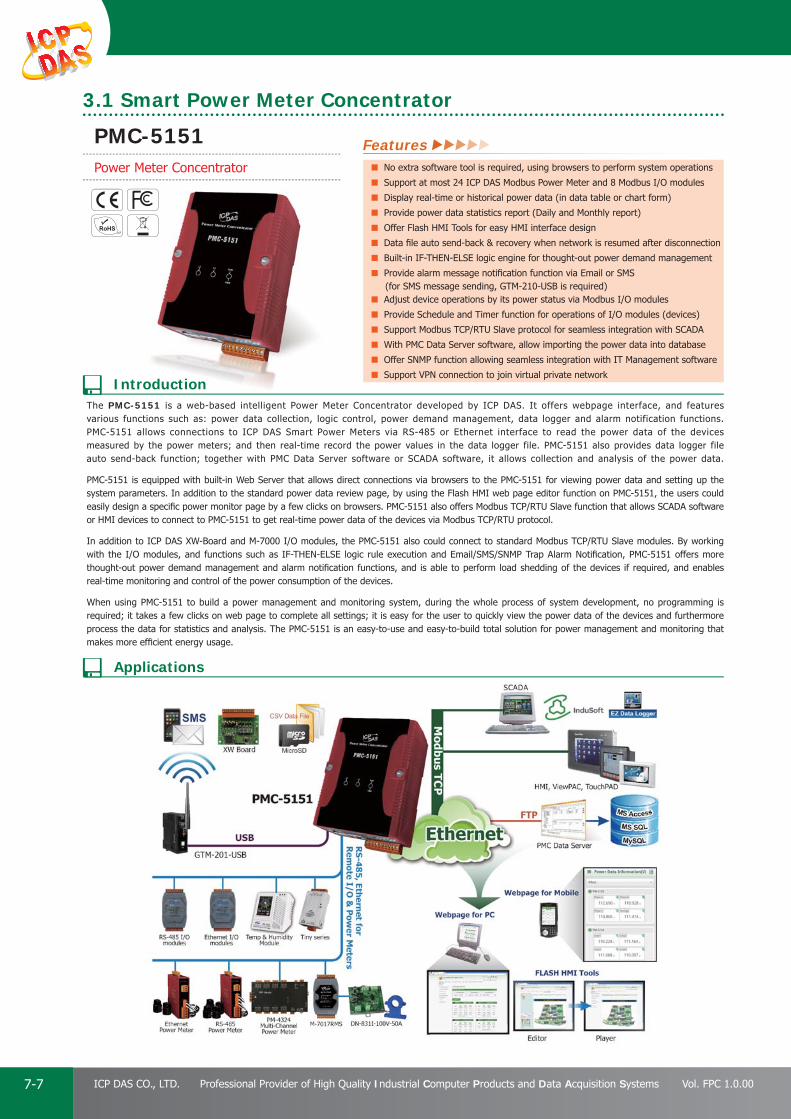
PAC Products
7-7 ICP DAS CO., LTD. Professional Provider of High Quality Industrial Computer Products and Data Acquisition Systems Vol. FPC 1.0.00
The PMC-5151 is a web-based intelligent Power Meter Concentrator developed by ICP DAS. It offers webpage interface, and features various functions such as: power data collection, logic control, power demand management, data logger and alarm notification functions. PMC-5151 allows connections to ICP DAS Smart Power Meters via RS-485 or Ethernet interface to read the power data of the devices measured by the power meters; and then real-time record the power values in the data logger file. PMC-5151 also provides data logger file auto send-back function; together with PMC Data Server software or SCADA software, it allows collection and analysis of the power data. PMC-5151 is equipped with built-in Web Server that allows direct connections via browsers to the PMC-5151 for viewing power data and setting up the system parameters. In addition to the standard power data review page, by using the Flash HMI web page editor function on PMC-5151, the users could easily design a specifi c power monitor page by a few clicks on browsers. PMC-5151 also offers Modbus TCP/RTU Slave function that allows SCADA software or HMI devices to connect to PMC-5151 to get real-time power data of the devices via Modbus TCP/RTU protocol.
In addition to ICP DAS XW-Board and M-7000 I/O modules, the PMC-5151 also could connect to standard Modbus TCP/RTU Slave modules. By working with the I/O modules, and functions such as IF-THEN-ELSE logic rule execution and Email/SMS/SNMP Trap Alarm Notifi cation, PMC-5151 offers more thought-out power demand management and alarm notifi cation functions, and is able to perform load shedding of the devices if required, and enables real-time monitoring and control of the power consumption of the devices.
When using PMC-5151 to build a power management and monitoring system, during the whole process of system development, no programming is required; it takes a few clicks on web page to complete all settings; it is easy for the user to quickly view the power data of the devices and furthermore process the data for statistics and analysis. The PMC-5151 is an easy-to-use and easy-to-build total solution for power management and monitoring that makes more effi cient energy usage.
Features No extra software tool is required, using browsers to perform system operations
Support at most 24 ICP DAS Modbus Power Meter and 8 Modbus I/O modules
Display real-time or historical power data (in data table or chart form)
Provide power data statistics report (Daily and Monthly report)
Offer Flash HMI Tools for easy HMI interface design
Data fi le auto send-back & recovery when network is resumed after disconnection
Built-in IF-THEN-ELSE logic engine for thought-out power demand management
Provide alarm message notifi cation function via Email or SMS (for SMS message sending, GTM-210-USB is required)Adjust device operations by its power status via Modbus I/O modules
Provide Schedule and Timer function for operations of I/O modules (devices)
Support Modbus TCP/RTU Slave protocol for seamless integration with SCADA
With PMC Data Server software, allow importing the power data into database
Offer SNMP function allowing seamless integration with IT Management software
Support VPN connection to join virtual private networkIntroduction
Applications
3.1 Smart Power Meter Concentrator
PMC-5151Power Meter Concentrator

PAC Products
7-8E-mail: [email protected] Vol. FPC 1.0.00
Website: http://www.icpdas.com
PA
C P
rodu
cts
Pan
el P
rodu
cts
Rem
ote
I/O
M
odul
e an
d U
nit
DA
Q C
ard
Indu
stri
al
Com
mun
icat
ion
Wir
eles
s So
luti
onM
otio
n
Au
tom
atio
nEn
ergy
M
anag
emen
tSo
luti
onA
cces
sori
es
Model PMC-5151
System Software
OS Windows CE OS
Embedded Service PMC Runtime, Web server, FTP server
CPU Module
CPU 32-bit ARM CPU
SDRAM 128 MB
Flash 64 MB
Expansion Flash Memory microSD socket with one 4 GB microSD card (support up to 16 GB microSDHC card)
LED Indicator 1 LED for Power and Running
Rotary Switch Yes (0 ~ 9)
VGA & Communication Ports
VGA Yes, Resolutions: 640 × 480/800 × 600
Ethernet RJ-45 x 2, 10/100 Base-TX (Auto-negotiating, Auto MDI/MDI-X, LED indicators)
USB 1.1 (client) 1
USB 1.1 (host) 1, can connect to SMS Modem (GTM-201-USB)
COM 1 RS-232 (RxD, TxD and GND); non-isolated
COM 2 RS-485 (D+, D-); 2500 VDC; isolated
COM 3 RS-485 (D+, D-); 2500 VDC; isolated
Mechanical
Dimensions (W x L x H) 91 mm x 126 mm x 52 mm
Installation DIN-Rail Mounting
Environmental
Operating Temperature -25 ~ +75 °C
Storage Temperature -30 ~ +80 °C
Ambient Relative Humidity 10 ~ 90% RH (non-condensing)
Power
Input Range +10 ~ +30 VDC
Isolation 1 kV
Consumption 4.8 W (0.2 A @ 24 VDC)
VGA Port
USB ClientmicroSD Socket
Rotary Switch
LAN2
LAN1
USB Host
42.591
52
52
126
PMC-5151-EN CR Power Meter Concentrator (English) (RoHS)
Power MeterModbus RTU: PM-3112, PM-3114, PM-3133Modbus TCP: PM-3112-MTCP, PM-3114-MTCP, PM-3133-MTCP
DP-66024 VDC/2.5 A, 60 W and 5 VDC/0.5 A, 2.5 W Power Supply with DIN-Rail Mounting
DP-1200 CR 24 VDC/5.0 A, 120 W Power Supply with DIN-Rail Mounting (RoHS)
MDR-20-24 CR 24 VDC/1.0 A, 24 W Power Supply with DIN-Rail Mounting (RoHS)
MDR-60-24 CR 24 VDC/2.5 A, 60 W Power Supply with DIN-Rail Mounting (RoHS)
GTM-201-USB CR Industrial Quad-band GPRS/GSM Modem with USB Interface (RoHS)
Top View
Front View Left Side View Right Side ViewBottom ViewRear View
DNG
RWPD D+D -D
DxR
DxT
COM1 COM2 COM3 DC+10~30V
.G.F10
1
DNG.P
+ -
LED Indicators
Pin Assignment
Top View
Front View
Bottom View
Specifi cations Appearance
Accessories
Ordering Information
Dimensions (Units: mm)

PAC Products
7-9 ICP DAS CO., LTD. Professional Provider of High Quality Industrial Computer Products and Data Acquisition Systems Vol. FPC 1.0.00
4. Front-End Devices
Power Meter Utility
True RMS Input Module
Power Meter
Power Meter Utility has to be installed on PC and it enables to retrieve and display the power measurement values that measured by power meter via COM Port or Ethernet. The users will be able to read the power measurement values and to perform parameter settings of the meter. When connecting with ICP DAS power meters by RS-485 communication protocol interface, it requires to convert RS-232 or USB on PC to RS-485 communication interface, converter modules (such as ICP DAS I-7561, I-7520) might be required; When connecting with ICP DAS power meters by Ethernet interface, it must setup the correct IP address to retrieve the power measurement values easily. Features: By Modbus RTU or Modbus TCP protocol, it enables to connect with
ICP DAS Power Meters and data retrieving. Real time monitor power measurement values of the meter. Real time setting up parameters of the meter. Restore the parameters of the meter to default settings.
Support Data Log function
PM-3133
PM-3112
PM-3114
PM-4324
M-7017RMS
DCON
TCP
RTU
RTU8-channel True RMS Input
±0.15% Factory Calibrated Accuracy
The RMS input range can be from +150 mVrms to +10 Vrms
Designed for Standard Operation with Frequencies of 45 Hz to 10 KHz
Individual Channel Confi gurable
4 kV ESD Protection
±35 VDC Overvoltage Protection
2500 VDC Intra-module Isolation
Provide multi-phase multi-circuit power measurement function
PM-3133: 1 Three Phase Circuit
PM-4324: 8 Three Phase Circuits or 24 Single Phase Circuits
PM-3114: 4 Single Phase Circuits
PM-3112: 2 Single Phase Circuits
Compact size, easy to install, suitable for a variety of industrial applications
Clip on CT for easy installation; can be installed without shutting off the power
With CT W Accuracy Better than 0.5% (PF=1)
Support multiple communication interfaces:
RS-485, Ethernet, CANopen
Support multiple standard communication protocols:
Modbus RTU, Modbus TCP and CANopen
Support 2 built-in Power Relay Output
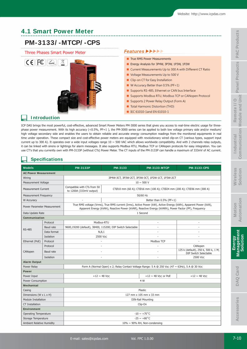
PAC Products
7-10E-mail: [email protected] Vol. FPC 1.0.00
Website: http://www.icpdas.com
PA
C P
rodu
cts
Pan
el P
rodu
cts
Rem
ote
I/O
M
odul
e an
d U
nit
DA
Q C
ard
Indu
stri
al
Com
mun
icat
ion
Wir
eles
s So
luti
onM
otio
n
Au
tom
atio
nEn
ergy
M
anag
emen
tSo
luti
onA
cces
sori
es
4.1 Smart Power Meter
Features True RMS Power Measurements
Energy Analysis for 3P4W, 3P3W, 1P3W, 1P2W
Current Measurements Up to 300 A with Different CT Ratio
Voltage Measurements Up to 500 V
Clip-on CT for Easy Installation
W Accuracy Better than 0.5% (PF=1)
Supports RS-485, Ethernet or CAN bus Interface
Supports Modbus RTU, Modbus TCP or CANopen Protocol
Supports 2 Power Relay Output (Form A)
Total Harmonic Distortion (THD)
IEC 61010-1and EN 61010-1
Introduction
Specifi cations
Models PM-3133P PM-3133 PM-3133-MTCP PM-3133-CPS
AC Power Measurement
Wiring 3P4W-3CT, 3P3W-2CT, 3P3W-3CT, 1P2W-1CT, 1P3W-2CT
Measurement Voltage 10 ~ 500 V
Measurement CurrentCompatible with CTs from 50
to 1200A (333mV output)CTØ10 mm (60 A); CTØ16 mm (100 A); CTØ24 mm (200 A); CTØ36 mm (300 A)
Measurement Frequency 50/60 Hz
W Accuracy - Better than 0.5% (PF=1)
Power Parameter MeasurementTrue RMS voltage (Vrms), True RMS current (Irms), Active Power (kW), Active Energy (kWh), Apparent Power (kVA),
Apparent Energy (kVAh), Reactive Power (kVAR), Reactive Energy (kVARh), Power Factor (PF), Frequency
Data Update Rate 1 Second
Communication
RS-485
Protocol Modbus-RTU - -
Baud rate 9600,19200 (default), 38400, 115200; DIP Switch Selectable - -
Data format N,8,1 - -
Isolation 2500 VDC - -
Ethernet (PoE) Protocol - Modbus TCP -
CANopen
Protocol - - CANopen
Baud rate - - 125 k (default), 250 k, 500 k, 1 M;DIP Switch Selectable
Isolation - - 2500 VDC
Alarm Output
Power Relay Form A (Normal Open) x 2; Relay Contact Voltage Range: 5 A @ 250 VAC (47 ~ 63Hz), 5 A @ 30 VDC
Power
Power Input +12 ~ 48 VDC +12 ~ 48 VDC or PoE +12 ~ 48 VDC
Power Consumption 4 W
Mechanical
Casing Plastic
Dimensions (W x L x H) 127 mm x 105 mm x 33 mm
Module Installation DIN-Rail Mounting
CT Installation Clip-On
Environment
Operating Temperature -10 ~ +70˚C
Storage Temperature -25 ~ +80˚C
Ambient Relative Humidity 10% ~ 90% RH, Non-condensing
ICP DAS brings the most powerful, cost-effective, advanced Smart Power Meters PM-3000 series that gives you access to real-time electric usage for three-phase power measurement. With its high accuracy (<0.5%, PF=1 ), the PM-3000 series can be applied to both low voltage primary side and/or medium/high voltage secondary side and enables the users to obtain reliable and accurate energy consumption readings from the monitored equipments in real time under operation. These compact size and cost-effective power meters are equipped with revolutionary wired clip-on CT (various types, support input current up to 300 A). It operates over a wide input voltages range 10 ~ 500 VAC which allows worldwide compatibility. And with 2 channels relay outputs, it can be linked with sirens or lightings for alarm messages. It also supports Modbus RTU, Modbus TCP or CANopen protocols for easy integration. You can use CT's that you currently own with PM-3133P (without CTs) Power Meter. The CT inputs of the PM-3133P can handle a maximum of 333mV of AC current.
PM-3133/-MTCP/-CPSThree Phases Smart Power Meter
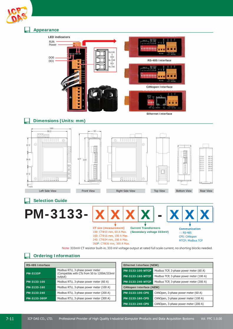
PAC Products
7-11 ICP DAS CO., LTD. Professional Provider of High Quality Industrial Computer Products and Data Acquisition Systems Vol. FPC 1.0.00
Appearance
Ordering Information
Dimensions (Units: mm)
Selection Guide
RS-485 Interface
PM-3133PModbus RTU, 3-phase power meter (Compatible with CTs from 50 to 1200A/333mV output)
PM-3133-100 Modbus RTU, 3-phase power meter (60 A)
PM-3133-160 Modbus RTU, 3-phase power meter (100 A)
PM-3133-240 Modbus RTU, 3-phase power meter (200 A)
PM-3133-360P Modbus RTU, 3-phase power meter (300 A)
Ethernet Interface (NEW)
PM-3133-100-MTCP Modbus TCP, 3-phase power meter (60 A)
PM-3133-160-MTCP Modbus TCP, 3-phase power meter (100 A)
PM-3133-240-MTCP Modbus TCP, 3-phase power meter (200 A)
CANopen Interface (NEW)
PM-3133-100-CPS CANOpen, 3-phase power meter (60 A)
PM-3133-160-CPS CANOpen, 3-phase power meter (100 A)
PM-3133-240-CPS CANOpen, 3-phase power meter (200 A)
PM-3133- -CT size (measurement)100: CTΦ10 mm, 60 A Max.160: CTΦ16 mm, 100 A Max.240: CTΦ24 mm, 200 A Max.360P: CTΦ36 mm, 300 A Max.
Current Transformers(Secondary voltage 333mV)
Communication: RS-485CPS: CANopenMTCP: Modbus TCP
x xx x xx x
Note: 333mV CT resistor built-in, 333 mV voltage output at rated full scale current, no shorting blocks needed.
PowerRUN
LED indicators
DO1DO0
RS-485 Interface
CANopen Interface
Ethernet Interface
33
6.5
10090.0
37.2
35.6
37.2
110127
Bottom View Rear ViewLeft Side View Front View Top ViewRight Side View

PAC Products
7-12E-mail: [email protected] Vol. FPC 1.0.00
Website: http://www.icpdas.com
PA
C P
rodu
cts
Pan
el P
rodu
cts
Rem
ote
I/O
M
odul
e an
d U
nit
DA
Q C
ard
Indu
stri
al
Com
mun
icat
ion
Wir
eles
s So
luti
onM
otio
n
Au
tom
atio
nEn
ergy
M
anag
emen
tSo
luti
onA
cces
sori
es
Models PM-3112 PM-3114 PM-3112-MTCP PM-3114-MTCP PM-3112-CPS PM-3114-CPS
AC Power Measurement
Wiring 1P2W-2CT 1P4W-4CT 1P2W-2CT 1P4W-4CT 1P2W-2CT 1P4W-4CT
Input Voltage 10 ~ 300 V
Input Current CTØ10 mm (60 A); CTØ16 mm (100 A); CTØ24 mm (200 A)
Input Frequency 50/60 Hz
W Accuracy Better than 0.5% (PF=1)
Starting Current >0.03A ( 60A ), >0.05A (100A ), >0.09A( 200A )
Power Parameter Measurement True RMS voltage (Vrms), True RMS current (Irms), Active Power (kW), Active Energy (kWh), Apparent Power (kVA), Apparent Energy (kVAh), Reactive Power (kVAR), Reactive Energy (kVARh), Power Factor (PF)
Data Update Rate 1 Second
Communication
RS-485
Protocol Modbus-RTU - -
Baud rate 9600,19200 (default), 38400, 115200; DIP Switch Selectable - -
Data format N,8,1 - -
Isolation 2500 VDC - -
Ethernet Protocol - Modbus TCP -
CAN BusProtocol - - CANopen
Baud rate - -125 k (default), 250 k, 500 k, 1 M;
DIP Switch Selectable
Alarm Output
Power Relay Form A (Normal Open) x 2; Relay Contact Voltage Range: 5 A @ 250 VAC (47 ~ 63 Hz), 5 A @ 30 VDC
Power
Input Range +12 ~ 48 VDC
Power Consumption 2 W
Mechanical
Casing Plastic
Dimensions (W x L x H) 127 mm x 105 mm x 33 mm
Module Installation DIN-Rail Mounting
CT Installation Clip-On
Environment
Operating Temperature -10 ~ +70˚C
Storage Temperature -25 ~ +80˚C
Ambient Relative Humidity 10% ~ 90% RH, Non-condensing
PM-3112 PM-3114
Features True RMS Power Measurements
Energy Analysis for 1P2W, 1P4W
Current Measurements Up to 200 A with Different CT Ratio
Voltage Measurements Up to 300 V
Clip-on CT for Easy Installation
W Accuracy Better than 0.5% (PF=1)
Supports RS-485, Ethernet or CAN bus Interface
Supports Modbus RTU, Modbus TCP or CANopen Protocol
Supports 2 Power Relay Output (Form A)
IEC 61010-1and EN 61010-1
Introduction
Specifi cations
ICP DAS brings the most powerful, cost-effective, advanced Smart Power Meters PM-3000 series that gives you access to real-time electric usage for single-phase power measurement. With its high accuracy (< 0.5%, PF=1 ), the PM-3000 series can be applied to both low voltage primary side and/or medium/high voltage secondary side and enables the users to obtain reliable and accurate energy consumption readings from the monitored equipments in real time under operation. These compact size and cost-effective power meters are equipped with revolutionary wired clip-on CT (various types, support input current up to 200 A). It operates over a wide input voltages range 10 ~ 300 VAC which allows worldwide compatibility. And with 2 channels relay outputs, it can be linked with sirens or lightings for alarm messages. It also supports Modbus RTU, Modbus TCP or CANopen protocols for easy integration.
PM-3112/-MTCP/-CPSPM-3114/-MTCP/-CPSSingle Phase Smart Power Meter
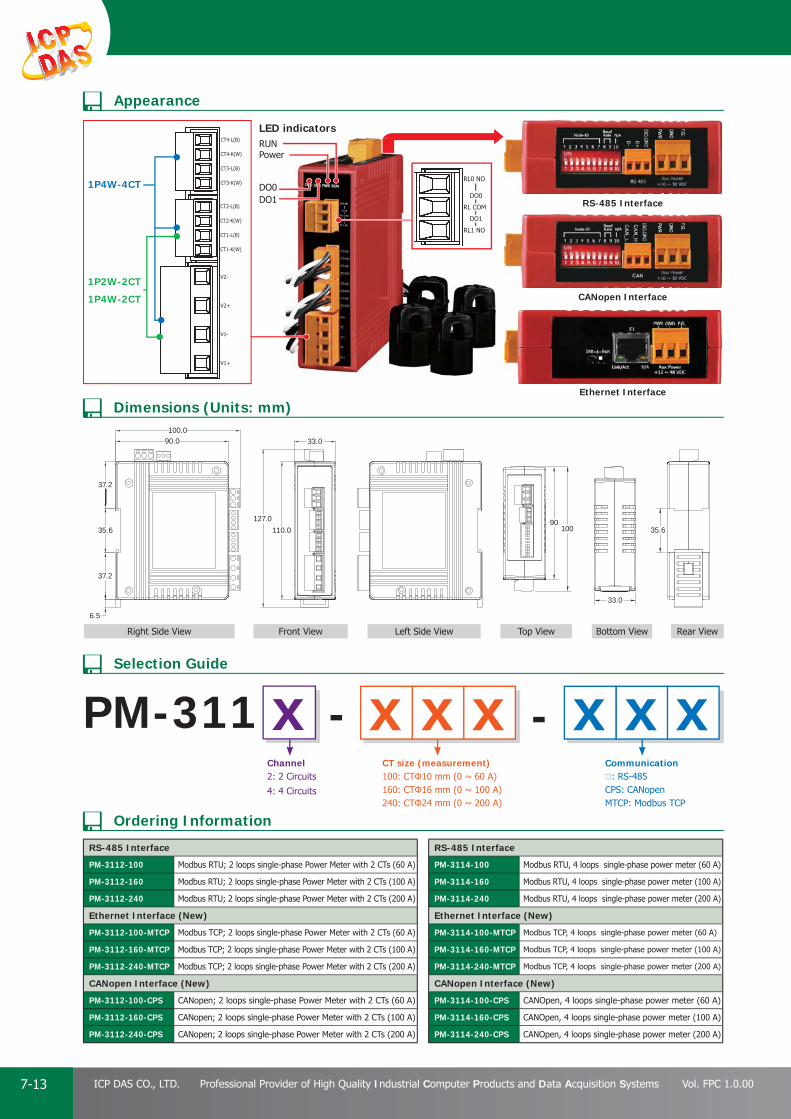
PAC Products
7-13 ICP DAS CO., LTD. Professional Provider of High Quality Industrial Computer Products and Data Acquisition Systems Vol. FPC 1.0.00
PowerRUN
LED indicators
1P2W-2CT
1P4W-2CT
1P4W-4CTDO1DO0
110.0127.0
33.090.0100.0
37.2
35.6
37.2
6.5
35.6
33.0
10090
PM-311Channel2: 2 Circuits
4: 4 Circuits
--xCT size (measurement)100: CTΦ10 mm (0 ~ 60 A)160: CTΦ16 mm (0 ~ 100 A)240: CTΦ24 mm (0 ~ 200 A)
Communication: RS-485CPS: CANopenMTCP: Modbus TCP
RS-485 Interface
CANopen Interface
Ethernet Interface
x xx xx x
RS-485 Interface
PM-3112-100 Modbus RTU; 2 loops single-phase Power Meter with 2 CTs (60 A)
PM-3112-160 Modbus RTU; 2 loops single-phase Power Meter with 2 CTs (100 A)
PM-3112-240 Modbus RTU; 2 loops single-phase Power Meter with 2 CTs (200 A)
Ethernet Interface (New)
PM-3112-100-MTCP Modbus TCP; 2 loops single-phase Power Meter with 2 CTs (60 A)
PM-3112-160-MTCP Modbus TCP; 2 loops single-phase Power Meter with 2 CTs (100 A)
PM-3112-240-MTCP Modbus TCP; 2 loops single-phase Power Meter with 2 CTs (200 A)
CANopen Interface (New)
PM-3112-100-CPS CANopen; 2 loops single-phase Power Meter with 2 CTs (60 A)
PM-3112-160-CPS CANopen; 2 loops single-phase Power Meter with 2 CTs (100 A)
PM-3112-240-CPS CANopen; 2 loops single-phase Power Meter with 2 CTs (200 A)
RS-485 Interface
PM-3114-100 Modbus RTU, 4 loops single-phase power meter (60 A)
PM-3114-160 Modbus RTU, 4 loops single-phase power meter (100 A)
PM-3114-240 Modbus RTU, 4 loops single-phase power meter (200 A)
Ethernet Interface (New)
PM-3114-100-MTCP Modbus TCP, 4 loops single-phase power meter (60 A)
PM-3114-160-MTCP Modbus TCP, 4 loops single-phase power meter (100 A)
PM-3114-240-MTCP Modbus TCP, 4 loops single-phase power meter (200 A)
CANopen Interface (New)
PM-3114-100-CPS CANOpen, 4 loops single-phase power meter (60 A)
PM-3114-160-CPS CANOpen, 4 loops single-phase power meter (100 A)
PM-3114-240-CPS CANOpen, 4 loops single-phase power meter (200 A)
Ordering Information
Dimensions (Units: mm)
Selection Guide
Appearance
Bottom View Rear ViewRight Side View Front View Top ViewLeft Side View

PAC Products
7-14E-mail: [email protected] Vol. FPC 1.0.00
Website: http://www.icpdas.com
PA
C P
rodu
cts
Pan
el P
rodu
cts
Rem
ote
I/O
M
odul
e an
d U
nit
DA
Q C
ard
Indu
stri
al
Com
mun
icat
ion
Wir
eles
s So
luti
onM
otio
n
Au
tom
atio
nEn
ergy
M
anag
emen
tSo
luti
onA
cces
sori
es
8 three phase circuits or 24 single phase circuit
True RMS Power Measurements
Energy Analysis for 3P4W, 3P3W, 1P3W, 1P2W
Current Measurements Up to 300 A with Different CT Ratio
Voltage Measurements Up to 500 V
Clip-on CT for Easy Installation
W Accuracy Better than 0.5% (PF=1)
Supports RS-485, Ethernet or CAN bus Interface
Supports Modbus RTU, Modbus TCP or CANopen Protocol
Supports 2 Power Relay Output (Form A)
Introduction
Models PM-4324 PM-4324-MTCP PM-4324-CPS
AC Power Measurement
Wiring 3P4W-3CT, 3P3W-2CT, 3P3W-3CT, 1P2W-1CT, 1P3W-2CT
Measurement Voltage 10 ~ 500 V
Measurement Current CTØ10 mm (60 A); CTØ16 mm (100 A); CTØ24 mm (200 A); CTØ36 mm (300 A)
Measurement Frequency 50/60 Hz
W Accuracy Better than 0.5% (PF=1)
Power Parameter Measurement True RMS voltage (Vrms), True RMS current (Irms), Active Power (kW), Active Energy (kWh), Apparent Power (kVA), Apparent Energy (kVAh),Reactive Power (kVAR), Reactive Energy (kVARh), Power Factor (PF), Frequency
Data Update Rate 1 Second
Communication
RS-485
Protocol Modbus-RTU - -
Baud rate 9600,19200 (default), 38400, 115200;DIP Switch Selectable - -
Data format N,8,1 - -
Isolation 2500 VDC - -
Ethernet (PoE) Protocol - Modbus TCP -
CAN Bus
Protocol - - CANopen
Baud rate - -125 k (default), 250 k, 500 k, 1 M;
DIP Switch Selectable
Isolation - - 2500 VDC
Alarm Output
Power Relay Form A (Normal Open) x 2; Relay Contact Voltage Range: 5 A @ 250 VAC (47 ~ 63 Hz), 5 A @ 30 VDC
Power
Input Range +90 ~ +240 VAC
Power Consumption 4 W
Mechanical
Casing Plastic
Dimensions (W x L x H) 237 mm x 52 mm x 134 mm
Module Installation DIN-Rail Mounting
CT Installation Clip-On
Environment
Operating Temperature -20 ~ +70˚C
Storage Temperature -25 ~ +80˚C
Ambient Relative Humidity 10% ~ 90% RH, Non-condensing
Specifi cations
The PM-4324 Multi-Channel Power Meter up to 8 three phase circuits or 24 single phase circuits, or any combination of single or three phase circuits. The PM-4324 can measure up to 24 currents via external Current Transformers (CTs). This fl exibility makes the PM-4324 perfect for multitenant facilities such as residential projects, offi ce buildings and shopping malls. This compact instrument is designed to easily fi t into existing panel boards or be fl ush mounted nearby, thus eliminating the need for expensive retrofi t projects or for allocating extra space for the device.
Features
PM-4324Multi-Channel Power Meter

PAC Products
7-15 ICP DAS CO., LTD. Professional Provider of High Quality Industrial Computer Products and Data Acquisition Systems Vol. FPC 1.0.00
Ordering Information
Selection Guide
RS-485 Interface
PM-4324PModbus RTU, 3-phase power meter (Compatible with CTs from 50 to 1200A/333mV output)
PM-4324-100 Modbus RTU, Multi-Channel Power Meter (60 A)
PM-4324-160 Modbus RTU, Multi-Channel Power Meter (100 A)
PM-4324-240 Modbus RTU, Multi-Channel Power Meter(200 A)
PM-4324-360P Modbus RTU, Multi-Channel Power Meter (300 A)
Ethernet Interface
PM-4324-100-MTCP Modbus TCP, Multi-Channel Power Meter (60 A)
PM-4324-160-MTCP Modbus TCP, Multi-Channel Power Meter (100 A)
PM-4324-240-MTCP Modbus TCP, Multi-Channel Power Meter (200 A)
CANopen Interface
PM-4324-100-CPS CANOpen, Multi-Channel Power Meter (60 A)
PM-4324-160-CPS CANOpen, Multi-Channel Power Meter (100 A)
PM-4324-240-CPS CANOpen, Multi-Channel Power Meter (200 A)
PM-4324- -CT size (measurement)100: CTΦ10 mm, 60 A Max.160: CTΦ16 mm, 100 A Max.240: CTΦ24 mm, 200 A Max.360P: CTΦ36 mm, 300 A Max.
Current Transformers(Secondary voltage 333mV)
Communication: RS-485CPS: CANopenMTCP: Modbus TCP
x xx x xx x
Note: 333mV CT resistor built-in, 333 mV voltage output at rated full scale current, no shorting blocks needed.
Appearance
Dimensions (Units: mm)
112.6
180214.6
237
123134
52
44.8
35.5
53.8
Rear View
Bottom View
Left Side View Front View
Top View
Right Side View
12CTs (CH1~4) for 3-phase /
12CTs (CH1~12) for single-phase
AC Measurement
(1 reference voltage)
10 ~ 500 V (A, B, C, N)
12CTs (CH5~8) for 3-phase /
12CTs (CH13~24) for single-phaseAux. Power Input
85 ~ 264 VAC/120 ~ 370 VDC
RS-485
2-CH Relay outputNode ID
Baud rate

PAC Products
7-16E-mail: [email protected] Vol. FPC 1.0.00
Website: http://www.icpdas.com
PA
C P
rodu
cts
Pan
el P
rodu
cts
Rem
ote
I/O
M
odul
e an
d U
nit
DA
Q C
ard
Indu
stri
al
Com
mun
icat
ion
Wir
eles
s So
luti
onM
otio
n
Au
tom
atio
nEn
ergy
M
anag
emen
tSo
luti
onA
cces
sori
es
The M-7017RMS is an 8-channel differential AC input module that is used to convert the AC input signals to their True RMS DC values. The RMS input range can be from +150 mVrms to +10 Vrms, and each channel can be confi gured individually. The M-7017RMS is a complete, high-accuracy, RMS-to-DC converter that computes the True RMS DC value of any complex waveform. It also features 4 kV ESD protection, 2500 VDC intra-module isolation and +/-35 VDC overvoltage protection.
Model M-7017RMSCommunication
Interface RS-485
Bias ResistorNo (Usually supplied by the RS-485 Master. Alternatively,
add a tM-SG4 or SG-785.)
Baud Rate 1200 to 115200 bps
Protocol Modbus RTU, DCON
Dual Watchdog Yes, Module (1.6 Seconds), Communication (Programmable)
LED Indicators/Display
System LED Indicator Yes, 1 as Power/Communication Indicator
I/O LED Indicators -
7-segment LED Display -
Isolation
Intra-module Isolation, Field-to-Logic
2500 VDC
EMS Protection
ESD (IEC 61000-4-2)±4 kV Contact for each Terminal
±8 kV Air for Random Point
EFT (IEC 61000-4-4) ±4 kV for Power Line
Surge (IEC 61000-4-5) ±0.5 kV for Power Line
Power
Reverse Polarity Protection Yes
Input +10 ~ +30 VDC
Consumption 0.9 W
Mechanical
Dimensions (L x W x H) 123 mm x 72 mm x 35 mm
Installation DIN-Rail
Environment
Operating Temperature -25 to +75°C
Storage Temperature -40 to +85°C
Humidity 10 to 95% RH, Non-condensing
Model M-7017RMSAnalog Input
Channels 8
Wiring Differential
Input Range0 ~ +10 Vrms, 0 ~ +5 Vrms, 0 ~ +1 Vrms,
0 ~ +500 mVrms, 0 ~ +150 mVrms
Resolution 16-bit
Accuracy
Sinusoid
50/60 Hz ±0.15% of FSR
45 Hz to 10 kHz ±0.5% of FSR
Non-Sinusoid
Crest Factor = 1 to 2 ±0.2% of FSR
Crest Factor = 2 to 3 ±0.35% of FSR
DC
0 ~ +10 Vrms/ 0 ~ +5 Vrms/ 0 ~ +1 Vrms,
±0.3% of FSR
Other ±0.7% of FSR
Sampling Rate 10 Hz (Total)
-3dB Bandwidth 15.7 Hz
Zero Drift ±20 μV/°C
Span Drift ±25 ppm/°C
Common Mode Rejection 86 dB
Normal Mode Rejection 100 dB
Input Impedance >2 MΩ
Individual Channel Confi guration Yes
Overvoltage Protection ±35 VDC
• Building Automation
• Factory Automation
• Machine Automation
• Remote Maintenance
4.2 True RMS Input Module
Features 8-channel True RMS Input
±0.15% Factory Calibrated Accuracy
The RMS input range can be from +150 mVrms to +10 Vrms
Designed for Standard Operation with Frequencies of 45 Hz to 10 KHz
Individual Channel Confi gurable
4 kV ESD Protection
±35 VDC Overvoltage Protection
2500 VDC Intra-module Isolation
RoHS Compliant
Wide Operating Temperature Range: -25 to +75°C
M-7017RMS8-channel True RMS Input Module
Introduction
System Specifi cations
I/O Specifi cations
Applications
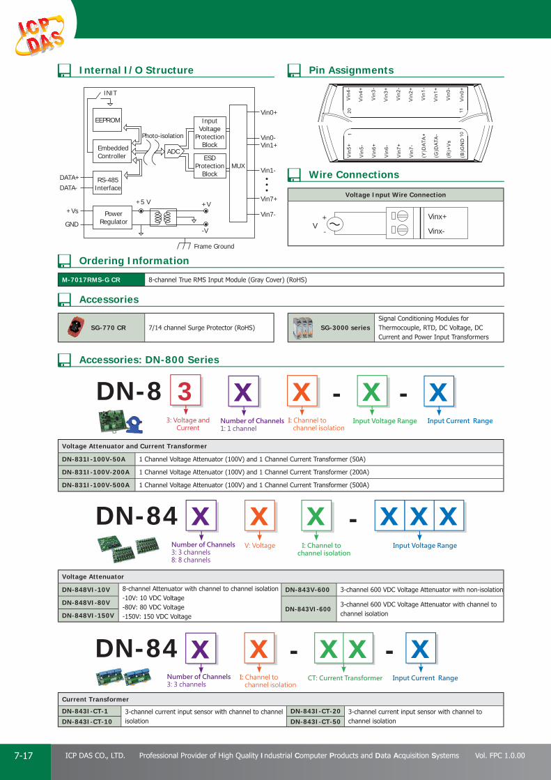
PAC Products
7-17 ICP DAS CO., LTD. Professional Provider of High Quality Industrial Computer Products and Data Acquisition Systems Vol. FPC 1.0.00
Voltage Input Wire Connection
Vinx+
Vinx-V
+
-
M-7017RMS-G CR 8-channel True RMS Input Module (Gray Cover) (RoHS)
+Vs+5 V
DATA+
EEPROM
EmbeddedController
InputVoltage
ProtectionBlock
ESDProtection
BlockRS-485
Interface
PowerRegulator
ADC
MUX
INIT
GND
+V
-V
Photo-isolation
Frame Ground
DATA-
Vin0+
Vin0-Vin1+
Vin1-
Vin7+
Vin7-
SG-770 CR 7/14 channel Surge Protector (RoHS) SG-3000 seriesSignal Conditioning Modules for Thermocouple, RTD, DC Voltage, DC Current and Power Input Transformers
Voltage Attenuator
DN-848VI-10V 8-channel Attenuator with channel to channel isolation-10V: 10 VDC Voltage-80V: 80 VDC Voltage-150V: 150 VDC Voltage
DN-843V-600 3-channel 600 VDC Voltage Attenuator with non-isolation
DN-848VI-80VDN-843VI-600
3-channel 600 VDC Voltage Attenuator with channel to channel isolationDN-848VI-150V
Voltage Attenuator and Current Transformer
DN-831I-100V-50A 1 Channel Voltage Attenuator (100V) and 1 Channel Current Transformer (50A)
DN-831I-100V-200A 1 Channel Voltage Attenuator (100V) and 1 Channel Current Transformer (200A)
DN-831I-100V-500A 1 Channel Voltage Attenuator (100V) and 1 Channel Current Transformer (500A)
Current Transformer
DN-843I-CT-1 3-channel current input sensor with channel to channel isolation
DN-843I-CT-20 3-channel current input sensor with channel to channel isolationDN-843I-CT-10 DN-843I-CT-50
DN-8Number of Channels1: 1 channel
Number of Channels3: 3 channels8: 8 channels
Number of Channels3: 3 channels
3: Voltage and Current
--x3I: Channel to channel isolation
Input Voltage Range Input Current Range
x xx
x xxDN-84 -xV: Voltage I: Channel to
channel isolationInput Voltage Range
xx
xDN-84 --xCT: Current Transformer Input Current Range
x xxI: Channel to channel isolation
Internal I/O Structure Pin Assignments
Wire Connections
Ordering Information
Accessories: DN-800 Series
Accessories

PAC Products
7-18E-mail: [email protected] Vol. FPC 1.0.00
Website: http://www.icpdas.com
PA
C P
rodu
cts
Pan
el P
rodu
cts
Rem
ote
I/O
M
odul
e an
d U
nit
DA
Q C
ard
Indu
stri
al
Com
mun
icat
ion
Wir
eles
s So
luti
onM
otio
n
Au
tom
atio
nEn
ergy
M
anag
emen
tSo
luti
onA
cces
sori
es
5. Applications
BuildingICP DAS power monitoring and management solution is perfect for large-scale power monitoring for buildings. A PMC can be installed on each fl oor and connect to ICP DAS smart power meters via RS-485 or Ethernet interface to measure the power information of air conditioning, lighting, drainage or other electrical devices. The power information of the devices such as voltage, current and kilowatt information will be recorded in real-time and the data can be transmitted to back-end control center. With SCADA software, it can perform data gathering and analysis of the power data. By collecting electricity data, analyzing electricity data, identifying the problems and correcting improper behaviors on the electricity usage, the effi ciency of power usage can be enhanced and furthermore, ensure stable power supply and energy saving.
FactoryElectr ic i ty consumpt ion a lways p lays an important role in factory operations. With the limited availability of the energy sources, countries all over the world all seek to enforce legal regulations in energy saving and carbon reduction; as the cost of energy is getting higher and higher, any factories in the world are paying more attention to energy and resources optimization. For effective usage of the energy not only reduce the electricity cost but also stabilize the power system to maintain the normal operation of the production line.
The PMC developed by ICP DAS is perfect for building a power monitoring system for factory applications. It will send out real-time notifi cation when there is unusual electricity consumption, and will perform load shedding in real time when the forecast capacity is going to exceed the contract capacity to avoid penalties. And by working with SCADA software, it enables gathering and analysis of the power data to design best power policy to enhance the effi ciency of power supply.

PAC Products
7-19 ICP DAS CO., LTD. Professional Provider of High Quality Industrial Computer Products and Data Acquisition Systems Vol. FPC 1.0.00
Electricity Consumption of MachinesIn order to ensure the stability and reliability of the machines; usually it requires the monitoring of electricity consumption. The purpose is not only for energy saving, but also to investigate the infl uence of electric current variation that may affect the yield rate of the prod-ucts during the production process. For most machines uses both AC and DC power supply, if the traditional power meters are used, it may requires several power meters to implement the monitoring jobs. By using M-7017RMS, it can monitor multiple circuits at the same time and support both AC and DC current monitoring; so that it will save the installation space and no need to install lots modules for individual functions.
Multi-circuit Meter DisplayICP DAS Smart Power Meter with the compact size provides high-quality measurement accuracy. If customers need to display the power data in the fi eld side, ICP DAS provides the power numerical display solutions, such as using a VPD of the TouchPAD series with our power meter products. Through the communication mechanism, the data of the multiple power meters can be presented on the screen of one VPD, customers can provide this solution in the local end. Furthermore, the data can be integrated into the background SCADA control system, not only to get the power information, but also to facilitate the integration and confi guration. Most multi-circuit meters are often diffi cult to display the numerical data in the local end, but our VPD products can provide the multi-circuit power information on one device by switching the page, so that the offi cer in the fi eld side can quickly understand the current state.

Introduction P 8-1
ISA Bus Data Acquisition Boards P 8-133
PCI Bus Data Acquisition Boards P 8-62
● 2.1 Multi-Function Boards - - - - - - - - - - - - - - - - - - - - - - - - - - - - - - - - P 8-6
● 2.2 Memory Boards - - - - - - - - - - - - - - - - - - - - - - - - - - - - - - - - - - - - P 8-10
● 2.3 Analog Output Boards - - - - - - - - - - - - - - - - - - - - - - - - - - - - - - - - P 8-10
● 2.4 Non-Isolated Digital I/O Boards - - - - - - - - - - - - - - - - - - - - - - - - - - P 8-11
● 2.5 Isolated Digital I/O Boards - - - - - - - - - - - - - - - - - - - - - - - - - - - - - P 8-12
PCI Express Data Acquisition Boards P 8-31
● 1.1. Analog I/O Boards - - - - - - - - - - - - - - - - - - - - - - - - - - - - - - - - - - P 8-3
● 1.2. Digital I/O Boards- - - - - - - - - - - - - - - - - - - - - - - - - - - - - - - - - - - P 8-5
DAQ CardDAQ CardDAQ Card
ISA Bus Data Acquisition Boards P 8-133
8
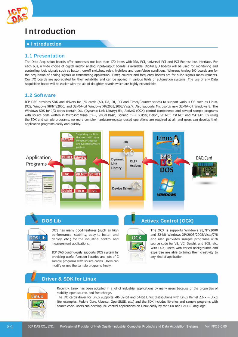
PAC Products
8-1 ICP DAS CO., LTD. Professional Provider of High Quality Industrial Computer Products and Data Acquisition Systems Vol. FPC 1.0.00
● Introduction
Introduction
1.1 PresentationThe Data Acquisition boards offer comprises not less than 170 items with ISA, PCI, universal PCI and PCI Express bus interface. For each bus, a wide choice of digital and/or analog input/output boards is available. Digital I/O boards will be used for monitoring and controlling logic signals such as button, on/off switches, relay, high/low and open/close conditions. Whereas Analog I/O boards are for the acquisition of analog signals or transmitting application. Timer, counter and frequency boards are for pulse signals measurements. Our I/O boards are appreciated for their reliability, and can be applied in various fi elds of automation systems. The use of any Data Acquisition board will be easier with the aid of daughter boards which are highly expandable.
1.2 SoftwareICP DAS provides SDK and drivers for I/O cards (AD, DA, DI, DO and Timer/Counter series) to support various OS such as Linux, DOS, Windows 98/NT/2000, and 32-/64-bit Windows XP/2003/2008/Vista/7. Also supports Microsoft’s new 32-/64-bit Windows 8. The Windows SDK for I/O cards contain DLL (Dynamic Link Library) fi le, ActiveX (OCX) control components and several sample programs with source code written in Microsoft Visual C++, Visual Basic, Borland C++ Builder, Delphi, VB.NET, C#.NET and MATLAB. By using the SDK and sample programs, no more complex hardware-register-based operations are required at all, and users can develop their application programs easily and quickly.
DAQ Card
Device Driver
.LIB
DynamicLink Library
OLE/
Delphi BCB VB
VC VB.NET VC.NET
C#.NET LabVIEW
MATLAB
DOS has many good features (such as high performance, stability, easy to install and deploy, etc.) for the industrial control and measurement applications.
ICP DAS continuously supports DOS system by providing useful function libraries and lots of C sample programs with source codes. Users can modify or use the sample programs freely.
The OCX is supports Windows 98/NT/2000 and 32-bit Windows XP/2003/2008/Vista/7/8 and also provides sample programs with source code for VB, VC, Delphi, and BCB, etc. With OCX, users with varied backgrounds and expertise are able to bring their creativity to any kind of application.
Recently, Linux has been adopted in a lot of industrial applications by many users because of the properties of stability, open source, and free charge.The I/O cards driver for Linux supports x86 32-bit and 64-bit Linux distributions with Linux Kernel 2.6.x ~ 3.x.x (for examples, Fedora Core, Ubuntu, OpenSUSE, etc.) and the SDK includes libraries and sample programs with source code. Users can develop I/O control applications on Linux easily by the SDK and GNU C Language.
DOS Lib Activex Control (OCX)
Driver & SDK for Linux
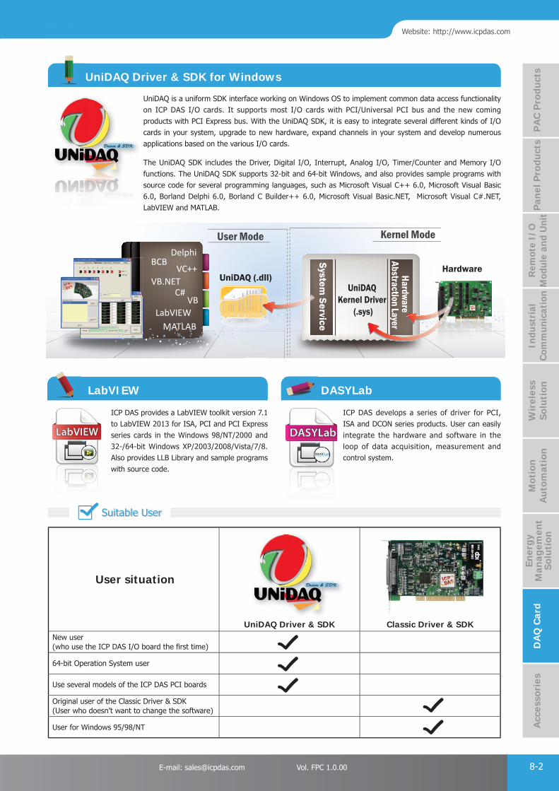
PAC Products
8-2E-mail: [email protected] Vol. FPC 1.0.00
Website: http://www.icpdas.com
PA
C P
rodu
cts
Pan
el P
rodu
cts
Rem
ote
I/O
M
odul
e an
d U
nit
DA
Q C
ard
Indu
stri
al
Com
mun
icat
ion
Wir
eles
s So
luti
onM
otio
n
Au
tom
atio
nA
cces
sori
esEn
ergy
M
anag
emen
tSo
luti
on
ICP DAS provides a LabVIEW toolkit version 7.1 to LabVIEW 2013 for ISA, PCI and PCI Express series cards in the Windows 98/NT/2000 and 32-/64-bit Windows XP/2003/2008/Vista/7/8. Also provides LLB Library and sample programs with source code.
ICP DAS develops a series of driver for PCI, ISA and DCON series products. User can easily integrate the hardware and software in the loop of data acquisition, measurement and control system.
DelphiBCB
VC++VB.NET
VBC#
LabVIEWMATLAB
UniDAQ (.dll)Hardware
System Service
UniDAQ Kernel Driver
(.sys)
Hardware Abstraction Layer
Kernel ModeUser Mode
AAT
UniDAQ is a uniform SDK interface working on Windows OS to implement common data access functionality on ICP DAS I/O cards. It supports most I/O cards with PCI/Universal PCI bus and the new coming products with PCI Express bus. With the UniDAQ SDK, it is easy to integrate several different kinds of I/O cards in your system, upgrade to new hardware, expand channels in your system and develop numerous applications based on the various I/O cards.
The UniDAQ SDK includes the Driver, Digital I/O, Interrupt, Analog I/O, Timer/Counter and Memory I/O functions. The UniDAQ SDK supports 32-bit and 64-bit Windows, and also provides sample programs with source code for several programming languages, such as Microsoft Visual C++ 6.0, Microsoft Visual Basic 6.0, Borland Delphi 6.0, Borland C Builder++ 6.0, Microsoft Visual Basic.NET, Microsoft Visual C#.NET, LabVIEW and MATLAB.
LabVIEW DASYLab
UniDAQ Driver & SDK for Windows
Suitable User
User situation
UniDAQ Driver & SDK Classic Driver & SDKNew user(who use the ICP DAS I/O board the fi rst time)
64-bit Operation System user
Use several models of the ICP DAS PCI boards
Original user of the Classic Driver & SDK(User who doesn’t want to change the software)
User for Windows 95/98/NT

PAC Products
8-3 ICP DAS CO., LTD. Professional Provider of High Quality Industrial Computer Products and Data Acquisition Systems Vol. FPC 1.0.00
1.1 Analog I/O Boards
PCI Express, Analog Output/Input Boards
Model Name PCIe-8620/8622 PEX-1202L PEX-1202H PEX-1002L PEX-1002H PEX-DA4/8/16
Interface PCI Express
Analog Input
Isolation Voltage 3750 Vrms (Bus-type) -
Resolution 16-bit 12-bit 12-bit -
Channels 8/16 S.E 32 S.E./16 Diff. 32 S.E./16 Diff. -
Sampling Rate 200 kS/s (Per Channel) 110 kS/s 44 kS/s 110 kS/s 44 kS/s -
Bipolar Input± 5 V,± 10 V
± 0.625 V, ± 1.25 V, ± 2.5 V,
± 5 V, ± 10 V
± 0.005 V, ± 0.01 V, ± 0.05 V,
± 0.1 V± 1 V, ± 5 V, ± 10 V
± 1.25 V, ± 2.5 V, ± 5 V, ± 10 V
± 0.01 V, ± 0.1 V, ± 1 V, ± 10 V
-
Unipolar Input -
0~10 V, 0~5 V,
0~2.5 V, 0~1.25 V
0~10 V, 0~0.1 V, 0~0.01 V
- - -
FIFO Size 2 K 1 K - -
Accuracy0.05% of FSR ±1 LSB
@ 25°C, ± 10 V0.01% of FSR ±1 LSB @ 25°C, ± 10 V 0.01% of FSR ±1 LSB @ 25°C, ± 10 V -
Analog Output
Resolution - 12-bit - 14-bit
Channels 2 (Only for PCIe-8622) 2 - 4/8/16
Accuracy - 0.06% of FSR ± 1 LSB @ 25°C, ± 10 V -0.04% of FSR ± 2
LSB @ 25°C, ± 10 V
Output Range - ±5 V, ±10 V -Voltage: ± 10 V,
Current: 0 ~ 20 mA
Slew Rate - 8.33 V/μs - 0.71 V/μs
Digital Input
Channels 4/12 16 16 16
Compatibility Isolated (3750 Vrms) 5 V/ TTL 5 V/ TTL 5 V/TTL
Digital Output
Channels 4/12 16 16 16
Compatibility Isolated (3750 Vrms) 5 V/CMOS 5 V/ TTL 5 V/CMOS
Timer/Counter
Channels - 3 3 3
Resolution - 16-bit 16-bit 16-bit
Clock Source - 8 MHz 4 MHz (Internal) 4 MHz (Internal)
NEW NEWNEW
1. PCI Express Data Acquisition Boards
PEX-1202L
Features PCI Express x 1 for PEX-1202L/H
12-bit 110 kHz ADC with Max. 110 kS/s or 44 kS/s sampling rate
32 S.E./ 8 Diff. analog inputs, 1024 samples FIFO
16 digital input and 16 digital output channels.
2-ch 12-bit voltage output
Features PCI Express x1, Low profi le
8/16-ch S.E
8/16-ch Synchronous Sample & Hold
4/12-ch digital output, 4/12-ch digital input
16-bit 200 kHz AD Sampling Rate for all channels
2048-samples hardware FIFO for analog input
2-ch 12-bit voltage output
Ho
igital input
old
it l i t
Available soon
PCIe-8620
PCIe-8622
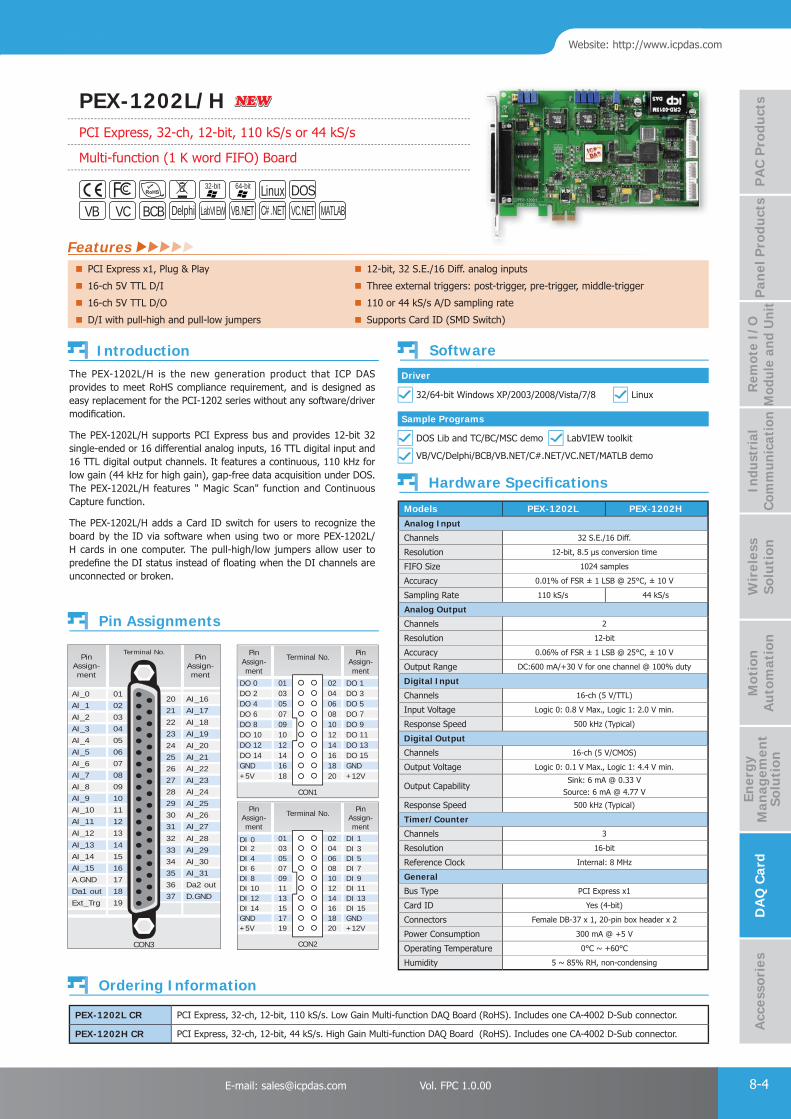
PAC Products
8-4E-mail: [email protected] Vol. FPC 1.0.00
Website: http://www.icpdas.com
PA
C P
rodu
cts
Pan
el P
rodu
cts
Rem
ote
I/O
M
odul
e an
d U
nit
DA
Q C
ard
Indu
stri
al
Com
mun
icat
ion
Wir
eles
s So
luti
onM
otio
n
Au
tom
atio
nA
cces
sori
esEn
ergy
M
anag
emen
tSo
luti
on
Features
PEX-1202L CR PCI Express, 32-ch, 12-bit, 110 kS/s. Low Gain Multi-function DAQ Board (RoHS). Includes one CA-4002 D-Sub connector.
PEX-1202H CR PCI Express, 32-ch, 12-bit, 44 kS/s. High Gain Multi-function DAQ Board (RoHS). Includes one CA-4002 D-Sub connector.
The PEX-1202L/H is the new generation product that ICP DAS provides to meet RoHS compliance requirement, and is designed as easy replacement for the PCI-1202 series without any software/driver modifi cation.
The PEX-1202L/H supports PCI Express bus and provides 12-bit 32 single-ended or 16 differential analog inputs, 16 TTL digital input and 16 TTL digital output channels. It features a continuous, 110 kHz for low gain (44 kHz for high gain), gap-free data acquisition under DOS. The PEX-1202L/H features " Magic Scan" function and Continuous Capture function.
The PEX-1202L/H adds a Card ID switch for users to recognize the board by the ID via software when using two or more PEX-1202L/H cards in one computer. The pull-high/low jumpers allow user to predefi ne the DI status instead of fl oating when the DI channels are unconnected or broken.
Models PEX-1202L PEX-1202HAnalog Input
Channels 32 S.E./16 Diff.
Resolution 12-bit, 8.5 μs conversion time
FIFO Size 1024 samples
Accuracy 0.01% of FSR ± 1 LSB @ 25°C, ± 10 V
Sampling Rate 110 kS/s 44 kS/s
Analog Output
Channels 2
Resolution 12-bit
Accuracy 0.06% of FSR ± 1 LSB @ 25°C, ± 10 V
Output Range DC:600 mA/+30 V for one channel @ 100% duty
Digital Input
Channels 16-ch (5 V/TTL)
Input Voltage Logic 0: 0.8 V Max., Logic 1: 2.0 V min.
Response Speed 500 kHz (Typical)
Digital Output
Channels 16-ch (5 V/CMOS)
Output Voltage Logic 0: 0.1 V Max., Logic 1: 4.4 V min.
Output CapabilitySink: 6 mA @ 0.33 V
Source: 6 mA @ 4.77 V
Response Speed 500 kHz (Typical)
Timer/Counter
Channels 3
Resolution 16-bit
Reference Clock Internal: 8 MHz
General
Bus Type PCI Express x1
Card ID Yes (4-bit)
Connectors Female DB-37 x 1, 20-pin box header x 2
Power Consumption 300 mA @ +5 V
Operating Temperature 0°C ~ +60°C
Humidity 5 ~ 85% RH, non-condensing
01
091012141618
030507
02
101214161820
040608
PinAssign-ment
PinAssign-ment
Terminal No.
DO 0
DO 8DO 10DO 12DO 14GND+5V
DO 2DO 4DO 6
DO 1
DO 9DO 11DO 13DO 15GND+12V
DO 3DO 5DO 7
CON1
01
091113151719
030507
02
101214161820
040608
PinAssign-ment
PinAssign-ment
Terminal No.
DI 8DI 10DI 12DI 14GND+5V
DI 4DI 6
DI 9DI 11DI 13DI 15GND+12V
DI 5DI 7
CON2
DI 0DI 2
DI 1DI 3
AI_14AI_15
A.GND
Da1 out
Ext_Trg
AI_0AI_1
AI_2
AI_3
AI_4
AI_5AI_6
AI_7AI_8AI_9
AI_10
AI_11
AI_12
AI_13AI_29AI_30AI_31
Da2 out
D.GND
AI_16AI_17
AI_18
AI_19
AI_20
AI_21AI_22
AI_23AI_24AI_25
AI_26
AI_27
AI_28
1516
17
18
19
0102
03
04
05
0607
080910
11
12
13
14333435
36
37
2021
22
23
24
2526
272829
30
31
32
PinAssign-ment
PinAssign-ment
CON3
Terminal No.
PCI Express x1, Plug & Play 12-bit, 32 S.E./16 Diff. analog inputs
16-ch 5V TTL D/I Three external triggers: post-trigger, pre-trigger, middle-trigger
16-ch 5V TTL D/O 110 or 44 kS/s A/D sampling rate
D/I with pull-high and pull-low jumpers Supports Card ID (SMD Switch)
DOSVB VC BCB Delphi VB.NET C#.NETLabVIEW
Linux32-bit
VC.NET MATLAB
64-bit
Introduction
Pin Assignments
Hardware Specifi cations
Ordering Information
Software
Sample Programs
DOS Lib and TC/BC/MSC demo LabVIEW toolkit
Driver
32/64-bit Windows XP/2003/2008/Vista/7/8 Linux
VB/VC/Delphi/BCB/VB.NET/C#.NET/VC.NET/MATLB demo
NEWNEWPEX-1202L/HPCI Express, 32-ch, 12-bit, 110 kS/s or 44 kS/s
Multi-function (1 K word FIFO) Board
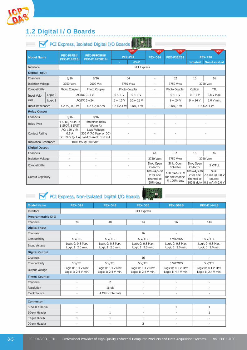
PAC Products
8-5 ICP DAS CO., LTD. Professional Provider of High Quality Industrial Computer Products and Data Acquisition Systems Vol. FPC 1.0.00
PCI Express, Isolated Digital I/O Boards
Model NamePEX-P8R8i/
PEX-P16R16iPEX-P8POR8i/
PEX-P16POR16iPEX-P64 PEX-C64 PEX-P32C32 PEX-730
- -24V Isolated Non-Isolated
Interface PCI Express
Digital Input
Channels 8/16 8/16 64 - 32 16 16
Isolation Voltage 3750 Vrms 2000 VDC 3750 Vrms - 3750 Vrms 3750 Vrms
Compatibility Photo Coupler Photo Coupler Photo Coupler - Photo Coupler Optical TTL
Input Volt-age
Logic 0 AC/DC 0~1 V 0 ~ 1 V 0 ~ 1 V - 0 ~ 1 V 0 ~ 1 V 0.8 V Max.
Logic 1 AC/DC 5 ~24 5 ~ 15 V 20 ~ 28 V 9 ~ 24 V 9 ~ 24 V 2.0 V min.
Input Impedance 1.2 KΩ, 0.5 W 1.2 KΩ, 0.5 W 1.2 KΩ,1 W 3 KΩ, 1 W - 3 KΩ, 5 W 1.2 KΩ, 1 W
Relay Output
Channels 8/16 8/16 - - - -
Relay Type4 SPDT, 4 SPST/8 SPDT, 8 SPST
PhotoMos Relay (Form A)
- - - -
Contact RatingAC: 120 V @
0.5 ADC: 24 V @ 1 A
Load Voltage: 300 V (AC Peak or DC)Load Current: 130 mA
- - - -
Insulation Resistance 1000 MΩ @ 500 VDC - - - -
Digital Output
Channels - - - 64 32 16 16
Isolation Voltage - - - 3750 Vrms 3750 Vrms 3750 Vrms
Compatibility - - -Sink, Open Collector
Sink, Open Collector
Sink, Open Collector
5 V/TLL
Output Capability - - -
100 mA/+30 V for one channel @ 60% duty
100 mA/+30 V for one channel @ 100% duty
100 mA/+30 V for one channel @ 100% duty
Sink: 2.4 mA @ 0.8 V
Source: 0.8 mA @ 2.0 V
Model Name PEX-D24 PEX-D48 PEX-D56 PEX-D96S PEX-D144LS
Interface PCI Express
Programmable DIO
Channels 24 48 24 96 144
Digital Input
Channels - - 16 - -
Compatibility 5 V/TTL 5 V/TTL 5 V/TTL 5 V/CMOS 5 V/TTL
Input VoltageLogic 0: 0.8 Max.Logic 1: 2.0 min.
Logic 0: 0.8 Max.Logic 1: 2.0 min.
Logic 0: 0.8 Max.Logic 1: 2.0 min.
Logic 0: 0.8 Max.Logic 1: 2.0 min.
Logic 0: 0.8 Max.Logic 1: 2.0 min.
Digital Output
Channels - - 16 - -
Compatibility 5 V/TTL 5 V/TTL 5 V/TTL 5 V/CMOS 5 V/TTL
Output VoltageLogic 0: 0.4 V Max.Logic 1: 2.4 V min.
Logic 0: 0.4 V Max.Logic 1: 2.4 V min.
Logic 0: 0.4 V Max.Logic 1: 2.4 V min.
Logic 0: 0.1 V Max.Logic 1: 4.4 V min.
Logic 0: 0.4 V Max.Logic 1: 2.4 V min.
Timer/Counter
Channels - 2 - - -
Resolution - 16-bit - - -
Clock Source - 4 MHz (Internal) - - -
Connector
SCSI II 100-pin - - - 1 1
50-pin Header - 1 - - 1
37-pin D-Sub 1 1 1 - -
20-pin Header - - 2 - -
NEW NEW NEW NEW
PCI Express, Non-Isolated Digital I/O Boards
1.2 Digital I/O Boards
NEWEEEE

PAC Products
8-6E-mail: [email protected] Vol. FPC 1.0.00
Website: http://www.icpdas.com
PA
C P
rodu
cts
Pan
el P
rodu
cts
Rem
ote
I/O
M
odul
e an
d U
nit
DA
Q C
ard
Indu
stri
al
Com
mun
icat
ion
Wir
eles
s So
luti
onM
otio
n
Au
tom
atio
nA
cces
sori
esEn
ergy
M
anag
emen
tSo
luti
on
Model NamePCI-2602U
PCI-826 PCI-822 PCI-1802 PCI-1800 PCI-1602 PCI-1202 PCI-1002 PIO-821PISO-813
LU LU LU HU LU HU U FU LU HU LU HU L H
Interface Universal PCI PCI Bus
Analog Input
Resolution 16-bit 16-bit 12-bit 12-bit 12-bit 16-bit 12-bit 12-bit 12-bit 12-bit
ChannelsS.E. 16 32 32 16 32 32 32 16 32 S.E.
Diff. 8 16 16 8 16 16 16 8 -
Sampling Rate 1 MS/s 250 KS/s330 KS/s
44 KS/s
330 KS/s
44 KS/s
100 KS/s
200 KS/s
110 KS/s
40 KS/s
110 KS/s
44 KS/s
45 KS/s 10 KS/s
FIFO Size 8 K 8 K 8 K 1 K 8 K 1 K - - -
Unipolar Input - - - - -
Bipolar Input
Analog Output
Resolution 16-bit 16-bit 12-bit 12-bit 12-bit 12-bit - 12-bit -
Channels 2 2 2 2 2 2 - 1 -
Output Range (V)
±10, ±5, ±EXT_REF, 0~10, 0~5, 0~EXT_REF
± 5, ± 100 ~ 5, 0 ~ 10
± 5, ± 10 ± 5, ± 10 ± 5, ± 10 ± 5, ± 10 -0~10, 0~5, 0~EXT_REF
-
Digital I/O
DI Channels - - 16 16 16 16 16 16 -
DO Channels - - 16 16 16 16 16 16 -
Programmable DIO Channels
32 32 - - - - - - -
Compatibility 5 V/TTL 5 V/TTL 5 V/TTL 5 V/TTL 5 V/TTL 5 V/TTL 5 V/TTL 5 V/TTL -
Timer/Counter
Channels - - 1 1 1 1 1 3 -
Resolution - - 16-bit 16-bit 16-bit 16-bit 16-bit 16-bit -
Clock Source - - 8 MHz 8 MHz 8 MHz 8 MHz 4 MHz 2 MHz -
2.1 Multi-Function Boards
2. PCI Bus Data Acquisition Boards
Features PCI-2602U
PCI-2602U
Universal PCI(3.3V/5V) Interface
16 S.E./8 Diff. analog inputs, 8192 samples FIFO
16-bit ADC with Max. 1 MS/s sampling rate
2-ch 16-bit voltage output
32-ch programmable DI/DO
8-bit analog/digital pattern generator
Analog/Digital external trigger
NEW

PAC Products
8-7 ICP DAS CO., LTD. Professional Provider of High Quality Industrial Computer Products and Data Acquisition Systems Vol. FPC 1.0.00
Introduction
32-bit 64-bit VB VC BCB Delphi VB.NET C#.NET
Features
NewNew
Universal PCI (3.3 V/5 V) Interface, Plug & Play 16 Single-ended/8 Differential Analog Input Channels
Supports Card ID (SMD Switch) 16-bit ADC with Max. 1 MS/s Sampling Rate
2-channel 16-bit Voltage Output 8192-sample Hardware FIFO for Analog Input 512-sample Hardware FIFO for Analog Pattern Generator AD Trigger Mode: Software Trigger, Post-trigger, Middle-Trigger, 32-channel Programmable DI/O Delay-Trigger
Supports DO Status Readback (Register Level) AD Data Transfer: Polling, Interrupt, DMA
512-sample Hardware FIFO for Digital Pattern Generator AD Continuous Capture
Digital Input Filter Function AD Auto-calibration Function
The PCI-2602U is a high-performance multifunction card that provides Analog and Digital I/O functions for high-speed data transfer, analog signal measurement, I/O control and pattern generation applications, etc. The card features a continuous, 1 MS/s 16-bit resolution AD converter, an 8 K-sample hardware FIFO, a 2-channel 16-bit DA converter, and 32-channel programmable Digital I/O with Digital Output readback. The PCI-2602U provides either 16-channel single-ended or 8-channel differential Analog Input, which is selectable via software, and is equipped with a high speed PGA featuring programmable gain.
In addition, the PCI-2602U card also provides the following advantages:
Card IDThe PCI-2602U also includes an onboard Card ID that enables the board to be recognized via software if two or more PCI-2602U cards are installed in the same computer.
Programmable Digital Input Filters (DI)Programmable Digital Input filters can be employed to remove noise, glitches, and spikes on Digital Input ports, as well as to denounce the signal from the switch and relays in noisy industrial environments to prevent false readings caused by noise. The fi lter for the Digital Input channel can be confi gured by setting the fi lter time in seconds, preventing invalid readings and false triggers related to status change detection events.
Analog Pattern Generator (DA)The PCI-2602 can be used to generate arbitrary wave shapes on a single Analog Output port based on user-defi ned waveform patterns. The Analog Pattern Generator operates at a full 20 MHz rate and is suitable for control systems or radar simulation, etc. The user-defi ned waveform pattern is stored in the onboard memory with a length of 512 samples of 16-bit data for simple- or complex-pattern applications.
Digital Pattern Generator (DO)The PCI-2602U can be used to continuously output a digital pattern on the Digital Output port by utilizing a user-defi ned data pattern and rate that is based on 100 ns high-resolution timing (10 MHz).
PC PC
Retrieve Data
Data 2Data 3
FIFOFIFO
DMA
DMA Transfer
Signal input
DMA OperationDMA Operation
DO FIFODO FIFO
FIFOFIFO
DODO
Retrieve/Send DataPWM Output
Arbitrary Ware
AD Continuous Capture PCI-2602U provides the AD continuous capture function. The continuous capture refers to the acquisition of an unspecifi ed number of samples. Instead of acquiring a set number of data samples and stopping, a continuous acquisition continues until you stop the operation.
MagicScan (AD)The AD channel scan function, called MagicScan, eliminates the majority of the effort required to acquire the AD value, such as selecting the channel, setting the gain values and the settling time, triggering the ADC, and acquiring the data. Using the built-in MagicScan and the interrupt features, these complex tasks are effectively offl oaded from the CPU. Even in channel scan mode, a different gain code can be used for each channel, and the sampling rate can still achieve a total of 1 MS/s.
Pulse Width Modulation (PWM, DO) PCI-2602U is capable of producing PWM signals. PWM signals can be generated as a digital signal, using digital output line(s) from PA. PWM signals are most commonly used to control from controlling valves or pumps to adjusting the brightness of an LED.
SCSI II Connector PCI-2602U provides a single SCSI II 68-pin high-density connector that reduces the required installation space and slot of the card in the computer and incorporates 32 programmable Digital I/O channels, 16 analog input channels and 2 analog output channels.
PCI-2602UUniversal PCI , 1 MS/s High-speed, 16-channel Analog Input,
2-channel Analog Output and 32-channel DI/O Multifunction Board
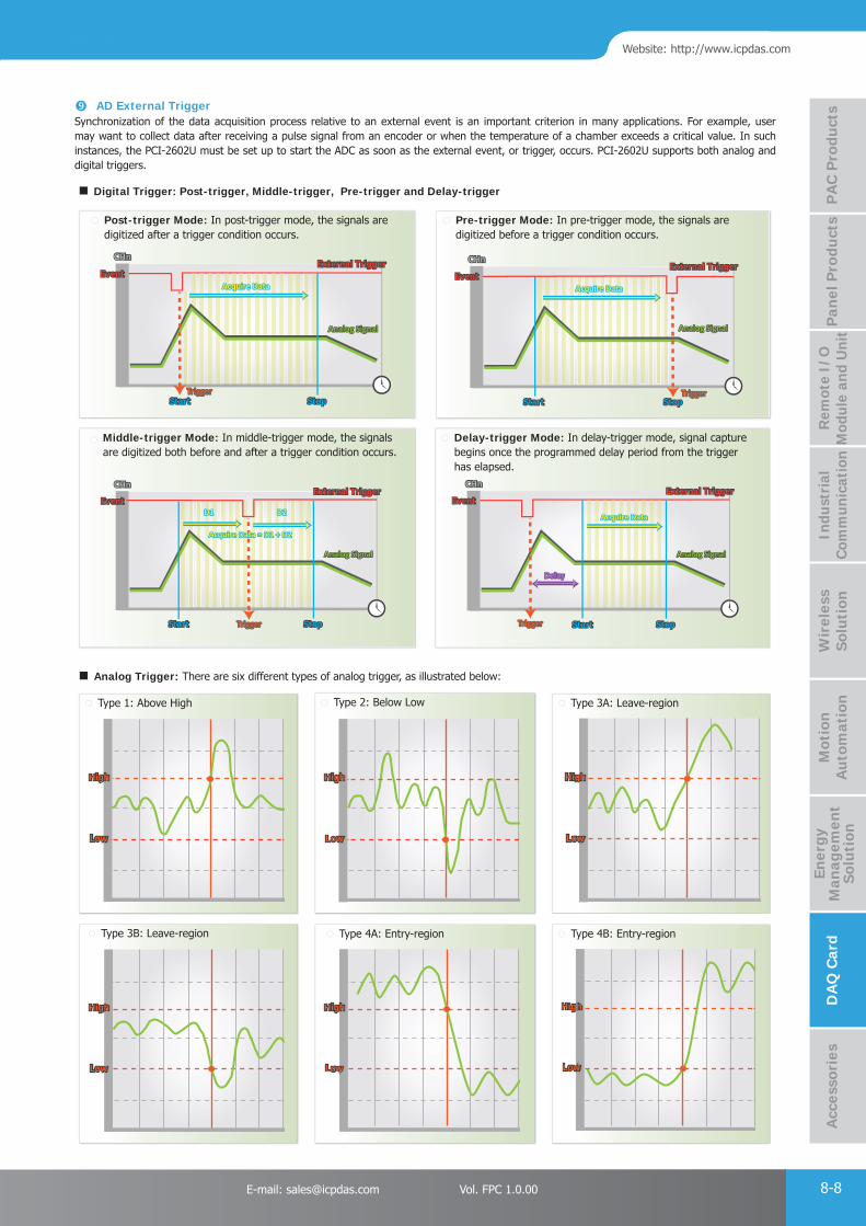
PAC Products
8-8E-mail: [email protected] Vol. FPC 1.0.00
Website: http://www.icpdas.com
PA
C P
rodu
cts
Pan
el P
rodu
cts
Rem
ote
I/O
M
odul
e an
d U
nit
DA
Q C
ard
Indu
stri
al
Com
mun
icat
ion
Wir
eles
s So
luti
onM
otio
n
Au
tom
atio
nA
cces
sori
esEn
ergy
M
anag
emen
tSo
luti
on
AD External TriggerSynchronization of the data acquisition process relative to an external event is an important criterion in many applications. For example, user may want to collect data after receiving a pulse signal from an encoder or when the temperature of a chamber exceeds a critical value. In such instances, the PCI-2602U must be set up to start the ADC as soon as the external event, or trigger, occurs. PCI-2602U supports both analog and digital triggers.
Digital Trigger: Post-trigger, Middle-trigger, Pre-trigger and Delay-trigger
Post-trigger Mode: In post-trigger mode, the signals are digitized after a trigger condition occurs.
Pre-trigger Mode: In pre-trigger mode, the signals are digitized before a trigger condition occurs.
CHnCHn
Analog SignalAnalog Signal
StartStart
EventEventExternal TriggerExternal Trigger
StopStopTriggerTrigger
Acquire DataAcquire Data
CHnCHn
Analog SignalAnalog Signal
StartStart
EventEventExternal TriggerExternal Trigger
StopStopTriggerTrigger
Acquire DataAcquire Data
Middle-trigger Mode: In middle-trigger mode, the signals are digitized both before and after a trigger condition occurs.
Delay-trigger Mode: In delay-trigger mode, signal capture begins once the programmed delay period from the trigger has elapsed.
CHnCHn
Analog SignalAnalog Signal
StartStart
EventEventExternal TriggerExternal Trigger
StopStopTriggerTrigger
Acquire Data = D1 + D2Acquire Data = D1 + D2
D2D2D1D1
CHnCHn
Analog SignalAnalog Signal
StartStart
EventEventExternal TriggerExternal Trigger
StopStopTriggerTrigger
Acquire DataAcquire Data
Analog Trigger: There are six different types of analog trigger, as illustrated below:
Type 1: Above High Type 2: Below Low Type 3A: Leave-region
HighHigh
LowLow
HighHigh
LowLow
HighHigh
LowLow
Type 3B: Leave-region Type 4A: Entry-region Type 4B: Entry-region
HighHigh
LowLow
HighHigh
LowLow
HighHigh
LowLow

PAC Products
8-9 ICP DAS CO., LTD. Professional Provider of High Quality Industrial Computer Products and Data Acquisition Systems Vol. FPC 1.0.00
PCI-2602U CRUniversal PCI, 1 MS/s High-Speed, 16-channel Analog Input, 2-channel Analog Output and 32-channel DI/O (RoHS)
PB7PB5
PB3
PB1
PA7
+5 V (Output)Ext_TRG
Trg_GATE
Pacer_OUT
D_GND
PD7PD5
PD3PD1PC7
PC5
PC3
PC1
D_GND D_GNDPB6PB4
PB2
PB0
+12 V (Output)Cnt0_GATE
Cnt0_OUT
Cnt0_CLK
D_GND
PD6PD4
PD2PD0PC6
PC4
PC2
PC0
1516
17
18
19
0102
03
04
05
0607
080910
11
12
13
14
Terminal No.
Female SCSI 68-pin (CON1)
AI3
AI1
PA5
PA3
PA1
AO_GND
AO1_OUTAO1_REF
AI_GNDAI15AI13
AI11
AI9
AI7
AI5
3334
20
21
22
23
2425
262728
29
30
31
32 AI4AI2AI0
PA6PA4
PA2
PA0
AO_GND
AO0_OUTAO0_REF
AI_GNDAI14AI12
AI10
AI8
AI6
35
36
37
4748
49
50
3839
4041
43
44
45
46
42
646566
67
68
5152
53
54
55
5657
585960
61
62
63
PinAssign-ment
PinAssign-ment
Pin Assignments
Hardware Specifi cations Software
Sample Programs
Driver
32/64-bit Windows XP/2003/2008/Vista/7/8
LabVIEW Toolkit
VB/VC/Delphi/BCB/VB.NET/C#.NET/VC.NET/MATLAB Demo
DN-68ADIN-Rail Mountable I/O Connector Block with 68-pin SCSI II Female Connector. (RoHS)
CA-SCSI15-H 68-pin SCSI-II Connector Cable, 1.5 m
Accessories
Ordering Information
DN-68A CA-SCSI15-H
Analog Input
Channels 16 Single-ended/8 Differential
AD Converter 16-bit, 1 μs conversion time
Sampling Rate 1 MS/s (Max.)
FIFO Size 8192 Samples
Bipolar Range ±10.24 V, ±5.12 V, ±2.56 V
Analog Output
Channels 2
Resolution 16-bit
FIFO Size 512 Samples
Output Rate 20 MS/s (Max.)
Output Range±10 V, ±5 V, ±EXT_REF,
0 ~ +10 V, 0 ~ +5 V, 0 ~ EXT_REF
Programmable Digital I/O
Channels 32 (4-port Programmable)
Digital Input
Compatibility 5 V/TTL
FIFO Size 512 Samples
Input Voltage Low: 0.8 V Max.; High: 2.0 V Min.
Digital Output
Compatibility 5 V/CMOS
DO FIFO Size 512 Samples
Output Voltage Logic 0: 0.4 V Max.; Logic 1: 2.4 V Min.
Output VoltageSink: 6 mA @ 0.33 V
Source: 6 mA @ 4.77 V
General
Bus Type 3.3 V/5 V Universal PCI, 32-bit, 33 MHz
Card ID Yes (4-bit)
Connectors Female SCSI II 68-pin x 1
Power Consumption 1 A @ +5 V (Max.)
Operating Temperature 0°C to +60°C
Humidity 5 to 85% RH, Non-condensing

PAC Products
8-10E-mail: [email protected] Vol. FPC 1.0.00
Website: http://www.icpdas.com
PA
C P
rodu
cts
Pan
el P
rodu
cts
Rem
ote
I/O
M
odul
e an
d U
nit
DA
Q C
ard
Indu
stri
al
Com
mun
icat
ion
Wir
eles
s So
luti
onM
otio
n
Au
tom
atio
nA
cces
sori
esEn
ergy
M
anag
emen
tSo
luti
on
Model Name PISO-DA2U PISO-DA4U PISO-DA8U PISO-DA16U PIO-DA4U PIO-DA8U PIO-DA16U
Interface Universal PCI
Analog Output
Channels 2 4 8 16 4 8 16
Resolution 12-bit 14-bit 14-bit 14-bit 14-bit 14-bit 14-bit
Isolation Voltage 3750 VDC 2500 VDC 2500 VDC 2500 VDC - - -
Isolation TypeBus Type,CH-to-CH
Bus Type Bus Type Bus Type - - -
Built-in DC/DC Converter
3000 VDC 3000 VDC 3000 VDC 3000 VDC - - -
Output Voltage
± 5 V± 10 V0 ~ 5 V0 ~10 V
± 10 V ± 10 V ± 10 V ± 10 V ± 10 V ± 10 V
Output Current0 ~ 20 mA4 ~ 20 mA
0 ~ 20 mA 0 ~ 20 mA 0 ~ 20 mA 0 ~ 20 mA 0 ~ 20 mA 0 ~ 20 mA
Output Driving ± 5 mA ± 5 mA ± 5 mA ± 5 mA ± 5 mA ± 5 mA ± 5 mA
Digital I/O
DI Channels - 16 16 16 16 16 16
DO Channels - 16 16 16 16 16 16
Compatibility - 5 V/TTL 5 V/TTL 5 V/TTL 5 V/TTL 5 V/TTL 5 V/TTL
Timer/Counter
Channels - 3 3 3 3 3 3
Resolution - 16-bit 16-bit 16-bit 16-bit 16-bit 16-bit
Clock Source - 4 MHz 4 MHz 4 MHz 4 MHz 4 MHz 4 MHz
2.3 Analog Output Boards
2.2 Memory Boards
Features On-board 512 KB SRAM
Two Li-batteries, BT1 & BT2, for dual battery-backup the data of the SRAM
LED indicators for Li-batteries states: normal, low voltage, fault
16-bit general purpose TTL-compatible D/O
12-bit general purpose TTL-compatible D/I (DI 4 ~ 15)
4-bit battery status read back (DI 0 ~ 3)
Universal PCI card, supports both 5 V and 3.3 V PCI bus
PCI-M512UUniversal PCI, 512 KB dual-battery backup SRAM board

PAC Products
8-11 ICP DAS CO., LTD. Professional Provider of High Quality Industrial Computer Products and Data Acquisition Systems Vol. FPC 1.0.00
Model Name PCI-D64HU
PIO-D24U
PIO-D48U
PIO-D48SU
PIO-D56U
PIO-D64U
PIO-D96U
PIO-D96SU
PIO-D144U
PIO-D144LU
PIO-D168U
PCI-TMC12A
Interface Universal PCI PCI Bus
Programmable DIO
Channels - 24 48 24 - 96 144 168 -
Digital Input
Channels 32 - - 16 32 - - - 16
Compatibility 5 V/TTL 5 V/CMOS 5 V/TTL 5 V/CMOS 5 V/TTL
Input Voltage
Logic 0 0.8 V Max.
Logic 1 2.0 V min.
Digital Output
Channels 32 - - 16 32 - - - 16
Compatibility 5 V/TTL 5 V/CMOS 5 V/TTL 5 V/CMOS 5 V/TTL
Output Voltage
Logic 00.55 V Max.
0.4 V Max.0.1 V Max.
0.4 V Max.
0.1 V Max.
0.4 V Max.
Logic 1 2.0 V min. 2.4 V Max. 4.4 V min.2.4 V Max.
4.4 V min. 2.4 V Max.
OutputCapability
Sink64 mA @ 0.55 V
64 mA @ 0.8 V
64 mA @ 0.8 V
CN1: 2.4 mA @
0.8 V 24 mA @ 0.8 V
64 mA @ 0.8 V
6 mA @ 0.33 V
64 mA @ 0.8 V
6 mA @ 0.33 V
64 mA @ 0.8 V
24 mA @ 0.8 VCN3:
64 mA @ 0.8 V
Source-32 mA @
2.0 V32 mA @
2.0 V32 mA @ 2.0 V
CN1: 0.8 mA @
2.0 V 15 mA @ 2.0 V
32 mA @ 2.0 V
6 mA @ 4.77 V
32 mA @ 2.0 V
6 mA @ 4.77 V
32 mA @ 2.0 V
15 mA @ 2.0 VCN3:
32 mA @ 2.0 V
Timer/Counter
Channels 3 - 2 - 6 - - - 12
Resolution 16-bit - 16-bit - 16-bit - - - 16-bit
Clock Source - - 4 MHz - 4 MHz - - - 8 MHz
Connector
SCSI II 100-pin - - - 1 - - - 1 - - - -
50-pin Header - - 1 - - - 3 - 5 5 6 -
40-pin Header 1 - - - - - - - - - - -
37-pin D-Sub 1 1 1 - 1 - 1 - 1 1 1 1
20-pin Header - - - - 2 5 - - - - - 2
NEW NEW NEW
2.4 Non-Isolated Digital I/O Boards
PIO-D96SUPIO-D96U
PIO D96SU PIO-D96SU PIO-D96U PIO-D96U
SCSI- Cabling
Classic Cabling
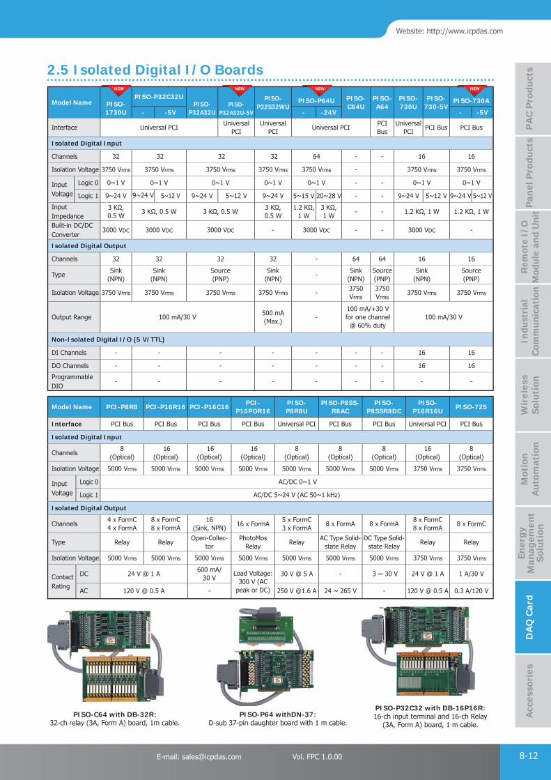
PAC Products
8-12E-mail: [email protected] Vol. FPC 1.0.00
Website: http://www.icpdas.com
PA
C P
rodu
cts
Pan
el P
rodu
cts
Rem
ote
I/O
M
odul
e an
d U
nit
DA
Q C
ard
Indu
stri
al
Com
mun
icat
ion
Wir
eles
s So
luti
onM
otio
n
Au
tom
atio
nA
cces
sori
esEn
ergy
M
anag
emen
tSo
luti
on
Model Name PISO-1730U
PISO-P32C32UPISO-
P32A32UPISO-
P32A32U-5V
PISO-P32S32WU
PISO-P64U PISO-C64U
PISO-A64
PISO-730U
PISO-730-5V
PISO-730A
- -5V - -24V - -5V
Interface Universal PCIUniversal
PCIUniversal
PCIUniversal PCI
PCI Bus
Universal PCI
PCI Bus PCI Bus
Isolated Digital Input
Channels 32 32 32 32 64 - - 16 16
Isolation Voltage 3750 Vrms 3750 Vrms 3750 Vrms 3750 Vrms 3750 Vrms - 3750 Vrms 3750 Vrms
Input Voltage
Logic 0 0~1 V 0~1 V 0~1 V 0~1 V 0~1 V - - 0~1 V 0~1 V
Logic 1 9~24 V 9~24 V 5~12 V 9~24 V 5~12 V 9~24 V 5~15 V 20~28 V - - 9~24 V 5~12 V 9~24 V 5~12 V
Input Impedance
3 KΩ, 0.5 W
3 KΩ, 0.5 W 3 KΩ, 0.5 W3 KΩ, 0.5 W
1.2 KΩ, 1 W
3 KΩ,1 W
- - 1.2 KΩ, 1 W 1.2 KΩ, 1 W
Built-in DC/DC Converter
3000 VDC 3000 VDC 3000 VDC - 3000 VDC - - 3000 VDC -
Isolated Digital Output
Channels 32 32 32 32 - 64 64 16 16
TypeSink
(NPN)Sink
(NPN)Source (PNP)
Sink (NPN)
-Sink
(NPN)Source (PNP)
Sink (NPN)
Source (PNP)
Isolation Voltage 3750 Vrms 3750 Vrms 3750 Vrms 3750 Vrms -3750 Vrms
3750 Vrms
3750 Vrms 3750 Vrms
Output Range 100 mA/30 V500 mA (Max.)
-100 mA/+30 V for one channel
@ 60% duty100 mA/30 V
Non-Isolated Digital I/O (5 V/TTL)
DI Channels - - - - - - - 16 16
DO Channels - - - - - - - 16 16
ProgrammableDIO
- - - - - - - - -
NEW NEW NEW NEW
2.5 Isolated Digital I/O Boards
Model Name PCI-P8R8 PCI-P16R16 PCI-P16C16PCI-
P16POR16PISO-P8R8U
PISO-P8SS-R8AC
PISO-P8SSR8DC
PISO-P16R16U
PISO-725
Interface PCI Bus PCI Bus PCI Bus PCI Bus Universal PCI PCI Bus PCI Bus Universal PCI PCI Bus
Isolated Digital Input
Channels8
(Optical) 16
(Optical) 16
(Optical) 16
(Optical)8
(Optical)8
(Optical)8
(Optical)16
(Optical)8
(Optical)
Isolation Voltage 5000 Vrms 5000 Vrms 5000 Vrms 5000 Vrms 5000 Vrms 5000 Vrms 5000 Vrms 3750 Vrms 3750 Vrms
Input Voltage
Logic 0 AC/DC 0~1 V
Logic 1 AC/DC 5~24 V (AC 50~1 kHz)
Isolated Digital Output
Channels4 x FormC4 x FormA
8 x FormC8 x FormA
16 (Sink, NPN)
16 x FormA5 x FormC3 x FormA
8 x FormA 8 x FormA8 x FormC8 x FormA
8 x FormC
Type Relay RelayOpen-Collec-
torPhotoMos
RelayRelay
AC Type Solid-state Relay
DC Type Solid-state Relay
Relay Relay
Isolation Voltage 5000 Vrms 5000 Vrms 5000 Vrms 5000 Vrms 5000 Vrms 5000 Vrms 5000 Vrms 3750 Vrms 3750 Vrms
Contact Rating
DC 24 V @ 1 A600 mA/
30 VLoad Voltage:
300 V (AC peak or DC)
30 V @ 5 A - 3 ~ 30 V 24 V @ 1 A 1 A/30 V
AC 120 V @ 0.5 A - 250 V @1.6 A 24 ~ 265 V - 120 V @ 0.5 A 0.3 A/120 V
PISO-C64 with DB-32R: 32-ch relay (3A, Form A) board, 1m cable.
PISO-P64 withDN-37: D-sub 37-pin daughter board with 1 m cable.
PISO-P32C32 with DB-16P16R: 16-ch input terminal and 16-ch Relay
(3A, Form A) board, 1 m cable.

PAC Products
8-13 ICP DAS CO., LTD. Professional Provider of High Quality Industrial Computer Products and Data Acquisition Systems Vol. FPC 1.0.00
Model NameISO-AD32
ISO-813ISA-DA
L H 8 16
Analog Input
Channels32 S.E./16 Diff.
32 S.E. -
Resolution 12-bit 12-bit -
Sampling Rate 200 kS/s. 10 kS/s. -
Isolation Voltage 500 Vrms 3000 Vrms -
FIFO Size 1 KB - -
Analog Output
Channels - - 8 16
Isolation Voltage - - 2500 VDC
Resolution - - 14-bit
Output Range - -±10 V
0~20 mA
Model Name ISO-P64 ISO-C64ISO-
P32C32ISO-
P32S32WISO-730 P8R8DIO P16R16DIO
Isolated Digital Input
Channels 64 - 32 32 16 8 16
Isolation Voltage
3750 Vrms - 3750 Vrms 3750 Vrms 3750 Vrms 5000 Vrms
Input Voltage 9 ~ 24 V - 9 ~ 24 V 5 ~ 24 V 9 ~ 24 V 5 ~ 24 V
Isolated Digital Output
Channels - 64 32 32 16 8 16
Isolation Voltage
- 3750 Vrms 3750 Vrms 3750 Vrms 3750 Vrms -
Compatibility - Sink Sink Sink Sink -
Relay Type - - - - -4 SPDT;4 SPST
8 SPDT;8 SPST
Non-Isolated DIO
DI Channels - - - - 16 - -
DO Channels - - - - 16 - -
Compatibility - - - - 5 V/TTL - -
Model Name A-826PG A-823PGL/A-823PGH A-822PGL/A-822PGH A-821PGL/A-821PGH A-812PG A-8111
Analog Input
Channels 16 S.E./ 8 Diff. 16 S.E./ 8 Diff. 16 S.E./ 8 Diff. 16 S.E./ 8 Diff. 16 S.E. 8 S.E.
Resolution 16-bit 12-bit 12-bit 12-bit 12-bit 12-bit
Sampling Rate 100 kS/s. 125 kS/s. 125 kS/s. 45 kS/s. 62.5 kS/s. 35 kS/s.
Analog Output
Channels 2 2 2 1 2 1
Resolution 12-bit 12-bit 12 12-bit 12-bit 12-bit
5V/TTL DIO
DI Channels 16 16 16 16 16 16
DI Channels 16 16 16 16 16 16
Timer/Counter
Channels 3 3 3 3 3 3
Model NameA-726 A-626 A-628 DIO-24 DIO-48 DIO-64/3 DIO-64/6 DIO-96 DIO-144 TMC-10
Interface ISA Bus
Analog Output
Channels 6 6 8 - - - - - -
Resolution 12-bit 12-bit 12-bit - - - - - -
5V/TTL DIO
DI Channels 16 16 16 - - 32 - - 8
DO Channels 16 16 16 - - 32 - - 8
Programmable DIO - - - 24 48 - 96 144 -
Timer/Counter
Channels - - - - 3 3 6 - - 10
NEW
ISA Bus, Isolated Data Acquisition Boards
ISA Bus, Multi-Function Boards
ISA Bus, Non-Isolated Data Acquisition Boards
3. ISA Bus Data Acquisition Boards
Signal Conditioning Modules (SG-3000 Series) P 9-11
Relay Modules P 9-44
Surge Protection Module (SG-770) P 9-22
Enclosures and Mounting Kit P 9-55
EMI Ferrite Split/Snap-On Core P 9-33
MISC P 9-66
AccessoriesAccessoriesAccessories 9
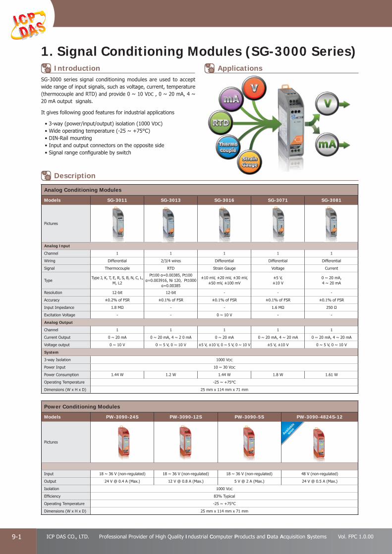
PAC Products
9-1 ICP DAS CO., LTD. Professional Provider of High Quality Industrial Computer Products and Data Acquisition Systems Vol. FPC 1.0.00
1. Signal Conditioning Modules (SG-3000 Series)
Analog Conditioning Modules
Models SG-3011 SG-3013 SG-3016 SG-3071 SG-3081
Pictures
Analog Input
Channel 1 1 1 1 1
Wiring Differential 2/3/4 wires Differential Differential Differential
Signal Thermocouple RTD Strain Gauge Voltage Current
TypeType J, K, T, E, R, S, B, N, C, L,
M, L2
Pt100 α=0.00385, Pt100 α=0.003916, Ni 120, Pt1000
α=0.00385
±10 mV, ±20 mV, ±30 mV,±50 mV, ±100 mV
±5 V, ±10 V
0 ~ 20 mA, 4 ~ 20 mA
Resolution 12-bit 12-bit - - -
Accuracy ±0.2% of FSR ±0.1% of FSR ±0.1% of FSR ±0.1% of FSR ±0.1% of FSR
Input Impedance 1.8 MΩ - - 1.6 MΩ 250 Ω
Excitation Voltage - - 0 ~ 10 V - -
Analog Output
Channel 1 1 1 1 1
Current Output 0 ~ 20 mA 0 ~ 20 mA, 4 ~ 2 0 mA 0 ~ 20 mA 0 ~ 20 mA, 4 ~ 20 mA 0 ~ 20 mA, 4 ~ 20 mA
Voltage output 0 ~ 10 V 0 ~ 5 V, 0 ~ 10 V ±5 V, ±10 V, 0 ~ 5 V, 0 ~ 10 V ±5 V, ±10 V 0 ~ 5 V, 0 ~ 10 V
System
3-way Isolation 1000 VDC
Power Input 10 ~ 30 VDC
Power Consumption 1.44 W 1.2 W 1.44 W 1.8 W 1.61 W
Operating Temperature -25 ~ +75°C
Dimensions (W x H x D) 25 mm x 114 mm x 71 mm
SG-3000 series signal conditioning modules are used to accept wide range of input signals, such as voltage, current, temperature (thermocouple and RTD) and provide 0 ~ 10 VDC , 0 ~ 20 mA, 4 ~ 20 mA output signals.
It gives following good features for industrial applications
• 3-way (power/input/output) isolation (1000 VDC)• Wide operating temperature (-25 ~ +75°C)• DIN-Rail mounting• Input and output connectors on the opposite side• Signal range confi gurable by switch
Introduction
Description
Applications
Availa
ble
soon
Power Conditioning Modules
Models PW-3090-24S PW-3090-12S PW-3090-5S PW-3090-4824S-12
Pictures
Input 18 ~ 36 V (non-regulated) 18 ~ 36 V (non-regulated) 18 ~ 36 V (non-regulated) 48 V (non-regulated)
Output 24 V @ 0.4 A (Max.) 12 V @ 0.8 A (Max.) 5 V @ 2 A (Max.) 24 V @ 0.5 A (Max.)
Isolation 1000 VDC
Effi ciency 83% Typical
Operating Temperature -25 ~ +75°C
Dimensions (W x H x D) 25 mm x 114 mm x 71 mm

PAC Products
9-2E-mail: [email protected] Vol. FPC 1.0.00
Website: http://www.icpdas.com
PA
C P
rodu
cts
Pan
el P
rodu
cts
Rem
ote
I/O
M
odul
e an
d U
nit
DA
Q C
ard
Indu
stri
al
Com
mun
icat
ion
Wir
eles
s So
luti
onM
otio
n
Au
tom
atio
nA
cces
sori
esEn
ergy
M
anag
emen
tSo
luti
on
SG-770
2. Surge Protection Module (SG-770)
SG-770 offers 7 differential or 14 single-ended for surge protection. SG-770 is approved with IEC 61000-4-5 and IEC 61000-4-12 standards. Each of channels supports 0 ~ ±30 VDC signal and each of channels is protected for surge achieves 6 kV.
Models SG-770
General
Input Channels 7 differential or 14 single-ended
Input Signal Type Voltage, Current, Thermocouple, RTD, RS-485/RS-422/RS-232, CAN
Max. Line Voltage 30 VDC
Surge Protection Performance
StandardIEC 61000-4-5IEC 61000-4-12
Max. Surge Voltage Line to Earth: ±6000 VDC Max.
Environment
Operating Temperature -25 ~ +75°C
Storage Temperature -30 ~ +75°C
Humidity 5 ~ 95% RH, Non-condensing
Dimensions (W x H x D) 123 mm x 72 mm x 33 mm
SG-770 CR 7 channel differential or 14 channel single-ended surge protector (RoHS)
Features IEC 61000-4-5, IEC 61000-4-12
6 kV Surge Protection
RoHS Compliance
A Wide Range of Operating Temperature: -25 ~ +75°C
Easy Wiring
Introduction
Ordering Information
Specifi cations
Applications Pin Assignments
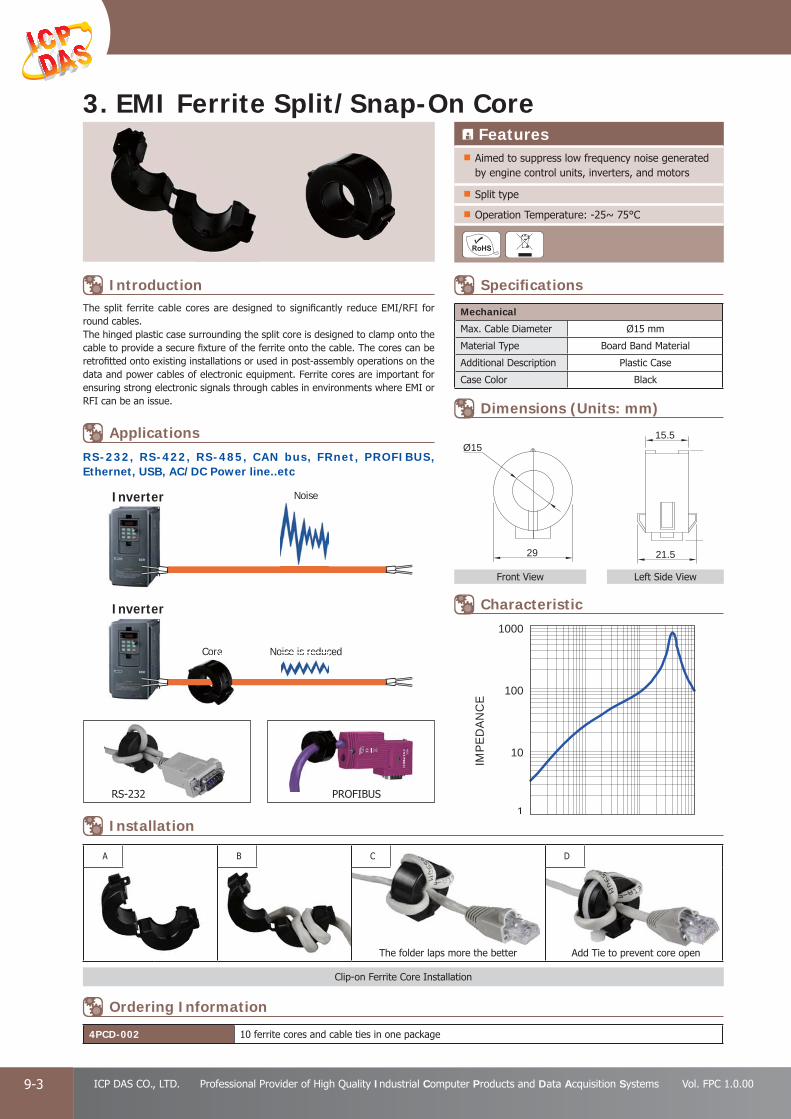
PAC Products
9-3 ICP DAS CO., LTD. Professional Provider of High Quality Industrial Computer Products and Data Acquisition Systems Vol. FPC 1.0.00
3. EMI Ferrite Split/Snap-On Core
Mechanical
Max. Cable Diameter Ø15 mm
Material Type Board Band Material
Additional Description Plastic Case
Case Color Black
4PCD-002 10 ferrite cores and cable ties in one package
Left Side ViewFront View
Features Aimed to suppress low frequency noise generated by engine control units, inverters, and motors
Split type
Operation Temperature: -25~ 75°C
The split ferrite cable cores are designed to signifi cantly reduce EMI/RFI for round cables.The hinged plastic case surrounding the split core is designed to clamp onto the cable to provide a secure fi xture of the ferrite onto the cable. The cores can be retrofi tted onto existing installations or used in post-assembly operations on the data and power cables of electronic equipment. Ferrite cores are important for ensuring strong electronic signals through cables in environments where EMI or RFI can be an issue.
Clip-on Ferrite Core Installation
A B C D
The folder laps more the better Add Tie to prevent core open
IMPE
DAN
CE
1
10
100
1000
29
Ø15
21.5
15.5
M
RS-232 PROFIBUS
Inverter
Noise is reducedCore
Inverter
Core
NoiseNoise
oise is reduc
RS-232, RS-422, RS-485, CAN bus, FRnet, PROFIBUS, Ethernet, USB, AC/DC Power line..etc
Ordering Information
Installation
Applications
Introduction Specifi cations
Dimensions (Units: mm)
Characteristic

PAC Products
9-4E-mail: [email protected] Vol. FPC 1.0.00
Website: http://www.icpdas.com
PA
C P
rodu
cts
Pan
el P
rodu
cts
Rem
ote
I/O
M
odul
e an
d U
nit
DA
Q C
ard
Indu
stri
al
Com
mun
icat
ion
Wir
eles
s So
luti
onM
otio
n
Au
tom
atio
nA
cces
sori
esEn
ergy
M
anag
emen
tSo
luti
on
Models RM-20.22 RM-22.22 RM-38.61 RM-48.61 RM-48.62
Pictures
Relay Finder 20.22.9.024.4000 Finder 22.22.9.024.4000 Finder 34.51.7.024.0010 FINDER - 40.61.7.024.0000 FINDER - 44.62.7.024.0000
Type Step Relay Power Relay
Channel 1
Contact Form A (DPST) Form A (DPST) Form C (SPDT) Form C (SPDT) Form C (SPDT)
Operating Voltage Range 230 VAC 230 VAC 250 VAC 250 VAC 250 VAC
Max. Load Current 16 A 20 A 6 A 16 A 10 A
Operate Time 15 ms 15 ms 5 ms 7 ms 7 ms
Release Time 8 ms 8 ms 3 ms 3 ms 3 ms
LED Indicator -
Mechanical
Dimensions (W x L x D) 17.5 mm x 84 mm x 62.7 mm 76.5 mm x 6.5 mm x 89 mm 75 mm x 15.5 mm x 78.5 mm
Installation DIN-Rail Mounting
Note1: RM-38.61: 5 pcs in one package RM-48.61: 4 pcs in one package RM-48.62: 4 pcs in one packageNote2: RM-38-093.20 is a 20-way jumper link for RM-38.61
Models DN-SSR4 DN-SSR4DC
Pictures
Relay A5P-204U D3P-054
Type Solid-State Relay
Channel 4 channels
Contact Form A (SPST)
Operating Voltage Range 250 VAC / 30 VDC 50 VDC
Max. Load Current 4 A
Operate Time 1/2 Cycle + 1 ms and below 0.5 ms and below (Resistance load)
Release Time 1/2 Cycle + 1 ms and below 0.5 ms and below (Resistance load)
LED Indicator Yes (for Relay status)
Mechanical
Dimensions (W x L x D) 101 mm x 77 mm x 66 mm
Installation DIN-Rail Mounting
Models DN-PR4 RM-104, RM-108, RM-116 RM-204, RM-208, RM-216
Pictures
Relay VE-24H5-K FINDER - 40.61.7.024.0000 FINDER - 44.52.7.024.0000
Type Power Relay
Channel 4RM-104: 4 channelsRM-108: 8 channelsRM-116: 16 channels
RM-204: 4 channelsRM-208: 8 channelsRM-216: 16 channels
Contact Form C Form C (SPDT) Form C (DPDT)
Operating Voltage Range 250 VAC / 30 VDC 250 VAC 250 VAC
Max. Load Current 5 A 16 A 6 A
Operate Time 10 ms (Typical) 7 ms (Typical) 8 ms (Typical)
Release Time 5 ms (Typical) 3 ms (Typical) 5 ms (Typical)
LED Indicator Yes (for Relay status)
Mechanical
Dimensions (W x L x D) 96 mm x 103 mm x 34 mm RM-104: 79 mm x 87 mm x 63 mmRM-108: 135 mm x 87 mm x 63 mmRM-116: 270 mm x 87 mm x 63 mm
RM-204: 90 mm x 87 mm x 63 mmRM-208: 169 mm x 87 mm x 63 mmRM-216: 327 mm x 87 mm x 63 mm
Installation DIN-Rail Mounting
4. Relay Modules

PAC Products
9-5 ICP DAS CO., LTD. Professional Provider of High Quality Industrial Computer Products and Data Acquisition Systems Vol. FPC 1.0.00
5. Enclosures and Mounting Kit
I-3625-ENC CR Industrial Enclosure (RoHS)
RK-3UD-R 19" Rack Mounting Kit, 3U
Includes
Case Accessory
2 x Polyamide cable glands
6 x captive lid screws
1 x DIN-Rail (35.8 cm)
Mechanical
Casing Plastic
Dimensions (W x H x D) 360 mm x 254 mm x 165 mm
Environmental
Temperature 0 ~ +50°C for Protection rating IP66
Mechanical
Dimensions (W x H x D) 481 mm x 132 mm x 125 mm
I-950-ENC CR Industrial Enclosure (254 mm x 180 mm x 90 mm) (RoHS)
I-951-ENC CR Industrial Enclosure (254 mm x 180 mm x 111 mm) (RoHS)
Models I-950-ENC I-951-ENC
Includes
Case Accessory
2 x Polyamide cable glands
4 x captive lid screws
1 x DIN-Rail (20 cm)
Mechanical
Casing Plastic
Dimensions (W x H x D) 254 mm x 180 mm x 90 mm 254 mm x 180 mm x 111 mm
Environmental
Temperature 0 ~ +50°C for Protection rating IP66
RK-3UD-R
I-3625-ENC
I-950-ENC/I-951-ENC
I-950-ENC
I-951-ENC
I-950-ENC
I-951-ENC
19" Rack Mounting Kit, 3U
Specifi cations
Specifi cations
Specifi cations
Ordering Information
Ordering Information
Ordering Information
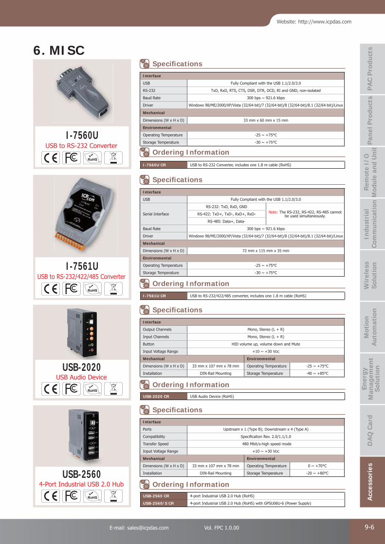
PAC Products
9-6E-mail: [email protected] Vol. FPC 1.0.00
Website: http://www.icpdas.com
PA
C P
rodu
cts
Pan
el P
rodu
cts
Rem
ote
I/O
M
odul
e an
d U
nit
DA
Q C
ard
Indu
stri
al
Com
mun
icat
ion
Wir
eles
s So
luti
onM
otio
n
Au
tom
atio
nA
cces
sori
esEn
ergy
M
anag
emen
tSo
luti
on
Interface
USB Fully Compliant with the USB 1.1/2.0/3.0
RS-232 TxD, RxD, RTS, CTS, DSR, DTR, DCD, RI and GND; non-isolated
Baud Rate 300 bps ~ 921.6 kbps
Driver Windows 98/ME/2000/XP/Vista (32/64-bit)/7 (32/64-bit)/8 (32/64-bit)/8.1 (32/64-bit)/Linux
Mechanical
Dimensions (W x H x D) 33 mm x 60 mm x 15 mm
Environmental
Operating Temperature -25 ~ +75°C
Storage Temperature -30 ~ +75°C
Interface
USB Fully Compliant with the USB 1.1/2.0/3.0
Serial Interface
RS-232: TxD, RxD, GNDNote: The RS-232, RS-422, RS-485 cannot
be used simultaneously.RS-422: TxD+, TxD-, RxD+, RxD-
RS-485: Data+, Data-
Baud Rate 300 bps ~ 921.6 kbps
Driver Windows 98/ME/2000/XP/Vista (32/64-bit)/7 (32/64-bit)/8 (32/64-bit)/8.1 (32/64-bit)/Linux
Mechanical
Dimensions (W x H x D) 72 mm x 115 mm x 35 mm
Environmental
Operating Temperature -25 ~ +75°C
Storage Temperature -30 ~ +75°C
USB-2020 CR USB Audio Device (RoHS)
I-7560U CR USB to RS-232 Converter, includes one 1.8 m cable (RoHS)
I-7561U CR USB to RS-232/422/485 converter, includes one 1.8 m cable (RoHS)
USB-2560 CR 4-port Industrial USB 2.0 Hub (RoHS)
USB-2560/S CR 4-port Industrial USB 2.0 Hub (RoHS) with GPSU06U-6 (Power Supply)
I-7560U
I-7561U
Interface
Output Channels Mono, Stereo (L + R)
Input Channels Mono, Stereo (L + R)
Button HID volume up, volume down and Mute
Input Voltage Range +10 ~ +30 VDC
Mechanical Environmental
Dimensions (W x H x D) 33 mm x 107 mm x 78 mm Operating Temperature -25 ~ +75°C
Installation DIN-Rail Mounting Storage Temperature -40 ~ +85°C
Interface
Ports Upstream x 1 (Type B); Downstream x 4 (Type A)
Compatibility Specifi cation Rev. 2.0/1.1/1.0
Transfer Speed 480 Mbit/s-high speed mode
Input Voltage Range +10 ~ +30 VDC
Mechanical Environmental
Dimensions (W x H x D) 33 mm x 107 mm x 78 mm Operating Temperature 0 ~ +70°C
Installation DIN-Rail Mounting Storage Temperature -20 ~ +80°C
USB to RS-232 Converter
USB to RS-232/422/485 Converter
USB-2020
USB-2560
USB Audio Device
4-Port Industrial USB 2.0 Hub
6. MISCSpecifi cations
Specifi cations
Specifi cations
Specifi cations
Ordering Information
Ordering Information
Ordering Information
Ordering Information


