Int. Journal of Electrical & Electronics NITTTR, Chandigarh Investigati Me Rajni Gu Associate Professor, Department of ECE M.T Dep SBSSTC, (PTU, Kapurthala) SBS [email protected], gurs am Abstract - In this work, a Split Ring R cell is simulated in a waveguide with e solver High Frequency Structure Analytical calculations of the inductan have been also carried out to obtain the for SRR dimensions. A comparison betw simulated resonance frequencies)) is done between simulated and measured reson achieved. Index Terms – Split Ring Resonator (S Unit cell, resonant frequency. I. INTRODUCTION Antennas are gaining attentio role in today’s world of wireless comm There are a lot of techniques have been to to enhance the antenna performance Metamaterials (structure based materia ground, patch or substrate is one of t 1967, Veselago through his theore proved the existence of metamaterial are engineered materials that have properties that are not found in nature. exhibits negative permeability (μ permittivity (ε) and are defined as materials (DNG). In case of single neg the only permeability (μ) negative mat mu negative (MNG) and only permi materials are epsilon negative Metamaterial structure is comprised of elements that generates negative perme permittivity respectively. The concept o reversed the Snell's law, Doppler radiation because of its unconventional In 1981 the first ‘split ring resonator Hardy [6]. In 1999 the periodic array magnetic rings known as SRR was negative permeability and proved b nowadays has become the pop component. There are many structures o SRR are available, such as double spl broadside couple SRR (BC-SRR), spira edge coupled SRR (EC-SRR). SRR i important artificial atom for the artific and fabrication. However, there are sti of SRR that have scope of an impr behind this work is to investigate the p models of SRR obtained by varyi dimension. In this work, a double spli been considered as a unit cell and inve Engg. Vol. 2, Spl. Issue 1 (2015) e-ISSN: 16 EDIT -2015 ion on Frequency Analy etamaterial Structure ursharan Kaur, Amanpreet Kaur Dr. An Tech. Research Scholar, Associat partment of ECE Departm SSTC, (PTU, Kapurthala) SLIET ( [email protected], marwaha_anup [email protected]Resonator (SRR) unit electromagnetic field Simulator (HFSS). nce and capacitance resonant frequencies ween calculated and e. A good correlation nance frequencies is SRR), Metamaterial, on due to their vital munication systems. used by researchers e parameters. Use of als) in antennas on these techniques. In etical investigation [1]. Metamaterials unnatural physical These metamaterial μ) and negative as double negative gative metamaterial, terials are known as ittivity (ε) negative (ENG) materials. f SRR and thin wire eability and negative of metamaterial has Effect, Cheronkov properties [2-5]. r’ was invented by of conducting non- first used to attain by Pendry [7] and pular metamaterial of different types of lit SRR (DS-SRR), al SRR (S-SRR) and is considered as an cial media’s design ill some parameters rovement. The idea performance of nine ing its parameters it ring structure has estigation is done on SRR instead of an array performance calculation. Di and comparison for calculat has been carried out for d HFSS software is used to a SRR models. II. SRR UNIT The SRR cell cons cuts (splits) at the opposite e between them and are made magnetic flux will generate rings, in response to which ri intensify the incident field. leads to resonant wavelengths the rings. Figure1 illustrates (SRR), a highly conductive adjusted by the capacitance b Figure 5. Geometry of a Split R The SRR is placed above th 5880 of thickness of 3.175 m of 2.2 and loss tangent is 0.0 in a waveguide. Perfect elec assigned to both faces of t conductor boundary conditio bottom of the Z-axis. The waveports. Wave penetrates ports assigned on Y-axis. [8] of SRR inside waveguide. 694-2310 | p-ISSN: 1694-2426 166 ysis of nupma Marwaha te Professor ment of ECE (Deemed University), Longowa [email protected]y to simplify analysis and imensions of SRR are varied ted and resonating frequency different models. The Ansoft analyse various parameters of T CELL DESIGN sists of concentric rings with ends. Rings have small spacing e of copper like metals. The e the rotating currents in the ings produce their own flux to Presence of splits in the ring s greater than the diameters of s a dual split ring resonator e structure having inductance between the two rings. Ring Resonator with dimensions. he Rogers RT/duroid substrate mm, relative permittivity ( ) 0009. The unit cell is enclosed ctric conductor boundaries are the X axis. Perfect magnetic ons are assigned at top and unit cell is excited by the s through the two waveguide ]. Figure 2 presents a structure
Abstract - In this work, a Split Ring Resonator (SRR) unitcell is simulated in a waveguide with electromagnetic fieldsolver High Frequency Structure Simulator (HFSS).Analytical calculations of the inductance and capacitancehave been also carried out to obtain the resonant frequenciesfor SRR dimensions. A comparison between calculated andsimulated resonance frequencies)) is done. A good correlationbetween simulated and measured resonance frequencies isachieved.
Index Terms – Split Ring Resonator (SRR), Metamaterial,Unit cell, resonant frequency.
I. INTRODUCTION
Antennas are gaining attention due to their vitalrole in today’s world of wireless communication systems.There are a lot of techniques have been used by researchersto to enhance the antenna performance parameters. Use ofMetamaterials (structure based materials) in antennas onground, patch or substrate is one of these techniques. In1967, Veselago through his theoretical investigationproved the existence of metamaterial [1]. Metamaterialsare engineered materials that have unnatural physicalproperties that are not found in nature. These metamaterialexhibits negative permeability (μ) and negativepermittivity (ε) and are defined as double negativematerials (DNG). In case of single negative metamaterial,the only permeability (μ) negative materials are known asmu negative (MNG) and only permittivity (ε) negativematerials are epsilon negative (ENG) materials.Metamaterial structure is comprised of SRR and thin wireelements that generates negative permeability and negativepermittivity respectively. The concept of metamaterial hasreversed the Snell's law, Doppler Effect, Cheronkovradiation because of its unconventional properties [2-5].In 1981 the first ‘split ring resonator’ was invented byHardy [6]. In 1999 the periodic array of conducting non-magnetic rings known as SRR was first used to attainnegative permeability and proved by Pendry [7] andnowadays has become the popular metamaterialcomponent. There are many structures of different types ofSRR are available, such as double split SRR (DS-SRR),broadside couple SRR (BC-SRR), spiral SRR (S-SRR) andedge coupled SRR (EC-SRR). SRR is considered as animportant artificial atom for the artificial media’s designand fabrication. However, there are still some parametersof SRR that have scope of an improvement. The ideabehind this work is to investigate the performance of ninemodels of SRR obtained by varying its parametersdimension. In this work, a double split ring structure hasbeen considered as a unit cell and investigation is done on
SRR instead of an array to simplify analysis andperformance calculation. Dimensions of SRR are variedand comparison for calculated and resonating frequencyhas been carried out for different models. The AnsoftHFSS software is used to analyse various parameters ofSRR models.
II. SRR UNIT CELL DESIGN
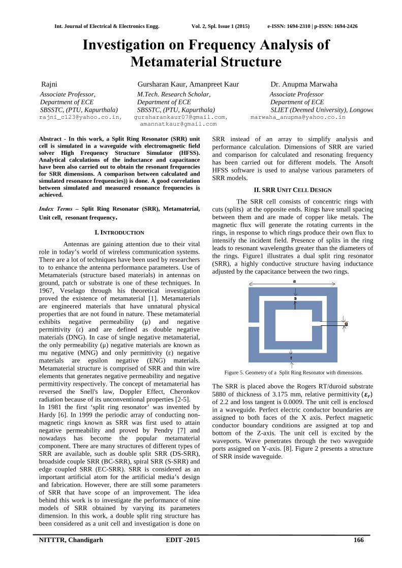
The SRR cell consists of concentric rings withcuts (splits) at the opposite ends. Rings have small spacingbetween them and are made of copper like metals. Themagnetic flux will generate the rotating currents in therings, in response to which rings produce their own flux tointensify the incident field. Presence of splits in the ringleads to resonant wavelengths greater than the diameters ofthe rings. Figure1 illustrates a dual split ring resonator(SRR), a highly conductive structure having inductanceadjusted by the capacitance between the two rings.
Figure 5. Geometry of a Split Ring Resonator with dimensions.
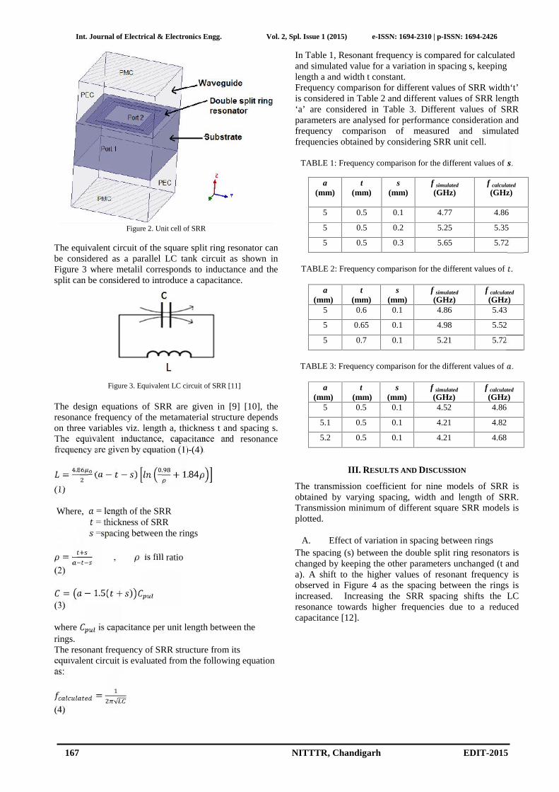
The SRR is placed above the Rogers RT/duroid substrate5880 of thickness of 3.175 mm, relative permittivity ( )of 2.2 and loss tangent is 0.0009. The unit cell is enclosedin a waveguide. Perfect electric conductor boundaries areassigned to both faces of the X axis. Perfect magneticconductor boundary conditions are assigned at top andbottom of the Z-axis. The unit cell is excited by thewaveports. Wave penetrates through the two waveguideports assigned on Y-axis. [8]. Figure 2 presents a structureof SRR inside waveguide.
Abstract - In this work, a Split Ring Resonator (SRR) unitcell is simulated in a waveguide with electromagnetic fieldsolver High Frequency Structure Simulator (HFSS).Analytical calculations of the inductance and capacitancehave been also carried out to obtain the resonant frequenciesfor SRR dimensions. A comparison between calculated andsimulated resonance frequencies)) is done. A good correlationbetween simulated and measured resonance frequencies isachieved.
Index Terms – Split Ring Resonator (SRR), Metamaterial,Unit cell, resonant frequency.
I. INTRODUCTION
Antennas are gaining attention due to their vitalrole in today’s world of wireless communication systems.There are a lot of techniques have been used by researchersto to enhance the antenna performance parameters. Use ofMetamaterials (structure based materials) in antennas onground, patch or substrate is one of these techniques. In1967, Veselago through his theoretical investigationproved the existence of metamaterial [1]. Metamaterialsare engineered materials that have unnatural physicalproperties that are not found in nature. These metamaterialexhibits negative permeability (μ) and negativepermittivity (ε) and are defined as double negativematerials (DNG). In case of single negative metamaterial,the only permeability (μ) negative materials are known asmu negative (MNG) and only permittivity (ε) negativematerials are epsilon negative (ENG) materials.Metamaterial structure is comprised of SRR and thin wireelements that generates negative permeability and negativepermittivity respectively. The concept of metamaterial hasreversed the Snell's law, Doppler Effect, Cheronkovradiation because of its unconventional properties [2-5].In 1981 the first ‘split ring resonator’ was invented byHardy [6]. In 1999 the periodic array of conducting non-magnetic rings known as SRR was first used to attainnegative permeability and proved by Pendry [7] andnowadays has become the popular metamaterialcomponent. There are many structures of different types ofSRR are available, such as double split SRR (DS-SRR),broadside couple SRR (BC-SRR), spiral SRR (S-SRR) andedge coupled SRR (EC-SRR). SRR is considered as animportant artificial atom for the artificial media’s designand fabrication. However, there are still some parametersof SRR that have scope of an improvement. The ideabehind this work is to investigate the performance of ninemodels of SRR obtained by varying its parametersdimension. In this work, a double split ring structure hasbeen considered as a unit cell and investigation is done on
SRR instead of an array to simplify analysis andperformance calculation. Dimensions of SRR are variedand comparison for calculated and resonating frequencyhas been carried out for different models. The AnsoftHFSS software is used to analyse various parameters ofSRR models.
II. SRR UNIT CELL DESIGN
The SRR cell consists of concentric rings withcuts (splits) at the opposite ends. Rings have small spacingbetween them and are made of copper like metals. Themagnetic flux will generate the rotating currents in therings, in response to which rings produce their own flux tointensify the incident field. Presence of splits in the ringleads to resonant wavelengths greater than the diameters ofthe rings. Figure1 illustrates a dual split ring resonator(SRR), a highly conductive structure having inductanceadjusted by the capacitance between the two rings.
Figure 5. Geometry of a Split Ring Resonator with dimensions.
The SRR is placed above the Rogers RT/duroid substrate5880 of thickness of 3.175 mm, relative permittivity ( )of 2.2 and loss tangent is 0.0009. The unit cell is enclosedin a waveguide. Perfect electric conductor boundaries areassigned to both faces of the X axis. Perfect magneticconductor boundary conditions are assigned at top andbottom of the Z-axis. The unit cell is excited by thewaveports. Wave penetrates through the two waveguideports assigned on Y-axis. [8]. Figure 2 presents a structureof SRR inside waveguide.
The equivalent circuit of the square split ring resonator canbe considered as a parallel LC tank circuit as shown inFigure 3 where metalil corresponds to inductance and thesplit can be considered to introduce a capacitance.
Figure 3. Equivalent LC circuit of SRR [11]
The design equations of SRR are given in [9] [10], theresonance frequency of the metamaterial structure dependson three variables viz. length a, thickness t and spacing s.The equivalent inductance, capacitance and resonancefrequency are given by equation (1)-(4).= . ( − − ) . + 1.84(1)
Where, = length of the SRR= thickness of SRR=spacing between the rings= , is fill ratio
(2)= − 1.5( + )(3)
where is capacitance per unit length between therings.The resonant frequency of SRR structure from itsequivalent circuit is evaluated from the following equationas: = √(4)
In Table 1, Resonant frequency is compared for calculatedand simulated value for a variation in spacing s, keepinglength a and width t constant.Frequency comparison for different values of SRR width‘t’is considered in Table 2 and different values of SRR length‘a’ are considered in Table 3. Different values of SRRparameters are analysed for performance consideration andfrequency comparison of measured and simulatedfrequencies obtained by considering SRR unit cell.
TABLE 1: Frequency comparison for the different values of .
a(mm)
t(mm)
s(mm)
f simulated
(GHz)f calculated
(GHz)
5 0.5 0.1 4.77 4.86
5 0.5 0.2 5.25 5.35
5 0.5 0.3 5.65 5.72
TABLE 2: Frequency comparison for the different values of .
a(mm)
t(mm)
s(mm)
f simulated
(GHz)f calculated
(GHz)5 0.6 0.1 4.86 5.43
5 0.65 0.1 4.98 5.52
5 0.7 0.1 5.21 5.72
TABLE 3: Frequency comparison for the different values of .
a(mm)
t(mm)
s(mm)
f simulated
(GHz)f calculated
(GHz)5 0.5 0.1 4.52 4.86
5.1 0.5 0.1 4.21 4.82
5.2 0.5 0.1 4.21 4.68
III. RESULTS AND DISCUSSION
The transmission coefficient for nine models of SRR isobtained by varying spacing, width and length of SRR.Transmission minimum of different square SRR models isplotted.
A. Effect of variation in spacing between ringsThe spacing (s) between the double split ring resonators ischanged by keeping the other parameters unchanged (t anda). A shift to the higher values of resonant frequency isobserved in Figure 4 as the spacing between the rings isincreased. Increasing the SRR spacing shifts the LCresonance towards higher frequencies due to a reducedcapacitance [12].
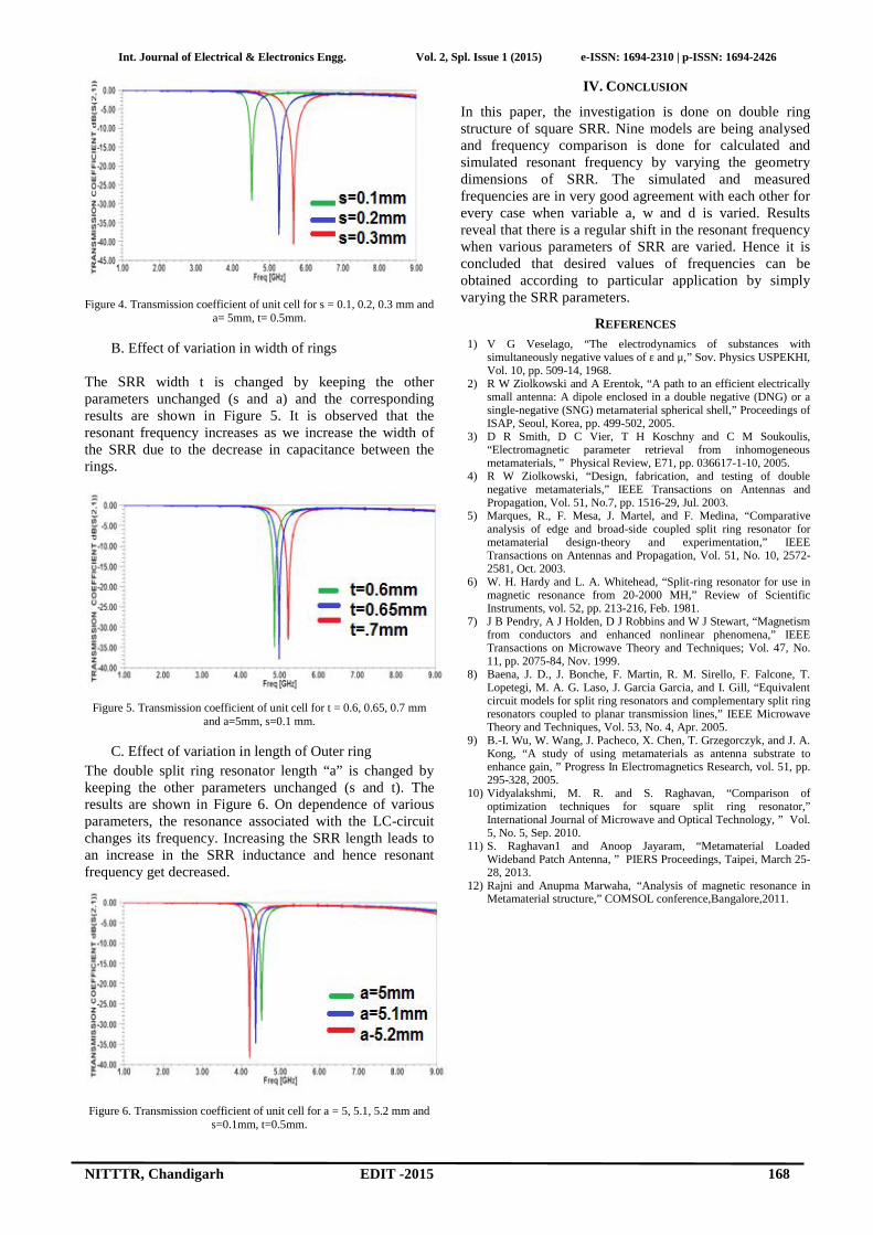
Figure 4. Transmission coefficient of unit cell for s = 0.1, 0.2, 0.3 mm anda= 5mm, t= 0.5mm.
B. Effect of variation in width of rings
The SRR width t is changed by keeping the otherparameters unchanged (s and a) and the correspondingresults are shown in Figure 5. It is observed that theresonant frequency increases as we increase the width ofthe SRR due to the decrease in capacitance between therings.
Figure 5. Transmission coefficient of unit cell for t = 0.6, 0.65, 0.7 mmand a=5mm, s=0.1 mm.
C. Effect of variation in length of Outer ringThe double split ring resonator length “a” is changed bykeeping the other parameters unchanged (s and t). Theresults are shown in Figure 6. On dependence of variousparameters, the resonance associated with the LC-circuitchanges its frequency. Increasing the SRR length leads toan increase in the SRR inductance and hence resonantfrequency get decreased.
Figure 6. Transmission coefficient of unit cell for a = 5, 5.1, 5.2 mm ands=0.1mm, t=0.5mm.
IV. CONCLUSION
In this paper, the investigation is done on double ringstructure of square SRR. Nine models are being analysedand frequency comparison is done for calculated andsimulated resonant frequency by varying the geometrydimensions of SRR. The simulated and measuredfrequencies are in very good agreement with each other forevery case when variable a, w and d is varied. Resultsreveal that there is a regular shift in the resonant frequencywhen various parameters of SRR are varied. Hence it isconcluded that desired values of frequencies can beobtained according to particular application by simplyvarying the SRR parameters.
REFERENCES
1) V G Veselago, “The electrodynamics of substances withsimultaneously negative values of ε and μ,” Sov. Physics USPEKHI,Vol. 10, pp. 509-14, 1968.
2) R W Ziolkowski and A Erentok, “A path to an efficient electricallysmall antenna: A dipole enclosed in a double negative (DNG) or asingle-negative (SNG) metamaterial spherical shell,” Proceedings ofISAP, Seoul, Korea, pp. 499-502, 2005.
3) D R Smith, D C Vier, T H Koschny and C M Soukoulis,“Electromagnetic parameter retrieval from inhomogeneousmetamaterials, ” Physical Review, E71, pp. 036617-1-10, 2005.
4) R W Ziolkowski, “Design, fabrication, and testing of doublenegative metamaterials,” IEEE Transactions on Antennas andPropagation, Vol. 51, No.7, pp. 1516-29, Jul. 2003.
5) Marques, R., F. Mesa, J. Martel, and F. Medina, “Comparativeanalysis of edge and broad-side coupled split ring resonator formetamaterial design-theory and experimentation,” IEEETransactions on Antennas and Propagation, Vol. 51, No. 10, 2572-2581, Oct. 2003.
6) W. H. Hardy and L. A. Whitehead, “Split-ring resonator for use inmagnetic resonance from 20-2000 MH,” Review of ScientificInstruments, vol. 52, pp. 213-216, Feb. 1981.
7) J B Pendry, A J Holden, D J Robbins and W J Stewart, “Magnetismfrom conductors and enhanced nonlinear phenomena,” IEEETransactions on Microwave Theory and Techniques; Vol. 47, No.11, pp. 2075-84, Nov. 1999.
8) Baena, J. D., J. Bonche, F. Martin, R. M. Sirello, F. Falcone, T.Lopetegi, M. A. G. Laso, J. Garcia Garcia, and I. Gill, “Equivalentcircuit models for split ring resonators and complementary split ringresonators coupled to planar transmission lines,” IEEE MicrowaveTheory and Techniques, Vol. 53, No. 4, Apr. 2005.
9) B.-I. Wu, W. Wang, J. Pacheco, X. Chen, T. Grzegorczyk, and J. A.Kong, “A study of using metamaterials as antenna substrate toenhance gain, ” Progress In Electromagnetics Research, vol. 51, pp.295-328, 2005.
10) Vidyalakshmi, M. R. and S. Raghavan, “Comparison ofoptimization techniques for square split ring resonator,”International Journal of Microwave and Optical Technology, ” Vol.5, No. 5, Sep. 2010.
11) S. Raghavan1 and Anoop Jayaram, “Metamaterial LoadedWideband Patch Antenna, ” PIERS Proceedings, Taipei, March 25-28, 2013.
12) Rajni and Anupma Marwaha, “Analysis of magnetic resonance inMetamaterial structure,” COMSOL conference,Bangalore,2011.