Identification and control of a vehicle restraint systemR J Hesseling1, M Steinbuch2*, F E Veldpaus2, and T. Klisch1
1Advanced Safety Engineering, BMW, Munich, Germany2Department of Mechanical Engineering, Technische Universiteit Eindhoven, Eindhoven, The Netherlands
The manuscript was received on 2 April 2005 and was accepted after revision for publication on 1 December 2005.
DOI: 10.1243/09544070JAUTO29
Abstract: To minimize occupant injuries, passive in-vehicle safety systems like the safety beltand the airbag restrain the occupant during a crash. This paper presents a design approachfor a feedback controller for the belt force to reduce the maximum chest acceleration as ameasure for the risk of occupant injuries. Only frontal crashes are considered. The available,experimentally validated numerical crash model is too complex to be used as a controllerdesign model. Therefore, approximate linear models for the transfer from belt force to chestacceleration are derived by analysing the effect of stepwise perturbations of the belt forceon the chest acceleration. Using these linear models, loop shaping is applied to arrive at acontroller that satisfies a set of a priori defined criteria. The controller is implemented in andevaluated with the complex crash model, showing that a reduction of approximately 60 percent in the adopted injury measure can be achieved. Furthermore, it is shown that this approachcan be applied in different situations.
1 INTRODUCTION These observations have stimulated the researchon passive safety systems towards adaptable restraintsystems. A way to influence the belt force by theMany passive in-vehicle safety facilities have beenripping of stitches was implemented in 1970 [4]. Inintroduced to reduce occupant injuries in vehicle1977, Hontschik et al. [5] introduced a hydrauliccrashes. These facilities, with the airbag and the beltthrottling element to regulate the belt force as aas widely known instances, attempt smoothly tofunction of the initial velocity. In 2001, Clute [6]absorb the kinetic energy of the occupant during adiscussed a device to adapt the stiffness of the beltcrash. According to the National Highway Trafficforce limiter once during the crash. For the airbag,Safety Administration [1], safety belts have reducedthe point of time at which one or both inflators ofthe risk of a fatal injury for front-seat occupants bythe airbag system are inflated can be changed by45 per cent, whereas airbags have achieved a furtherstate-of-the-art airbag systems [7].reduction of 12 per cent.
For validation purposes of, among others, restraintAlthough passive safety systems have been shownsystems, insight into the expected occupant injuriesto be effective, they themselves can cause injuries,due to a crash is acquired by performing standard-e.g. when the occupant is in the path of a deployingized tests with real vehicles and dummies insteadairbag. Furthermore, it is known that occupantof human occupants. During such a crash test,injuries are strongly influenced by characteristics ofquantities such as accelerations of and forces onthe occupant and the crash [2], whereas present-the dummy are measured. The translation of theseday restraint systems can rarely adapt to thesemeasurements into injuries for human occupants, andcharacteristics [3].vice versa, is not trivial, but standardized measuresare available and are adopted as the injury measures
* Corresponding author: Department of Mechanical Engineering, throughout this paper.Technische Universiteit Eindhoven, PO Box 513, 5600 MB Such real-world crash tests are very expensive
and time consuming. For the design of (adaptive)Eindhoven, The Netherlands. email: [email protected]
402 R J Hesseling, M Steinbuch, F E Veldpaus, and T Klisch
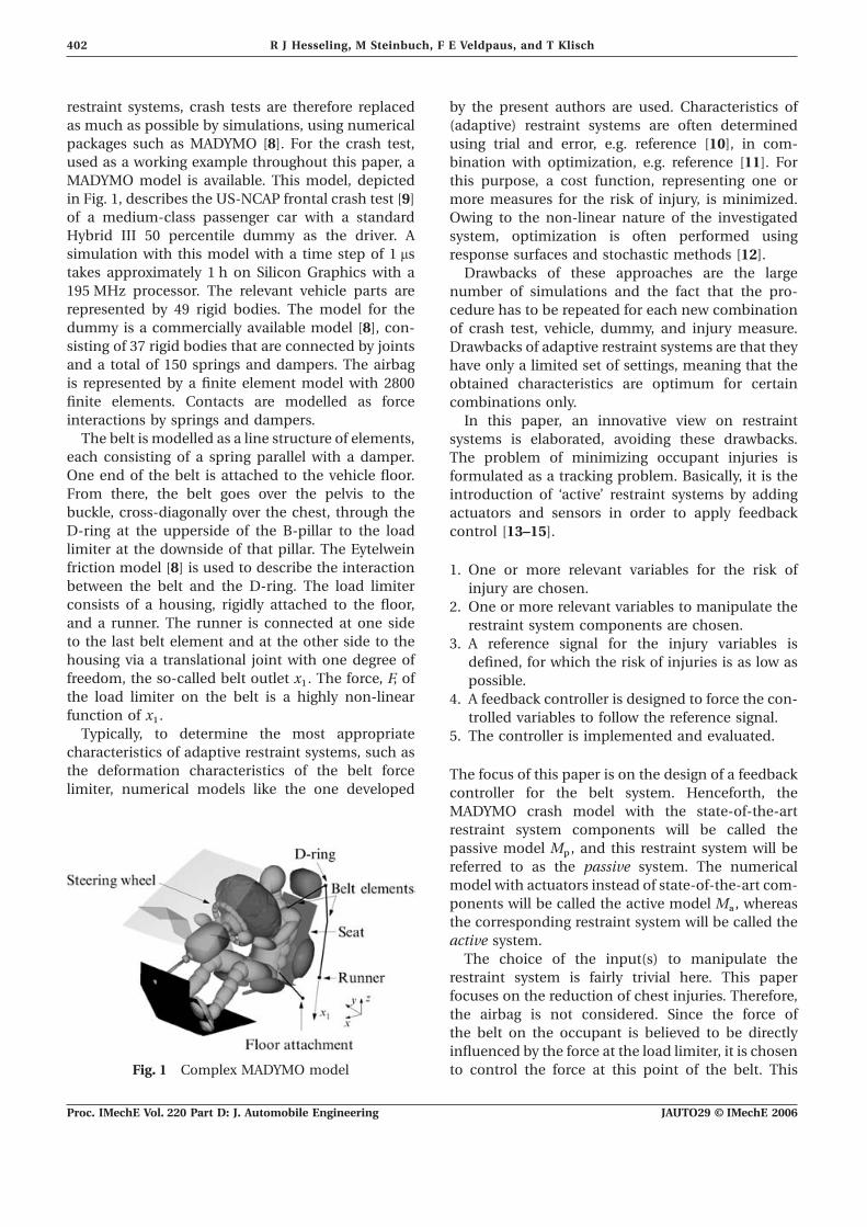
restraint systems, crash tests are therefore replaced by the present authors are used. Characteristics ofas much as possible by simulations, using numerical (adaptive) restraint systems are often determinedpackages such as MADYMO [8]. For the crash test, using trial and error, e.g. reference [10], in com-used as a working example throughout this paper, a bination with optimization, e.g. reference [11]. ForMADYMO model is available. This model, depicted this purpose, a cost function, representing one orin Fig. 1, describes the US-NCAP frontal crash test [9] more measures for the risk of injury, is minimized.of a medium-class passenger car with a standard Owing to the non-linear nature of the investigatedHybrid III 50 percentile dummy as the driver. A system, optimization is often performed usingsimulation with this model with a time step of 1 ms response surfaces and stochastic methods [12].takes approximately 1 h on Silicon Graphics with a Drawbacks of these approaches are the large195 MHz processor. The relevant vehicle parts are number of simulations and the fact that the pro-represented by 49 rigid bodies. The model for the cedure has to be repeated for each new combinationdummy is a commercially available model [8], con- of crash test, vehicle, dummy, and injury measure.sisting of 37 rigid bodies that are connected by joints Drawbacks of adaptive restraint systems are that theyand a total of 150 springs and dampers. The airbag have only a limited set of settings, meaning that theis represented by a finite element model with 2800 obtained characteristics are optimum for certainfinite elements. Contacts are modelled as force combinations only.interactions by springs and dampers. In this paper, an innovative view on restraint
The belt is modelled as a line structure of elements, systems is elaborated, avoiding these drawbacks.each consisting of a spring parallel with a damper. The problem of minimizing occupant injuries isOne end of the belt is attached to the vehicle floor. formulated as a tracking problem. Basically, it is theFrom there, the belt goes over the pelvis to the introduction of ‘active’ restraint systems by addingbuckle, cross-diagonally over the chest, through the actuators and sensors in order to apply feedbackD-ring at the upperside of the B-pillar to the load control [13–15].limiter at the downside of that pillar. The Eytelweinfriction model [8] is used to describe the interaction 1. One or more relevant variables for the risk ofbetween the belt and the D-ring. The load limiter injury are chosen.consists of a housing, rigidly attached to the floor, 2. One or more relevant variables to manipulate theand a runner. The runner is connected at one side restraint system components are chosen.to the last belt element and at the other side to the 3. A reference signal for the injury variables ishousing via a translational joint with one degree of defined, for which the risk of injuries is as low asfreedom, the so-called belt outlet x
1. The force, F, of possible.
the load limiter on the belt is a highly non-linear 4. A feedback controller is designed to force the con-function of x
1. trolled variables to follow the reference signal.
Typically, to determine the most appropriate 5. The controller is implemented and evaluated.characteristics of adaptive restraint systems, such asthe deformation characteristics of the belt force The focus of this paper is on the design of a feedbacklimiter, numerical models like the one developed controller for the belt system. Henceforth, the
MADYMO crash model with the state-of-the-artrestraint system components will be called thepassive model M
p, and this restraint system will be
referred to as the passive system. The numericalmodel with actuators instead of state-of-the-art com-ponents will be called the active model M
a, whereas
the corresponding restraint system will be called theactive system.
The choice of the input(s) to manipulate therestraint system is fairly trivial here. This paperfocuses on the reduction of chest injuries. Therefore,the airbag is not considered. Since the force ofthe belt on the occupant is believed to be directlyinfluenced by the force at the load limiter, it is chosen
Fig. 1 Complex MADYMO model to control the force at this point of the belt. This
403Identification and control of a vehicle restraint system
is realized by replacing the load limiter with an Observations as reported in references [25] and [26]and confirmed by simulations with the crash modelsactuator, exerting a force F in the direction of the
belt outlet x1
in Fig. 1. Mp
and Ma
show that, during frontal crashes, thehead and the chest of the occupant move forwardsThe choice of an appropriate injury measure is far
from trivial [16, 17]. For the intended online control, along an almost straight line. These observationslead to the choice of the very simple crash model ofa measure based on a continuously measurable
signal is desired. Here, the maximum of the absolute Fig. 2 as the starting point for the derivation of thereference signal.value of the chest acceleration c is chosen as
the injury measure to be minimized. Hence, this In this figure, xveh
(t) and c(t) denote the forwarddisplacement of the vehicle and the chest at time tacceleration is the output of the system.
Implementation of the proposed concept in a real- with xveh
(0)=c(0)=0 at the start of the crash att=0. For t∏0, the dummy is in contact with theworld vehicle is not possible yet, mainly because the
required sensing and actuating devices do not exist. back of the seat, so xveh
(0)= c(0)=v0, where v
0is
the initial vehicle velocity. The crash is considered toHowever, developments towards necessary com-ponents have been initiated. Haß and Bertram [18] be finished when the forces on and the accelerations
of the dummy have become negligible. A simulationrecently introduced an electric actuator for the beltforce. In addition, a patent was granted for an with M
pshows that the belt force is less than 1 kN
and that the absolute chest acceleration is less thanhydraulic actuator [19]. In addition, van Poppel [20]has been granted a patent for an actuator for the 50 m/s2 for t100 ms. Therefore, t=t
e=100 ms is
adopted as the end of the crash.belt force, based on piezoelements. Furthermore,sensors for the occupants’ position relative to the The reference signal r
chas to guarantee that the
maximum of the absolute value of the controlledinner vehicle parts do exist [21]. Breed [22] discussesintelligent sensors to determine the severity of the chest acceleration is minimal if the tracking error
e=rc− c is 0 for all tµ[0, t
e]. This is the case if r
ciscrash.
The paper is organized as follows. The deter- equal to the average of the vehicle acceleration, xveh
,over the time interval [0, t
e]. Unfortunately, this ismination of the reference signal is described in
section 2. Section 3 focuses on the derivation of not possible because the reference signal rc
also hasto account for the following constraints.simple models suitable for controller design. The
actual controller design and evaluation are discussed1. The chest cannot move through the back of the
in section 4. The design approach is elucidated inseat, so c(t)−x
veh(t)0 for all t0.
these sections only for one combination, i.e. the2. The chest velocity is equal to or lower than the
input F, the output c, the US-NCAP frontal crash test,vehicle velocity at time t=t
e, so c(t
e)− x
veh(t
e)∏0.
and a middle-class vehicle with an average male3. The chest may not collide with the steering wheel,
dummy as the driver, but it is applicable to otherso c(t)−x
veh(t)<l
0for all t0, where l
0is the
situations also. This is shown in section 5. Moreinitial distance between the chest and the steer-
specifically, the airbag is taken into account anding wheel.
bounds on the belt force are introduced. It is shownthat only the reference signal has to be modified During the first phase of the crash, the vehicle
deceleration is smaller than the average deceleration.to obtain a high performance of the controlledsystem. Section 6 gives conclusions and some Hence, it is impossible to make the controlled chest
deceleration larger than the vehicle deceleration inrecommendations for future research.this crash phase, since the dummy would movethrough the back of the seat. Therefore, from t=0
2 REFERENCE SIGNAL
An important requirement for the reference signal rc
for the chest acceleration c is that, in case of perfecttracking, the maximum chest acceleration is mini-mized. Approaches to determine a suitable referencesignal are discussed in references [23] and [24].Unfortunately, for present purposes, the referencesignal has to account for a number of additionalconstraints on the dummy motion, meaning that
Fig. 2 Simple one-dimensional kinematic modelanother approach is necessary.
404 R J Hesseling, M Steinbuch, F E Veldpaus, and T Klisch
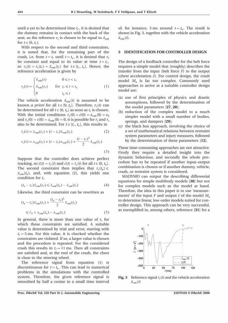
until a yet to be determined time tl, it is desired that of, for instance, 5 ms around t=t
e. The result is
shown in Fig. 3, together with the vehicle accelerationthe dummy remains in contact with the back of theseat, so the reference r
cis chosen to be equal to x
vehx
veh(t).
for tµ[0, tl].
With respect to the second and third constraints,it is noted that, for the remaining part of the 3 IDENTIFICATION FOR CONTROLLER DESIGNcrash, i.e. from t=t
luntil t=t
e, it is desired that r
cbe constant and equal to its value at time t=t
l, The design of a feedback controller for the belt force
requires a simple model that (roughly) describes theso rc(t)= r
c(tl)= x
veh(tl) for tµ[t
l, t
e]. Hence, the
reference acceleration is given by transfer from the input (belt force F) to the output(chest acceleration c). For control design, the crashmodel M
ais far too complex. Commonly used
approaches to arrive at a suitable controller designrc(t)=G xveh(t) 0∏t<t
l
xveh(tl) for tl∏t<te
0 te∏t
(1)model are:
(a) use of first principles of physics and drasticThe vehicle acceleration x
veh(t) is assumed to be assumptions, followed by the determination of
known a priori for all tµ[0, te]. Therefore, r
c(t) can the model parameters [27, 28];
be determined for all tµ[0, te] as soon as t
lis chosen. (b) reduction of the complex model to a much
With the initial conditions rc(0)= c(0)= x
veh(0)=v
0 simpler model with a small number of bodies,and r
c(0)=c(0)=x
veh(0)=0, it is possible for r
cand r
c springs, and dampers [29];also to be determined. For tµ[t
l, t
e], this results in (c) the black box approach, involving the choice of
a set of mathematical relations between restraintrc(t)= xveh(tl)+(t−t
l)xveh(tl) (2)
system parameters and injury measures, followedby the determination of these parameters [12].r
c(t)=xveh(tl)+(t−t
l)xveh(tl)+
(t−tl)2
2xveh(tl)
These time-consuming approaches are not attractive.(3) Firstly they require a detailed insight into the
dynamic behaviour, and secondly the whole pro-Suppose that the controller does achieve perfectcedure has to be repeated if another input–outputtracking, so c(t)=r
c(t) and c(t)=r
c(t) for all tµ[0, t
e].
combination is chosen or if another dummy, vehicle,The second constraint then implies that rc(t
e)∏
crash, or restraint system is considered.xveh
(te), and, with equation (2), this yields one
MADYMO can output the describing differentialcondition for tl equations for simple multibody models [30] but not
(te−tl)xveh(tl)∏ xveh(te)− xveh(tl) (4) for complex models such as the model at hand.
Therefore, the idea in this paper is to use ‘measure-Likewise, the third constraint can be rewritten asments’ of the input F and output c of the model M
ato determine linear, low-order models suited for con-(te−t
l)xveh(tl)+
(te−tl)2
2xveh(tl) troller design. This approach can be very successful,
as exemplified in, among others, reference [31] for a∏l
0+xveh(te)−xveh(tl) (5)
In general, there is more than one value of tl
forwhich these constraints are satisfied. A suitablevalue is determined by trial and error, starting withtl=5 ms. For this value, it is checked whether the
constraints are violated. If so, a larger value is chosenand the procedure is repeated. For the consideredcrash this results in t
l=11 ms. Then all constraints
are satisfied and, at the end of the crash, the chestis close to the steering wheel.
The reference signal from equation (1) isdiscontinuous for t=t
e. This can lead to numerical
problems in the simulations with the controlledsystem. Therefore, the given reference signal is Fig. 3 Reference signal r
c(t) and the vehicle acceleration
xveh
(t)smoothed by half a cosine in a small time interval
405Identification and control of a vehicle restraint system
fermentation process and reference [32] for a slab time tj, and DF
iis the step size. The corresponding
output perturbation dcij
(t) is scaled with the step sizereheating furnace.The ‘measurements’ are obtained from simulations DF
i, resulting in the normalized output perturbation
dcij
(t)=dcij
(t)/DFi. Figure 6 gives some simulationwith M
aduring which a small perturbation dF is
added to a known belt force Fp
, resulting in the per- results for step sizes in the range from 10 N to 200 N,applied at t
1=20 ms.turbed input F=F
p+dF. The perturbed output is
given by c= cp+ c, where c
pis the chest acceleration Since the active model M
ais non-linear, it is to be
expected that the normalized output perturbationsdue to the force Fp
. To find a suitable force Fp
as afunction of time, the belt force is measured during a will not be the same for all sizes DF
i, nor for all points
of application tj. From Fig. 6 it can be seen that non-simulation with the passive model M
p. The obtained
force in the belt at the load limiter is depicted in linearities become important for step sizes largerthan 100 N, whereas the normalized output per-Fig. 4, whereas the obtained so-called passive chest
acceleration cp
is given in Fig. 5. This figure also gives turbations for sizes equal to or smaller than 50 N arevery similar. Hence, it seems reasonable and possiblethe chest acceleration c obtained for the case where
the passive belt force Fp
is used as a prescribed to linearize Ma
locally at the point of applicationt
1=20 ms and to use the normalized output per-actuator force in the active model M
a. As expected,
this acceleration is equal to the passive chest turbations to determine a linear, simple controllerdesign model.acceleration c
p.
The preferred input perturbation, an impulse [27], The results in Fig. 6 show a striking oscillatorybehaviour for t>37 ms. A detailed analysis of simu-cannot be used since numerical packages like
MADYMO cannot deal with impulses. The alternative lation results shows that this behaviour is caused bya sign change of the friction in the joint between theof harmonic perturbations is not attractive since
it requires an extensive set of time-consuming left clavicle and the left upper arm. It is assumed thatthis friction does not significantly influence the con-simulations with M
ato cover the frequency range of
interest. Therefore, and to facilitate a quick and troller design model to be determined, and thereforeM
ais modified by eliminating this friction. Theintuitive interpretation of the results, stepwise per-
turbations dFij
(t)=DFie(t−t
j) are used. Here, e(t−t
j) normalized output perturbations dc
i,1for five input
perturbations with step sizes DF1=10 N, DF
2=20 N,represents a unit step at the point of application or
DF3=30 N, DF
4=40 N, and DF
5=50 N, applied at
t1=20 ms and obtained with the modified model,
are given in Fig. 7.At t#39 ms and t#42 ms, indicated by A and B
in Fig. 7, the response still shows a non-smoothbehaviour. This implies that only the part of theoutput perturbations for t∏39 ms can be used todetermine a linear controller design model.
To minimize the effect of computational noise, theobtained five normalized output perturbations areaveraged. The averaged normalized perturbation
406 R J Hesseling, M Steinbuch, F E Veldpaus, and T Klisch
of these responses is limited owing to the non-smooth behaviour of M
aat t#39 ms. For dc:
3, the
usable time span is only 9 ms. It is expected that thisis too short, so the response for t
3=30 ms is left out
of consideration in the sequel.Given the step response of a linear model, a variety
of techniques exists to determine the order and themodel parameters, e.g. reference [27]. For the presentpurposes, a technique is desired that can deal withstep responses, measured over a time span shorterthan the time required to attain the steady state. Thisis possible, for instance, with the modified approxi-Fig. 7 Normalized output perturbation dc
i,1for
mate realization method [33, 34]. This method ist1=20 ms with the modified model
attractive since it supplies information to choose theorder of the model and it can directly estimate the
dc:j(t) of the chest acceleration
model parameters. Here, the modified approximaterealization algorithm, as outlined in reference [35],
dc:j(t)=
1
5∑5
i=1
dci,j
(t)
DFi=
1
5∑5
i=1dci,j
(t) (6) is applied.The transfer functions of the linear models,
is seen as the normalized output perturbation at obtained with this method applied to dc:1
and dc:2,
t=tj
and is used to determine a controller design are denoted by H1(s) and H
2(s). Singular value
model. decomposition is performed on the transformedTo investigate whether the simple model, obtained Hankel matrices, constructed from dc:
j(t) with
from the output perturbations at time t1, reflects the tµ(t
j, 39 ms), j=1, 2. The five largest singular values
relevant dynamic behaviour at other operating points, are given in Table 1. Based on these results, the linearthe outlined procedure is applied at different points models to be constructed are established as secondof application t
jin the interval 20–35 ms. The lower order.
bound of this interval is based on the observation Next, a discrete-time model is derived, transformedthat, in the passive system, it takes nearly 20 ms into a continuous-time, state-space model (using thefor the belt to settle, whereas the upper bound matched pole-zero method [36]) and written inis a consequence of the mentioned non-smooth transfer function formbehaviour of M
aaround t=39 ms. Apart from
t1=20 ms, two other points of application t
2=25 ms H
j(s)=Kst
1−s/2pz
(s/2p fn)2+2fs/2p fn+1(7)
and t3=30 ms are chosen. The averaged normalized
perturbations dc:1, dc:
2, and dc:
3for t
1, t
2, and t
3are
where Kst
is the static gain, fn
is the undamped eigen-shown in Fig. 8.
frequency, f is the damping factor, and 2pz is systemTo ensure that the small, but possibly significant,
zero. The obtained model parameters are given indifferences between these responses are accounted
Table 2.for during controller design, a linear model is derivedfor dc:
407Identification and control of a vehicle restraint system
From the Bode diagrams in Fig. 9 it can be con- desired 5 per cent settling time t5%
. Based on themaximum of the vehicle deceleration, and to avoidcluded that, in the frequency range of interest, i.e.
from 5 Hz to 5 kHz, the differences between the unrealistic requirements for the actuator, ratherarbitrarily e
max=20 m/s2 and t
5%=11 ms are chosen.obtained linear models are small.
The bandwidth fBW
, defined as the 0 dB cross-over frequency of the open-loop transfer functionH(s)C(s), is related to the settling time. The desired4 CONTROLLER DESIGNbandwidth is lower bounded by the duration of thecrash test. The aim is a bandwidth as low as accept-In this paper, only feedback control is considered.
Feedforward control is not attractive or even possible able, because then the actuator specifications will beless demanding than for a high bandwidth. For aat the moment, because the crash model M
ais too
complex as a basis for inverse dynamics and no standard, linear, second-order system with dampingfactor f, a simple, approximate relation between thesufficiently accurate inverse crash model is yet avail-
able. Besides, the controller to be designed has to be bandwidth and the settling time is given by [38]robust and applicable without major changes for awide variety of crashes and occupants. This requires fBW#
3
2pt5%f(8)
some kind of feedback.From the wide variety of feedback controller design Using this relation with t
5%=11 ms, the minimum
techniques, e.g. reference [37], the classical loop- bandwidth is then 69 Hz and 60 Hz for the systemsshaping technique, e.g. references [38] and [39], is with transfer function H
1(s) and H
2(s) respectively.
chosen. This technique is widely accepted as a start- The requirement |e|∏emax
for the tracking erroring point for controller design, the controller output is translated into a requirement for the sensitivitycan intuitively be understood, and the structure of function S(s), describing the closed-loop transferthe controller is well known. The transfer function from reference r
cto tracking error e=r
c− c
of the controller will be denoted by C(s).The controller has to satisfy a number of design
Sj(s)=
1
1+Hj(s)C(s)
(9)criteria concerning, among others, stability and per-formance. The desired stability is formulated here in
The translation is not trivial. First of all it is notedterms of the gain margin (GM) and phase marginthat, for t<t
l, it is no problem if the tracking error(PM). To account for the lack of accurate knowledge
is larger than emax
, since then the absolute chestabout model errors, relatively high values GM=3accelerations are moderate or small and exceedingand PM=45° are aimed for. Since the differences ine
maxwill in general not increase the maximumthe local dynamics, as characterized by the transfer
absolute chest acceleration. For tl∏t∏t
e, thefunctions H
1(s) and H
2(s), are fairly small and
reference acceleration is constant and, at least for thebecause the Nyquist plots are very smooth, extraconsidered crash, approximately equal to−200 m/s2.measures to ensure additional robustness are omitted.This means that the allowable relative tracking errorThe desired performance is formulated in terms ofis then 10 per cent or −20 dB. Using the method ofa maximum allowable tracking error e
maxand a
Welch’s averaged, modified periodogram [27, 36] onthe chest acceleration c
pit turns out that almost
95 per cent of the energy is stored in componentswith frequencies lower than 100 Hz. It is thereforerequired that |S
j(2pj f ) |∏−20 dB for f∏100 Hz.
From the Bode diagram in Fig. 9 it can be con-cluded that a properly tuned PI controller incombination with a second-order low-pass filtermay be sufficient [39]
C(s)=PA1+ 1
tIsB v2fs2+2ffvfs+v2f
with vf=2p ff
(10)
where P and tI
are the parameters of the PI controllerFig. 9 Bode diagrams for the transfer functions H1(s)
408 R J Hesseling, M Steinbuch, F E Veldpaus, and T Klisch
the undamped eigenfrequency of the low-pass filter. the controlled chest acceleration c and in Fig. 13for the required belt force F. It can be observed thatThis filter effectively suppresses the (computational)
noise in the output of the MADYMO model. the maximum of the absolute chest acceleration hasdecreased from 50 g for the passive system to 21 gA first choice for the controller parameters, using
the transfer function H1(s) and aiming at a bandwidth for the active system.
The results indicate a stable and sufficiently robustof 69 Hz, shows that the desired disturbance reductionis not achieved. Next, the bandwidth is increased closed loop. Interpreting the tracking error during
the first phase of the crash for t∏11 ms, it seemsuntil a controller is found that satisfies all designcriteria. This turns out to be the case for a band- that the settling time t
5%is achieved. The error at
width of 400 Hz for H1(s) and 468 Hz for H
2(s). t=11 ms is approximately 4 per cent.
The controller parameters are P=100 N s2 m and At t#35 ms, the maximum allowable trackingt
I=160 Hz. The Bode diagram of the resulting error e
maxis slightly violated, indicated by A in Fig. 12.
sensitivity functions S1(s) and S
2(s) and the interest- A detailed investigation of the forces in the belt
ing part of the Nyquist plot of H1(s)C(s) and of system shows that, at t#35 ms, the velocity of the
H2(s)C(s) are shown in Figs 10 and 11 respectively. belt over the D-ring changes sign. As a result of this,The obtained controller is combined with the the friction force between the belt and the D-ring
active system Ma. Some results of the simulation starts to contribute to restrain the dummy instead of
with this closed-loop system are given in Fig. 12 for counteracting it. This phenomenon can be observedin Fig. 13, where the force F
effin the belt between the
D-ring and the left clavicle of the dummy is shownby the dash-dotted line.
Until t=25 ms, high belt forces are needed to keepthe dummy in contact with the back of the seat. Inthis period, the dummy is even slightly pushed back.After t=25 ms, the dummy starts to move forwardrelative to the vehicle. Then, the velocity of the beltFig. 10 Modulus of the sensitivity functions S
1(s) and
S2(s) over the D-ring changes sign. These two phenomena
cause the belt force to decrease significantly aroundt#35 ms.
Figure 13 also clearly shows that the exerted beltforce is significantly higher in the controlled case.This may be due to the fact that the airbag is notinflated in this case. For modern cars involved in aserious frontal crash, this is unrealistic. In section 2,the airbag will be accounted for.
The results in the preceding part of this sectionindicate that the transfer functions H
1(s) and H
2(s)
are sufficiently accurate for controller design. More
Fig. 11 Nyquist plots of H1(s)ΩC(s) and H
2(s)ΩC(s)
Fig. 13 Time history of Fp
(t) and of F(t)Fig. 12 Time history of c(t) and of cp
409Identification and control of a vehicle restraint system
than that, these results suggest that the linear models relatively high, probably leading to undesired injuries,do make sense even for operating points of the not accounted for by the adopted measure for theclosed-loop system. To evaluate these observations, risk of injury. For example, a belt force of 15 kNclosed-loop identification is performed (see Fig. 14). (see Fig. 13) probably leads to a broken clavicle orStepwise perturbations dF(t)=DFe(t−t) are added to rib. Besides that, actuators that are able to apply athe controller output F at two points of application force increasing from 0 to 8 kN within 2 ms do nott=t
1and t=t
2. (yet) exist.
An analysis of the perturbed belt force F and per- In this section, these aspects are taken into account.turbed chest acceleration c suggests a locally linearbehaviour. Next, the transfer functions from dF to F 1. A finite element model of the airbag is includedand from dF to c are determined, both for t=15 ms. in the active model M
a. This airbag is passive,
For this point of time, the closed system is in meaning that the gas flow into and out of the bagalmost the same state as the passive model at point behaves as in the passive system.of time t=20 ms. From these functions, the transfer 2. Bounds on the maximum belt force and its timefunctions H∞(s) of the local model at the operation derivative are implemented by clipping thepoints of the controlled system at time t=15 ms can controller output.be derived, e.g. reference [40]. The Bode diagrams ofthe resulting H∞(s) and the Bode diagram of H
1(s) and Load limiters are designed with the objective of limit-
H2(s) are shown in Fig. 15. ing the force applied to the dummy by the belt. TheseFor low frequencies and around the bandwidth
limits vary from 2 to 7 kN [41–43], depending onf
BW=400 Hz these models are quite similar to
dummy mass or crash test characteristics. Here, athose for the passive system, whereas the operating
bound of Fmax=6 kN is adopted. Bounds on the time
points are quite different. This suggests that the non-derivative of the belt force |F(t) | are rarely discussed
linearity of the system is fairly weak. The bandwidthin the literature. Therefore, the time history F
p(t) of
fBW
of the open-loop system of the controller C(s)the belt force for the passive belt system is analysed.combined with H∞(s) is 280 Hz, suggesting that theThe maximum of the absolute rate per millisecond,actual bandwidth for an actuator may be even loweri.e. max |F
p(t) |, is approximately 1.5 kN/ms. Hence, athan the 468 Hz earlier determined.
bound of |Fmax|=1.5 kN/ms seems reasonable.
Owing to the bounds on the belt force, it will notbe possible to track the reference signal with5 TOWARDS A MORE REALISTIC RESTRAINTsufficient accuracy. In addition, the constraints onSYSTEMthe dummy motion will be violated if the referencesignal of the previous sections is used. Hence, theIn the preceding sections, the restraint system wasreference signal has to be modified. By trial and error,not very realistic. First of all, the dummy was onlya constant reference signal, r
c(t)= c
des, is used, whererestrained by the belt. Secondly, the belt forces were
cdes
is the acceleration to be determined. Again, thereference signal is smoothed around t=t
e. To prevent
integral wind-up problems, the integral controller isreset when the tracking error passes zero for the firsttime [44].
Starting with an initial value of−200 m/s2 for cdes
,a simulation with the closed-loop system, including
Fig. 14 Configuration for closed-loop identification the bounds on the controller output, is performed.The simulation results show that the constraintson the dummy motion are violated. Therefore, thevalue of c
desis decreased until the motion constraints
are satisfied. After a few simulations, a value ofc
des=−230 m/s2 is found. The controlled chest
acceleration and the required belt force are shownin Figs 16 and 17 respectively. Until t#35 ms,the required belt force and the controlled chestacceleration are fully dominated by the imposedFig. 15 Modulus of the transfer functions H∞(s), H
410 R J Hesseling, M Steinbuch, F E Veldpaus, and T Klisch
The problem, normally solved by optimization, istranslated here into a tracking problem. The referencesignal has to reflect the lowest possible occupantinjuries and account for a number of constraints onthe dummy motion and belt force. The designapproach embraces three main steps: the deter-mination of the reference signal, the derivation oflinear controller design models, and the actualcontroller design.
The local dynamic behaviour, derived from theresponse in the chest acceleration on small per-turbations in the belt force, is linear and secondorder and weakly depends on the operating point.Fig. 16 Chest acceleration c(t) for the controlled
system with a passive airbag ‘Measurements’ over a short time span are shown tobe sufficient for a suitable identification of therequired linear models. Control design based onthese models resulted in a PI controller in com-bination with a second-order low-pass filter. Therequired bandwidth of the controller is in the range200–400 Hz. Simulations with the controlled systemshow that the occupant injuries could be reducedsignificantly if appropriate sensors and actuatorswere available.
The presented approach for restraint controllerdesign is powerful because of its simplicity andbecause of its widely known and accepted techniquefor controller design. The approach is very versatile,as long as a suitable reference signal can be deter-Fig. 17 Belt force F(t) for the controlled system with amined. It has been shown that the approach can bepassive airbagseen as a design expedient, i.e. as a basis for thedesign of controllers for other than the consideredIn comparison with the case without the airbag,restraint systems.the chest acceleration and the belt force are more
Research has been initiated to investigate thenoisy, especially for t>50 ms. This is caused by thepossibility of using the same approach to manipulateinteraction of the chest with the finite element modelthe belt, aiming at reduction in the chest deflection.of the airbag. The time history of the effectivePredictive control is being implemented to deal withrestraint force F
effin the belt between the D-ring and
constraints that cannot simply be translated intothe left clavicle is shown by the dash-dotted line inbounds on the reference signal. More insight has toFig. 13. It can be seen that, for the active system withbe obtained into the relation between the injurythe passive airbag and extra bounds on the belt force,measures, injury mechanisms, and the behaviour ofthe effect of the friction in the D-ring on F
effis much
the airbag and the belt. This insight is necessarysmaller. A very important result of the simulations isfor the design of controllers simultaneously tothat the required force in the first phase of the crashmanipulate the airbag and belt with the purpose ofand the maximum of this force are signifcantlyminimizing more than one injury measure.smaller than for the controlled system without the
For several reasons, the designed controller cannotairbag, whereas the maximum of the absolute chestyet be implemented in a real vehicle. First of all, noacceleration is only slightly increased.appropriate hardware exists as yet. Secondly, theformulation of the control problem as a trackingproblem implies that the reference signal has to6 CONCLUDING REMARKSbe known at the very beginning of the crash. Inthe current approach, this means that the vehicleIn this paper, an approach is presented for the designdeceleration during the whole crash has to be avail-of a belt force controller to reduce the maximum
absolute chest acceleration as much as possible. able a priori. It is a topic of future research how to
411Identification and control of a vehicle restraint system
6 Clute, G. Potentials of adaptive load limitation. Indetermine, in the first few milliseconds of a crash, aProceedings of 17th International Technical Con-suitable reference signal, using measurements of, forference on Enhanced Safety of Vehicles, Amsterdam,instance, the initial velocity, v
0, the initial distance,
2001, paper 134 (NHTSA, Washington, DC).l
0, between the occupant and the steering wheel, 7 Marklund, P. O. and Nilsson, L. Optimization of
and the vehicle decelerations in these first few airbag inflation parameters for the minimization ofmilliseconds. out of position occupant injury. Comput. Mechanics,
A further factor is that the present-day actuators 2003, 31(5), 496–504.8 TNO Automotive MADYMO Version 5.4 manuals,cannot realize the belt forces that are prescribed by
1999 (TNO Road-Vehicles Research Institute, Delft).the controller, especially because their bandwidth is9 NHTSA Laboratory test procedure frontal impacttoo low. Besides this, the prescribed forces are very
testing, 1999 (US Department of Transportation).high. This is a problem not only for the actuator but10 Schaub, S. and Bosio, A. C. Intelligente
also for the occupant since these forces may result Ruckhaltesysteme fur den europaischen Markt.in injuries such as a broken clavicle. This again Tagung der innovativer Insassen- und Partnerschutzunderlines the need for future research on a more im PKW, Berlin, 1998, pp. 145–153 (VDI, Dusseldorf).realistic reference signal that not only reflects the 11 Hong, J. H., Mun, M. S., and Song, S. H. An optimum
design methodology development using a statisticalmentioned constraints on the occupant speed andtechnique for vehicle occupant safety. Proc. IMechE,displacement at the end of the crash and on thePart D: J. Automobile Engineering, 2001, 215(D4),maximum of the absolute chest acceleration but795–801.also accounts for requirements with respect to the
12 Montgomery, D. C. Design and analysis of experi-maximum of the belt force. ments, 5th edition, 2001 (John Wiley & Sons, New
York).13 Hesseling, R. J., Steinbuch, M., Veldpaus, F. E., and
Klisch, T. Control design for safety restraint systems.ACKNOWLEDGEMENTSIn Proceedings of 3rd International Conference onControl Theory and Applications, Pretoria, 2001,
The authors acknowledge the support of the pp. 440–444 (IEEE, New York).Advanced Safety Engineering group, EG-22, of the 14 Hesseling, R. J. Active restraint systems – feedbackBMW Group for facilitating this research, especially control of occupant motion, PhD Dissertation, Tech-
nische Universiteit Eindhoven, The Netherlands,Dipl.-Ing. Hans Baldauf and Dr-Ing. Sven Link.2004.
15 Cooper, J., Lemmen, P., and van Schie, C.Effectiveness of real time control for active restraintsystems in frontal crashes. In Proceedings of Air-REFERENCESbag 2004, Karlsruhe, 2004, paper 8 (FrauenhoferGesellschaft, Germany).1 NHTSA Traffic safety facts 2001 – occupant protection,
16 Kent, R., Patrie, J., and Benson, N. The hybrid III2001 (US Department of Transportation).dummy as a discriminator of injurious and non-2 McCarthy, M. G., Chinn, B. P., and Hill, J. The effectinjurious restraint loading. In Proceedings of 47thof occupant characteristics on injury risk and theAnnual Meeting of the AAAM, Lisbon, 2003,development of active-adaptive restraint systems. Inpp. 51–75 (AAAM, Barrington, Illinois).Proceedings of 17th International Technical Con-
17 Kallieris, D., Rizzetti, A., and Mattern, R. Onference on Enhanced Safety of Vehicles, Amsterdam,the synergism of the driver airbag and the2001, paper 314 (NHTSA, Washington, DC).3-point belt in frontal collisions. In Proceedings3 Johannessen, H. G. and Mackay, M. Why ‘intelligent’of 39th Stapp Car Crash Conference, San Diego,automotive occupant restraint systems? In Pro-1995, pp. 389–401 (SAE International, Warrendale,ceedings of the 39th Annual Meeting of the AAAM,Pennsylvania).Chicago, 1995, pp. 519–525 (AAAM, Barrington,
18 Haß, C. and Bertram, T. Mechatronischer Gurt-Illinois).straffer – synergien zwischen aktiver und passiver4 Bendjellal, F., Walfisch, G., Steyer, C., and ForetSicherheit. Special issue of ATZ//MTZ/AutomotiveBruno, J. Y. The combination of a new air bagEngineering Partners, 2003, Vol. 9, 64–71.technology with a belt load limiter. In Proceedings
19 Smithson, A., Blackadder, D., Taylor, J., Downie, A.,of 16th International Technical Conference onHarte, J., and Park, A. Load limiting device for a seatEnhanced Safety of Vehicles, Windsor, 1998, paperbelt. US Pat. 6.196.589, 2001.98-S5-O-14 (NHTSA, Washington, DC).
20 van Poppel, J. A. Piezoelectric coupler for variably5 Hontschik, H., Muller, E., and Ruter, G. Necessitiescoupling two bodies and joint incorporating theand possibilities of improving the protective effect ofcoupler. US Pat. 6.384.518, 2002.three-point seat belts. In Proceedings of 21st Stapp
21 Birch, S. Pre-safe headlines S-class revisions.Car Crash Conference, New Orleans, 1977, pp. 795–831 (SAE International, Warrendale, Pennsylvania). Automot. Engng Int., 2003, 11(1), 15–17.
412 R J Hesseling, M Steinbuch, F E Veldpaus, and T Klisch
22 Breed, D. S. A smart airbag system. In Proceedings Math., 2000, 121(1–2), 331–354, Special issue onNumerical Analysis in the 20th Century: Vol. I,of 16th International Technical Conference onApproximation Theory.Enhanced Safety of Vehicles, Windsor, 1998 (NHTSA,
36 The student edition of MATLAB Version 5.3, 1997Washington, DC).(The Mathworks, Upper Saddle River, New Jersey).23 Heym, A. and Adomeit, H. D. Das intelligente
37 Astrom, K. J. and Hagglund, T. PID controllers:Ruckhaltesystem: ein neues Konzept zur Begrenzungtheory, design, and tuning, 2nd edition, 1995der Komplexitat. Tagung der innovativer Insassen-(Instrument Society of America, North Carolina).und Partnerschutz im PKW, Berlin, 1998,
38 Driels, M. Linear control systems engineering, 1stpp. 260–297 (VDI, Dusseldorf).edition, 1996 (McGraw-Hill, Singapore).24 Ikels, K., Maurer, C., and Klisch, T. Innovative
39 Steinbuch, M. and Norg, M. L. Advanced motionEnergiemanagement Methoden zur Analyse undcontrol: an industrial perspective. Eur. J. Control,Verbesserung von Insassenschutzsystemen. Tagung1998, 4, 278–293.der innovativer Insassen- und Partnerschutz im
40 van den Hof, P. M. J. and Schrama, R. J. P.PKW, Berlin, 2001, pp. 199–234 (VDI, Dusseldorf).Identification and control – closed loop issues.25 Kallieris, D., Conte-Zerial, P. D., and Rizzetti, A.Automatica, 1995, 31(12), 1751–1770.Prediction of thoracic injuries in frontal collisions.
41 Miller, H. J. Injury reduction with smart restraintIn Proceedings of 16th International Technicalsystems. In Proceedings of 39th Annual Meeting ofConference on Enhanced Safety of Vehicles, Windsor,the AAAM, Chicago, 1995, pp. 527–541 (AAAM,1998 (NHTSA, Washington, DC).Barrington, Illinois).26 Mackay, M., Hassan, A. M., and Hill, J. R.
42 Mertz, H. J., Williamson, J. E., and van derObservational studies of car occupants’ positions. InLugt, D. A. The effect of limiting shoulder belt loadProceedings of 16th International Technical Con-with air bag restraint. In Proceedings of 1995ference on Enhanced Safety of Vehicles, Windsor, 1998,International Congress and Exposition, Detroit,paper 98-S6-W42 (SAE International, Warrendale,1995, paper 950886 (SAE International, Warrendale,Pennsylvania).Pennsylvania).27 Ljung, L. System identification – theory for the user,
43 Kramer, F. Passive Sicherheit von Kraftfahrzeugen,2nd edition, 1999 (PTR Prentice-Hall, Upper Saddle1st edition, 1998 (Vieweg, Braunschweig).River, New Jersey).
44 Rundqwist, L. Anti-windup reset for PID controllers.28 Gordon, T. J. and Hopkins, R. Parametric identifi-Preprints of 11th IFAC World Congress, Tallinn, 1990.cation of multibody models for the crash victim
29 Crandall, J. R., Cheng, Z., and Pilkey, W. D. Limit- APPENDIXing performance of seat belt systems for theprevention of thoracic injuries. Proc. IMechE, Part D:
NotationJ. Automobile Engineering, 2000, 214(D2), 127–139.30 van Schie, C. Lineariseren van bewegingsvergelijking c, c, c chest acceleration, velocity,
met betrekking tot multibody-systemen. MSc Thesis, displacementWFW, 92.102, Technische Universiteit Eindhoven,
dc normalized perturbed chestThe Netherlands, 1992.acceleration31 Azimzadeh, F., Galan, O., and Romagnoli, J. A.
dc:j
averaged normalized perturbedOn-line optimal trajectory control for a fermentationchest accelerationprocess using multi-linear models. Comput. Chem.
Engng, 2001, 25, 15–26. e tracking error32 van Ditzhuijzen, G., Staalman, D., and Koorn, A. f frequency
Identification and model predictive control of a slab fn
undamped eigenfrequencyreheating furnace. In Proceedings of 2002 IEEE F belt forceInternational Conference on Control Applications,
Feff
effective belt forceGlasgow, 2002, pp. 361–366 (IEEE, New York).GM, PM gain margin and phase margin33 Kung, S. Y. A new identification and modelH(s) transfer functionreduction algorithm via singular value decompo-K
ststatic gainsition. In Proceedings of 12th Asilomar Conference
on Circuits, Systems and Computers, California, l0
initial distance between the front1978, pp. 705–714 (IEEE, New York). of the chest and the steering
34 Ho, B. L. and Kalman, R. E. Effective construction wheelof linear state-variable models from input/output M numerical crash modelfunctions. In Proceedings of 3rd Annual Allerton Con-
P, tI
controller parametersference on Circuit and System Theory, Monticello,r
c, r
c, r
creference signal for the chest1965, pp. 449–459 (Allerton Conference, Urbana).acceleration, velocity, and35 de Schutter, B. Minimal state-space realization in
linear system theory: an overview. J. Comput. Appl. displacement


![arXiv:1512.01013v1 [math.ST] 3 Dec 2015 · and Beauchamp, 1988), have been utilized towards a Bayesian approach for variable selection. George and McCulloch (1997) used zero inflated](https://static.documents.pub/doc/80x56/5fbdbef162faa51c8c14ec03/arxiv151201013v1-mathst-3-dec-2015-and-beauchamp-1988-have-been-utilized.jpg)


