Page 1
RECENT ADVANCES IN NONLINEAR DYNAMICS AND VIBRATIONS
Identification-based predictive control of semi-active shock-absorbers for adaptive dynamic excitation mitigation
Cezary Graczykowski . Rami Faraj
Received: 1 November 2019 / Accepted: 4 September 2020 / Published online: 20 November 2020
� The Author(s) 2020
Abstract The paper is aimed at detailed discussion
of the Identification-based Predictive Control (IPC)
developed for semi-active fluid-based shock-ab-
sorbers which protect structures and machines against
impact excitations. The problem addressed is the
optimal impact absorption providing adaptive mitiga-
tion of dynamic response of the mechanical system.
The goal of applied control is dissipation of the entire
impact energy and minimization of the impacting
object deceleration during the process. Three proposed
implementations of the IPC are based on sequentially
repeated procedures, which include identification of
excitation parameters and calculation of the valve
opening providing minimization of tracking error of
the optimal path. The presented numerical examples
concerning mitigation of the dynamic excitation
acting on the double-chamber pneumatic shock-
absorber reveal high efficiency and prove robustness
of the proposed control methods. The developed
algorithms are compared against each other in terms
of path-tracking efficiency and character of required
control actions. The most important challenges in
practical implementation of the proposed methods are
indicated.
Keywords Adaptive control � Adaptive Impact
Absorption � Identification-based Predictive Control �Model Predictive Control � Self-adaptive shock-
absorber � Semi-active control
1 Introduction
Dynamic excitations are present in majority of
mechanical systems and as a result the protection
against shock and vibration is still an attractive field of
research and development. Problems of dynamic
excitation mitigation concern various systems such
as aircraft landing gears [1, 2], airdrop systems [3, 4],
emergency landing airbags for drones [5], suspensions
of lunar-planetary landers [6], bumpers of vehicles
[7, 8], road barriers [9], car airbags [10] or protection
of offshore structures [11]. Large variety of shock-
absorbers’ applications leads to numerous technical
solutions, which differ from each other in terms of
construction, involved physical phenomena and com-
plexity of control system. At present, more and more
frequent practice is the use of so-called smart devices,
which are based on functional materials and advanced
control systems, e.g., magneto-rheological energy
absorbers [12–15], electro-rheological dampers
[16, 17], particle impact dampers [18, 19], or pneu-
matic adaptive absorbers with piezoelectric valves
[20]. Simultaneously, advances in the development of
C. Graczykowski (&) � R. Faraj
Institute of Fundamental Technological Research, Polish
Academy of Sciences, Pawinskiego 5B, 02-106 Warsaw,
Poland
e-mail: [email protected]
123
Meccanica (2020) 55:2571–2597
https://doi.org/10.1007/s11012-020-01239-6(0123456789().,-volV)( 0123456789().,-volV)
Page 2
control methods provide higher and higher effective-
ness and reliable, adaptive performance [21–23].
The concept of Adaptive Impact Absorption (AIA)
[24], which was conceived over two decades ago [25],
states an important contribution to the field of dynamic
excitation mitigation. Within the paradigm of AIA the
control strategy applied for mitigation of the system
response assumes three consecutive steps, i.e., iden-
tification of the impact excitation, calculation of
optimal feasible response of the system and realization
of the control scenario in order to obtain desired
process of impact absorption. Such approach has been
successfully applied for a number of impact absorp-
tion problems [26] and methods for identification of
the impact loading can be found in literature [27].
Adaptive impact absorption is often realized with the
used of semi-active absorbers, which are typically
controlled in closed loop with different types of
feedback, e.g., force [28] or acceleration feedback
[29]. Following the AIA approach the value of the
absorber reaction force or alternatively the piston
deceleration is calculated based on the identified
values of excitation parameters [30]. Then, the system
tracks the calculated path until stopping of the
impacting object.
Design of control systems for the AIA approach can
be based on classical methods such as well-known PID
controllers [31–33] or their modern modifications such
as self-regulating fuzzy PD controllers [34]. The
disadvantage of the classical approach is the fact that
system relies on the quality of initial excitation
identification and robustness to possible disturbances
in the impact absorption process is not provided. This
problem was addressed by the authors in previous
papers, where consequences of imprecise initial
identification of the excitation has been revealed
[35], the method providing self-adaptive performance
of the fluid-based absorbers has been introduced [36]
and experimentally validated using drop tests [37].
This paper proposes new control methods, which
are based on the identification of excitation parame-
ters, but in contrast to the original AIA approach the
identification is not treated as a separate process
performed before single calculation of the control
strategy at the beginning of impact absorption process.
On the contrary, system performs iterative identifica-
tion of excitation parameters and updates the control
signal at every control step.
For the sake of clarity the proposed methods are
discussed on the illustrative example of double-
chamber pneumatic shock-absorbers, which together
with hydraulic dampers, represent the wider group of
semi-active fluid-based absorbers and constitute one
of the most basic devices used for adaptive impact
absorption. Such absorbers are typically composed of
two sealed chambers filled with pneumatic or
hydraulic fluid and the controllable (e.g. electro-
mechanical or piezo-electric) valve. In addition, they
are equipped with system of sensors, which enables
measurement of the actual state of the fluid (pressure
and temperature of gas in both chambers) and actual
kinematics of the piston (its acceleration or displace-
ment with respect to the device compartment). More-
over, semi-active shock-absorbers are equipped with
fast controllers, which enable real-time modification
of the actual valve opening and control of the actual
rate of the fluid flow between the chambers. Semi-
active shock-absorbers are typically subjected to two
different types of dynamic excitations: i) impact
excitation caused by object hitting the piston with
initial velocity, ii) external force applied to the piston.
General scheme of semi-active fluid-based shock-
absorber considered in further part of this study is
presented in Fig. 1.
In the case of impact excitation, the objective of
semi-active shock-absorber is to dissipate the entire
impact energy and mitigate the dynamic system
response by minimization of the force generated by
the absorber and minimization of the impacting object
deceleration. In general, such objective can be
achieved by the adjustment of applied level of
generated absorber force to determined impact energy
and by using real-time control of the valve opening to
provide the required mass flow rate of fluid between
both chambers of the device. In the case of hydraulic
shock-absorber, the optimal strategy of impact absorp-
tion provides dissipation of the entire impact energy
with constant value of force maintained until the end
of the stroke. In turn, in the case of pneumatic shock-
absorber, the strategy of optimal impact absorption
requires initial stage of force increase and the stage
when force remains constant until the end of the
process. As a result of applied paradigm of adaptation
and real-time control, the semi-active fluid-based
hydraulic and pneumatic shock-absorbers can be
adjusted to actual dynamic excitation and they surpass
123
2572 Meccanica (2020) 55:2571–2597
Page 3
classical passive shock-absorbers in terms of effi-
ciency and operation robustness.
2 Problem of dynamic excitation mitigation
2.1 Exact and simplified mathematical model
of the system
The basis for development of identification-based
semi-active control methods is exact mathematical
model of the fluid-based shock-absorber, which is
based on the so-called concept of physical modelling
[38]. In this approach the response of the shock-
absorber is described exclusively with the use of
fundamental physical principles, while no phe-
nomenological relations describing global response
and value of generated resistance force are used. In
particular, in the considered case of the double-
chamber fluid-based shock-absorber (Fig. 2) the most
fundamental one degree-of-freedom model of the
analysed impact absorbing system is based on equa-
tion of motion of the impacting object, mass balance
equations for the fluid enclosed in both chambers
combined with equation of the valve flow, thermody-
namic energy balance equations for the fluid in both
chambers and equations of state of the fluid.
For the sake of simplicity we consider typical
loading scenario when the right chamber of the device
is compressed and the left chamber is decompressed.
As a result the gas flows from the right (upstream)
chamber to left (downstream) chamber. The funda-
mental version of the system of equations governing
the problem of impact absorption takes the form:
M€u þ p2A2 � p1A1ð Þ þ Fdist = Fext ð1Þ
m:
1 ¼ Qm ¼ Av tð Þffiffiffiffiffiffiffiffiffiffiffiffiffiffiffiffiffiffiffiffiffiffiffiffiffiffiffiffiffiffiffiffiffiffiffi
2jj� 1
q2j � q
jþ1j
� �
r
p2ffiffiffiffiffiffiffiffiffi
RT2
p ð2Þ
_m2 ¼ �Qm ð3Þ
_m1cpT2 þ _Q1 ¼ _m1cvT1 þ m1cv_T1 þ p1
_V1 ð4Þ
_m2cpT2 þ _Q2 ¼ _m2cvT2 þ m2cv_T2 þ p2
_V2 ð5Þ
p1V1 ¼ m1RT1; p2V2 ¼ m2RT2 ð6; 7Þ
V1 ¼ A1 h01 þ u
� �
; V2 ¼ A2 h02 � u
� �
ð8; 9Þ
IC : u 0ð Þ ¼ u0; _u 0ð Þ ¼ v0; p1 0ð Þ ¼ p01;
p2 0ð Þ ¼ p02;T1 0ð Þ ¼ T0
1;T2 0ð Þ ¼ T02
ð10Þ
where M is the total mass of the impacting object and
the piston, u is displacement of the piston with respect
to the compartment of the device, Fdist is the distur-
bance force (typically not a priori known and corre-
sponding to a sum of various unconsidered forces, e.g.
friction of unknown value) and Fext is a time-
dependent external force acting on the impacting
object or the piston. The parameters of gas include
pressures (p1 and p2), temperatures (T1 and T2) and
mass of gas (m1 and m2) in decompressed and
Fig. 1 General scheme of
semi-active fluid-based
shock-absorber [38]
Fig. 2 Considered double-
chamber pneumatic
absorber subjected to impact
excitation
123
Meccanica (2020) 55:2571–2597 2573
Page 4
compressed chamber of the shock-absorber. The
quantity Qm denotes mass flow rate of gas from
upstream to downstream chamber, approximated by
isentropic flow model, which depends on the actual
area of the valve opening Av tð Þ and the quantity q
equal top1
p2for the subsonic flow or 2
jþ1
� � jj�1
for the
choked flow. The equations of energy balance (Eqs. 4,
5) indicate that sum of enthalpy of gas transferred to
each chamber and inflow of heat ( _Q1 and _Q2) equals to
increase of gas internal energy and work done by gas.
The quantity R is a gas constant, while j denotes
adiabatic exponent defined as ratio of specific heat at
constant pressure cp and specific heat at constant
volume cV. The actual volumes of decompressed and
compressed chamber (V1 and V2) are expressed in
terms of piston displacement u, chambers cross-
sectional areas A1 and A2 and their initial lengths h01
and h02. According to the above form of the governing
equations (five differential and four algebraic ones)
the system has six state variables, which can be
selected for example as: displacement and velocity of
the piston, masses and temperatures of gas in each
chamber of the device. The control variable of the
problem is actual area of valve opening connecting the
absorber’s chambers Av tð Þ.The significant simplification of the mathematical
model can be obtained by summation and integration of
the selected governing differential equations in order to
obtain their algebraic counterparts. In the case of
differential equations governing balance of fluid mass
in each chamber, the algebraic equation defining
conservation of fluid mass in the whole absorber is
obtained directly. In turn, in the case of differential
equations of motion and thermodynamic energy bal-
ance, the algebraic equation defining global energy
balance is obtained exclusively for the system subjected
to impact defined by the initial conditions (Fext ¼0; Fdist ¼ 0) or system with constant value of external
and disturbance force (Fext ¼ const:; Fdist ¼ const:),
which operates in adiabatic conditions ( _Q1 ¼ _Q2 ¼ 0Þ.In such a case, the simplified system of equations takes
the form:
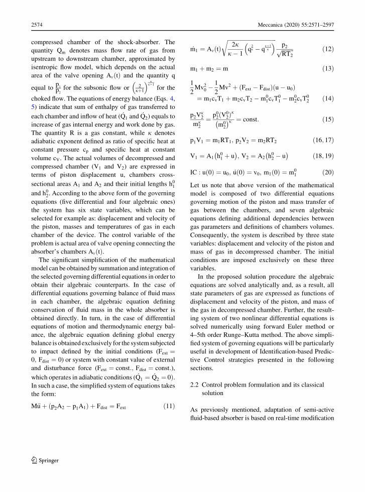
M€u þ p2A2 � p1A1ð Þ þ Fdist ¼ Fext ð11Þ
_m1 ¼ Av tð Þffiffiffiffiffiffiffiffiffiffiffiffiffiffiffiffiffiffiffiffiffiffiffiffiffiffiffiffiffiffiffiffiffiffiffi
2jj� 1
q2j � q
jþ1j
� �
r
p2ffiffiffiffiffiffiffiffiffi
RT2
p ð12Þ
m1 þ m2 ¼ m ð13Þ
1
2Mv2
0 �1
2Mv2 þ Fext � Fdistð Þ u � u0ð Þ
¼ m1cvT1 þ m2cvT2 � m01cvT0
1 � m02cvT0
2 ð14Þ
p2Vj2
mj2
¼ p02ðV0
2Þj
m02
� �j ¼ const: ð15Þ
p1V1 ¼ m1RT1; p2V2 ¼ m2RT2 ð16; 17Þ
V1 ¼ A1 h01 þ u
� �
; V2 ¼ A2 h02 � u
� �
ð18; 19Þ
IC : u 0ð Þ ¼ u0; _u 0ð Þ ¼ v0; m1 0ð Þ ¼ m01 ð20Þ
Let us note that above version of the mathematical
model is composed of two differential equations
governing motion of the piston and mass transfer of
gas between the chambers, and seven algebraic
equations defining additional dependencies between
gas parameters and definitions of chambers volumes.
Consequently, the system is described by three state
variables: displacement and velocity of the piston and
mass of gas in decompressed chamber. The initial
conditions are imposed exclusively on these three
variables.
In the proposed solution procedure the algebraic
equations are solved analytically and, as a result, all
state parameters of gas are expressed as functions of
displacement and velocity of the piston, and mass of
the gas in decompressed chamber. Further, the result-
ing system of two nonlinear differential equations is
solved numerically using forward Euler method or
4–5th order Runge–Kutta method. The above simpli-
fied system of governing equations will be particularly
useful in development of Identification-based Predic-
tive Control strategies presented in the following
sections.
2.2 Control problem formulation and its classical
solution
As previously mentioned, adaptation of semi-active
fluid-based absorber is based on real-time modification
123
2574 Meccanica (2020) 55:2571–2597
Page 5
of the valve opening and it is aimed at absorption and
dissipation of the entire impact energy with minimal
level of force generated on the impacting object and
minimal resulting value of its deceleration. Therefore,
the standard straightforward formulation of the optimal
impact absorption problem reads:
Find Av tð Þ jZ
u Tð Þ
u0
Fabsdu ¼ Eimp
and max Fabs � Fextð Þ is minimal
ð21Þ
subject to: model describing system dynamics defined
by Eqs. 1–10.
The variable T is the final time of the process when
the state of static equilibrium of the impacting object is
achieved (Fext ¼ Fdist ¼ 0; Fabs ¼ 0), while Fabs is the
total force generated by the absorber defined as a sum
of pneumatic and disturbance force: Fabs ¼ FpneuþFdist. Moreover, Eimp is the total energy to be
dissipated, being a sum of initial energy of the
impacting object and work done by the external force:
Eimp ¼ E0imp þ Eext
imp ¼ 1
2Mv2
0 þZ
u Tð Þ
u0
Fext du ð22Þ
where u Tð Þ� d and d is an assumed absorber’s stroke
d� h02. The alternative formulation of the optimal
impact absorption problem has the form of path-
tracking problem:
Find Av tð Þ jZ
u Tð Þ
u0
Fabs du ¼ Eimp
and
Z
T
t0
Fabs tð Þ � Foptabs
� �2dt is minimal
ð23Þ
where Foptabs is an optimal constant value of force
generated by the absorber and it results from total
amount of submitted energy Eimp and assumed
absorber’s stroke d:
Foptabs ¼
Mv20 þ 2
R d
u0Fextdu
2dð24Þ
The standard solution of impact mitigation problem is
based on three strict simplifying assumptions: i)
impacting object mass, its velocity and applied external
force are either known or identified at the beginning of
the process, ii) no disturbances (such as additional
unknown forces or fluid leakages) are present in the
system, iii) no constraints on maximal valve opening or
maximal speed of valve operation are considered (the
relevant values and changes of the gas mass flow rate
through the valve are provided). Under such assump-
tions the optimal control strategy is typically obtained
in two steps. The first step is solution of the path-finding
problem aimed at finding optimal feasible (realizable)
change of the absorber force Ffeasabs uð Þ:
Find Ffeasabs uð Þ
�
�
Z
u Tð Þ
u0
Ffeasabs du ¼ Eimp
and
Z
u Tð Þ
u0
Ffeasabs uð Þ � F
optabs
� �2du is minimal
ð25Þ
subject to: model describing system dynamics defined
by Eqs. 1–10.
The force Ffeasabs uð Þ is computed taking into account
that fluid is compressible and initial increase of force
cannot be immediate, but it requires utilization of at
least the part of absorber stroke. For the case of
double-chamber pneumatic shock-absorber the solu-
tion of the above path-finding problem includes three
distinct stages: (i) possibly fast increase of pneumatic
force with a closed valve, (ii) maintaining constant
value of pneumatic force, (iii) reduction of generated
force to zero to provide static equilibrium. Taking into
account the adiabatic equation of state for the gas of
constant mass (simplified version of Eq. 15) the above
three stages can be defined as:
Ffeasabs uð Þ ¼ A2p0
2
V02
V2 uð Þ
� j
�A1p01
V01
V1 uð Þ
� j
;
Ffeasabs uð Þ ¼ const:; Ffeas
abs uð Þ ! 0 ð26Þ
The second stage is based on the solution of the path-
tracking problem aimed at determination of variable
valve opening, which allows to follow previously
determined feasible force path:
Find Av jZ
T
0
Fabs Avð Þ � Ffeasabs
� �2dt is minimal ð27Þ
123
Meccanica (2020) 55:2571–2597 2575
Page 6
The above problem is often solved using the so-called
inverse dynamics approach, which assumes ideal
tracking of the feasible path and enables computation
of valve opening using the system of governing
equations (Eqs. 11–20) supplemented with the addi-
tional condition Fabs Avð Þ ¼ Ffeasabs . The solution of the
path-tracking problem can be defined: i) in terms of
displacement of the piston Av uð Þ—semi-passive or
semi-active control system [39], ii) directly in terms of
time Av tð Þ—open-loop control system, iii) in terms of
piston velocity Av vð Þ—feedback control system.
Eventually, the third stage assumes reduction of
absorber’s force to zero in order to obtain the state
of static equilibrium of the system and dissipation of
the entire impact energy. In the case when almost
entire admissible stroke is utilized and the valve
efficiency is large the third stage can be executed
infinitely fast. It includes immediate equalization of
pressures in both chambers and infinitesimal backward
motion of the piston. Three above stages obtained
within the classical AIA approach are visualized in
Fig. 3a and b, respectively.
The evident drawback of the classical AIA
approach is the fact that it requires either prior
knowledge of actual excitation, which is very rare in
most practical situations or its immediate identifica-
tion at the beginning of the process. Moreover, the
algorithm is characterized by the lack of robustness to
subsequent impact and system disturbances. Finally, it
will not operate properly in the case of active
constraints imposed on maximal valve opening or its
maximal operation speed. Most of these drawbacks are
eliminated by the proposed Identification-based Pre-
dictive Control algorithms, which will ensure adaptive
and robust performance of semi-active fluid-based
absorbers.
3 The concept and theory of self-adaptive systems
This section discusses the concept of self-adaptive
systems and derivation of the variational formulations
being the basis for development of the Identification-
based Predictive Control (IPC) systems. We focus on
the problem of impact mitigation, in which dynamic
excitation applied to the shock-absorber is defined by
impacting object mass and its initial velocity (M and
v0) or external force Fext tð Þ in the form of impulses of
relatively short duration.
The Identification-based Predictive Control algo-
rithms implemented in the absorbers allow for
obtaining high and robust performance and classify
them within the group of self-adaptive impact
absorbing systems, which do not require preliminary
knowledge about dynamic excitation and despite this
fact they are able to automatically adapt to actual
conditions and provide optimal dissipation of the
impact energy. Consequently, the absorbers equipped
with the IPC should meet strict requirements formu-
lated for self-adaptive systems and provide:
1. Automatic adaptation to unknown excitations
even if they repeat during the process.
2. Robustness to unknown disturbances, e.g., addi-
tional forces or sudden leakages of the fluid.
The above demands significantly complicate elab-
oration of relevant control strategy and cause that
application of the above described two stage proce-
dure, based on subsequent steps of path-finding and
path-tracking, cannot be directly applied.
(a) (b)
Fig. 3 Standard procedure applied for finding the optimal valve opening of the double-chamber shock-absorber: a the stage of path-
finding, b the stage of path-tracking
123
2576 Meccanica (2020) 55:2571–2597
Page 7
3.1 Mathematical formulations of optimal self-
adaptive impact mitigation problems
Mathematical formulation of the impact mitigation
problem referring to self-adaptive system is substan-
tially different than in the classical approach. The
derivation of the variational formulation of the control
problem for self-adaptive absorbers is based on
general principle of their operation, which includes
on-line adaptation by determination of the currently
optimal system path. The fundamental idea is that
initial conditions and entire time-history of excitation,
disturbances and control applied so far are reflected in
the actual system kinematics. Consequently, the
knowledge of actual system kinematics can be used
for determination of the optimal system path for the
further part of the process. Such approach allows to
determine actual optimal value of reaction force Foptabs
and corresponding value of acceleration aopt, which
should be maintained constant until the end of the
stroke in order to provide absorption of the entire
impact energy.
In particular, the force Foptabs can be computed by
integration of the equation of motion (Eq. 11) over
displacement from actual piston position u tð Þ to the
end of available stroke d, under assumption that force
generated by the absorber and external force remain
constant until the end of the process:
Z
d
u tð Þ
M€udu þZ
d
u tð Þ
Foptabsdu ¼
Z
d
u tð Þ
Fextdu ð28Þ
As a result, we obtain the actual optimal value of
absorber’s reaction force:
Foptabs tð Þ ¼ M€u tð Þ2
2 d � u tð Þð Þ þ Fext tð Þ ð29Þ
Using Eq. 11 once again, we obtain purely kinematic
condition, further called Kinematic Optimality Con-
dition (KOC), which defines actual optimal value of
acceleration:
aopt tð Þ ¼ � _u tð Þ2
2 d � u tð Þð Þ ð30Þ
The above conditions enable introducing two varia-
tional formulations of state-dependent path-tracking
problem: (i) the force-based formulation and (ii) the
kinematics-based formulation.
3.2 Force-based state-dependent path-tracking
General form of force-based state-dependent path-
tracking problem assumes minimization of the
squared difference between total force generated by
the absorber Fabs Av tð Þ; tð Þ and the actual optimal value
of force Foptabs tð Þ:
Find Av tð Þ jZ
u Tð Þ
u0
Fabsdu ¼ Eimp
and
Z
T
0
Fabs Av tð Þ; tð Þ � Foptabs tð Þ
� �2dt is minimal
ð31Þ
subject to: model describing system dynamics defined
by Eqs. 11–20.
The total absorber force generated by the absorber
is defined as:
Fabs Av tð Þ; tð Þ ¼ Fpneu Av tð Þð Þ þ Fdist tð Þ ð32Þ
while the actual optimal absorber force Foptabs is given by
Eq. 29. The above formulation substantially differs
from the classical path-tracking problem (Eq. 27) as
the second term depends on actual state of the system.
Since the absorber force Fabs depends on disturbance
force Fdist, while the optimal absorber force Foptabs
depends on external force Fext and both these forces
are assumed to be unknown, the direct solution of the
state-dependent path-tracking problem cannot be
found. However, by applying time-discretization the
above problem can be transformed into series of path-
tracking problems defined for time intervals ti;T �
,
while application of the model predictive control/
receding horizon control (MPC/RHC) enables short-
ening the control interval. Moreover, the actual
difference of unknown forces Fext and Fdist can be
calculated using impacting object’s equation of
motion at initial time instant of each control step.
Such approach leads to force-kinematics state-
123
Meccanica (2020) 55:2571–2597 2577
Page 8
dependent path-tracking problem, which is the basis
for the Hybrid Prediction Control method developed
in previous paper of the authors [36].
The additional comment concerns absorption and
dissipation of the impact energy. The optimal force
Foptabs tð Þ corresponds to absorption of the entire impact
energy so the condition of energy absorption is
fulfilled by reaching actual optimal path just before
the end of the process. Since in the considered
unconstrained problem the final part of the optimal
path can be always precisely tracked, the integral
condition of energy absorption will be always met and
it can be removed from problem formulation. In turn,
the condition of energy dissipation requires obtaining
the state of static equilibrium at assumed stroke d,
when impacting object is stopped. For the considered
purely pneumatic absorber with unequal areas of both
chambers such state can be obtained only when
d ! h02. In case d\h0
2 the problem formulation
defined by Eq. 31 has to be weakened and the
condition of energy dissipation has to be replaced by
the condition of energy absorption in which T denotes
time instant when v ¼ 0.
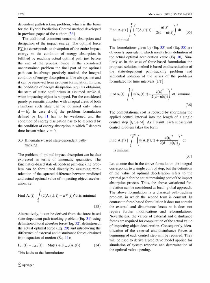
3.3 Kinematics-based state-dependent path-
tracking
The problem of optimal impact absorption can be also
expressed in terms of kinematic quantities. The
kinematics-based state-dependent path-tracking prob-
lem can be formulated directly by assuming mini-
mization of the squared difference between predicted
and actual optimal value of impacting object acceler-
ation, i.e.:
Find Av tð Þ jZ
T
0
€u Av tð Þ; tð Þ � aopt tð Þð Þ2dt is minimal
ð33Þ
Alternatively, it can be derived from the force-based
state-dependent path-tracking problem (Eq. 31) using
definition of total absorber force (Eq. 32), definition of
the actual optimal force (Eq. 29) and introducing the
difference of external and disturbance forces obtained
from equation of motion (Eq. 11):
Fext tð Þ � Fdist tð Þ ¼ M€u tð Þ þ Fpneu Av tð Þð Þ ð34Þ
This leads to the formulation:
Find Av tð Þ jZ
T
0
€u Av tð Þ; tð Þ þ _u tð Þ2
2 d � u tð Þð Þ
!2
dt
is minimal
ð35Þ
The formulations given by (Eq. 33) and (Eq. 35) are
obviously equivalent, which results from definition of
the actual optimal acceleration value (Eq. 30). Sim-
ilarly as in the case of force-based formulation the
proposed solution method is based on discretization of
the state-dependent path-tracking problem and
sequential solution of the series of the problems
formulated for time intervals ti;T �
:
Find Av tð Þ jZ
T
ti
€u Av tð Þ;tð Þþ _u tið Þ2
2 d�u tið Þð Þ
!2
dt isminimal
ð36Þ
The computational cost is reduced by shortening the
applied control interval into the length of a single
control step ti;tiþDt �
. As a result, each subsequent
control problem takes the form:
Find Av tð Þ jZ
tiþDt
ti
€u Av tð Þ; tð Þ þ _u tið Þ2
2 d � u tið Þð Þ
!2
dt
is minimal
ð37Þ
Let us note that in the above formulation the integral
corresponds to a single control step, but the definition
of the value of optimal deceleration refers to the
optimal path for the entire remaining part of the impact
absorption process. Thus, the above variational for-
mulation can be considered as local–global approach.
The above formulation is a classical path-tracking
problem, in which the second term is constant. In
contrast to force-based formulation it does not contain
the external and disturbance forces so it does not
require further modifications and reformulations.
Nevertheless, the values of external and disturbance
forces are required for computation of the actual value
of impacting object deceleration. Consequently, iden-
tification of the external and disturbance forces at
beginning of each control step will be required. They
will be used to derive a predictive model applied for
simulation of system response and determination of
the optimal valve opening.
123
2578 Meccanica (2020) 55:2571–2597
Page 9
3.4 Identification-based predictive control
In the further part of the paper three different
implementations of the Identification-based Predictive
Control (IPC) are discussed. Their development is
focused on more precise control of valve opening and
more accurate tracking of the optimal system path than
achieved by previously developed methods such as the
Hybrid Prediction Control [36]. In particular, they
should ensure correct operation of the shock-absorber
when initial deceleration is close to the optimal one.
This objective is achieved by identification of the
difference of external and disturbance force at the
beginning of each control step by recalling the
equation of impacting object motion (Eq. 11) at time
instant ti, which yields:
Fext tið Þ � Fdist tið Þ ¼ M€u tið Þ þ Fpneu tið Þ ð38Þ
Identified force difference is assumed to remain
constant during the entire control step and to change
at the subsequent control steps of the process.
Conducted identification enables development of the
predictive model, which is implemented in the con-
troller in order to simulate and optimize system
response at a single control step. Such model is
obtained from simplified model of the system defined
by Eqs. 11-20 by assuming Fext tð Þ � Fdist tð Þ ¼Fext tið Þ � Fdist tið Þ and by substituting Eq. 38. This
leads to specific forms of the equation of motion
(Eq. 39) and equation of global energy balance
(Eq. 42). The system of equations for a single control
step takes the form:
M €u� €u tið Þð Þþ p2�p2 tið Þð ÞA2� p1�p1 tið Þð ÞA1¼0 ð39Þ
_m1 ¼ Av tð Þffiffiffiffiffiffiffiffiffiffiffiffiffiffiffiffiffiffiffiffiffiffiffiffiffiffiffiffiffiffiffiffiffiffiffi
2jj� 1
q2j � q
jþ1j
� �
r
p2ffiffiffiffiffiffiffiffiffi
RT2
p ð40Þ
m1 þ m2 ¼ m ð41Þ
1
2Mv tið Þ2� 1
2Mv2
þ M€u tið Þ þ p2 tið ÞA2 � p1 tið ÞA1ð Þ½ � u � u tið Þð Þ
¼ p1V1
j� 1þ p2V2
j� 1� p1 tið ÞV1 tið Þ
j� 1� p2 tið ÞV2 tið Þ
j� 1
ð42Þ
p2Vj2
mj2
¼ p2 tið ÞV2 tið Þj
m2 tið Þj ð43Þ
IC : u tið Þ ¼ u0; _u tið Þ ¼ v0; m1 tið Þ ¼ m01 ð44Þ
and it is complemented by equation of state of gas in
both chambers (Eqs. 16, 17) and definitions of cham-
bers volumes (Eqs. 18, 19). The above predictive
model contains incremental equation of motion, which
includes differences between actual acceleration and
pressure values, and the values at the beginning of the
control step. Moreover, it contains specific form of the
energy balance equation.
The predictive model is used in three different
manners:
• for simulation of the system response for arbitrarily
assumed change of valve opening: Straightforward
Dynamics Prediction (SDP),
• for computation of the valve opening correspond-
ing to assumed kinematics of the system: Inverse
Dynamics Prediction (IDP) and its generalization
(GIDP).
• for computation of the optimal value of constant
valve opening: Sub-Optimal Dynamics Prediction
(SODP).
The proposed implementations of the IPC are
reflected by the following control strategies:
1. Optimal control strategy: pneumatic force and
impacting object deceleration provide minimiza-
tion of the path-tracking error by exact solution of
the variational problem, which is found in the
class of valve openings changed continuously at
single control step.
2. Control strategy with constant valve opening:
pneumatic force and impacting object decelera-
tion ensure minimal value of the path-tracking
error by the solution found in the class of constant
valve openings at a single control step.
3. Control strategy with assumed kinematics: pneu-
matic force and impacting object deceleration
ensure minimal value of path-tracking error by the
solution found in the class of assumed functions
describing change of deceleration within a control
step.
The optimization problems which are solved after
identification of the system and excitation parameters
are summarized in Table 1. All these alternatives of
123
Meccanica (2020) 55:2571–2597 2579
Page 10
the Identification-based Predictive Control are derived
in the following sections.
4 Identification-based Predictive Control: optimal
control strategy
The optimal control strategy is aimed at finding exact
unconstrained solution of the kinematics-based path-
tracking (Eq. 37) formulated at a single control step.
The solution assumes continuous change of valve
opening in the considered time period ½ti; ti þ Dt�.
4.1 Theoretical solution at a single control step
The objective of the formulated control problem is to
find continuous function defining change of valve
opening which minimizes path-tracking error:
Find Aoptv tð Þ¼argmin
Z
tiþDt
ti
€u Av tð Þ;tð Þþ _u tið Þ2
2 d�u tið Þð Þ
!2
dt
ð45Þ
Although finding constrained solution of the above
problem requires methods of variational calculus, the
unconstrained solutions can be easily found in intu-
itive manner. Theoretical solution, which does not
take into account constitutive equation of the fluid,
results from comparing the integrand of Eq. 45 to zero
and reads:
€uopt Av tð Þ; tð Þ ¼ � _u tið Þ2
2 d � u tið Þð Þ ð46Þ
Thus, at a single control step the impacting object
deceleration should remain constant and equal to
optimal value calculated at the initial time instant.
Between the control steps it should suffer a jump,
whose direction depends on the sign of the difference
between the actually optimal and actual value of
deceleration. In the case of pneumatic absorber, the
sudden change of impacting object’s deceleration to
the optimal value is impossible due to physical
properties of the medium and limitation of maximal
opening of the valve. The optimal change of piston
deceleration can be deduced using the Eq. 46, which
implies that:
• it should remain constant, €u Av tð Þ; tð Þ ¼ €u tið Þ,• it should increase at maximal rate (valve fully
closed) and after possible reaching of the optimal
level should remain constant,
• it should decrease at maximal rate (valve fully
open), and after possible reaching of the optimal
level should remain constant,
in the cases of actual value of deceleration being equal,
smaller and larger than the optimal one, respectivelly.
Let us notice that in the first case the required valve
opening Av tð Þ will not be constant but it will
continuously change over time. In the non-degener-
ated second and third case, the optimal value of
deceleration might be reached or not during a single
control step depending on the actual state of the
system. The optimal changes of deceleration corre-
sponding to two possible non-trivial cases are pre-
sented graphically in Fig. 4a and b, respectively.
4.2 The control strategy
The optimal two-stage control strategy includes three
subsequent steps:
1. The identification step: identification of the
difference of external and disturbance force in
order to obtain predictive model of the system for
the considered control step.
Table 1 Summary of optimization problems solved within different implementations of the IPC
Optimal control strategyFind Aopt
v tð Þ ¼ arg minR tiþDt
tiu::
Av tð Þ; tð Þ þ u:
tið Þ2
2 d�u tið Þð Þ
� 2
dt
Control strategy with constant valve openingFind Aopt
v ¼ arg minR tiþDt
tiu::
Aconst:v ; t
� �
þ u:
tið Þ2
2 d�u tið Þð Þ
� 2
dt
Control strategy with assumed kinematicsFind bopt ¼ arg min
R
tiþDt
ti
u::b; tð Þ þ u
:tið Þ2
2 d�u tið Þð Þ
� 2
dt
where b - vector of coefficients defining function €u tð Þ at the control step Dt
123
2580 Meccanica (2020) 55:2571–2597
Page 11
2. The prediction step: application of the SDP to
simulate the system response with fully open or
closed valve and check whether the optimal value
of deceleration is reached within the actual control
step.
3. The control determination step: application of the
IDP to compute change of valve opening during
the second part of the control step when deceler-
ation remains constant.
The identification step starts with identification of
the difference of external and disturbance force at each
subsequent control step and it is based on Eq. 38.
Determined difference of external and disturbance
forces is used to obtain specific forms of the equation
of motion and equation of global energy balance used
in the predictive model, which is applied in both the
prediction step and the control determination step.
The prediction step follows the first stage of
theoretical solution of the variational problem formu-
lated for a single control step (Sect. 4.1). The predic-
tive model is applied to conduct the Straightforward
Dynamics Prediction (SDP) and simulate response of
the system with fully closed or fully open valve. The
SDP procedure utilizes system of equations governing
absorber response at a single control step (Eqs. 39–
44), which includes the valve flow equation assuming
minimal or maximal valve opening:
Av tð Þ ¼ Aminv for €u tið Þ[ aopt tið Þ
Amaxv for €u tið Þ\aopt tið Þ
�
ð47Þ
The simulation of the system response is conducted for
the first part of the control step, i.e. until the time
instant when predicted deceleration reaches optimal
value defined by the r.h.s. of Eq. 46.
The control determination step starts when piston
deceleration achieves optimal value and it is con-
ducted until the end of the control step. The predictive
model is applied to perform the Inverse Dynamics
Prediction (IDP) and compute change of valve open-
ing Av tð Þ which provides constant deceleration of the
impacting object during the second part of the control
step. The IDP procedure assumes constant value of the
difference of external and disturbance force and it is
conducted using the same predictive model as the SDP
procedure applied during prediction step. However, in
the IDP the valve opening is considered as time
dependent unknown, while the system of governing
equations is enriched by the definition of system
kinematics resulting from the condition of piston
deceleration being constant:
€uopt ¼ €u tcci
� �
ð48aÞ
vopt ¼ €u tcci
� �
t � tcci
� �
þ v tcci
� �
ð48bÞ
uopt ¼ 1
2€u tcc
i
� �
t � tcci
� �2þv tcci
� �
t � tcci
� �
þ u tcci
� �
ð48cÞ
where tcci denotes the end of the first part of the control
step (time of control change). The above kinematic
relations allow to determine changes of chambers
volumes (Vopt1 and V
opt2 ) during the second stage of the
process. As a result, selected equations of the predic-
tive model (Eqs. 39, 41, 42, 43) can be rewritten as a
system of algebraic equations:
p2A2 � p1A1 ¼ p2 tcci
� �
A2 � p1 tcci
� �
A1 ð49Þ
m1 þ m2 ¼ m ð50Þ
ðp2ðtcci ÞA2 � p1ðtcc
i ÞA1ÞðuoptðtÞ � uðtcci ÞÞ
¼ p1Vopt1
j� 1þ p2V
opt2
j� 1� p1ðtcc
i ÞV1ðtcci Þ
j� 1� p2ðtcc
i ÞV2ðtcci Þ
j� 1
ð51Þ
(a) (b)
Fig. 4 Optimal change of
deceleration during a single
control step: a the case of
too low value of initial
deceleration, b the case of
too high value of initial
deceleration
123
Meccanica (2020) 55:2571–2597 2581
Page 12
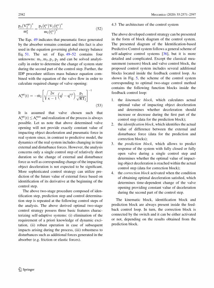
p2 Vopt2
� �j
mj2
¼p2 tcc
i
� �
V2 tcci
� �j
m2 tcci
� �j ð52Þ
The Eqs. 49 indicates that pneumatic force generated
by the absorber remains constant and this fact is also
used in the equation governing global energy balance
Eq. 51. The set of Eqs. 49–52 contains four
unknowns: m1;m2; p1; p2 and can be solved analyti-
cally in order to determine the change of system state
during the second part of the control step. Further, the
IDP procedure utilizes mass balance equation com-
bined with the equation of the valve flow in order to
calculate required change of valve opening:
Aoptv tð Þ ¼ � _m2
ffiffiffiffiffiffiffiffiffiffiffiffiffiffiffiffiffiffiffiffiffiffiffiffiffiffiffiffiffiffiffiffiffiffiffi
2jj� 1
q2j � q
jþ1j
� �
r
p2ffiffiffiffiffiffiffiffiffi
RT2
p" #�1
ð53Þ
It is assumed that valve chosen such that
Aoptv tð Þ�Amax
v and realization of the process is always
possible. Let us note that above determined valve
opening will not provide exactly constant value of
impacting object deceleration and pneumatic force in
real system since, in contrast to predictive model, the
dynamics of the real system includes changing in time
external and disturbance forces. However, the analysis
concerns only a single control step of relatively short
duration so the change of external and disturbance
force as well as corresponding change of the impacting
object deceleration is not expected to be significant.
More sophisticated control strategy can utilize pre-
diction of the future value of external force based on
identification of its derivative at the beginning of the
control step.
The above two-stage procedure composed of iden-
tification step, prediction step and control determina-
tion step is repeated at the following control steps of
the analysis. The above derived optimal two-stage
control strategy possess three basic features charac-
terizing self-adaptive systems: (i) elimination of the
requirement of a priori knowledge of dynamic exci-
tation, (ii) robust operation in case of subsequent
impacts arising during the process, (iii) robustness to
disturbances such as additional forces generated in the
absorber (e.g. friction or elastic forces).
4.3 The architecture of the control system
The above developed control strategy can be presented
in the form of block diagram of the control system.
The presented diagram of the Identification-based
Predictive Control system follows a general scheme of
self-adaptive control systems [36], but it is more
detailed and complicated. Except the classical mea-
surement (sensors) block and valve control block, the
proposed control system includes several additional
blocks located inside the feedback control loop. As
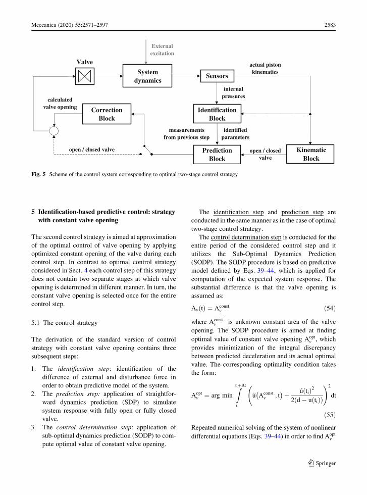
shown in Fig. 5, the scheme of the control system
corresponding to optimal two-stage control method
contains the following function blocks inside the
feedback control loop:
1. the kinematic block, which calculates actual
optimal value of impacting object deceleration
and determines whether deceleration should
increase or decrease during the first part of the
control step (data for the prediction block);
2. the identification block, which identifies the actual
value of difference between the external and
disturbance force (data for the prediction and
correction blocks);
3. the prediction block, which allows to predict
response of the system with fully closed or fully
open valve during a single control step and
determines whether the optimal value of impact-
ing object deceleration is reached within the actual
control step (data for correction block);
4. the correction block activated when the condition
of obtaining optimal deceleration satisfied, which
determines time-dependent change of the valve
opening providing constant value of deceleration
during the second part of the control step.
The kinematic block, identification block and
prediction block are always present inside the feed-
back control loop. In turn, the correction block is
connected by the switch and it can be either activated
or not, depending on the results obtained from the
prediction block.
123
2582 Meccanica (2020) 55:2571–2597
Page 13
5 Identification-based predictive control: strategy
with constant valve opening
The second control strategy is aimed at approximation
of the optimal control of valve opening by applying
optimized constant opening of the valve during each
control step. In contrast to optimal control strategy
considered in Sect. 4 each control step of this strategy
does not contain two separate stages at which valve
opening is determined in different manner. In turn, the
constant valve opening is selected once for the entire
control step.
5.1 The control strategy
The derivation of the standard version of control
strategy with constant valve opening contains three
subsequent steps:
1. The identification step: identification of the
difference of external and disturbance force in
order to obtain predictive model of the system.
2. The prediction step: application of straightfor-
ward dynamics prediction (SDP) to simulate
system response with fully open or fully closed
valve.
3. The control determination step: application of
sub-optimal dynamics prediction (SODP) to com-
pute optimal value of constant valve opening.
The identification step and prediction step are
conducted in the same manner as in the case of optimal
two-stage control strategy.
The control determination step is conducted for the
entire period of the considered control step and it
utilizes the Sub-Optimal Dynamics Prediction
(SODP). The SODP procedure is based on predictive
model defined by Eqs. 39–44, which is applied for
computation of the expected system response. The
substantial difference is that the valve opening is
assumed as:
Av tð Þ ¼ Aconst:v ð54Þ
where Aconst:v is unknown constant area of the valve
opening. The SODP procedure is aimed at finding
optimal value of constant valve opening Aoptv , which
provides minimization of the integral discrepancy
between predicted deceleration and its actual optimal
value. The corresponding optimality condition takes
the form:
Aoptv ¼ arg min
Z
tiþDt
ti
€u Aconst:v ; t
� �
þ _u tið Þ2
2 d � u tið Þð Þ
!2
dt
ð55Þ
Repeated numerical solving of the system of nonlinear
differential equations (Eqs. 39–44) in order to find Aoptv
Fig. 5 Scheme of the control system corresponding to optimal two-stage control strategy
123
Meccanica (2020) 55:2571–2597 2583
Page 14
satisfying condition given by Eq. 55 is computation-
ally relatively expensive, so simplification and speed
up of the entire procedure is recommended in practical
applications. This can be achieved by: (i) proper
choice of the initial value of constant valve opening
for the optimization procedure, (ii) simplified solution
of the governing equations (Eqs. 39–44) based on
linearization of the response at a single control step.
The initial value of constant valve opening for the
optimization procedure can be determined using the
inverse dynamics approach, which enables computa-
tion of the valve opening providing constant deceler-
ation of the impacting object during a single control
step, cf. Eqs. 49–52. Such initial value can be assumed
either as initial or average value of optimal time-
dependent valve opening determined from IDP:
Ainiv tið Þ ¼ Aopt
v tið Þ or
Ainiv tið Þ ¼ 1
2½Aopt
v tið Þ þ Aoptv ti þ Dtð Þ�
ð56Þ
where Aoptv tið Þ and Aopt
v ti þ Dtð Þ can be determined
from Eq. 53. Since the definite integral defined by
Eq. 55 is convex in terms of constant valve opening
and the initial point is correctly chosen, the optimiza-
tion problem can be solved using standard gradient-
based methods and converges fast.
The second approach assumes standard linearization
of the Eqs. 39–44 at a single control step with respect to
selected state variables and analytical solution of the
system of linearized differential equations for constant
valve opening. Alternatively, the original system of
differential equations governing the problem can be
solved using forward Euler method with only one step of
integration applied at each control step ti; ti þ Dt½ �. Both
above methods result in analytical formula defining
the value of impacting object deceleration in terms of
system state at the beginning of the control step,
applied constant valve opening Aconst:v and time of the
process:
€u Aconst:v ; t
� �
¼ f p1 tið Þ; p2 tið Þ;m1 tið Þ;m2 tið Þ; u tið Þ;ðv tið Þ; a tið Þ;Aconst:
v ; t�
ð57Þ
where f indicates known analytical function. Provid-
ing that the version of thermodynamic energy balance
equations is properly chosen, the formula defining
change of acceleration in a single step is relatively
simple and can be integrated analytically in time to
obtain definite integral of the r.h.s. of Eq. 55 in the
form of analytical formula I ¼ I Aconst:v
� �
: This allows
to simplify the original optimization problem to the
simple problem:
Aoptv ¼ arg min I Aconst:
v
� �
ð58Þ
which can be solved using standard minimization
conditions involving zero value of the first and
positive value of the second derivative with respect
to Aconst:v .
5.2 Alternative version of control strategy
with constant valve opening
The above introduced control strategy with constant
valve opening can be superseded by its alternative
version, in which the prediction steps are entirely
eliminated. The alternative version of control strategy
with constant valve opening involves the following steps:
1. The identification step identification of the differ-
ence of external and disturbance force.
2. The control determination step using the SODP in
order to determine the optimal constant valve
opening for each control step using predictive
model of the system.
In fact, in the standard version of the control strategy
with constant valve opening the presence of the
prediction steps was aimed at identifying the control
steps at which specific non-extreme constant value of
valve opening does not have to be calculated and
control determination step does not have to be
executed. Such approach was justified because the
standard SDP procedure applied in prediction step
requires only straightforward simulation of the system
response, while SODP procedure applied in control
determination step requires solution of the inverse
problem. The control determination steps were asso-
ciated with higher numerical cost than prediction steps
and their elimination allowed for reducing the global
computational cost.
However, linearization of the predictive model
results in analytical formula defining change of
acceleration at a single control step (Eq. 57) and
possibility of finding optimal Aoptv in a single iteration
123
2584 Meccanica (2020) 55:2571–2597
Page 15
(Eq. 58). Thus, the numerical cost of the control
determination step is significantly reduced and it is
similar to the cost of the prediction step. Conse-
quently, the prediction steps can be replaced by
control determination steps without significant
increase of total computational cost. Such approach
allows for simplification and unification of the entire
control procedure. On the other hand, its disadvantage
is that decision about application of fully closed or
opened valve is burdened with an error resulting from
linearization of the predictive model.
The above derived two versions of the control
strategy with constant valve opening possess the basic
features of the optimal two-stage strategy, including
elimination of the requirement of a priori knowledge
of dynamic excitation, robust operation in case of
subsequent impacts and robustness to disturbances. As
a result of the application of the SOPD assuming
constant valve opening, the single-stage methods are
expected to lead to slightly worse solution of the
original variational problem than optimal two-stage
methods. However, the single-stage methods are
expected to require less intensive control actions with
globally more smooth change of valve opening and
only small jumps between the control steps.
5.3 Architecture of the control system
The scheme of the control system corresponding to
control strategy with constant valve opening in its
standard version (with prediction and control deter-
mination steps) is identical as the scheme of the
control system corresponding to optimal two-stage
method, presented in Fig. 5. The main difference
between these two control systems is different
realization of the correction block (SODP vs. IDP)
and different time period for which the correction is
introduced (the entire period of the control step vs. the
second part of control step).
In contrast, the scheme of the control system
corresponding to alternative version (without predic-
tion step) includes the following control blocks inside
the feedback control loop (Fig. 6):
1. the kinematic block, which calculates actual
optimal value of impacting object deceleration
(data for valve opening computation block);
2. the identification block, which determines the
actual value of difference between the external
and disturbance force (data for valve opening
computation block);
3. the valve opening computation block, which
determines constant valve opening providing
minimal deviation of deceleration from the opti-
mal value at considered control step.
Let us note that all above blocks are always present
in the discussed version of the system and in contrast
to the system presented in Fig. 5 the switched
connection between two final blocks of the system
does not appear.
6 Identification-based predictive control: control
strategy with assumed kinematics
The last developed control method is aimed at
approximation of the optimal two-stage control strat-
egy by assuming arbitrary kinematics of the impacting
object at each control step. The method combines the
advantages of previously developed approaches:
employment of the IDP introduced within the optimal
two-stage strategy and elimination of prediction step
as in the strategy with constant valve opening.
6.1 The control strategy
Derivation of the control strategy with assumed
kinematics includes two subsequent steps:
1. The identification step: identification of the
difference of external and disturbance force in
order to obtain predictive model of the system at
considered control step.
2. The control determination step: assumption of the
arbitrary function describing the change of accel-
eration at a single control step, optimization its
parameters using kinematics-based formulation
and determination of the corresponding change of
valve opening using IDP.
The key concept of the current version of the
control determination step is assumption of the
arbitrary type of function €u b; tð Þ defining change of
impacting object’s deceleration during a single control
123
Meccanica (2020) 55:2571–2597 2585
Page 16
step, where b is the vector of unknown parameters
calculated for actual time step. The optimization
procedure is aimed at finding values of parameters
which provide minimization of the integral discrep-
ancy between assumed deceleration and its actual
optimal value. The corresponding optimality condi-
tion takes the form:
bopt ¼ arg min
Z
tiþDt
ti
u::b; tð Þ þ u
:tið Þ2
2 d � u tið Þð Þ
!2
dt
ð59Þ
In the second step, the determined deceleration path at
a single control step is tracked using time-dependent
change of the valve opening, which is computed using
the predictive model of the system. Since a wide class
of functions describing change of impacting object’s
deceleration can be assumed (e.g. linear, quadratic or
exponential) the method yields a large class of
solutions of the considered control problem.
In the simplest version of the method, deceleration
of the impacting object is assumed to change linearly
between the actual and the final value. Assumption of
the continuity of deceleration at the initial time instant
allows to define linear function describing change of
deceleration in terms of only one unknown parameter
being the value of acceleration at the end of the control
step b ¼ €u ti þ Dtð Þ:
€u b; tð Þ ¼ €u tið Þ þ b� €u tið ÞDt
t � tið Þ ð60Þ
In such case the optimization problem takes the form:
€uopt tiþDtð Þ¼arg min
Z
tiþDt
ti
€u tið Þþb� €u tið ÞDt
t� tið Þ�
þ _u tið Þ2
2 d�u tið Þð Þ
!2
dt
ð61Þ
The above problem is convex and the solution can be
obtained from standard differential conditions involv-
ing zero value of the first derivative and positive value
of the second derivative with respect to b. The solution
reads:
bopt ¼ €uopt ti þ Dtð Þ ¼ � €u tið Þ2
þ 3
4
_u tið Þ2
d � u tið Þð Þ ð62Þ
and indicates that discrepancy of impacting object’s
deceleration from the optimal value changes sign and
its value decreases twice at each control step. This
causes that actual deceleration is shifted towards the
optimal deceleration determined at the end of each
control step, and improves convergence of the entire
process (indicated by zero value of integrand in
Eq. 61). The knowledge of initial conditions at the
beginning of the control step and the optimal final
Fig. 6 Scheme of the control system corresponding to control strategy with constant valve opening
123
2586 Meccanica (2020) 55:2571–2597
Page 17
value of deceleration allows to determine the desired
change of deceleration, velocity and displacement of
the impacting object during the control step:
€uopt ¼ €u tið Þ þ €uopt ti þ Dtð Þ � €u tið ÞDt
t � tið Þ ð63Þ
vopt ¼ 1
2
€uopt ti þ Dtð Þ � €u tið ÞDt
t � tið Þ2þ€u tið Þ t � tið Þþ v tið Þ
ð64Þ
uopt ¼ 1
6
€uopt ti þ Dtð Þ � €u tið ÞDt
t � tið Þ3þ 1
2€u tið Þ t � tið Þ2
þ v tið Þ t � tið Þ þ u tið Þð65Þ
as well as the corresponding changes of chambers
volumes (Vopt1 and V
opt2 ). The full knowledge of the
system kinematics allows to apply the concept of
Generalized Inverse Dynamics Prediction and com-
pute valve opening corresponding to non-constant
impacting object deceleration. The system of equa-
tions used to determine change of thermodynamic
parameters of gas is obtained by substitution of
derived optimal kinematics into the predictive model
of the system and reads:
p2A2 � p1A1 ¼ p2 tið ÞA2 � p1 tið ÞA1 � M½€uopt � €u tið Þ�ð66Þ
m1 þ m2 ¼ m ð67Þ
1
2Mv tið Þ2� 1
2MðvoptÞ2
þ M€u tið Þ þ p2 tið ÞA2 � p1 tið ÞA1ð Þ½ � uopt � u tið Þð Þ
¼ p1Vopt1
j� 1þ p2V
opt2
j� 1� p1 tið ÞV1 tið Þ
j� 1
� p2 tið ÞV2 tið Þj� 1
ð68Þ
p2 Vopt2
� �j
mj2
¼p2 tcc
i
� �
V2 tcci
� �j
m2 tcci
� �j ð69Þ
The above system of algebraic equations describing
GIDP has substantially different form than the corre-
sponding system of equations describing standard
IDP, which is used for maintaining constant value of
deceleration (Eqs. 49–52). In particular, the equation
describing change of pneumatic force includes addi-
tional term depending on the impacting object mass
and its optimal deceleration, cf. the r.h.s. of Eqs. 49
and 66. Moreover, in equation of global energy
balance the work done on gas by external forces is
expressed in terms of impacting object mass and its
optimal velocity, cf. the l.h.s. of Eqs. 51 and 68.
Although equations governing the GIDP are relatively
complicated, the change of thermodynamic parame-
ters of the fluid can be determined analytically.
Further, the corresponding change of valve opening
during the considered control step is calculated using
valve flow equation (Eq. 53). The above described
procedure, which is based on identification step and
control determination step, is repeated for the subse-
quent control steps of the impact absorption process.
The above derived control method with assumed
kinematics possess basic features of the optimal two-
stage methods including the lack of requirement of a
priori knowledge of dynamic excitation, robust oper-
ation in the case of subsequent impacts and distur-
bances. As a result of the assumption of non-optimal,
e.g. linear change of impacting object deceleration, the
method is expected to lead to slightly worse solution of
the original variational problem than optimal two-
stage method, but similar as the single-stage method
with constant valve opening.
The single-stage method with assumed kinematics
is expected to require control actions of comparable
intensity as previously developed single-stage control
methods with constant valve opening. Nevertheless, it
will require continuous and smooth change of valve
opening with modifications during a single control
step, but without small jumps between the steps.
Moreover, due to application of the IDP the numerical
cost of the method is also expected to be comparable
with the cost of the method with constant valve
opening based on linearized predictive model. In
general, the difference between the control strategy
with constant valve opening and the control strategy
with assumed kinematics is expected to be very subtle.
6.2 Architecture of the control system
The scheme of the control system corresponding to the
control strategy with assumed kinematics is similar to
previously introduced control scheme developed for
the alternative version of the control strategy with
123
Meccanica (2020) 55:2571–2597 2587
Page 18
constant valve opening (Fig. 6). It includes the
following blocks inside the feedback control loop:
1. the kinematic block, which calculates actual
optimal value of impacting object deceleration
and assumes function describing the change of
deceleration during the entire control step (data for
valve opening computation block);
2. the identification block, which identifies either the
actual value of difference between the external
and disturbance force (data for valve opening
computation block);
3. the valve opening computation block, which
determines system kinematics ensuring minimal
discrepancy of deceleration from the optimal
value at considered control step and the corre-
sponding valve opening.
Similarly as in the previous control scheme, all
above mentioned blocks are always present and the
connection by switch does not appear. The only
difference in comparison to control scheme for con-
stant valve opening is that the output from kinematic
block is not only the information concerning actual
optimal value of deceleration but also assumed
function describing change of acceleration.
7 Numerical study on performance
of the identification-based predictive controllers
The numerical verification of the operation of the
developed Identification-based Predictive Control
algorithms is conducted using double-chamber pneu-
matic shock-absorber under impact excitation caused
by impact of a rigid object. The values of external and
disturbance forces are assumed to be unknown. For the
ease of comparisons, the dimensions of the shock-
absorber, initial parameters of gas and parameters of
the impact excitation are the same as in most of the
examples discussed in previous papers of the authors
(Table 2). In order to conduct clear analyses of system
robustness two types of disturbances are considered:
(i) linearly increasing elastic force with stiffness
coefficient k ¼ 2000 N=m, (ii) linearly decreasing
viscous force with damping coefficient c ¼ 40 Ns=m,
both acting at the entire stroke of the absorber.
Separate simulations are conducted for three imple-
mentations of the IPC:
• Optimal two-stage control strategy,
• Strategy with constant valve opening,
• Control strategy with assumed kinematics.
The operation of all three systems is assessed under
disturbance caused by elastic and viscous forces. The
methods are thoroughly compared against each other
in terms of efficiency and required control actions.
7.1 Optimal control strategy
The optimal two-stage control strategy was initially
tested using impact excitation and unknown elastic
disturbance force. The control strategy includes two
distinct stages of valve control. In the first stage of the
process the valve remains closed in order to obtain
possibly fast increase of force generated by the
absorber, up to the level required for dissipation of
the entire impact energy. In the second stage of the
process the intensive control actions with fast changes
of valve opening are performed (Fig. 7a) in order to
maintain approximately constant level of total force
generated by the shock-absorber until the end of the
stroke (Fig. 7b). During the first part of each control
step the valve is fully opened in order to compensate
the increase of total generated force caused by the
increase of elastic disturbance force. In turn, during
the second part of each control step the valve opening
Table 2 Parameters of the shock-absorber, the gas state, the impact loading and the disturbance assumed in presented numerical
examples
M
[kg]
v0
[m/s]
Gas R
[J/kg/K]p0
1; p02
[kPa]
T01;T
02
[K]
V01
[cm3]
V02
[cm3]
h01
[mm]
h02
[mm]
5 5 air 287.69 300 293.15 7.54 118.12 6 94
123
2588 Meccanica (2020) 55:2571–2597
Page 19
changes in time in order to maintain exactly constant
value of force calculated using predictive model and
approximately constant value of force in the real
system. The optimal change of valve opening calcu-
lated during the second part of each control step
creates the characteristic time-history of continuous
phases of valve opening with the initial increase and
gradual decease almost to zero value at the end of the
process.
Let us note that at certain time instant of the process
the valve is commutatively opened and closed at the
consecutive control steps, which can be considered as
sudden increase of the required control effort. This
phenomenon is related to finite lengths of the time steps
used in applied numerical integration procedure and the
lengths of time periods when the valve opening has to
remain extreme. The detailed explanation is as follows.
At each consecutive control step the initial time period
when the valve remains fully open gradually decreases
due to reduction of piston velocity and corresponding
reduction of pneumatic force increase, which is driven
by change of chambers’ volumes. Eventually, it drops
below the length of the applied time integration step.
Since the condition for finishing the initial stage of
maximal valve opening is checked at the end of the time
step the valve remains open for excessive amount of
time, which results in drop of pneumatic force below
the optimal level. Further, the non-optimal level of
pneumatic force is maintained constant, but this effect
is compensated by gradual increase of elastic distur-
bance force. As a result, at the end of the control step the
total value of generated force is larger than the optimal
one and at the valve is again fully opened at the
beginning of the next control step. However, the effect
of elastic force increase diminishes as the process of
impact absorption proceeds due to decreasing velocity
of the piston. Eventually, the optimal value of impact-
ing object deceleration is not achieved until the end of
the control step. As a result, the next control step
commences with the stage when the valve is fully
closed. The above effect of sudden increase of the
control effort is also expected to appear in practical
realization of the control system due to finite length of
minimal time of valve opening.
The optimal two-stage control strategy was also
investigated using in the case of unknown viscous
disturbance force. Similarly as in the case of distur-
bance caused by elastic force the strategy includes the
initial stage when the valve is closed and generated
force increases at maximal rate and the stage when
valve control provides approximately constant level of
generated force (Fig. 8a, b). The first stage is charac-
terized by substantially different shape of force–
displacement curve and duration due to large influence
of the viscous force at the beginning of the process.
Consequently, the second stage of the process is
characterized by lower level of total force generated
by the absorber. Moreover, in contrast to the case of
elastic force disturbance, during the second stage of
the process at the first part of each control step the
valve is repeatedly fully closed in order to compensate
the decrease of viscous disturbance force. The sudden
increase of the control effort, which appears at certain
part of the process is revealed by commutative full
closing and opening of the valve at the beginning of
the subsequent control steps. Analogously as previ-
ously, this phenomenon is caused by too long period
when the valve remains closed, too large increase of
the pneumatic force at the beginning of the control
(a) (b)
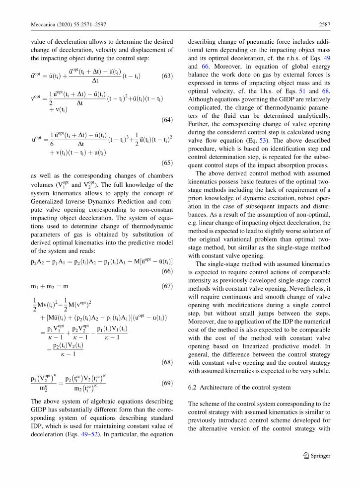
Fig. 7 Optimal two-stage control strategy, disturbance introduced by the elastic force: a change of valve opening area, b change of
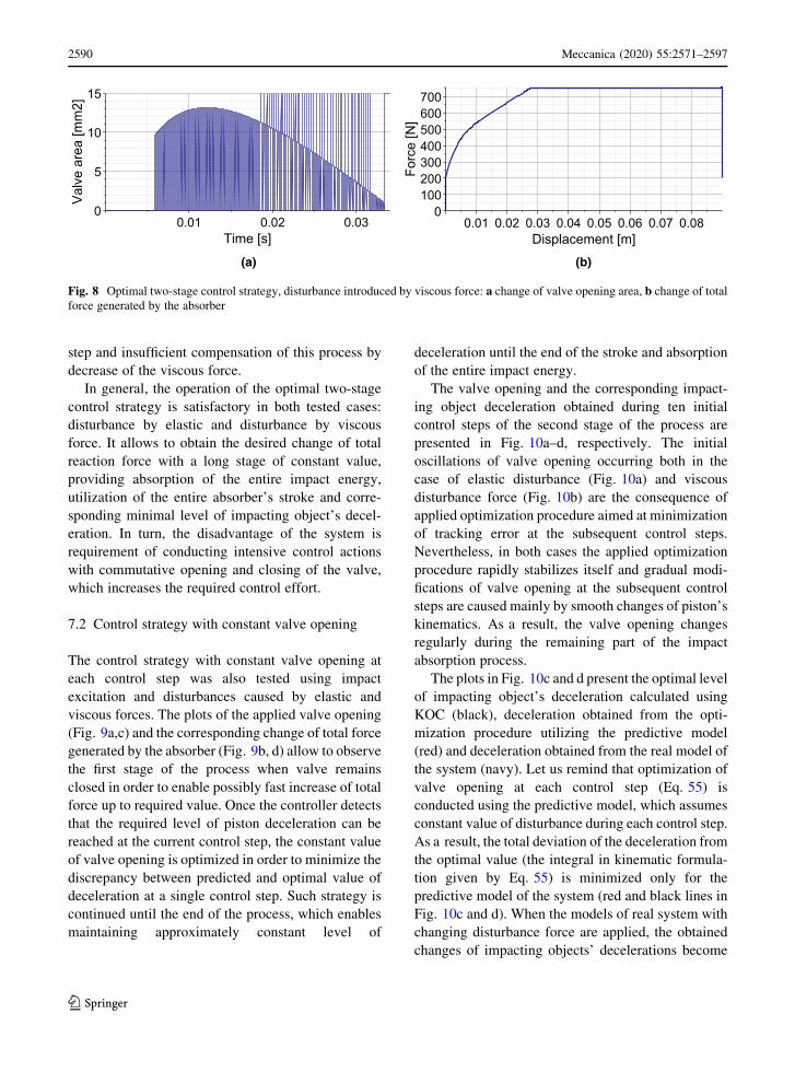
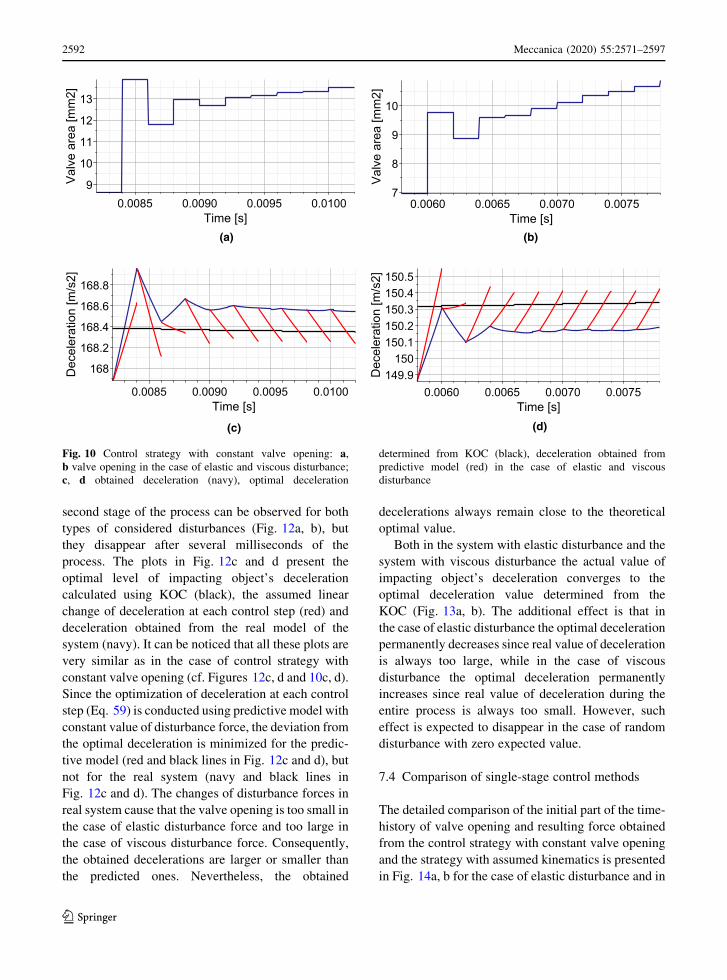
total force generated by the absorber
123
Meccanica (2020) 55:2571–2597 2589
Page 20
step and insufficient compensation of this process by
decrease of the viscous force.
In general, the operation of the optimal two-stage
control strategy is satisfactory in both tested cases:
disturbance by elastic and disturbance by viscous
force. It allows to obtain the desired change of total
reaction force with a long stage of constant value,
providing absorption of the entire impact energy,
utilization of the entire absorber’s stroke and corre-
sponding minimal level of impacting object’s decel-
eration. In turn, the disadvantage of the system is
requirement of conducting intensive control actions
with commutative opening and closing of the valve,
which increases the required control effort.
7.2 Control strategy with constant valve opening
The control strategy with constant valve opening at
each control step was also tested using impact
excitation and disturbances caused by elastic and
viscous forces. The plots of the applied valve opening
(Fig. 9a,c) and the corresponding change of total force
generated by the absorber (Fig. 9b, d) allow to observe
the first stage of the process when valve remains
closed in order to enable possibly fast increase of total
force up to required value. Once the controller detects
that the required level of piston deceleration can be
reached at the current control step, the constant value
of valve opening is optimized in order to minimize the
discrepancy between predicted and optimal value of
deceleration at a single control step. Such strategy is
continued until the end of the process, which enables
maintaining approximately constant level of
deceleration until the end of the stroke and absorption
of the entire impact energy.
The valve opening and the corresponding impact-
ing object deceleration obtained during ten initial
control steps of the second stage of the process are
presented in Fig. 10a–d, respectively. The initial
oscillations of valve opening occurring both in the
case of elastic disturbance (Fig. 10a) and viscous
disturbance force (Fig. 10b) are the consequence of
applied optimization procedure aimed at minimization
of tracking error at the subsequent control steps.
Nevertheless, in both cases the applied optimization
procedure rapidly stabilizes itself and gradual modi-
fications of valve opening at the subsequent control
steps are caused mainly by smooth changes of piston’s
kinematics. As a result, the valve opening changes
regularly during the remaining part of the impact
absorption process.
The plots in Fig. 10c and d present the optimal level
of impacting object’s deceleration calculated using
KOC (black), deceleration obtained from the opti-
mization procedure utilizing the predictive model
(red) and deceleration obtained from the real model of
the system (navy). Let us remind that optimization of
valve opening at each control step (Eq. 55) is
conducted using the predictive model, which assumes
constant value of disturbance during each control step.
As a result, the total deviation of the deceleration from
the optimal value (the integral in kinematic formula-
tion given by Eq. 55) is minimized only for the
predictive model of the system (red and black lines in
Fig. 10c and d). When the models of real system with
changing disturbance force are applied, the obtained
changes of impacting objects’ decelerations become
(a) (b)
Fig. 8 Optimal two-stage control strategy, disturbance introduced by viscous force: a change of valve opening area, b change of total
force generated by the absorber
123
2590 Meccanica (2020) 55:2571–2597
Page 21
slightly different (navy and black lines in Fig. 10c and
d). In the case of elastic disturbance the additional
elastic force is larger than in the predictive model and
real obtained deceleration is larger than the predicted
one. In turn, in the case of viscous disturbance the
additional viscous force is smaller than in the predic-
tive model and real obtained deceleration is smaller
than the predicted one. In other words, the application
of the predictive model causes that valve opening
determined at each control step is slightly too small in
the case of elastic disturbance and slightly too large in
the case of viscous disturbance. Nevertheless, the
applied strategy causes that during the entire second
stage of the process the obtained deceleration remains
close to the theoretical optimal value.
7.3 Control strategy with assumed kinematics
The similar analysis was conducted for single-stage
control strategy with assumed kinematics at each
control step. The simulations were performed both for
the case of unknown elastic disturbance force
(Fig. 11a, b) and viscous disturbance forces (Fig. 11c,
d).
The obtained results closely resemble the results
achieved previously using the control strategy with
constant valve opening at each control step (Sect. 7.2).
In particular, the first stage with closed valve provides
fast increase of generated force, while the second stage
ensures approximately constant level of generated
force. The substantial difference between control
strategy with constant valve opening and control
strategy with assumed kinematics results from the
selection of the optimized parameter. In considered
approach the valve opening changes during a single
control step in order to provide preliminary assumed
optimal change of impacting object’s deceleration. As
a result, the smooth change of the valve opening
without jumps between the subsequent steps is
observed during the main part of the impact absorption
process (Fig. 11a, c). The applied change of valve
opening instantly compensates disturbance forces
occurring in the system and, in contrast to optimal
two-stage method, no additional actions based on
sudden opening or closing of the valve are required.
The control strategy with assumed kinematics
possesses many features of the control strategy with
constant valve opening. In particular, the initial
oscillations of valve opening at the beginning of the
(a) (b)
(c) (d)
Fig. 9 Control strategy with constant valve opening at each control step: a, b the case of disturbance caused by elastic force; c, d the
case of disturbance caused by viscous force
123
Meccanica (2020) 55:2571–2597 2591
Page 22
second stage of the process can be observed for both
types of considered disturbances (Fig. 12a, b), but
they disappear after several milliseconds of the
process. The plots in Fig. 12c and d present the
optimal level of impacting object’s deceleration
calculated using KOC (black), the assumed linear
change of deceleration at each control step (red) and
deceleration obtained from the real model of the
system (navy). It can be noticed that all these plots are
very similar as in the case of control strategy with
constant valve opening (cf. Figures 12c, d and 10c, d).
Since the optimization of deceleration at each control
step (Eq. 59) is conducted using predictive model with
constant value of disturbance force, the deviation from
the optimal deceleration is minimized for the predic-
tive model (red and black lines in Fig. 12c and d), but
not for the real system (navy and black lines in
Fig. 12c and d). The changes of disturbance forces in
real system cause that the valve opening is too small in
the case of elastic disturbance force and too large in
the case of viscous disturbance force. Consequently,
the obtained decelerations are larger or smaller than
the predicted ones. Nevertheless, the obtained
decelerations always remain close to the theoretical
optimal value.
Both in the system with elastic disturbance and the
system with viscous disturbance the actual value of
impacting object’s deceleration converges to the
optimal deceleration value determined from the
KOC (Fig. 13a, b). The additional effect is that in
the case of elastic disturbance the optimal deceleration
permanently decreases since real value of deceleration
is always too large, while in the case of viscous
disturbance the optimal deceleration permanently
increases since real value of deceleration during the
entire process is always too small. However, such
effect is expected to disappear in the case of random
disturbance with zero expected value.
7.4 Comparison of single-stage control methods
The detailed comparison of the initial part of the time-
history of valve opening and resulting force obtained
from the control strategy with constant valve opening
and the strategy with assumed kinematics is presented
in Fig. 14a, b for the case of elastic disturbance and in
(a) (b)
(c) (d)
Fig. 10 Control strategy with constant valve opening: a,
b valve opening in the case of elastic and viscous disturbance;
c, d obtained deceleration (navy), optimal deceleration
determined from KOC (black), deceleration obtained from
predictive model (red) in the case of elastic and viscous
disturbance
123
2592 Meccanica (2020) 55:2571–2597
Page 23
(a) (b)
(c) (d)
Fig. 12 Control strategy with assumed kinematics at each
control step: a, b valve opening in the case of elastic and viscous
disturbance force; c, d obtained deceleration (navy), optimal
deceleration determined from KOC (black) and deceleration
obtained from predictive model (red) in the case of elastic and
viscous disturbance force
(a) (b)
(c) (d)
Fig. 11 Control strategy with assumed kinematics at each control step: a, b the case of disturbance caused by elastic force; c, d the case
of disturbance caused by viscous force
123
Meccanica (2020) 55:2571–2597 2593
Page 24
Fig. 14c, d for the case of viscous disturbance. The
plots show the initial ten control steps of the second
stage of impact absorption process. It can be clearly
seen that the strategy with assumed kinematics results
in very similar opening of the valve as the strategy
with constant valve opening. However, the continuous
change of valve opening during a single control step
causes that the valve opening rapidly becomes
continuous and smooth between the steps. Also the
change of impacting object’s deceleration obtained
using both control methods is very similar and arising
discrepancies are smaller than change of the optimal
deceleration during the process.
In general, the operation of the control strategy with
constant valve opening and the control strategy with
assumed kinematics is satisfactory both in terms of
obtained total force generated by the absorber and the
corresponding control actions. Both proposed strate-
gies allow to obtain desired change of total generated
force, which ensures utilization of the entire stroke and
(a) (b)
Fig. 13 Control strategy with assumed kinematics at each control step: convergence of the actual deceleration value (navy) to the
optimal deceleration value (black) determined using KOC, obtained in the case of elastic (a) and viscous disturbance force (b)
(a) (b)
(c) (d)
Fig. 14 Comparison of the initial part of the second stage of control strategy with constant valve opening (black) and control strategy
with assumed kinematics (navy): a, b elastic disturbance force, c, d viscous disturbance force
123
2594 Meccanica (2020) 55:2571–2597
Page 25
minimal value of obtained deceleration. They operate
properly under disturbance caused by elastic force,
disturbance caused by viscous force and thus they are
expected to operate properly in the case of arbitrary
type of disturbance forces.
The strategy with constant valve opening does not
require change of valve opening during a single control
step, but requires small step changes of constant valve
openings between the control steps during the entire
process. In turn, the strategy with assumed kinematics
requires very precise changes of valve opening at each
control step, but during the main part of the process the
valve opening changes smoothly and remains contin-
uous between the control steps. The disadvantage of the
strategy with constant valve opening is the requirement
of determining control using optimization procedure.
This drawback is eliminated in the control strategy with
assumed kinematics where the control is determined
analytically in terms of actual system state and optimal
kinematics.
8 Conclusion
Presented theoretical considerations and results of
numerical simulations prove the possibility of success-
ful application of the innovative Identification-based
Predictive Control (IPC) methods for efficient solution
of the adaptive impact mitigation problem. The
proposed methods effectively combine the concept of
on-line identification with the concept of Model
Predictive Control. Real-time identification of external
forces and system disturbances allows to develop the
efficient predictive model used for forecasting the
system response at the subsequent control steps. In turn,
repeated solving of the control problem formulated at
each control step for the finite time horizon enables
reduction of the computational cost and compensation
of the system disturbances. Moreover, application of
the kinematic optimality condition, which is recalcu-
lated at each control step and incorporated into the
successively solved control problems, allows for effi-
cient tracking of the globally optimal solution.
Three different implementations of the IPC pre-
sented in this paper directly follow the above paradigm
of adaptive predictive control. The optimal two-stage
method provides the best possible solution of the
control problem, but requires intensive control actions
during the entire impact absorption process. The
method with constant valve opening provides very
similar response, but requires smaller control modifi-
cations with gradual change of valve opening. The
method with assumed kinematics provides large
versatility due to possibility of adopting various
functions describing the system kinematics and it
results in relatively smooth change of valve opening.
Moreover, the suboptimal control can be determined
analytically at a low numerical cost.
The proposed innovative control methods provide
fully adaptive operation of semi-active shock-ab-
sorbers and efficient mitigation of dynamic excitations
under the presence of disturbances. The exceptional
capabilities of the described control strategies cause
that they can be widely applied in various semi-active
shock-absorbing devices and used in many branches of
engineering. Practical implementation of the proposed
IPC methods requires the use of very fast actuators,
which can be based on piezoelectric or magneto-
rheological valves with electromagnets, and efficient
data processing systems, such as FPGA modules. As
both the executive systems and the data processing and
control systems have been successfully applied for
adaptive impact mitigation problems, it can be con-
cluded that the proposed Identification-based Predic-
tive Control is feasible. Experimental validation of the
proposed approach constitutes a goal of future
research of the authors.
Acknowledgements The support of the National Science
Centre, Poland, granted through the Agreement 2018/31/D/ST8/
03178, and the National Centre for Research and Development
(NCBiR) granted through the Agreement LIDER/13/0063/L-10/
18/NCBR/2019 is gratefully acknowledged. RF is supported by
the Foundation for Polish Science (FNP) under the START
scholarship.
Compliance with ethical standards
Conflict of interest The authors declare that they have no
conflict of interest.
Open Access This article is licensed under a Creative Com-
mons Attribution 4.0 International License, which permits use,
sharing, adaptation, distribution and reproduction in any med-
ium or format, as long as you give appropriate credit to the
original author(s) and the source, provide a link to the Creative
Commons licence, and indicate if changes were made. The
images or other third party material in this article are included in
the article’s Creative Commons licence, unless indicated
otherwise in a credit line to the material. If material is not
included in the article’s Creative Commons licence and your
intended use is not permitted by statutory regulation or exceeds
123
Meccanica (2020) 55:2571–2597 2595
Page 26
the permitted use, you will need to obtain permission directly
from the copyright holder. To view a copy of this licence, visit
http://creativecommons.org/licenses/by/4.0/.
References
1. Ghiringhelli GL (2000) Testing of semi-active landing gear
control for a general aviation aircraft. AIAA J Aircraft
37(4):606–616
2. Mikułowski G, Holnicki-Szulc J (2007) Adaptive landing
gear concept - feedback control validation. Smart Mater
Struct 16:2146–2158
3. Wang H, Rui Q, Hong H, Li J (2017) Airdrop recovery
systems with self-inflating airbag: modeling and analysis,
1st edn. National Defense Industry Press, Beijing
4. Baruh H, Elsayed EA (2018) Experimental design of a
folded-structure energy-absorption system. Int J Mater Prod
Technol 56(4):341–362
5. Wołejsza Z, Holnicki-Szulc J, Graczykowski C, Hinc K,
Faraj R, Kowalski T, Mikułowski G, Kazmierczak K,
Wiszowaty R, Pawłowski P (2018) Dynamics and control of
adaptive airbags for UAV impact protection. In: ISMA
2018/USD 2018, international conference on noise and
vibration engineering/international conference on uncer-
tainty in structural dynamics, Leuven, Belgium,
pp 3661–3670
6. Maeda T, Otsuki M, Hashimoto T (2019) Protection against
overturning of a lunar-planetary lander using a controlled
landing gear. Proc Inst Mech Eng Part G J Aerosp Eng
233(2):438–456
7. Jawad SAW (1996) Intelligent hydraulic bumper for
frontal collision mitigation. ASME Appl Mech Div
218:181–189
8. Woo D, Choi S-B, Choi YT, Wereley NM (2007) Frontal
crash mitigation using MR impact damper for controllable
bumper. J Intell Mater Syst Struct 18(12):1211–1215
9. Myung-Hyun N, Sang-Youl L (2018) Parametric impact
performances in a new type crash cushion barrier system
using an energy absorption pipe. Int J Crashworth, pp 1–14,
in press
10. Richert J, Coutellier D, Gotz C, Eberle W (2007) Advanced
smart airbags: the solution for real-life safety? Int J Crash-
worthiness 12:159–171
11. Graczykowski C, Holnicki-Szulc J (2009) Protecting
offshore wind turbines against ship impacts by
means of adaptive inflatable structures. Shock Vib 16(4):
335–353
12. Spaggiari A, Dragoni E (2012) Efficient dynamic modelling
and characterization of a magnetorheological damper.
Meccanica 47(8):2041–2054
13. Powers BE, Wereley NM, Choi YT (2016) Analysis of
impact loads in a magnetorheological energy absorber using
a Bingham plastic model with refined minor loss factors
accounting for turbulent transition. Meccanica
51(12):3043–3054
14. Makowski M, Knap L (2014) Reduction of wheel force
variations with magnetorheological devices. J Vib Control
20(10)
15. Makowski M, Knap L (2018) Investigation of an off-road
vehicle equipped with magnetorheological dampers. Adv
Mech Eng 10(5)
16. Lou Z, Ervin R, Filisko F, Winkler C (1993) An elec-
trorheologically controlled semi-active landing gear. SAE
Trans 102:334–342
17. Nguyen QH, Choi SB, Park YG (2012) An analytical
approach to optimally design of electrorheological fluid
damper for vehicle suspension system. Meccanica
47(7):1633–1647
18. Zalewski R, Chodkiewicz P (2016) Semi-active linear
vacuum packed particles damper. J Theoret Appl Mech
54(1):311–316. https://doi.org/10.15632/jtam-pl.54.1.311
19. Bartkowski P, Zalewski R (2018) A concept of smart mul-
tiaxial impact damper made of vacuum packed particles. In:
MATEC web of conferences, 157, Art. No. 05001, https://
doi.org/10.1051/matecconf/201815705001
20. Mikułowski G, Wiszowaty R (2016) Pneumatic adaptive
absorber: mathematical modelling with experimental veri-
fication. Math Probl Eng 7074206-1-14
21. Wasilewski M, Pisarski D, Bajer CI (2019) Adaptive opti-
mal control for seismically excited structures. Autom
Constr 106:1–18
22. Popławski B, Mikułowski G, Mroz A, Jankowski Ł (2018)
Decentralized semi-active damping of free structural
vibrations by means of structural nodes with an on/off
ability to transmit moments. Mech Syst Signal Process
100:926–939
23. Wasilewski M, Pisarski D, Konowrocki R, Bajer CI (2019)
A new efficient adaptive control of torsional vibrations
induced by switched nonlinear disturbances. Int J Appl
Math Comput Sci 29(2):285–303
24. Holnicki-Szulc J, Graczykowski C, Mikułowski G, Mroz A,
Pawłowski P, Wiszowaty R (2015) Adaptive impact
absorption - the concept and potential applications. Int J Prot
Struct 6(2):357–377
25. Holnicki-Szulc J, Mackiewicz A, Kołakowski P (1998)
Design of adaptive structures for improved load capacity.
AIAA J 36(3):471–476
26. Jankowski Ł, Graczykowski C, Pawłowski P, Mikułowski
G, Ostrowski M, Popławski B, Faraj R, Suwała G, Holnicki-
Szulc J (2017) Adaptive self-protection against shock and
vibration. Adv Sci Technol 101:133–142
27. Sekuła K, Graczykowski C, Holnicki-Szulc J (2013) On-
line impact load identification. Shock Vib 20(1):123–141
28. Ilchmann A, Sawodny O, Trenn S (2016) Pneumatic
cylinders: modelling and feedback force control. Int J
Control 79(6):650–661
29. Wang J, Pu J, Moore P (1999) A practical control strategy
for servo-pneumatic actuator systems. Control Eng Pract
7:1483–1488
30. Faraj R, Graczykowski C, Holnicki-Szulc J (2018) Adapt-
able pneumatic shock absorber. J Vib Control 25(3):711–721
31. Ghiringhelli GL, Gualdi S (2004) Evaluation of a landing
gear semi-active control system for complete aircraft land-
ing. Aerotecnica Missili e Spazio 83:21–31
32. Wang H, Xing JT, Price WG, Li W (2008) An investigation
of an active landing gear system to reduce aircraft vibrations
caused by landing impacts and runway excitations. J Sound
Vib 317:50–66
123
2596 Meccanica (2020) 55:2571–2597
Page 27
33. Sivakumar S, Haran A (2013) Mathematical model and
vibration analysis of aircraft with active landing gears. J Vib
Control 21(2):229–245
34. Hui L, Hongbin G, Dawei C (2008) Application of high-
speed solenoid valve to the semi-active control of landing
gear. Chin J Aeronaut 21(3):232–240
35. Graczykowski C, Faraj R (2019) Development of control
systems for fluid-based adaptive impact absorbers. Mech
Syst Signal Process 122(2019):622–641
36. Faraj R, Graczykowski C (2019) Hybrid prediction control
for self-adaptive fluid-based shock-absorbers. J Sound Vib
449:427–446
37. Faraj R, Mikułowski G, Wiszowaty R (2020) Smart mater
Struct 29(11):115008. https://doi.org/10.1088/1361-665X/
ab9adc
38. Graczykowski C, Pawłowski P (2017) Exact physical model
of magnetorheological damper. Appl Math Model. https://
doi.org/10.1016/j.apm.2017.02.035
39. Faraj R (2019) Development of self-adaptive systems for
mitigation of response under dynamic excitation, PhD
Thesis, IPPT PAN
Publisher’s Note Springer Nature remains neutral with
regard to jurisdictional claims in published maps and
institutional affiliations.
123
Meccanica (2020) 55:2571–2597 2597