Open Journal of Composite Materials, 2017, 7, 185-196 http://www.scirp.org/journal/ojcm
ISSN Online: 2164-5655 ISSN Print: 2164-5612
DOI: 10.4236/ojcm.2017.74012 July 27, 2017
Identification of Damage Parameters for Intralaminar Damage Modeling in Laminated Composites Considering Transverse Stress Effects
Rehs T. Gerrit1, Shun Kokubo2, Tomohiro Yokozeki2
1Department of Mechanical Engineering, Technische Universität, Darmstadt, Germany 2Department of Aeronautics and Astronautics, The University of Tokyo, Tokyo, Japan
Abstract The aim of this study is to develop an appropriate modeling methodology for the simulation of intralaminar damage in laminated composites under com-plex loadings. The intralaminar damages are modeled by stiffness reduction controlled by thermodynamic forces as defined in continuum damage me-chanics model proposed by Ladevèze. The original method neglected trans-verse stress in elementary plies during the tensile tests of [45/−45]mS lami-nates, resulting in variations of the identified damage parameters of Ladevèze model. This study compared the identified damage parameters considering transverse stress effects with those based on the original method. The effect of transverse stress in the identification process on the damage modeling is dis-cussed, and it is found that one of damage coupling parameters and the dam-age master curves significantly depend on consideration of transverse stress effects. Finally, it is demonstrated that experimental stiffness degradation is well simulated by the prediction using the identified parameters considering transverse stress effects.
Laminated composites are widely used in aerospace and automotive application because of its high specific stiffness and strength. These light-weight characteris-
tics motivated us to apply the composites to their primary structures. Generally, composites exhibit significant anisotropic mechanical behavior as well as com-plex damage accumulation process (fiber breakage, fiber/matrix interfacial de-bonding, microcracks, delaminations, etc.) compared to traditional isotropic metal/polymer materials [1]-[10]. As application-related damage tolerance con-sideration (e.g. foreign object damages, crashing behavior, and fatigue damages) is required for the design of primary structures, it is necessary to develop a so-phisticated but tractable damage simulation tool to express the above-mentioned mechanical and damage behavior of composites.
Continuous carbon fiber laminated composites are expected to be good can-didates for primary aerospace/automobile structures. Composites consist of reinforced fibers and polymer matrix. Multiscale modeling which can connect microstructures (fibers and matrix, fiber architectures etc.) to overall structures has been actively investigated, and computational cost and complex programs prevent the designers and the engineers from using the precise modelling. Me-soscale modeling (i.e. ply-level homogeneous modeling) using continuum dam-age mechanics is a cost-efficient and tractable way to simulate complex damage processes in laminated composites for structural design [11] [12] [13] [14] [15]. Large-scale damages (e.g. delaminations) are often modeled by cohesive zone modeling [16] [17] [18], which can be easily combined with continuum damage mechanics. Therefore, the present paper takes a mesoscale stand, in which intra-laminar damages are modeled by continuum damage mechanics and interlami-nar damages are simulated by cohesive zone models, for the development of effi-cient design tool of composite structures. The present study focuses on the intralaminar damage modeling, although interlaminar modeling is also to be incorporated as the future work.
Regarding the continuum damage mechanics of laminated composites, La-devèze and Le Dantec [11] constructed a continuum damage model for intrala-minar mechanical behavior of laminated composite, taking stiffness reduction, fiber elastic nonlinearity, and matrix plasticity into account. This model can de-scribe the brittle fracture of fiber, matrix microcracking and fiber/matrix inter-facial debonding as damage parameters. Casari [12] extended the model to three-dimensional woven composite. This study applied Ladevèze model to con-sider intralaminar damages in laminated composites. In the identification process of the damage parameters as shown in Ladevèze and Le Dantec [11], [0/90]mS, [45/−45]mS, [67.5/−67.5]mS laminates are used to measure stress-strain responses. During this experimental analysis, the original method neglected transverse stress normal to fiber direction in elementary plies of [45/−45]mS la-minates. However, tensile loadings applied to [45/−45]mS laminates induces in-plane transverse stress as well as shear stresses in each ply, both of which are to be taken into account in the identification process of damage coupling para-meters. The present study investigates the effect of consideration of transverse stress during the experimental data analysis of [45/−45]mS laminates on the damage parameters of Ladevèze model.
R. T. Gerrit et al.
187
The following sections describe the summary of Ladevèze model and the original experimental identification process of damage parameters, followed by the modified identification process proposed in this study. Experiments for the parameter identification are explained, and the parameters obtained by the original and modified method are presented with discussions on the effect of transverse stress in the identification process on the damage modeling.
2. Intralaminar Damage Modeling 2.1. Ladevèze Model [11]
Basis of the Ladevèze theory is the strain energy function of a damaged ply in a two dimensional formulation, shown in Equation (1):
( ) ( ) ( )
2 22 222 222 11 12 12
11 220 0 0 0 01 11 1 2 22 2 12 122 1 2 1 2 2 1
DdE
E d E E d E G dσ σσ ν σ
σ σ + −= − + + +− − −
(1)
In this equation, damage parameters, dij, are introduced to relate the elastic modulus to the damage state. 0
iE and 0ijG are initial Young’s modulus and
shear modulus, respectively, σij is stress, νij is Poisson’s ratio, and subscripts 1 and 2 represents direction along fiber and transverse to the fiber, respectively. < >+ and < >− are valid when the value is positive and negative, respectively (i.e. <a>+= a when a is positive, and <a>+ = 0 when a is negative). Note the crack closure under compressive transverse stress is considered. An increase of dij will result in a decrease of the modulus, resulting in the following strain-stress rela-tionship of a damaged ply:
( )
( )
( )
120 01 11 1
11 11212
22 220 01 2 22
12 12
012 12
1 01
1 01
10 01
Dd
ijij
E d EE
E E d
G d
ν
ε σν
ε ε σσ
γ σ
−
− ∂ = → = − ∂ −
−
(2)
In the continuum damage mechanics model, thermodynamic forces, Yij, that drive the damage accumulation can be derived from the partial derivative of strain energy with respect to dij.
( ) ( ) ( )
22 22211 12
11 22 122 2 20 0 011 1 22 2 12 12
, ,2 1 2 1 2 1
Y Y Yd E d E d G
σσ σ+= = =− − −
(3)
Figure 1 shows the typical relationship between the damage parameters, dij, and the thermodynamic forces, Yij of fiber-reinforced composites. In the fiber direction, d11 reflects the brittle nature of fiber-dominated fractures; d11 is set to be 0 at the initial stage, and a sudden jump to 1 takes place. The transverse and shear damages exhibit progressive accumulation; d22 and d12 are represented as a linear equation, polynomial form or other expressions of the thermodynamic forces. In general, transverse stresses and shear stresses induce matrix damages and fiber/matrix interfacial damages, which in turn results in transverse and
R. T. Gerrit et al.
188
Figure 1. Typical relationships between damage parameters and thermodynamic forces. shear modulus reduction. Thus, the transverse and shear components of ther-modynamic force and damage parameters should be coupled. The following coupling parameters (b2 and b3) are defined to account for this coupling effect:
2 22 12Y b Y Y= + (4)
22 3 12d b d= (5)
Y is referred to as an equivalent thermodynamic force. The undamaged elastic properties and the damage curves (d11-Y11, and d12-Y, d22-Y) are identified from the tensile tests of the laminated composites, as explained in the next section. In addition, nonlinear elastic parameters in the fiber direction and plastic parame-ters are also to be determined [11].
2.2. Procedure for Parameter Identification
Ladevèze and Le Dantec [11] proposed to use [0/90]mS, [45/−45]mS, and [67.5/− 67.5]mS laminates to identify the elastic, non-linear, and damage parameters. The overall longitudinal stress, σL, and the longitudinal and transverse strains, εL and εT, of three kinds of laminates are obtained from the monotonic and cyclic ten-sile tests. Elastic properties can be easily obtained based on initial slopes in stress-strain curves of [0/90]mS, [45/−45]mS, and [67.5/−67.5]mS laminates [11]. This section emphasizes the identification process of damage parameters. Let the in-plane stiffness matrix of an undamaged unidirectional ply have the following form:
11 11 12 11
22 12 22 22
12 66 12
00
0 0
Q QQ Q
Q
σ εσ εσ γ
=
(6)
Fiber direction Shear direction
Transverse directionct YorY 1111
11Y12Y
12222 YYbY +=
12322 dbd =
122 =d
111 =d 112 =d
22d
11d 12d
012Y sY12
( )1212 Yfd =
22d12d
sY22
R. T. Gerrit et al.
189
In the case of [0/90]mS laminates in unidirectional tension, local stress and strain of 0-degree ply can be expressed in terms of overall stress and strain by
( )( )
211 11 22 12
11 112 211 22 12
2 4,
4L L
Q Q Q Q
Q Q Qσ σ ε ε
+ −= =
+ − (7)
For the angle-ply laminates, [θ/−θ]mS under uniaxial tensile loading, local transverse and shear stresses/strains in each ply is calculated by
( ) ( )2 2 2 212 22 12 22
22 2
2 222
cos sin sin cos
sin cos
YY XYL
XX YY XY
L T
Q Q Q Q Q Q
Q Q Q
θ θ θ θσ σ
ε ε θ ε θ
+ − +=
−
= +
(8)
( )
( )
6612 2
12
2 cos sin
2 cos sin
XY YYL
XX YY XY
L T
Q Q Q
Q Q Q
θ θσ σ
γ ε ε θ θ
+=
−
= −
(9)
where the following equations hold:
( )( ) ( )
( )
4 2 2 411 12 66 22
2 2 4 411 22 66 12
4 2 2 411 12 66 22
cos 2 2 cos sin sin
4 cos sin cos sin
sin 2 2 cos sin cos
XX
XY
YY
Q Q Q Q Q
Q Q Q Q Q
Q Q Q Q Q
θ θ θ θ
θ θ θ θ
θ θ θ θ
= + + +
= + − + +
= + + +
(10)
Specifically, in the case of [45/−45]mS laminates, the following simple equa-tions are derived for shear stress-strain relationship:
12
12
12 L
L T
σ σ
γ ε ε
=
= − (11)
To identify the damage evolution curves, σ12-γ12 curves of [45/−45]mS laminates and σ12-γ12 and σ22-ε22 curves of [67.5/−67.5]mS laminates using Equations (8)-(11). Note that Equations (8)-(10) are affected by variations of elastic prop-erties owing to intralaminar damage accumulation. We neglect the dam-age-induced variations and Equations (8)-(9) are used for identification of dam-age parameters as suggested by Ladevèze and Le Dantec [11].
Cyclic tensile tests provide the relationship between the damage parameters (i.e. stiffness slope reduction) and the corresponding thermodynamic forces at maximum stress in the cycles using Equation (3). Three damage curves, d12-Y12 from [45/−45]mS laminates, d12-Y12 from [67.5/−67.5]mS laminates, and d22-Y22 from [67.5/−67.5]mS laminates, are obtained from the experimental curves. The coupling parameters, b2 and b3, are determined such that three curves (dij-Y curves) are collapsed into a single master curve considering Equations (4) and (5). The fitted damage curve (i.e. d12 = f(Y)) and coupling parameters are used for damage simulation in the Ladevèze model.
2.3. Effect of Transverse Stress in [45/−45]mS Laminates
In the previous section, transverse stress and strain in each ply of [45/−45]ms la-minates are neglected. Actually, when θ is equal to 45degree, Equation (8) is ex-
R. T. Gerrit et al.
190
pressed as
( )
22 1222
11 22 12
22
212
L
L T
Q QQ Q Q
σ σ
ε ε ε
+=
+ +
= +
(12)
Thus, in the case of laminates made of carbon fiber-reinforced unidirectional plies, σ22 and ε22 can be approximately regarded as zero. However, transverse stress and strain exist, and these components are possibly taken into account in some cases (e.g. glass fiber-reinforced plastics). The present study investigates this effect on the identification of damage parameters. In the previous method (denoted as Case-A), three damage curves (d12-Y12 from [45/−45]mS laminates, d12-Y12 from [67.5/−67.5]mS laminates, and d22-Y22 from [67.5/−67.5]mS) are uti-lized for the identification. If we consider Equation (12), Y22 is also taken into account for [45/−45]mS laminates in uniaxial tension, and one additional damage curve (i.e. d22-Y22 from [45/−45]mS) is obtained. We need to consider the mod-ified processes to determine the coupling parameters, b2 and b3, by finding a sin-gle master curve based on damage curves (dij-Y curves), which are discussed in the following sections.
3. Experimental 3.1. Experimental Procedure
The present study focuses on the damage curves. [0/90]2S, [45/−45]2S, and [67.5/67.5]2S specimens were prepared using unidirectional glass fibers and epoxy matrix. The specimens are 120 mm in length (excluding the clamp area), 25 mm in width, and about 4 mm in thickness. Back-to-back strain gauges were attached in the longitudinal and transverse directions to the specimens to ac-quire εL and εT. First, quasi-static monotonic tensile tests of the three laminates were conducted to obtain the elastic parameters and the suggested load levels for the cyclic tension tests. Then, cyclic tension tests of [45/−45]2S, and [67.5/67.5]2S specimens were carried out to derive the damage parameters. All tensile tests were performed in reference to JIS K7161.
3.2. Analysis of Experimental Data
Typical stress-strain curves obtained by quasi-static monotonic tensile tests of three laminates are presented in Figure 2. The elastic parameters are then eva-luated following the previous study [11], and summarized in Table 1. Cyclic tensile results of [45/−45]2S, and [67.5/67.5]2S specimens were converted to the stress-strain relationships in the local direction using Equations (8)-(12). A typ-ical in-plane shear stress-shear strain curve obtained by cyclic tests of [45/−45]2S laminates is shown in Figure 3. The black solid lines indicate the apparent shear moduli of damaged laminates, from which we can evaluate the damage parame-ters d12 (as defined in Equation (2)) as a function of the applied maximum stress (or the corresponding thermodynamic force) during each cycle. The d12-Y12
R. T. Gerrit et al.
191
Figure 2. Stress-strain (σL-εL) curves obtained by quasi-static monotonic tensile tests of three laminates.
Figure 3. In-plane shear stress-shear strain curve obtained by cyclic tests of [45/−45]2S laminates.
R. T. Gerrit et al.
192
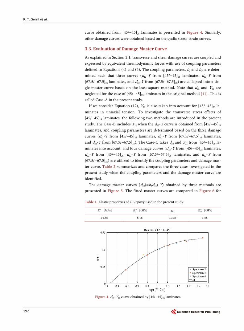
curve obtained from [45/−45]2S laminates is presented in Figure 4. Similarly, other damage curves were obtained based on the cyclic stress-strain curves.
3.3. Evaluation of Damage Master Curve
As explained in Section 2.1, transverse and shear damage curves are coupled and expressed by equivalent thermodynamic forces with use of coupling parameters defined in Equations (4) and (5). The coupling parameters, b2 and b3, are deter-mined such that three curves (d12-Y from [45/−45]2S laminates, d12-Y from [67.5/−67.5]2S laminates, and d22-Y from [67.5/−67.5]2S) are collapsed into a sin-gle master curve based on the least-square method. Note that d22 and Y22 are neglected for the case of [45/−45]2S laminates in the original method [11]. This is called Case-A in the present study.
If we consider Equation (12), Y22 is also taken into account for [45/−45]2S la-minates in uniaxial tension. To investigate the transverse stress effects of [45/−45]2S laminates, the following two methods are introduced in the present study. The Case-B includes Y22 when the d12-Y curve is obtained from [45/−45]2S laminates, and coupling parameters are determined based on the three damage curves (d12-Y from [45/−45]2S laminates, d12-Y from [67.5/−67.5]2S laminates, and d22-Y from [67.5/−67.5]2S). The Case-C takes d22 and Y22 from [45/−45]2S la-minates into account, and four damage curves (d12-Y from [45/−45]2S laminates, d22-Y from [45/−45]2S, d12-Y from [67.5/−67.5]2S laminates, and d22-Y from [67.5/−67.5]2S) are utilized to identify the coupling parameters and damage mas-ter curve. Table 2 summarizes and compares the three cases investigated in the present study when the coupling parameters and the damage master curve are identified.
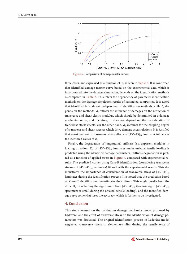
The damage master curves (d22(=b3d12)-Y) obtained by three methods are presented in Figure 5. The fitted master curves are compared in Figure 6 for
Table 1. Elastic properties of GF/epoxy used in the present study.
01E [GPa] 0
2E [GPa] v12 012G [GPa]
24.35 8.16 0.328 3.58
Figure 4. d12-Y12 curve obtained by [45/−45]2S laminates.
R. T. Gerrit et al.
193
Figure 5. Damage master curves obtained by three methods.
Table 2. Comparison of identification method for coupling parameters and damage master curve.
Identification method [45/−45]2S [67.5/−67.5]2S
d12-Y d22-Y d12-Y d22-Y
Case-A (traditional method) (Y = Y12) N/A
Case-B (Y = b2Y22+ Y12) N/A
Case-C (Y = b2Y22+ Y12)
R. T. Gerrit et al.
194
Figure 6. Comparison of damage master curves.
three cases, and expressed as a function of Y, as seen in Table 3. It is confirmed that identified damage master curve based on the experimental data, which is incorporated into the damage simulation, depends on the identification methods as compared in Table 2. This infers the dependency of parameter identification methods on the damage simulation results of laminated composites. It is noted that identified b3 is almost independent of identification methods while b2 de-pends on the methods. b3 reflects the influence of damages on the reduction of transverse and shear elastic modulus, which should be determined in a damage mechanics sense, and therefore, it does not depend on the consideration of transverse stress effects. On the other hand, b2 accounts for the coupling degree of transverse and shear stresses which drive damage accumulations. It is justified that consideration of transverse stress effects of [45/−45]2S laminates influences the identified values of b2.
Finally, the degradation of longitudinal stiffness (i.e. apparent modulus in loading direction, EL) of [45/−45]2S laminates under uniaxial tensile loading is predicted using the identified damage parameters. Stiffness degradation is plot-ted as a function of applied stress in Figure 7, compared with experimental re-sults. The predicted curves using Case-B identification (considering transverse stresses of [45/−45]2S laminates) fit well with the experimental results. This de-monstrates the importance of consideration of transverse stress of [45/−45]2S laminates during the identification process. It is noted that the prediction based on Case-C identification overestimates the stiffness. This might results from the difficulty in obtaining the d22-Y curve from [45/−45]2S (because d22 in [45/−45]2S specimens is small during the uniaxial tensile loading), and the identified dam-age curve somewhat loses the accuracy, which is further to be investigated.
4. Conclusion
This study focused on the continuum damage mechanics model proposed by Ladevèze, and the effect of transverse stress on the identification of damage pa-rameters was discussed. The original identification process in Ladevèze model neglected transverse stress in elementary plies during the tensile tests of
R. T. Gerrit et al.
195
Figure 7. Stiffness degradation of [45/−45]2S laminates under uniaxial tensile loadings: comparison between simulated re-sults and experimental results.
Table 3. Estimated coupling parameters and damage curves based on three different me-thods.
[45/−45]mS laminates, resulting in difference in the identified damage parame-ters. This study compared the identified damage parameters considering trans-verse stress effects with those based on the original method. The effect of trans-verse stress in the identification process on the damage modeling was discussed, and it was found that consideration of transverse stress effects significantly af-fects one of damage coupling parameters and the damage master curves. Finally, it is demonstrated that experimental stiffness degradation is well simulated by the prediction using the identified parameters considering transverse stress ef-fects.
References [1] Garrett, K.W. and Bailey, J.E. (1977) Multiple Transverse Fracture in 90o Cross-Ply
Laminates of a Glass Fiber-Reinforced Polyester. Journal of Materials Science, 12, 157-168. https://doi.org/10.1007/BF00738481
[2] Joshi, S.P. and Sun, C.T. (1985) Impact Induced Fracture in a Laminated Compo-site. Journal of Composite Materials, 19, 51-66.
[3] Kim, R.Y. and Soni, S.R. (1984) Experimental and Analytical Studies on the Onset of Delamination in Laminated Composites. Journal of Composite Materials, 18, 70-80.
[4] Ogihara, S., Kobayashi, S. and Reifnider, K.L. (2003) Characterization of Nonlinear Behavior of Carbon/Epoxy Unidirectional and Angle-Ply Laminates. Advanced Composite Materials, 11, 239-254. https://doi.org/10.1163/156855102762506281
[5] Yokozeki, T., Aoki, T., Ogasawara, T. and Ishikawa, T. (2005) Effects of Layup An-gle and Ply Thickness on Matrix Crack Interaction in Contiguous Plies of Compo-site Laminates. Composites Part A: Applied Science and Manufacturing, 36, 1229- 1235. https://doi.org/10.1016/j.compositesa.2005.02.002
[6] Yokozeki, T., Ogasawara, T. and Ishikawa, T. (2006) Nonlinear Behavior and Com-pressive Strength of Unidirectional and Multidirectional Carbon Fiber Composite Laminates. Composites Part A: Applied Science and Manufacturing, 37, 2069-2079. https://doi.org/10.1016/j.compositesa.2005.12.004
[7] Yoshimura, A., Yashiro, S., Okabe, T. and Takeda, N. (2007) Characterization of Tensile Damage Progress in Stitched CFRP Laminates. Advanced Composite Mate-rials, 16, 223-244. https://doi.org/10.1163/156855107781393740
[8] Prabhakar, P. and Waas, A.M. (2013) Interaction between Kinking and Splitting in the Compressive Failure of Unidirectional Fiber Reinforced Laminated Composites. Composite Structures, 98, 85-92. https://doi.org/10.1016/j.compstruct.2012.11.005
[9] Suemasu, H. (2016) Analytical Approaches to Compression after Impact (CAI) Be-havior of Carbon Fiber-Reinforced Composite Materials. Advanced Composite Materials, 25, 1-18. https://doi.org/10.1080/09243046.2015.1122416
[10] Ueda, M., Kimura, K. and Jeong, T.-K. (2016) In situ Observation of Kink-Band Formation in a Unidirectional Carbon Fiber Reinforced Plastic by X-Ray Computed Tomography Imaging. Advanced Composite Materials, 25, 31-43. https://doi.org/10.1080/09243046.2014.973173
[11] Ladeveze, P. and Le Dantec, E. (1992) Damage Modeling of the Elementary Ply for Laminated Composites. Composites Science and Technology, 43, 257-267. https://doi.org/10.1016/0266-3538(92)90097-M
[12] Casari, P., Ladeveze, P. and Chou, T.W. (1999) Damage Modeling and Characteri-zation of a Three-Dimensional Woven Composite. Proceedings of 12th Interna-tional Conference on Composite Materials, Paris, 5-9 July 1999, 717.
[13] Matzenmiller, A., Lubliner, J. and Taylor, R.L. (1995) A Constitutive Model for Anisotropic Damage in Fiber-Composite. Mechanics of Materials, 20, 125-152. https://doi.org/10.1016/0167-6636(94)00053-0
[14] Allix, O., Ladeveze, P. and Vittecoq, E. (1994) Modelling and Identification of the Mechanical Behaviour of Composite Laminates in Compression. Composites Science and Technology, 51, 35-42. https://doi.org/10.1016/0266-3538(94)90154-6
[15] Lapczyk, I. and Hurtado, J.A. (2007) Progressive Damage Modeling in Fi-ber-Reinforced Materials. Composites Part A: Applied Science and Manufacturing, 38, 2333-2341. https://doi.org/10.1016/j.compositesa.2007.01.017
[16] Geubelle, P.H. and Baylor, J.S. (1998) Impact-Induced Delamination of Composites: A 2D Simulation. Composites Part B: Engineering, 29, 589-602. https://doi.org/10.1016/S1359-8368(98)00013-4
[17] Turon, A., Camanho, P.P., Costa, J. and Davila, C.G. (2006) A Damage Model for the Simulation of Delamination in Advanced Composites under Variable-Mode Loading. Mechanics of Materials, 38, 1072-1089. https://doi.org/10.1016/j.mechmat.2005.10.003
[18] Li, S., Thouless, M.D., Waas, A.M., Schroeder, J.A. and Zavattieri, P.D. (2005) Use of a Cohesive-Zone Model to Analyze the Fracture of a Fiber-Reinforced Poly-mer-Matrix Composite. Composites Science and Technology, 65, 537-549. https://doi.org/10.1016/j.compscitech.2004.08.004
Submit or recommend next manuscript to SCIRP and we will provide best service for you:
Accepting pre-submission inquiries through Email, Facebook, LinkedIn, Twitter, etc. A wide selection of journals (inclusive of 9 subjects, more than 200 journals) Providing 24-hour high-quality service User-friendly online submission system Fair and swift peer-review system Efficient typesetting and proofreading procedure Display of the result of downloads and visits, as well as the number of cited articles Maximum dissemination of your research work
Submit your manuscript at: http://papersubmission.scirp.org/ Or contact [email protected]