6POWER Consortium Title: Document Version: Deliverable D4.8 Identification of IPv6-Enabled Devices to be Used in Home Automation 2.5 Project Number: Project Acronym: Project Title: IST-2001-37613 6POWER IPv6, QoS & Power Line Integration Contractual Delivery Date: Actual Delivery Date: Deliverable Type* - Security**: 31/12/2002 07/01/2003 R – PU * Type: P - Prototype, R - Report, D - Demonstrator, O - Other ** Security Class: PU- Public, PP – Restricted to other programme participants (including the Commission), RE – Restricted to a group defined by the consortium (including the Commission), CO – Confidential, only for members of the consortium (including the Commission) Responsible and Editor/Author: Organization: Contributing WP: Antonio F. Gómez Skarmeta UMU WP4 Authors (organizations): Jordi Palet (Consulintel), Daniel Martínez (UMU), Juan José Pujante (UMU). Abstract: This document analyses the existing products for home automation, and tries to identify suitable technologies and devices which allow for remote end-to-end appliance management over IPv6, in a way that can be integrated into the 6POWER project. Keywords: Home Automation, IPv6, PLC, Power Line Communications
Transcript
6POWER Consortium
Title: Document Version:
Deliverable D4.8 Identification of IPv6-Enabled Devices to be Used in Home Automation 2.5
Project Number: Project Acronym: Project Title:
IST-2001-37613 6POWER IPv6, QoS & Power Line Integration
Contractual Delivery Date: Actual Delivery Date: Deliverable Type* - Security**:
31/12/2002 07/01/2003 R – PU * Type: P - Prototype, R - Report, D - Demonstrator, O - Other ** Security Class: PU- Public, PP – Restricted to other programme participants (including the Commission), RE – Restricted to a group
defined by the consortium (including the Commission), CO – Confidential, only for members of the consortium (including the Commission)
Responsible and Editor/Author: Organization: Contributing WP:
Antonio F. Gómez Skarmeta UMU WP4
Authors (organizations):
Jordi Palet (Consulintel), Daniel Martínez (UMU), Juan José Pujante (UMU).
Abstract:
This document analyses the existing products for home automation, and tries to identify suitable technologies and devices which allow for remote end-to-end appliance management over IPv6, in a way that can be integrated into the 6POWER project.
Keywords:
Home Automation, IPv6, PLC, Power Line Communications
IST-2001-37613 6POWER D4.8: Identification of IPv6-Enabled Devices to be Used in Home Automation
09/01/2003 – v2.5 Page 2 of 33
Revision History The following table describes the main changes done in the document since has been created.
Revision Date Description Author (Organization)
v0.1 04/11/2002 Document creation Antonio G. Skarmeta (UMU) Daniel Martínez (UMU) Juan José Pujante (UMU)
v1.0 20/11/2002 UMU additions and format Antonio G. Skarmeta (UMU) Daniel Martínez (UMU) Juan José Pujante (UMU)
v2.0 20/12/2002 Added title to the header. Review of the document Daniel Martínez (UMU) Juan José Pujante (UMU)
v2.1 22/12/2002 Added section for Echonet Jordi Palet (Consulintel)
v2.2 25/12/2002 Some minor changes Jordi Palet (Consulintel)
v2.3 26/12/2002 Added References Section Daniel Martínez (UMU) Juan José Pujante (UMU)
v2.4 30/12/2002 Improved resolution of Visio drawings Daniel Martínez (UMU) Juan José Pujante (UMU)
IST-2001-37613 6POWER D4.8: Identification of IPv6-Enabled Devices to be Used in Home Automation
09/01/2003 – v2.5 Page 3 of 33
Executive Summary PLC (Power Line Communications) is a popular transmission medium for home automation, due to the ease of managing domestic appliances without extra cabling. The 6POWER project aims to deploy broadband IPv6 access via PLC, so it seems attractive to integrate this effort with home automation techniques so that automation could be done remotely.
This document analyses the existing products for home automation, and tries to identify suitable technologies and devices that allow for remote end-to-end appliance management over IPv6. As an example of such a device, the TICA will be introduced.
IST-2001-37613 6POWER D4.8: Identification of IPv6-Enabled Devices to be Used in Home Automation
09/01/2003 – v2.5 Page 4 of 33
Table of Contents 1. Introduction ........................................................................................................................7
2. State-of-the-art in Home Automation ................................................................................8
3.2 Service Publication ......................................................................................................18 3.2.1 Jini .........................................................................................................................18 3.2.2 Universal Plug and Play (UpnP)............................................................................20
3.2.2.1 Introduction .......................................................................................................20 3.2.2.2 Components in a UPnP Network.......................................................................21 3.2.2.3 Protocols Used in UPnP ....................................................................................23
3.3 IPv6-Enabled Devices..................................................................................................24 3.3.1 The TICA Device ..................................................................................................24
3.4 Non-IPv6 Devices.........................................................................................................28 3.4.1 The Open Services Gateway initiative ..................................................................28
4. Summary and Conclusions...............................................................................................32
IST-2001-37613 6POWER D4.8: Identification of IPv6-Enabled Devices to be Used in Home Automation
09/01/2003 – v2.5 Page 5 of 32
Table of Figures Figure 2-1: Using OSGi to Achieve Interoperability among Automation Technologies ..... 9 Figure 3-1: Initial Setup for PLC based Remote Automation............................................... 17 Figure 3-2: Relaxed Setup for PLC based Remote Automation .......................................... 18 Figure 3-3: Jini Operation Schema ......................................................................................... 19 Figure 3-4: Basic Building Blocks in UPnP............................................................................ 22 Figure 3-5: Bridged Network Using UPnP.............................................................................. 23 Figure 3-6: Protocol Stack in UPnP ........................................................................................ 24 Figure 3-7: The Distributed Architecture of the TICA Devices............................................. 25 Figure 3-8: TICA Operation with a Conventional Smart Card .............................................. 27 Figure 3-9: TICA Operation with a Contact-less Smart Card ............................................... 27 Figure 3-10: The Open Services Gateway initiative ................................................................ 29 Figure 3-11: OSGi Related Standards ...................................................................................... 29 Figure 3-12: Delivering Value-Added Managed Services....................................................... 30 Figure 3-13: How to Use OSGi to Aggregate Automation Protocols .................................... 31
IST-2001-37613 6POWER D4.8: Identification of IPv6-Enabled Devices to be Used in Home Automation
09/01/2003 – v2.5 Page 6 of 32
1. INTRODUCTION
The 6POWER project aims to deploy broadband IPv6 access via PLC (Power Line Communications) with QoS support. This initiative is especially interesting because it makes use of an existing infrastructure (the power line cabling), thus being both economical and straightforward to deploy.
Taking advantage of the “always-on” feature of the solution pursued, and given that PLC is a popular transmission medium for home automation due to the ease of managing domestic appliances without extra cabling, we consider for the first time integrating this effort with existing home automation techniques. This will enable automation to be done remotely and in an end-to-end fashion, without the need for any gateway like device, be it a PC, a phone or any other.
First of all, an analysis of the current state-of-the-art of home automation must be made. Several control protocols and technologies such as X10, BatiBus, EHS, EIB and Konnex should be reviewed to find their characteristics and capabilities, in order to decide whether they are fit or not for performing remote end-to-end automation. For each of them, it is needed to perform an analysis of its features. This done, an initial setup can be proposed which can serve as a base for deciding about the available devices for automation and the way they can be integrated in the overall scenario.
The integration of a device in the proposed setup will depend on whether it is IPv6-enabled or not. While first ones, that is, devices which can host an IPv6 stack such as computers or some home appliances, can be directly plugged to the designed network, some other devices such as lights or blinds (for which simpler management protocols exist) are likely to need some kind of adapter or gateway. In both cases, service advertisement will need some publication method. There are two choices for this that can be analyzed: Jini from Sun Microsystems and Universal Plug and Play (UPnP) from Microsoft.
As an example of the first group of devices we will present the TICA, a fully IPv6 compliant device for simple automation tasks, which can be remotely managed and commanded. As for the second group of devices, the need for an adapter/gateway, can be fulfilled by using OSGi (Open Services Gateway initiative), a framework for standard services gateways.
IST-2001-37613 6POWER D4.8: Identification of IPv6-Enabled Devices to be Used in Home Automation
09/01/2003 – v2.5 Page 7 of 32
2. STATE-OF-THE-ART IN HOME AUTOMATION
Home automation is not a new concept. In fact, it has been around for a long time now since the late 70s. Home automation, issues the integration of different technologies at home by means of electricity, electronics, computing and telecommunications. The original idea behind home automation was brilliant: To be able to interconnect a variety of home appliances and to perform its control remotely. The goal is to improve some areas such as automation, security, telecommunications, audio/video, comfort, flexibility and power saving, as well as to offer new value added services to the users, including infotainment.
A more technical definition of the home automation concept could be “a set of services at home provided by systems performing several tasks, which can be connected among themselves and to interior and exterior communication networks”. Thus, a home automation system must rely on a communication network allowing the interconnection of several devices, so that information about the home environment can be obtained and, taking it as a base, certain actions can be performed on that environment.
Regarding physical media, the current protocols for home automation can use some well-known media like cable and wireless networks, as well as dedicated and proprietary network technologies. As for pre-existent technologies, while simple control tasks can use communication technologies like twisted pair cables and RF (radio frequency), some more complex automation services requiring data transfer can rely on higher-level protocols over 802.11, Bluetooth or power line.
The above-mentioned simple automation tasks are one of the fields in home automation in which more experience has already been gathered. The kind of operation here is as follows: Some devices like sensors, detectors or home appliances, send signals to a smart central unit which processes them according to a pre-defined programming. This done, the central unit acts on some devices in response to the signals first received. For example, upon movement detection, an alarm could be activated, a door could be opened, or a light could be turned on.
As mentioned earlier, home automation can also, include some more complex services, requiring greater data transfer capabilities. The solution proposed here for this, is to use the IPv6 protocols over power line, allowing a full end-to-end data communication with QoS support to each device being managed.
Even though technology for it is already available, home automation has not reached a worldwide deployment yet. The reason for this is the lack of a standard or a group of standards to be globally used in an interoperable fashion. There are no less than 22 protocols around, each of them striving to take over the market. Vendors of home appliances and equipment have not yet taken part for any of these protocols; this decision has kept the volume of the market low for years. Home automation will not be able to grow unless it features some compatibility with pre-existent products, and counts on some solid protocol approved by a number of vendors of equipment and semiconductors. Interoperability between different technologies is a key factor that will make it possible to use all of them at home, as well as any other protocol available for home automation.
To identify the devices to be used in home automation, our first step is to analyze the some of the existing technologies and protocols. Since there are quite a number of these technologies, this analysis is restricted to the most common ones [SHF] [CDOMO] [DNET]. Reviewed protocols
IST-2001-37613 6POWER D4.8: Identification of IPv6-Enabled Devices to be Used in Home Automation
09/01/2003 – v2.5 Page 8 of 32
are: X10, EIB (European Installation Bus), BatiBus, EHS (European Home System), Konnex and ECHONET. Besides, we will study the Open Services Gateway initiative (OSGi) as a way to achieve interoperability among a set of these technologies when used within the same solution, as pictured in Figure 2-1.
Figure 2-1: Using OSGi to Achieve Interoperability among Automation Technologies
2.1 X10
2.1.1 Introduction
X10 is one of the oldest protocols for home automation applications. X10 technology is a communications X10 is one of the oldest protocols for home automation applications. X10 technology is a communications standard for sending control signals to home automation devices via the power line (120 V or 220 V, at 50 Hz or 60 Hz) [CDOMO][DNET]. Engineers in Pico Electronics Ltd developed it between 1976 and 1978.
X10 is a standard protocol, which does not require any extra cables. Several vendors of automation and security devices worldwide have adopted this kind of transmission, thus making all these devices compatible with one another.
Although the main market for X10 is still the United States, X10 products are also present in Europe, Asia, Africa, Latin America and Oceania.
The main design idea in X10 is that devices can interoperate with one another; thus, with X10 it is possible to control lights and virtually any other device from any room in the house without the need for any extra cabling.
X10 can be considered the most affordable technology nowadays for deploying a not very complex home automation installation [X10].
2.1.2 Features
X10’s control protocol includes a simple addressing scheme that allows the identification of up to 256 devices in the network. This scheme specifies 16 groups of addresses called “house codes”, each of them comprising 16 individual addresses called “unit codes”.
Control signals in X10 are based on the transmission of RF pulses bursts (120 KHz), which represent digital information. These pulses are synchronized with the crossing at zero in the
IST-2001-37613 6POWER D4.8: Identification of IPv6-Enabled Devices to be Used in Home Automation
09/01/2003 – v2.5 Page 9 of 32
power line signal (50 Hz). The presence of a pulse in a half-cycle and its absence in the next half-cycle represents a logic ‘1’; the opposite represents a ‘0’. This scheme implies that the maximum speed of the transmission is limited by the frequency of the power line, yielding 50 bps in Europe and 60 bps in America.
Each command is transmitted twice, which yields a quadruple redundancy for all transmitted information.
First, a command is sent with the house code and the unit code that address the required module. This done, another command is sent with the code of the required function (“function code”).
The protocol supports more than 256 functions. The most common ones are: • On: Activation of the module being addressed. • Off: Deactivation of the module being addressed. • All Lights On: Activation of all light modules. • All Lights Off: Deactivation of all light modules. • Dim: Decrease light intensity. • Bright: Increase light intensity. • Extended Code: For the transmission of up to 256 extended function codes. • Extended Data: For the transmission of additional bytes (for example, for an D/A/D
converter).
Within X10 technology three kinds of device can be highlighted: • Transmitters: These devices send a low voltage, specially coded signal, which is overlaid
on the power voltage. A transmitter can send information to up to 256 devices over the power line. Multiple transmitters can send signals to the same module.
• Receivers: Receiver devices can have up to 256 different addresses. When used with some computer controllers, these devices can report their status. When an incoming signal matches the address of the receiver device, the device responds switching itself on or off. Several receivers can have the same address within the same house.
• Bidirectional: These devices take the signal sent by the transmitter devices. Once the signal is caught, the device responds switching itself on or off. These devices are capable of responding and reporting about the successful completion of a command, which can be very useful when the X10 system is connected to a computer program that shows the status of the home automation installation.
As a conclusion, we can say that X10 is a protocol with limited automation capabilities, being its main use the supply of power to the controlled devices. Although there are some solutions for remote device management via web interfaces or phone calls, they are just different ways to get to the devices, but they do not allow their management in an end-to-end fashion: It is needed a translation from the commands of the remote interface to the X10 commands which are to be sent along the power line. Plus, the severe bandwidth limitation (50 bps or 60 bps) makes X10 highly unfit for general purpose communication between devices.
IST-2001-37613 6POWER D4.8: Identification of IPv6-Enabled Devices to be Used in Home Automation
09/01/2003 – v2.5 Page 10 of 32
2.2 EIB
2.2.1 Introduction
The European Installation Bus (EIB) [EIBA] was designed to be used as a management system for the electric installation in a building. It is a home automation system developed within the European Union, aimed to counteract the imports of similar products from Japan and USA, where these technologies have evolved earlier than in Europe.
The EIB standard has been proposed by the EIBA (European Installation Bus Association). The EIBA is the organization, which aggregates European electric installation enterprises to impulse the development of building systems and offer a unique and highly dependable system in the European market.
The goals in EIB are the monitoring and control of systems such as lighting, heating, air conditioning, ventilation, blinds and alarms within a building.
2.2.2 Features
The EIB bus is a distributed system in which each one of the connected devices is self-controlled, via its own microprocessor. The devices are split into sensors, which are responsible for detecting activity in the building, and actuators, which are able to modify the environment. Sensors communicate by sending so called “telegrams” to the actuators, which in turn execute the proper commands.
This European standard defines an end-to-end link between devices, which allows distributing the needed intelligence across the sensors and actuators installed in the building. In this way, the devices (sensors, actuators, smart controllers, ...) can now cooperate to perform distributed control application functionality.
EIB performs direct communication, governing all functions through its only bus line without the need for a central node.
The bus easily adapts itself to different dimensions and topologies, being able to interconnect up to 10,000 devices. The bus does not depend on the physical medium, and is currently available on the following:
• Twisted pair (9,600 bps). • Power line (1,200 / 2,400 bps, initially for 230 V at 50 Hz). • EIB.net (10 Mbps over Ethernet).
Current deployments have been mainly implemented on twisted pair, and in a narrower extent, on power line. They support elements communicating via infrared or RF.
The EIB network is hierarchical. The smaller element is called a line, to which a maximum of 64 devices can be attached. The topology in the line can be arbitrary, providing the following conditions are met:
• At least one power supply must be present. • Total length must not exceed 1,000 meters. • Distance from a power supply to a device must be shorter than 350 meters. • Distance between devices must not exceed 750 meters.
IST-2001-37613 6POWER D4.8: Identification of IPv6-Enabled Devices to be Used in Home Automation
09/01/2003 – v2.5 Page 11 of 32
• Two power supplies on the same line must be at least 200 meters away.
To conclude, and given the similarities between EIB and X10, we can point out the same drawbacks for EIB already mentioned for X10: Its main disadvantages for our project are the lack of a full end-to-end management and the limited automation capabilities. Bandwidth is another issue: A full end-to-end scheme would have to be deployed on the power line, giving a maximum speed of 2,400 bps (much higher than X10, but still low for a general purpose communication).
2.3 BatiBus
2.3.1 Introduction
The BatiBus bus is an open protocol developed by Merlin Gerin, Airelec, EDF and Ladis&Gyr, which founded in 1989 the BatiBus Club International (BCI). This protocol is a standard in France (NFC 46620 and subsequent sections); it is also a standard in Europe (CENELEC) and worldwide (ISO/IECJTC 1 SC25).
2.3.2 Features
BatiBus is a fully open protocol, which allows any enterprise to implement it. The only physical medium it supports is the wire; this is an important handicap since it limits the application of BatiBus to newer buildings, due to its inability to communicate via RF, infrared or power line. At the medium access level, this protocol uses CSMA/CA [DNET].
Network topology can be of any kind: Bus, star, ring, tree, or any combination of these. The only requirement is that two devices must not have the same address within the same installation.
The protocol uses a sensor/actuator scheme like EIB. The bus interconnects all sensors and actuators (heating, lighting, security …) up to a maximum of 7,680 devices. The communication speed is 4,800 bps. BatiBus is fit for small to medium sized buildings, such as homes, residences, SOHOs, hotels and schools.
This kind of bus has been considerably pervasive in European market, mainly in France.
2.4 EHS
2.4.1 Introduction
Sponsored by the European Commission, the European industry made an attempt in 1984 to create a technology, which would allow the massive deployment of home automation in the residential market. As a result of this effort, the EHS (European Home System) specification came out in 1992.
The EHSA (EHS Association) [EHSA] is in charge of creating initiatives for increasing the usage of this technology in European homes. Besides, it works on the evolution and technical improvement of EHS, as well as the compatibility between products with an EHS interface.
The most important European home appliance vendors, power utilities, telecommunication companies and electric equipment vendors have been involved in EHS since it’s beginning. The
IST-2001-37613 6POWER D4.8: Identification of IPv6-Enabled Devices to be Used in Home Automation
09/01/2003 – v2.5 Page 12 of 32
idea was the creation of an open protocol to allow covering the interconnection needs of the products from all vendors and service providers.
EHS was thought to cover the automation needs of the majority of European homes, whose owners cannot afford to use more powerful (and more expensive) systems like LonWorks [ECHE], EIB or BatiBus due to the specialized handwork required for their installation.
Given its features, EHS can offer services like those provided by other protocols from USA and Japan, reaching beyond X10.
2.4.2 Features
This bus is based on the leveled hierarchy from OSI (Open Systems Interconnection). Physical, data link, network and application levels are specified.
From 1992 to 1995 the EHSA sponsored the development of electronic components, which would implement the first specification. As a result, an integrated circuit was born which could transfer data along an asynchronous serial channel through low voltage home lines (power line communication).
This technology, based on the FSK modulation, can reach speeds of up to 2,400 bps and can use twisted pair cables.
Nowadays, the following physical media are being used or developed: • PL-2400: Carrier waves at 2,400 bps. • TP0: Twisted pair at 4,800 bps (identical to BatiBus physical medium). • TP1: Twisted pair/coaxial at 9,600 bps. • TP2: Twisted pair at 64 Kbps. • IR-1200: Infrared at 1,200 bps. • RF-1100: Radio frequency at 1,100 bps.
With a Plug&Play approach, EHS intends to provide the following advantages to the final users: • Full compatibility between EHS devices. • Automatic device configuration, mobility (devices can be attached to different points),
and easy enlargement of the installation. • Physical medium sharing between different applications, without interfering. • Each EHS device is bound to a unique sub-address within the same network segment,
which, in addition to identifying the node, includes routing information for guiding telegrams across the multiple EHS network segments.
2.5 Konnex
2.5.1 Introduction
Konnex Association (KNX) [KNX] is the new name for an association between manufactures, service providers and other interested partners. It is the result from the pooling of resources of the BatiBus Club International (BCI), European Installation Bus Association (EIBA) and the European Home Systems Association (EHSA) into a common organization.
IST-2001-37613 6POWER D4.8: Identification of IPv6-Enabled Devices to be Used in Home Automation
09/01/2003 – v2.5 Page 13 of 32
In spring 1996 EHSA (EHS Association), BCI (BatiBus Club International) and EIBA (European Installation Bus Association) created a forum to debate the issues in which all three partners were interested. Committees were created for technical, marketing and standardization aspects, with the goal of reaching a convergence of the three systems.
The goal of this association is to create a standard for home automation that covers the needs of European both residential and professional installations. This standard is to be followed by practically the whole market, so that equipment from different vendors can work together without interfering, and even cooperate. This new standard would help to:
• Increase the use of home automation buses in areas such as climate control and HVAC. • Improve the capabilities of several physical communication media, mainly RF. • Introduce new working modes, which allow a Plug&Play approach for many common
devices in a home. • Contact service providers such as telecommunication companies and power utilities, for
fostering home remote management and home automation.
Summing up, the goal is to combine EIB, EHS and BatiBus technologies to create a unique European standard able to compete in quality, functionality and affordability with other similar systems from USA.
2.5.2 Features
The technology of each of these associations is particularly suited to certain application areas, but until now none covers the full range. The newly established KNX technology provides for the first time a common field bus platform suitable for all applications in the residential and building market.
Konnex Association is currently finishing the specifications of the new standard (version 1.0), which will be compatible with already installed EIB products. It is foreseen that KNX will provide the best from EIB, EHS and BatiBus, and will increase considerably the product offer for residential market, which has so far been a pending issue for this kind of technologies.
So far, the KNX standard covers three different configuration modes and four different network media. The configuration modes depend on the required difficulty during installation:
• System Mode (S-Mode): Professionals do system setup and device installation. • Easy Mode (E-Mode): Devices are factory-programmed to perform a particular function,
although some installation aspects must be configured. • Automatic Mode (A-Mode): This mode allows a Plug&Play approach; no configuration
is needed.
With the four different media in the KNX standard, installers can adapt the network to the conditions of the building and the different functions required, thus enlarging their possibilities to fulfill the technical specifications as well as the financial boundaries given by their customers. The standard allows each installer to choose the way of installation and configuration, which suit him most.
IST-2001-37613 6POWER D4.8: Identification of IPv6-Enabled Devices to be Used in Home Automation
09/01/2003 – v2.5 Page 14 of 32
2.6 ECHONET
2.6.1 Introduction
ECHONET is an abbreviation for Energy Conservation & Homecare Network. This term also means a network for realizing energy conservation and home care as well as an answer to a call or a response, from the word “echo”.
Clearly, the main goal of ECHONET is the environmental conservation, reducing CO2 emissions and consequently the energy consumption, including also reduction of health care cost and nursing care, as society grows older.
But this also is easily related to the rapid advances in data and communications infrastructure, in the form of high-speed, high-bandwidth communications and multimedia capabilities, making easier than ever for households to connect to the outside world via such media as cable TV and the Internet.
These bring us to the conclusion that both issues, environmental conservation, and rapid advances in data and communications, can be combined to provide in-home communication infrastructures.
This network will enable the interconnection and systematic operation of a wide assortment of home appliances and controllers from different manufacturers. In addition to being more energy-efficient, homes featuring such networks will be safer, more comfortable, more user-friendly, and more environmentally sound and will be ready to meet the challenges of energy conservation, the aging of society, and home nursing care.
ECHONET is in some way the evolution of HBS (Home Bus System) standard, home automation system developed by some individual Japanese manufacturers that failed to achieve significant penetration in ordinary households. Utilizing the results and the experience of HBS development, ECHONET provides the base technology for the development of next-generation home network systems capable of responding to the changes in the social infrastructure.
ECHONET is developing: • A communications protocol for a reliable, low-cost home network that requires no new
wiring and can be installed in existing homes. • Multivendor-compatible home networks equipment. • System models for use by individual vendors to facilitate development of application
systems. • Communications middleware and development support tools to mitigate the burden of
development equipment. • Application service-compatible middleware to facilitate development of applications
required for energy conservation.
2.6.2 Features
The first aim of ECHONET is to develop and promote adoption of a home network system using the electric appliances and equipment found in ordinary homes, providing the following characteristics:
• Support for various transmission media without rewiring: To facilitate adoption, in existing homes, ECHONET supports a wide range of transmission media, including both
IST-2001-37613 6POWER D4.8: Identification of IPv6-Enabled Devices to be Used in Home Automation
09/01/2003 – v2.5 Page 15 of 32
new and existing technologies, with a focus on those requiring no special wiring, such as ordinary power lines, wireless and infrared. For power lines, which many expect to serve as core of the home network system, a reliable, high-speed power line communications protocol was developed that is compliant with Japanese power line regulations and noise environment. The ECHONET architecture also enables seamless handling of devices connected using various media, thereby facilitating systems development.
• Object-oriented modeling of system configuration: The specifications were kept clear and consistent by the use of object-oriented modeling of individual devices, interface methods (when using system functions), and the division of functions between devices. This warrantee interconnectivity from communications between individual devices to the system level and assures and integrated multivendor system.
• Open network architecture: To create devices that are system- and network-compliant, network connection functions were layered (in the communications layer structure), with specifications provided for the functions of each layer and for the inter-layer interface requirements. The result is an open network architecture enabling vendors to freely develop and commercialize ECHONET-related hardware components, software components, and development environments. This includes development and distribution of transmission media-level communications module components, development and distribution of ECHONET-compliant communication drivers and middleware, and creation of development environments that facilitate development of these software components and systems.
• API (Application Programming Interface): Developing network-compatible functions has always represented a heavy burden for developers of device control software and application software (e.g. controllers and control units). In response, ECHONET will develop shared API’s that access the object models described above. By utilizing communication middleware that implements these APIs, application software developers will be able to develop network-compliant devices without having to concern themselves with communication protocols and transmission media differences.
• Plug-and-Play functionality: Under ECHONET, systems will configure themselves automatically when a device is connected to the network, eliminating the need for system setup and installation by users, whether ordinary consumers or trained technicians. ECHONET will provide a system enabling automating allocation of communications addresses, automatic recognition of device-identifying data, automatic recognition of device functions, and support for automatic setup of operating data, such as device installation location and inter-device control relationships.
• Service middleware: For each specific service application, the system will specify as service middleware the shared, basic functions required by that application. By utilizing service middleware and the relevant APIs, application software developers will find it easy to develop home system applications. ECHONET also defines service objects to enable access to these service middleware functions via the network. By utilizing the service objects of individual nodes, systems designers will be able to configure systems more efficiently.
IST-2001-37613 6POWER D4.8: Identification of IPv6-Enabled Devices to be Used in Home Automation
09/01/2003 – v2.5 Page 16 of 32
3. PLC-BASED SOLUTION
3.1 Proposed Setup
The proposed setup makes use of PLC technology to provide a broadband end-to-end access to the devices at home. The ideal situation is one in which every device that might require a data connection could have a PLC interface so that it could be accessed from the Internet via the CPE set up in the house. Other devices not requiring a full IPv6 stack (lights, heaters, …) could be managed using simpler and more suitable protocols, which would be attached to the CPE via some kind of protocol aggregator/gateway. The Figure 3-1 depicts this ideal case.
Figure 3-1: Initial Setup for PLC based Remote Automation
Third party automation protocols (X10, EIB, …) are here translated to power line by the aggregator device. This way, the devices for which there is no need (or possibility) for a IPv6 stack can also be integrated into the CPE and accessed from the Internet in a pseudo-end-to-end fashion.
Currently, PLC interfaces are available as PCI cards. This makes it difficult or impossible to fit them into any device, so the former scheme must be relaxed. We consider now that the CPE also works as an Ethernet hub, providing RJ45 connectors for the devices in the home, which are unable to host a PLC interface, as per Figure 3-2.
IST-2001-37613 6POWER D4.8: Identification of IPv6-Enabled Devices to be Used in Home Automation
09/01/2003 – v2.5 Page 17 of 32
Figure 3-2: Relaxed Setup for PLC based Remote Automation
Here, connections from some appliances (DVD Player and TV) to the CPE are normal Ethernet wires. Needless to say, these devices which are directly plugged to the CPE still need a IPv6 stack (although not a PLC interface); this should not be a problem however, since integrated circuits already exist implementing an on-chip TCP/IP stack and even a web server. Plus, some vendors like LG Electronics are already working on domestic appliances, which can use TCP/IP.
3.2 Service Publication
Device automation requires that devices are accessed via some interface, which shall include the available commands for controlling the device (that is, the services the device offers). Thus, we must provide some mean for making these interfaces publicly available, so that automation tools can learn about the devices present in a home network and the services offered by them. Two network technologies are already available for doing this: Jini from Sun Microsystems and UPnP (Universal Plug-and-Play), originally developed by Microsoft.
3.2.1 Jini
Over the last quarter century, network technologies had evolved immensely. Client/server and multi-tier models operating within a single business enterprise have given way to an Internet/Web environment where services are provided by nodes scattered over a far-flung network. Today, the next generation of network interaction is emerging that has the capability to shatter existing performance ceilings. Participants in one network will directly access and use the services provided by participants in another network.
Constructing networks that can adapt to the demands of dynamic computing environments requires an architecture that can effectively and efficiently accommodate changes and complexity. And at the same time, this technology must be easy to learn, use, and deploy. Jini network technology is designed to meet these requirements [JINI].
As network architecture, Jini technology enables the spontaneous assembly and interaction of services and devices on a network. Any connectivity scheme can interoperate with Jini technology because it is both wire-protocol and transport-protocol neutral. Jini technology addresses the challenges of scale, component integration, and ad-hoc networking that are
IST-2001-37613 6POWER D4.8: Identification of IPv6-Enabled Devices to be Used in Home Automation
09/01/2003 – v2.5 Page 18 of 32
typically encountered in distributed computing environments. Built on the Java platform, Jini technology provides an open solution for network interoperability issues, such as:
• Finding and connecting services on a network. • Creating reliable sets of services out of unreliable parts, including the network itself. • Dealing with networks that are very large or last a very long time. • Enabling components of a service to change at any time, without interrupting the service.
Jini network technology [JINIOrg] consists of an infrastructure and programming model that addresses the fundamental issues of how clients and services discover and connect with each other to form an impromptu community. Written entirely in the Java language and utilizing its object-oriented features, Jini technology uses the mechanisms pioneered by the Java Remote Method Invocation API to move objects around the network.
Services employ a proxy (an object with service attributes and communication instructions) to move around the network. Through the processes of discovery and join, services are found and registered on a network. Registering means that the service has sent a service proxy to all lookup services on the network, or a selected subset. A lookup service is equivalent to a directory or index of available services, where proxies to these services and their code are stored. When a service is requested, its proxy is sent to the requesting client so that the service can be used. After that, the proxy conducts all communication between the client and the service.
Figure 3-3: Jini Operation Schema
The Jini lookup service, the central component of Jini's runtime infrastructure, offers Jini clients a flexible and powerful way to find Jini services. It enables service providers to advertise their services and enables clients to locate and enlist the help of those services.
To interact with the lookup service, the client must first obtain a service registrar object via discovery, a network-level protocol used by Jini's runtime infrastructure. Discovery enables clients and services to locate lookup services. The service registrar object, which implements the net.jini.core.lookup.ServiceRegistrar interface, enables the client to interact with the lookup service. To find desired services, clients build a ServiceTemplate, an instance of class net.jini.core.lookup.ServiceTemplate, and pass it to one of two lookup() methods declared in the ServiceRegistrar interface. Each lookup() method sends the service template to the lookup service, which performs the query and returns zero to many matching service objects to the client.
IST-2001-37613 6POWER D4.8: Identification of IPv6-Enabled Devices to be Used in Home Automation
09/01/2003 – v2.5 Page 19 of 32
In general, a client looks up a service by Java type, usually an interface. For example, if a client needed to use a printer, it would compose a service template that included a Class object for a well-known interface to printer services. All printer services would implement this well-known interface. The lookup service would return a service object (or objects) that implemented this interface. You could include attributes in the service template to narrow the number of matches for such a type-based search. The client would use the printer service by invoking on the service object methods declared in the well-known interface.
In addition to the two lookup() methods, the ServiceRegistrar has three methods called browsing methods that let clients get information about registered service items. These three methods – getServiceTypes(), getEntryClasses(), and getFieldValues()– are called "browsing methods" because they enable clients to browse the services and attributes in the lookup service.
Lastly, the ServiceRegistrar interface also includes a notify() method that notifies clients when new services register or unregister with a lookup service. Clients invoke notify() to register themselves to receive a distributed event whenever the services that match the passed ServiceTemplate undergo a state change described by a supplied parameter.
To preserve the network’s flexibility and resilience, Jini technology introduces the concept of leasing. When a service joins the network, it registers its availability for a certain leased time. Before the time expires, the service may renegotiate the lease. If the service is removed from the network, its entry in the lookup is removed automatically when the lease expires.
As an example of how Jini technology could be used, envision a group of high-rise office buildings connected by a Jini technology-enabled network. Various building services would register with a lookup service by sending their proxies to the lookup service. These proxies could be services for phones, lights, security, heating, air conditioning, backup power, elevators, conference rooms, sanitation, garbage disposal, recycling, food service, and so on. Finer detail could include temperature control scheduling, facility room utilization, fuel consumption, maintenance, and security access. All of these services could be set up in a hierarchical lookup service to support owners, managers, tenants, and suppliers for multiple buildings.
When a service is required, the requester would receive the proxy code from the lookup service, enabling direct access to that service. For instance, a security management application might interact with a computer room monitoring service that has high and low watermarks for temperature control, enabling the facility manager to be notified immediately of an emergency when these parameters are exceeded. Another scenario might be a fuel consumption service from the oil company that triggers just-in-time automatic supply of fuel oil for better-cost controls.
The fact that the published interface is chosen by the device brings high flexibility to the whole setup. Since different devices belonging to the same type can have slightly different capabilities, forcing them to use a common standard interface would prevent us from taking full advantage of the more featured one. Instead of that, we will have each device advertise its own capabilities, thus assuring that they all will be available for use.
3.2.2 Universal Plug and Play (UpnP)
3.2.2.1 Introduction
The Universal Plug and Play Forum [UPnP] is an initiative designed to enable simple and robust connectivity among stand-alone devices and PCs from many different vendors, after the original definition done by Microsoft.
IST-2001-37613 6POWER D4.8: Identification of IPv6-Enabled Devices to be Used in Home Automation
09/01/2003 – v2.5 Page 20 of 32
The Universal Plug and Play (UPnP) architecture offers pervasive peer-to-peer network connectivity of PCs of all form factors, intelligent appliances, and wireless devices. The UPnP architecture is a distributed, open networking architecture that leverages TCP/IP and the Web to enable seamless proximity networking in addition to control and data transfer among networked devices in the home, office, and everywhere in between. It is designed to support zero-configuration, “invisible” networking, and automatic discovery for a breadth of device categories from a wide range of vendors.
With UPnP, a device can dynamically join a network, obtain an IP address, convey its capabilities, and learn about the presence and capabilities of other devices, all automatically. Devices can subsequently communicate with each other directly, enabling peer to peer networking [UPnPArch].
UPnP uses standard TCP/IP and Internet protocols, enabling it to seamlessly fit into existing networks. It thus benefits from a wealth of experience and knowledge, and makes interoperability an inherent feature. IPv6 support is currently being developed [UPnPv6].
UPnP is independent of any particular operating system, programming language, or physical medium. Moreover, it does not specify the APIs applications will use, allowing operating system vendors to create the APIs that will meet their customer needs.
The Universal Plug and Play Forum defines UPnP Device and Service Descriptions (originally called Device Control Protocols or DCPs) according to a common device architecture contributed by Microsoft.
3.2.2.2 Components in a UPnP Network
The basic building blocks of an UPnP network are devices, services and control points [UndUPnP].
An UPnP device is a container of services and nested devices. Different categories of UPnP devices will be associated with different sets of services and embedded devices. Different working groups will standardize on the set of services that a particular device type will provide. All of this information is captured in an XML device description document that the device must host. In addition to the set of services, the device description also lists the properties (such as device name and icons) associated with the device.
The smallest unit of control in a UPnP network is a service. A service exposes actions and models its state with state variables. A service in a UPnP device consists of a state table, a control server and an event server. The control server receives action requests, executes them, update the state table and returns responses. The event server publishes events to interested subscribers anytime the state of the service changes.
A control point in a UPnP network is a controller capable of discovering and controlling other devices. After discovery, a control point could:
• Retrieve the device description and get a list of associated services. • Retrieve service descriptions for interesting services. • Invoke actions to control the service. • Subscribe to the service's event source. Anytime the state of the service changes, the
event server will send an event to the control point.
IST-2001-37613 6POWER D4.8: Identification of IPv6-Enabled Devices to be Used in Home Automation
09/01/2003 – v2.5 Page 21 of 32
If a device has a URL for presentation, then the control point can retrieve a page from this URL, load the page into a browser and depending on the capabilities of the page, allow a user to control the device and/or view device status.
UPnP leverages the standard IP protocol suite to remain network media agnostic: Any medium that can be used to network devices together can enable UPnP.
Figure 3-4: Basic Building Blocks in UPnP
Other technologies could be used to network devices together for many reasons, including cost, technology requirements, or legacy support. These include networking technologies like HAVi, CeBus, LonWorks, EIB, or X10. These too can participate in the UPnP network through an UPnP bridge or proxy. An UPnP network containing bridged devices might look like the Figure 3-5.
IST-2001-37613 6POWER D4.8: Identification of IPv6-Enabled Devices to be Used in Home Automation
09/01/2003 – v2.5 Page 22 of 32
Figure 3-5: Bridged Network Using UPnP
3.2.2.3 Protocols Used in UPnP
UPnP leverages many existing, standard protocols. Using these standardized protocols aids in ensuring interoperability between vendor implementations. Since the same protocols are already in use, little would need to be done to make UPnP devices work in an existing networked environment.
UPnP vendors, UPnP Forum Working Committees and the UPnP Device Architecture document define the highest layer protocols (UPnP Specific Protocols) used to implement UPnP. Based on the device architecture, the working committees define descriptions specific to device types such as VCRs, HVAC systems, dishwashers, and other appliances. Subsequently, UPnP Device Vendors add the data specific to their devices such as the model name, URL, etc.
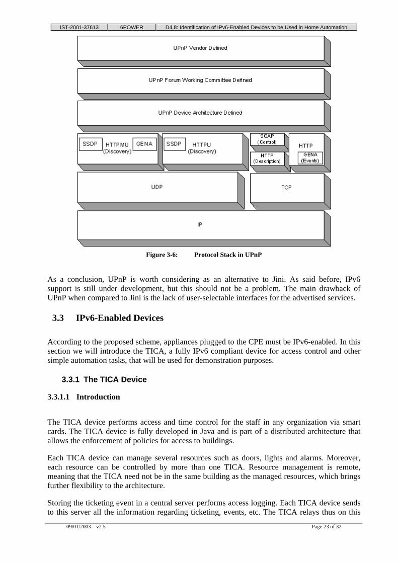
The TCP/IP networking protocol stack serves as the base on which the rest of the UPnP protocols are built. Also, HTTP is a core part of UPnP.
Simple Service Discovery Protocol (SSDP), built on HTTP, defines how control points can locate resources in the network and how devices can announce their availability.
Generic Event Notification Architecture (GENA) was defined to provide the ability to send and receive notifications using HTTP over TCP/IP and multicast UDP.
Simple Object Access Protocol (SOAP) defines the use of eXtensible Markup Language (XML) and HTTP to execute remote procedure calls. XML is a core part of UPnP used in device and service descriptions, control messages and event notification.
Every device must have a DHCP client, so the first time it is plugged into a network must search for a DHCP server and get an address. Once the device is attached to the network and addressed, it can advertise its services using SSDP. It will advertise a few specifics about the device or about its services.
IST-2001-37613 6POWER D4.8: Identification of IPv6-Enabled Devices to be Used in Home Automation
09/01/2003 – v2.5 Page 23 of 32
Figure 3-6: Protocol Stack in UPnP
As a conclusion, UPnP is worth considering as an alternative to Jini. As said before, IPv6 support is still under development, but this should not be a problem. The main drawback of UPnP when compared to Jini is the lack of user-selectable interfaces for the advertised services.
3.3 IPv6-Enabled Devices
According to the proposed scheme, appliances plugged to the CPE must be IPv6-enabled. In this section we will introduce the TICA, a fully IPv6 compliant device for access control and other simple automation tasks, that will be used for demonstration purposes.
3.3.1 The TICA Device
3.3.1.1 Introduction
The TICA device performs access and time control for the staff in any organization via smart cards. The TICA device is fully developed in Java and is part of a distributed architecture that allows the enforcement of policies for access to buildings.
Each TICA device can manage several resources such as doors, lights and alarms. Moreover, each resource can be controlled by more than one TICA. Resource management is remote, meaning that the TICA need not be in the same building as the managed resources, which brings further flexibility to the architecture.
Storing the ticketing event in a central server performs access logging. Each TICA device sends to this server all the information regarding ticketing, events, etc. The TICA relays thus on this
IST-2001-37613 6POWER D4.8: Identification of IPv6-Enabled Devices to be Used in Home Automation
09/01/2003 – v2.5 Page 24 of 32
central element in the organization, the server, which will record in a data base any events that may occur during access control: Entrance ticketing, exit ticketing, periodic status reports, error notifications, etc. By means of this server, the system administrator will know at any time about the status of the TICA devices, the managed resources and the system users. This server will feature a management application for defining the elements in the organization: Users, user smart cards, TICA devices and the resources managed by them.
The Figure 3-7 shows the distributed architecture just described.
Figure 3-7: The Distributed Architecture of the TICA Devices
As it can be seen, the TICA 1 controls “Door” and “Light” resources, which are in the same building in which this TICA is installed. Both the TICA 2 and the TICA 3 manage the alarm of the organization; in this case both the managed resource (“Alarm”) and each of the controlling TICAs are in separate buildings. Every TICA device sends ticking and error information to the central server, which is located in another building along with the database (which could also be in another building).
3.3.1.2 Components
The TICA includes the following external elements: • An LCD display for showing messages to the user. • A keyboard for user input, which is used to enter the PIN, choosing a menu option, etc. • A smart card reader, or a wireless reader for contact-less smart cards.
Internally, the TICA device features: • A Java microprocessor, which runs the access control program. • A device controller board connected to the reader the display, the keyboard and the Java
microprocessor, which includes in turn: A beeper for emitting acoustic signals, four digital inputs (for reading external signals such as a pulse indicating that a door has been closed), and four digital outputs (used to send pulses to the devices controlled by the TICA, such as an alarm, a light, etc.).
IST-2001-37613 6POWER D4.8: Identification of IPv6-Enabled Devices to be Used in Home Automation
09/01/2003 – v2.5 Page 25 of 32
3.3.1.3 Features
The TICA device features the following services: • Distributed management of access rights: The rights granted to each user are stored
locally, so that a distributed administration of all the TICA devices can be done. The access policy is specified locally in each TICA, so that each TICA can behave differently according to the organization needs. For example, it is really simple to set up the system to allow the entrance to a building only if it has been left before with an exit ticket.
• Scalability: The proposed system is scalable and customizable to fit the needs of the organization where it is going to be deployed. It supports any number of TICAs, each of them being able to manage any kind of resource (alarms, lights, doors …) either individually or in a shared fashion.
• JavaTICA Desktop: A TICA device can be simulated with a PC, which allows remote ticketing from a handheld device.
• Contact-less TICA: The contact-less TICA works exactly the same way as the normal TICA, but in this case there is no need to insert the smart card, it is enough to approach it slightly. The main advantage of a contact-less TICA is that ticketing becomes quicker and more comfortable. Since the smart card does not need to be inserted, it is possible to perform the ticketing without even having to stop in front of the TICA. If the user has more than one contact-less smart card for different applications, he or she needs not to bother to choose the right one, since the reader can do this automatically. The absence of metallic contacts allows for the whole card to be made of plastic, which prevents corrosion and scuffing.
• Remote access: Every TICA device can be remotely controlled. Jini is used for advertising the presence and services of a TICA, which can then be contacted and commanded; this enables an end-to-end access for remote automation. Authentication in this mode of operation is password based (SSH secured), although certificates could also be used, either by using a smart card reader or pre-installing them on the computer.
3.3.1.4 Operation
After the user has inserted the smart card in the TICA, PIN validation will follow and, optionally, a menu will show up to select the ticketing type. The image on Figure 3-8 depicts this operation.
If everything runs smoothly, the ticketing is sent to the server and the user rights are retrieved locally. If the user is allowed to carry out the requested operation, the TICA will perform the device activations needed for it.
Should any error occur while storing the ticketing in the server, the ticketing will remain stored locally and, once the problem is solved, it will be sent to the server.
IST-2001-37613 6POWER D4.8: Identification of IPv6-Enabled Devices to be Used in Home Automation
09/01/2003 – v2.5 Page 26 of 32
Figure 3-8: TICA Operation with a Conventional Smart Card
In the case of a contact-less TICA, operation is alike. The only different is that the smart card must not be inserted prior user interaction. When a user of a contact-less smart card wishes to access a TICA-controlled facility, he or she will only have to approach the card to the reader and the requested operation (open door, record access, etc) will be carried out automatically, as seen in the Figure 3-9.
Figure 3-9: TICA Operation with a Contact-less Smart Card
As said before, TICA devices are also remotely addressable. Each TICA uses the Jini technology to advertise itself by offering a remote interface. A Jini client can learn about the TICA devices present in a network, retrieve the remote interface and use it to command the TICA remotely. Thus, the TICA can be considered an end-to-end remote automation device.
3.3.1.5 Requirements
To deploy a TICA based system it is required: • For the TICA device itself, just a network link between it and the server, and a power
source.
IST-2001-37613 6POWER D4.8: Identification of IPv6-Enabled Devices to be Used in Home Automation
09/01/2003 – v2.5 Page 27 of 32
• For the server, a computer with any operating system with Java 1.2 or later, which will run the server and management application, and a data base management system which may be running on the same machine or on another.
3.4 Non-IPv6 Devices
The proposed setup showed an aggregator device that could translate third party automation protocols (X10, EIB …) into power line, allowing simple non-IPv6 devices such as lights to be end-to-end controlled. The next section introduces OSGi, the proposed technology for performing this aggregation and integration.
3.4.1 The Open Services Gateway initiative
The Open Services Gateway initiative (OSGi) [OSGi] is a non-profit corporation organized in the USA, and supported by more than 70 companies worldwide, that is defining a set of APIs and providing a sample implementation of services gateway architecture. The services gateway is an embedded server that is inserted into the network to connect the external Internet to internal clients. Service providers will be delivering just-in-time value added services to this services gateway and this gateway will provide a service distribution, integration and management point, such as in a SOHO/ROBO (Small Office/Home Office and Remote Office/Branch Office) or residence.
The OSGi framework and specification facilitates the installation and operation of multiple services on a single services gateway (set-top-box, cable or DSL modem, PC, Web phone, automotive, multimedia gateway or dedicated residential gateway). The specifications delineate Application Programming Interface (API) standards for a gateway platform execution environment. Services gateways must support these APIs in order to conform to the OSGi specification. The APIs address service cradle-to-grave life cycle management, inter-service dependencies, data management, device management, client access, resource management and security. Using these APIs, end-users can load network-based services on demand from the service provider while the gateway manages the installation, versioning and configuration of these services.
Once present in an Open Services Gateway, these services may be accessed by all connected devices and networks in the home, small office and remote/mobile locations. The gateway consolidates and manages voice, data, control, Internet and multimedia IPv6 communications, and provides a framework for interoperability between service providers, network operators, service gateway manufacturers and home appliance manufacturers.
As said before, a services gateway can be a set-top-box (STB), cable or DSL modem, PC, web phone, or a dedicated automotive, multimedia, or residential gateway.
In the past, service providers operated exclusively in their respective domains, for instance telephony or data networking, or cable services, or entertainment or mobile commerce or energy management and telematics. With the emergence of the services gateway, the lines between these various entities have blurred.
Today, multiple services (i.e. traditional telephony, Internet access, video and other on-demand content, interactive entertainment, mobile commerce, telemetry and energy management, home appliance control, etc.) can be bundled and managed by any of the traditional service providers. These services are offered via the Internet and various last mile broadband connections to the home, small office, and or to mobile/remote devices.
IST-2001-37613 6POWER D4.8: Identification of IPv6-Enabled Devices to be Used in Home Automation
09/01/2003 – v2.5 Page 28 of 32
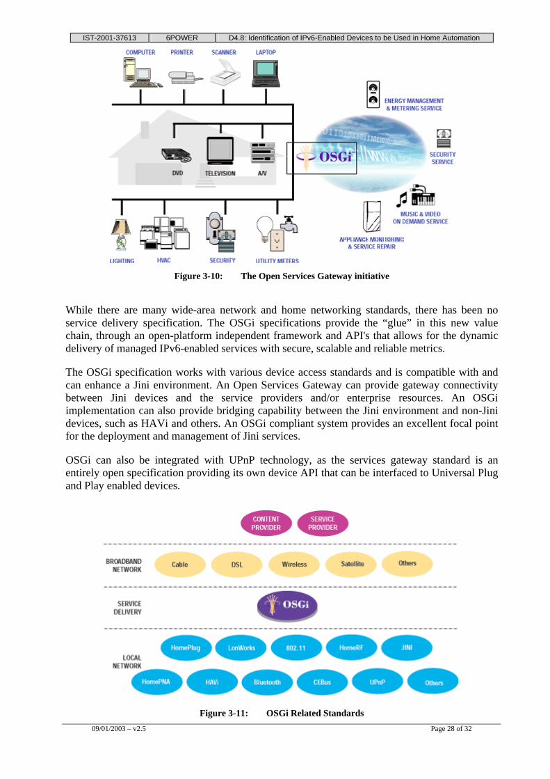
Figure 3-10: The Open Services Gateway initiative
While there are many wide-area network and home networking standards, there has been no service delivery specification. The OSGi specifications provide the “glue” in this new value chain, through an open-platform independent framework and API's that allows for the dynamic delivery of managed IPv6-enabled services with secure, scalable and reliable metrics.
The OSGi specification works with various device access standards and is compatible with and can enhance a Jini environment. An Open Services Gateway can provide gateway connectivity between Jini devices and the service providers and/or enterprise resources. An OSGi implementation can also provide bridging capability between the Jini environment and non-Jini devices, such as HAVi and others. An OSGi compliant system provides an excellent focal point for the deployment and management of Jini services.
OSGi can also be integrated with UPnP technology, as the services gateway standard is an entirely open specification providing its own device API that can be interfaced to Universal Plug and Play enabled devices.
Figure 3-11: OSGi Related Standards
IST-2001-37613 6POWER D4.8: Identification of IPv6-Enabled Devices to be Used in Home Automation
09/01/2003 – v2.5 Page 29 of 32
The OSGi framework is designed for creating extensible services using the Java programming language, thus being ready for IPv6. To take best advantage, developers should design an application as a set of bundles that contain services, with each service implementing a segment of the overall functionality. These bundles are then downloaded on demand by the target device. For example, a text editing application designed this way may rely on a spell-checking service. The editor would instruct the framework to download a spell-checker for it to use.
The key entities in the framework are: • Services: The Java classes that perform certain functionality, usually written with
interface and its implementation separated. • Bundles: The functional and deployment unit for shipping services.
A service is a self-contained component, accessible via a defined service interface. In the OSGi model, an application is built around a set of cooperating services: It can extend its functionality at runtime by requesting more services, which it requires. The framework maintains a set of mappings from services to their implementations and has a simple query mechanism (LDAP based syntax) that enables an installed service to request and use the available services. The framework manages the dependencies among services.
A developer defines a service as an interface and provides its implementation. Then he can register the service with the framework (registering a service is also called publishing it). When a service is registered, it can be given a set of properties (name/value pairs) to enable a sophisticated retrieval based on LDAP attribute comparisons.
After a service is published, other services can use it to accomplish their tasks; they look up the service from the framework with a search filter, and will get back the matching service references. The service reference can then be used to get a Java object that implements the desired service.
• To be available to the framework, a service implementation must be packaged. Service implementations are packaged into bundles. A bundle is a JAR file that: Contains the resources implementing zero or more services. These resources may be class files for the
IST-2001-37613 6POWER D4.8: Identification of IPv6-Enabled Devices to be Used in Home Automation
09/01/2003 – v2.5 Page 30 of 32
Java programming language, as well as any other data (such as HTML help files, icons, and so on).
• Contains a Manifest file with headers specifying various parameters so that the Framework can correctly install and activate the bundle. These parameters include what Java packages this bundle provides, what packages it needs, how to locate its bundle activator, and so on.
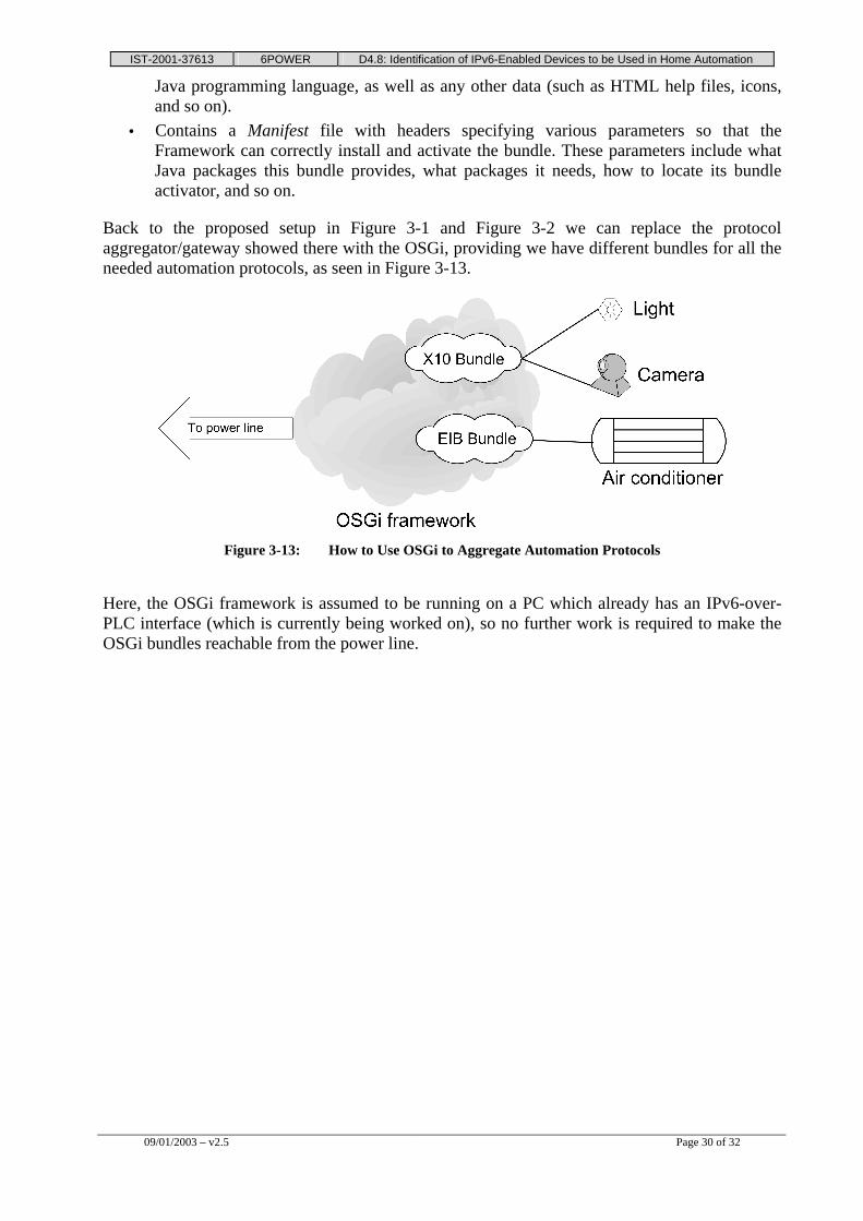
Back to the proposed setup in Figure 3-1 and Figure 3-2 we can replace the protocol aggregator/gateway showed there with the OSGi, providing we have different bundles for all the needed automation protocols, as seen in Figure 3-13.
Figure 3-13: How to Use OSGi to Aggregate Automation Protocols
Here, the OSGi framework is assumed to be running on a PC which already has an IPv6-over-PLC interface (which is currently being worked on), so no further work is required to make the OSGi bundles reachable from the power line.
IST-2001-37613 6POWER D4.8: Identification of IPv6-Enabled Devices to be Used in Home Automation
09/01/2003 – v2.5 Page 31 of 32
4. SUMMARY AND CONCLUSIONS
Current technologies for home automation have quite similar automation capabilities, being the main differences the way devices are addressed, the allowed physical media and the maximum available bandwidth.
The most common applications for the reviewed automation technologies are: • Lights (on, off, dim, bright). • Ventilation, air conditioning and temperature. • Switching devices on and off (radio, TV, ...). • Irrigation systems. • Blinds, shutters and curtains. • Access and security. • Surveillance and alarms. • Energy and load management.
As for bandwidth, the minimum is X10's 50 bps or 60 bps. The most common speeds range from 2,400 bps to 4,800 bps; there are some higher possibilities but they are uncommon: 9,600 bps or 64 Kbps only with EHS (twisted pair based) and 10 Mbps only with EIB.net (Ethernet based).
The conclusion that can be drawn is that none of the analyzed technologies offers a true end-to-end, high bandwidth access to the devices at home. The PLC-based solution we are proposing here (to use IPv6 with QoS over power line for reaching home equipment from the Internet) proves thus the best mean for offering this valuable service.
Within the IPv6-over-PLC solution, a set of different automation protocols can also be used, by means of the OSGi framework to achieve interoperability among them and integrate them in the IPv6 network. This is useful for small devices unable to host a IPv6 or PLC interface (lights, heaters, …) which are better managed by using simpler protocols like X10.
Managed devices need to advertise their interfaces; there are two technologies for doing this that can be integrated in the OSGi as well: Jini from Sun Microsystems and UPnP from Microsoft. While the first one allows the vendor to define whatever interface is needed, interfaces in UPnP must always extend the functionalities of some predefined type of interface (printer, TV, …). This makes Jini a slightly more flexible alternative; plus, the implementation of new services in Jini is easier than in UPnP. On the other hand, UPnP is more widely supported by vendors.
Summing up, the devices to be in home automation can be divided into: • IPv6 capable devices, such as a computer with a PLC interface, which can be directly
integrated within the PLC network. • Non-IPv6 devices, such as lights or blinds, which are better managed via simpler
protocols like X10, and can be integrated in the PLC network through the services gateway (OSGi).
As an example of the first type of devices, the TICA has been introduced. It is an IPv6 compliant device capable of performing access control and simple automation tasks, and can be remotely controlled.
IST-2001-37613 6POWER D4.8: Identification of IPv6-Enabled Devices to be Used in Home Automation