Moe Phyu Hlaing, Khin Ye Lwin Division of Atomic Energy Department of Research and Innovation Ministry of Education, Myanmar Identification of the Internal Condition of Crude Oil Distillation Unit Using Gamma Column Scanning Technique ID-34, B13-05
Transcript
Moe Phyu Hlaing, Khin Ye Lwin Division of Atomic Energy
Department of Research and Innovation Ministry of Education, Myanmar
Identification of the Internal Condition of Crude Oil
Distillation Unit Using Gamma Column Scanning Technique
ID-34, B13-05
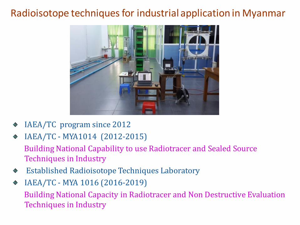
Radioisotope techniques for industrial application in Myanmar
IAEA/TC program since 2012
IAEA/TC - MYA1014 (2012-2015)
Building National Capability to use Radiotracer and Sealed Source Techniques in Industry
Established Radioisotope Techniques Laboratory
IAEA/TC - MYA 1016 (2016-2019)
Building National Capacity in Radiotracer and Non Destructive Evaluation Techniques in Industry
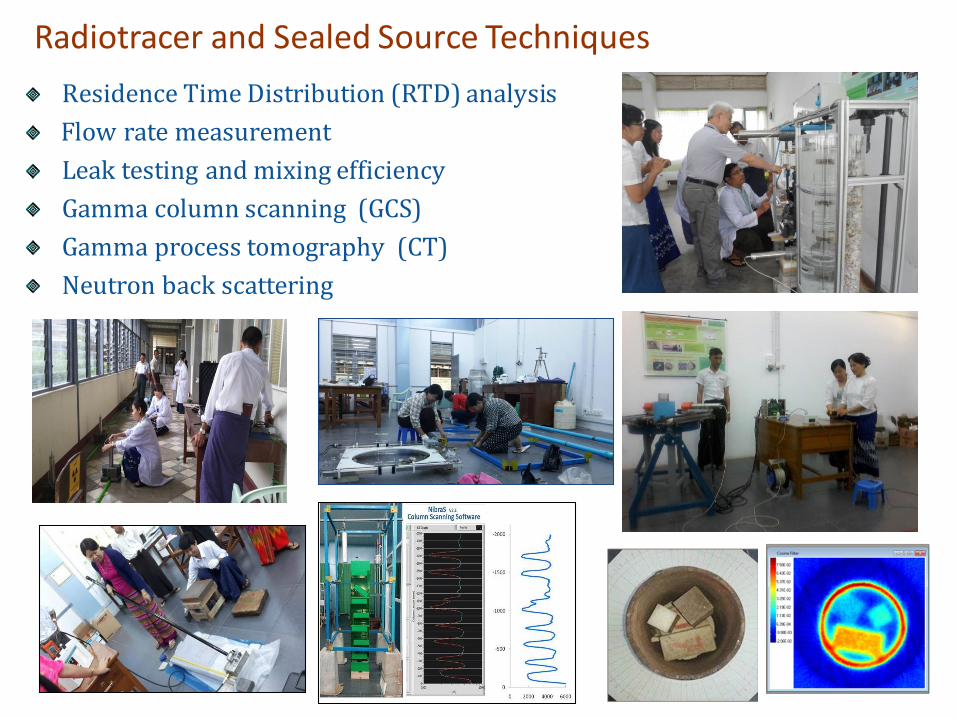
Residence Time Distribution (RTD) analysis
Flow rate measurement
Leak testing and mixing efficiency
Gamma column scanning (GCS)
Gamma process tomography (CT)
Neutron back scattering
Radiotracer and Sealed Source Techniques
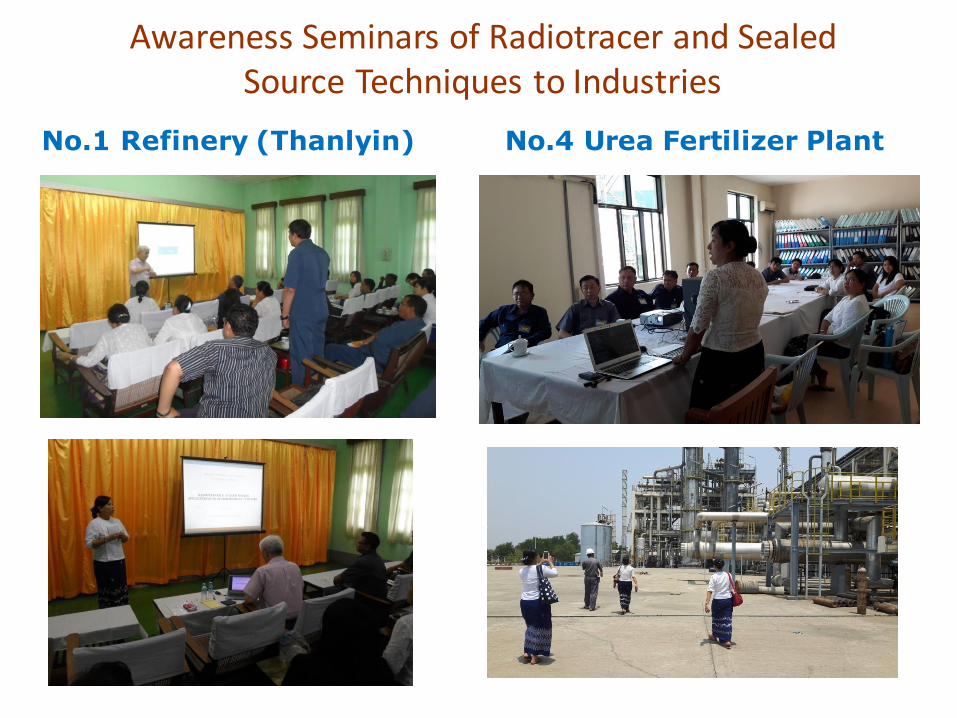
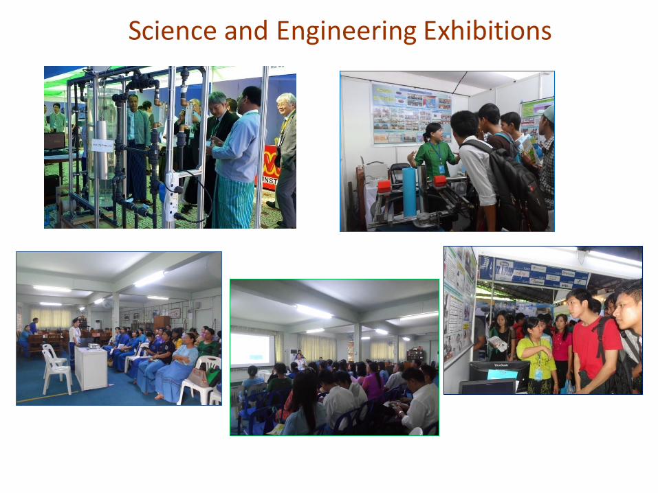
Awareness Seminars of Radiotracer and Sealed Source Techniques to Industries
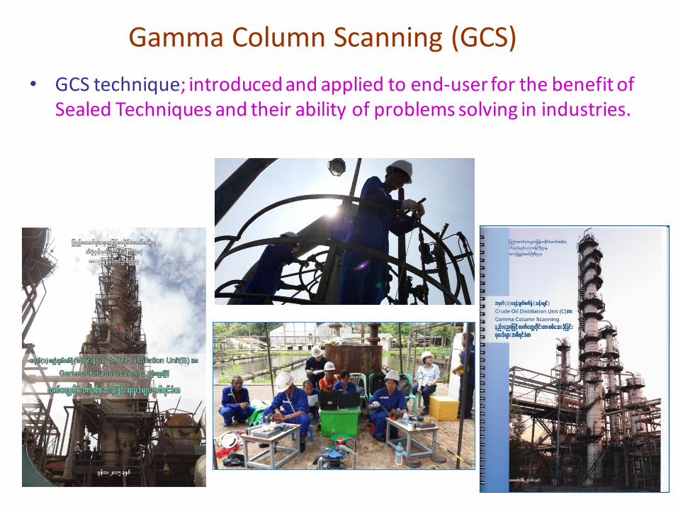
• GCS technique; introduced and applied to end-user for the benefit of Sealed Techniques and their ability of problems solving in industries.
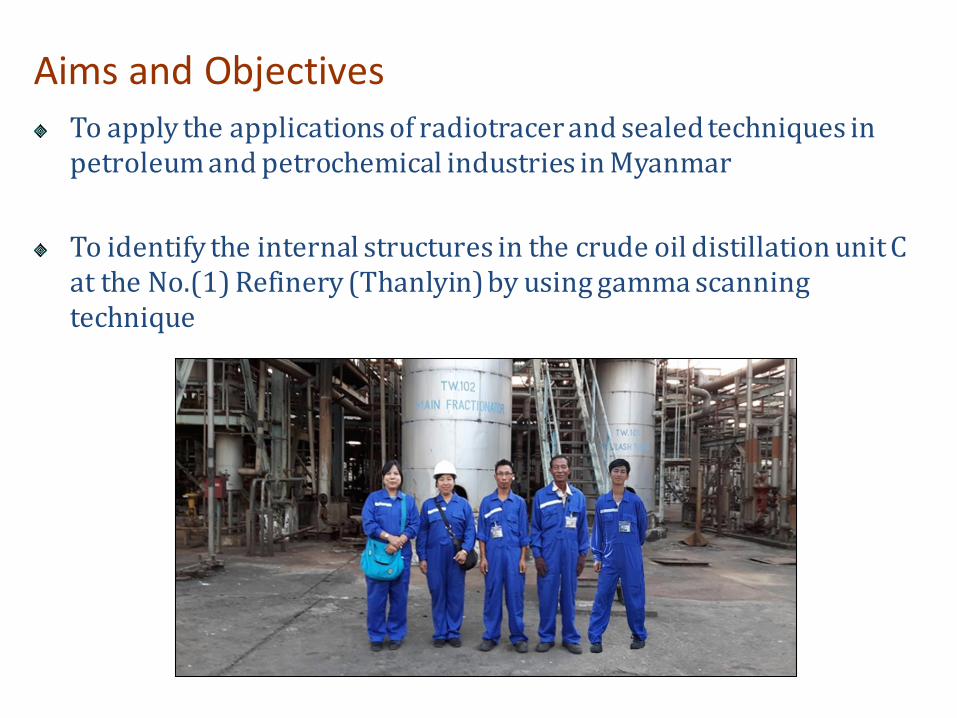
To apply the applications of radiotracer and sealed techniques in petroleum and petrochemical industries in Myanmar
To identify the internal structures in the crude oil distillation unit C at the No.(1) Refinery (Thanlyin) by using gamma scanning technique
Aims and Objectives
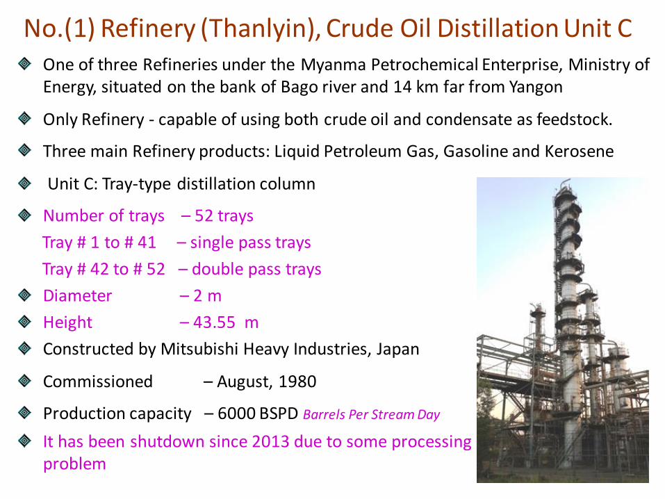
No.(1) Refinery (Thanlyin), Crude Oil Distillation Unit C One of three Refineries under the Myanma Petrochemical Enterprise, Ministry of Energy, situated on the bank of Bago river and 14 km far from Yangon
Only Refinery - capable of using both crude oil and condensate as feedstock.
Three main Refinery products: Liquid Petroleum Gas, Gasoline and Kerosene
Unit C: Tray-type distillation column
Number of trays – 52 trays
Tray # 1 to # 41 – single pass trays
Tray # 42 to # 52 – double pass trays
Diameter – 2 m
Height – 43.55 m
Constructed by Mitsubishi Heavy Industries, Japan
Commissioned – August, 1980
Production capacity – 6000 BSPD Barrels Per Stream Day
It has been shutdown since 2013 due to some processing problem
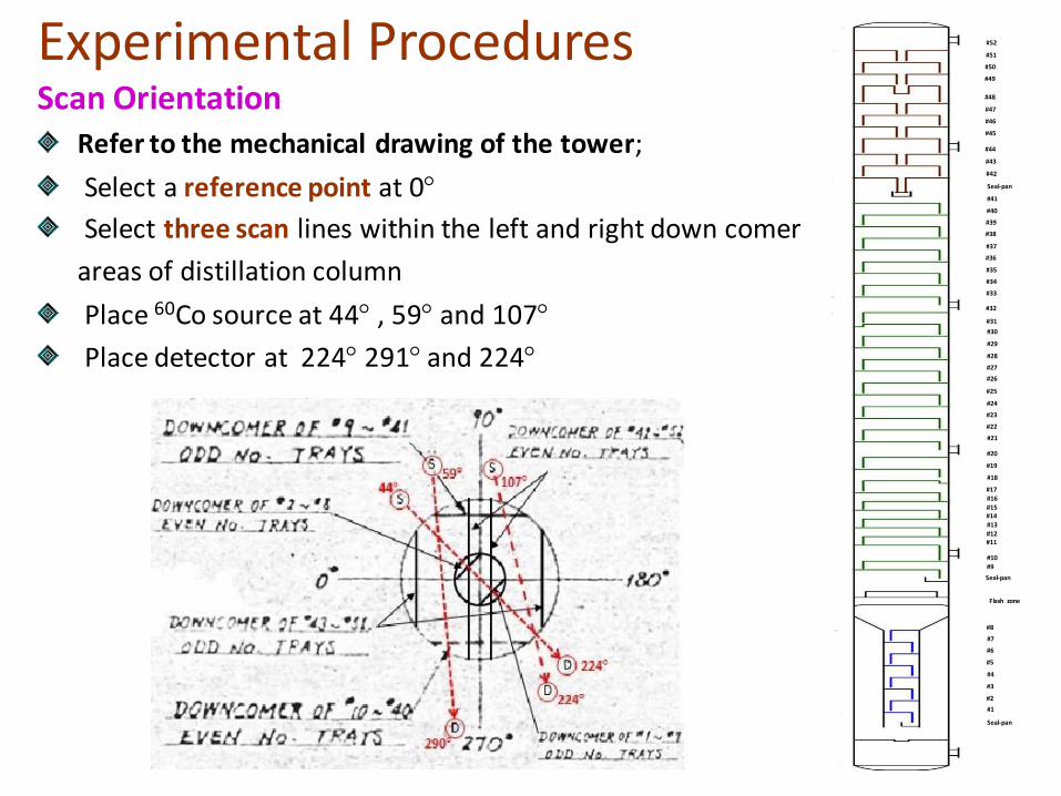
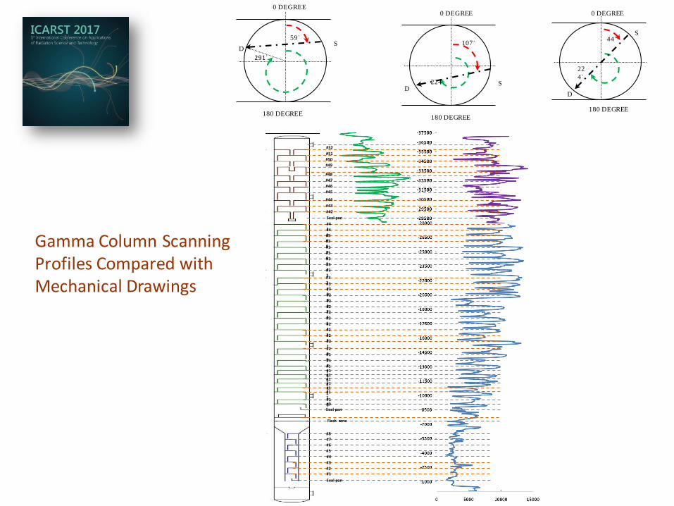
Experimental Procedures Scan Orientation
Refer to the mechanical drawing of the tower;
Select a reference point at 0
Select three scan lines within the left and right down comer
areas of distillation column
Place 60Co source at 44 , 59 and 107
Place detector at 224 291 and 224
#41
#40
#39
#38
#37
#36
#35
#34
#33
#32
#31
#30
#29
#28
#27
#26
#25
#24
#23
#22
#21
#20
#19
#18
#17
#16
#15
#14
#13
#12
#11
#10
#9
Seal-pan
#8
#7
#6
#5
#4
#3
#2
#1
Seal-pan
Flash zone
#52
#51
#50
#49
#48
#47
#46
#45
#44
#43
#42
Seal-pan
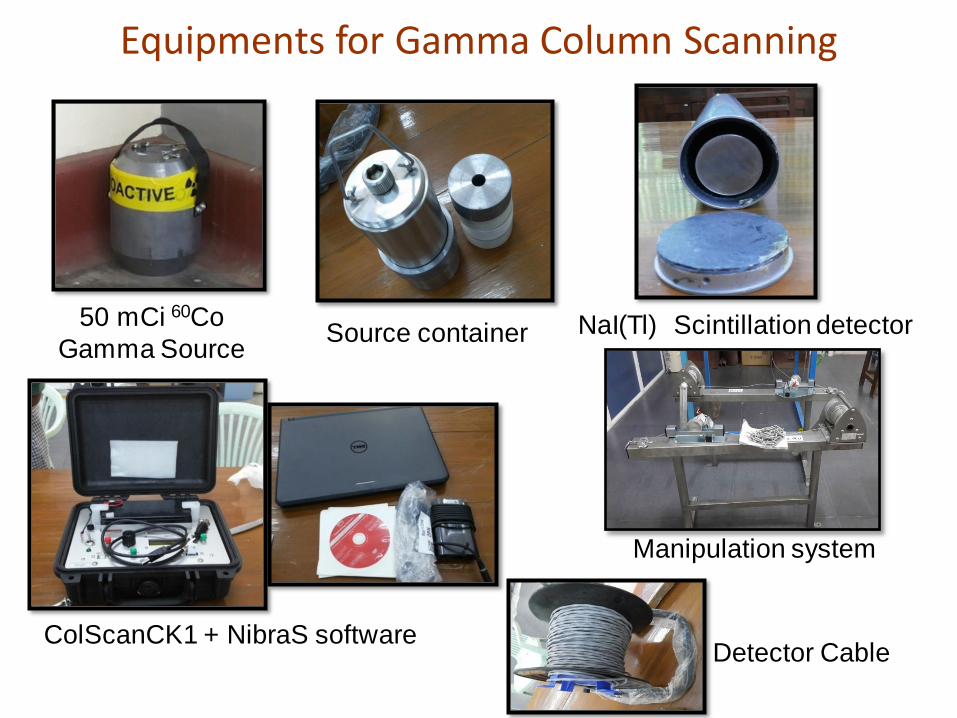
Equipments for Gamma Column Scanning
NaI(Tl) Scintillation detector 50 mCi 60Co
Gamma Source Source container
Manipulation system
ColScanCK1 + NibraS software Detector Cable
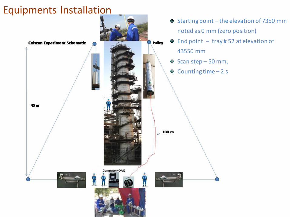
Equipments Installation Starting point – the elevation of 7350 mm
noted as 0 mm (zero position)
End point – tray # 52 at elevation of
43550 mm
Scan step – 50 mm,
Counting time – 2 s
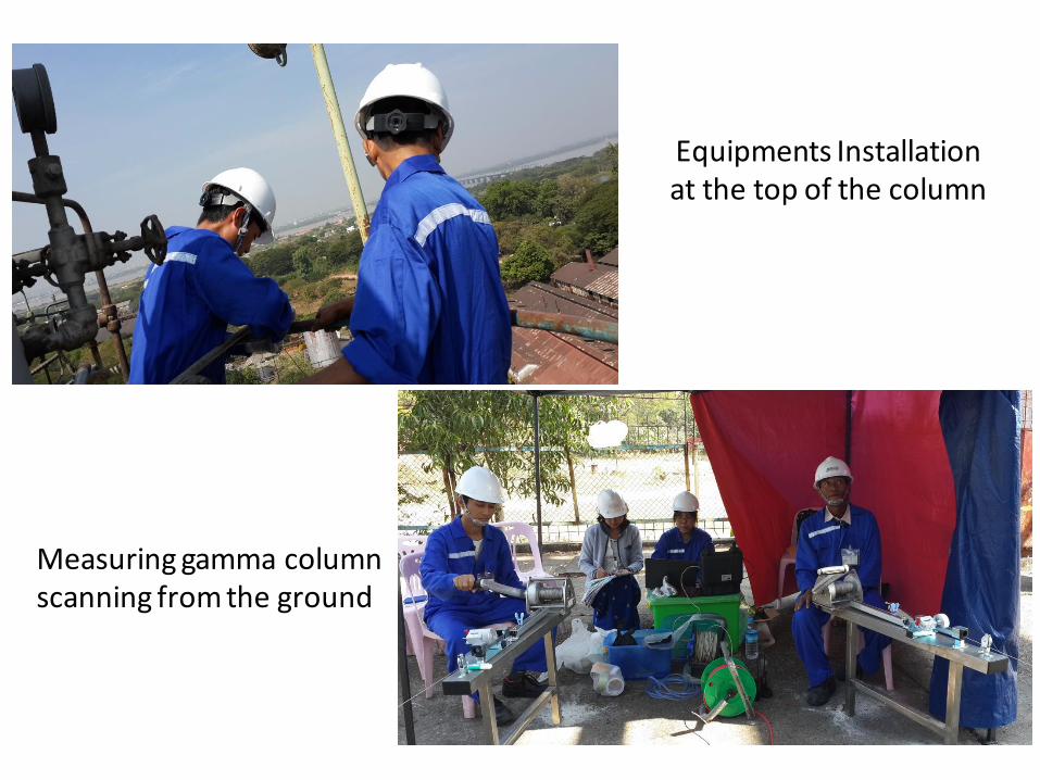
Equipments Installation at the top of the column
Measuring gamma column scanning from the ground
DISTANCE
TIME
SHIELD
SOURCE
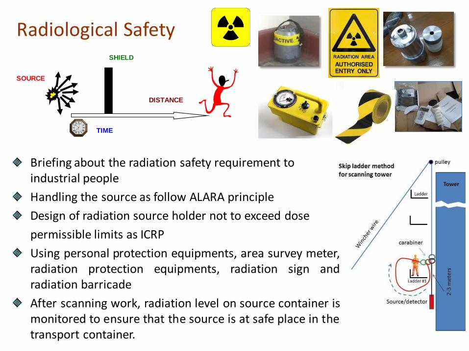
Radiological Safety
Briefing about the radiation safety requirement to industrial people
Handling the source as follow ALARA principle
Design of radiation source holder not to exceed dose
permissible limits as ICRP
Using personal protection equipments, area survey meter, radiation protection equipments, radiation sign and radiation barricade
After scanning work, radiation level on source container is monitored to ensure that the source is at safe place in the transport container.
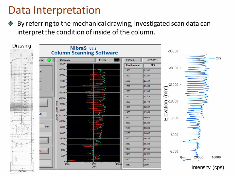
Data Interpretation By referring to the mechanical drawing, investigated scan data can interpret the condition of inside of the column.
-33000
-28000
-23000
-18000
-13000
-8000
-3000
0 20000 40000
CPS
Intensity (cps) E
leva
tion (
mm
)
Drawing
RESULT AND DISCUSSION
S
0 DEGREE
D
44˙
224
˙
180 DEGREE
S
0 DEGREE
D
44 ̇
224 ̇
180 DEGREE
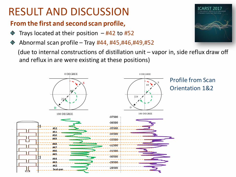
From the first and second scan profile,
Trays located at their position – #42 to #52
Abnormal scan profile – Tray #44, #45,#46,#49,#52
(due to internal constructions of distillation unit – vapor in, side reflux draw off and reflux in are were existing at these positions)
#52
#51
#50 #49
#48
#47
#46
#45
#44
#43
#42
Seal-pan
Profile from Scan Orientation 1&2
RESULT AND DISCUSSION
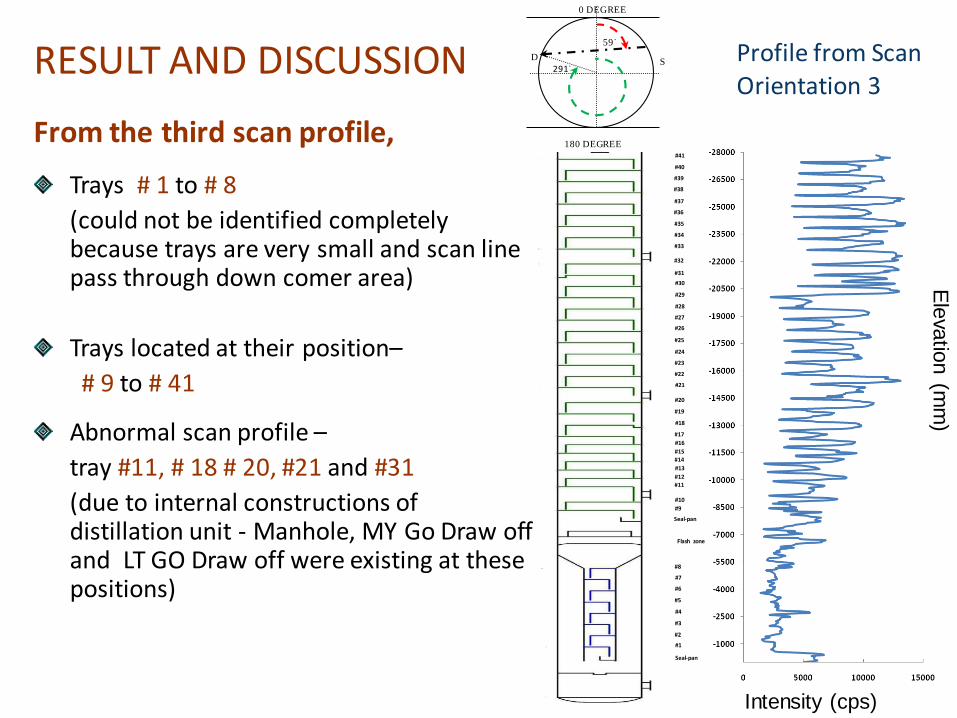
From the third scan profile,
Trays # 1 to # 8
(could not be identified completely because trays are very small and scan line pass through down comer area)
Trays located at their position–
# 9 to # 41
Abnormal scan profile –
tray #11, # 18 # 20, #21 and #31
(due to internal constructions of distillation unit - Manhole, MY Go Draw off and LT GO Draw off were existing at these positions)
Seal-pan Gamma Column Scanning Profiles Compared with Mechanical Drawings
CONCLUSION
Gamma column scanning technique was utilized to identify the mechanical in trayed column of Crude Oil Distillation Unit C at the No. (1) Refinery (Thanlyin), Yangon, Myanmar.
It was challenged to scan because the space between insulator and ladder is very narrow, in some places detector and source were passed the ladder with considering of radiation safety aspect.
Local team had capability and confident to conduct column scanning experiment in industrial scale. Local team could identified # 9 to # 52 trays located at their position.
Future suggestion – To keep a systematic and complete record of column operating conditions, on-line investigation should be implemented during operation.