JOURNAL Of NUCLEAR And Related TECHNOLOGIES, Volume 11, No. 2, December 2014. DEVELOPMENT OF FPGA-BASED READOUT CONTROLLER IN A CALORIMETER OF AN E-P COLLIDER Faridah Mohamad Idris1-2, Wan Ahmad Tajuddin Wan Abdullah2, Zainol Abidin Ibrahim2, Peter Goettlicher3 -Malaysian Nuclear Agency, Bangi, f.3000, Kajang. Selangor, Malaysia. 'Physics Department, Faculty of Science, University of Malaya, 50603 Kuala Lumpur, Malaysia. s Deutsch.es Electronen Synchrotron (DESY), Hamburg, Germany. e-mail: [email protected]. my ABSTRACT In complex controlling algorithm, such as in high energy physics experiment, Programmable Gate Array (FPGA) based readout controller may offer the most convenient method for its allows for a trigger improvement and troubleshooting purposes with minimal costing. In case of the readout controller of the calorimeter of the ZEUS detector at Hadron-Electron Ring Accelerator (HERA), the analogue modules i.e. table, pipeline, buffer and format controls, were converted into a single FPGA-based controller, to study trigger sequence between the pipeline and the bujfer that have cause unwanted data being carried into the data tables despite the fast clear signal trigger. Hardware descriptive language (HDL) Verilog was used to code the analogue controller into FPGA-based, and later simulated on Quartus II using a single Altera Cyclone configuration. We also include the first version of the hardware interface board with a single FPGA chip in the middle of the board. ABSTRAK Dalam algoritma pengawalan yang kompleks, seperti di eksperimen fizik tenaga tinggi, Programmable Gate Array (FPGA ) berpangkalan pengawal baca keluar mungkin menawarkan paling ban/yak kaedah mudah untuknya membenarkan peningkatan picu. dan tujuan-tujuan merumus masalah dengan pengekosan minimum. Jika pengawal baca keluar kalorimeter pengesan ZEUS di Hadron Electron Ring Accelerator, modui-modul analog iaitu meja, saluran paip, penimbal. dan kawalan format, telah ditukar ke dalam satu pengawal berasaskan FPGA, untuk belajar jujukan picu. antara saluran paip dan penimbal yang mempunyai data tidak dikehendaki punca dibawa ke dalam jadual data walaupun picu. isyarat jelas yang cepat. Bahasa deskriptif perkakasan Verilog digu.nakan untu.k kod pengawal analog ke dalam FPGA berpangkalan, dan kemudian dibuat-buat atas Quartus II menggunakan satu. tatarajah Altera Cyclone. Kami juga merangkumi versi pertama lembaga antara mu.ka perkakasan dengan satu. cip FPGA di tengah-tengah papan litar. Keywords: readout controller, FPGA-based, single on chip, hardware interface 17
Transcript
JOURNAL Of NUCLEAR And Related TECHNOLOGIES, Volume 11, No. 2, December 2014.
DEVELOPMENT OF FPGA-BASED READOUT
CONTROLLER IN A CALORIMETER OF AN E-PCOLLIDER
Faridah Mohamad Idris1-2, Wan Ahmad Tajuddin Wan Abdullah2, ZainolAbidin Ibrahim2, Peter Goettlicher3
-Malaysian Nuclear Agency, Bangi, f.3000, Kajang. Selangor, Malaysia.
'Physics Department, Faculty of Science, University of Malaya, 50603 Kuala Lumpur,Malaysia.
In complex controlling algorithm, such as in high energy physics experiment, Programmable
Gate Array (FPGA) based readout controller may offer the most convenient method for its
allows for a trigger improvement and troubleshooting purposes with minimal costing. In case ofthe readout controller of the calorimeter of the ZEUS detector at Hadron-Electron Ring
Accelerator (HERA), the analogue modules i.e. table, pipeline, buffer and format controls,
were converted into a single FPGA-based controller, to study trigger sequence between the
pipeline and the bujfer that have cause unwanted data being carried into the data tables despite
the fast clear signal trigger. Hardware descriptive language (HDL) Verilog was used to code the
analogue controller into FPGA-based, and later simulated on Quartus IIusing a single Altera
Cyclone configuration. We also include the first version of the hardware interface board with a
single FPGA chip in the middle of the board.
ABSTRAK
Dalam algoritma pengawalan yang kompleks, seperti di eksperimen fizik tenaga tinggi,
Programmable Gate Array (FPGA ) berpangkalan pengawal baca keluar mungkin menawarkan
paling ban/yak kaedah mudah untuknya membenarkan peningkatan picu. dan tujuan-tujuan
merumus masalah dengan pengekosan minimum. Jika pengawal baca keluar kalorimeter
pengesan ZEUS di Hadron Electron Ring Accelerator, modui-modul analog iaitu meja, saluran
paip, penimbal. dan kawalan format, telah ditukar ke dalam satu pengawal berasaskan FPGA,
untuk belajar jujukan picu. antara saluran paip dan penimbal yang mempunyai data tidak
dikehendaki punca dibawa ke dalam jadual data walaupun picu. isyarat jelas yang cepat. Bahasa
deskriptif perkakasan Verilog digu.nakan untu.k kod pengawal analog ke dalam FPGA
berpangkalan, dan kemudian dibuat-buat atas Quartus IImenggunakan satu. tatarajah Altera
Cyclone. Kami juga merangkumi versi pertama lembaga antara mu.ka perkakasan dengan satu.
cip FPGA di tengah-tengah papan litar.
Keywords: readout controller, FPGA-based, single on chip, hardware interface
17
JOURNAL Of NUCLEAR And Related TECHNOLOGIES, Volume 11, No. 2, December 2014.
INTRODUCTION
In high energy physics data taking, the Programmable Gate Array (FPGA)-based readout controllermay offer the best replacement strategy in the detector survival (CMS UG-TP-1, 2010). This is
especially pertinent when the readout controller involves a large amount of data-taking at a fast rate,
and requires complex controlling algorithm (Altera Corporation, 2011). Single-on-chip FPGA-basedcontroller allows for a trigger improvement and troubleshooting purposes, as well easier for maintenance
when design as disposable parts and components.
The analogue readout controller of the former ZEUS detector at HERA (Hadron-Electron RingAccelerator) was converted into FPGA format to study the trigger sequence between the pipeline andbuffer modules that caused the data from physics event which did not belong to the bunch crossing of
the pipeline, to be carried into the chain of events - these data should have been aborted when the fastclear signal (FCLR) was triggered, but were still added into the data tables. In case of an active FCLR,this data anomaly could inhibit the efficiency of the data-taking of the readout controller (P.
Goettlicher, 2015).
In this paper, we described how the analogue modules of the readout control (ROC) of the calorimeterof the ZEUS detector were converted into the FPGA controller that accommodated more than 140
signals into a single FPGA module. The FPGA-based ROC was later used to demonstratesynchronization sequence between accept (ACT) and abort (ABT) signals between the pipeline andbuffer modules that might have caused failure of the aborted data by the buffer, resulting in redundantdata being carried into the data chain.
Figure 1. Schematic diagram of the calorimeter (CAL) read-outcontrol (ROC) of ZEUS detector with 96ns HERA clock
for synchronization. See Table 1for parameters definition
18
JOURNAL Of NUCLEAR And Related TECHNOLOGIES, Volume 11, No. 2, December 2014.
THEROC MODULES FUNCTION
The controlling readout modules such as in the former ZEUS detector gave a typical example of how thereadout controller in a particle collider operated, and might give an insight on the overall mechanism ofthe readout controller in a particle collider.
Figure 1 shows the readout analog controlling modules i.e. the table, pipeline, buffer, format andgenerator in the calorimeter of the ZEUS detector. The data taking during the electron-proton collisionin the high energy physics experiments were synchronized by a 96 ns or 10MHz HERA clock, using a
24-bits serial data for online control.
Sub modules functioned as follows: the table module interfaced between the General First Level Trigger
(GFLT) and the calorimeter readout electronics and, preset the controlling bits of the readout; thepipeline module selected which particular cell out of 96 samples to trigger (B. Schmidke, 2009) duringthe data taking; the buffer kept the interim data received from the pipeline; the format controllercontrolled the timing for the digitization of the output; the pulse generator controlled test pulses duringdata taking and during various offline operation.
The controlling bits during online operation of the readout system were kept in the RAM unit of thetable module. The controlling bits included sample delay, number of sample, event types, output format,event type and online/offline mode. During an offline mode, a 16-bits serial data synchronized by a
10MHz clock was send the RAM unit via a 16-bits shift register to preset the controlling bits. The firstbit of the serial data would be pushed up to the 16th bit in the RAM and, was continued until the 16thbit of the serial data was in the register, before the system was put in online mode and ready data-taking (A. Caldwell et o.L, 1992).
THE INTEGRATION OF THE ROCIN FPGA MODE
By integrating the four sub-modules i.e. table, pipeline, buffer and format of the ROC of the calorimeterof the ZEUS detector, into a single FPGA-based controlling module, we demonstrated that a compact
ROC system was possible for use in a particle collider. In the following sections we described how theanalogue circuits and the logic block diagram of ROC of calorimeter of the ZEUS detector were
converted into an FPGA-based ROC.
The block diagram of the original circuits of the analogue controlling modules was used as basicsbuilding blocks to the FPGA-based controller. Each block building in the sub-module was convertedinto an equivalent FPGA block using Verilog. and later combined into working sub-module. This step
was repeated for each of the sub-module in the readout controller; all of the sub-modules were latercombined to form an FPGA-based readout controller and functioned as a whole unit. Figure 2 gives theflow of coding of the analogue controlling modules into the FPGA-based module.
19
JOURNAL Of NUCLEAR And Related TECHNOLOGIES, Volume 11, No. 2, December 2014.
Simulation of
ROC
using
Quartus
ROC
Hardwareimplementati
on on an
AlteraCyclone
Single Board,FPGA-based
ROCmodules:
tablecQ,pipec(),
bufferc(),format c( )
ROC Analoguemodules
(Block&CircuitDiagrams)
Table
Pipeline
Buffer
Coding with Veriloginto Small Verilog
Modules
e.g. Shift
register(8,16-bits)
multiplexers, -JK,RS flip-flops,
decoder, counter
divider etc.)
Figure 2. The analogue modules of readout control (ROC) of the ZEUS detector were codedinto single board, FPGA-based using Verilog, starting with basic blocks, later
combined to become the main controlling block before being simulated on
Quartus II.
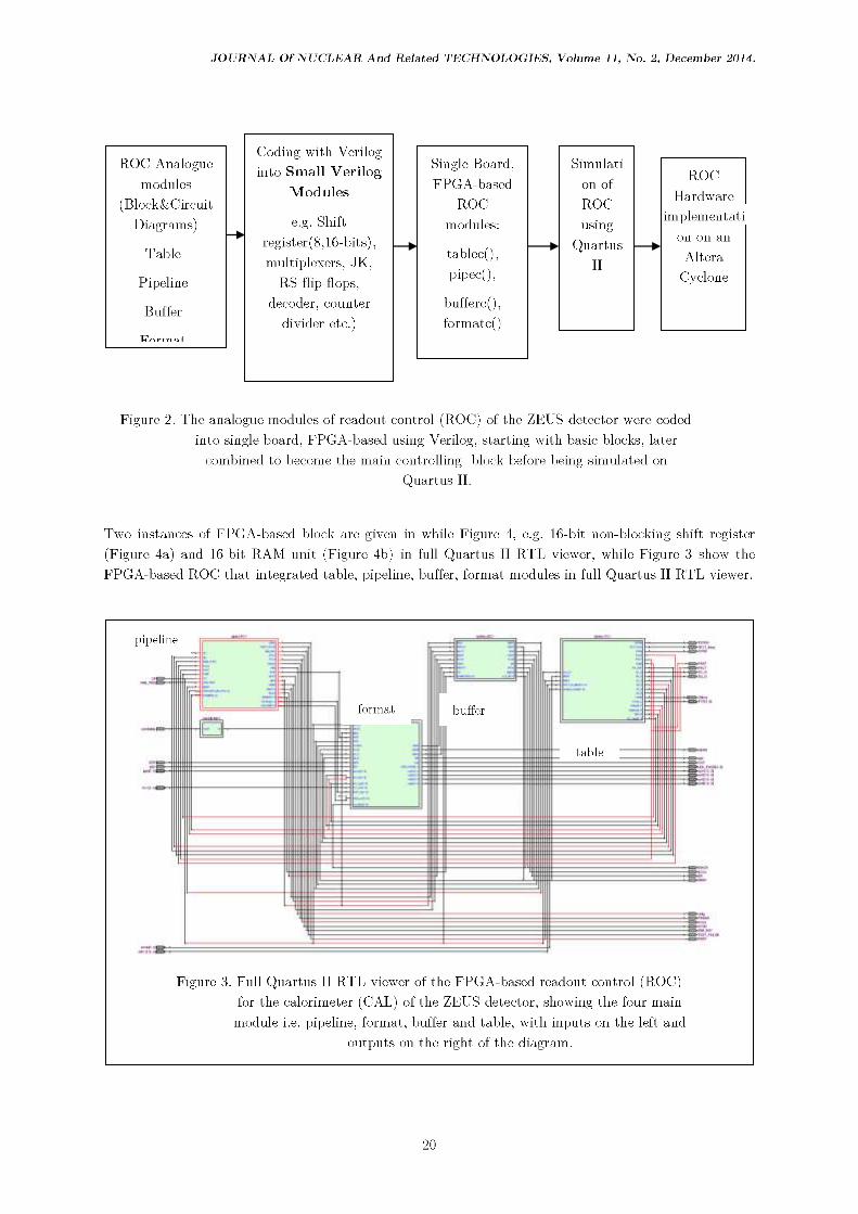
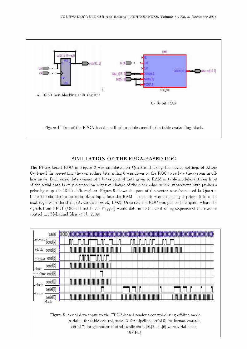
Two instances of FPGA-based block are given in while Figure 4, e.g. 16-bit non-blocking shift register
(Figure 4a) and 16-bit RAM unit (Figure 4b) in full Quartus IIRTL viewer, while Figure 3 show theFPGA-based ROC that integrated table, pipeline, buffer, format modules in full Quartus IIRTL viewer.
pipeline
format buffer
ta.hle
Figure 3. Full Quartus IIRTL viewer of the FPGA-based readout control (ROC)for the calorimeter (CAL) of the ZEL1S detector, showing the four main
module i.e. pipeline, format, buffer and table, with inputs on the left andoutputs on the right of the diagram.
20
JOURNAL Of NUCLEAR And Related TECHNOLOGIES, Volume 11, No. 2, December 2014.
(a) 16-bit non-blocking shift register
(b) 16-bit RAM
Figure 4. Two of the FPGA-based small sub-modules used in the table controlling block.
SIMULATION OF THE FPGA-BASED ROC
The FPGA-based ROC in Figure 3 was simulated on Quartus II using the device settings of AlteraCyclone I. In pre-setting the controlling bits, a flag 0 was given to the ROC to isolate the system in off¬
line mode. Each serial data consist of 4 bytes control data given to RAM in table module, with each bitof the serial data is only counted on negative change of the clock edge, where subsequent byte pushes a
prior byte up the 16-bit shift register. Figure 5 shows the part of the vector waveform used in QuartusII for the simulation for serial data input into the RAM - each bit was pushed by a prior bit into thenext register in the chain (A. Caldwell et al., 1992). Once set, the ROC was put on-line again, where thesignals from GFLT (Global First Level Trigger) would determine the controlling sequence of the readoutcontrol (F. Mohamad Idris et al., 2009).
generator
clock
format
clockpipeline
clock
table
clock
Figure 5. Serial data input to the FPGA-based readout control during off-line mode
(serial[0] for table control, serial[3] for pipeline, serial [-5] for format control,serial)?] for generator control; while serial[0],[2],[4]. [6] were serial clock
10MHz)
JOURNAL Of NUCLEAR And Related TECHNOLOGIES, Volume 11, No. 2, December 2014.
Figure 6a shows the output of the ROC simulation - when the pipeline accept data PACT is triggered,the pipeline busy PBSY and the pipeline read PREAD are triggered with PCLK temporarily disabled.Here, the buffer read is flagged 0 and the BC'LK is temporarily disabled. Figure 6(b) gives a closer lookat the sequence of pipeline and buffer triggers upon abort ABT signal by GFLT. On a negative edge of
ABT from GFLT, the pipeline abort PABT triggers and pipeline accept PACT is flagged down to 0.During the abort trigger, the buffer is still flagged 0 and only changes to 1about 0.07 ms later, resulting
in unused data being taken by the buffer instead of rejecting it.
Figure 6a. Output signals from the FPGA-based readout control
Figure 6b. A close-up of the FPGA-based readout control showing the abort ABT signal from thepipeline control. Global first level trigger during on-line operation with GFLT[12]: ACT=1 for Accept
data trigger, while GFLT[11]: ABT=1 for Abort data trigger (CP: HERA clock 10MHz).
22
JOURNAL Of NUCLEAR And Related TECHNOLOGIES, Volume 11, No. 2, December 2014.
Table 1 gives some of the output labels used the FPGA-based readout control (ROC) block, with the
output waveform as given in Figure 6 (a) and (b).
Table 1. Some of the input/output label from FPGA-based readout control (ROC) and theirstatus
Input label Input Status Flag Output label Output FlagStatus
HERA clock 96ns clock GFLT busy GFLT busy 1
(CP)
Global First GFLT[12] 1 Offline System is off¬ 1
Level Trigger Accept (ACT) line(GFLT)
GFLT[11] Abort 1 STRB Strobe signal 0
(ABT)
Serial [7:0] TAP Type of event 000
Serial [1] Table 16 bits TSTEN Test mode 0
enable
Serial [3] Pipeline 16 bits DBSY Data busy 0
Serial [5] Format 16 bits PBSY Pipeline busy 1
Serial [6] Generator 16 bits PACT Pipeline accept 1data
Serial [1],[2],[4][6] 10MHz clock PABT Pipeline abort 1data
Offline System offline 1 PCLK Pipeline clock counter
System online 0 PREAD Pipeline read 1
TYP[2:0] Type of user cellg Number of 1
request bunch crossing
TESTEN Test enabled 1 BR Buffer read 1
Test disabled 0 BCLK Buffer clock counter
FPGA-BASED ROC POWER CONSUMPTION
With the designed FPGA-based readout control (ROC), simulation on Quartus II resulted in a totalnumber of 123 input/output pins and 7,010 of logic elements used. In Table 2, the dissipated power
calculated for the FPGA-based ROC is given, with a total of 189.61 mW of dissipated power expectedfor the design ROC. Of the three components, the core static power dissipation contributed the highestat 71% of the total power loss (F. Mohamad Idris, 2011).
Table 2. Thermal dissipation of readout control block
Component Power dissipated percentage
Core dynamic power dissipation 35.73 mW 19%
Core static power dissipation 134.79 mW 71%
I/O power dissipation 19.09 mW 10%
Total thermal power dissipation 189.61 mW 100%
23
JOURNAL Of NUCLEAR And Related TECHNOLOGIES, Volume 11, No. 2, December 2014.
HARDWARE DEVELOPMENT
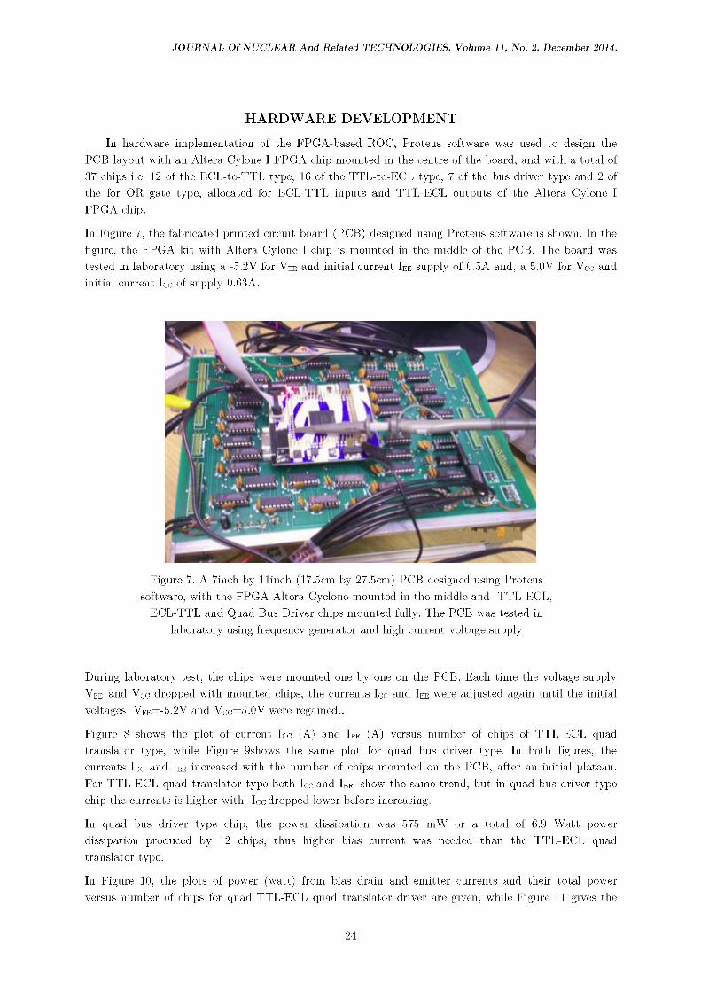
In hardware implementation of the FPGA-based ROC, Proteus software was used to design thePCB layout with an Altera Cylone IFPGA chip mounted in the centre of the board, and with a total of
37 chips i.e. 12 of the ECL-to-TTL type, 16 of the TTL-to-ECL type, 7 of the bus driver type and 2 ofthe for OR gate type, allocated for ECL-TTL inputs and TTL-ECL outputs of the Altera Cylone IFPGA chip.
In Figure 7, the fabricated printed circuit board (PCB) designed using Proteus software is shown. In thefigure, the FPGA kit with Altera Cylone Ichip is mounted in the middle of the PCB. The board was
tested in laboratory using a -5.2V for Vee and initial current Iee supply of 0.5A and, a 5.0V for Vcc andinitial current Ico of supply 0.63A.
Figure 7. A 7inch by llinch (17.5cm by 27.5cm) PCB designed using Proteussoftware, with the FPGA Altera Cyclone mounted in the middle and TTL-ECL,
ECL-TTL and Quad Bus Driver chips mounted fully. The PCB was tested in
laboratory using frequency generator and high current voltage supply
During laboratory test, the chips were mounted one by one on the PCB. Each time the voltage supply
Vee and Vcc dropped with mounted chips, the currents Icc and Iee were adjusted again until the initialvoltages Vee=-5.2V and Vce=5.0V were regained..
Figure 8 shows the plot of current Icc (A) and Iee (A) versus number of chips of TTL-ECL quadtranslator type, while Figure 9shows the same plot for quad bus driver type. In both figures, thecurrents Icc and Iee increased with the number of chips mounted on the PCB, after an initial plateau.For TTL-ECL quad translator type both Icc and Iee show the same trend, but in quad bus driver type
chip the currents is higher with Icc dropped lower before increasing.
In quad bus driver type chip, the power dissipation was 575 mW or a total of 6.9 Watt power
dissipation produced by 12 chips, thus higher bias current was needed than the TTL-ECL quadtranslator type.
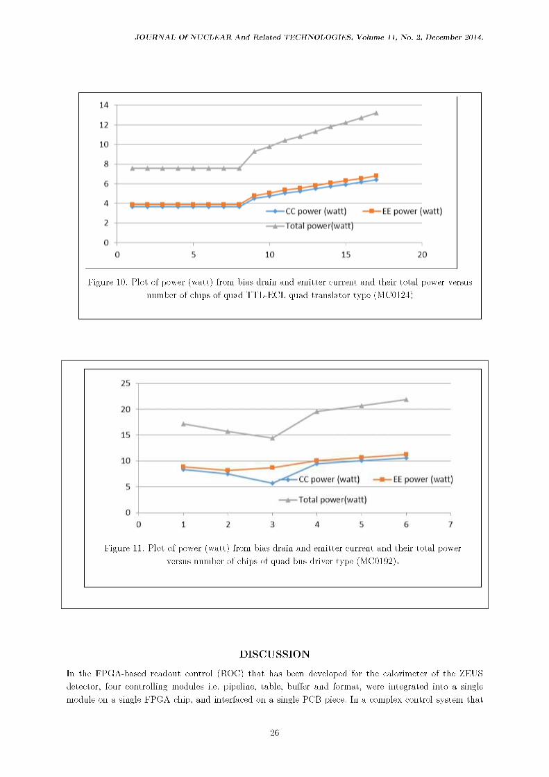
In Figure 10, the plots of power (watt) from bias drain and emitter currents and their total power
versus number of chips for quad TTL-ECL quad translator driver are given, while Figure 11 gives the
24
JOURNAL Of NUCLEAR And Related TECHNOLOGIES, Volume 11, No. 2, December 2014.
same plot for quad bus driver. In both plots, the same trend as in Figure 8 and Figure observed. Inthese figures, the linear increase in bias currents and power after a certain number of chips mounted on
the PCB indicates that improvisation of the PCB to remove excess heat dissipation is needed.
Figure 8. Plot of current Icc (A) and Iee (A) versus number of chips of
TTL-ECL quad translator type ( MC0124) showing the tendency thecurrents to increase with the number of chips
Figure 9. Plot of current Icc (A) and Iee (A) versus number of chips of quad bus driver type
(MC0192) showing the tendency the currents to increase with the number of chips
25
JOURNAL Of NUCLEAR And Related TECHNOLOGIES, Volume 11, No. 2, December 2014.
CC power (watt) EE power (watt)
Total power(watt)
Figure 10. Plot of power (watt) from bias drain and emitter current and their total power versus
number of chips of quad TTL-ECL quad translator type (MC0124)
25 n
20
15
10
Ik
ylr 1
_
_____1 -
C*--=4Lÿ— CC power (watt) — EE power (watt)
J
n* Total power(watt)
\j i i
0 121 1 1 1 1
3 4 5 6 7
Figure 11. Plot of power (watt) from bias drain and emitter current and their total power
versus number of chips of quad bus driver type (MC0192).
DISCUSSION
In the FPGA-based readout control (ROC) that has been developed for the calorimeter of the ZEUS
detector, four controlling modules i.e. pipeline, table, buffer and format, were integrated into a singlemodule on a single FPGA chip, and interfaced on a single PCB piece. In a complex control system that
26
JOURNAL Of NUCLEAR And Related TECHNOLOGIES, Volume 11, No. 2, December 2014.
uses high speed synchronization such as an accelerator, this type of control system designed on a singlechip may offer an alternative as it is compact, could be modify for diagnostic and upgrading purposes,
and could be use as disposable component in maintenance. In this paper, we demonstrated suchdiagnostic characteristic of FPGA control could be used to diagnose that the delay between pipeline andbuffer abort signals that caused unwanted data being carried into the data chain.
The implementation of the FPGA-based ROG on a single module shows that most of the energy lostthrough core static power dissipation. The interfacing of the FPGA-based ROC on a single PCB boardtogether with the translator chips would cause excess heat dissipation from the chips. Heat sinkers andfans could be of use to remove the heat dissipation excess.
The use fully FPGA-based ROC in its entirety would pose challenges. One would be to design theFPGA-controller to last as long as the interfacing electronic components of the controller, as the former
may face obsolescence.
CONCLUSION
In this paper, we have shown that integrating the four sub-modules of the ROC of a calorimeter of a
particle detector into a single module FPGA-based readout controller is feasible, as it is compact andeasier to modify in future, than the conventional system. We have also shown that the FPGA-based
ROC could be used to analyze the synchronization of accept and abort signals between the pipeline andbuffer modules in the ROC.
The design of a single module FPGA-based ROC on a single chip and mounted on 17.5cm by27.5cmPCB and surrounded by quad translators and quad bus drivers, while novel for maintenance
purposes, needs further improvement to increase its performance and reduce its power consumption andheat dissipation.
ACKNOWLEDGEMENT
The authors would like to acknowledge and extend our gratitude the ZEUS Collaboration DESY,Physics Department University of Malaya and Malaysian Nuclear Agency MOSTI in making this project
a success.
REFERENCES
A. Caldwell and S. Ritz (1992), User Interface to the CAL Electronics Readout, ZEUS-Note 92-046.
Altera Corporation, User-Customizable ARM-based SoC FPGAs for Next-Generation EmbeddedSystems, White paper, Altera Corporation, October 2011.
B. Schmidke, (2009),The CAL Readout; Columbia University/ZEUS Collaboration.
F. Mohamad Idris, Long-lived neutral hadrons in the calorimeter of the ZEUS detector, PhD thesis,University of Malaya 2011.
27
JOURNAL Of NUCLEAR And Related TECHNOLOGIES, Volume 11, No. 2, December 2014.
F. Mohamad Idris, W.A.T. Wan Abdullah, Z.A. Ibrahim, B. Kamaluddin (2009); Design and Simulation
of FPGA-Based Readout Control A High-Energy Electron-Proton Collision Calorimeter, AIPConference Proceeding Neutron and X-ray Scattering in Advancing Materials Research 2009; AIPISBN 978-0-7354-0739-8.
P. Goettlicher, Changes in the Pipeline Controller to solve the loss of FCLR, DESY/FEB May, 22nd2005.
The CMS Collaboration, Technical Proposal for the Upgrade of the CMS Detector Through 2020, CMS


![Differential inclusions of arbitrary fractional order with ...JinRong Wang1, Ahmed G. Ibrahim2 and Michal Feckan ... [25] and Gomaa [19,20]. Several results have studied fractional](https://static.documents.pub/doc/80x56/5f416d1a2ded2016b9621bef/differential-inclusions-of-arbitrary-fractional-order-with-jinrong-wang1-ahmed.jpg)


