– 1 – IEC 60969 - Self-ballasted compact fluorescent lamps for general lighting services - performance requirements Contents 1 Scope ............................................................................................................................. 2 2 Normative references ...................................................................................................... 2 3 Terms and definitions ...................................................................................................... 3 4 Marking .......................................................................................................................... 6 5 Test conditions ............................................................................................................... 7 6 Performance Criteria: assessment and compliance .......................................................... 7 Annex A (NORMATIVE) GENERAL CONDITIONS FOR MEASUREMENT OF PHOTOMETRIC AND ELECTRICAL CHARACTERISTICS AND REQUIREMENTS FOR TEST EQUIPMENT .............................................................................................. 10 Annex B (NORMATIVE) Test for starting time ...................................................................... 12 Annex C (NORMATIVE) TEST FOR RUN-UP TIME ............................................................. 14 Annex D (NORMATIVE) MEASUREMENT OF INITIAL EFFICACY AND LUMEN MAINTENANCE ........................................................................................................... 16 Annex E (NORMATIVE) TEST FOR LOW TEMPERATURE STARTING TIME ....................... 18 Annex F (NORMATIVE) TEST FOR SWITCHING WITHSTAND ............................................ 19 Annex G (NORMATIVE) TEST FOR LAMP LIFE .................................................................. 20 Annex H (NORMATIVE) TESTS FOR COMPATIBILITY WITH WALL DIMMERS AND SWITCHES .................................................................................................................. 21 Annex I (NORMATIVE) Measurement of displacement factor ............................................... 23 Annex J (NORMATIVE) Explanation of displacement factor ................................................. 25
Transcript
– 1 –
IEC 60969 - Self-ballasted compact fluorescent lamps for general lighting services - performance requirements
Contents
1 Scope ............................................................................................................................. 2 2 Normative references ...................................................................................................... 2 3 Terms and definitions ...................................................................................................... 3 4 Marking .......................................................................................................................... 6 5 Test conditions ............................................................................................................... 7 6 Performance Criteria: assessment and compliance .......................................................... 7 Annex A (NORMATIVE) GENERAL CONDITIONS FOR MEASUREMENT OF
PHOTOMETRIC AND ELECTRICAL CHARACTERISTICS AND REQUIREMENTS FOR TEST EQUIPMENT .............................................................................................. 10
Annex B (NORMATIVE) Test for starting time ...................................................................... 12 Annex C (NORMATIVE) TEST FOR RUN-UP TIME ............................................................. 14 Annex D (NORMATIVE) MEASUREMENT OF INITIAL EFFICACY AND LUMEN
MAINTENANCE ........................................................................................................... 16 Annex E (NORMATIVE) TEST FOR LOW TEMPERATURE STARTING TIME ....................... 18 Annex F (NORMATIVE) TEST FOR SWITCHING WITHSTAND ............................................ 19 Annex G (NORMATIVE) TEST FOR LAMP LIFE .................................................................. 20 Annex H (NORMATIVE) TESTS FOR COMPATIBILITY WITH WALL DIMMERS AND
SWITCHES .................................................................................................................. 21 Annex I (NORMATIVE) Measurement of displacement factor ............................................... 23 Annex J (NORMATIVE) Explanation of displacement factor ................................................. 25
– 2 –
Self-ballasted compact fluorescent lamps for general lighting services - performance requirements
1 Scope
This international standard specifies performance requirements together with test methods and conditions required to show compliance of self-ballasted compact fluorescent lamps intended for general lighting services.
This Standard applies to self-ballasted compact fluorescent lamps of voltages > 50V and all power ratings with lamp caps complying with IEC 60061-1.
NOTE: Some features of this standard may be applicable to self-ballasted compact fluorescent lamps of voltages ≤ 50V and to other types of self-ballasted gas discharge lamps.
The requirements of this standard relate only to type testing.
The performance requirements specified in this standard are additional to the safety requirements specified in IEC 60968.
1.1 Statement Self-ballasted compact fluorescent lamps, which comply with this standard, shall start and operate satisfactorily at normal conditions (voltages between 92% and 106% of rated supply voltage, ambient air temperature of between -10 °C and 40 °C and in a luminaire complying with IEC 60598-1).
If a supplier claims suitability for operation at extended conditions (voltages or temperatures outside of normal conditions, including high humidity) then:
a) Lamps shall be tested under claimed extended conditions; and
b) Lamps shall start and operate satisfactorily under claimed extended conditions; and
c) Lamps shall meet all performance claims for operation under claimed extended conditions, which may differ from the performance claims under the general conditions for measurement specified in A.1.
2 Normative references
The following referenced documents are indispensable for the application of this document. For dated references, only the edition cited applies. For undated references, the latest edition of the referenced document (including any amendments) applies.
IEC 60050(845), International Electrotechnical Vocabulary—Lighting IEC 60061-1 Lamp caps and holders together with gauges for the control of interchangeability and safety - Part 1: Lamp caps IEC 60081, Double-capped fluorescent lamps—Performance specification Referenced for colour IEC 60630 Maximum Lamp Outlines for incandescent lamps. IEC 60968, Self-ballasted lamps for general lighting services - Safety requirements IEC 60598-1, Luminaires – Part 1: General requirements and tests. IEC 61000-3-2, Electromagnetic compatibility (EMC) - Part 3-2: Limits - Limits for harmonic current emissions (equipment input current <= 16 A per phase) IEC/TR 61341, Method of measurement of centre beam intensity and beam angle(s) of reflector lamps
– 3 –
IEC 62554 Measurement of mercury level in fluorescent lamps. (under preparation, at RVC stage) CIE 13.3, Method of Measuring and Specifying Colour Rendering Properties of Light Source CIE 15, Colorimetry CIE 63, The spectroradiometric measurement of light sources CIE 69: Methods of Characterizing Illuminance Meters and Luminance Meters: Performance, Characteristics and Specifications CIE 84, Measurement of luminous flux CIE 121, The photometry and goniophotometry of luminaires CIE 179, Methods for characterising tristimulus colorimeters for measuring the colour of light
3 Terms and definitions
For terms and definitions refer to the following sub-clauses.
3.1 Self-ballasted lamp
A unit which cannot be dismantled without being permanently damaged, provided with a lamp cap and incorporating a light source and any additional elements necessary for starting and stable operation of the light source. A self-ballasted lamp is referred to as a lamp in this standard.
3.2 New lamp
A lamp which has not been energised since manufacture.
3.3 Rated value
Quantity value, assigned by the supplier, for a lamp characteristic under specified operating conditions (for example rated luminous flux).
3.4 Test voltage
The input voltage at which tests are carried out.
3.5 Initial values
Photometric and electrical characteristics measured at the end of a 100 hour ageing period.
3.6 Lamp failure
The moment at which the lamp fails to light up, fails to remain alight or delivers low light output (in case of doubt, low light output refers to less than approximately 50% of rated light output).
– 4 –
3.7 Lamp life (of an individual lamp)
The number of operating hours to lamp failure.
3.8 Median of lamp life
The number of operating hours elapsed at which point 50% of a representative group of lamps have failed, when operated under specified test conditions.
3.9 Colour The colour characteristics of a lamp are defined by 3 items:
a) Chromaticity coordinates [IEV 845-03-33]
b) Correlated colour temperature (CCT) [IEV 845-03-50]
c) Colour rendering index (CRI) [IEV 845-02-61]
3.9.1 Colour code
3-digit code expressing the rated colour rendering index and the rated correlated colour temperature as described in TRxxxxx.
3.10 Starting time
The time required for a lamp to develop an electrically stable arc discharge, the time being measured from the moment the lamp circuit is energised.
3.11 Run-up time
The time required for a lamp to reach a specified percentage of its initial (stable) luminous flux, the time being measured from the moment the lamp circuit is energised.
3.12 Displacement Factor
The cosine of the phase-angle between the fundamental harmonic current and the mains voltage. The displacement factor shall be measured in accordance with Annex I.
3.13 Distortion factor
A factor indicating the level of harmonic current distortion, described as follows:
The total harmonic distortion (THDi) is calculated according to IEC 61000-3-2. See Annex J for further explanation of distortion factor.
3.14 Lumen maintenance
– 5 –
The luminous flux at a given time in the life of a lamp, divided by the initial luminous flux of the lamp, and expressed as a percentage of the initial luminous flux.
3.15 Lamp type
Lamps that, independent of the type of cap, have identical photometric and electrical ratings.
3.16 Lamp stabilisation time
Time required for a lamp to reach stable conditions for measurement.
3.17 Type test
A test or series of tests made on a type test sample for the purpose of checking compliance of the design of a given product with the requirements of the relevant standard.
3.18 Type test sample
Sample consisting of one or more similar units submitted by the supplier for the purpose of the type test.
3.19 Efficacy
Quotient of the lamp luminous flux by the lamp power consumption.
3.20 Beam angle
The beam angle is as defined in IEC TR 61341.
3.21 Ageing
Preconditioning of lamps by operating them at controlled conditions for a specified period.
3.22 Supplier
Manufacturer, responsible vendor or importer.
3.23 Non-dimmable lamp
Lamp that is marked non-dimmable.
3.24 Dimmable lamp
Lamp that is marked dimmable.
– 6 –
4 Marking
4.1 General requirements for marking For this performance standard the following data shall be provided (in addition to the mandatory data required by IEC 60968) by the supplier and located as specified in Table 1. The rated values refer to performance claims under the general conditions for measurement as specified in A.1.
Table 1 – Locations where marking of rated values is required (x = required, - = not required but optional)
Parameter (Rated) Product Product Packaging
Product datasheets or leaflets
a) Initial luminous flux of the lamp (lumens)
(luminous flux for reflector lamps is under consideration) - x x
b) Beam angle (degrees) and centre beam intensity (candela) for reflector lamps - x x
c) Initial efficacy (lumens/Watt) - - x
d) Correlated colour temperature (kelvin)
(alternatively, colour code is permissible on product) x x x
e) Colour rendering index - x x
f) Chromaticity coordinates - - x
g) Median lamp life (hours) - x x
h) Lumen maintenance (%)
Including operating hours at which lumen maintenance value(s) are claimed
- - x
i) Switching withstand (no. of cycles) - - x
j) Special operating requirements
e.g. dimming, orientation (base up/down), restricted operating temperature range
- x x
k) Starting time (seconds) - - x
l) Low temperature starting time (seconds)
(and temperature if lower than -10°C) - - x
m) Run-up time (seconds) - x x
n) Displacement factor - - x
o) Distortion factor - - x
– 7 –
Parameter (Rated) Product Product Packaging
Product datasheets or leaflets
p) Dimensions (mm) - - x
q) Performance claims for extended conditions - - x
r) Location of additional information
(how to find product datasheets or leaflets) - x -
If equivalence with an incandescent lamp is claimed, the claimed equivalent incandescent lamp power (rounded to 1 W) shall be that corresponding to the table below. The intermediate values of both the luminous flux and the claimed incandescent lamp power (rounded to 1W) shall be calculated by linear interpolation between two adjacent values.
Table 2 – Equivalency with incandescent lamps
Claimed equivalent incandescent lamp
power (W)
(for 220-240V regions) Minimum rated
luminous flux of CFL (lm)
(for 110-120V regions) Minimum rated
luminous flux of CFL (lm)
15 125 155
25 229 279
40 432 512
60 741 861
75 970 1120
100 1398 1598
150 2253 2553
200 3172 3572
Drafting note: 220-240V values have been taken from EU regulations. 110-120V values are based on these lamps having a +2.0 lm/W efficacy advantage over 220-240V lamps. This advantage has been calculated from lamp data sheets in IEC 60064.
5 Test conditions
Conditions for testing are given in Annex A.
For lamps with special features e.g. dimming and daylight sensing, the supplier shall provide advice on how to disable these features in order to test the lamp.
Where applicable, sample sizes and compliance conditions for various requirements are given in Table 3.
6 Performance Criteria: assessment and compliance
6.1 General A lamp, on which compliance with this standard is claimed, shall comply with the requirements of IEC 60968.
A lamp shall be designed so that its performance is reliable in normal and accepted use. In general this can be achieved by satisfying the requirements of the following subclause.
The requirements and information given apply to 95 % of production.
NOTE The requirements and tolerances permitted by this standard correspond to the testing of a type test sample, submitted by the manufacturer for that purpose. In principle this type test sample should consist of units having
– 8 –
characteristics typical of the manufacturer’s production and being as close to the production centre point values as possible.
It may be expected with the tolerances given in the standard that products manufactured in accordance with the type test sample will comply with the standard for the majority of production. Due to the production spread however, it is inevitable that there will sometimes be products outside the specified tolerances. For guidance on sampling plans and procedures for inspection by attributes, refer to IEC 60410.
6.2 Performance requirements Lamps shall be assessed against all the parameters listed in Table 3 (column B). Minimum sample sizes for each test are specified in Table 3 (column C). Compliance conditions for all parameters are listed in Table 3 (column D). Test conditions are listed in Table 3 (column E).
Note: There are local and regional regulations for many of these and other parameters.
Table 3 - Sample sizes, compliance criteria and test conditions
A B C D E
Row Parameter for Test
Minimum type test sample size Compliance Test condition for
compliance
Initial power 10
Mean measured value shall be between 90% and 110% of rated value, and all samples shall measure between 85% and 115% of rated value.
Annex A
Power quality - displacement factor
10 All samples shall measure within limits listed in Annex J, and all samples shall measure within rated limits.
Annex I Annex J
Power quality – distortion 10
All samples shall be within limits for harmonic distortion as per IEC 61000-3-2, and all samples shall measure within rated limits.
IEC 61000-3-2
Initial luminous flux
10 (50% of samples in base up position)
Mean measured value shall be ≥ 90% of rated value, and all samples shall measure ≥ 85% of rated value.
Annex D
Beam angle (reflector lamps) 1 Mean measured beam angle shall be
within ±25 % of rated value. IEC/TR 61341
Centre beam intensity (reflector lamps)
1 Mean measured centre beam intensity shall be ≥ 75% of rated value. IEC/TR 61341
Chromaticity coordinates* 10
Chromaticity coordinates of all samples shall measure within 5 SDCM of rated value.
CIE ??
Colour Rendering Index (CRI) 10 CRI of all samples shall measure ≥ rated
CRI value minus 3. CIE 13.3
Starting time 6
Mean measured value shall be ≤ 1.5 seconds, and all samples shall start within 2.0 seconds. Mean measured value shall be ≤110% of rated value.
Annex B
Low temperature starting
6
At the rated minimum starting temperature, all lamps shall start within the time specified by the supplier.
Annex E
Run-up time 6
The mean measured time, to reach the specified percentage of initial luminous flux, shall be ≤110% of the rated time. All samples shall reach the specified percentage of initial luminous flux within 125% of the rated time.
Annex C
– 9 –
A B C D E
Row Parameter for Test
Minimum type test sample size Compliance Test condition for
compliance
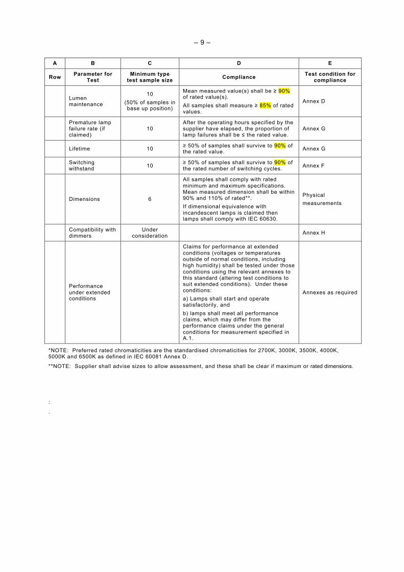
Lumen maintenance
10 (50% of samples in base up position)
Mean measured value(s) shall be ≥ 90% of rated value(s). All samples shall measure ≥ 85% of rated values.
Annex D
Premature lamp failure rate (if claimed)
10 After the operating hours specified by the supplier have elapsed, the proportion of lamp failures shall be ≤ the rated value.
Annex G
Lifetime 10 ≥ 50% of samples shall survive to 90% of the rated value. Annex G
Switching withstand 10 ≥ 50% of samples shall survive to 90% of
the rated number of switching cycles. Annex F
Dimensions 6
All samples shall comply with rated minimum and maximum specifications. Mean measured dimension shall be within 90% and 110% of rated**. If dimensional equivalence with incandescent lamps is claimed then lamps shall comply with IEC 60630.
Physical measurements
Compatibility with dimmers
Under consideration Annex H
Performance under extended conditions
Claims for performance at extended conditions (voltages or temperatures outside of normal conditions, including high humidity) shall be tested under those conditions using the relevant annexes to this standard (altering test conditions to suit extended conditions). Under these conditions: a) Lamps shall start and operate satisfactorily, and b) lamps shall meet all performance claims, which may differ from the performance claims under the general conditions for measurement specified in A.1.
Annexes as required
*NOTE: Preferred rated chromaticities are the standardised chromaticities for 2700K, 3000K, 3500K, 4000K, 5000K and 6500K as defined in IEC 60081 Annex D.
**NOTE: Supplier shall advise sizes to allow assessment, and these shall be clear if maximum or rated dimensions.
:
.
– 10 –
Annex A (NORMATIVE)
GENERAL CONDITIONS FOR MEASUREMENT OF PHOTOMETRIC AND ELECTRICAL CHARACTERISTICS AND REQUIREMENTS FOR TEST
EQUIPMENT
A.1 Method of measuring lamp characteristics
Sample sizes and compliance conditions for tests are given in Table 3.
The visual appearance of all samples shall be checked before testing, and if required all samples shall be cleaned before photometric testing.
Unless specified elsewhere all tests shall:
(a) Be made in a draught-free atmosphere at an ambient temperature of (25 ±1) °C and a relative humidity of 65% maximum. If lamp operation in a more severe atmosphere is claimed by the supplier, operation at this atmosphere shall also be tested. Air movement shall be in accordance with CIE 121. For lamp ageing, the lamp life test and the switch withstand test, the ambient temperature of the room shall be in the range of 15°C to 40°C, and some draught is allowed but vibration and shock should be minimised.
(b) Be carried out at rated voltage and frequency if a single value is declared. If the rated voltage is a range, the lamp shall be aged and tested at the mean voltage of that range. For dual-voltage lamps, for example those intended for operation at 110-130 V and 220-240 V, ageing and testing shall be conducted at mean of each voltage range.
(c) Have a test voltage tolerance during ageing and luminous flux maintenance testing within 2%. During lamp stabilisation the voltage shall be within ± 0,5%. At the moment of measurement the tolerance shall be within ± 0,2% for voltage and ± 0,2 % for frequency. The total harmonic content of the supply voltage shall not exceed 3%. The harmonic content is defined as the R.M.S. summation of the individual harmonic components using the fundamental as 100%.
Note. Refer IEC 61000-3-2, Annex A, subclause A.2
(d) Unless otherwise specified for a specific purpose by the supplier, lamps shall be operated in free air in a vertical base-up position for all tests including lumen maintenance tests. If a supplier has declared the lamp is suitable for use in a specific orientation only, then the lamp shall be mounted in the declared orientation during all tests.
A.2 Lamp stabilisation
Measurements shall be made after the lamp stabilisation time. NOTE. During shipping and normal handling of the lamps, e.g. rotating of the lamp, any excess amount of mercury may be distributed in small droplets within the discharge tube. Proper conditioning is reached when all the excess mercury has been collected at the coldest spot in the tube. Experience has shown that initially this process of lamp conditioning may take up to 16 h. When a lamp, once having passed this conditioning period it is ready for measurement
For conditioning and warming up the lamp may be operated in a location, distant to the test location. When moving to the test location, provided that the lamp has been kept in the same orientation, not subjected to vibration or shock and no warm glass parts are touched (i.e. creating a parasitic cold spot), a stabilisation period of 15 – 60 minutes is necessary in the test location. To avoid cooling down of warm glass parts during moving the lamp to test location thermally insulating gloves or similar technique shall be used. The interruption of the supply should be as short as possible. If deviating from the values in the table A.1, the relevant specification of the supplier should be observed.
Measurements shall not start before stabilisation is reached. During the final 15 minutes of the minimal stabilisation time (table A1), measurement of light output must be taken once per minute. Stabilisation is achieved if the difference of maximum and minimum readings of light output is less than 1%. If not, the observation period is prolonged until 15 successive
– 11 –
readings fulfil the requirement. If this cannot be achieved within 30 minutes, the real fluctuation shall be stated.
Table A.1 Conditioning, off time and stabilisation time
Minimum conditioning time (hours)* 16 Maximum off time (transport to test location) (minutes) 5 Stabilisation time (minutes) 15-60
*NOTE: this can be part of ageing
A.3 Lamp ageing and life test
Unless specified elsewhere, lamp ageing shall take place in the ageing facility for the specified number of hours of operation.
For life testing, lamps shall be repeatedly cycled for 2 h 45 min ON followed by 15 min OFF.
Ageing hours and life hours shall only be deemed to have occurred during the periods when the lamp is ON.
A.4 Electrical measurement
Electrical measurements (power, current and power quality) shall be conducted on lamps aged for 100 h.
Instruments shall be of the true r.m.s. type, essentially free from waveform errors and of a precision appropriate to the requirements
A.5 Luminous flux measurement
Photometric characteristics shall be measured in accordance with the relevant recommendations of the CIE (Commission Internationale de l'Eclairage).
A.6 Time and cycles measurement
Appropriate measurement accuracies for time and cycle measurements are
Starting time: ± 0,1 s Run-up time: ±3 s Lamp life: ± 100 h Lumen maintenance: ± 100 h Ageing: ± 5 h Switching cycle time: ±3 s Switching withstand cycles: ± 200 cycles
– 12 –
Annex B (NORMATIVE)
Test for starting time
B.1 General
The starting time test shall be conducted on lamps aged for 100 h.
Prior to the test the lamps shall be stored in planned test position for at least 22 h at 20°C to 27°C ambient temperature, and additional storing shall be at least 2 h at 25°C ± 1°C ambient temperature.
Sample sizes and compliance conditions for this test are given in Table 3.
For the starting time test an Integrating sphere as per Clause A.5.2 is the preferred method as lamps do not illuminate evenly during starting.
B.2 Test conditions
B.2.1 Test voltage B.2.1.1 Non-dimmable lamps The test voltage for the starting test shall be equal to 92% of the lowest given rated voltage using a supply as defined in A1 (c).
B.2.1.2 Dimmable lamps The test voltage for the starting test shall be equal to 92% of the lowest given rated voltage using a supply as defined in A1 (c).
Additional tests for dimmable lamps are under consideration.
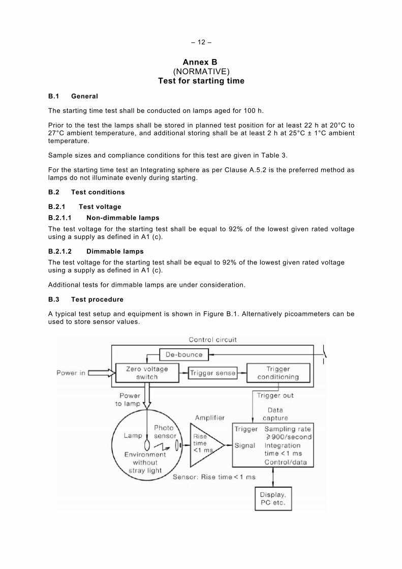
B.3 Test procedure
A typical test setup and equipment is shown in Figure B.1. Alternatively picoammeters can be used to store sensor values.
– 13 –
Figure B.1 – Typical setup for starting time test
(1) The test equipment and the measurement device(s) shall be in a state such that the lamp test can immediately be started.
(2) Switch on power to the lamp and triggering equipment as required.
(3) The test shall run until the lamp starts fully and remains alight. If after a reasonable period the lamp does not start, cease the test.
(4) Record luminous flux over time together with ambient temperature and relative humidity.
B.4 Calculations
The starting time is determined as the period from the start of the test to when the lamp has fully completed the starting sequence (lamp fully started and remains alight) as observed by the front edge of the first plateau in the envelope of the light output signal.
– 14 –
Annex C (NORMATIVE)
TEST FOR RUN-UP TIME
C.1 General
The run-up time test shall be conducted on lamps aged for 100 h.
Prior to the test the lamps shall be stored in planned test position for at least 22 h at 20°C to 27°C ambient temperature, and additional storing shall be at least 2 h at 25°C ± 1°C ambient temperature.
Sample sizes and compliance conditions for this test are given in Table 3.
For the run-up time test an Integrating sphere as per Clause A.5.2 is the preferred method.
C.2 Test conditions
The test conditions and equipment shall be as specified in Annex A
A typical test setup and equipment is shown in Figure C.1.
Figure C.1 – Typical Set-up for run-up time test
C.3 Test procedure
An example of test equipment setup is given in Figure C.1.
(1) The test equipment and the measurement device(s) shall be in a state that the lamp test can immediately be started.
(2) Switch on power to the lamp and triggering equipment as required.
(3) The test shall run until the lamp light output is stable as defined in A.2.
(4) Record luminous flux over time together with ambient temperature and relative humidity.
– 15 –
C.4 Calculations
From the test data, determine the time taken from the start of the test, to when the lamp achieves the required percentage of its initial luminous flux.
– 16 –
Annex D (NORMATIVE)
MEASUREMENT OF INITIAL EFFICACY AND LUMEN MAINTENANCE
D.1 General
The measurement of initial luminous flux shall be conducted on lamps aged for 100 h.
Sample sizes and compliance conditions for this test are given in Table 3.
D.2 Test conditions
The test conditions and equipment shall be as specified in Annex A
The circuit in Figure D.1 should be used:
Figure D.1 – Measurement of luminous flux
D.3 Test procedure
D.3.1 General The lamp shall be left to reach a stable condition as defined in A.2.
D.4 Initial efficacy test
D.4.1 Test procedure The test shall be conducted on lamps aged for 100 h
Sample sizes and compliance conditions for this test are given in Table 3.
During the procedure for measurement of initial luminous flux, simultaneously measure lamp power and record the data.
Initial luminous flux and initial lamp wattage shall be measured from same test lamp.
D.4.2 Calculations Following the calculation of luminous flux, initial efficacy is calculated as follows:
Luminous flux / lamp power. units: lm/W
D.5 Lumen maintenance test
The sample of lamps that underwent initial efficacy tests, or new lamps, shall be aged under the same conditions as described in Annex A.3 for the specified number of hours.
The luminous flux shall be measured after 100 h and after other elapsed periods as required to prove compliance with rated values.
– 17 –
All luminous flux measurements, calculated lumen maintenance and calculated efficacy values shall be recorded. Sample size and compliance conditions for this test are given in Table 3. If 3 or more lamps fail, cease the test.
– 18 –
Annex E (NORMATIVE)
TEST FOR LOW TEMPERATURE STARTING TIME
E.1 General
The low-temperature starting time test shall be conducted on lamps that have been aged for 100 hours.
Sample sizes and compliance conditions for this test are given in Table 3.
E.2 Test conditions
The test voltage for the starting test shall be equal to 92% of the lowest given rated voltage using a supply as defined in A1 (c)
The test temperature is the supplier’s rated minimum starting temperature or, if a rated minimum starting temperature is not supplied, then the test temperature shall be –10°C. Prior to the test, the lamps shall be stored in the planned test position for at least 20 h at or near the test temperature, and additional storing shall be at least 4 hours at the test temperature ± 1 K. The lamps shall be stored in a dark room or internally black box.
E.3 Test procedure
(a) Test lamps in a dark room or internally black box.
(b) The lamp shall be switched on and a timing device used to record the time when the lamp starts fully and remains alight.
(c) The ability of the lamp to start at the specified temperature shall be confirmed by visual inspection or other methods.
(d) Cease the test if lamp fails to start within the rated time.
– 19 –
Annex F (NORMATIVE)
TEST FOR SWITCHING WITHSTAND
Sample sizes and number of cycles compliance conditions for this test are given in Table 3.
Lamps shall be aged for 2 hours minimum for this test.
NOTE Lamps aged to 100 hours can be used if there are multiple aged lamps available.
The test conditions and equipment shall be as specified in Annex A for lamp ageing and life test. The switching cycle used for the Switching Withstand test shall be 3 min off, 1 min on.
The number of switching cycles until lamp failure occurs shall be recorded for each lamp.
The test shall be continued until the rated number of switching cycles is reached or more than half of the sample lamps population cease to operate.
– 20 –
Annex G (NORMATIVE)
TEST FOR LAMP LIFE
Sample sizes and compliance conditions for this test are given in Table 3.
The sample of lamps shall be new or aged for a maximum of 100 h.
Lamps shall be operated with switching cycle as shown in Annex A for lamp ageing and life test.
The hours of operation until lamp failure occurs shall be recorded for each lamp. The lamp is deemed to have failed if it fails to light up, fails to remain alight or delivers less than approximately 50% of its rated light output. The failure to light up is confirmed by visual inspection.
Recorded hours of operation shall only include the periods of the cycle when the lamp was on. Hours of operation shall include any initial ageing period.
The test shall be continued until the rated lifetime is reached or more than half of the sample population fail – whichever occurs first.
– 21 –
Annex H (NORMATIVE)
TESTS FOR COMPATIBILITY WITH WALL DIMMERS AND SWITCHES
H.1 Inrush current of dimmable and non-dimmable lamps
H.1.1 General Due to a too high inrush current, the contacts of (electronic) switches may damage.
H.1.2 Inrush current limitation The inrush current of an individual lamp shall be limited according to the table H.1
Table H.1 Inrush current limitations and test conditions
Lamp Power, P (W)
Vtest (V rms)
Ip (A)
I2t (A2 s)
Zmains
P<15 120 60 0,50 0,450 Ω + 100 µH
P<15 230 20 0,08 0,2 Ω + 400 µH
15<P<=25 120 60 0,50 0,450 Ω + 100 µH
15<P<=25 230 35 0,15 0,2 Ω + 400 µH
H.2 Specific requirements for dimmable lamps
Drafting note: this section of the proposal is under development and is to be confirmed together with 23B
Dimming range Add test requirement to compare vs label
Smooth changes Add requirement for monotonic light level change
Connected load GLS VA rating corresponds with 1/5 CFLi load
Turning off Add leakage minimum pass-through current (timing and value) requirement and test
– 22 –
Lamp reliability Tests with phase-cut dimmer circuits (dimmable CFL and non-dimmable CFL)
Dimmer reliability Inrush current criteria
Audible noise Add audible noise limits
H.3 Dimmer compatibility marking
H.3.1 Dimmable self-ballasted lamp
H.3.2 Non dimmable self-ballasted lamp
H.3.3 Dimmable self-ballasted lamp with restrictions
Adjacent text on product packaging and product datasheets or leaflets shall give details of restrictions.
– 23 –
Annex I (NORMATIVE)
Measurement of displacement factor
I.1 Introduction
The phase-angle (φ1) of the displacement factor (cos φ1) of Clause XX shall be measured according to the definition of Annex I.2 and with the measurement requirements of Annex I.3.
I.2 Phase-angle definition
The phase-angle (φ1) between the fundamental harmonic current (I1) and the mains-voltage (Umains) is determined as described in Figures I.1 and I.2.
Figure I.2 - Definition of the 1st harmonic current phase-angle (φ1)
(I1 lags Umains), φ1 < 0)
I.3 Measurements requirements
I.3.1 Measurement circuit and supply source The measurement circuit and the supply source are defined in Annex A of IEC 61000-3-2
I.3.2 Requirements for measurement equipment The requirements for measurement equipment are defined in IEC 61000-4-7
I.3.3 Test conditions The test conditions for the measurements of the displacement / phase-angle associated with some types of equipment are given in the following clauses: See Annex C, C.5 of IEC 61000-3-2.
– 25 –
Annex J (NORMATIVE)
Explanation of displacement factor
J.1 Introduction
The metric power factor (λ) is a composite metric and consists of the primary metrics displacement factor (κdisplacement) and distortion factor (κdistortion).
The relation between the composite metric λ and its primary metrics κdisplacement and κdistortion is as follows:
Angle φ1 is the phase angle between the fundamental of the supply voltage and the fundamental of the mains current. The Total Harmonic Distortion (THDi) is quantified by the harmonics of the mains current, according to IEC 61000-3-2. The relation between the individual harmonics of the mains current and the THDi is in below equation:
Where In is the amplitude of the nth harmonic of the mains current.
– 26 –
J.2 Limits for displacement factor
No negative effects on the power grid are to be expected from self-ballasted compact fluorescent lamps when complying with the recommended limits in Table J.1.
Table J.1 Recommended values for displacement factor
Bibliography IEC 61000-3-2, Electromagnetic compatibility (EMC) - Part 3-2: Limits - Limits for harmonic current emissions (equipment input current <= 16 A per phase) IEC 62554 Measurement of mercury level in fluorescent lamps. (under preparation, At IEC RVC stage refer 34A/1411/RVC) CIE 1931, CXYZ colour space IEC 61547, Equipment for general lighting purposes - EMC immunity requirements IEC CISPR 15, Limits and methods of measurement of radio disturbance characteristics of electrical lighting and similar equipment ** END OF DRAFT **