4.2.2 Risk components for a structure due to flashes to the structure................ 21
4.2.3 Risk component for a structure due to flashes near the structure....... .... ... 21
4.2.4 Risk components for a structure due to flashes to a line connected tothe structure ....................................................................................... 21
4.2.5 Risk component for a structure due to flashes near a line connectedto the structure ................................................................................... 21
6.2 Assessment of risk components due to flashes to the structure (S1) .. .. .. .. .. .. .. .. .. .. 29
6.3
Assessment of the risk component due to flashes near the structure (S2) .. .. .. .. .. .. 29
6.4 Assessment of risk components due to flashes to a l ine connected to thestructure (S3) ................................................................................................ 29
6.5 Assessment of risk component due to flashes near a l ine connected to thestructure (S4) ................................................................................................ 30
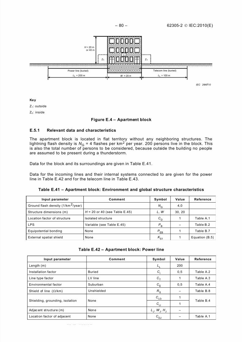
Figure 1 – Procedure for deciding the need of protection and for selecting protectionmeasures .................................................................................................................... 26
Figure 2 – Procedure for evaluating the cost-effectiveness of protection measures ..... .... .... 27
Figure A.1 – Collection area AD of an isolated structure ...................... ............. ............. ... 35
Table 1 – Sources of damage, types of damage and types of loss according to thepoint of strike ............ ............. ............. ............. ............. ............. ............. ............. ........ 20
Table 2 – Risk components to be considered for each type of loss in a structure .... .... .... .... . 22
Table 4 – Typical values of tolerable risk R T .................................................................... 24
Table 5 – Parameters relevant to the assessment of risk components .... .... .... .... ..... .... .... ... 30
Table 6 – Risk components for different types of damage and source of damage ..... .... .... ... 31
Table A.1 – Structure location factor C D.......................................................................... 39
Table A.2 – Line installation factor C I ............................................................................. 40
Table A.3 – Line type factor C T ...................................................................................... 40
Table A.4 – Line environmental factor C E ........................................................................ 40
Table B.1 – Values of probability P TA that a flash to a structure will cause shock toliving beings due to dangerous touch and step voltages ............... ............. ............. .......... 42
Table B.2 – Values of probability P B
depending on the protection measures to reducephysical damage .......................................................................................................... 43
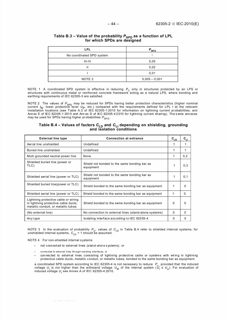
Table B.3 – Value of the probability P SPD as a function of LPL for which SPDs aredesigned ..................................................................................................................... 44
Table B.4 – Values of factors C LD and C LI depending on shielding, grounding andisolation conditions ....................................................................................................... 44
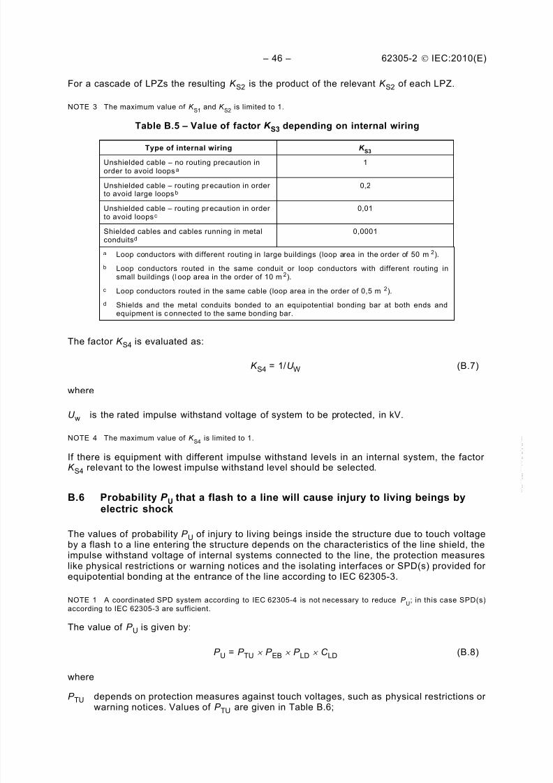
Table B.5 – Value of factor K S3 depending on internal wiring............................................ 46
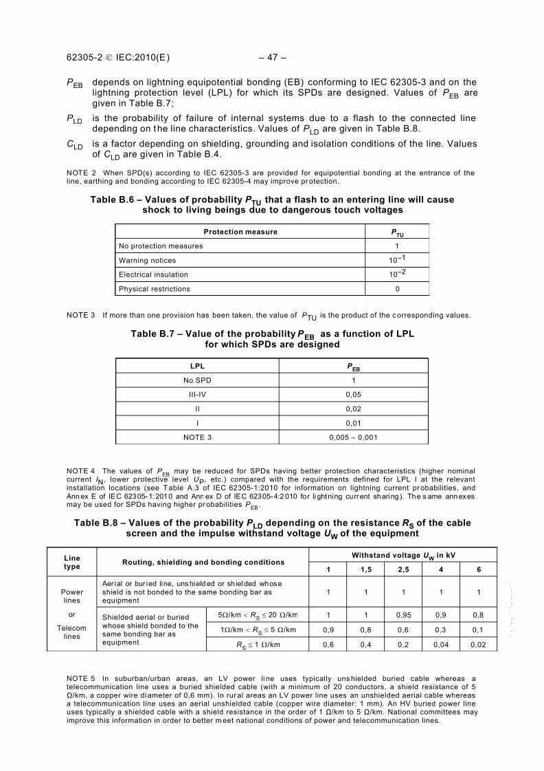
Table B.6 – Values of probability P TU that a flash to an entering line will cause shockto living beings due to dangerous touch voltages ............ ............. ............. ............. .......... 47
Table B.7 – Value of the probability P EB as a function of LPL for which SPDs aredesigned ..................................................................................................................... 47
Table B.8 – Values of t he probability P LD depending on the resistance R S of the cablescreen and the impulse withstand voltage U W of the equipment ................. ............. .......... 47
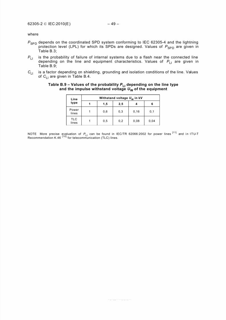
Table B.9 – Values of t he probability P LI depending on the line type and the impulsewithstand voltage U W of the equipment ........... ............. ............. ............. ............. ............ 49
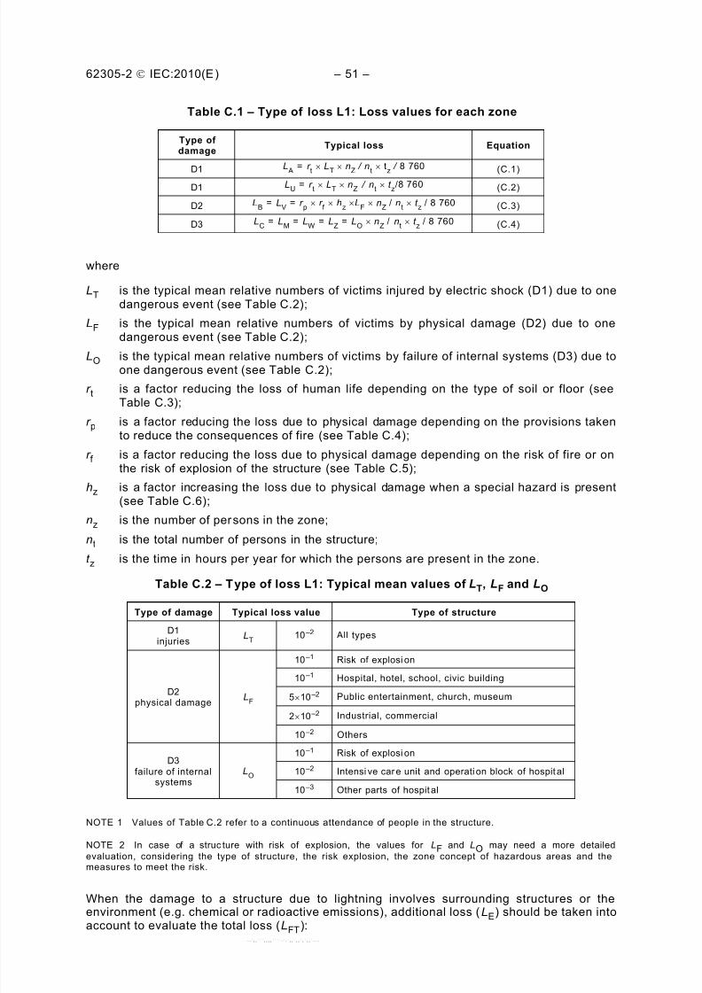
Table C.1 – Type of loss L1: Loss values for each zone ...................... ............. ............. ... 51
Table C.2 – Type of loss L1: Typical mean values of LT, LF and LO ................................... 51
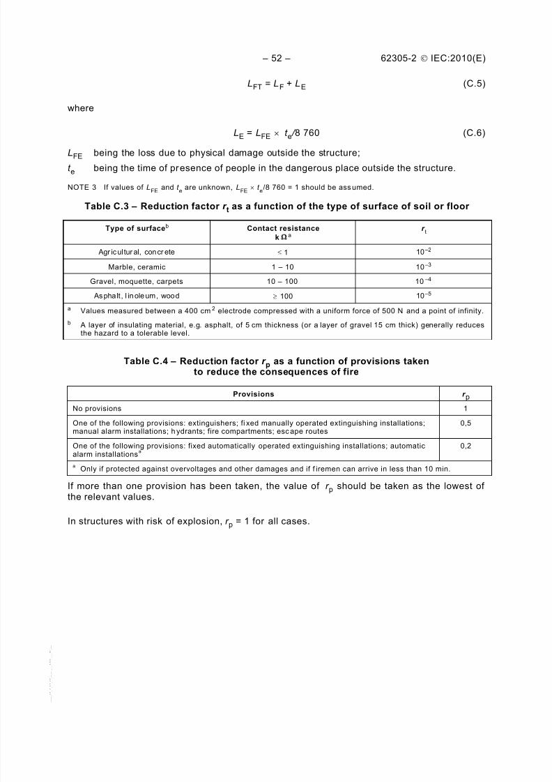
Table C.3 – Reduction factor r t as a function of the type of surface of soil or floor .... .... .... ... 52
Table C.4 – Reduction factor r
p
as a function of provisions taken to reduce the
consequences of fire..................................................................................................... 52
Table C.5 – Reduction factor r f as a function of risk of fire or explosion of structure ..... .... ... 53
Table C.6 – Factor hz increasing the relative amount of loss in presence of a specialhazard ......................................................................................................................... 53
Table C.7 – Type of loss L2: Loss values for each zone ...................... ............. ............. ... 54
Table C.8 – Type of loss L2: Typical mean values of LF and LO ........... ............. ............. .... 54
Table C.9 – Type of loss L3: Loss values for each zone ........................ ............. ............. . 54
Table C.10 – Type of loss L3: Typical mean value of LF ................................................... 55
Table C.11 – Type of loss L4: Loss values for each zone ............ ............. ............. ............ 55
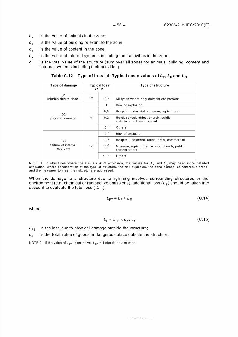
Table C.12 – Type of loss L4: Typical mean values of LT, LF and LO ............. ............. ........ 56
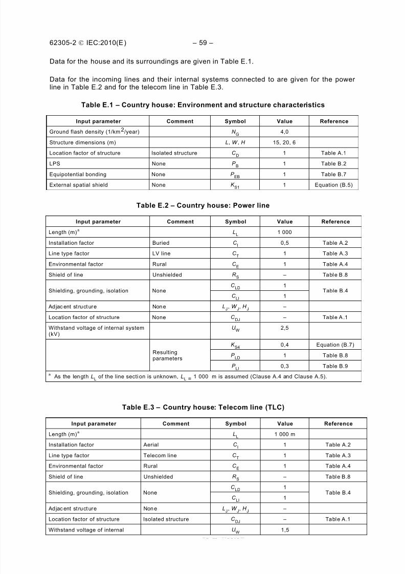
Table E.1 – Country house: Environment and structure characteristics............................... 59
Table E.2 – Country house: Power line ............. ............. ............. ............. ............. .......... 59
Table E.3 – Country house: Telecom line (TLC) ............ ............. ............. ............. ............ 59
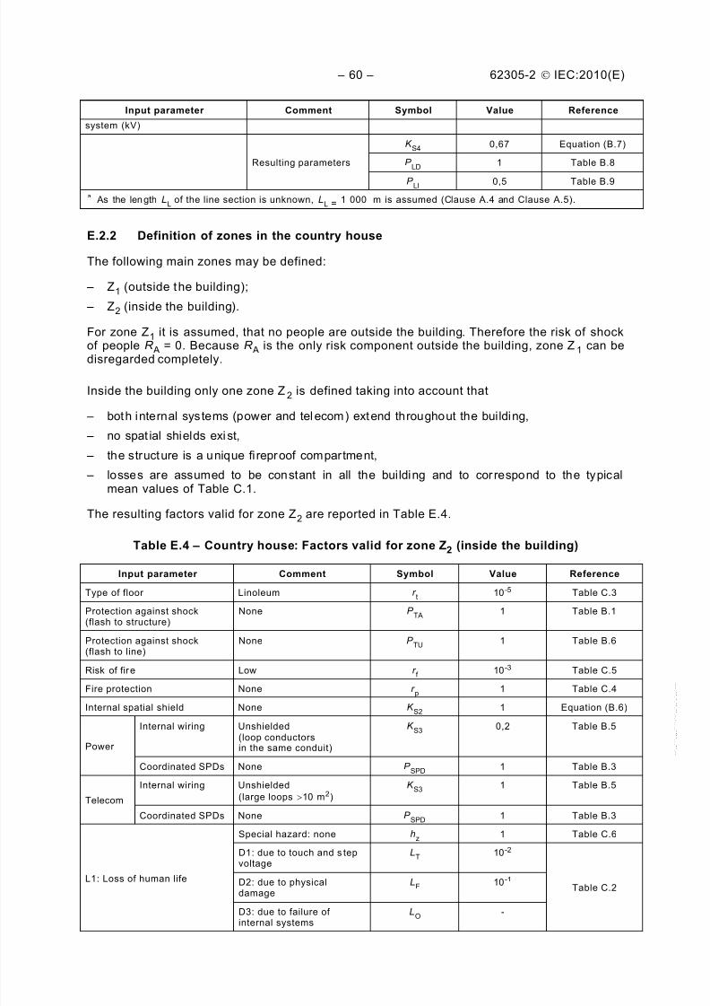
Table E.4 – Country house: Factors valid for zone Z2 (inside the building).................... ...... 60
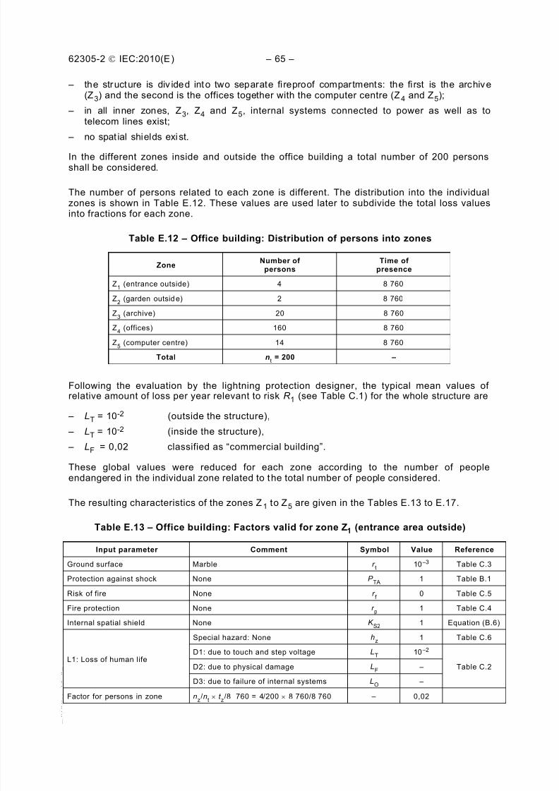
Table E.5 – Country house: Collection areas of structure and lines ............. ............. .......... 61
Table E.6 – Country house: Expected annual number of dangerous events ...... .... .... ..... .... . 61
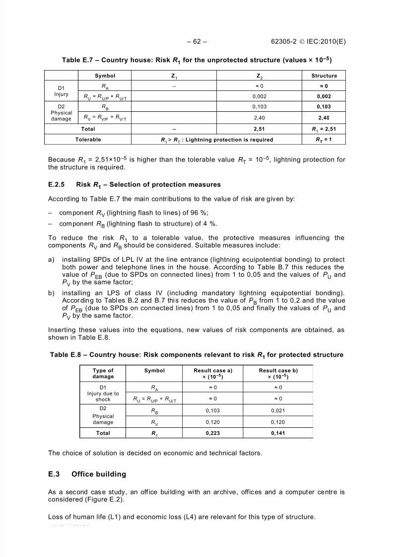
Table E.7 – Country house: Risk R 1 for the unprotected structure (values ´ 10 –5)............... 62
Table E.8 – Country house: Risk components relevant to ri sk R 1 for protected structure .... .. 62
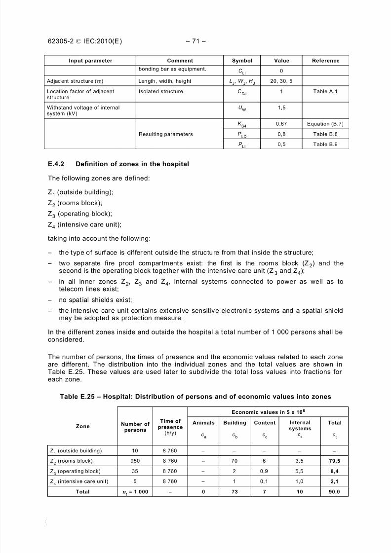
Table E.31 – Hospital: Expected annual number of dangerous events .... .... .... .... ..... .... .... ... 75
Table E.32 – Hospital: Risk R 1 – Values of probability P for the unprotected structure .... ..... 75
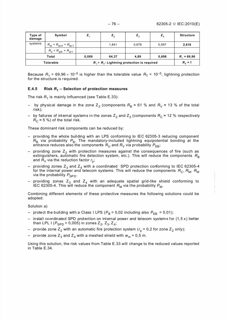
Table E.33 – Hospital: Risk R 1 for the unprotected structure (values ´ 10 –5) ...................... 75
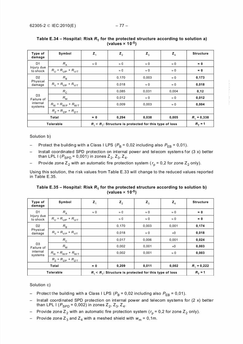
Table E.34 – Hospital: Risk R 1
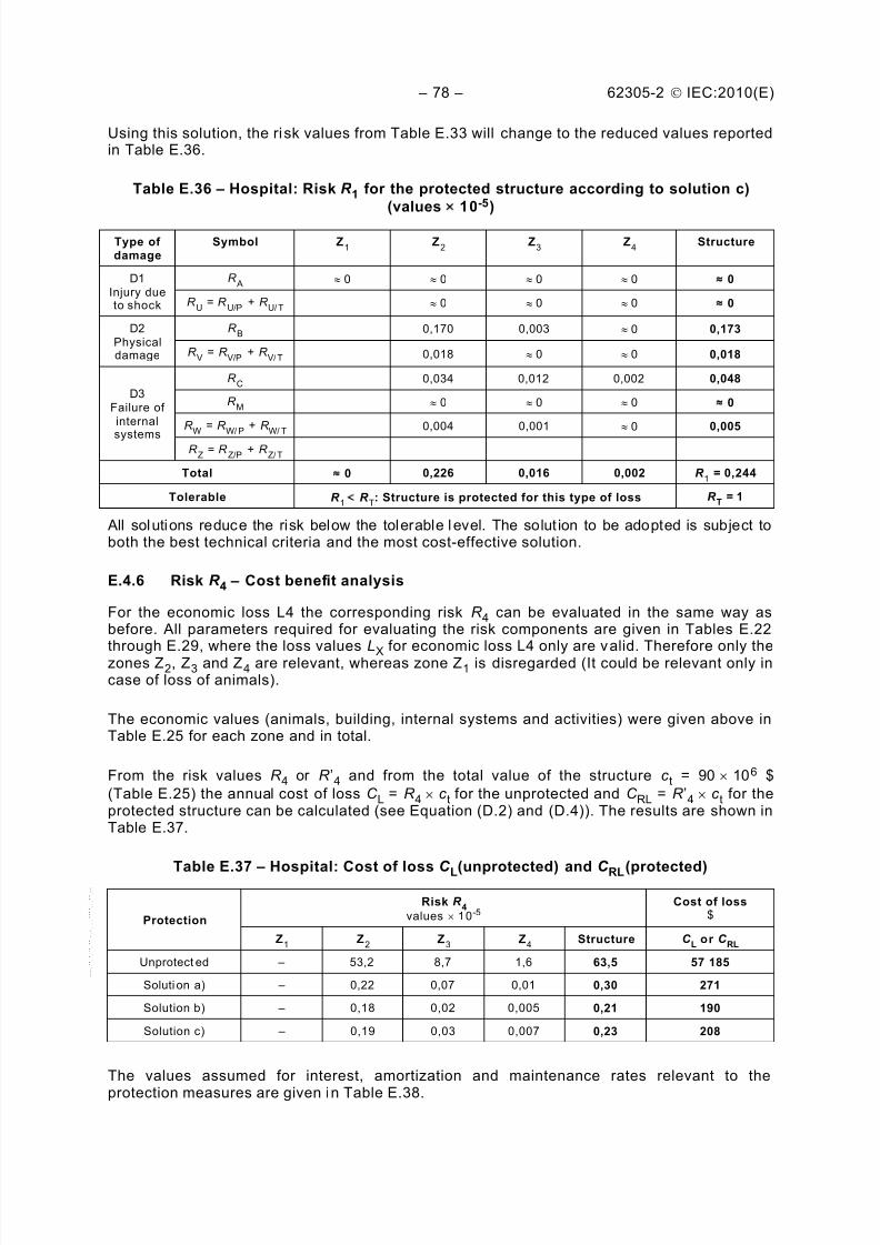
for the protected structure according to solution a)(values ´ 10-5) ............................................................................................................. 77
Table E.35 – Hospital: Risk R 1 for the protected structure according to solution b)(values ´ 10-5) ............................................................................................................. 77
Table E.36 – Hospital: Risk R 1 for the protected structure according to solution c)
INTERNATIONAL ELECTROTECHNICAL COMMISSION _____________
PROTECTION AGAINST LIGHTNING –
Part 2: Risk management
FOREWORD
1) The International Electrotechnical Commission (IEC) is a worldwide organization for standardization comprisingall national electrotechnical committees (IEC National Committees). The object of IEC is to promoteinternational co-operation on all questions concerning standardization in the electrical and electronic fields. Tothis end and in addition to other activities, IEC publishes International Standards, Technical Specifications,Technical Reports, Publicly Available Specifications (PAS) and Guides (hereafter referred to as “IECPublication(s)”). Their preparation is entrusted to technical committees; any IEC National Committee interestedin the subject dealt with may participate in this preparatory work. International, governmental and non-governmental organizations liaising with the IEC also participate in this preparation. IEC collaborates closely
with the International Organization for Standardization (ISO) in accordance with conditions determined byagreement between the two organizations.
2) The formal decisions or agreements of IEC on technical matters express, as nearly as possible, an internationalconsensus of opinion on the relevant subjects since each technical committee has representation from allinterested IEC National Committees.
3) IEC Publications have the form of recommendations for international use and are accepted by IEC NationalCommittees in that sense. While all reasonable efforts are made to ensure that the technical content of IECPublications is accurate, IEC cannot be held responsible for the way in which they are used or for anymisinterpretation by any end user.
4) In order to promote international uniformity, IEC National Committees undertake to apply IEC Publicationstransparently to the maximum extent possible in their national and regional publications. Any divergencebetween any IEC Publication and the corresponding national or regional publication sh all be clearly indicated inthe latter.
5) IEC itself does not provide any attestation of conformity. Independent certification bodies provide conformity
assessment services and, in some areas, access to IEC marks of conformity. IEC is not responsible for anyservices carried out by independent certific ation bodies.
6) All users should ensure that they have the latest edition of this publication.
7) No liability shall attach to IEC or its directors, employees, servants or agents including individual experts andmembers of its technical c ommittees and IEC National Committees for any personal injur y, property damage orother damage of any nature whatsoever, whether direct or indirect, or for costs (including legal fees) andexpenses arising out of the publication, use of, or reliance upon, this IEC Publication or any other IECPublications.
8) Attention is drawn to the Normative references cited in this publication. Use of the referenced publications isindispensable for the correct application of this publication.
9) Attention is drawn to the possibilit y that some of the elements of this IEC Publication may be the subject ofpatent rights. IEC shall not be held responsible for identif ying any or all such patent rights.
International Standard IEC 62305-2 has been prepared by IEC technical committee 81:Lightning protection.
This second edition cancels and replaces the first edition, published in 2006, and constitutesa technical revision.
This edition includes the following significant technical changes with respect to the previousedition:
1) Risk assessment for services connected to structures is excluded from the scope.
2) Injuries of living beings caused by electric shock inside the structure are considered.
3) Tolerable risk of loss of cultural heritage is lowered from 10-3 to 10-4. The value of
tolerable risk of loss of economic value (R T = 10-3
) is introduced, to be used when data forcost/benefit analysis are not available.
4) Extended damage to surroundings structures or to the environment is considered.
5) Improved equations are provided for evaluation of
– col lection areas relevant to flashes nearby a structure,
– col lection areas relevant to flashes to and nearby a line,
– probabil it ies that a f lash can cause damage,
– loss factors even in structures with risk of explosion,
– risk relevant to a zone of a structure,
– cost of loss.
6) Tables are provided to select the relative amount of loss in all cases.
7) Impulse withstand voltage level of equipments was extended down to 1 kV.
The text of this standard is based on the following documents:
FDIS Report on voting
81/371/FDIS 81/381/RVD
Full information on the voting for the approval of this standard can be found in the report onvoting indicated in the above table.
This publication has been drafted in accordance with the ISO/IEC Directives, Part 2.
A list of all the part s in the IEC 62305 series, under the general title Protection againstlightning , can be found on the IEC website.
The committee has decided that the contents of this publication will remain unchanged untilthe stability date indicated on the IEC web site under "http://webstore.iec.ch" in the datarelated to the specific publication. At this date, the publication will be
• reconfirmed,• withdrawn,
• replaced by a revised edition, or
• amended.
A bil ingual version of this standard may be issued at a later date.
IMPORTANT – The 'colour inside' logo on the cover page of this publication indicatesthat it contains colours which are considered to be useful for the correctunderstanding of its contents. Users should therefore print this document using acolour printer.
Lightning flashes to earth may be hazardous to structures and to lines.
The hazard to a structure can result in
– damage to the structure and to its contents,
– fai lure of associated electrical and electroni c systems,
– injury to liv ing beings in or close to the structure.
Consequential effects of the damage and failures may be extended to the surroundings of thestructure or may involve its environment.
To reduce the loss due to lightning, protection measures may be required. Whether they areneeded, and to what extent, should be determined by risk assessment.
The risk, defined in this part of IEC 62305 as the probable average annual loss in a structuredue to lightning flashes, depends on:
– the annual number of lightning flashes inf luencing the structure;
– the probability of damage by one of the inf luencing lightning f lashes;
– the mean amount of consequential loss.
Lightning flashes influencing the structure may be divided into
– flashes terminating on the structure,
– flashes terminating near the structure, direct to connected lines (power, telecom-munication lines,) or near the lines.
Flashes to the structure or a connected line may cause physical damage and life hazards.Flashes near the structure or line as well as flashes to the structure or line may cause failureof electrical and electronic systems due to overvoltages resulting from resistive and inductivecoupling of these systems with the li ghtning current.
Moreover, failures caused by lightning overvoltages in users’ installations and in power supplylines may also generate switching type overvoltages in the installations.
NOTE Malfunctioning of electrical and electronic systems is not covered by the IEC 62305 series. Reference
should be made to IEC 61000-4-5[1 ]1.
The number of lightning flashes influencing the structure depends on the dimensions and the
characteristics of the structure and of the connected lines, on the environmentalcharacteristics of the structure and the lines, as well as on lightning ground flash density inthe region where the structure and the lines are located.
The probability of lightning damage depends on the structure, the connected lines, and thelightning current characteristics, as well as on the type and efficiency of applied protectionmeasures.
The annual mean amount of the consequential loss depends on the extent of damage and theconsequential effects which may occur as result of a lightning flash.
The effect of protection measures results from the features of each protection measure and
may reduce the damage probabilities or the amount of consequential loss.
___________
1 Figures in square brackets refer to the bibliography.--`,,```,,,,````-`-`,,`,,`,`,,`---
The decision to provide lightning protection may be taken regardless of the outcome of riskassessment where there is a desire that there be no avoidable risk.
This part of IEC 62305 is applicable to risk assessment for a structure due to lightning flashesto earth.
Its purpose is to provide a procedure for the evaluation of such a risk. Once an uppertolerable limit for the risk has been selected, this procedure allows the selection ofappropriate protection measures to be adopted to reduce the risk to or below the tolerablelimit.
2 Normative references
The following referenced documents are indispensable for the application of this document.For dated references, only the edition cited applies. For undated references, the latest editionof the referenced document (including any amendments) applies.
IEC 62305-1:2010, Protection against lightning – Part 1: General principles
IEC 62305-3:2010, Protection against lightning – Part 3: Physical damage to structures andlife hazard
IEC 62305-4:2010, Protection against lightning – Part 4: Electrical and electronic systemswithin structures
3 Terms, definitions, symbols and abbreviations
For the purposes of this document, the following terms, definitions, symbols andabbreviations, some of which have already been cited in Part 1 but are repeated here for easeof reading, as well as those given in other parts of IEC 62305, apply.
3.1 Terms and definitions
3.1.1structure to be protected
structure for which protection is required against the effects of lightning in accordance withthis standard
NOTE A structure to be protected may be part of a larg er struc ture.
3.1.2structures with risk of explosionstructures containing solid explosives materials or hazardous zones as determined in
accordance with IEC 60079-10-1[2 ]
and IEC 60079-10-2[3 ]
3.1.3structures dangerous to the environmentstructures which may cause biological, chemical or radioactive emission as a consequence oflightning (such as chemical, petrochemical, nuclear plants, etc.)
3.1.4urban environmentarea with a high density of buildings or densely populated communities with tall buildings
NOTE ’Town centre’ is an example of an urban environment.
3.1.5suburban environmentarea with a medium density of buildings
NOTE ‘Town outskirts’ is an example of a suburban environment.
3.1.6rural environmentarea with a low density of buildings
NOTE ’Countryside’ is an example of a rural environment.
3.1.7rated impulse withstand voltage levelU W impulse withstand voltage assigned by the manufacturer to the equipment or to a part of it,characterizing the specified withstand capability of its insulation against (transient)overvoltages
NOTE For the purposes of this part of IEC 62305, only the withstand voltage between live conductors and earth isconsidered.
3.1.8electrical systemsystem incorporating low voltage power supply components
3.1.9electronic systemsystem incorporating sensitive electronic components such as telecommunication equipment,computer, control and instrumentation systems, radio systems, power electronic installations
3.1.10internal systemselectrical and electronic systems within a structure
3.1.11linepower line or telecommunication line connected to the structure to be protected
3.1.12telecommunication lineslines intended for communication between equipment that may be located in separatestructures, such as phone lines and data lines
3.1.13power linesdistribution lines feeding electrical energy into a structure to power electrical and electronicequipment located there, such as low voltage (LV) or high voltage (HV) electric mains
3.1.14dangerous eventlightning flash to or near the structure to be protected, or to or near a line connected to thestructure to be protected that may cause damage
3.1.15lightning flash to a structurelightning flash striking a structure to be protected
3.1.16
lightning flash near a structurelightning flash striking close enough to a structure to be protected that it may causedangerous overvoltages
3.1.17lightning flash to a linelightning flash striking a line connected to the structure to be protected
3.1.18lightning flash near a linelightning flash striking close enough to a line connected to the structure to be protected that itmay cause dangerous overvoltages
3.1.19number of dangerous events due to flashes to a structureN D expected average annual number of dangerous events due to lightning flashes to a structure
3.1.20number of dangerous events due to flashes to a lineN L expected average annual number of dangerous events due to lightning flashes to a line
3.1.21
number of dangerous events due to flashes near a structureN M expected average annual number of dangerous events due to lightning flashes near astructure
3.1.22number of dangerous events due to flashes near a lineN I expected average annual number of dangerous events due to lightning flashes near a line
3.1.23lightning electromagnetic impulse
LEMPall electromagnetic effects of lightning current via resistive, i nductive and capacitive coupling,which create surges and electromagnetic fields
3.1.24surgetransient created by LEMP that appears as an overvoltage and/or overcurrent
3.1.25nodepoint on a line from which onward surge propagation can be assumed to be neglected
NOTE Examples of nodes are a point on a power line branch distribution at an HV/LV transformer or on a powersubstation, a telecommunication exchange or an equipment (e.g. multiplexer or xDSL equipment) on atelecommunication line.
3.1.26physical damagedamage to a structure (or to its contents) due to mechanical, thermal, chemical or explosiveeffects of lightning
3.1.27injury to living beingspermanent injuries, including loss of life, to people or to animals by electric shock due totouch and step voltages caused by lightning
NOTE Although living beings m ay be injured in other ways, in this part of IE C 62305 the term ‘injury to li vingbeings’ is limited to the thr eat due to electrical shock (type of damage D1).
3.1.28failure of electrical and electronic systemspermanent damage of electrical and electronic systems due to LEMP
3.1.29probability of damageP X probability that a dangerous event will cause damage to or in the structure to be protected
3.1.30lossLX mean amount of loss (humans and goods) consequent on a specified type of damage due to adangerous event, relative to the value (humans and goods) of the structure to be protected
3.1.31risk
Rvalue of probable average annual loss (humans and goods) due to lightning, relative to thetotal value (humans and goods) of the structure to be protected
3.1.32risk componentR X partial risk depending on the source and the type of damage
3.1.33tolerable riskR T maximum value of the risk which can be tolerated for the structure to be protected
3.1.34zone of a structureZS part of a structure with homogeneous characteristics where only one set of parameters isinvolved in assessment of a risk component
3.1.35section of a lineSL part of a line with homogeneous characteristics where only one set of parameters is involvedin the assessment of a risk component
3.1.36lightning protection zoneLPZzone where the lightning electromagnetic environment is defined
NOTE The zone boundaries of an LPZ are not necess arily physical boundaries (e.g. walls, floor and ceiling).
3.1.37lightning protection levelLPL
number related to a set of lightning current parameters values relevant to the probability thatthe associated maximum and minimum design values will not be exceeded in naturallyoccurring lightning
NOTE Lightning protection level is used to design protection measures according to the relevant set of lightningcurrent parameters.
3.1.38protection measuresmeasures to be adopted in the structure to be protected, in order to reduce the risk
3.1.39lightning protection
LPcomplete system for protection of structures against lightning, including their internal systemsand contents, as well as persons, in general consisting of an LPS and SPM
3.1.40lightning protection systemLPScomplete system used to reduce physical damage due to lightning flashes to a structure
NOTE It consists of both external and internal lightning protection systems.
3.1.41LEMP protection measures
SPMmeasures taken to protect internal systems against the effects of LEMP
NOTE This is part of overall lightning protection
3.1.42
magnetic shieldclosed, metallic, grid-like or continuous screen enveloping the structure to be protected, orpart of it, used to reduce failures of electrical and electronic systems
3.1.43lightning protective cable
special cable with increased dielectric strength and whose metallic sheath is in continuouscontact with the soil either directly or by use of conducting plastic covering
3.1.44lightning protective cable ductcable duct of low resistivity in contact with the soil
EXAMPLE Concrete with interconnected structural steel reinforcements or metallic duct.
3.1.45surge protective deviceSPDdevice intended to limit transient overvoltages and divert surge currents; contains at least one
3.1.46coordinated SPD systemSPDs properly selected, coordinated and installed to form a system intended to reducefailures of electrical and electronic systems
3.1.47isolating interfacesdevices which are capable of reducing conducted surges on lines entering the LPZ
NOTE 1 These include isolation transformers with earthed screen between windings, metal-free fibre optic cablesand opto-isolators.
NOTE 2 Insulation withstand characteristics of these devices are suitable for this application intrinsically or viaSPD.
3.1.48lightning equipotential bondingEB
bonding to LPS of separated metallic parts, by direct conductive connections or via surgeprotective devices, to reduce potential differences caused by lightning current
3.1.49zone 0place in which an explosive atmosphere consisting of a mixture of air and flammablesubstances in the form of gas, vapour or mist is present continuously or for long periods orfrequently
(IEC 60050-426:2008, 426-03-03, modified)[5 ]
3.1.50zone 1
place in which an explosive atmosphere consisting of a mixture of air and flammablesubstances in the form of gas, vapour or mist is likely to occur in normal operationoccasionally
(IEC 60050-426:2008, 426-03-04, modified)[5]
3.1.51zone 2place in which an explosive atmosphere consisting of a mixture of air and flammablesubstances in the form of gas, vapour or mist is not likely to occur in normal operation but, if itdoes occur, will persist for a short period only
NOTE 1 In this definition, the word "persist" means the total time for which the flammable atmosphere will exist.This will normally comprise the total of the duration of the release, plus the time taken for the flammableatmosphere to disperse after the r elease has stopped.
NOTE 2 Indications of the frequency of the occurrence and duration may be taken from codes relating to specificindustries or applications.
(IEC 60050-426:2008, 426-03-05, modified)[5 ]
3.1.52zone 20place in which an explosive atmosphere, in the form of a cloud of combustible dust in air, ispresent continuously, or for long periods, or f requently
3.1.53zone 21place in which an explosive atmosphere, in the form of a cloud of combustible dust in air, islikely to occur in normal operation occasionally
(IEC 60079-10-2:2009, 6.2, modified)[3]
3.1.54zone 22place in which an explosive atmosphere, in the form of a cloud of combustible dust in air, isnot likely to occur in normal operation but, if it does occur, will persist for a short period only
(IEC 60079-10-2:2009, 6.2, modified) [3]
3.2 Symbols and abbreviations
a Amortization rate ............. ............. ............. ............. ............. ............. ...... Annex D
AD Collection area for flashes to an isolated structure ............ ............. ............. . A.2.1.1 ADJ Collection area for flashes to an adjacent structure ............. ............. ............. .. A.2.5
AD' Collection area attributed to an elevated roof protrusion ....... .... .... .... .... .... ... A.2.1.2
AI Collection area for flashes near a line ............. ............. ............. ............. ........... A.5
AL Collection area for flashes to a line ............ ............. ............. ............. ............. .. A.4
AM Collection area for flashes striking near the structure ...... ............. ............. ........ A.3
B Building ............ ............. ............. ............. ............. ............. ............. ............. .. A.2
C D Location factor............... ............. ............. ............. ............. ............. ...... Table A.1
C DJ Location factor of an adjacent structure......................................................... A.2.5
C E Environmental factor ............. ............. ............. ............. ............. ............. Table A.4C I Installation factor of the line ........... ............. ............. ............. ............. ..... Table A.2
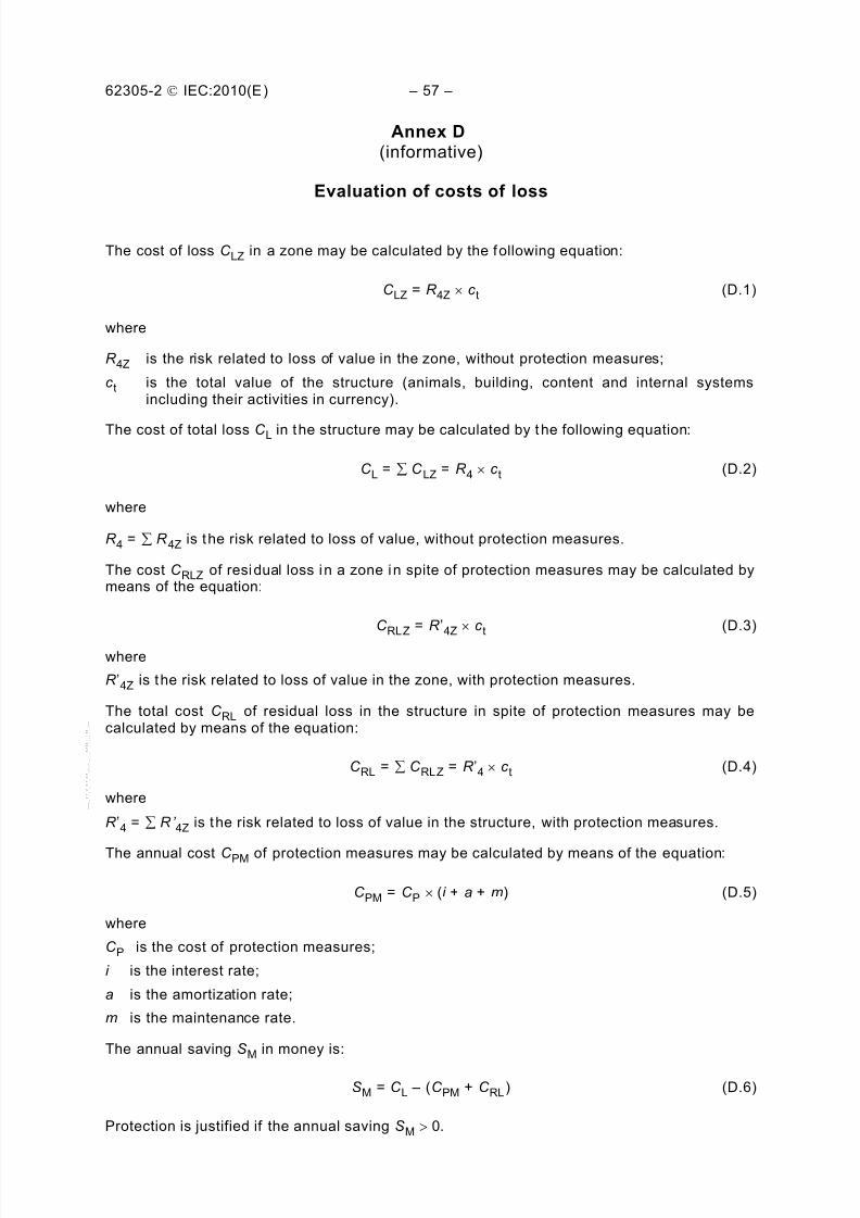
C L Annual cost of total loss in absence of protection measures .... .... .... ..... . 5.5; Annex D
C LD Factor depending on shielding, grounding and isolation conditions
of the line for flashes to a line ............. ............. ............. ............. ............. ..Annex B
C LI Factor depending on shielding, grounding and isolation conditions
of the line for flashes near a line .................... ............. ............. ............. ....Annex B
C LZ Cost of loss in a zone………………………………………………………………….Annex D
C P Cost of protection measures ............. ............. ............. ............. ............. ... Annex D
C PM Annual cost of selected protection measures ............ ............. ............. . 5.5; Annex D
C RL Annual cost of residual loss ............ ............. ............. ............. ............ 5.5; Annex D
C RLZ Cost of residual loss in a zone.………………………………………………………Annex DC T Line type factor for a HV/LV transformer on the line ............. ............. ........ Table A.3
c a Value of the animals in the zone, in currency ............. ............. ............. ............. C.6
c b Value of the building relevant to the zone, in currency ............ ............. ............. . C.6
c c Value of the content in the zone, in currency ............ ............. ............. ............. . C.6
c e Total value of goods in dangerous place outside the structure, in currency ………..C.6
c s Value of the internal systems (including their activities) in the zone,
hz Factor increasing the loss when a special hazard is present .... .... .... ..... .... .. Table C.6
H Height of the structure ............. ............. ............. ............. ............. ............ A.2.1.1
H J Height of the adjacent structure..................................................................... A.2.5
i Interest rate ............ ............. ............. ............. ............. ............. ............. . Annex D
K MS Factor relevant to the performance of protection measures against LEMP .... .... .... B.5
K S1 Factor relevant to the screening effectiveness of the structure............. ............. ... B.5
K S2 Factor relevant to the screening effectiveness of shields internal to the structure .. ... . B.5
K S3 Factor relevant to the characteristics of internal wiring..................... ............. ...... B.5
K S4 Factor relevant to the impulse withstand voltage of a system............ ............. ...... B.5
L Length of structure ............ ............. ............. ............. ............. ............. ....... A.2.1.1
LJ Length of the adjacent structure ............. ............. ............. ............. ............. ... A.2.5
L A Loss due to injury to living beings by electric shock (flashes to structure)………….6.2
LB Loss in a structure related to physical damage (flashes to structure) .... .... .... .. .. ....6.2LL Length of line section ............ ............. ............. ............. ............. ............. ......... A.4
LC Loss related to failure of internal systems (flashes to structure) .... .... .... .... .... ..... .. 6.2
LE Addit ional loss when the damage inv olves surrounding structures…………….C.3; C.6
LF Loss in a structure due to physical damage .... .... .... .... .... ... Tables C.2, C8, C10, C12
LFE Loss due to physical damage outside the structure……………………………… C.3; C.6
LFT Total loss due to physical damage in and outside the structure………………..C.3; C.6
LM Loss related to failure of internal systems (flashes near structure) .... .... .... .... .... ... 6.3
LO Loss in a structure due to failure of internal systems .... .... .... .... . Tables C.2, C8, C12
LT Loss due to injury by electric shock ............ ............. ............. ........ Tables C.2, C12
LU Loss due to injury of living beings by electric shock (flashes to line) .... .... .... .... .... . 6.4
LV Loss in a structure due to physical damage (flashes to line) ............ ............. ....... 6.4LW Loss related to failure of internal systems (flashes to line) ............ ............. ......... 6.4
LX Loss consequent to damages relevant to structure ............. ............. ............. ...... 6.1
LZ Loss related to failure of internal systems (flashes near a line) .... .... ..... .... .... ..... .. 6.5
L1 Loss of human life....................... ............. ............. ............. ............. ............. 4.1.3
L2 Loss of service to the public ............ ............. ............. ............. ............. .......... 4.1.3
L3 Loss of cultural heritage ............ ............. ............. ............. ............. ............. .. 4.1.3
L4 Loss of economic value ............. ............. ............. ............. ............. ............. .. 4.1.3
m Maintenance rate ............. ............. ............. ............. ............. ............. ...... Annex D
N x Number of dangerous events per annum ........... ............. ............. ............. ......... 6.1N D Number of dangerous events due to flashes to structure………………………….A.2.4 N DJ Number of dangerous events due to flashes to adjacent structure.. .... .... .... .... ... A.2.5
N G Lightning ground f lash density ............. ............. ............. ............. ............. ......... A.1
N I Number of dangerous events due to flashes near a line ............ ............. ............ A.5
N L Number of dangerous events due to flashes to a line ............ ............. ............. ... A.4
N M Number of dangerous events due to flashes near a structure....... .... ..... .... .... ..... .. A.3
nz Number of possible endangered persons (victims or users not served) ..... .... . C.3; C.4
nt Expected total number of persons (or users served) ........... ............. ............ C.3; C.4
P Probability of damage...................... ............. ............. ............. ............. .....Annex B
P A Probability of injury to living beings by electric shock(flashes to a structure) …………………………………………………………………6.2; B.2
P B Probability of physical damage to a structure (flashes to a structure) .... .... .. Table B.2
P C Probability of failure of internal systems (flashes to a structure) .... .... .... .... .... 6.2; B.4
P EB Probability reducing P U and P V depending on line characteristics and
withstand voltage of equipment when EB is installed .... .... .... .... .... .... ..... .... .. Table B.7
P LD Probability reducing P U, P V and P W depending on line characteristics
and withstand voltage of equipment (flashes to connected line)............. .......... . Table B.8
P LI Probability reducing P Z depending on line characteristics and
withstand voltage of equipment (flashes near a connected line) ...... .......... ....... Table B.9P M Probability of failure of internal systems (flashes near a structure) .... .... .... .... 6.3; B 5
P MS Probability reducing P M depending on shielding, wiri ng and
withstand voltage of equipment ............. ............. ............. ............. ............. ....... B.5
P SPD Probability reducing P C, P M, P W and P Z when a coordinated SPD
system is installed .................................................................................... Table B.3
P TA Probability reducing P A depending on protection measures
against touch and step voltages……………………………………………………Table B.1
P U Probability of injury to living beings by electric shock
(flashes to a connected line) .... .... .... .... ………………………………………………6.4; B.6
P V Probability of physical damage to a structure
(flashes to a connected line)……………………………………………………………..6.4; B.7P W Probability of failure of internal systems (flashes to connected line) .... .... .... .... 6.4; B.8
P X Probability of damage relevant to a structure ............. ............. ............. ............. . 6.1
P Z Probability of failure of internal systems
(flashes near a connected line)……………………………………………………….6.5; B.9
r t Reduction factor associated with the type of surface ...... ............. ............. .......... C.3
r f Factor reducing loss depending on risk of fire ........... ............. ............. ............. .. C.3
r p Factor reducing the loss due to provisions against fire ............ ............. ............. .. C.3
R A Risk component (injury to living beings – flashes to structure) .... .... .... .... .... .... .. 4.2.2
R B Risk component (physical damage to a structure – flashes to a structure) .... ..... . 4.2.2R C Risk component (failure of internal systems –flashes to structure) .... .... .... .... .... 4.2.2
R M Risk component (failure of internal systems – flashes near structure) .... ..... .... 4.2.3
R S Shield resistance per unit length of a cable................... ............. ............. .. Table B.8
R T Tolerable risk ............ ............. ............. ............. ............. ............. ....... 5.3; Table 4
R U Risk component (injury to living being – flashes to connected line) ..... .... .... ..... . 4.2.4
R V Risk component (physical damage to structure – flashes to connected line) ..... .. 4.2.4
R W Risk component (failure of internal systems – flashes to connected line) ........ ......... 4.2.4
R X Risk component for a structure ............. ............. ............. ............. ............. ........ 6.1
R Z Risk component (failure of internal systems – flashes near a line)..................... 4.2.5
R 1 Risk of loss of human life in a structure ............. ............. ............. ............. ...... 4.2.1
R 2 Risk of loss of service to the public in a structure ............ ............. ............. ...... 4.2.1R 3 Risk of loss of cultural heritage in a structure............. ............. ............. ........... 4.2.1
R 4 Risk of loss of economic value in a structure ........... ............. ............. ............. 4.2.1
R ’4 Risk R 4 when protection measures are adopted ............ ............. ............. ... Annex D
S Structure..................................................................................................... A.2.2
SM Annual saving of money ............ ............. ............. ............. ............. .......... Annex D
SL Section of a line.............................................................................................. 6.8
S1 Source of damage – Flashes to a structure..................................................... 4.1.1
S2 Source of damage – Flashes near a structure ............. ............. ............. .......... 4.1.1
S3 Source of damage – Flashes to a line ............. ............. ............. ............. ........ 4.1.1
S4 Source of damage – Flashes near a line............ ............. ............. ............. ...... 4.1.1
t e Time in hours per year of presence of people in a dangerous
place outside the structure………………………………………………………………….C.3
t z Time in hours per year that persons are present in a dangerous place ...... ..... .... .. C.2--
T D Thunderstorm days per year ............. ............. ............. ............. ............. ........... A.1
U W Rated impulse withstand voltage of a system ............ ............. ............. ............. .. B.5
w m Mesh width..................................................................................................... B.5W Width of structure ............ ............. ............. ............. ............. ............. ........ A.2.1.1
W J Width of the adjacent structure ............ ............. ............. ............. ............. ...... A.2.5
X Subscript identifying the relevant risk component……………………………………….6.1
ZS Zones of a structure ............ ............. ............. ............. ............. ............. ........... 6.7
4 Explanation of terms
4.1 Damage and loss
4.1.1 Source of damage
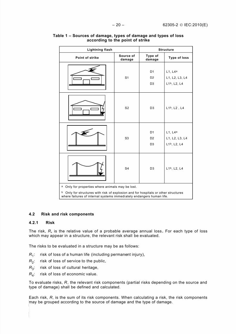
The lightning current is the primary source of damage. The following sources aredistinguished by the point of strike (see Table 1):
S1: flashes to a structure,
S2: flashes near a structure,
S3: flashes to a line,
S4: flashes near a line.
4.1.2 Types of damage
A lightning flash may cause damage depending on the characteristics of the structure to be
protected. Some of the most important characteristics are: type of construction, contents andapplication, type of service and protection measures provided.
For practical applications of this risk assessment, it is useful to distinguish between threebasic types of damage which can appear as the consequence of lightning flashes. They areas follows (see Table 1):
D1: injury to living beings by electric shock,
D2: physical damage,
D3 : failure of electrical and electronic systems.
The damage to a structure due to lightning may be limited to a part of the structure or may
extend to the entire structure. It may also involve surrounding structures or the environment(e.g. chemical or radioactive emissions).
4.1.3 Types of loss
Each type of damage, alone or in combination with others, may produce a differentconsequential loss in the structure to be protected. The type of loss that may appear, dependson the characteristics of the structure itself and its content. The following types of loss shallbe taken into account (see Table 1):
L1: loss of human life (including permanent injury);
L2: loss of service to the public;
L3: loss of cultural heritage;
L4: loss of economic value (structure, content, and loss of activity).
Table 1 – Sources of damage, types of damage and types of lossaccording to the point of strike
Lightning flash Structure
Point of strike
Source of
damage
Type of
damage Type of loss
S1
D1
D2
D3
L1, L4a
L1, L2, L3, L4
L1b, L2, L4
S2 D3 L1b, L2 , L4
S3
D1
D2
D3
L1, L4a
L1, L2, L3, L4
L1b, L2, L4
S4 D3 L1b, L2, L4
a Only for properties where animals may be lost.
b Only for structures with risk of explosion and for hospitals or other structureswhere failures of internal systems immedi ately endangers human life.
4.2 Risk and risk components
4.2.1 Risk
The risk, R , is the relative value of a probable average annual loss. For each type of losswhich may appear in a structure, the relevant risk shall be evaluated.
The risks to be evaluated in a structure may be as follows:
R 1: risk of loss of a human life (including permanent injury),
R 2: risk of loss of service to the public,
R 3: risk of loss of cultural heritage,
R 4: risk of loss of economic value.
To evaluate risks, R , the relevant risk components (partial risks depending on the source andtype of damage) shall be defined and calculated.
Each risk, R , is the sum of its risk components. When calculating a risk, the risk componentsmay be grouped according to the source of damage and the type of damage.
4.2.2 Risk components for a structure due to flashes to the structure
R A: Component related to injury to living beings caused by electric shock due to touch andstep voltages inside the structure and outside in the zones up to 3 m around down-conductors. Loss of type L1 and, in the case of structures holding livestock, loss of type
L4 with possible loss of animals may also arise.
NOTE In special structures, people may be endangered by direct strikes (e.g. top level of garage parkingor stadiums). These cases may also be c onsidered using the principles of this part of IEC 62305.
R B: Component related to physical damage caused by dangerous sparking inside thestructure triggering fire or explosion which may also endanger the environment. Alltypes of loss (L1, L2, L3 and L4) may arise.
R C: Component related to failure of internal systems caused by LEMP. Loss of type L2 andL4 could occur in all cases along with type L1 in the case of structures with risk ofexplosion, and hospitals or other structures where failure of internal systemsimmediately endangers human life.
4.2.3 Risk component for a structure due to flashes near the structure
R M: Component related to failure of internal systems caused by LEMP. Loss of type L2 andL4 could occur in all cases, along with type L1 in the case of structures with risk ofexplosion, and hospitals or other structures where failure of internal systemsimmediately endangers human life.
4.2.4 Risk components for a structure due to flashes to a line connected to thestructure
R U: Component related to injury to living beings caused by electric shock due to touchvoltage inside the structure. Loss of type L1 and, in the case of agricultural properties,
losses of type L4 with possible loss of animals could also occur.R V: Component related to physical damage (fire or explosion triggered by dangerous
sparking between external installation and metallic parts generally at the entrance pointof the line into the structure) due to lightning current transmitted through or alongincoming lines. All types of loss (L1, L2, L3, L4) may occur.
R W : Component related to failure of internal systems caused by overvoltages induced onincoming lines and transmitted to the structure. Loss of type L2 and L4 could occur in allcases, along with type L1 in the case of structures with risk of explosion, and hospitalsor other structures where failure of internal systems immediately endangers human life.
NOTE 1 The lines taken into account in this assessment are only the lines entering the structure.
NOTE 2 Lightning flashes to or near pipes are not considered as a source of damage based on the bonding ofpipes to an equipotential bonding bar. If an equipotential bonding bar is not provided, such a threat should also be
considered.
4.2.5 Risk component for a structure due to flashes near a line connected to thestructure
R Z: Component related to failure of internal systems caused by overvoltages induced onincoming lines and transmitted to the structure. Loss of type L2 and L4 could occur in allcases, along with type L1 in the case of structures with risk of explosion, and hospitalsor other structures where failure of internal systems immediately endanger human life.
NOTE 1 Lines taken into account in this assessment are only the lines entering the structure.
NOTE 2 Lightning flashes to or near pipes are not considered as a source of damage based on the bonding ofpipes to an equipotential bonding bar. If an equipotential bonding bar is not provided, such a threat should also beconsidered.
Risk components to be considered for each type of loss in a structure are listed below:
R 1: Risk of loss of human life:
R 1 = R A1 + R B1 + R C11) + R M1
1) + R U1 + R V1 + R W11) + R Z1
1) (1)
1) Only for structures with risk of explosion and for hospitals with life-saving electrical equipment or otherstructures when failure of internal systems imm ediately endangers human life.
R 2: Risk of loss of service to the public:
R 2 = R B2 + R C2 + R M2 + R V2 + R W2 + R Z2 (2)
R 3: Risk of loss of cultural heritage:
R 3 = R B3 + R V3 (3)
R 4: Risk of loss of economic value:
R 4 = R A42) + R B4 + R C4 + R M4 + R U4
2) + R V4 + R W4 + R Z4 (4)
2) Only for properties where animals may be lost.
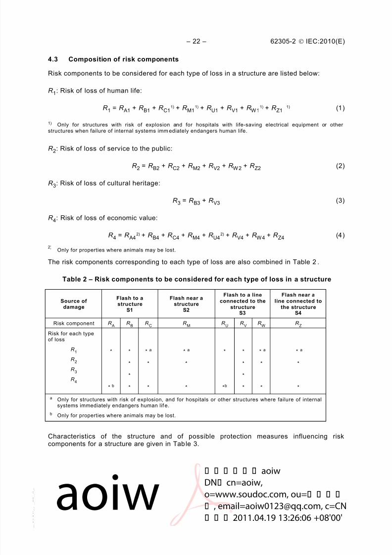
The risk components corresponding to each type of loss are also combined in Table 2.
Table 2 – Risk components to be considered for each type of loss in a structure
Source ofdamage
Flash to astructure
S1
Flash near astructure
S2
Flash to a lineconnected to the
structureS3
Flash near aline connected to
the structureS4
Risk component R A
R B R
C R
M R
U R
V R
W R
Z
Risk for each typeof loss
R 1
R 2
R 3
R 4
*
* b
*
*
*
*
* a
*
*
* a
*
*
*
*b
*
*
*
*
* a
*
*
* a
*
*
a Only for structures with risk of explosion, and for hospitals or other structures where failure of internalsystems immediately endangers human lif e.
b Only for properties where animals may be lost.
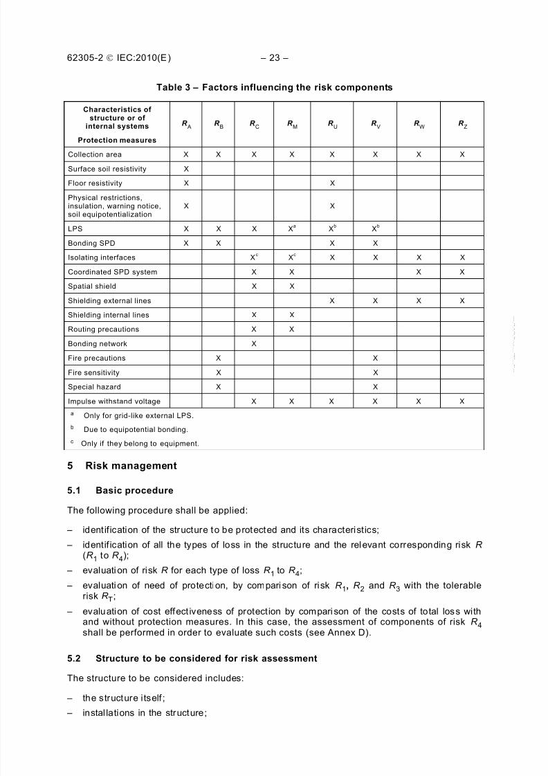
Characteristics of the structure and of possible protection measures influencing riskcomponents for a structure are given in Table 3.
– identification of the structure to be protected and its characteristics;
– identif ication of all the types of loss in the structure and the relevant corresponding risk R (R 1 to R 4);
– evaluati on of risk R for each type of loss R 1 to R 4;
– evaluati on of need of protection, by compari son of risk R 1, R 2 and R 3 with the tolerablerisk R T;
– evaluation of cost effect iveness of protection by compari son of the costs of total loss withand without protection measures. In this case, the assessment of components of risk R 4shall be performed in order to evaluate such costs (see Annex D).
5.2 Structure to be considered for risk assessment
– persons in the structure or in the zones up to 3 m from the outside of the structure;
– env ironment affected by damage to the structure.
Protection does not include connected lines outside of the structure.
NOTE The structure to be considered may be subdivided into several zones (see 6.7).
5.3 Tolerable risk R T
It is the responsibility of the authority having jurisdiction to identify the value of tolerable risk.
Representative values of tolerable risk R T, where lightning flashes involve loss of human lifeor loss of social or cultural values, are given in Table 4.
Table 4 – Typical values of tolerable risk R T
Types of loss R T (y –1 )
L1 Loss of human life or permanent injuries 10 –5
L2 Loss of service to the public 10 –3
L3 Loss of cultural heritage 10 –4
In principle, for loss of economic value (L4), the route to be followed is the cost/benefitcomparison given in Annex D. If the data for this analysis are not available the representativevalue of tolerable risk R T = 10-3 may be used.
5.4 Specific procedure to evaluate the need of protection
According to IEC 62305-1, risks R 1, R 2 and R 3 shall be considered in the evaluation of theneed of protection against lightning.
For each risk to be considered the following steps shall be taken:
– identif ication of the components R X which make up the risk;
– calculation of the ident ified risk components R X;
– calculation of the total risk R (see 4.3);
– identif ication of the tolerable risk R T;
– compari son of the risk R with the tolerable value R T.
If R £ R T, lightning protection is not necessary.
If R > R T, protection measures shall be adopted in order to reduce R £ R T for all risks towhich the structure is subjected.
The procedure to evaluate the need for protection is given in Figure 1.
NOTE 1 In cases where the risk cannot be reduced to a tolerable level, the site owner should be informed and thehighest level of protection provided to the installation.
NOTE 2 Where protection against lightning is required by the authority having jurisdiction for structures with a riskof explosion, at least a class II LPS should be adopted. Exceptions to the use of lightning protection level II may be
allowed when technically justified and authorized by the authority having jurisdiction. For example, the use oflightning protection level I is allowed in all cases, especially in those cases where the environments or contentswithin the structure are exceptionally sensitive to the effects of lightning. In addition, authorities having jurisdictionmay choose to allow lightning protecti on level III systems where the infrequency of lightning activity and/or theinsensitivity of the contents of the structure warrants it.
NOTE 3 When the damage to a structure due to li ghtning may also involve surr ounding structures or theenvironment (e.g. chemical or radioactive emissions), additional protection measures for the structure andmeasures appropriate for these zones may be requested by the authorities having juris diction.
5.5 Procedure to evaluate the cost effectiveness of protection
Besides the need for lightning protection of a structure, it may be useful to ascertain theeconomic benefits of installing protection measures in order to reduce the economic loss L4.
The assessment of components of risk R 4 allows the user to evaluate the cost of theeconomic loss with and without the adopted protection measures (see Annex D).
The procedure to ascertain the cost effectiveness of protection requires:
– identification of the components R X which make up the risk R 4;
– calculation of the identified risk components R X in absence of new/additional protectionmeasures;
– calculation of the annual cost of loss due to each risk component R X;
– calculation of the annual cost C L of total loss in the absence of protection measures;
– adoption of selected protection measures;
– calculation of risk components R X with selected protection measures present;
– calculation of the annual cost of residual loss due to each risk component R X in theprotected structure;
– calculation of the total annual cost C RL of residual loss with selected protection measurespresent;
– calculation of the annual cost C PM of selected protection measures;
– comparison of costs.
If C L < C RL + C PM , lightning protection may be deemed not to be cost effective.
If C L ³ C RL + C PM , protection measures may prove to save money over the life of thestructure.
The procedure to evaluate the cost-effectiveness of protection is outlined in Figure 2.
It may be useful to evaluate some variants of combination of protection measures to find theoptimal solution regarding the cost effectiveness.
Protection measures are directed to reducing the risk according to the type of damage.
Protection measures shall be considered effective only if they conform to the requirements ofthe following relevant standards:
– IEC 62305-3 for protection against injury to living beings and physical damage in astructure;
– IEC 62305-4 for protection against failure of electrical and electronic systems.
5.7 Selection of protection measures
The selection of the most suitable protection measures shall be made by the designeraccording to the share of each risk component in the total risk R and according to thetechnical and economic aspects of the different protection measures.
Critical parameters shall be identified to determine the more efficient measure to reduce therisk R .
For each type of loss, there is a number of protection measures which, individually or incombination, make the condition R £ R T. The solution to be adopted shall be selected withallowance for technical and economic aspects. A simplified procedure for selection ofprotective measures is given in the flow diagram of Figure 1. In any case, the installer orplanner should identify the most critical risk components and reduce them, also taking intoaccount economic aspects.
6 Assessment of risk components
6.1 Basic equation
Each risk component R A, R B, R C, R M, R U, R V, R W and R Z, as described in 4.2.2, 4.2.3, 4.2.4and 4.2.5 may be expressed by the following general equation:
R X = N X ´ P X ´ LX (5)
where
N X is the number of dangerous events per annum (see also Annex A);
P X is the probability of damage to a structure (see also Annex B);LX is the consequent loss (see also Annex C).
The number N X of dangerous events is affected by lightning ground flash density (N G) and bythe physical characteristics of the structure to be protected, its surroundings, connected linesand the soil.
The probability of damage P X is affected by characteristics of the structure to be protected,the connected lines and the protection measures provided.
The consequent loss LX is affected by the use to which the structure is assigned, theattendance of persons, the type of service provided to public, the value of goods affected by
the damage and the measures provided to limit the amount of loss.
NOTE When the damage to a structure due to lightning may also involve surrounding structures or theenvironment (e.g. chemical or radioactive emiss ions), the consequent loss should be added to the value of LX.
6.2 Assessment of risk components due to flashes to the structure (S1)
For evaluation of risk components related to lightning flashes to the structure, the followingrelationships apply:
– component related to injury to l iving beings by electric shock (D1)
R A = N D ´ P A ´ L A (6)
– component related to physical damage (D2)
R B = N D ´ P B ´ LB (7)
– component related to failure of internal systems (D3)
R C = N D ´ P C ´ LC (8)
Parameters to assess these risk components are given in Table 5.
6.3 Assessment of the risk component due to flashes near the structure (S2)
For evaluation of the risk component related to lightning flashes near the structure, thefollowing relationship applies:
– component related to failure of internal systems (D3)
R M = N M ´ P M ´ LM (9)
Parameters to assess this risk component are given in Table 5.
6.4 Assessment of risk components due to flashes to a line connected to thestructure (S3)
For evaluation of the risk components related to lightning flashes to an incoming line, thefollowing relationships apply:
– component related to injury to liv ing beings by electric shock (D1)
R U = (N L + N DJ) ´ P U ´ LU (10)
– component related to physical damage (D2)
R V = (N L + N DJ) ´ P V ´ LV (11)
– component related to failure of internal systems (D3)
R W = (N L + N DJ) ´ P W ´ LW (12)
NOTE 1 In many cases N DJ may be negl ected.
Parameters to assess these risk components are given in Table 5.
If the line has more than one section (see 6.8), the values of R U, R V and R W are the sum ofthe R U, R V and R W values relevant to each section of the line. The sections to be consideredare those between the structure and the first node.
In the case of a structure with more than one connected line with different routing, thecalculations shall be performed for each line.
In the case of a structure with more than one connected line with the same routing, thecalculations shall be performed only for the line with the worst characteristics, i.e. the line withthe highest values of N L and N I connected to the internal system with the lowest value of U W(telecom line versus power line, unscreened line versus screened line, LV power line versusHV power line with HV/LV transformer, etc.).
NOTE 2 In the case of lines for which there is an overlapping of the collection area, the overlapping area shouldbe considered only once.
6.5 Assessment of risk component due to flashes near a line connected to thestructure (S4)
For evaluation of the risk component related to lightning flashes near a line connected to thestructure, the following relationship applies:
– component related to fai lure of internal systems (D3)
R Z = N I ´ P Z ´ LZ (13)
Parameters to assess this risk component are given in Tabl e 5.
If the line has more than one section (see 6.8), the value of R Z is the sum of the R Z components relevant to each section of the line. The sections to be considered are thosebetween the structure and the first node.
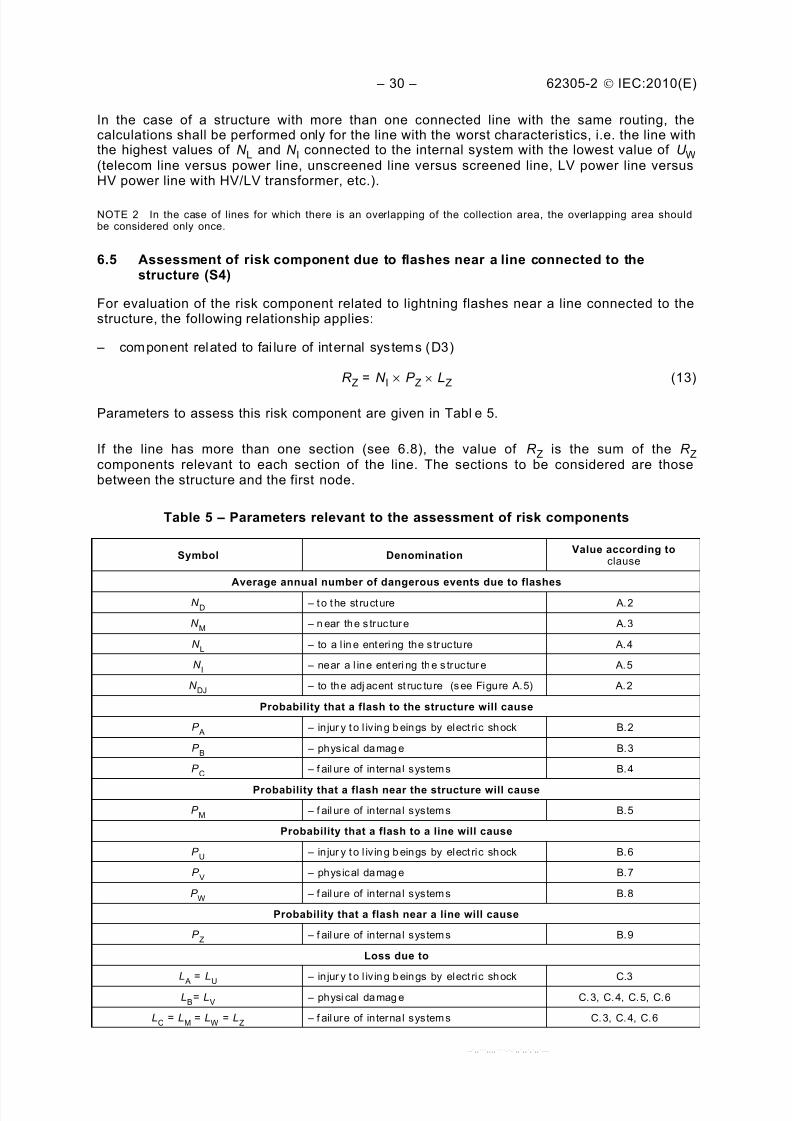
Table 5 – Parameters relevant to the assessment of risk components
Symbol DenominationValue according to
clause
Average annual number of dangerous events due to flashes
N D
– t o t he st ructure A.2
N M
– n ear the s truc ture A.3
N L – to a l in e entering the s tructure A.4
N I – near a l ine enteri ng the s tructur e A.5
N DJ
– to the adj acent st ruc ture (see Figure A.5) A.2
Probability that a flash to the structure will cause
P A
– in jur y t o l iv in g b eings by elect ric shock B.2
P B – physical damag e B.3
P C
– f ail ure of in ternal systems B.4
Probability that a flash near the structure will cause
P M
– f ail ure of in ternal systems B.5
Probability that a flash to a line will cause
P U
– in jur y t o l iv in g b eings by elect ric shock B.6
P V – physical damag e B.7
P W
– f ail ure of in ternal systems B.8
Probability that a flash near a line will cause
P Z – f ail ure of in ternal systems B.9
Loss due to
L A
= LU
– in jur y t o l iv in g b eings by elect ric shock C.3
In the case of a structure with more than one connected line with different routing, thecalculations shall be performed for each line.
In the case of a structure with more than one connected line with the same routing, thecalculations shall be performed only for the line with the worst characteristics, i.e. the line with
the highest values of N L and N I connected to the internal system with the lowest value of U W(telecom line versus power line, unscreened line versus screened line, LV power line versusHV power line with HV/LV transformer, etc.)
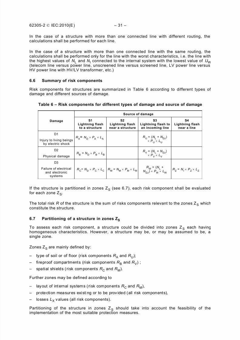
6.6 Summary of risk components
Risk components for structures are summarized in Table 6 according to different types ofdamage and different sources of damage.
Table 6 – Risk components for different types of damage and source of damage
Damage
Source of damage
S1Lightning flashto a structure
S2Lightning flashnear a structure
S3Lightning flash toan incoming line
S4Lightning flash
near a line
D1
Injury to living beingsby electric shock
R A
= N D P
A L
A R
U = (N L + N
DJ)
´ P U
´ LU
D2
Physical damageR
B = N
D ´ P
B ´ L
B
R V = (N
L + N DJ
)
´ P V
´ LV
D3
Failure of electricaland electronic
systems
R C
= N D
´ P C
´ LC
R M = N
M ´ P
M ´ L
M
R W
= (N L +
N DJ
) ´ P W
´ LW
R
Z = N
I ´ P
Z ´ L
Z
If the structure is partitioned in zones ZS (see 6.7), each risk component shall be evaluatedfor each zone ZS.
The total risk R of the structure is the sum of risks components relevant to the zones ZS whichconstitute the structure.
6.7 Partitioning of a structure in zones ZS
To assess each risk component, a structure could be divided into zones ZS each havinghomogeneous characteristics. However, a structure may be, or may be assumed to be, a
single zone.
Zones ZS are mainly defined by:
– type of soil or of floor (r isk components R A and R U);
– fi reproof compartments (ri sk components R B and R V) ;
– spatial shields ( risk components R C and R M).
Further zones may be defined according to
– layout of internal systems (risk components R C and R M),
– protection measures existing or to be prov ided (all risk components),
– losses LX values (all risk components).
Partitioning of the structure in zones ZS should take into account the feasibility of theimplementation of the most suitable protection measures.
according to this part of IEC 62305 may be LPZ in li ne with IEC 62305-4. However they may alsobe different from LPZs.
6.8 Partitioning of a line into sections SL
To assess the risk components due to a flash to or near a line, the line could be divided into
sections SL. However a line may be, or may be assumed to be, a single section.
For all risk components, sections SL are mainly defined by
– type of line (aerial or buried),
– factors affecting the col lection area (C D, C E, C T),
– characteristics of line (shielded or unshielded, shield resistance).
If more than one value of a parameter exists in a section, the value leading to the highestvalue of risk is to be assumed.
6.9 Assessment of risk components in a structure with zones ZS 6.9.1 General criteria
For the evaluation of risk components and the selection of the relevant parameters involved,the following rules apply:
– parameters relevant to the number N of dangerous events shall be evaluated according to Annex A;
– parameters relevant to the probabil ity P of damage shall be evaluated according to Annex B.
Moreover:
– for components R A, R B, R U, R V, R W and R Z, only one value is to be fixed in each zone foreach parameter involved. Where more than one value is applicable, the highest one shallbe chosen.
– for components R C and R M, if more than one internal system is involved in a zone, valuesof P C and P M are given by:
P C = 1 – (1 – P C1) ´ (1 – P C2) ´ (1 – P C3) (14)
P M = 1 – (1 – P M1) ´ (1 – P M2) ´ (1 – P M3) (15)
where P Ci, and P Mi are parameters relevant to internal system i =1, 2, 3,…
– parameters relevant to the amount L of loss shall be evaluated according to Annex C.
With the exception made for P C and P M, if more than one value of any other parameter existsin a zone, the value of the parameter leading to the highest value of risk is to be assumed.
6.9.2 Single zone structure
In this case only one zone ZS made up of the entire structure is defined. The risk R is the sumof risk components R X in this zone.
Defining the structure with a single zone may lead to expensive protection measures becauseeach measure must extend to the entire structure.
6.9.3 Multi-zone structure
In this case, the structure is divided into multiple zones ZS. The risk for the structure is thesum of the risks relevant to all zones of the structure; in each zone, the risk is the sum of allrelevant risk components in the zone.
Dividing a structure into zones allows the designer to take into account the characteristics ofeach part of the structure in the evaluation of risk components and to select the most suitableprotection measures tailored zone by zone, reducing the overall cost of protection againstlightning.
6.10 Cost-benefit analysis for economic loss (L4)
Whether or not there is need to determine protection to reduce risks R 1,, R 2, and R 3, i t i suseful to evaluate the economic justification in adopting protection measures in order toreduce the risk R 4 of economic loss.
The items for which the assessment of risk R 4 is to be performed shall be defined from
– the whole structure,
– a part of the structure,
– an internal instal lation,
– a part of an internal installation, – a piece of equipment,
– the contents in the structure.
The cost of loss, the cost of the protection measures and the possible saving should beevaluated according to Annex D. If the data for this analysis are not available therepresentative value of tolerable risk R T = 10-3 may be used.
The average annual number N of dangerous events due to lightning flashes influencing astructure to be protected depends on the thunderstorm activity of the region where thestructure is located and on the structure’s physical characteristics. To calculate the number N ,one should multiply the lightning ground flash density N G by an equivalent collection area ofthe structure, taking into account correction factors for the structure’s physical characteristics.
The lightning ground flash density N G is the number of lightning flashes per km 2 per year.This value is available from ground flash location networks in many areas of the world.
NOTE If a map of N G
is not available, in temperate regions it may be estimated by:
N G » 0,1 T D (A.1)
where T D is the thunderstorm days per year (which can be obtained from isokeraunic maps).
Events that may be considered as dangerous for a structure to be protected are
– flashes to the structure,
– flashes near the structure,
– flashes to a l ine entering the structure,
– flashes near a l ine entering the structure,
– flashes to a another structure to which a l ine is connected.
A.2 Assessment of the average annual number of dangerous events N D due toflashes to a structure and N DJ to an adjacent structure
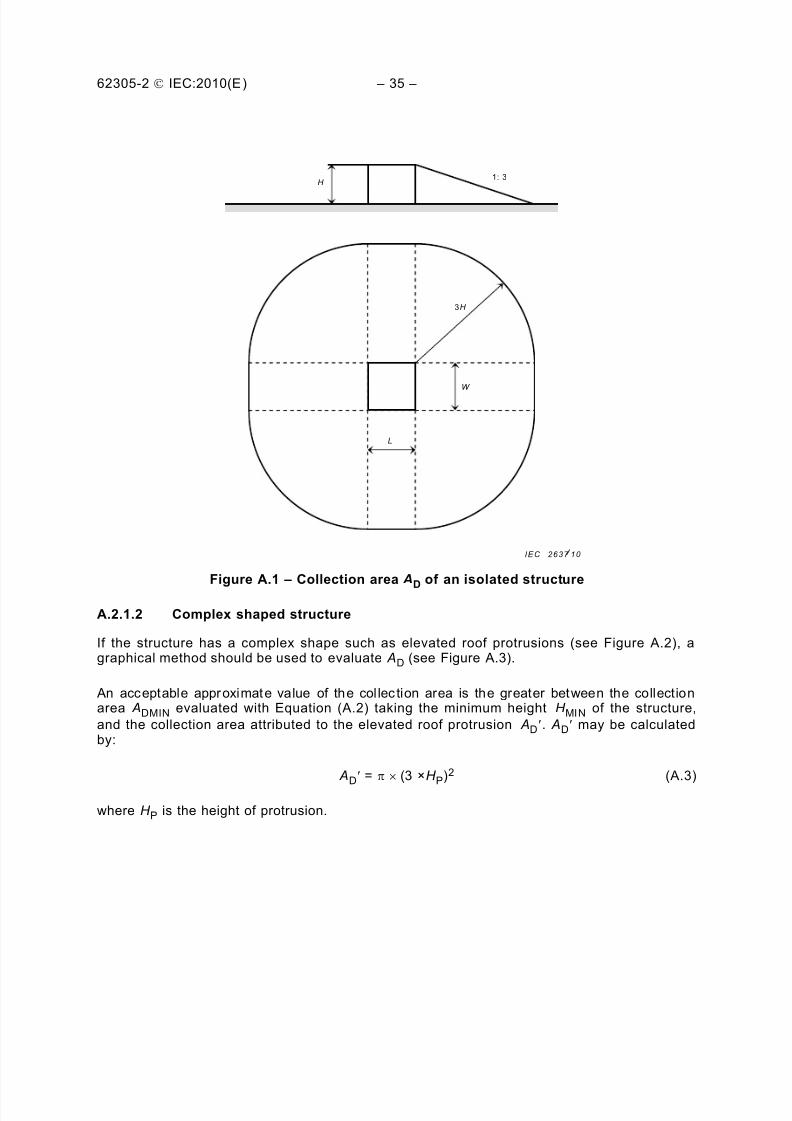
A.2.1 Determination of the collection area AD
For isolated structures on flat ground, the collection area AD is the area defined by theintersection between the ground surface and a straight line with 1/3 slope which passes fromthe upper parts of the structure (touching it there) and rotating around it. Determination of the
value of AD may be performed graphically or mathematically.
A.2.1.1 Rectangular structure
For an isolated rectangular structure with length L, width W , and height H on flat ground, thecollection area is then equal to:
AD = L ´ W + 2 ´ (3 ´ H ) ´ (L + W ) + p ´ (3 ´ H)2 (A.2)
where L, W and H are expressed in metres (see Figure A.1).
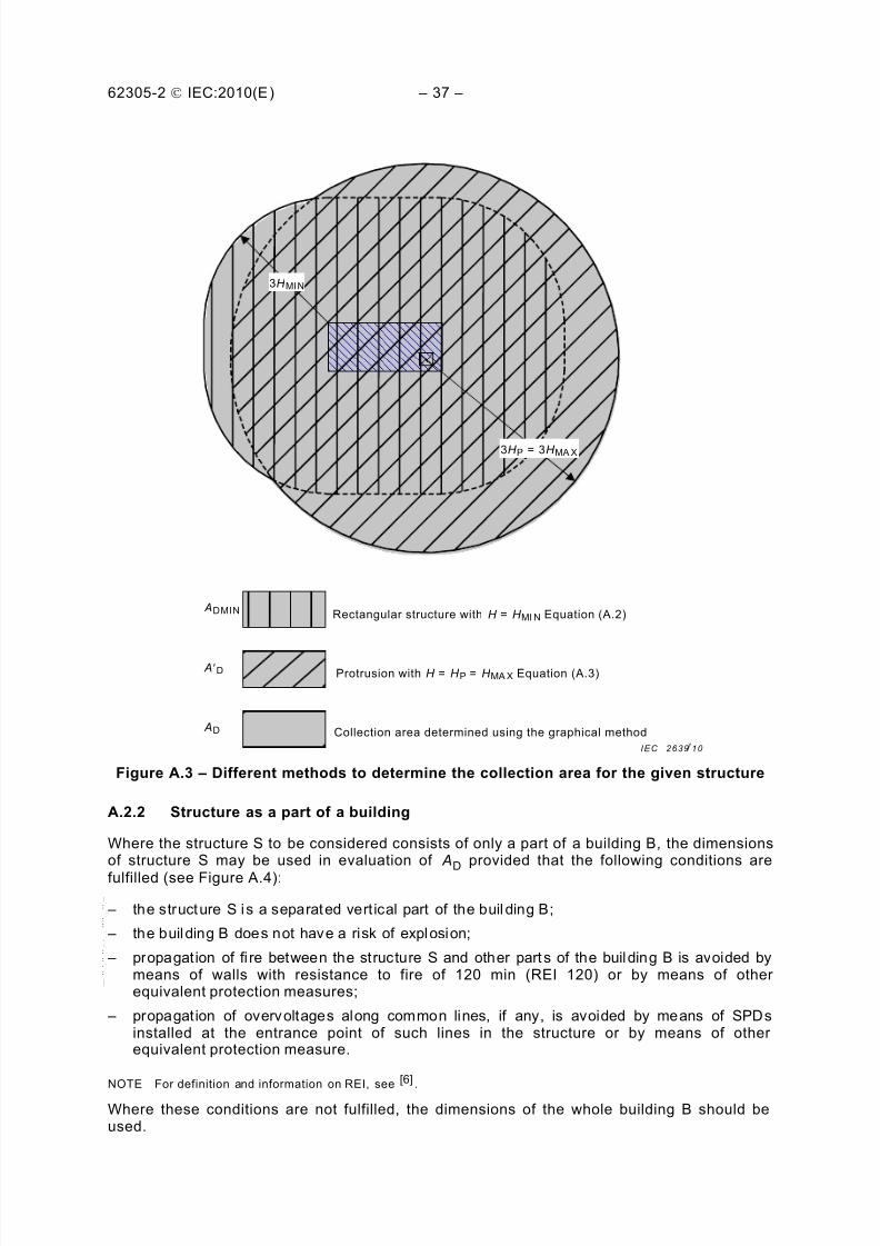
If the structure has a complex shape such as elevated roof protrusions (see Figure A.2), agraphical method should be used to evaluate AD (see Figure A.3).
An acceptable approximate value of the col lec tion area is the greater between the collectionarea ADMIN evaluated with Equation (A.2) taking the minimum height H MIN of the structure,
and the collection area attributed to the elevated roof protrusion AD¢. AD¢ may be calculatedby:
Figure A.3 – Different methods to determine the collection area for the given structure
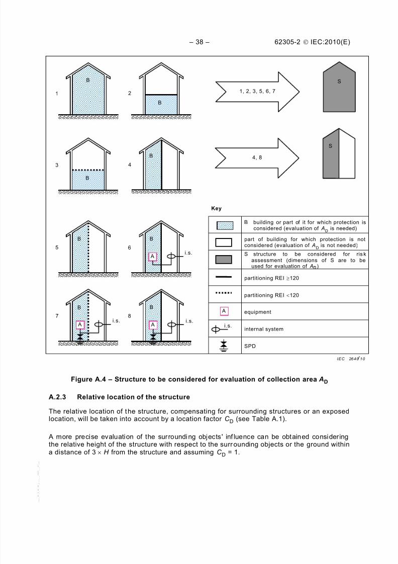
A.2.2 Structure as a part of a building
Where the structure S to be considered consists of only a part of a building B, the dimensionsof structure S may be used in evaluation of AD provided that the following conditions are
fulfilled (see Figure A.4):
– the structure S is a separated vert ical part of the buil ding B;
– the building B does not have a risk of explosion;
– propagation of fi re between the structure S and other part s of the building B is avoided bymeans of walls with resistance to fire of 120 min (REI 120) or by means of otherequivalent protection measures;
– propagation of overvoltages along common lines, if any, is avoided by means of SPDsinstalled at the entrance point of such lines in the structure or by means of otherequivalent protection measure.
NOTE For definition and information on REI, see [6] .
Where these conditions are not fulfilled, the dimensions of the whole building B should beused.
3H P = 3H MA X
3H MIN
Rectangular structure with H = H MI N Equation (A.2) ADMIN
Protrusion with H = H P = H MA X Equation (A.3)
Collection area determined using the graphical method
B building or part of it for which protection isconsidered (evaluation of A
D is needed)
part of building for which protection is notconsidered (evaluation of A
D is not needed)
S structure to be considered for ris kassessment (dimensions of S are to beused for evaluation of A )
partitioning REI ³120
partitioning REI <120
equipment
internal system
SPD
Figure A.4 – Structure to be considered for evaluation of collection area AD
A.2.3 Relative location of the structure
The relative location of the structure, compensating for surrounding structures or an exposedlocation, will be taken into account by a location factor C D (see Table A.1).
A more precise evaluation of the surrounding objects' inf luence can be obtained consideringthe relative height of the structure with respect to the surrounding objects or the ground withina distance of 3 ´ H from the structure and assuming C D = 1.
Struc ture surrounded by objects of the same height or small er 0,5
Isolated structure: no other objects in the vicinity 1
Isolated structure on a hilltop or a knoll 2
A.2.4 Number of dangerous events N D for the structure
N D may be evaluated as the product:
N D = N G ´ AD ´ C D ´ 10 –6 (A.4)
where
N G is the lightning ground flash density (1/km2 ´ year);
AD is the collection area of the structure (m2) (see Figure A.5);
C D is the location factor of the structure (see Table A.1).
A.2.5 Number of dangerous events N DJ for an adjacent structure
The average annual number of dangerous events due to flashes to a structure connected atthe far end of a line, N DJ (see 6.5 and Figure A.5) may be evaluated as the product:
N DJ = N G ´ ADJ ´ C DJ ´ C T ×10 –6 (A.5)
where
N G is the lightning ground flash density (1/km2 ´ year);
ADJ is the collection area of the adjacent structure (m2) (see Figure A.5);
C DJ is the location factor of the adjacent structure (see Table A.1);
C T is the line type factor (see Table A.3);
A.3 Assessment of the average annual number of dangerous events N M dueto flashes near a structure
N M
may be evaluated as the product:
N M = N G ´ AM ´ 10-6 (A.6)
where
N G is the lightning ground flash density (1/km2 ´ year);
AM is the collection area of flashes striking near the structure (m2).
The collection area AM extends to a line located at a distance of 500 m from the perimeter ofthe structure (see Figure A.5):
NOTE 2 The ground resistivity affects the collection area AL of buried sections. In general, the larger the groundresistivity, the larger the collection area ( AL proportional to √ρ ). The installation factor of Table A.2 is based on ρ =400 Wm.
NOTE 3 More information on the coll ection areas AI for telecommunication lines can be found in ITU-TRecommendation K.47
[7 ].
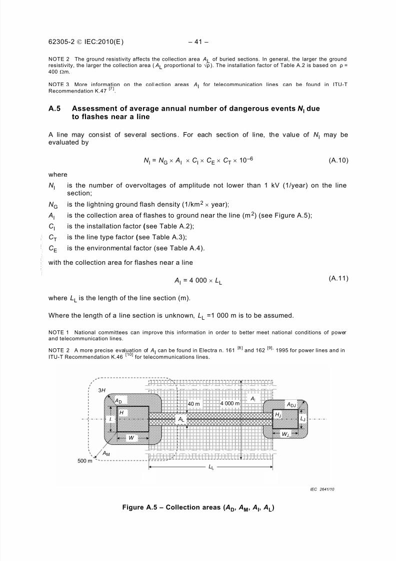
A.5 Assessment of average annual number of dangerous events N I dueto flashes near a line
A line may consist of several sections. For each section of line, the value of N I may beevaluated by
N I = N G ´ AI ´ C I ´ C E ´ C T ´ 10 –6 (A.10)
where
N I is the number of overvoltages of amplitude not lower than 1 kV (1/year) on the line
section; N G is the lightning ground flash density (1/km2 ´ year);
AI is the collection area of flashes to ground near the line (m2) (see Figure A.5);
C I is the installation factor (see Table A.2);
C T is the line type factor (see Table A.3);
C E is the environmental factor (see Table A.4).
with the collection area for flashes near a line
AI = 4 000 ´ LL(A.11)
where LL is the length of the line section (m).
Where the length of a line section is unknown, LL =1 000 m is to be assumed.
NOTE 1 National committees can improve this information in order to better meet national conditions of powerand telecommunication lines.
NOTE 2 A more precise evaluation of AI can be found in Electra n. 161[8 ]
The probabilities given in this annex are valid if protection measures conform to:
– IEC 62305-3 for protect ion measures to reduce injury to liv ing beings and forprotection measures to reduce physical damage;
– IEC 62305-4 for protection measures to reduce fai lure of internal systems.
Other values may be chosen, if justified.
Values of probabilities P X less than 1 may be selected only if the measure or characteristic isvalid for the entire structure or zone of structure (ZS) to be protected and for all relevantequipment.
B.2 Probability P A that a flash to a structure will cause injury to living beingsby electric shock
The values of probability P A of shock to living beings due to touch and step voltage by alightning flash to the structure, depend on the adopted LPS and on additional protectionmeasures provided:
P A = P TA ´ P B (B.1)
where
P TA depends on additional protection measures against touch and step voltages, such asthose listed in Table B.1. Values of P TA are given in Table B.1.
P B depends on the lightning protection level (LPL) for which the LPS conforming toIEC 62305-3 is designed. Values of P B are given in Table B.2.
Table B.1 – Values of probability P TA that a flash to a structure will cause shockto living beings due to dangerous touch and step voltages
Additional protection measure P TA
No protection measures 1
Warning notices 10 –1
Electrical insulation (e.g. at least 3 m m cross-linked polyethylene)of exposed parts (e.g. down-conductors)
10 –2
Effective soil equipotentialization 10 –2
Physical restrictions or building framework used as a down-conductor system
0
If more than one provision has been taken, the value of P TA is the product of thecorresponding values.
NOTE 1 Protection measures are effective in reducing P A
only in structures protected by an LPS or structureswith continuous metal or reinforced concrete framework acting as a natural LPS, where bonding and earthingrequirements of IEC 62305-3 are satisfied.
NOTE 2 For more information see 8.1 and 8.2 of IEC 62305-3:2010.
B.3 Probability P B that a flash to a structure will cause physical damage
An LPS is sui table as a protect ion measure to reduce P B.
The values of probability P B of physical damage by a flash to a structure, as a function oflightning protection level (LPL) are given in Table B.2.
Table B.2 – Values of probability P B depending on the protection measuresto reduce physical damage
Characteristics of structure Class of LPS P B
Structure not protected by LPS _ 1
Structure protected by LPS IV 0,2
III 0,1
II 0,05
I 0,02
Structure with an air-termination system conf orming to LPS I and a continuous metal orreinforced concrete framework acting as a natural down-conductor system
0,01
Structure with a metal roof and an air-termination s ystem, possibly including naturalcomponents, with complete protection of any roof installations against direct lightningstrikes and a continuous metal or reinforc ed concrete framework acting as a naturaldown-conductor system
0,001
NOTE 1 Values of P B other than those given in Table B.2 are possible if based on a detailed investigation taking
into account the requirements of sizi ng and interception criteria defined in IEC 62305-1.
NOTE 2 The characteristics of LPS, including those of SPD for lightning equipotential bonding, are reported inIEC 62305-3.
B.4 Probability P C that a flash to a structure will cause failure of internalsystems
A coordinated SPD system is suitable as a protection measure to reduce P C.
The probability P C that a flash to a structure will cause a failure of internal systems is given
by:
P C = P SPD ´ C LD (B.2)
P SPD depends on the coordinated SPD system conforming to IEC 62305-4 and to the lightningprotection level (LPL) for which it s SPDs are designed. Values of P SPD are given in Table B.3.
C LD is a factor depending on shielding, grounding and isolation conditions of the line to whichthe internal system is connected. Values of C LD are given in Table B.4.
Table B.3 – Value of the probability P SPD as a function of LPLfor which SPDs are designed
LPL P SP D
No coordinated SPD system 1
III-IV 0,05
II 0,02
I 0,01
NOTE 2 0,005 – 0,001
NOTE 1 A coordinated SPD system is effective in reducing P C
only in structures protected by an LPS orstructures with continuous metal or reinforced concrete framework acting as a natural LPS, where bonding andearthing requirements of IEC 62305-3 are satisfied.
NOTE 2 The values of P SPD
may be reduced for SPDs having better protection characteristics (higher nominalcurrent I N, lower protective level U P, etc.) compared with the requirements defined for LPL I at the relevantinstallation locations (see T able A.3 of IEC 62305-1:2010 for information on lightning current pr obabilities, and
Ann ex E of IEC 62305-1:2010 and Ann ex D of IEC 62305-4:2 010 for li ghtning current sharing). The s ame ann exesmay be used for SPDs having higher pr obabilities P
SP D.
Table B.4 – Values of factors C LD and C LI depending on shielding, groundingand isolation conditions
External line type Connection at entrance C LD C
LI
Aer ial line unshielded Undefined 1 1
Buried line unshielded Undefined 1 1
Multi grounded neutral power line None 1 0,2
Shielded buried line (power orTLC)
Shield not bonded to the same bonding bar as
equipment
1 0,3
Shielded aerial line (power or TLC)Shield not bonded to the same bonding bar asequipment
1 0,1
Shielded buried line(power or TLC) Shield bonded to the same bonding bar as equipment 1 0
Shielded aerial line (power or TLC) Shield bonded to the same bonding bar as equipment 1 0
Lightning protective cable or wiringin lightning protective cable ducts,metallic conduit, or metallic tub es
Shield bonded to the same bonding bar as equipment 0 0
(No external line) No connection to external lines (stand-alone systems) 0 0
Any t ype Isolating in terf ace acc ording t o IEC 623 05-4 0 0
NOTE 3 In the evaluation of probability P C
, values of C LD
in Table B.4 refer to shielded internal systems; forunshielded internal systems, C
LD = 1 should be assumed.
NOTE 4 For non-shielded internal s ystems
– not connect ed to external lines (s tand-alone s ystems) , or
– conne cted to ext ernal li nes thr ough i sol at ing inter fac es, or
– con nec ted to extern al lines cons is ting of lightning protect ive cable or systems with wir in g in lightningprotective cable ducts, metallic c onduit, or metallic tubes, bonded to the same bonding bar as equipment,
a coordinated SPD system according to IEC 62305-4 is not necessary to reduce P c, provided that the induced
voltage U I is not higher than the withstand voltage U w of the internal system (U
I ≤ U
w). For evaluation of
induced voltage U I see Annex A of IEC 62305-4:2010.
B.5 Probability P M that a flash near a structure will cause failure of internalsystems
A grid-l ike LPS, screening, routing precautions, increased withstand voltage, isolatinginterfaces and coordinated SPD systems are suitable as protection measures to reduce P
M.
The probability P M that a lightning flash near a structure will cause failure of internal systemsdepends on the adopted SPM measures.
When a coordinated SPD system meeting the requirements of IEC 62305-4 is not provided,the value of P M is equal to the value of P MS.
When a coordinated SPD system according to IEC 62305-4 is provided, the value of P M isgiven by:
P M = P SPD ´ P MS (B.3)
For internal systems with equipment not conforming to the resistibility or withstand voltagelevel given in the relevant product standards, P M = 1 should be assumed.
The values of P MS are obtained from the product:
P MS = (K S1 ´ K S2 ´ K S3 ´ K S4)2 (B.4)
where
K S1 takes into account the screening effectiveness of the structure, LPS or other shields atboundary LPZ 0/1;
K S2 takes into account the screening effectiveness of shields internal to the structure atboundary LPZ X/Y (X>0, Y>1);
K S3 takes into account the characteristics of internal wiring (see Table B.5);
K S4 takes into account the impulse withstand voltage of the system to be protected.
NOTE 1 When equipment provided with isolating interfaces consisting of isolation transformers with earthedscreen between windings, or of fibre optic cables or optical couplers is used, P
MS = 0 should be assumed.
Inside an LPZ, at a safety distance from the boundary screen at least equal to the mesh widthw m, factors K S1 and K S2 for LPS or spatial grid-like shields may be evaluated as
K S1 = 0,12 ´ w m1 (B.5)
K S2 = 0,12 ´ w m2 (B.6)
where wm1 (m) and w m2 (m) are the mesh widths of grid-like spatial shields, or of mesh typeLPS down-conductors or the spacing between the structure metal columns, or the spacingbetween a reinforced concrete framework acting as a natural LPS.
For continuous metal shields with thicknesses not lower than 0,1 mm, K S1 = K S2 = 10 –4.
NOTE 2 Where a meshed bonding network is provided according to IEC 62305-4, values of K S1
and K S2
may behalved.
Where the induction loop is running closely to the LPZ boundary screen conductors at adistance from the shield shorter than the safety distance, the values of K S1 and K S2 will behigher. For instance, the values of K S1 and K S2 should be doubled where the distance to theshield ranges from 0,1 w m to 0,2 w m.
For a cascade of LPZs the resulting K S2 is the product of the relevant K S2 of each LPZ.
NOTE 3 The maximum value of K S1 and K
S2 is limited to 1.
Table B.5 – Value of factor K S3 depending on internal wiring
Type of internal wiring K S3
Unshielded cable – no routing precaution inorder to avoid loopsa
1
Unshielded cable – routing pr ecaution in orderto avoid large loopsb
0,2
Unshielded cable – routing pr ecaution in orderto avoid loopsc
0,01
Shielded cables and cables running in metalconduitsd
0,0001
a Loop conductors with different routing in large buildings (loop area in the order of 50 m2).
b Loop conductors routed in the same conduit or loop conductors with different routing in
small buildings (l oop area in the order of 10 m2).
c Loop conductors routed in the same cable (loop area in the order of 0,5 m 2).
d Shields and the metal conduits bonded to an equipotential bonding bar at both ends andequipment is c onnected to the same bonding bar.
The factor K S4 is evaluated as:
K S4 = 1/U W (B.7)
where
U w is the rated impulse withstand voltage of system to be protected, in kV.
NOTE 4 The maximum value of K S4
is limited to 1.
If there is equipment with different impulse withstand levels in an internal system, the factorK S4 relevant to the lowest impulse withstand level should be selected.
B.6 Probability P U that a flash to a line will cause injury to living beings byelectric shock
The values of probability P U of injury to living beings inside the structure due to touch voltage
by a flash to a line entering the structure depends on the characteristics of the line shield, theimpulse withstand voltage of internal systems connected to the line, the protection measureslike physical restrictions or warning notices and the isolating interfaces or SPD(s) provided forequipotential bonding at the entrance of the line according to IEC 62305-3.
NOTE 1 A coordinated SPD system according to IEC 62305-4 is not necessary to reduce P U
; in this case SPD(s)according to IEC 62305-3 are sufficient.
The value of P U is given by:
P U = P TU ´ P EB ´ P LD ´ C LD (B.8)
where
P TU depends on protection measures against touch voltages, such as physical restrictions orwarning notices. Values of P TU are given in Table B.6;
P EB depends on lightning equipotential bonding (EB) conforming to IEC 62305-3 and on thelightning protection level (LPL) for which its SPDs are designed. Values of P EB aregiven in Table B.7;
P LD is the probability of failure of internal systems due to a flash to the connected linedepending on the line characteristics. Values of P
LD
are given in Table B.8.
C LD is a factor depending on shielding, grounding and isolation conditions of the line. Valuesof C LD are given in Table B.4.
NOTE 2 When SPD(s) according to IEC 62305-3 are provided for equipotential bonding at the entrance of theline, earthing and bonding according to IEC 62305-4 may improve pr otection.
Table B.6 – Values of probability P TU that a flash to an entering line will causeshock to living beings due to dangerous touch voltages
Protection measure P TU
No protection measures 1
Warning notices 10 –1
Electrical insulation 10 –2
Physical restrictions
0
NOTE 3 If more than one provision has been taken, the value of P TU is the product of the c orresponding values.
Table B.7 – Value of the probability P EB as a function of LPLfor which SPDs are designed
LPL P EB
No SPD 1
III-IV 0,05
II 0,02
I 0,01
NOTE 3 0,005 – 0,001
NOTE 4 The values of P EB
may be reduced for SPDs having better protection characteristics (higher nominalcurrent I N, lower protective level U P, etc.) compared with the requirements defined for LPL I at the relevantinstallation locations (see T able A.3 of IEC 62305-1:2010 for information on lightning current pr obabilities, and
Ann ex E of IEC 62305-1:2010 and Ann ex D of IEC 62305-4:2 010 for li ghtning current sharing). The s ame ann exesmay be used for SPDs having higher pr obabilities P
EB.
Table B.8 – Values of the probability P LD depending on the resistance R S of the cablescreen and the impulse withstand voltage U
W
of the equipment
Linetype
Routing, shielding and bonding conditionsWithstand voltage U
W in kV
1 1,5 2,5 4 6
Powerlines
or
Telecomlines
Aer ial or bur ied line, uns hield ed or sh iel ded whoseshield is not bonded to the same bonding bar asequipment
1 1 1 1 1
Shielded aerial or buriedwhose shield bonded to thesame bonding bar asequipment
5W/km < R S £ 20 W/km 1 1 0,95 0,9 0,8
1W/km < R S £ 5 W/km 0,9 0,8 0,6 0,3 0,1
R S £ 1 W/km 0,6 0,4 0,2 0,04 0,02
NOTE 5 In suburban/urban areas, an LV power li ne uses typically uns hielded buried cable whereas atelecommunication line uses a buried shielded cable (with a minimum of 20 conductors, a shield resistance of 5Ω/km, a copper wire di ameter of 0,6 mm). In rur al areas an LV power line uses an unshielded aerial cable whereasa telecommunication line uses an aerial unshielded cable (copper wire diameter: 1 mm). An HV buried power lineuses typically a shielded cable with a shield resistance in the order of 1 Ω/km to 5 Ω/km. National committees mayimprove this information in order to better m eet national conditions of power and telecommunication lines.
B.7 Probability P V that a flash to a line will cause physical damage
The values of probability P V of physical damage by a flash to a line entering the structuredepend on the characteristics of the line shield, the impulse withstand voltage of internalsystems connected to the line and the isolating interfaces or the SPDs provided forequipotential bonding at the entrance of the line according to IEC 62305-3.
NOTE A coordinated SPD system according to IEC 62305-4 is not necessary to reduce P V; in this case, SPDsaccording to IEC 62305-3 are sufficient.
The value of P V is given by:
P V = P EB ´ P LD ´ C LD (B.9)
where
P EB depends on lightning equipotential bonding (EB) conforming to IEC 62305-3 and on the
lightning protection level (LPL) for which its SPDs are designed. Values of P EB aregiven in Table B.7;
P LD is the probability of failure of internal systems due to a flash to the connected linedepending on the line characteristics. Values of P LD are given in Table B.8;
C LD is a factor depending on shielding, grounding and isolation conditions of the line. Valuesof C LD are given in Table B.4.
B.8 Probability P W that a flash to a line will cause failure of internal systems
The values of probability P W that a flash to a line entering the structure will cause a failure ofinternal systems depend on the characteristics of line shielding, the impulse withstand voltageof internal systems connected to the line and the isolating interfaces or the coordinated SPDsystem installed.
The value of P W is given by:
P W = P SPD ´ P LD ´ C LD (B.10)
where
P SPD depends on the coordinated SPD system conforming to IEC 62305-4 and the lightningprotection level (LPL) for which its SPDs are designed. Values of P SPD are given inTable B.3;
P LD is the probability of failure of internal systems due to a flash to the connected linedepending on the line characteristics. Values of P LD are given in Table B.8;
C LD is a factor depending on shielding, grounding and isolation conditions of the line. Valuesof C LD are given in Table B.4.
B.9 Probability P Z that a lightning flash near an incoming line will causefailure of internal systems
The values of probability P Z that a lightning flash near a line entering the structure will causea failure of internal systems depend on the characteristics of the line shield, the impulsewithstand voltage of the system connected to the line and the isolating interfaces or thecoordinated SPD system provided.
P SPD depends on the coordinated SPD system conforming to IEC 62305-4 and the lightningprotection level (LPL) for which its SPDs are designed. Values of P SPD are given inTable B.3;
P LI is the probability of failure of internal systems due to a flash near the connected linedepending on the line and equipment characteristics. Values of P LI are given inTable B.9;
C LI is a factor depending on shielding, grounding and isolation conditions of the line. Valuesof C LI are given in Table B.4.
Table B.9 – Values of the probability P LI depending on the line typeand the impulse withstand voltage U W of the equipment
Linetype
Withstand voltage U W
in kV
1 1,5 2,5 4 6
Powerlines 1 0,6 0,3 0,16 0,1
TLClines
1 0,5 0,2 0,08 0,04
NOTE More precise evaluation of P LI
can be found in IEC/TR 62066:2002 for power lines[11]
The values of amount of loss LX should be evaluated and fixed by the lightning protectiondesigner (or the owner of the structure). The typical mean values of loss LX in a structuregiven in this annex are merely values proposed by the IEC. Different values may be assignedby each national committee or after detailed investigation.
NOTE 1 When the damage to a structure due to li ghtning may also involve surr ounding structures or theenvironment (e.g. chemical or radioactive emissions), a more detailed evaluation of L
X that takes into account thisadditional loss should be p erformed.
NOTE 2 It is recommended that the equations given in this annex be used as the primary source of values for LX.
C.2 Mean relative amount of loss per dangerous event
The loss LX refers to the mean relative amount of a particular type of damage for onedangerous event caused by a lightning flash, considering both its extent and effects.
The loss value LX varies with the type of loss considered:
– L1 (Loss of human life, including permanent injury): the endangered number ofpersons (victims);
– L2 (Loss of publ ic serv ice): the number of users not served;
– L3 (Loss of cultural her itage): the endangered economic value of structure andcontent;
– L4 (Loss of economic values): the endangered economic value of animals, thestructure (including its activities), content and internal systems,
and, for each type of loss, with the type of damage (D1, D2 and D3) causing the loss.
The loss LX should be determined for each zone of the structure into which it is divided.
C.3 Loss of human life (L1)
The loss value LX for each zone can be determined according to Table C.1, considering that:
– loss of human life is affected by the characteristics of the zone. These are taken intoaccount by increasing (hz) and decreasing (r t, r p, r f ) factors;
– the maximum value of loss in the zone shal l be reduced by the rat io between the numberof persons in the zone (nz) versus the total number of persons (nt) in the whole structure;
– the t ime in hours per year for which the persons are present in the zone (t z), if it is lowerthan the total 8 760 h of a year, will also reduce the loss.
Table C.1 – Type of loss L1: Loss values for each zone
Type ofdamage
Typical loss Equation
D1
L A
= r t ´ L
T ´ n
Z
/ nt ´ t
z
/ 8 760 (C.1)
D1 LU = r
t ´ LT ´ nZ / n
t ´ t z/8 760 (C.2)
D2 LB = L
V = r p ´ r f ´ h
z ´LF ´ nZ
/ nt ´ t z / 8 760 (C.3)
D3 LC = L
M = LW = L
Z = LO ´ nZ
/ nt ´ t z / 8 760 (C.4)
where
LT is the typical mean relative numbers of victims injured by electric shock (D1) due to onedangerous event (see Table C.2);
LF is the typical mean relative numbers of victims by physical damage (D2) due to onedangerous event (see Table C.2);
LO is the typical mean relative numbers of victims by failure of internal systems (D3) due toone dangerous event (see Table C.2);
r t is a factor reducing the loss of human life depending on the type of soil or floor (seeTable C.3);
r p is a factor reducing the loss due to physical damage depending on the provisions takento reduce the consequences of fire (see Table C.4);
r f is a factor reducing the loss due to physical damage depending on the risk of fire or onthe risk of explosion of the structure (see Table C.5);
hz is a factor increasing the loss due to physical damage when a special hazard is present(see Table C.6);
nz is the number of persons in the zone;nt is the total number of persons in the structure;
t z is the time in hours per year for which the persons are present in the zone.
Table C.2 – Type of loss L1: Typical mean values of LT, LF and LO
Type of damage Typical loss value Type of structure
D1injuries
LT 10 –2 All types
D2physical damage LF
10 –1 Risk of explosi on
10 –1 Hospital, hotel, school, civic building
5´10 –2 Public entertainment, church, museum
2´10 –2 Industrial, commercial
10 –2 Others
D3failure of internal
systemsL
O
10 –1 Risk of explosi on
10 –2 Intensi ve care unit and operation block of hospit al
10 –3 Other parts of hospit al
NOTE 1 Values of Table C.2 refer to a continuous attendance of people in the structure.
NOTE 2 In case of a struc ture with risk of explosion, the values for LF and LO may need a more detailedevaluation, considering the type of structure, the risk explosion, the zone concept of hazardous areas and the
measures to meet the risk.
When the damage to a structure due to lightning involves surrounding structures or theenvironment (e.g. chemical or radioactive emissions), additional loss (LE) should be taken intoaccount to evaluate the total loss (LFT):
LFE being the loss due to physical damage outside the structure;
t e being the time of presence of people in the dangerous place outside the structure.
NOTE 3 If values of LFE and t
e are unknown, L
FE ´ t
e/8 760 = 1 should be ass umed.
Table C.3 – Reduction factor r t as a function of the type of surface of soil or floor
Type of surfaceb Contact resistancek Wa
r t
Agr icultur al, concr ete £ 1 10 –2
Marble, ceramic 1 – 10 10 –3
Gravel, moquette, carpets 10 – 100 10 –4
Asphalt , l in ole um, wood ³ 100 10 –5
a Values measured between a 400 cm2 electrode compressed with a uniform force of 500 N and a point of infinity.
b A layer of insulating material, e.g. asphalt, of 5 cm thickness (or a layer of gravel 15 cm thick) generally reducesthe hazard to a tolerable level.
Table C.4 – Reduction factor r p as a function of provisions takento reduce the consequences of fire
Provisions r p
No provisions 1One of the following provisions: extinguishers; fi xed manually operated extinguishing installations;manual alarm installations; h ydrants; fire compartments; esc ape routes
0,5
One of the following provisions: fixed automatically operated extinguishing installations; automaticalarm installations
a
0,2
aOnly if protected against overvoltages and other damages and if f iremen can arrive in less than 10 min.
If more than one provision has been taken, the value of r p should be taken as the lowest ofthe relevant values.
In structures with risk of explosion, r p = 1 for all cases.
Table C.5 – Reduction factor r f as a function of risk of fire or explosion of structure
Risk Amount of risk r f
Explosion
Zones 0, 20 and solid
explosive
1
Zones 1, 21 10 –1
Zones 2, 22 10 –3
Fire
High 10 –1
Ordinary 10 –2
Low 10 –3
Explosion or fire None 0
NOTE 4 In case of a structure with risk of explosion, the value for r f may need a more detailed evaluation.
NOTE 5 Structures with a high risk of fire may be assumed to be structures made of combustible materials or
structures with roofs made of combustible materi als or structures with a specifi c fire load larger than 800 MJ/m 2.
NOTE 6 Structures with an ordinary risk of fire may be assumed to be structures with a specific fire load between800 MJ/m2 and 400 MJ/m2.
NOTE 7 Structures with a low risk of fire may be assumed to be structures with a specific fire load less than 400MJ/m2, or structures containing only a sm all amount of combustible material.
NOTE 8 Specific fire load is the ratio of the energy of the total amount of the combustible material in a structureand the overall surface of the structure.
NOTE 9 For the purposes of this part of IEC 62305, structures containing hazardous zones or containing solidexplosive materials should not be assumed to be structures with a risk of explosion if any one of the followingconditions is fulfilled:
a) the time of presence of explosive substances is lower than 0,1 h/year;
b) the volume of explosive atmosphere is negligible according to IEC 60079-10-1[2 ]
and IEC 60079-10-2[3 ]
;
c) the zone cannot be hit directly by a flash and dangerous sparking in the zone is avoided.
NOTE 10 For hazardous zones enclosed within metallic shelters, condition c) is fulfilled when the shelter, as anatural air-termination system, acts safely without puncture or hot-spot problems, and internal systems inside theshelter, if any, are protected against overvoltages to avoid dangerous sparking.
Table C.6 – Factor hz increasing the relative amount of lossin presence of a special hazard
Kind of special hazard hz
No special hazard 1
Low level of panic (e.g. a structure limit ed to two floors and the number of persons not greaterthan 100)
2
Average level of panic (e. g. st ructures des igned for cu ltura l or sport event s with a number ofparticipants between 100 and 1 000 persons)
5
Difficulty of evacuation (e.g. structures with immobile persons, hospitals) 5
High level of panic (e.g. structures designed for cultur al or sport events with a number ofparticipants – greater than 1 000 persons)
10
C.4 Unacceptable loss of service to the public (L2)
The loss value LX for each zone can be determined according to Table C.7, considering that:
– loss of publ ic service is affected by the characteristics of the zone of the structure. Theseare taken into account by decreasing (r f , r p) factors;
– the maximum value of loss due to the damage in the zone must be reduced by the rat iobetween the number of users served by the zone (nz) versus the total number of users (nt)served by the whole structure.
Table C.7 – Type of loss L2: Loss values for each zone
Type of damage Typical loss Equation
D2 LB = L
V = r p ´ r f ´ L
F ´ n
z/n
t (C.7)
D3 LC = L
M = LW = L
Z = LO
´ nz/n
t (C.8)
where
LF is the typical mean relative number of users not served, resulting from physical damage(D2) due to one dangerous event (see Table C.8);
LO is the typical mean relative numbers of users not served resulting from failure of internalsystems (D3) due to one dangerous event (see Table C.8);
r p is a factor reducing the loss due to physical damage depending on the provisions taken
to reduce the consequences of fire (see Table C.4);
r f is a factor reducing the loss due to physical damage depending on the risk of fire(see Table C.5);
nz is the number of users served by the zone;
nt is the total number of users served by the structure.
Table C.8 – Type of loss L2: Typical mean values of LF and LO
Type of damage Typical loss value Type of service
D2physical damage
LF
10 –1 Gas, water, power supply
10 –2 TV, telecommunications lines
D3failure of internal
systemsL
O
10 –2 Gas, water, power supply
10 –3 TV, telecommunications lines
C.5 Loss of irreplaceable cultural heritage (L3)
The loss value LX for each zone can be determined according to Table C.9, considering that:
– loss of cultural her itage is affected by the characteristics of the zone. These are takeninto account by decreasing (r f , r p) factors;
– the maximum value of loss due to the damage of the zone must be reduced by the
ratio between the value of the zone (c z) versus the total value (c t) of the wholestructure (building and content).
Table C.9 – Type of loss L3: Loss values for each zone
Type of damage Typical loss value Equation
D2physical damage
LB = L
V = r p ´ r
f ´ L
F ´ c
z / c
t (C.9)
where
LF is the typical mean relative value of all goods damaged by physical damage (D2) due toone dangerous event (see Table C.10);
r p is a factor reducing the loss due to physical damage depending on the provisions taken toreduce the consequences of fire (see Table C.4);
r f is a factor reducing the loss due to physical damage depending on the risk of fire(see Table C.5);
c z is the value of cultural heritage in the zone;
c t is the total value of building and content of the structure (sum over all zones).
Table C.10 – Type of loss L3: Typical mean value of LF
Type of damage Typical loss value Type of structure or zone
D2physical damage
LF 10 –1 Museums, galleries
C.6 Economic loss (L4)
The loss value LX for each zone can be determined according to Table C.11, considering that:
– loss of economic values is affected by the character istics of the zone. These are taken intoaccount by decreasing (r t, r p, r f ) factors;
– the maximum value of loss due to the damage of the zone must be reduced by the rat iobetween the relevant value in the zone versus the total value (c t) of the whole structure(animals, building, content and internal systems including their activities). The relevantvalue of the zone depends on the type of damage:
D1 (injuries of animals due to shock): c a (value of animals only)
D2 (physical damage): c a + c b + c c + c s (value of all goods)
D3 (failures of internal systems): c s (value of internal systems and their activities only)
Table C.11 – Type of loss L4: Loss values for each zone
Type of damage Typical loss Equation
D1 L A = r t × LT × c a / c ta (C.10)
D1 LU = r t × LT × c a / c ta (C.11)
D2 LB = LV = r p × r f × LF × (c a + c b + c c + c s) / c ta (C.12)
D3 LC = LM = LW = LZ = LO × c s / c ta (C.13)
aThe ratios c a / c t and (c a + c b + c c + c s) / c t and c s / c t have only to be considered in the eq.
(C.10) – (C.13), if the risk assessment is conducted in accordance with clause 6.10, using Annex D. In cas e of us ing a representati ve value for the tol erable risk R4 in acc ord anc e wit hTable 4, the ratios do not have to be taken into account. In these cases, the ratios have to bereplaced by the value 1.
where
LT is the typical mean relative value of all goods damaged by electric shock (D1) due toone dangerous event (see Table C.12);
LF is the typical mean relative value of all goods damaged by physical damage (D2) due toone dangerous event (see Table C.12);
LO is the typical mean relative value of all goods damaged by failure of internal systems(D3) due to one dangerous event (see Table C.12);
r t is a factor reducing the loss of animals depending on the type of soil or floor (seeTable C.3);
r p is a factor reducing the loss due to physical damage depending on the provisions takento reduce the consequences of fire (see Table C.4);
r f is a factor reducing the loss due to physical damage depending on the risk of fire or onthe risk of explosion of the structure(see Table C.5);
NOTE 1 In structures where there is a risk of explosion, the values for LF and L
O may need more detailed
evaluation, where consideration of the type of structure, the risk explosion, the zone concept of hazardous areasand the measures to meet the risk, etc. are addressed.
When the damage to a structure due to lightning involves surrounding structures or theenvironment (e.g. chemical or radioactive emissions), additional loss (LE) should be taken intoaccount to evaluate the total loss ( LFT):
LFT = LF + LE (C.14)
where
LE = LFE ´ c e / c t (C.15)
LFE is the loss due to physical damage outside the structure;
c e is the total value of goods in dangerous place outside the structure.NOTE 2 If the value of L
In Annex E case studies relevant to a country house, an office building, a hospital and anapartment block are developed with the aim of showing
– how to cal culate the r isk and determine the need for protection,
– the contribution of dif ferent r isk components to the overall risk,
– the effect of dif ferent protection measures to mitigate the risk,
– the method of select ion from among different protection solutions taking into account thecost-effectiveness.
NOTE This annex presents hypothetical data for all cases. It is intended to provide information about riskevaluation in order to illustrate the principles contained in this part of IEC 62305. It is not intended to address theunique aspects of the conditions that exist in all faciliti es or systems.
E.2 Country house
As a f irst case study a count ry house (Figure E.1) is considered.
Loss of human life (L1) and economic loss (L4) are relevant for this type of structure.
It is required to evaluate the need for protection. This implies the need to determine only therisk R 1 for loss of human life (L1) with the risk components R A, R B, R U and R V (according toTable 2) and to compare it with the tolerable risk R T = 10-5 (according to Table 4). Suitableprotection measures to mitigate such risk will be selected.
Following the decision taken by the owner that an economic evaluation is not required, therisk R 4 for economic loss (L4) is not considered.
H = 6 m
LL = 1 000 m
Telecom line (aerial)
Power line (buried)
W = 20 m
1:3 Z1 Z1 Z2
LL = 1 000 m
IEC 2642/10
Key
Z1: outside
Z2: rooms block
Figure E.1 – Country house
E.2.1 Relevant data and characteristics
The country house is located in fl at territory without any neighbouring structures. The lightningflash density is N G = 4 flashes per km2 per year. Five persons live in the house. This is alsothe total number of persons to be considered, because it is assumed that there is no personoutside the house during thunderstorm.
Table E.7 – Country house: Risk R 1 for the unprotected structure (values ´ 10 –5)
Symbol Z1 Z
2 Structure
D1Injury
R A – ≈ 0 ≈ 0
R U = R U/P + R U/T 0,002 0,002
D2Physicaldamage
R B 0,103 0,103
R V = R
V/P + R V/T
2,40 2,40
Total – 2,51 R 1 = 2,51
Tolerable R 1> R
T : Lightning protection is required R
T = 1
Because R 1 = 2,51×10 –5 is higher than the tolerable value R T = 10 –5, lightning protection forthe structure is required.
E.2.5 Risk R 1 – Selection of protection measures
According to Table E.7 the main contributions to the value of risk are given by:
– component R V (lightning flash to lines) of 96 %;
– component R B (lightning flash to structure) of 4 %.
To reduce the risk R 1 to a tolerable value, the protective measures influencing thecomponents R V and R B should be considered. Suitable measures include:
a) installing SPDs of LPL IV at the line entrance (lightning equipotential bonding) to protectboth power and telephone lines in the house. According to Table B.7 this reduces thevalue of P EB (due to SPDs on connected lines) from 1 to 0,05 and the values of P U andP V by the same factor;
b) installing an LPS of class IV (including mandatory lightning equipotential bonding). According to Tables B.2 and B.7 this reduces the value of P B from 1 to 0,2 and the valueof P EB (due to SPDs on connected lines) from 1 to 0,05 and finally the values of P U andP V by the same factor.
Inserting these values into the equations, new values of risk components are obtained, asshown in Table E.8.
Table E.8 – Country house: Risk components relevant to risk R 1 for protected structure
Type ofdamage
Symbol Result case a)´ (10 –5)
Result case b)´ (10 –5 )
D1Injury due to
shock
R A
≈ 0 ≈ 0
R U
= R U/P
+ R U/T
≈ 0 ≈ 0
D2
Physicaldamage
R B 0,103 0,021
R V 0,120 0,120
Total R 1 0,223 0,141
The choice of solution is decided on economic and technical factors.
E.3 Office building
As a second case study, an off ice bui lding with an archive, off ices and a computer centre isconsidered (Figure E.2).
Loss of human life (L1) and economic loss (L4) are relevant for this type of structure.--`,,```,,,,````-`-`,,`,,`,`,,`---
It is required to evaluate the need for protection. This implies the determination of only therisk R 1 for loss of human life (L1) with the risk components R A, R B, R U and R V (according toTable 2) and to compare it with the tolerable risk R T = 10 –5 (according to Table 4). Suitableprotection measures will be selected to reduce the risk to or below the tolerable risk.
Following the decision taken by the owner an economic evaluation is not requested; thereforethe risk R 4 for economic loss (L4) is not considered.
H = 25 m
LL
= 200 m W = 40 m
Z2 Z1
Power line (aerial)
Z3
Telecom line (buried)
Z4 Z5
LL
= 1 000 m
IEC 2643/10
Key
Z1: entrance (outside)
Z2: garden (inside)
Z3: archive
Z4: offices
Z5: computer centre
Figure E.2 – Office building
E.3.1 Relevant data and characteristics
The office building is l ocated in flat territory without any neighbouring structures. The lightningflash density is N G = 4 flashes per km2 per year.
Data for the building and its surroundings are given in Table E.9.
Data for the incoming lines and their connected internal systems are given for the power linein Table E.10 and for the telecom line in Table E.11.
Table E.9 – Office building: Environment and structure characteristics
Input parameter Comment Symbol Value Reference
Ground flash density (1/km2/year) N G
4,0
Structure dimensions (m) L, W , H 20, 40, 25
Location factor of structure Isolated structure C D
– the structure is div ided into two separate fi reproof compartments: the fi rst is the archive(Z3) and the second is the offices together with the computer centre (Z4 and Z5);
– in all inner zones, Z3, Z4 and Z5, internal systems connected to power as well as totelecom lines exist;
– no spat ial shields exi st.
In the different zones inside and outside the office building a total number of 200 personsshall be considered.
The number of persons related to each zone is different. The distribution into the individualzones is shown in Table E.12. These values are used later to subdivide the total loss valuesinto fractions for each zone.
Table E.12 – Office building: Distribution of persons into zones
ZoneNumber of
personsTime of
presence
Z1 (entrance outside) 4 8 760
Z2 (garden outsid e) 2 8 760
Z3 (archive) 20 8 760
Z4 (offices) 160 8 760
Z5 (computer centre) 14 8 760
Total nt = 200 –
Following the evaluation by the lightning protection designer, the typical mean values ofrelative amount of loss per year relevant to risk R 1 (see Table C.1) for the whole structure are
– LT = 10-2 (outside the structure), – LT = 10-2 (inside the structure),
– LF = 0,02 classified as “commercial building”.
These global values were reduced for each zone according to the number of peopleendangered in the individual zone related to the total number of people considered.
The resulting characteristics of the zones Z1 to Z5 are given in the Tables E.13 to E.17.
Table E.13 – Office building: Factors valid for zone Z1 (entrance area outside)
Table E.19 – Office building: Expected annual number of dangerous events
Symbol Result1/year
ReferenceEquation
Equation
Structure
N D
1,10 ´ 10 –1 (A.4) N D = N
G ´ A
D ´ C
D´10 –6
N M
– (A.6) Not re levant
Powerline
N L/P 3,20 ´ 10 –2 (A.8) N
L/P = N G ´ A
L/P ´ C
I/P ´ C
E/P ´ C
T/P ´ 10 –6
N I/P
3,20 (A.10) Not relevant
N DA/P
0 (A.5) No adjacent structure
Telecomline
N L/ T
8,00 ´ 10 –2 (A.8) N L/ T
= N G
´ AL/ T
´ C I/T
´ C E/T
C T/T
´ 10 –6
N I/T
8,00 (A.10) Not relevant
N DA/T
0 (A.5) No adjacent structure
E.3.4 Risk R 1 – Decision on need for protection
Values of the risk components for the unprotected structure are reported in Table E.20.
Table E.20 – Office building: Risk R 1 for the unprotected structure (values ´ 10 –5)
Type ofdamage
Symbol Z1 Z
2 Z
3 Z
4 Z
5 Structure
D1Injury dueto shock
R A 0,002 0 ≈ 0 0,001 ≈ 0 0,003
R U = R
U/P + R U/T
≈ 0 0,001 ≈ 0 0,001
D2Physicaldamage
R B 4,395 0,352 0,031 4,778
R V = R
V/P + R V/T
4,480 0,358 0,031 4,870
Total 0,002 0 8,876 0,712 0,062 R 1 = 9,65
Tolerable R 1> R
T: Lightning protection is required R
T = 1
Because R 1 = 9,65 ´ 10 –5 is higher than the tolerable value R T = 10 –5, lightning protection forthe structure is required.
E.3.5 Risk R 1 – Selection of protection measures
The risk R 1 in the structure is mainly concentrated in zone Z3 due to physical damagescaused by lightning striking the structure or the connected lines (components R B ≈ 49 % andR V ≈ 50 % together cover 99 % of the total risk) (see Table E.20).
These dominant risk components can be reduced by:
– providing the whole building with an LPS conforming to IEC 62305-3 reducing componentR B via probability P B. Lightning equipotential bonding at the entrance – a mandatoryrequirement of the LPS - reduces also the components R U and R V via probability P EB;
– providing zone Z3 (archive) with protection measures against the consequences of fire(such as extinguishers, automatic fire detection system etc.). This will reduce thecomponents R B and R V via the reduction factor r p;
– providing lightning equipotential bonding conformi ng to IEC 62305-3 at the entrance ofthe building. This will reduce only the components R U and R V via probability P EB.
Combining different elements of these protective measures the following solutions could be
adopted:
Solution a)
– Protect the building with a Class II I LPS conforming to IEC 62305-3, to reducecomponent R B (P B = 0,1).
– This LPS includes the mandatory lightning equipotential bonding at the entrance withSPDs designed for LPL III (P EB = 0,05) and reduces components R U and R V.
Solution b)
– Protect the building with a Class IV LPS conforming to IEC 62305-3, to reduce
component R B (P B = 0,2). – This LPS includes the mandatory lightning equipotential bonding at the entrance with
SPDs designed for LPL IV (P EB = 0,05) and reduces components R U and R V.
– Use fi re extinguishing (or detection) systems to reduce components R B and R V. Installa manual system in the zone Z3 (archive) (r p = 0,5).
For both solutions, the risk v alues from Table E.20 will change to the reduced values reportedin Table E.21.
Table E.21 – Office building: Risk R 1 for the protected structure (values ´ 10 –5)
Z1 Z
2 Z
3 Z
4 Z
5 Total Tolerable Result
Solution a) ≈ 0 0 0,664 0,053 0,005 R 1 = 0,722 R
T = 1 R 1 £ R
T
Solution b) ≈ 0 0 0,552 0,089 0 ,008 R 1 = 0,648 R
T = 1 R 1 £ R
T
Both solutions reduce the risk below the tolerable value. The solution to be adopted is subjectto both the best technical criteria and the most cost-effective solution.
E.4 Hospital
As a more complex case, this study considers a standard hospital facil ity with a rooms block,an operating block and an intensive care unit.
Loss of human life (L1) and economic loss (L4) are relevant for this type of facility. It isnecessary to evaluate the need for protection and the cost effectiveness of protectionmeasures; these require the evaluation of risks R 1 and R 4.
The hospital is located in flat territory without any neighbouring structures. The lightning flashdensity is N G = 4 flashes per km2 per year.
Data for the building and its surroundings are given in Table E.22.
Data for the incoming lines and their internal systems connected thereto are given for thepower line in Table E.23 and for the telecom line in Table E.24.
Table E.22 – Hospital: Environment and global structure characteristics
Input parameter Comment Symbol Value Reference
Ground flash density (1/km2/year) N G
4,0
Structure dimensions (m) L, W , H 50, 150, 10
Location factor of structure Isolated structure C D
1 Table A.1
LPS None P B 1 Table B.2
Equipotential bonding None P EB
1 Table B.7
External spatial shield None K S1
1 Equation (B.5)
Table E.23 – Hospital: Power line
Input parameter Comment Symbol Value Reference
Length (m) LL 500
Installation factor Buried C I 0,5 Table A.2
Line type factor HV power (with HV/LV
transformer)
C T 0,2 Table A.3
Environmental factor Suburban C E 0,5 Table A.4
Shield of line (W/km)Line shield bonded to the samebonding bar as equipment
R S R
S £ 1 Table B.8
Shielding, grounding, isolationLine shield bonded to the samebonding bar as equipment
C LD
1Table B.4
C LI
0
Adjac ent st ructure (m) Non e LJ, W
J, H
J –
Location factor of adjacentstructure
None C DJ
– Table A .1
Withstand voltage of internalsystem (kV)
U W
2,5
Resulting parameters
K S4 0,4 Equation (B.7)
P LD
0,2 Table B.8
P LI
0,3 Table B.9
Table E.24 – Hospital: Telecom line
Input parameter Comment Symbol Value Reference
Length (m) LL 300
Installation factor Buried C I 0,5 Table A.2
Line type factor Telecom line C T 1 Table A.3
Environmental factor Suburban C E 0,5 Table A.4
Shield of line (W/km)Line shield bonded to the samebonding bar as equipment.
R S 1< R
S £5 Table B.8
Shielding, grounding, isolation Line shield bonded to the same C LD
Adjac ent st ructure (m) Length , wid th, height LJ, W
J, H
J 20, 30, 5
Location factor of adjacent
structure
Isolated structure C DJ
1 Table A.1
Withstand voltage of internalsystem (kV)
U W
1,5
Resulting parameters
K S4
0,67 Equation (B.7)
P LD
0,8 Table B.8
P LI
0,5 Table B.9
E.4.2 Definition of zones in the hospital
The following zones are defined:
Z1 (outside building);Z2 (rooms block);
Z3 (operating block);
Z4 (intensive care unit);
taking into account the following:
– the type of surface is dif ferent outside the structure from that inside the structure;
– two separate fi re proof compartments exist: the fi rst is the rooms block (Z2) and thesecond is the operating block together with the intensive care unit (Z3 and Z4);
– in all inner zones Z2, Z3 and Z4, internal systems connected to power as well as to
telecom lines exist; – no spat ial shields exi st;
– the i ntensive care unit contains extensive sensitive electroni c systems and a spat ial shieldmay be adopted as protection measure;
In the different zones inside and outside the hospital a total number of 1 000 persons shall beconsidered.
The number of persons, the times of presence and the economic values related to each zoneare different. The distribution into the individual zones and the total values are shown inTable E.25. These values are used later to subdivide the total loss values into fractions foreach zone.
Table E.25 – Hospital: Distribution of persons and of economic values into zones
For risk R 1, following the evaluation by the lightning protection designer, the basic loss values(typical mean values of relative amount of loss per year) according to Table C.2 and theincreasing factor for special hazards according to Table C.6 are as follows:
– LT = 10-2 in zone Z1 outside the structure;
– LT = 10-2 in zones Z2, Z3, Z4 inside the structure;
– LF = 10-1 in zones Z2, Z3, Z4 inside the structure;
– hz = 5 in zones Z2, Z3, Z4 inside the structure due to difficulty of evacuation;
– LO = 10-3 in zone Z2 (rooms block);
– LO = 10-2 in zone Z3 (operating block) and zone Z4 (intensive care unit).
These basic loss values were reduced for each zone according to the Equations (C.1) to (C.4)taking into account the number of people endangered in the individual zone related to thetotal number of people considered and the time when people are present.
For risk R 4 the basic loss values according to Table C.12 are as follows:
– LT = 0 no animals endangered;
– LF = 0,5 in zones Z2, Z3, Z4 inside the structure;
– LO = 10-2 in zones Z2, Z3, Z4 inside the structure.
These basic loss values were reduced for each zone according to Equations (C.11) to (C.13)taking into account the value endangered in the individual zone related to the total value ofthe structure (animals, building, content, internal systems and activities) considered. Thevalue endangered in an individual zone depends on the type of damage:
– D1 (injury by electric shock): value c a of animals only;
– D2 (physical damage): sum of all values c a + c b + c c + c s;
– D3 (failure of internal system): value c s of internal systems and their activities only.
The resulting characteristics of the zones Z1 to Z4 are given in Tables E.26 to E.29.
Table E.26 – Hospital: Factors valid for zone Z1 (outside the building)
Input parameter Comment Symbol Value Reference
Ground surface Concrete r t 10 –2
Table C.3
Protection against shock None P TA
1
Table B.1
Risk of fire None r f 0 Table C.5
Fire protection None r p 1 Table C.4
Internal spatial shield None K S2
1 Equation (B.6)
L1: Loss of human life
Special hazard: None hz 1 Table C.5
D1: due to touch and step voltage LT 10 –2
Table C.2D2: due to physical damage LF 0
D3: due to failure of internal systems LO
0
Factor for persons in zone nz / n
t ´ t
z / 8 760 = 10 /1 000 ´ 8 760 / 8 760 – 0,0 1
Table E.27 – Hospital: Factors valid for zone Z2 (rooms block)
Because R 1 = 69,96 ´ 10 –5 is higher than the tolerable value R T = 10 –5, lightning protectionfor the structure is required.
E.4.5 Risk R 1 – Selection of protection measures
The risk R 1 is mainly influenced (see Table E.33):
– by physical damage in the zone Z2 (components R B ≈ 61 % and R V ≈ 13 % of the totalrisk);
– by failures of internal systems in the zones Z2 and Z3 (components R C ≈ 12 % respectively R C ≈ 5 %) of the total risk.
These dominant risk components can be reduced by:
– providing the whole buil ding with an LPS conforming to IEC 62305-3 reducing componentR B via probability P B. The mandatory-included lightning equipotential bonding at theentrance reduces also the components R U and R V via probability P EB;
– providing zone Z2 with protection measures against the consequences of fire (such asextinguishers, automatic fire detection system, etc.). This will reduce the components R B and R V via the reduction factor r p;
– providing zones Z3 and Z
4 with a coordinated SPD protection conforming to IEC 62305-4
for the internal power and telecom systems. This will reduce the components R C, R M, R W via the probability P SPD.
– providing zones Z3 and Z4 with an adequate spatial grid-like shield conforming toIEC 62305-4. This will reduce the component R M via the probability P M.
Combining different elements of these protective measures the following solutions could beadopted:
Solution a)
– protect the building with a Class I LPS (P B = 0,02 including also P EB = 0,01);
– instal l coordinated SPD protection on internal power and telecom systems for (1,5 x) better
than LPL I (P SPD = 0,005) in zones Z2, Z3, Z4; – provide zone Z2 with an automatic fire protection system (r p = 0,2 for zone Z2 only);
– provide zone Z3 and Z4 with a meshed shield with w m = 0,5 m.
Using this solution, the risk values from Table E.33 will change to the reduced values reportedin Table E.34.
Using this solution, the risk values from Table E.33 will change to the reduced values reportedin Table E.36.
Table E.36 – Hospital: Risk R 1 for the protected structure according to solution c)(values ´ 10-5)
Type ofdamage
Symbol Z1 Z
2 Z
3 Z
4 Structure
D1Injury dueto shock
R A » 0 » 0 » 0 » 0 » 0
R U = R
U/P + R U/T
» 0 » 0 » 0 » 0
D2Physicaldamage
R B 0,170 0,003 » 0 0,173
R V = R
V/P + R V/T
0,018 » 0 » 0 0,018
D3Failure ofinternal
systems
R C 0,034 0,012 0,002 0,048
R M
» 0 » 0 » 0 » 0
R W
= R W/ P
+ R W/ T
0,004 0,001 » 0 0,005
R Z = R
Z/P + R Z/T
Total » 0 0,226 0,016 0,002 R 1 = 0,244
Tolerable R 1
R T: Structure is protected for this type of loss R
T = 1
All solutions reduce the risk below the tolerable l evel. The solut ion to be adopted is subject toboth the best technical criteria and the most cost-effective solution.
E.4.6 Risk R 4 – Cost benefit analysis
For the economic loss L4 the corresponding risk R 4 can be evaluated in the same way asbefore. All parameters required for evaluating the risk components are given in Tables E.22through E.29, where the loss values L
X for economic loss L4 only are valid. Therefore only the
zones Z2, Z3 and Z4 are relevant, whereas zone Z1 is disregarded (It could be relevant only incase of loss of animals).
The economic values (animals, building, internal systems and activities) were given above inTable E.25 for each zone and in total.
From the risk values R 4 or R ’4 and from the total value of the structure c t = 90 ´ 106 $(Table E.25) the annual cost of loss C L = R 4 ´ c t for the unprotected and C RL = R ’4 ´ c t for theprotected structure can be calculated (see Equation (D.2) and (D.4)). The results are shown inTable E.37.
Table E.37 – Hospital: Cost of lossC
L(unprotected) andC
RL(protected)
Protection
Risk R 4
values ´ 10-5 Cost of loss
$
Z1 Z
2 Z
3 Z
4 Structure C
L or C RL
Unprotect ed – 53,2 8,7 1,6 63,5 57 185
Solution a) – 0,22 0,07 0,01 0,30 271
Solution b) – 0,18 0,02 0,005 0,21 190
Solution c) – 0,19 0,03 0,007 0,23 208
The values assumed for interest, amortization and maintenance rates relevant to the
Table E.38 – Hospital: Rates relevant to the protection measures
Rate Symbol Value
Interest i 0,04
Amort izati on a 0,05Maintenance m 0,01
A list of cost C P for possible protection measures and the annual cost C PM of the protectionmeasures adopted in solution a), b) or c) are given in Table E.39 (see Equation (D.5)).
Table E.39 – Hospital: Cost C P and C PM of protection measures (values in $)
Protection measureCost
C P
Annual cost C PM
= C P
(I + a + m)
Solution a) Solution b) Solution c)
LPS class I 100 000 10 000 10 000 10 000
Autom atic fi re protect ion i n z one Z2 50 000 5 000 5 000 5 000
Zones Z3 and Z
4 shielding (w = 0,5 m) 100 000 10 000
Zones Z3 and Z
4 shielding (w = 0,1 m) 110 000 11 000
SPD on power system (1,5 ´ LPL I) 20 000 2 000
SPD on power system (2 ´ LPL I) 24 000 2 400
SPD on power system (3 ´ LPL I) 30 000 3 000
SPD on TLC system (1,5 ´ LPL I) 10 000 1 000
SPD on TLC system (2 ´ LPL I) 12 000 1 200
SPD on TLC system (3 ´ LPL I) 15 000 1 500
Total annual cost C PM 28 000 19 500 29 600
The annual saving of money SM can be evaluated by comparison of the annual cost of loss C L for the unprotected structure with the sum of the residual annual cost of loss C RL for theprotected structure and the annual cost of the protection measures C PM. The results forsolution a), b) and c) are given in Table E.40.
Table E.40 – Hospital: Annual saving of money (values in $)
Symbol Solution a) Solution b) Solution c)
Loss for the unprotected structure C L 57 185 57 185 57 185
Residual loss for the protected structure C RL 271 190 208
Annual cos t of protect ion C PM
28 000 19 500 29 600
Annual saving S M
= C L - (C
RL + C
PM) S
M 28 914 37 495 27 377
E.5 Apartment block
This case study compares different solutions for lightning protection for an apartment block.The results show that some solutions may not be not sufficient, whereas several suitablesolutions can be chosen from different combinations of protection measures.
Only the risk R 1 for loss of human life (L1) with the risk components R A, R B, R U and R V
(according Table 2) will be determined and compared with the tolerable value R T = 10 –5 (according to Table 4). Economic evaluation is not required, therefore the risk R 4 foreconomic loss (L4) is not considered.
The apartment block is located in flat territory without any neighboring structures. Thelightning flash density is N G = 4 flashes per km2 per year. 200 persons live in the block. Thisis also the total number of persons to be considered, because outside the building no peopleare assumed to be present during a thunderstorm.
Data for the block and its surroundings are given in Table E.41.
Data for the incoming lines and their internal systems connected to are given for the power
line in Table E.42 and for the telecom line in Table E.43.
Table E.41 – Apartment block: Environment and global structure characteristics
Input parameter Comment Symbol Value Reference
Ground flash density (1/km2/year) N G
4,0
Structure dimensions (m) H = 20 or 40 (see Table E.45) L, W 30, 20
Location factor of structure Isolated structure C D
For zone Z1 it is assumed that no people are outside the building. Therefore the risk of shockto people R A = 0. Because R A is the only risk component outside the building, zone Z1 can be
disregarded completely.
The zone Z2 is defined taking into account the following:
– the structure is classified as a “civ il building”;
– both internal systems (power and telecom) exist in thi s zone;
– no spat ial shields exi st;
– the structure is a single fi reproof compartment;
– losses are assumed to correspond to the typical mean values of Table C.1.
The resulting factors valid for zone Z2 are reported in Table E.44.
values and the protection measures selected to reduce the risk to the tolerable levelR T = 10 –5 are given in Table E.45, depending on the following parameters:
– height of the building H ;
– reduction factor r f for the risk of fire;
– reduction factor r p reducing the consequences of fire;
– probabil ity P B depending on the class of LPS adopted.
[1] IEC 61000-4-5:1995, Electromagnetic compatibility (EMC) – Part 4-5: Testing andmeasuring techniques – Surge immunity test
[2] IEC 60079-10-1, Explosive atmospheres – Part 10-1: Classification of areas – Explosivegas atmospheres
[3] IEC 60079-10-2:2009, Explosive atmospheres – Part 10-2: Classification of areas –Combustible dust atmospheres
[4] IEC 60664-1:2007, Insulation coordination for equipment within low-voltage systems –Part 1: Principles, requirements and tests
[5] IEC 60050-426:2008, International Electrotechnical Vocabulary – Part 426: Equipmentfor explosive atmospheres
[6] Official Journal of European Union, 1994/28/02, n. C 62/63.
[7] ITU-T Recommendation K.47, Protection of telecommunication lines using metallicconductors against direct lightning discharges
[8] NUCCI C.A., Lightning induced overvoltages on overhead power lines. Part I: Returnstroke current models with specified channel-base current for the evaluation of returnstroke electromagnetic fields. CIGRE Electra No 161 (August 1995)
[9] NUCCI C.A., Lightning induced overvoltages on overhead power lines. Part II: Couplingmodels for the evaluation of the induced voltages. CIGRE Electra No 162 (October
1995)
[10 ITU-T Recommendation K.46, Protection of telecommunication lines using metallicsymmetric conductors against lightning-induced surges
[11] IEC/TR 62066:2002, Surge overvoltages and surge protection in low-voltage a.c. powersystems - General basic information