IECEx Certificate of Conformity INTERNATIONAL ELECTROTECHNICAL COMMISSION IEC Certification Scheme for Explosive Atmospheres for rules and details of the IECEx Scheme visit www.iecex.com Certificate No.: Status: Date of Issue: Applicant: Electrical Apparatus: Optionalaccessorr: Type of Protection: Marking: IECEx BAS 12.01 06X Current 2015-06-09 Topworx Incorporated 3300 Fern Valley Road Louisville Kentucky 40213 United states of America series 10 & 20 GO Switch Intrinsic Safety Ex ia IIC T6IT41T3 Ga Issue No: 1 Page 1 of 4 Certificate history: Issue NO.1 (2015-06-09) Issue No. 0 (2013-01-08) see certificate Annex for actual markings & associated ambient temperature range Approved for issue on behalf of the IECEx Certification Body: Position: Signature: (for printed version) Date: R. S. Sinclair Technical Manager 1. This certificate and schedule may only be reproduced in full. 2. This certificate is not transferable and remains the property of the issuing body. 3. The Status and authenticity of this certificate may be verified by visiting the Official IECEx Website. Certificate issued by: SGS Baseefa Urnited Rockhead Business Park Staden lane Buxton Derbyshire SK179RZ United Kingdom
Transcript
IECEx Certificate
of Conformity
INTERNATIONAL ELECTROTECHNICAL COMMISSIONIEC Certification Scheme for Explosive Atmospheres
for rules and details of the IECEx Scheme visit www.iecex.com
Certificate No.:
Status:
Date of Issue:
Applicant:
Electrical Apparatus:
Optionalaccessorr:
Type of Protection:
Marking:
IECEx BAS 12.01 06X
Current
2015-06-09
Topworx Incorporated3300 Fern Valley Road
Louisville
Kentucky 40213
United states ofAmerica
series 10 & 20 GO Switch
Intrinsic Safety
Ex ia IIC T6IT41T3 Ga
Issue No: 1
Page 1 of 4
Certificate history:
Issue NO.1 (2015-06-09)
Issue No. 0 (2013-01-08)
see certificate Annex for actual markings & associated ambient temperature range
Approved for issue on behalf of the IECEx
Certification Body:
Position:
Signature:
(for printed version)
Date:
R. S. Sinclair
Technical Manager
1. This certificate and schedule may only be reproduced in full.
2. This certificate is not transferable and remains the property of the issuing body.
3. The Status and authenticity of this certificate may be verified by visiting the Official IECEx Website.
Certificate issued by:
SGS Baseefa UrnitedRockhead Business Park
Staden laneBuxton
Derbyshire
SK179RZ
United Kingdom
Certificate No:
Date of Issue:
Manufacturer:
IECEx BAS 12.0106X
201~
Topworx Incorporated3300 Fern Valley Road
LOUisville
Kentucky 40213
United States of America
IECEx Certificateof Conformity
Issue No: 1
Page 2 of 4
Additional Manufacturing
location(s):
This certificate is issued as verification that a sample(s), representative of production, was assessed and tested and found to comply with the
IEC Standard list below and that the manufacturer's quality system, relating to the Ex products covered by this certificate, was assessed and
found to comply with the IECEx Quality system requirements. This certificate is granted subject to the conditions as set out in IECEx
Scheme Rules, IECEx 02 and Operational Documents as amended.
STANDARDS:
The electrical apparatus and any acceptable variations to it specified in the schedule of this certificate and the identified documents, was
found to comply with the following standards:
IEC 60079-tl : 2011Edition:6.0
IEC 60079-11 : 2011Edition:6.0
Explosive atmospheres - Part 0: General requirements
Explosive atmospheres - Part 11: Equipment protection by intrinsic safety "i"
This Certificate does not indicate compliance with electrical safety and performance requirements other than those expressly included in the
Standards listed above.
TEST &ASSESSMENT REPORTS:
A sample(s) of the eqUipment listed has successfully met the examination and test requirements as recorded in
Test Report:
GB/BAS/ExTR12.0238/00
Quality Assessment Report:
GB/SIR/QAR07.0025/05
GB/BAS/ExTR15.0139/00
Certificate No:
Date of Issue:
EQUIPMENT:
IECEx BAS 12.0106X
2015-00-09
IECEx Certificateof Conformity
Issue No: 1
Page 3 of 4
Schedule
Equipment and systems covered by this certificate are as follows:
The Series 10 & 20 GO Switch are a range of magnetically operated switches which are actuated by the presence of an externalferrous body. The range includes a number of different switch configurations with single pole, double throw or double pole. doublethrow switches within a switch body.
The switches comprise a rectangular stainless steel or lacquered brass enclosure housing the switch mechanism sealed in the top ofthe enclosure with the sensing magnets located below. These, and the integral connections to the switch mechanism are potted in theenclosure with external connections to the switch made by a threaded entry on the side or bottom of the switch enclosure. The switchis mounted in place using two mounting points that pass through the enclosure.
The switches are rated up to 30V peak a.c. or d.c.• 0.25A and may be used to switch a circuit from a certified Ex ia IIC intrinsically safesource. Both sides of each double throw switch and each pole of a double pole switch, within one proximity switch, must form part ofthe same intrinsically safe circuit. The switched circuit is capable of withstanding a 500V test to earth.
The Series 10 & 20 GO Switch are available with a number of different switch configurations, sensing range and external connectionoutlet positions, all with either screw terminals, plug and socket or integral lead external connection options. When fitted with theintegral leads, the external connections must be terminated within an enclosure provided with protection suitable for the zone ofinstallation. The only difference between the Series 10 and 20 variants is the dimensions of the switch enclosure. In terms of intrinsicsafety, all variants of the Series 10 & 20 switches are identical with exception of the potting used on the 'H' high temperature variants issuitable for the higher ambient temperature.
See Certificate Annex for details of the model range, temperature classification and input parameters.
CONDITIONS OF CERTIFICATION: YES as shown below:
1) Both contacts of the Double Throw and the separate poles of the Double Pole switch, within one switch must form part of thesame intrinsically safe circuit.
2) The proximity switches do not require a connection to earth for safety purposes, but an earth connection is provided which isdirectly connected to the metallic enclosure. Normally an intrinsically safe circuit may be earthed at one point only. If the earthconnection is used, the implication of this must be fully considered in any installation, e.g. by use of a galvanically isolated interface.
3) The switch must be supplied from a certified Ex ia IIC intrinsically safe source.
4) The flying leads must be terminated in a manner suitable for the zone of installation.
5) The terminal block variants of the equipment are fitted with a non-metallic cover that constitutes a potential electrostatic hazardand must only be cleaned with a damp cloth.
Certificate No:
Date of Issue:
IECEx BAS 12.0106X
201~
IECEx Certificateof Conformity
Issue No: 1
Page 4 of 4
DETAILS OF CERTIFICATE CHANGES (for issues 1and above):
Variation 1.1
To permit the Equipment name to be changed from 'Series 10 & 20 Leverless Limit Switches' to 'Series 10 & 20 GO Switch'. TheEquipment Name on page 1 and the Equipment Description on Page 3 of the certificate were updated with the new name. This changedoes not affect the original assessment.
Variation 1.2
To permit the addition of variants of the Series 10 & 20 GO Switch fitted with a silicone covered cable. The fitting of the silicone cabledoes not affect the input parameters or the original test and assessment of the equipment. The Certificate Annex (Issue 1) wasupdated to list the new variants denoted by an'S' in the model number.
Variation 1.3
To permit the minimum ambient temperature of the 'F' marked models of the equipment to be changed from -20 to _40°C. This changedoes not affect the original assessment. The Certificate Annex (Issue 1) was updated to list the revised ambient temperature range.
Variation 1.4
To permit minor drawing changes not affecting the original assessment.
ExTR: GBlBASlExTR15.0139/00
Annex:
IECEx BAS 12.0106X Annex Issue 1.pdf
File Reference: 1510189
SGS Baseefa LimitedRockhead Business Park
Staden lane, Buxton, DerbyshireSK17 9RZ
United Kingdom • ....• • •
ANNEX to IECEx BAS 12.0106X Issue NO.1 Date: 2015/06/09
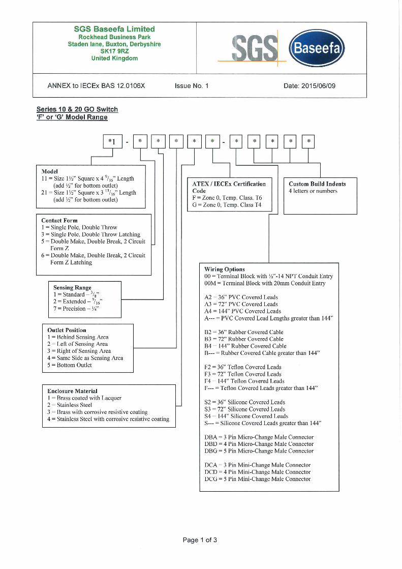
Series 10 & 20 GO Switch'F' or 'G' Model Range
Custom Build Indents4 letters or numbers
ATEX / IECEx CertificationCodeF = Zone 0, Temp. Class. T6G = Zone 0, Temp. Class T4
ModelII = Size I y," Square x 4 9/16" Length
(add y:," for bottom outlet)21 = Size 1y:," Square x 3 13/ 16" Length
(add W' for bottom outlet)
Contact FormI = Single Pole, Double Throw3 = Single Pole, Double Throw Latching5 = Double Make, Double Break, 2 Circuit
FormZ6 = Double Make, Double Break, 2 Circuit
Form Z Latching
Sensing Range1 = Standard - 3/8"
2 = Extended - 9/16"
7 = Precision - v."
Wiring Options00 = Terminal Block with y:'''-14 NPT Conduit EntryOOM = Terminal Block with 20mm Conduit Entry
Outlet PositionI = Behind Sensing Area2 = Left of Sensing Area3 = Right of Sensing Area4 = Same Side as Sensing Area5 = Bottom Outlet
Enclosure MaterialI = Brass coated with Lacquer2 = Stainless Steel3 = Brass with corrosive resistive coating4 = Stainless Steel with corrosive resistive coating
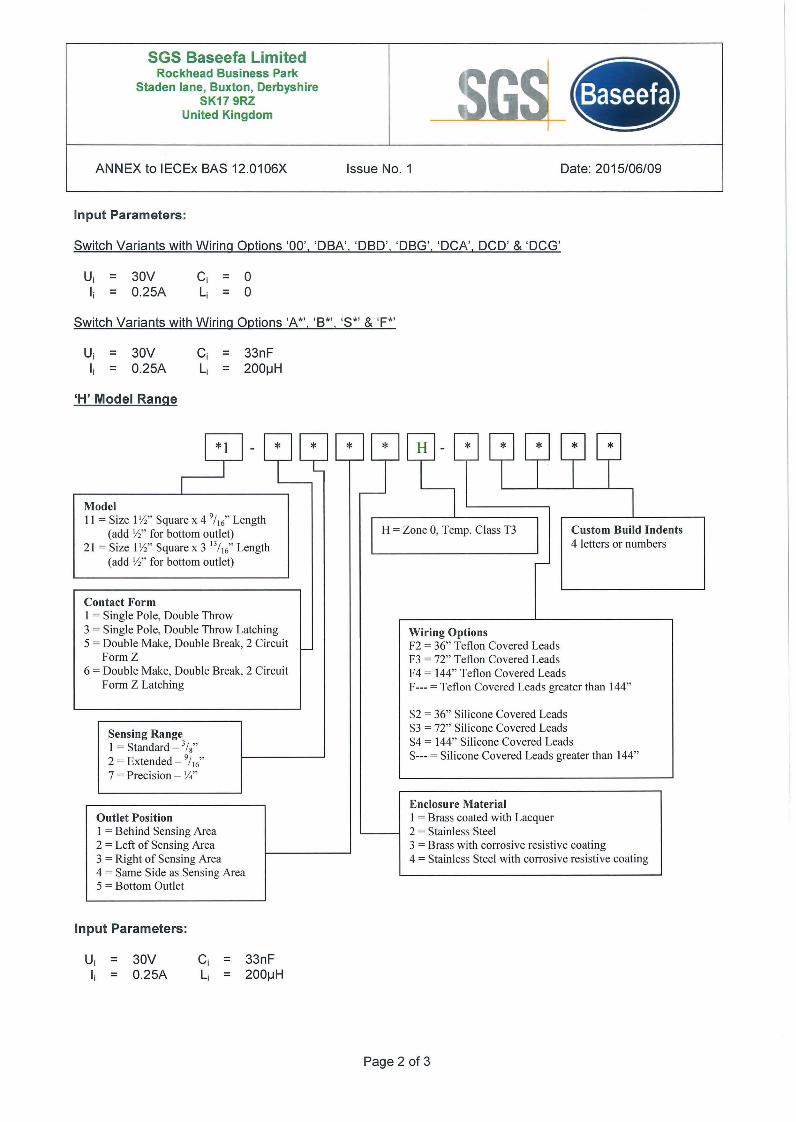
Input Parameters:
= 30V0.25A
33nF200IJH
Page 2 of 3
SGS Baseefa LimitedRockhead Business Park
Staden lane, Buxton, DerbyshireSK17 9RZ
United Kingdom • ....• • •
ANNEX to IECEx BAS 12.0106X
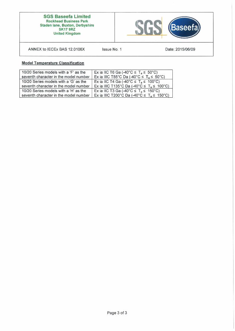
Model Temperature Classification
Issue No.1 Date: 2015/06/09
10/20 Series models with a 'F' as the Ex ia IIC T6 Ga (-40°C s; Ta s; 50°C)seventh character in the model number Ex ia IIiC T85°C Da (-40°C s; Ta s; 50°C)10/20 Series models with a 'G' as the Ex ia IIC T4 Ga (-40°C s; Ta s; 100°C)seventh character in the model number Ex ia IIiC T135°C Da (-40°C s; Ta s; 100°C)10/20 Series models with a 'H' as the Ex ia IIC T3 Ga (-40°C s; Ta s; 150°C)seventh character in the model number Ex ia IIiC T200°C Da (-40°C s; Ta s; 150°C)


![IECEx On-Line Certificate System Update €¦ · Dratt Certificate [admin] Certificate refl number First publication date [admin] To be accounted [admin] IECEx cert (Exca) Excas.](https://static.documents.pub/doc/80x56/5fc747ec1441036d884c74af/iecex-on-line-certificate-system-update-dratt-certificate-admin-certificate-refl.jpg)


