Adaptive signal amplitude for high frequency signal injection based sensor less PMSM drives Ravikumar Setty .A and Shashank Wekhande Avant Garde Solutions Pvt Ltd, (Consultant to Allegro Micro Systems, USA) Mumbai,India. Kishore Chatterjee Electrical Engg Department, IIT Bombay, Mumbai,India. Abstract— High frequency signal injection based sensor less techniques are well proven and reliable techniques to estimate rotor position from low speed to stand still. However these techniques distort motor currents, which introduce torque ripple and acoustic noise. Lower signal injection amplitude reduces torque ripple but increases position estimation error, so correct signal injection amplitude is required for satisfactory drive performance. More over signal injection amplitude required in transients is higher than steady state conditions. In this work signal amplitude is adaptively increased during transients based on rate of change of load and reduced back to original value under steady state. This work reports implementation details and simulation results of adaptive signal injection based sensor less control. Simulation results shows reduction in torque ripple Keywords— Sensor less control; High frequency signal injection; torque ripple; acoustic noise and adaptive signal injection. NOMENCLATURE PMBL Permanent Magnet Brush Less R Stator winding resistance / Phase L Stator winding inductance / Phase L d , L q Stator inductance of direct and quadrature axis components αβ Stator orthogonal coordinate system dq Rotor orthogonal coordinate system dq' Magnetic Saliency axis on rotor side. A 3 phase to 2 phase transformation matrix (Clark Transformation) B αβ to dq transformation matrix (Park transformation) T Transpose v c , i c High frequency voltage and high frequency current response L c High frequency stator inductance vector V DC DC Supply Voltage to Inverter I a ,I b ,I c Currents through Phase a, b and c respectively I ab1 I αβ rotated with injected frequency and filtered. θ r or λ dq’ Rotor Magnetic saliency Position angle reference to rotor orthogonal system. I. INTRODUCTION Permanent Magnet Brushless (PMBL) Motors are increasingly used in high performance applications. This is because PMBL motor has many features, like high efficiency, compactness, high torque to inertia ratio and good dynamic response. High frequency signal injection based sensor less control techniques are widely accepted due to their robustness at low speed to standstill. According to the type of signal injected these are classified into rotating injection [1]-[3] and pulsating [4]-[6] injection. In all these methods high frequency signal is super imposed on fundamental excitation and resulting high frequency current response is demodulated to extract rotor position information. These high frequency signals super imposed on fundamental components distort the phase currents and introduce torque ripple and acoustic noise. The amplitude and frequency of the injected signal to be chosen carefully to ensure that undesirable torque ripples can be minimized. The amplitude of the injected signal will be small thus making it particularly susceptible to interference from nonlinear distortion effects [7], [8], but results in reduced position estimation, signal injection amplitude cannot be reduced below certain threshold level. If this level is optimized to steady state conditions, which is not enough in transient condition as the high frequency current response distorts and reduces the signal to noise ratio. [9] Uses oversampling approach and [10] uses delta-sigma AD conversion techniques to improve the signal to noise ration and allows to minimize the signal amplitude, doesn’t indicate drive performance during transient conditions. This work studies the requirements of signal amplitude under steady state and transient conditions. Lower signal injection amplitude results in increased estimated position error and higher signal injection amplitude results in torque pulsations and audible noise. To trade off between torque pulsations and position error optimum amplitude of signal injection is necessary. Current work proposed adaptive signal
Transcript
Adaptive signal amplitude for high frequency signal
injection based sensor less PMSM drives
Ravikumar Setty .A and Shashank Wekhande Avant Garde Solutions Pvt Ltd,
(Consultant to Allegro Micro Systems, USA)
Mumbai,India.
Kishore Chatterjee Electrical Engg Department,
IIT Bombay,
Mumbai,India.
Abstract— High frequency signal injection based sensor less
techniques are well proven and reliable techniques to estimate
rotor position from low speed to stand still. However these
techniques distort motor currents, which introduce torque ripple
and acoustic noise. Lower signal injection amplitude reduces
torque ripple but increases position estimation error, so correct
signal injection amplitude is required for satisfactory drive
performance. More over signal injection amplitude required in
transients is higher than steady state conditions. In this work
signal amplitude is adaptively increased during transients based
on rate of change of load and reduced back to original value
under steady state. This work reports implementation details and
simulation results of adaptive signal injection based sensor less
control. Simulation results shows reduction in torque ripple
Keywords— Sensor less control; High frequency signal
injection; torque ripple; acoustic noise and adaptive signal
injection.
NOMENCLATURE
PMBL Permanent Magnet Brush Less
R Stator winding resistance / Phase
L Stator winding inductance / Phase
Ld, Lq Stator inductance of direct and quadrature
axis components
αβ Stator orthogonal coordinate system
dq Rotor orthogonal coordinate system
dq' Magnetic Saliency axis on rotor side.
A 3 phase to 2 phase transformation matrix
(Clark Transformation)
B αβ to dq transformation matrix
(Park transformation)
T Transpose
vc, ic High frequency voltage and high
frequency current response
Lc High frequency stator inductance vector
VDC DC Supply Voltage to Inverter
Ia,Ib,Ic Currents through Phase a, b and c
respectively
Iab1 Iαβ rotated with injected frequency and
filtered.
θr or λdq’ Rotor Magnetic saliency Position angle
reference to rotor orthogonal system.
I. INTRODUCTION
Permanent Magnet Brushless (PMBL) Motors are
increasingly used in high performance applications. This is
because PMBL motor has many features, like high efficiency,
compactness, high torque to inertia ratio and good dynamic
response. High frequency signal injection based sensor less
control techniques are widely accepted due to their robustness
at low speed to standstill. According to the type of signal
injected these are classified into rotating injection [1]-[3] and
pulsating [4]-[6] injection. In all these methods high frequency
signal is super imposed on fundamental excitation and
resulting high frequency current response is demodulated to
extract rotor position information. These high frequency
signals super imposed on fundamental components distort the
phase currents and introduce torque ripple and acoustic noise.
The amplitude and frequency of the injected signal to be
chosen carefully to ensure that undesirable torque ripples can
be minimized. The amplitude of the injected signal will be
small thus making it particularly susceptible to interference
from nonlinear distortion effects [7], [8], but results in reduced
position estimation, signal injection amplitude cannot be
reduced below certain threshold level. If this level is
optimized to steady state conditions, which is not enough in
transient condition as the high frequency current response
distorts and reduces the signal to noise ratio. [9] Uses
oversampling approach and [10] uses delta-sigma AD
conversion techniques to improve the signal to noise ration
and allows to minimize the signal amplitude, doesn’t indicate
drive performance during transient conditions.
This work studies the requirements of signal amplitude
under steady state and transient conditions. Lower signal
injection amplitude results in increased estimated position
error and higher signal injection amplitude results in torque
pulsations and audible noise. To trade off between torque
pulsations and position error optimum amplitude of signal
injection is necessary. Current work proposed adaptive signal
amplitude based sensor less control to reduce the torque ripple
and acoustic noise. Which is then verified using simulations.
II. ADAPTIVE SIGNAL INJECTION BASED SENSOR LESS
CONTROL
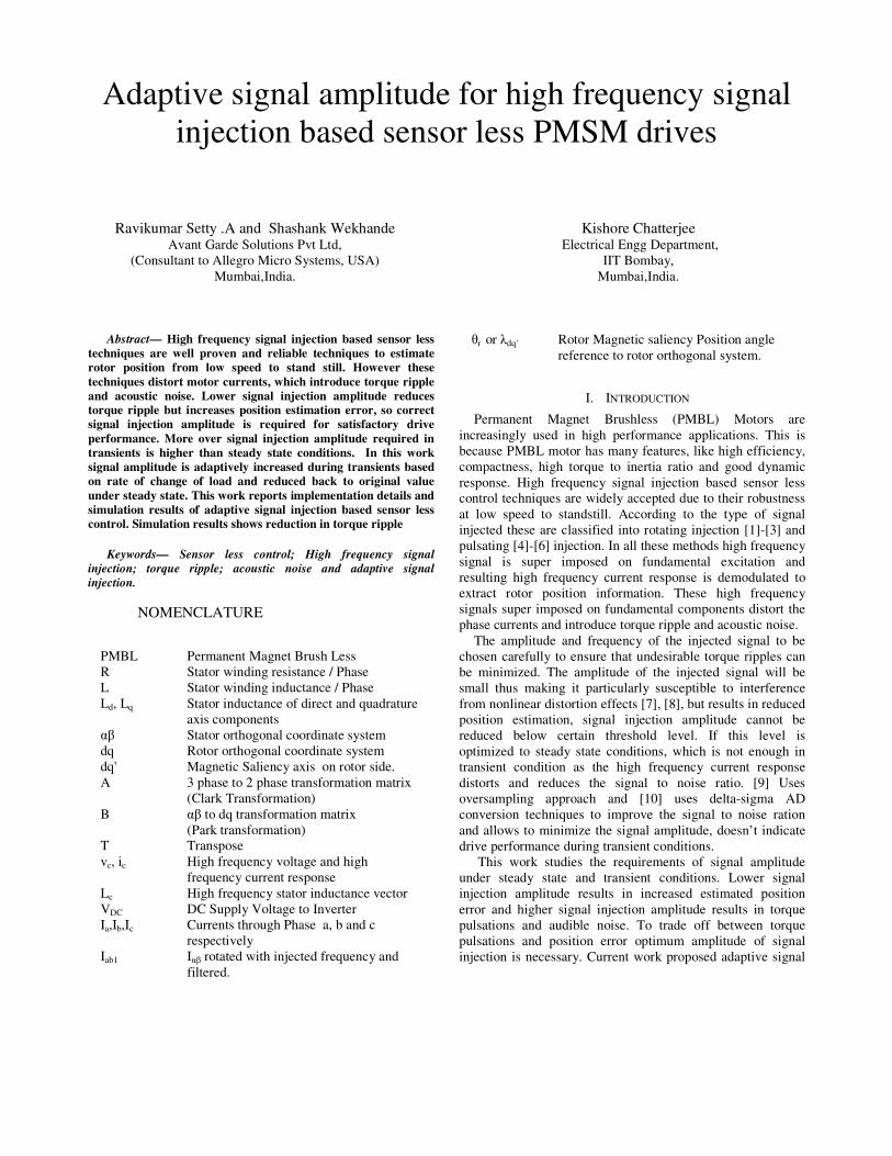
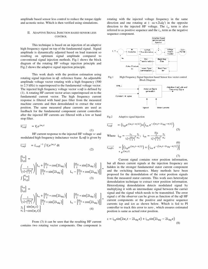
This technique is based on an injection of an adaptive
high frequency signal on top of the fundamental signal. Signal
amplitude is dynamically adjusted based on load transient so
resulting on optimum signal amplitude compared to
conventional signal injection methods. Fig.1 shows the block
diagram of the rotating HF voltage injection principle and
Fig.2 shows the adaptive signal injection principle.
This work deals with the position estimation using
rotating signal injection in αβ -reference frame. An adjustable
amplitude voltage vector rotating with a high frequency (500
to 2.5 kHz) is superimposed to the fundamental voltage vector.
The injected high frequency voltage vector vcαβ is defined by
(1). A rotating HF current vector arises superimposed on to the
fundamental current vector. The high frequency current
response is filtered with band pass filter from the measured
machine currents and then demodulated to extract the rotor
position. The same measured phase currents are used as
feedback for the fundamental component current controllers
after the injected HF currents are filtered with a low or band
stop filter.
������������� � ��� �
(1)
HF current response to the injected HF voltage vc and
modulated high frequency inductance vector Lcαβ is given by