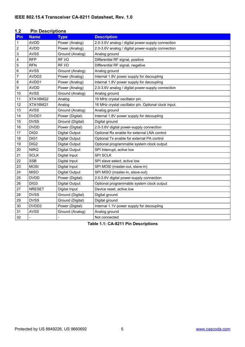
IEEE 802.15.4 Transceiver CA-8211 Datasheet Rev. 1.0, January 2019 GENERAL DESCRIPTION The CA-8211 SMARTRange™ is a fully-featured Thread- certified transceiver modem solution for IEEE 802.15.4 communications in the 2.4GHz band. With industry leading power consumption and sensitivity performance it delivers unparalleled range without external amplifier components, thus providing whole-house connectivity in any market on the planet. PHY and MAC support functions and system configuration are programmed via an intelligent co-processor, thereby minimizing the control overhead for the system host. Unlike PHY-only devices, the CA-8211 API interface is insensitive to the timing of commands on the SPI bus. The CA-8211 can therefore be controlled directly from Linux, or your existing MCU, allowing you to concentrate on your application, without the need to worry about PHY standards compliance. FEATURES ● High performance SMARTRange™ transceiver modem ● Thread Certified Component for every role ● Compliant to IEEE 802.15.4-2006 and IEEE 802.15.4-2003 ● Industrial temperature range: -40°C to +85°C ● Wide supply voltage range: 2.1V to 3.6V ● Integrated MAC on low-power co-processor for a clean API ● Highly optimized, robust and heavily tested Radio Features ● Industry-leading receive sensitivity of -105dBm ● Programmable transmit power of -3dBm to +9dBm ● Industry-leading link budget of 114dB Low-Power Features ● Industry leading power consumption 1 Active mode (CPU Idle): Tx: 12mA at 0dBm transmit power 19mA at +9dBm transmit power Rx: 10mA at -100dBm sensitivity 14mA at -105dBm sensitivity ● Multiple options for sleep and power saving modes ● Sleep mode currents: 32kHz Sleep timer 200nA IEEE 802.15.4-2006 MAC Hardware Support ● Automatic Frame Check Sequence (FCS) generation, analysis and filtering ● Auto-Acknowledgements ● Automatic frame filtering and address validation ● Energy Detection (ED, RSSI) and Carrier Sense (CS) ● Clear Channel Assessment (CCA) for CSMA-CA algorithm ● AES security hardware accelerator ● Random Number Generator Simplified API ● IEEE 802.15.4 MAC managed by on-chip co-processor ● SAP interface, following the IEEE 802.15.4 specification ● Additional commands for advanced & nonstandard behavior ● Synchronous SAP commands simplify user software ● All real-time requirements are handled by the CA-8211 ● Optimized & robust SPI interface 1 VDD = 3V, f = 2.45 GHz, Top = 25°C Configurable GPIO interface: ● SPI serial interface ● Interrupt output ● Configurable system clock outputs ● Configurable control outputs for transmit and receive enable Package ● Available in a 32-PIN low-profile QFN package Package size 5mm x 5mm x 0.9mm Development Tools ● IEEE 802.15.4-2006 MLME/MCPS API ● Certified Thread stack based on openthread ● Wide range of supported platforms, Linux, ARM ® , MIPS ® ● Seamless Linux prototyping suite to access API over USB for rapid development BENEFITS Equipment cost: Increased range removes the need for external power amplifiers, thereby reducing component BOM. Installation cost: Greater datalink reliability lessens the need for skilled installers, and the consumer can self-install. Maintenance cost: Lower power consumption means that batteries last longer, thereby minimizing maintenance cost. APPLICATIONS ● Home and building automation ● Consumer electronics & cellphone ● Lighting systems ● Heating, ventilation & air-conditioning systems (HVAC) ● Smart grid (AMI/AMR) ● Asset tracking (active RFID) ● Industrial control and monitoring ● Assisted living & telecare PIN CONFGURATION AVDD1 8 AVDD2 7 AVSS 6 RFN 5 RFP 4 AVSS 3 AVDD 2 AVDD 1 XTA16MQ2 11 AVSS 10 AVSS 13 DVSS 15 DVDD1 14 DVDD 16 17 DIG0 18 DIG1 19 DIG2 20 NIRQ 21 SCLK 22 SSB 23 MOSI 24 MISO XTA16MQ1 12 AVDD 9 die attach pad Protected by US 8849226, US 9660692 1 www.cascoda.com and corresponding rights in other territories
Transcript
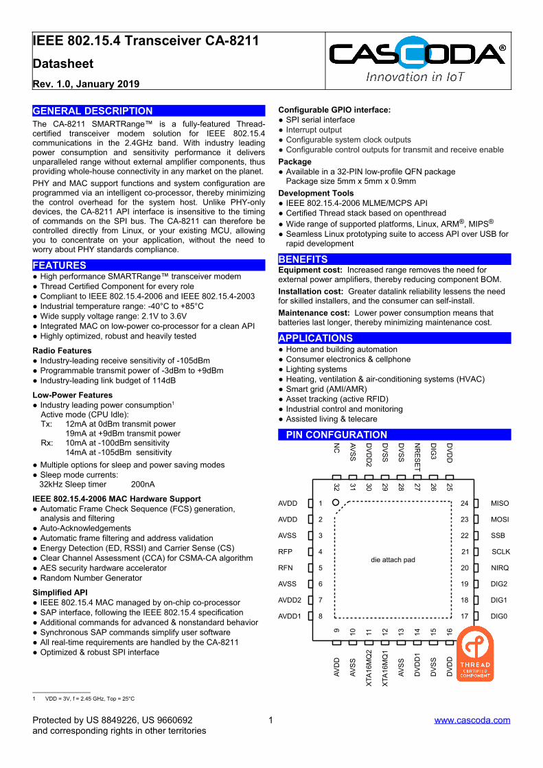
IEEE 802.15.4 Transceiver CA-8211
Datasheet
Rev. 1.0, January 2019
GENERAL DESCRIPTIONThe CA-8211 SMARTRange™ is a fully-featured Thread-certified transceiver modem solution for IEEE 802.15.4communications in the 2.4GHz band. With industry leadingpower consumption and sensitivity performance it deliversunparalleled range without external amplifier components, thusproviding whole-house connectivity in any market on the planet.
PHY and MAC support functions and system configuration areprogrammed via an intelligent co-processor, thereby minimizingthe control overhead for the system host. Unlike PHY-onlydevices, the CA-8211 API interface is insensitive to the timingof commands on the SPI bus. The CA-8211 can therefore becontrolled directly from Linux, or your existing MCU, allowingyou to concentrate on your application, without the need toworry about PHY standards compliance.
FEATURES● High performance SMARTRange™ transceiver modem● Thread Certified Component for every role● Compliant to IEEE 802.15.4-2006 and IEEE 802.15.4-2003● Industrial temperature range: -40°C to +85°C● Wide supply voltage range: 2.1V to 3.6V● Integrated MAC on low-power co-processor for a clean API● Highly optimized, robust and heavily tested
Radio Features● Industry-leading receive sensitivity of -105dBm● Programmable transmit power of -3dBm to +9dBm● Industry-leading link budget of 114dB
Low-Power Features● Industry leading power consumption1
Active mode (CPU Idle):Tx: 12mA at 0dBm transmit power 19mA at +9dBm transmit powerRx: 10mA at -100dBm sensitivity 14mA at -105dBm sensitivity
● Multiple options for sleep and power saving modes● Sleep mode currents: 32kHz Sleep timer 200nA
analysis and filtering● Auto-Acknowledgements● Automatic frame filtering and address validation● Energy Detection (ED, RSSI) and Carrier Sense (CS)● Clear Channel Assessment (CCA) for CSMA-CA algorithm● AES security hardware accelerator● Random Number Generator
Simplified API● IEEE 802.15.4 MAC managed by on-chip co-processor● SAP interface, following the IEEE 802.15.4 specification● Additional commands for advanced & nonstandard behavior● Synchronous SAP commands simplify user software● All real-time requirements are handled by the CA-8211● Optimized & robust SPI interface
1 VDD = 3V, f = 2.45 GHz, Top = 25°C
Configurable GPIO interface:● SPI serial interface● Interrupt output● Configurable system clock outputs● Configurable control outputs for transmit and receive enable
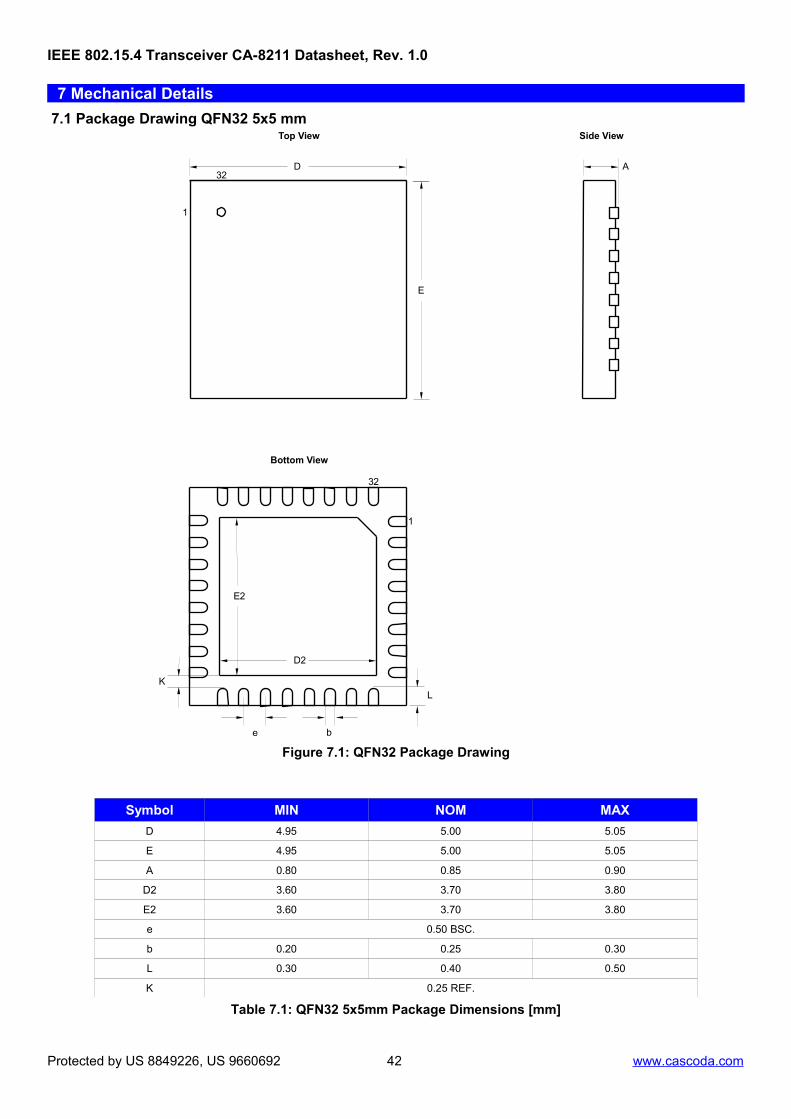
Package● Available in a 32-PIN low-profile QFN package
Package size 5mm x 5mm x 0.9mm
Development Tools● IEEE 802.15.4-2006 MLME/MCPS API● Certified Thread stack based on openthread● Wide range of supported platforms, Linux, ARM®, MIPS®
● Seamless Linux prototyping suite to access API over USB for rapid development
BENEFITSEquipment cost: Increased range removes the need for external power amplifiers, thereby reducing component BOM.
Installation cost: Greater datalink reliability lessens the need for skilled installers, and the consumer can self-install.
Maintenance cost: Lower power consumption means that batteries last longer, thereby minimizing maintenance cost.
APPLICATIONS● Home and building automation● Consumer electronics & cellphone● Lighting systems● Heating, ventilation & air-conditioning systems (HVAC)● Smart grid (AMI/AMR)● Asset tracking (active RFID)● Industrial control and monitoring● Assisted living & telecare
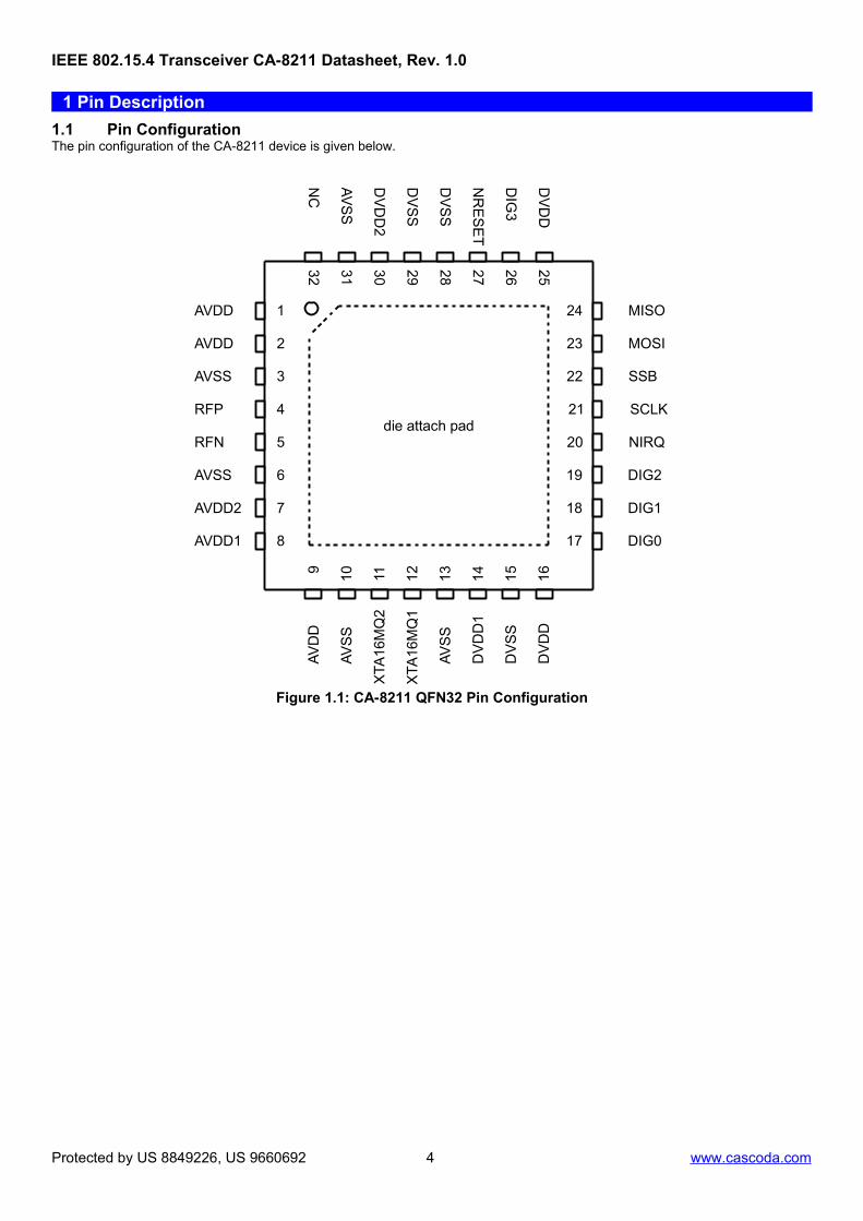
PIN CONFGURATION
AVDD1 8
AVDD2 7
AVSS 6
RFN 5
RFP 4
AVSS 3
AVDD 2
AVDD 1
XTA
16M
Q2
11
AV
SS
10
AV
SS
13
DV
SS
15
DV
DD
114
DV
DD
16
17 DIG0
18 DIG1
19 DIG2
20 NIRQ
21 SCLK
22 SSB
23 MOSI
24 MISO
XTA
16M
Q1
12
AV
DD
9
die attach pad
Protected by US 8849226, US 9660692 1 www.cascoda.comand corresponding rights in other territories
4.5.1 Energy Detect (ED), Carrier Sense (CS) and Clear Channel Assessment (CCA)...........................................................13 4.5.2 AES Encryption Engine.................................................................................................................................................... 14 4.5.3 Random Number Generator.............................................................................................................................................14
4.6 MAC Co-processor................................................................................................................................................................... 14 4.7 Low-Power Modes.................................................................................................................................................................... 14 4.8 System Clock Output................................................................................................................................................................ 15 4.9 System Clock Input.................................................................................................................................................................. 15 4.10 Support for external PA and LNA...........................................................................................................................................15
5 SPI Communications Interface......................................................................................................................................................... 16 5.1 SPI Physical Specification........................................................................................................................................................ 16 5.2 SPI Protocol Message Encapsulation and Data Exchange......................................................................................................17
5.2.1 Message Encapsulation................................................................................................................................................... 17 5.2.2 Data Exchange between Master and Slave.....................................................................................................................18
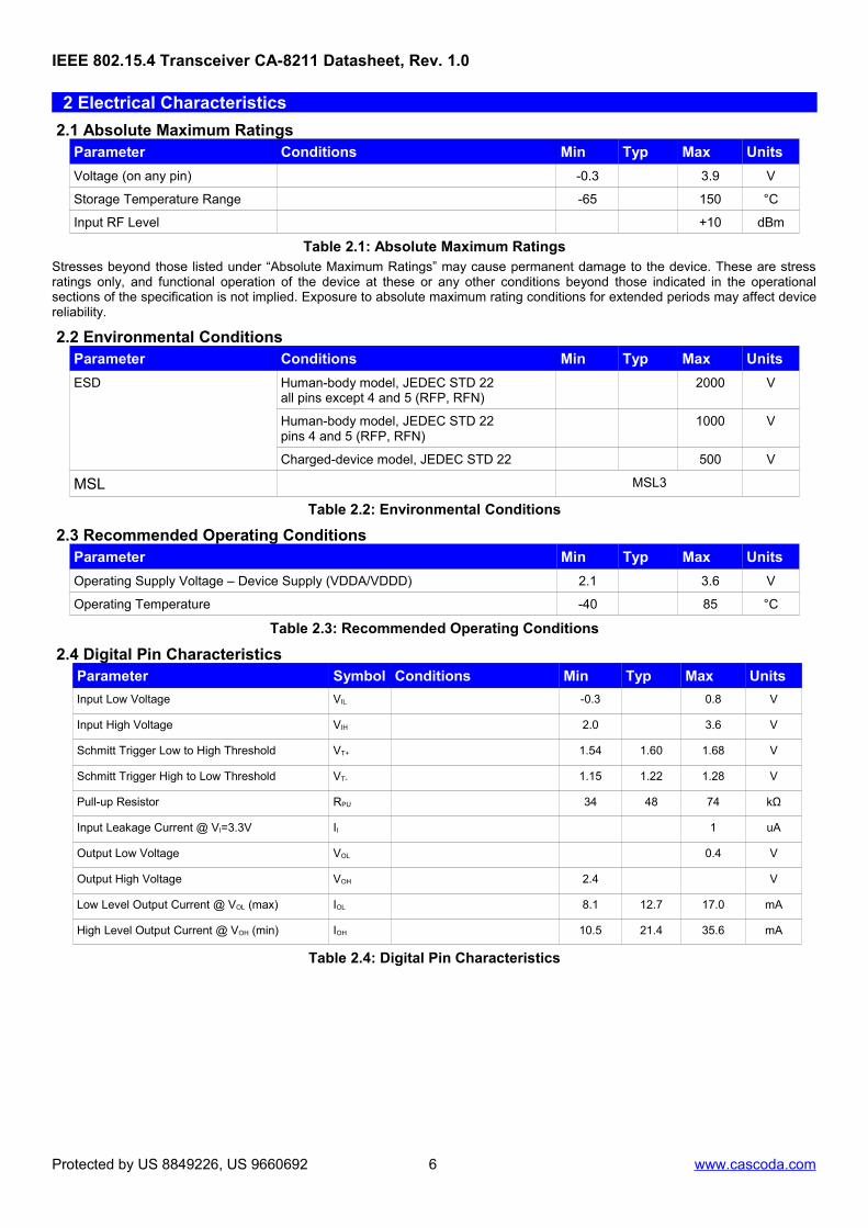
2.1 Absolute Maximum RatingsParameter Conditions Min Typ Max Units
Voltage (on any pin) -0.3 3.9 V
Storage Temperature Range -65 150 °C
Input RF Level +10 dBm
Table 2.1: Absolute Maximum RatingsStresses beyond those listed under “Absolute Maximum Ratings” may cause permanent damage to the device. These are stressratings only, and functional operation of the device at these or any other conditions beyond those indicated in the operationalsections of the specification is not implied. Exposure to absolute maximum rating conditions for extended periods may affect devicereliability.
2.2 Environmental ConditionsParameter Conditions Min Typ Max Units
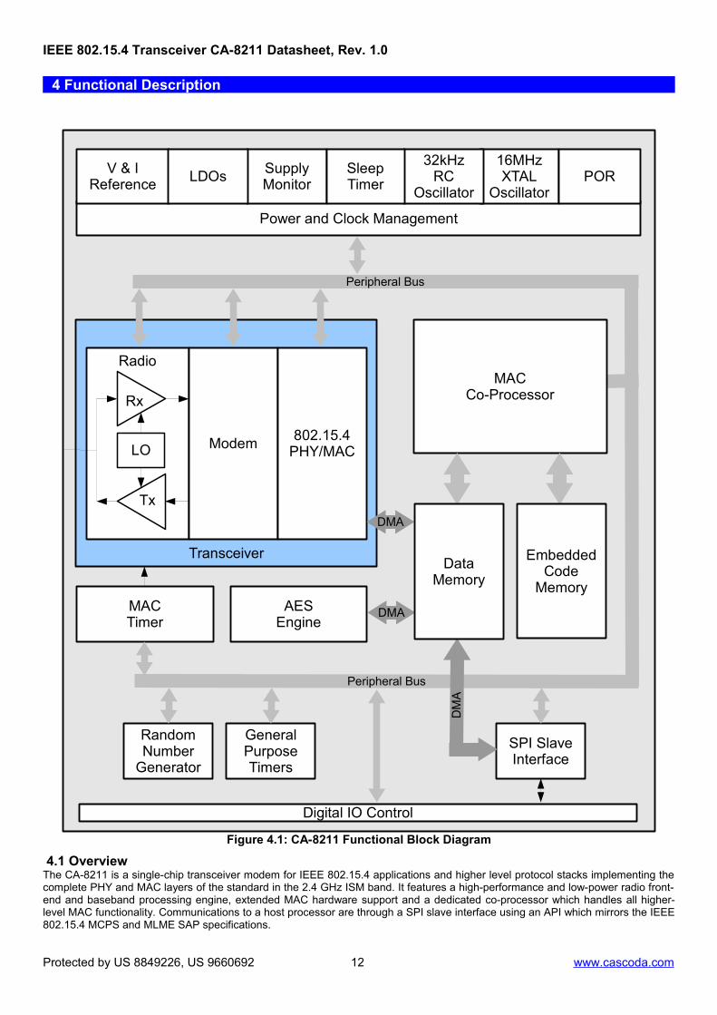
4.1 OverviewThe CA-8211 is a single-chip transceiver modem for IEEE 802.15.4 applications and higher level protocol stacks implementing thecomplete PHY and MAC layers of the standard in the 2.4 GHz ISM band. It features a high-performance and low-power radio front-end and baseband processing engine, extended MAC hardware support and a dedicated co-processor which handles all higher-level MAC functionality. Communications to a host processor are through a SPI slave interface using an API which mirrors the IEEE802.15.4 MCPS and MLME SAP specifications.
Protected by US 8849226, US 9660692 12 www.cascoda.com
4.2 Receiver (Rx)The differential signal at pins RFP and RFN is amplified primarily by a Low Noise Amplifier (LNA) and then down-converted in thereceive section. A baseband amplification chain amplifies the down-converted signal further until it can be digitized by an ADC. Allrequired filtering is performed on-chip without the need for external filter components. A demodulator with a novel energy-efficientand high-performance architecture correlates the data and extracts the data symbols. The digital section also controls the gainthrough the amplification path, and extracts values for Energy Detect (ED, or RSSI) and Carrier Sense (CS), which are used by theMAC for Clear Channel Assessment (CCA) and reported for routing and other purposes.
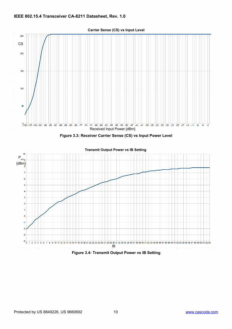
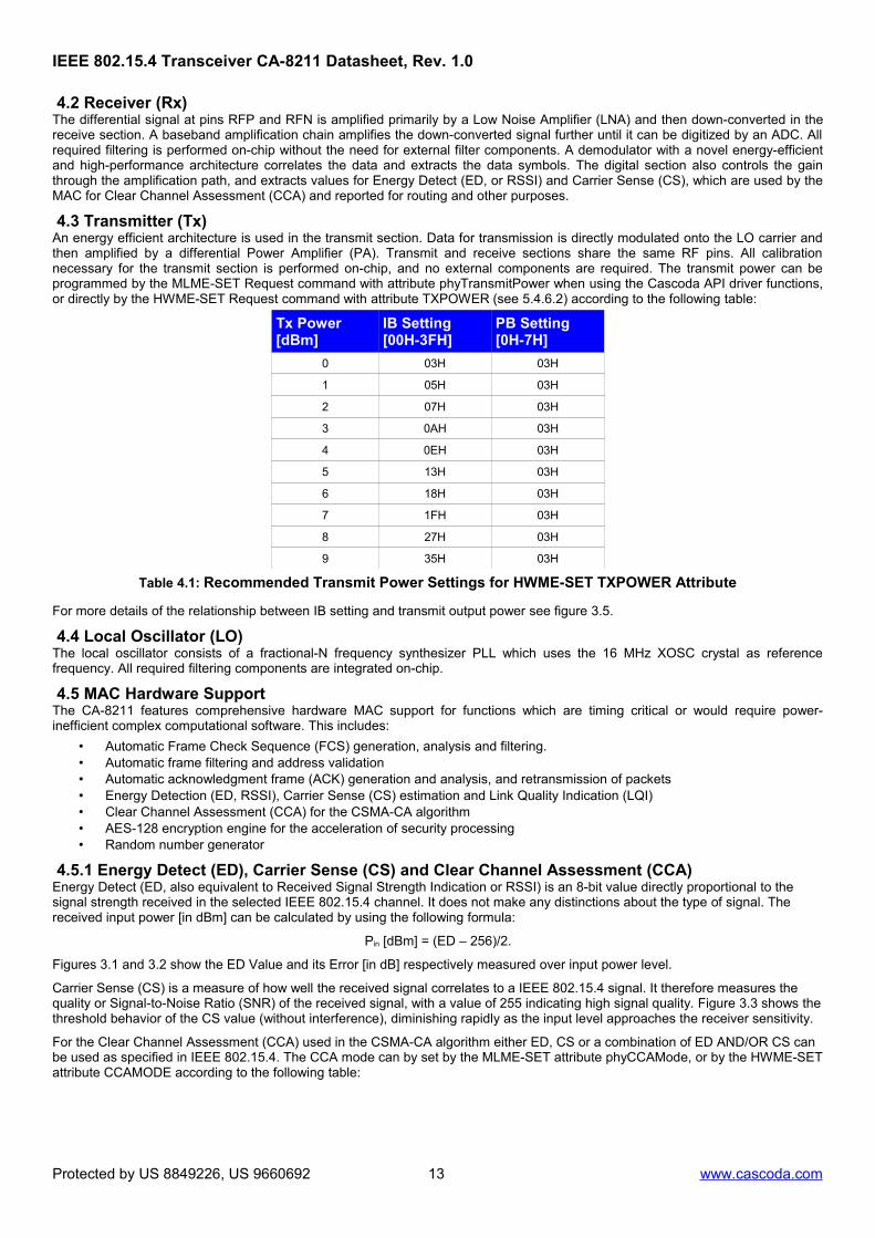
4.3 Transmitter (Tx) An energy efficient architecture is used in the transmit section. Data for transmission is directly modulated onto the LO carrier andthen amplified by a differential Power Amplifier (PA). Transmit and receive sections share the same RF pins. All calibrationnecessary for the transmit section is performed on-chip, and no external components are required. The transmit power can beprogrammed by the MLME-SET Request command with attribute phyTransmitPower when using the Cascoda API driver functions,or directly by the HWME-SET Request command with attribute TXPOWER (see 5.4.6.2) according to the following table:
Tx Power[dBm]
IB Setting[00H-3FH]
PB Setting[0H-7H]
0 03H 03H
1 05H 03H
2 07H 03H
3 0AH 03H
4 0EH 03H
5 13H 03H
6 18H 03H
7 1FH 03H
8 27H 03H
9 35H 03H
Table 4.1: Recommended Transmit Power Settings for HWME-SET TXPOWER Attribute
For more details of the relationship between IB setting and transmit output power see figure 3.5.
4.4 Local Oscillator (LO)The local oscillator consists of a fractional-N frequency synthesizer PLL which uses the 16 MHz XOSC crystal as referencefrequency. All required filtering components are integrated on-chip.
4.5 MAC Hardware SupportThe CA-8211 features comprehensive hardware MAC support for functions which are timing critical or would require power-inefficient complex computational software. This includes:
• Automatic Frame Check Sequence (FCS) generation, analysis and filtering.• Automatic frame filtering and address validation• Automatic acknowledgment frame (ACK) generation and analysis, and retransmission of packets• Energy Detection (ED, RSSI), Carrier Sense (CS) estimation and Link Quality Indication (LQI)• Clear Channel Assessment (CCA) for the CSMA-CA algorithm• AES-128 encryption engine for the acceleration of security processing• Random number generator
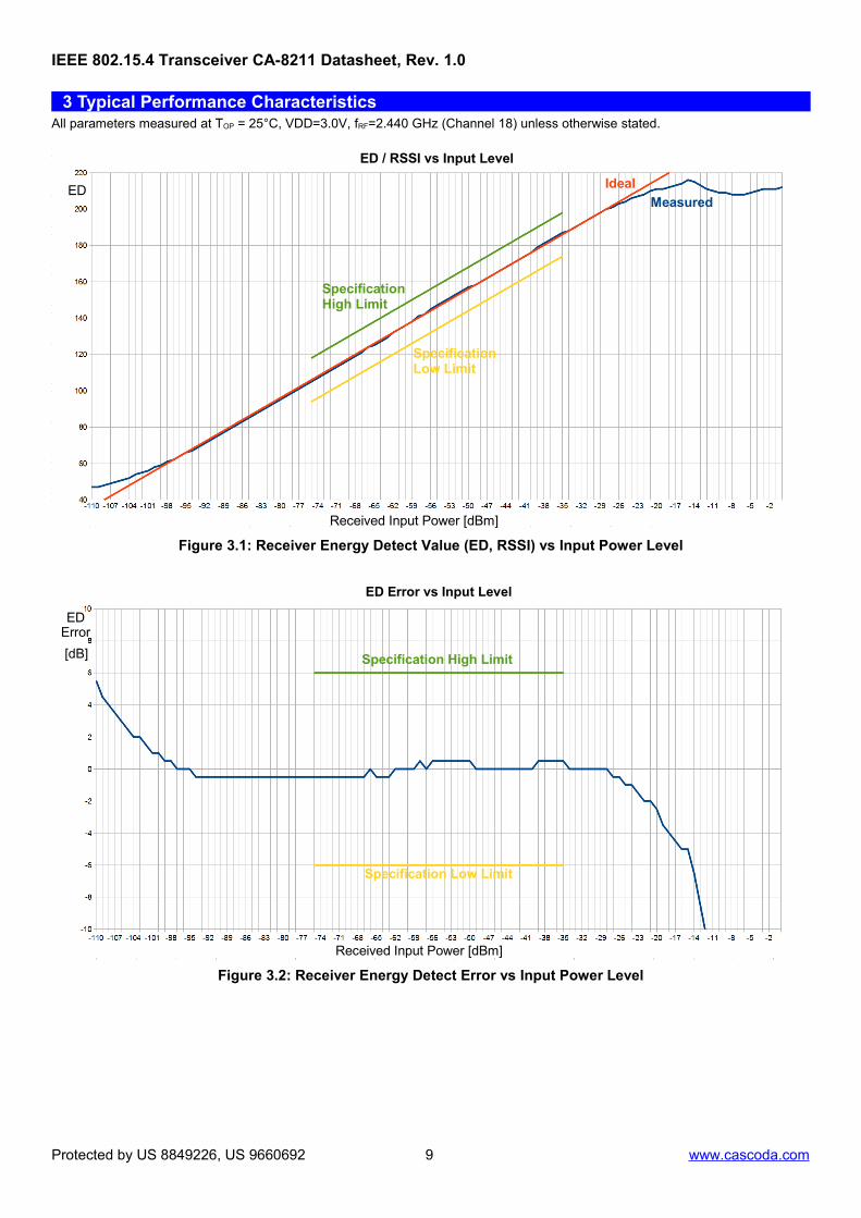
4.5.1 Energy Detect (ED), Carrier Sense (CS) and Clear Channel Assessment (CCA)Energy Detect (ED, also equivalent to Received Signal Strength Indication or RSSI) is an 8-bit value directly proportional to the signal strength received in the selected IEEE 802.15.4 channel. It does not make any distinctions about the type of signal. The received input power [in dBm] can be calculated by using the following formula:
Pin [dBm] = (ED – 256)/2.
Figures 3.1 and 3.2 show the ED Value and its Error [in dB] respectively measured over input power level.
Carrier Sense (CS) is a measure of how well the received signal correlates to a IEEE 802.15.4 signal. It therefore measures the quality or Signal-to-Noise Ratio (SNR) of the received signal, with a value of 255 indicating high signal quality. Figure 3.3 shows thethreshold behavior of the CS value (without interference), diminishing rapidly as the input level approaches the receiver sensitivity.
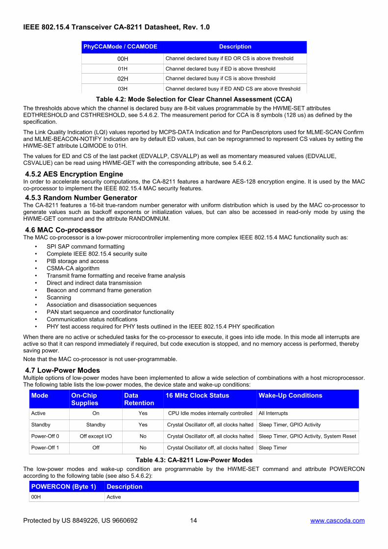
For the Clear Channel Assessment (CCA) used in the CSMA-CA algorithm either ED, CS or a combination of ED AND/OR CS can be used as specified in IEEE 802.15.4. The CCA mode can by set by the MLME-SET attribute phyCCAMode, or by the HWME-SETattribute CCAMODE according to the following table:
Protected by US 8849226, US 9660692 13 www.cascoda.com
00H Channel declared busy if ED OR CS is above threshold
01H Channel declared busy if ED is above threshold
02H Channel declared busy if CS is above threshold
03H Channel declared busy if ED AND CS are above threshold
Table 4.2: Mode Selection for Clear Channel Assessment (CCA)The thresholds above which the channel is declared busy are 8-bit values programmable by the HWME-SET attributes EDTHRESHOLD and CSTHRESHOLD, see 5.4.6.2. The measurement period for CCA is 8 symbols (128 us) as defined by the specification.
The Link Quality Indication (LQI) values reported by MCPS-DATA Indication and for PanDescriptors used for MLME-SCAN Confirmand MLME-BEACON-NOTIFY Indication are by default ED values, but can be reprogrammed to represent CS values by setting the HWME-SET attribute LQIMODE to 01H.
The values for ED and CS of the last packet (EDVALLP, CSVALLP) as well as momentary measured values (EDVALUE, CSVALUE) can be read using HWME-GET with the corresponding attribute, see 5.4.6.2.
4.5.2 AES Encryption EngineIn order to accelerate security computations, the CA-8211 features a hardware AES-128 encryption engine. It is used by the MACco-processor to implement the IEEE 802.15.4 MAC security features.
4.5.3 Random Number GeneratorThe CA-8211 features a 16-bit true-random number generator with uniform distribution which is used by the MAC co-processor togenerate values such as backoff exponents or initialization values, but can also be accessed in read-only mode by using theHWME-GET command and the attribute RANDOMNUM.
4.6 MAC Co-processorThe MAC co-processor is a low-power microcontroller implementing more complex IEEE 802.15.4 MAC functionality such as:
• SPI SAP command formatting• Complete IEEE 802.15.4 security suite• PIB storage and access• CSMA-CA algorithm• Transmit frame formatting and receive frame analysis• Direct and indirect data transmission• Beacon and command frame generation• Scanning• Association and disassociation sequences• PAN start sequence and coordinator functionality• Communication status notifications• PHY test access required for PHY tests outlined in the IEEE 802.15.4 PHY specification
When there are no active or scheduled tasks for the co-processor to execute, it goes into idle mode. In this mode all interrupts are active so that it can respond immediately if required, but code execution is stopped, and no memory access is performed, thereby saving power.
Note that the MAC co-processor is not user-programmable.
4.7 Low-Power ModesMultiple options of low-power modes have been implemented to allow a wide selection of combinations with a host microprocessor.The following table lists the low-power modes, the device state and wake-up conditions:
Mode On-Chip Supplies
Data Retention
16 MHz Clock Status Wake-Up Conditions
Active On Yes CPU Idle modes internally controlled All Interrupts
Power-Off 0 Off except I/O No Crystal Oscillator off, all clocks halted Sleep Timer, GPIO Activity, System Reset
Power-Off 1 Off No Crystal Oscillator off, all clocks halted Sleep Timer
Table 4.3: CA-8211 Low-Power ModesThe low-power modes and wake-up condition are programmable by the HWME-SET command and attribute POWERCONaccording to the following table (see also 5.4.6.2):
POWERCON (Byte 1) Description
00H Active
Protected by US 8849226, US 9660692 14 www.cascoda.com
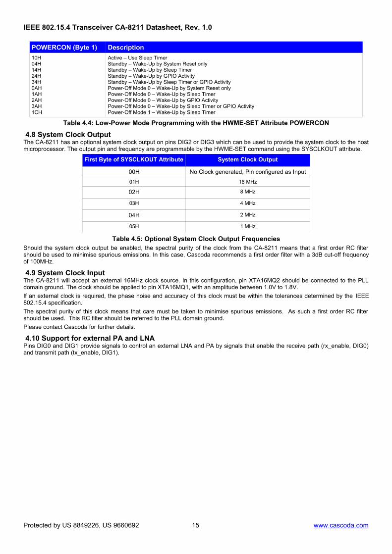
Active – Use Sleep TimerStandby – Wake-Up by System Reset onlyStandby – Wake-Up by Sleep TimerStandby – Wake-Up by GPIO ActivityStandby – Wake-Up by Sleep Timer or GPIO ActivityPower-Off Mode 0 – Wake-Up by System Reset onlyPower-Off Mode 0 – Wake-Up by Sleep TimerPower-Off Mode 0 – Wake-Up by GPIO ActivityPower-Off Mode 0 – Wake-Up by Sleep Timer or GPIO ActivityPower-Off Mode 1 – Wake-Up by Sleep Timer
Table 4.4: Low-Power Mode Programming with the HWME-SET Attribute POWERCON
4.8 System Clock OutputThe CA-8211 has an optional system clock output on pins DIG2 or DIG3 which can be used to provide the system clock to the hostmicroprocessor. The output pin and frequency are programmable by the HWME-SET command using the SYSCLKOUT attribute.
First Byte of SYSCLKOUT Attribute System Clock Output
00H No Clock generated, Pin configured as Input
01H 16 MHz
02H 8 MHz
03H 4 MHz
04H 2 MHz
05H 1 MHz
Table 4.5: Optional System Clock Output FrequenciesShould the system clock output be enabled, the spectral purity of the clock from the CA-8211 means that a first order RC filtershould be used to minimise spurious emissions. In this case, Cascoda recommends a first order filter with a 3dB cut-off frequencyof 100MHz.
4.9 System Clock InputThe CA-8211 will accept an external 16MHz clock source. In this configuration, pin XTA16MQ2 should be connected to the PLLdomain ground. The clock should be applied to pin XTA16MQ1, with an amplitude between 1.0V to 1.8V.
If an external clock is required, the phase noise and accuracy of this clock must be within the tolerances determined by the IEEE802.15.4 specification.
The spectral purity of this clock means that care must be taken to minimise spurious emissions. As such a first order RC filtershould be used. This RC filter should be referred to the PLL domain ground.
Please contact Cascoda for further details.
4.10 Support for external PA and LNAPins DIG0 and DIG1 provide signals to control an external LNA and PA by signals that enable the receive path (rx_enable, DIG0)and transmit path (tx_enable, DIG1).
Protected by US 8849226, US 9660692 15 www.cascoda.com
5 SPI Communications InterfaceThis section describes the CA-8211 SPI serial port slave interface protocol and defines the MAC level API for communicationsbetween a host processor acting as master and the CA-8211 transceiver modem chip as slave of a physical SPI interface.
The API is mainly defined by the transfer of IEEE 802.15.4-2006 MAC layer MCPS-SAP and MLME-SAP primitives. A Physicallayer Common Part Sublayer (PCPS) entity allows access to the IEEE802.15.4-2006 Physical Layer (PHY) data payload (Psdu). Ahardware management entity (HWME) has been added for handling control and status information which is not defined in the802.15.4 specification. The HWME is used for example for controlling power saving modes of the chip. The concept of serviceprimitives used in 802.15.4 has been maintained, with Request and Response primitives being transferred from the host to themodem, and Indication and Confirm primitives being transferred from the modem to the host. Also, a test and debug managemententity (TDME) has been added to allow running PHY tests according to the IEEE 802.15.4-2006 PHY layer implementation andgeneral RF test procedures.
5.1 SPI Physical SpecificationSerial data on the MOSI and MISO pins is synchronous to the serial clock, and is transmitted and received as 8-bit characters, MSBfirst. Data is usually expected in bursts (packets), with multiple bytes being transmitted in one access (without the chip select pinSSB being de-asserted).
In addition to the SPI interface pins SCLK, MOSI and MISO, a GPIO pin is required as interrupt (NIRQ) to indicate to the host thatthe slave has information (Indication or Confirm primitive) to be transferred. Although most microcontroller families provide adedicated slave select signal (SSB, active low), the functionality is sometimes limited and fixed to one or several bytes of transferlength. In all cases a GPIO pin can be used to generate the slave select. The device reset (NRESET) can be controlled by a hostprocessor GPIO, or can be connected to a common system reset.
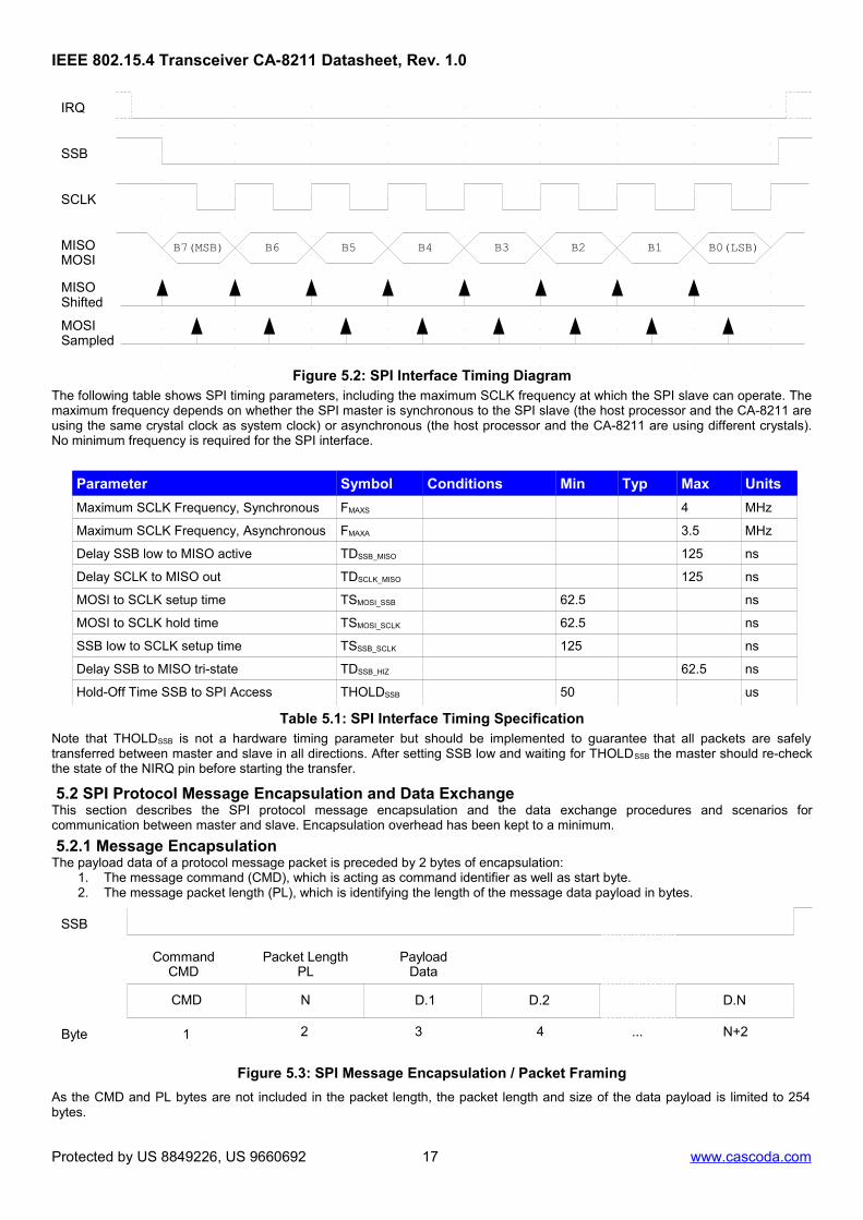
Figure 5.1: Interface Connections between Host and CA-8211The specification for serial clock polarity and phase has been aligned to fit several commonly-used low-power microcontrollerfamilies. The Clock Phase (SCKPH) should be set to 0, and SPI data is centred on the first edge of the serial clock (received dataon MOSI is captured on the first clock edge and transmitted data on MISO is shifted out on the following edge). The clock polarity(SCKPL) should be set to 1, and the serial clock is expected to be high when in inactive state. Note that for some microcontrollerfamilies the terminology can differ.
The polarity of the GPIO interrupt from the slave to the host is by default active low. It is active when the slave is able to receivedata, and inactive when the slave is busy and cannot accept an SPI transfer. When the slave has data to send to the master, it willcreate a falling edge (by deasserting then reasserting if necessary), at which point the master should begin a SPI transfer.
Protected by US 8849226, US 9660692 16 www.cascoda.com
Figure 5.2: SPI Interface Timing DiagramThe following table shows SPI timing parameters, including the maximum SCLK frequency at which the SPI slave can operate. Themaximum frequency depends on whether the SPI master is synchronous to the SPI slave (the host processor and the CA-8211 areusing the same crystal clock as system clock) or asynchronous (the host processor and the CA-8211 are using different crystals).No minimum frequency is required for the SPI interface.
Parameter Symbol Conditions Min Typ Max Units
Maximum SCLK Frequency, Synchronous FMAXS 4 MHz
Maximum SCLK Frequency, Asynchronous FMAXA 3.5 MHz
Delay SSB low to MISO active TDSSB_MISO 125 ns
Delay SCLK to MISO out TDSCLK_MISO 125 ns
MOSI to SCLK setup time TSMOSI_SSB 62.5 ns
MOSI to SCLK hold time TSMOSI_SCLK 62.5 ns
SSB low to SCLK setup time TSSSB_SCLK 125 ns
Delay SSB to MISO tri-state TDSSB_HIZ 62.5 ns
Hold-Off Time SSB to SPI Access THOLDSSB 50 us
Table 5.1: SPI Interface Timing SpecificationNote that THOLDSSB is not a hardware timing parameter but should be implemented to guarantee that all packets are safelytransferred between master and slave in all directions. After setting SSB low and waiting for THOLDSSB the master should re-checkthe state of the NIRQ pin before starting the transfer.
5.2 SPI Protocol Message Encapsulation and Data ExchangeThis section describes the SPI protocol message encapsulation and the data exchange procedures and scenarios forcommunication between master and slave. Encapsulation overhead has been kept to a minimum.
5.2.1 Message EncapsulationThe payload data of a protocol message packet is preceded by 2 bytes of encapsulation:
1. The message command (CMD), which is acting as command identifier as well as start byte.2. The message packet length (PL), which is identifying the length of the message data payload in bytes.
5.2.2 Data Exchange between Master and SlaveIn order to ensure robust 2-way communication, an IDLE message byte (FFH) has been added which is being sent when nomessage is available from the slave (CA-8211) or the master. This is used in combination with the NIRQ pin which signals to themaster if the slave is busy processing data, has a packet ready for the master to fetch and/or is able to receive messages from themaster. Cascoda has developed SPI drivers for the master function for a range of stand-alone microcontrollers as well as the Linuxoperating system. These are integrated in the Cascoda API driver software available on the Cascoda GitHub repository. Pleasecontact Cascoda for further details.If the NIRQ pin is high ('slave is busy'), the master has to back off and wait for NIRQ to go low until it sets SSB low and startstransmitting a data packet on MOSI. The NIRQ pin will be low until the transfer of the packet has been completed. If the CA-8211(slave) has a packet ready to send to the master, it signals this by a falling edge (high to low transition) on NIRQ which should beused to trigger an interrupt on the microcontroller hosting the SPI master code. MOSI should be set to IDLE if the master has nodata to send. Note that a falling edge on NIRQ does not necessarily indicate that the slave has data to send, it can also be atransition from busy state to idle state in the slave. The master should instigate a data read but discard the data if the receivedcommand is IDLE.Data transfer can be bi-directional, therefore the master should check each time there is a transfer if there is a valid API packet init's receive buffer. If the command byte is IDLE, the data can be discarded. For bi-directional transfer the message packets areunlikely to have the same length, and the master has to make sure that the SPI is enabled for the longer message to be completelytransferred (maximum of PL1 and PL2). Bytes sent after the payload of the shorter message are ignored.
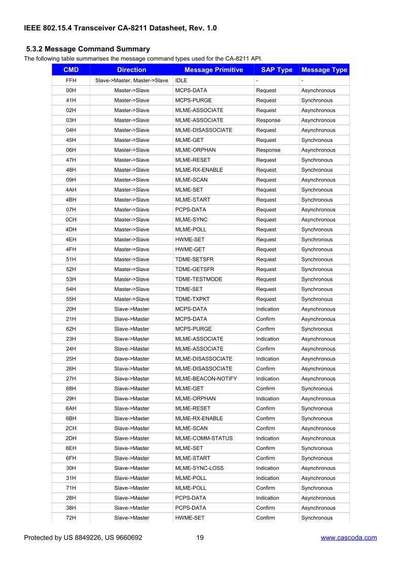
5.3 Message Command Definitions
5.3.1 Message ExchangeThe commands for the MAC layer MCPS-SAP and MLME-SAP are based on the service primitives as defined in section 7.1, “MACsublayer service specification”, of the IEEE 802.15.4-2006 standard. The PCPS commands are described in section 5.4.4 . TheHWME commands and primitives are further described in sections 5.4.5 and 5.4.6, and the TDME commands and primitives insections 5.4.7 and 5.4.8.
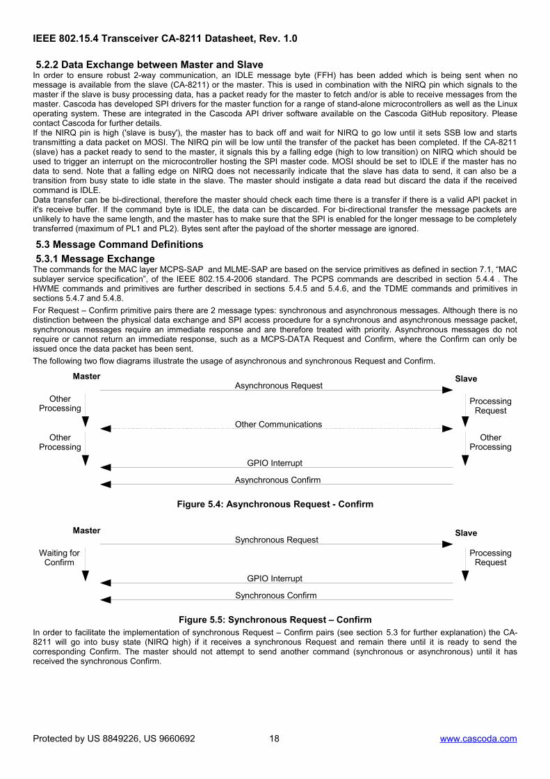
For Request – Confirm primitive pairs there are 2 message types: synchronous and asynchronous messages. Although there is nodistinction between the physical data exchange and SPI access procedure for a synchronous and asynchronous message packet,synchronous messages require an immediate response and are therefore treated with priority. Asynchronous messages do notrequire or cannot return an immediate response, such as a MCPS-DATA Request and Confirm, where the Confirm can only beissued once the data packet has been sent.
The following two flow diagrams illustrate the usage of asynchronous and synchronous Request and Confirm.
Figure 5.4: Asynchronous Request - Confirm
Figure 5.5: Synchronous Request – ConfirmIn order to facilitate the implementation of synchronous Request – Confirm pairs (see section 5.3 for further explanation) the CA-8211 will go into busy state (NIRQ high) if it receives a synchronous Request and remain there until it is ready to send thecorresponding Confirm. The master should not attempt to send another command (synchronous or asynchronous) until it hasreceived the synchronous Confirm.
Protected by US 8849226, US 9660692 18 www.cascoda.com
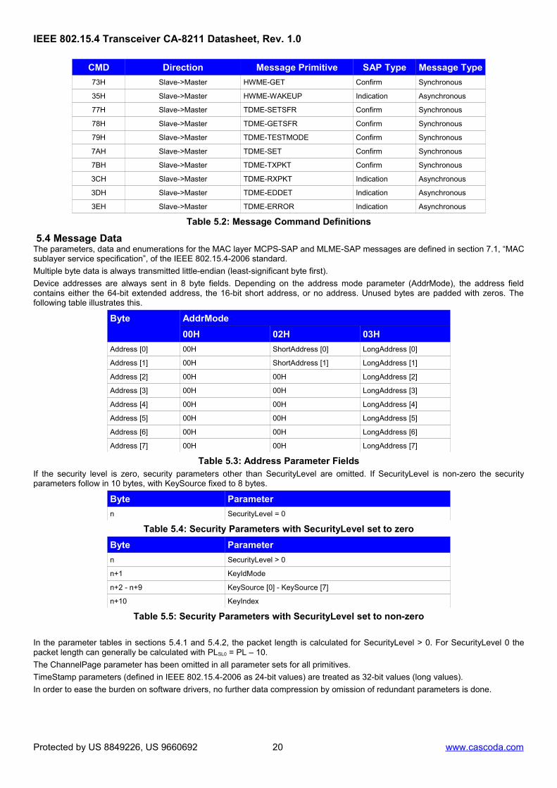
5.4 Message DataThe parameters, data and enumerations for the MAC layer MCPS-SAP and MLME-SAP messages are defined in section 7.1, “MACsublayer service specification”, of the IEEE 802.15.4-2006 standard.
Multiple byte data is always transmitted little-endian (least-significant byte first).
Device addresses are always sent in 8 byte fields. Depending on the address mode parameter (AddrMode), the address fieldcontains either the 64-bit extended address, the 16-bit short address, or no address. Unused bytes are padded with zeros. Thefollowing table illustrates this.
Byte AddrMode
00H 02H 03H
Address [0] 00H ShortAddress [0] LongAddress [0]
Address [1] 00H ShortAddress [1] LongAddress [1]
Address [2] 00H 00H LongAddress [2]
Address [3] 00H 00H LongAddress [3]
Address [4] 00H 00H LongAddress [4]
Address [5] 00H 00H LongAddress [5]
Address [6] 00H 00H LongAddress [6]
Address [7] 00H 00H LongAddress [7]
Table 5.3: Address Parameter FieldsIf the security level is zero, security parameters other than SecurityLevel are omitted. If SecurityLevel is non-zero the securityparameters follow in 10 bytes, with KeySource fixed to 8 bytes.
Byte Parameter
n SecurityLevel = 0
Table 5.4: Security Parameters with SecurityLevel set to zero
Byte Parameter
n SecurityLevel > 0
n+1 KeyIdMode
n+2 - n+9 KeySource [0] - KeySource [7]
n+10 KeyIndex
Table 5.5: Security Parameters with SecurityLevel set to non-zero
In the parameter tables in sections 5.4.1 and 5.4.2, the packet length is calculated for SecurityLevel > 0. For SecurityLevel 0 thepacket length can generally be calculated with PLSL0 = PL – 10.
The ChannelPage parameter has been omitted in all parameter sets for all primitives.
TimeStamp parameters (defined in IEEE 802.15.4-2006 as 24-bit values) are treated as 32-bit values (long values).
In order to ease the burden on software drivers, no further data compression by omission of redundant parameters is done.
Protected by US 8849226, US 9660692 20 www.cascoda.com
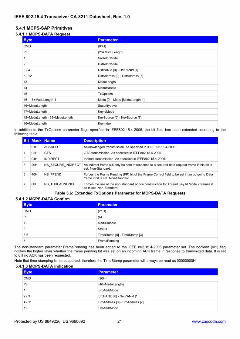
In addition to the TxOptions parameter flags specified in IEEE802.15.4-2006, the bit field has been extended according to thefollowing table:
Bit Mask Name Description
0 01H ACKREQ Acknowledged transmission. As specified in IEEE802.15.4-2006.
1 02H GTS GTS transmission. As specified in IEEE802.15.4-2006.
2 04H INDIRECT Indirect transmission. As specified in IEEE802.15.4-2006.
5 20H NS_SECURE_INDIRECT An indirect frame will only be sent in response to a secured data request frame if this bit is set. Non-Standard.
6 40H NS_FPEND Forces the Frame Pending (FP) bit of the Frame Control field to be set in an outgoing Data frame if bit is set. Non-Standard.
7 80H NS_THREADNONCE Forces the use of the non-standard nonce construction for Thread Key Id Mode 2 frames if bit is set. Non-Standard.
Table 5.6: Extended TxOptions Parameter for MCPS-DATA Requests
5.4.1.2 MCPS-DATA Confirm
Byte Parameter
CMD (21H)
PL (6)
1 MsduHandle
2 Status
3-6 TimeStamp [0] - TimeStamp [3]
7 FramePending
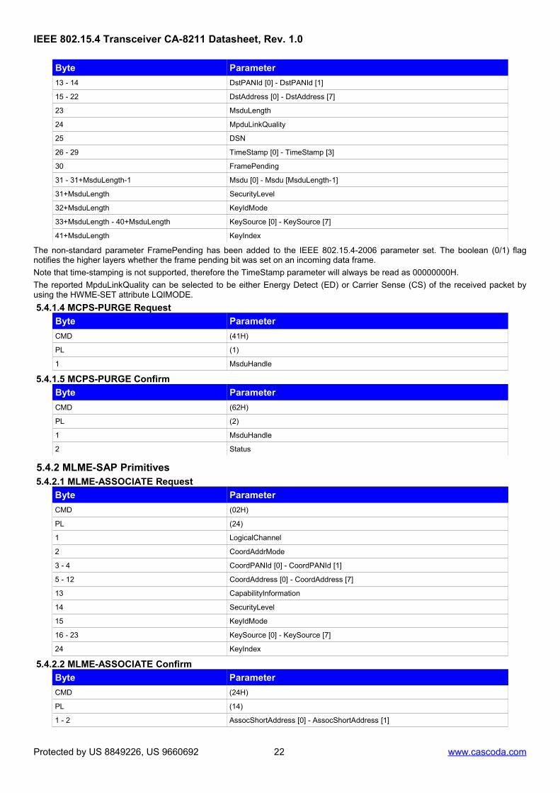
The non-standard parameter FramePending has been added to the IEEE 802.15.4-2006 parameter set. The boolean (0/1) flagnotifies the higher layer whether the frame pending bit was set on an incoming ACK frame in response to transmitted data. It is setto 0 if no ACK has been requested.
Note that time-stamping is not supported, therefore the TimeStamp parameter will always be read as 00000000H.
5.4.1.3 MCPS-DATA Indication
Byte Parameter
CMD (20H)
PL (40+MsduLength)
1 SrcAddrMode
2 - 3 SrcPANId [0] - SrcPANId [1]
4 - 11 SrcAddress [0] - SrcAddress [7]
12 DstAddrMode
Protected by US 8849226, US 9660692 21 www.cascoda.com
The non-standard parameter FramePending has been added to the IEEE 802.15.4-2006 parameter set. The boolean (0/1) flagnotifies the higher layers whether the frame pending bit was set on an incoming data frame.
Note that time-stamping is not supported, therefore the TimeStamp parameter will always be read as 00000000H.
The reported MpduLinkQuality can be selected to be either Energy Detect (ED) or Carrier Sense (CS) of the received packet byusing the HWME-SET attribute LQIMODE.
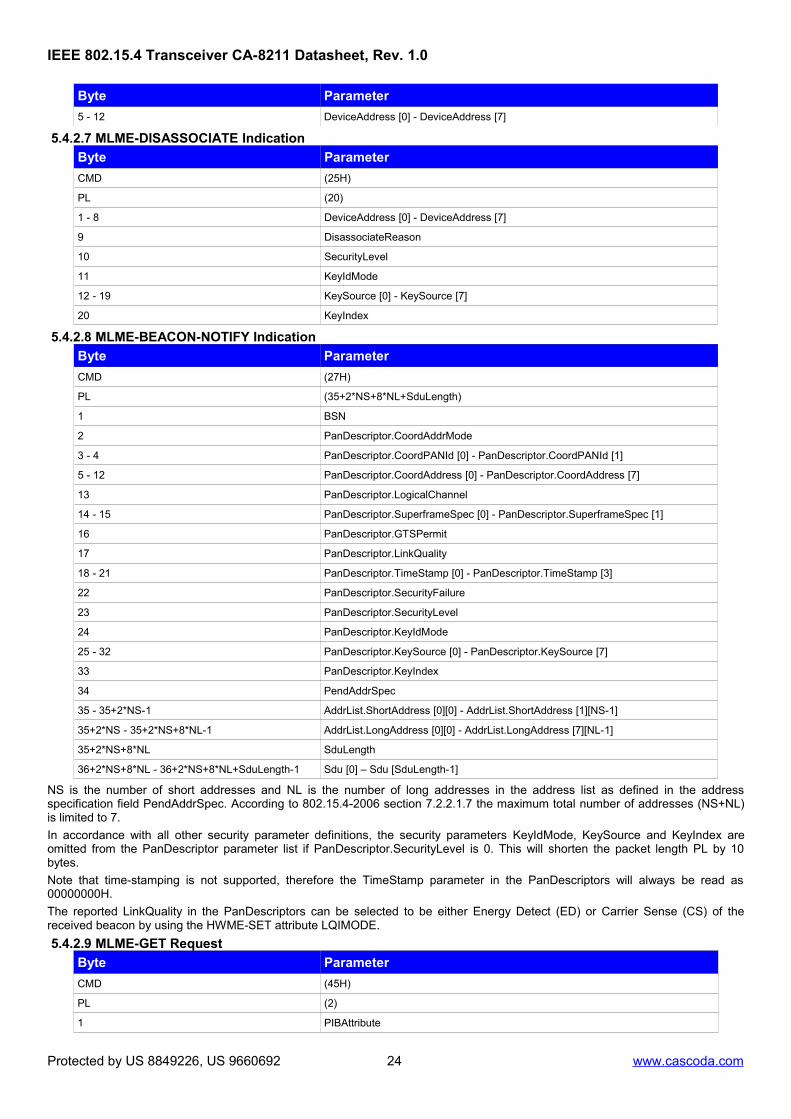
NS is the number of short addresses and NL is the number of long addresses in the address list as defined in the addressspecification field PendAddrSpec. According to 802.15.4-2006 section 7.2.2.1.7 the maximum total number of addresses (NS+NL)is limited to 7.
In accordance with all other security parameter definitions, the security parameters KeyIdMode, KeySource and KeyIndex areomitted from the PanDescriptor parameter list if PanDescriptor.SecurityLevel is 0. This will shorten the packet length PL by 10bytes.
Note that time-stamping is not supported, therefore the TimeStamp parameter in the PanDescriptors will always be read as00000000H.
The reported LinkQuality in the PanDescriptors can be selected to be either Energy Detect (ED) or Carrier Sense (CS) of thereceived beacon by using the HWME-SET attribute LQIMODE.
5.4.2.9 MLME-GET Request
Byte Parameter
CMD (45H)
PL (2)
1 PIBAttribute
Protected by US 8849226, US 9660692 24 www.cascoda.com
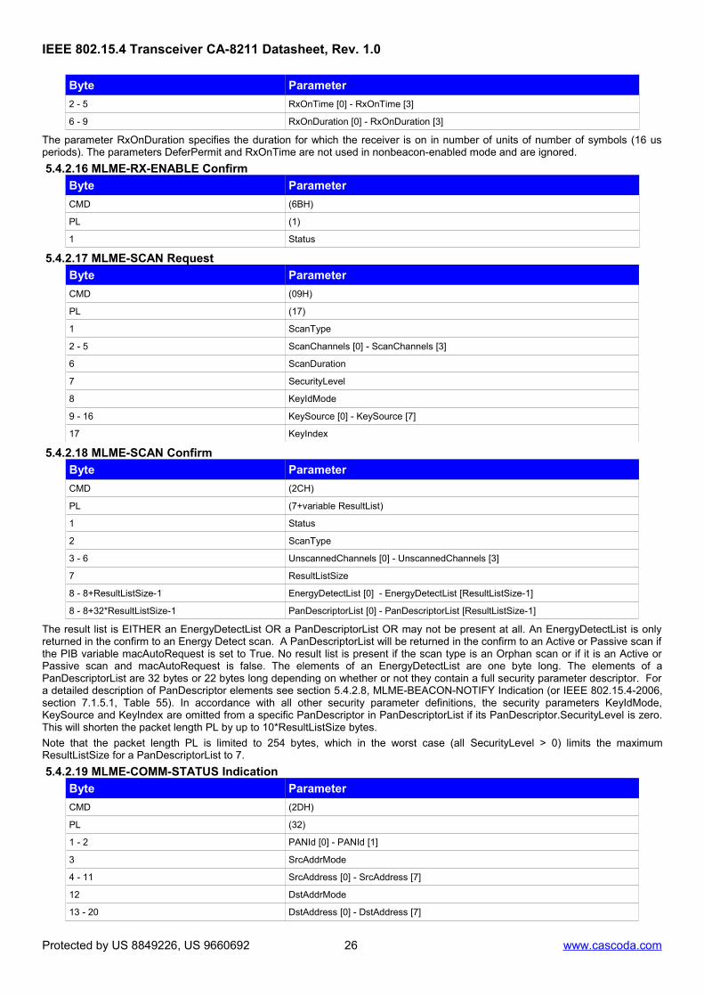
The parameter RxOnDuration specifies the duration for which the receiver is on in number of units of number of symbols (16 usperiods). The parameters DeferPermit and RxOnTime are not used in nonbeacon-enabled mode and are ignored.
The result list is EITHER an EnergyDetectList OR a PanDescriptorList OR may not be present at all. An EnergyDetectList is onlyreturned in the confirm to an Energy Detect scan. A PanDescriptorList will be returned in the confirm to an Active or Passive scan ifthe PIB variable macAutoRequest is set to True. No result list is present if the scan type is an Orphan scan or if it is an Active orPassive scan and macAutoRequest is false. The elements of an EnergyDetectList are one byte long. The elements of aPanDescriptorList are 32 bytes or 22 bytes long depending on whether or not they contain a full security parameter descriptor. Fora detailed description of PanDescriptor elements see section 5.4.2.8, MLME-BEACON-NOTIFY Indication (or IEEE 802.15.4-2006,section 7.1.5.1, Table 55). In accordance with all other security parameter definitions, the security parameters KeyIdMode,KeySource and KeyIndex are omitted from a specific PanDescriptor in PanDescriptorList if its PanDescriptor.SecurityLevel is zero.This will shorten the packet length PL by up to 10*ResultListSize bytes.
Note that the packet length PL is limited to 254 bytes, which in the worst case (all SecurityLevel > 0) limits the maximumResultListSize for a PanDescriptorList to 7.
5.4.2.19 MLME-COMM-STATUS Indication
Byte Parameter
CMD (2DH)
PL (32)
1 - 2 PANId [0] - PANId [1]
3 SrcAddrMode
4 - 11 SrcAddress [0] - SrcAddress [7]
12 DstAddrMode
13 - 20 DstAddress [0] - DstAddress [7]
Protected by US 8849226, US 9660692 26 www.cascoda.com
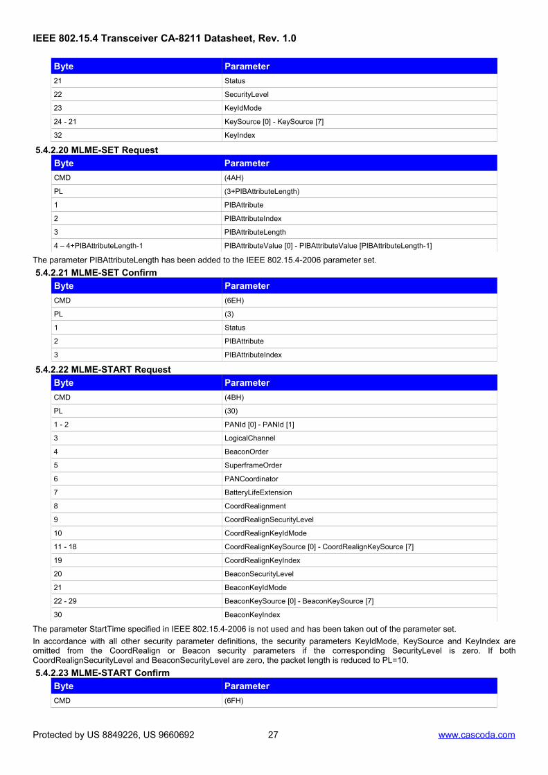
The parameter StartTime specified in IEEE 802.15.4-2006 is not used and has been taken out of the parameter set.
In accordance with all other security parameter definitions, the security parameters KeyIdMode, KeySource and KeyIndex areomitted from the CoordRealign or Beacon security parameters if the corresponding SecurityLevel is zero. If bothCoordRealignSecurityLevel and BeaconSecurityLevel are zero, the packet length is reduced to PL=10.
5.4.2.23 MLME-START Confirm
Byte Parameter
CMD (6FH)
Protected by US 8849226, US 9660692 27 www.cascoda.com
5.4.2.24 MLME-SYNC RequestThis command is not featured in this version because it is only used in Beacon mode which has not been implemented.
5.4.2.25 MLME-SYNC-LOSS Indication
Byte Parameter
CMD (30H)
PL (15)
1 LossReason
2 - 3 PANId [0] - PANId [1]
4 LogicalChannel
5 SecurityLevel
6 KeyIdMode
7 - 14 KeySource [0] - KeySource [7]
15 KeyIndex
5.4.2.26 MLME-POLL Request
Byte Parameter
CMD (4DH)
PL (24)
1 CoordAddressMode
2 - 3 CoordinatorPANId [0] - CoordinatorPANId [1]
4 - 11 CoordAddress [0] - CoordAddress [7]
12 SecurityLevel
13 KeyIdMode
14 - 21 KeySource [0] - KeySource [7]
22 KeyIndex
5.4.2.27 MLME-POLL Confirm
Byte Parameter
CMD (71H)
PL (1)
1 Status
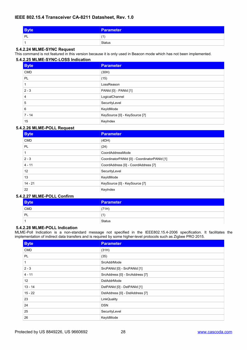
5.4.2.28 MLME-POLL IndicationMLME-Poll Indication is a non-standard message not specified in the IEEE802.15.4-2006 specification. It facilitates theimplementation of indirect data transfers and is required by some higher-level protocols such as Zigbee PRO 2015.
Byte Parameter
CMD (31H)
PL (35)
1 SrcAddrMode
2 - 3 SrcPANId [0] - SrcPANId [1]
4 - 11 SrcAddress [0] - SrcAddress [7]
12 DstAddrMode
13 - 14 DstPANId [0] - DstPANId [1]
15 - 22 DstAddress [0] - DstAddress [7]
23 LinkQuality
24 DSN
25 SecurityLevel
26 KeyIdMode
Protected by US 8849226, US 9660692 28 www.cascoda.com
The usage of MLME-POLL Indications can be configured via the HWME attribute POLLINGMODE (see 5.4.6.2 ). The attributedetermines when poll indications are issued by the MAC layer (not issued, always issued or only if there is no data sent). A MLME-POLL Indication will be issued when a data request command frame has been received by the device.
The reported LinkQuality can be selected to be either Energy Detect (ED) or Carrier Sense (CS) of the received packet by using theHWME-SET attribute LQIMODE.
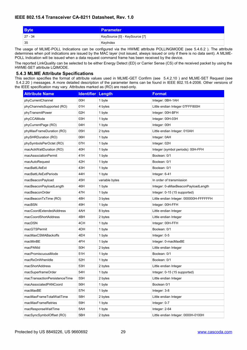
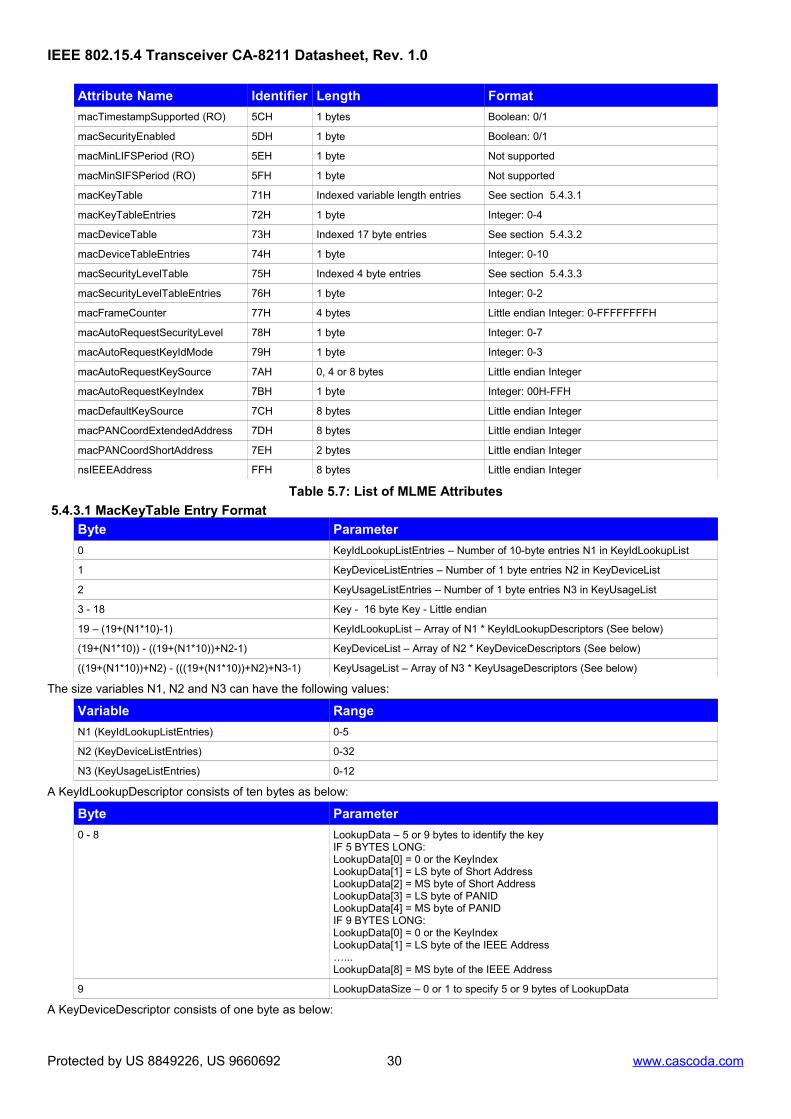
5.4.3 MLME Attribute SpecificationsThis section specifies the format of attribute values used in MLME-GET Confirm (see 5.4.2.10 ) and MLME-SET Request (see 5.4.2.20 ) messages. A more detailed description of the parameter items can be found in IEEE 802.15.4-2006. Other versions ofthe IEEE specification may vary. Attributes marked as (RO) are read-only.
Attribute Name Identifier Length Format
phyCurrentChannel 00H 1 byte Integer: 0BH-1AH
phyChannelsSupported (RO) 01H 4 bytes Little endian Integer 07FFF800H
phyTransmitPower 02H 1 byte Integer: 00H-BFH
phyCCAMode 03H 1 byte Integer: 00H-03H
phyCurrentPage (RO) 04H 1 byte Integer: 00H
phyMaxFrameDuration (RO) 05H 2 bytes Little endian Integer: 010AH
macDefaultKeySource 7CH 8 bytes Little endian Integer
macPANCoordExtendedAddress 7DH 8 bytes Little endian Integer
macPANCoordShortAddress 7EH 2 bytes Little endian Integer
nsIEEEAddress FFH 8 bytes Little endian Integer
Table 5.7: List of MLME Attributes
5.4.3.1 MacKeyTable Entry Format
Byte Parameter
0 KeyIdLookupListEntries – Number of 10-byte entries N1 in KeyIdLookupList
1 KeyDeviceListEntries – Number of 1 byte entries N2 in KeyDeviceList
2 KeyUsageListEntries – Number of 1 byte entries N3 in KeyUsageList
3 - 18 Key - 16 byte Key - Little endian
19 – (19+(N1*10)-1) KeyIdLookupList – Array of N1 * KeyIdLookupDescriptors (See below)
(19+(N1*10)) - ((19+(N1*10))+N2-1) KeyDeviceList – Array of N2 * KeyDeviceDescriptors (See below)
((19+(N1*10))+N2) - (((19+(N1*10))+N2)+N3-1) KeyUsageList – Array of N3 * KeyUsageDescriptors (See below)
The size variables N1, N2 and N3 can have the following values:
Variable Range
N1 (KeyIdLookupListEntries) 0-5
N2 (KeyDeviceListEntries) 0-32
N3 (KeyUsageListEntries) 0-12
A KeyIdLookupDescriptor consists of ten bytes as below:
Byte Parameter
0 - 8 LookupData – 5 or 9 bytes to identify the keyIF 5 BYTES LONG:LookupData[0] = 0 or the KeyIndexLookupData[1] = LS byte of Short AddressLookupData[2] = MS byte of Short AddressLookupData[3] = LS byte of PANIDLookupData[4] = MS byte of PANIDIF 9 BYTES LONG:LookupData[0] = 0 or the KeyIndexLookupData[1] = LS byte of the IEEE Address…...LookupData[8] = MS byte of the IEEE Address
9 LookupDataSize – 0 or 1 to specify 5 or 9 bytes of LookupData
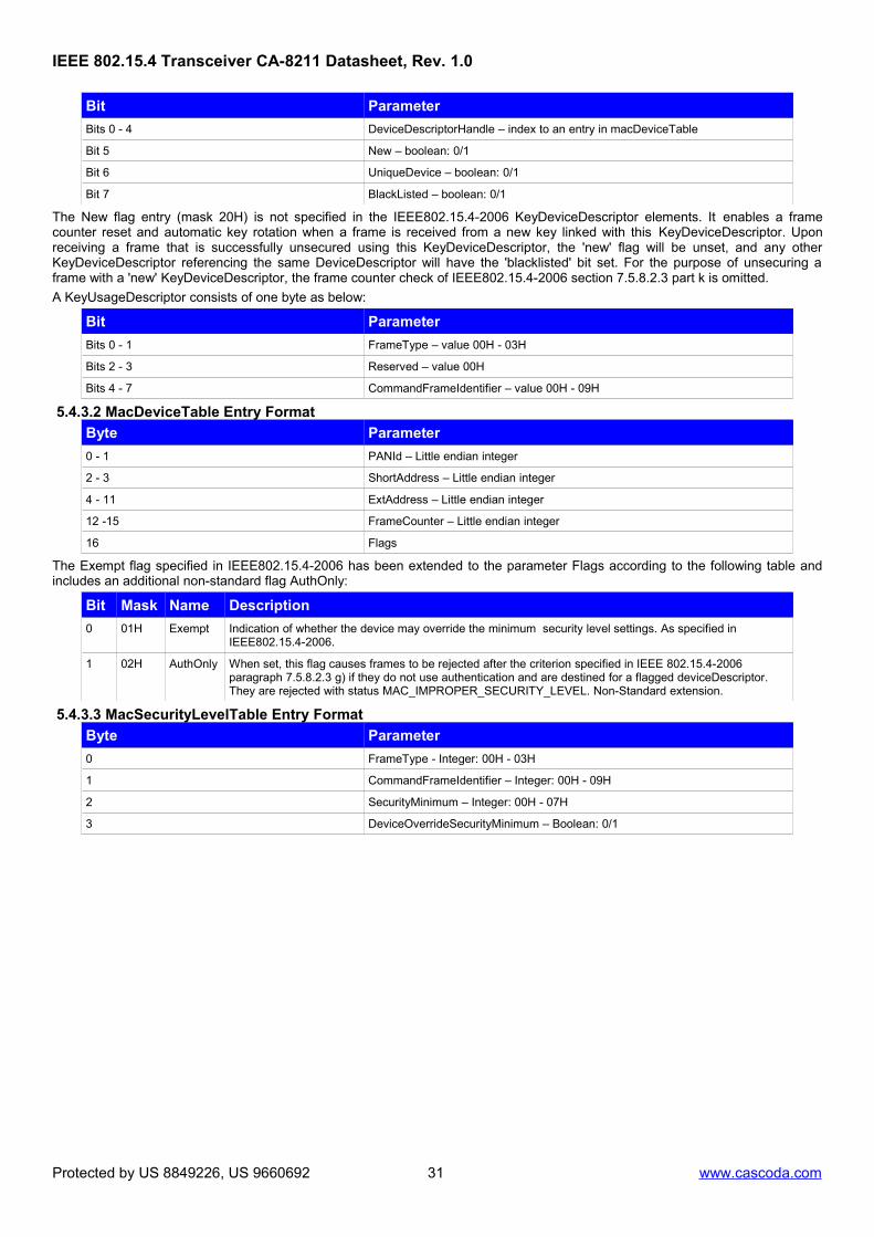
A KeyDeviceDescriptor consists of one byte as below:
Protected by US 8849226, US 9660692 30 www.cascoda.com
Bits 0 - 4 DeviceDescriptorHandle – index to an entry in macDeviceTable
Bit 5 New – boolean: 0/1
Bit 6 UniqueDevice – boolean: 0/1
Bit 7 BlackListed – boolean: 0/1
The New flag entry (mask 20H) is not specified in the IEEE802.15.4-2006 KeyDeviceDescriptor elements. It enables a framecounter reset and automatic key rotation when a frame is received from a new key linked with this KeyDeviceDescriptor. Uponreceiving a frame that is successfully unsecured using this KeyDeviceDescriptor, the 'new' flag will be unset, and any otherKeyDeviceDescriptor referencing the same DeviceDescriptor will have the 'blacklisted' bit set. For the purpose of unsecuring aframe with a 'new' KeyDeviceDescriptor, the frame counter check of IEEE802.15.4-2006 section 7.5.8.2.3 part k is omitted.
A KeyUsageDescriptor consists of one byte as below:
Bit Parameter
Bits 0 - 1 FrameType – value 00H - 03H
Bits 2 - 3 Reserved – value 00H
Bits 4 - 7 CommandFrameIdentifier – value 00H - 09H
5.4.3.2 MacDeviceTable Entry Format
Byte Parameter
0 - 1 PANId – Little endian integer
2 - 3 ShortAddress – Little endian integer
4 - 11 ExtAddress – Little endian integer
12 -15 FrameCounter – Little endian integer
16 Flags
The Exempt flag specified in IEEE802.15.4-2006 has been extended to the parameter Flags according to the following table andincludes an additional non-standard flag AuthOnly:
Bit Mask Name Description
0 01H Exempt Indication of whether the device may override the minimum security level settings. As specified in IEEE802.15.4-2006.
1 02H AuthOnly When set, this flag causes frames to be rejected after the criterion specified in IEEE 802.15.4-2006 paragraph 7.5.8.2.3 g) if they do not use authentication and are destined for a flagged deviceDescriptor. They are rejected with status MAC_IMPROPER_SECURITY_LEVEL. Non-Standard extension.
5.4.3.3 MacSecurityLevelTable Entry Format
Byte Parameter
0 FrameType - Integer: 00H - 03H
1 CommandFrameIdentifier – Integer: 00H - 09H
2 SecurityMinimum – Integer: 00H - 07H
3 DeviceOverrideSecurityMinimum – Boolean: 0/1
Protected by US 8849226, US 9660692 31 www.cascoda.com
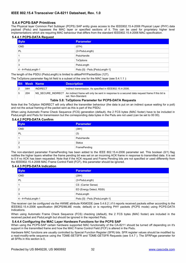
5.4.4 PCPS-SAP PrimitivesThe Physical layer Common Part Sublayer (PCPS) SAP entity gives access to the IEEE802.15.4-2006 Physical Layer (PHY) datapayload (Psdu) and bypasses the MAC layer or specified sections of it. This can be used for proprietary higher levelimplementations which are requiring MAC behaviour that differs from the standard IEEE802.15.4-2006 MAC specification.
5.4.4.1 PCPS-DATA Request
Byte Parameter
CMD (07H)
PL (3+PsduLength)
1 PsduHandle
2 TxOptions
3 PsduLength
4 - 4+PsduLength-1 Psdu [0] - Psdu [PsduLength-1]
The length of the PSDU (PsduLength) is limited to aMaxPHYPacketSize (127).
The TxOptions parameter flag bit field is a subset of the one for the MAC layer (see 5.4.1.1 ):
Bit Mask Name Description
2 04H INDIRECT Indirect transmission. As specified in IEEE802.15.4-2006.
5 20H NS_SECURE_INDIRECT An indirect frame will only be sent in response to a secured data request frame if this bit is set. Non-Standard.
Table 5.8: TxOptions Parameter for PCPS-DATA RequestsNote that the TxOption INDIRECT will only affect the transmitter behaviour (the data is put on an indirect queue waiting for a poll)and not the actual framing of the packet sent as this is part of the PSDU.
When using Automatic Frame Check Sequence (FCS) generation (default), the 2 FCS bytes (MAC footer) have to be included inPsduLength and Psdu for transmission but the corresponding data bytes in the Psdu are not used (can be set to 00 00).
5.4.4.2 PCPS-DATA Confirm
Byte Parameter
CMD (38H)
PL (3)
1 PsduHandle
2 Status
3 FramePending
The non-standard parameter FramePending has been added to the IEEE 802.15.4-2006 parameter set. This boolean (0/1) flagnotifies the higher layers whether the frame pending bit was set on an incoming ACK frame in response to transmitted data. It is setto 0 if no ACK has been requested. Note that if the ACK request and Frame Pending bits are not specified or used differently fromthe IEEE802.15.4-2006 MAC Frame Control Field (FCF), this parameter should be ignored.
5.4.4.3 PCPS-DATA Indication
Byte Parameter
CMD (28H)
PL (3+PsduLength)
1 CS (Carrier Sense)
2 ED (Energy Detect, RSSI)
3 PsduLength
4 - 4+PsduLength-1 Psdu [0] - Psdu [PsduLength-1]
The receiver can be configured via the HWME attribute RXMODE (see 5.4.6.2 ) if it reports received packets either according to theIEEE802.15.4-2006 specification (MCPS/MLME mode, default) or is reporting PHY packets (PCPS mode) using PCPS-DATAIndications.
When using Automatic Frame Check Sequence (FCS) checking (default), the 2 FCS bytes (MAC footer) are included in thereceived packet and PsduLength but should be ignored in the reported Psdu.
5.4.4.4 Configuring the MAC Layer Hardware Functions for the PCPS SAPWhen using the PCPS-SAP certain hardware supported MAC functionality of the CA-8211 should be turned off depending on it'ssupport in the transmitted frame and how the MAC Frame Control Field (FCF) is altered in the Psdu.
Hardware MAC functions are usually controlled by Special Function Register (SFR) bits. SFR register values should be modified bya read-modify-write sequence using the TDME-SETSFR and TDME-GETSFR Requests (see 5.4.7 ). The SFRPage parameter forall SFRs in this section is 0,
Protected by US 8849226, US 9660692 32 www.cascoda.com
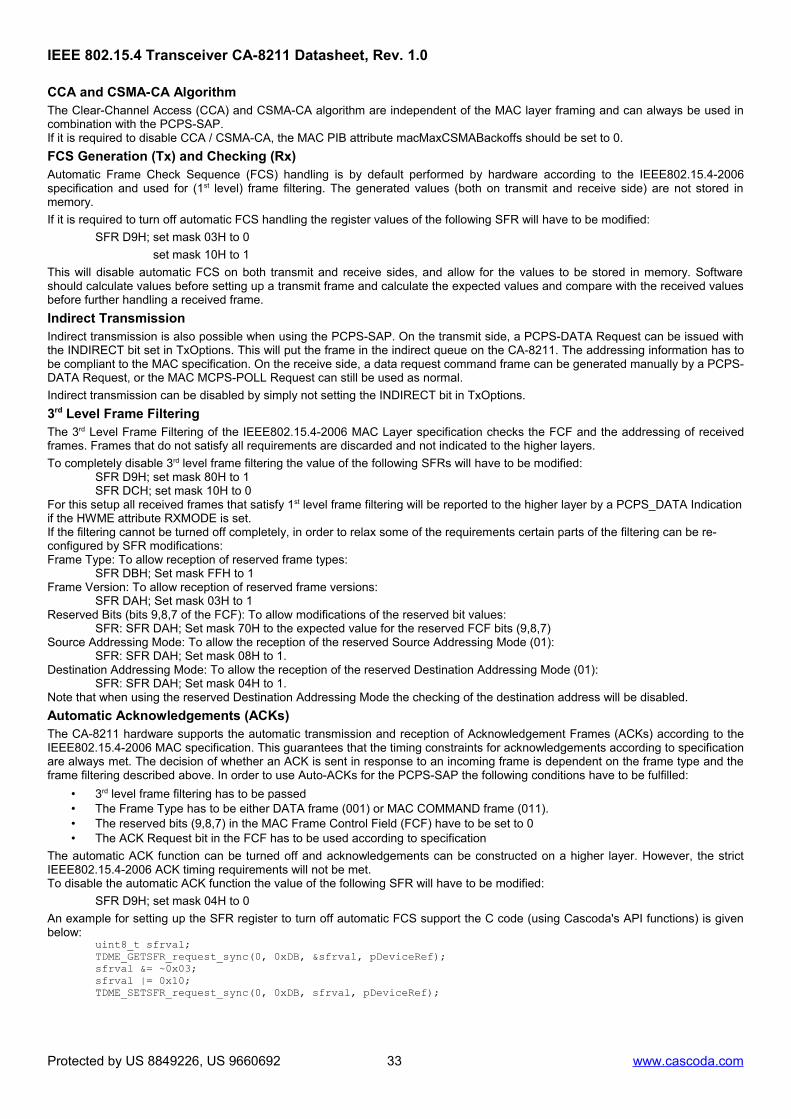
CCA and CSMA-CA AlgorithmThe Clear-Channel Access (CCA) and CSMA-CA algorithm are independent of the MAC layer framing and can always be used incombination with the PCPS-SAP.If it is required to disable CCA / CSMA-CA, the MAC PIB attribute macMaxCSMABackoffs should be set to 0.
FCS Generation (Tx) and Checking (Rx)Automatic Frame Check Sequence (FCS) handling is by default performed by hardware according to the IEEE802.15.4-2006specification and used for (1st level) frame filtering. The generated values (both on transmit and receive side) are not stored inmemory.
If it is required to turn off automatic FCS handling the register values of the following SFR will have to be modified:
SFR D9H; set mask 03H to 0
set mask 10H to 1
This will disable automatic FCS on both transmit and receive sides, and allow for the values to be stored in memory. Softwareshould calculate values before setting up a transmit frame and calculate the expected values and compare with the received valuesbefore further handling a received frame.
Indirect TransmissionIndirect transmission is also possible when using the PCPS-SAP. On the transmit side, a PCPS-DATA Request can be issued withthe INDIRECT bit set in TxOptions. This will put the frame in the indirect queue on the CA-8211. The addressing information has tobe compliant to the MAC specification. On the receive side, a data request command frame can be generated manually by a PCPS-DATA Request, or the MAC MCPS-POLL Request can still be used as normal.
Indirect transmission can be disabled by simply not setting the INDIRECT bit in TxOptions.
3rd Level Frame FilteringThe 3rd Level Frame Filtering of the IEEE802.15.4-2006 MAC Layer specification checks the FCF and the addressing of receivedframes. Frames that do not satisfy all requirements are discarded and not indicated to the higher layers.
To completely disable 3rd level frame filtering the value of the following SFRs will have to be modified:SFR D9H; set mask 80H to 1SFR DCH; set mask 10H to 0
For this setup all received frames that satisfy 1st level frame filtering will be reported to the higher layer by a PCPS_DATA Indicationif the HWME attribute RXMODE is set.If the filtering cannot be turned off completely, in order to relax some of the requirements certain parts of the filtering can be re-configured by SFR modifications:Frame Type: To allow reception of reserved frame types:
SFR DBH; Set mask FFH to 1Frame Version: To allow reception of reserved frame versions:
SFR DAH; Set mask 03H to 1Reserved Bits (bits 9,8,7 of the FCF): To allow modifications of the reserved bit values:
SFR: SFR DAH; Set mask 70H to the expected value for the reserved FCF bits (9,8,7)Source Addressing Mode: To allow the reception of the reserved Source Addressing Mode (01):
SFR: SFR DAH; Set mask 08H to 1.Destination Addressing Mode: To allow the reception of the reserved Destination Addressing Mode (01):
SFR: SFR DAH; Set mask 04H to 1.Note that when using the reserved Destination Addressing Mode the checking of the destination address will be disabled.
Automatic Acknowledgements (ACKs)The CA-8211 hardware supports the automatic transmission and reception of Acknowledgement Frames (ACKs) according to theIEEE802.15.4-2006 MAC specification. This guarantees that the timing constraints for acknowledgements according to specificationare always met. The decision of whether an ACK is sent in response to an incoming frame is dependent on the frame type and theframe filtering described above. In order to use Auto-ACKs for the PCPS-SAP the following conditions have to be fulfilled:
• 3rd level frame filtering has to be passed• The Frame Type has to be either DATA frame (001) or MAC COMMAND frame (011).• The reserved bits (9,8,7) in the MAC Frame Control Field (FCF) have to be set to 0• The ACK Request bit in the FCF has to be used according to specification
The automatic ACK function can be turned off and acknowledgements can be constructed on a higher layer. However, the strictIEEE802.15.4-2006 ACK timing requirements will not be met.To disable the automatic ACK function the value of the following SFR will have to be modified:
SFR D9H; set mask 04H to 0
An example for setting up the SFR register to turn off automatic FCS support the C code (using Cascoda's API functions) is givenbelow:
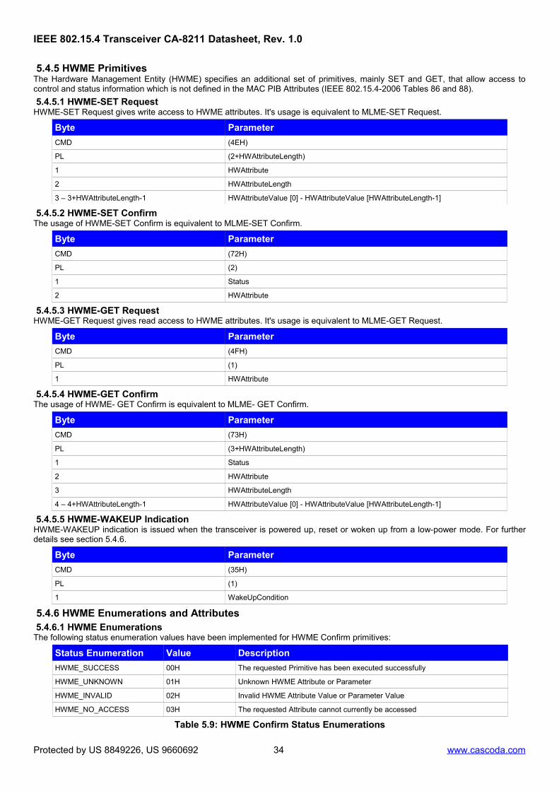
5.4.5 HWME PrimitivesThe Hardware Management Entity (HWME) specifies an additional set of primitives, mainly SET and GET, that allow access tocontrol and status information which is not defined in the MAC PIB Attributes (IEEE 802.15.4-2006 Tables 86 and 88).
5.4.5.1 HWME-SET RequestHWME-SET Request gives write access to HWME attributes. It's usage is equivalent to MLME-SET Request.
5.4.5.5 HWME-WAKEUP IndicationHWME-WAKEUP indication is issued when the transceiver is powered up, reset or woken up from a low-power mode. For furtherdetails see section 5.4.6.
Byte Parameter
CMD (35H)
PL (1)
1 WakeUpCondition
5.4.6 HWME Enumerations and Attributes 5.4.6.1 HWME EnumerationsThe following status enumeration values have been implemented for HWME Confirm primitives:
Status Enumeration Value Description
HWME_SUCCESS 00H The requested Primitive has been executed successfully
HWME_UNKNOWN 01H Unknown HWME Attribute or Parameter
HWME_INVALID 02H Invalid HWME Attribute Value or Parameter Value
HWME_NO_ACCESS 03H The requested Attribute cannot currently be accessed
Table 5.9: HWME Confirm Status Enumerations
Protected by US 8849226, US 9660692 34 www.cascoda.com
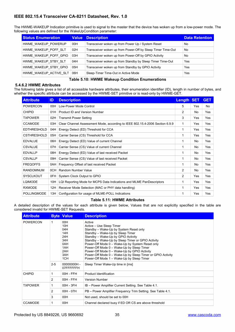
The HWME-WAKEUP Indication primitive is used to signal to the master that the device has woken up from a low-power mode. Thefollowing values are defined for the WakeUpCondition parameter:
Status Enumeration Value Description Data Retention
HWME_WAKEUP_POWERUP 00H Transceiver woken up from Power Up / System Reset No
HWME_WAKEUP_POFF_SLT 02H Transceiver woken up from Power-Off by Sleep Timer Time-Out No
HWME_WAKEUP_POFF_GPIO 03H Transceiver woken up from Power-Off by GPIO Activity No
HWME_WAKEUP_STBY_SLT 04H Transceiver woken up from Standby by Sleep Timer Time-Out Yes
HWME_WAKEUP_STBY_GPIO 05H Transceiver woken up from Standby by GPIO Activity Yes
HWME_WAKEUP_ACTIVE_SLT 06H Sleep-Timer Time-Out in Active Mode Yes
Table 5.10: HWME Wakeup Condition Enumerations
5.4.6.2 HWME AttributesThe following table gives a list of all accessible hardware attributes, their enumeration identifier (ID), length in number of bytes, andwhether the specific attribute can be accessed by the HWME-SET primitive or is read-only by HWME-GET.
Attribute ID Description Length SET GET
POWERCON 00H Low-Power Mode Control 5 Yes No
CHIPID 01H Product ID and Version Number 2 No Yes
TXPOWER 02H Transmit Power Setting 3 Yes Yes
CCAMODE 03H Clear Channel Assessment Mode, according to IEEE 802.15.4-2006 Section 6.9.9 1 Yes Yes
EDTHRESHOLD 04H Energy Detect (ED) Threshold for CCA 1 Yes Yes
CSTHRESHOLD 05H Carrier Sense (CS) Threshold for CCA 1 Yes Yes
EDVALUE 06H Energy Detect (ED) Value of current Channel 1 No Yes
CSVALUE 07H Carrier Sense (CS) Value of current Channel 1 No Yes
EDVALLP 08H Energy Detect (ED) Value of last received Packet 1 No Yes
CSVALLP 09H Carrier Sense (CS) Value of last received Packet 1 No Yes
FREQOFFS 0AH Frequency Offset of last received Packet 1 No Yes
RANDOMNUM 0CH Random Number Value 2 No Yes
SYSCLKOUT 0FH System Clock Output to GPIO 2 Yes Yes
LQIMODE 10H LQI Reporting Mode for MCPS Data Indications and MLME PanDescriptors 1 Yes Yes
RXMODE 12H Receiver Mode Selection (MAC or PHY data handling) 1 Yes Yes
POLLINGMODE 13H Configuration for usage of MLME-POLL Indications 1 Yes Yes
Table 5.11: HWME AttributesA detailed description of the values for each attribute is given below, Values that are not explicitly specified in the table areconsidered invalid for HWME-SET Requests.
Attribute Byte Value Description
POWERCON 1 00H10H04H14H24H34H0AH1AH2AH3AH1CH
ActiveActive – Use Sleep TimerStandby – Wake-Up by System Reset onlyStandby – Wake-Up by Sleep TimerStandby – Wake-Up by GPIO ActivityStandby – Wake-Up by Sleep Timer or GPIO ActivityPower-Off Mode 0 – Wake-Up by System Reset onlyPower-Off Mode 0 – Wake-Up by Sleep TimerPower-Off Mode 0 – Wake-Up by GPIO ActivityPower-Off Mode 0 – Wake-Up by Sleep Timer or GPIO ActivityPower-Off Mode 1 – Wake-Up by Sleep Timer
2-5 00000000H - 07FFFFFFH
Sleep Timer Wake-Up time in [ms]
CHIPID 1 00H - FFH Product Identification
2 00H - FFH Version Number
TXPOWER 1 00H - 3FH IB – Power Amplifier Current Setting. See Table 4.1.
2 00H - 07H PB – Power Amplifier Frequency Trim Setting. See Table 4.1.
3 00H Not used, should be set to 00H
CCAMODE 1 00H Channel declared busy if ED OR CS are above threshold
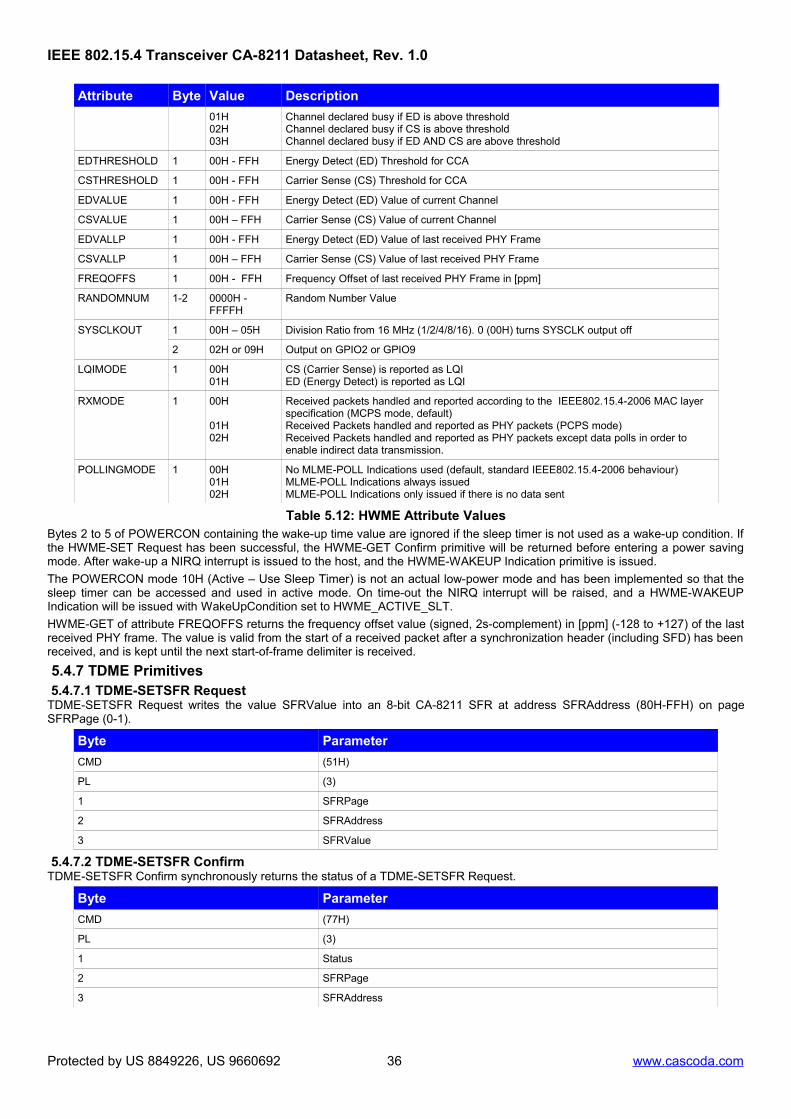
Protected by US 8849226, US 9660692 35 www.cascoda.com
Channel declared busy if ED is above thresholdChannel declared busy if CS is above thresholdChannel declared busy if ED AND CS are above threshold
EDTHRESHOLD 1 00H - FFH Energy Detect (ED) Threshold for CCA
CSTHRESHOLD 1 00H - FFH Carrier Sense (CS) Threshold for CCA
EDVALUE 1 00H - FFH Energy Detect (ED) Value of current Channel
CSVALUE 1 00H – FFH Carrier Sense (CS) Value of current Channel
EDVALLP 1 00H - FFH Energy Detect (ED) Value of last received PHY Frame
CSVALLP 1 00H – FFH Carrier Sense (CS) Value of last received PHY Frame
FREQOFFS 1 00H - FFH Frequency Offset of last received PHY Frame in [ppm]
RANDOMNUM 1-2 0000H - FFFFH
Random Number Value
SYSCLKOUT 1 00H – 05H Division Ratio from 16 MHz (1/2/4/8/16). 0 (00H) turns SYSCLK output off
2 02H or 09H Output on GPIO2 or GPIO9
LQIMODE 1 00H 01H
CS (Carrier Sense) is reported as LQIED (Energy Detect) is reported as LQI
RXMODE 1 00H
01H02H
Received packets handled and reported according to the IEEE802.15.4-2006 MAC layer specification (MCPS mode, default)Received Packets handled and reported as PHY packets (PCPS mode)Received Packets handled and reported as PHY packets except data polls in order to enable indirect data transmission.
POLLINGMODE 1 00H01H02H
No MLME-POLL Indications used (default, standard IEEE802.15.4-2006 behaviour)MLME-POLL Indications always issued MLME-POLL Indications only issued if there is no data sent
Table 5.12: HWME Attribute ValuesBytes 2 to 5 of POWERCON containing the wake-up time value are ignored if the sleep timer is not used as a wake-up condition. Ifthe HWME-SET Request has been successful, the HWME-GET Confirm primitive will be returned before entering a power savingmode. After wake-up a NIRQ interrupt is issued to the host, and the HWME-WAKEUP Indication primitive is issued.
The POWERCON mode 10H (Active – Use Sleep Timer) is not an actual low-power mode and has been implemented so that thesleep timer can be accessed and used in active mode. On time-out the NIRQ interrupt will be raised, and a HWME-WAKEUPIndication will be issued with WakeUpCondition set to HWME_ACTIVE_SLT.
HWME-GET of attribute FREQOFFS returns the frequency offset value (signed, 2s-complement) in [ppm] (-128 to +127) of the lastreceived PHY frame. The value is valid from the start of a received packet after a synchronization header (including SFD) has beenreceived, and is kept until the next start-of-frame delimiter is received.
5.4.7 TDME Primitives 5.4.7.1 TDME-SETSFR RequestTDME-SETSFR Request writes the value SFRValue into an 8-bit CA-8211 SFR at address SFRAddress (80H-FFH) on pageSFRPage (0-1).
Byte Parameter
CMD (51H)
PL (3)
1 SFRPage
2 SFRAddress
3 SFRValue
5.4.7.2 TDME-SETSFR ConfirmTDME-SETSFR Confirm synchronously returns the status of a TDME-SETSFR Request.
Byte Parameter
CMD (77H)
PL (3)
1 Status
2 SFRPage
3 SFRAddress
Protected by US 8849226, US 9660692 36 www.cascoda.com
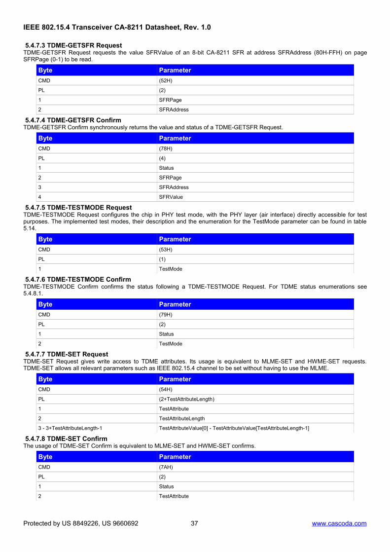
5.4.7.3 TDME-GETSFR RequestTDME-GETSFR Request requests the value SFRValue of an 8-bit CA-8211 SFR at address SFRAddress (80H-FFH) on pageSFRPage (0-1) to be read.
Byte Parameter
CMD (52H)
PL (2)
1 SFRPage
2 SFRAddress
5.4.7.4 TDME-GETSFR ConfirmTDME-GETSFR Confirm synchronously returns the value and status of a TDME-GETSFR Request.
Byte Parameter
CMD (78H)
PL (4)
1 Status
2 SFRPage
3 SFRAddress
4 SFRValue
5.4.7.5 TDME-TESTMODE RequestTDME-TESTMODE Request configures the chip in PHY test mode, with the PHY layer (air interface) directly accessible for testpurposes. The implemented test modes, their description and the enumeration for the TestMode parameter can be found in table5.14.
Byte Parameter
CMD (53H)
PL (1)
1 TestMode
5.4.7.6 TDME-TESTMODE ConfirmTDME-TESTMODE Confirm confirms the status following a TDME-TESTMODE Request. For TDME status enumerations see5.4.8.1.
Byte Parameter
CMD (79H)
PL (2)
1 Status
2 TestMode
5.4.7.7 TDME-SET RequestTDME-SET Request gives write access to TDME attributes. Its usage is equivalent to MLME-SET and HWME-SET requests.TDME-SET allows all relevant parameters such as IEEE 802.15.4 channel to be set without having to use the MLME.
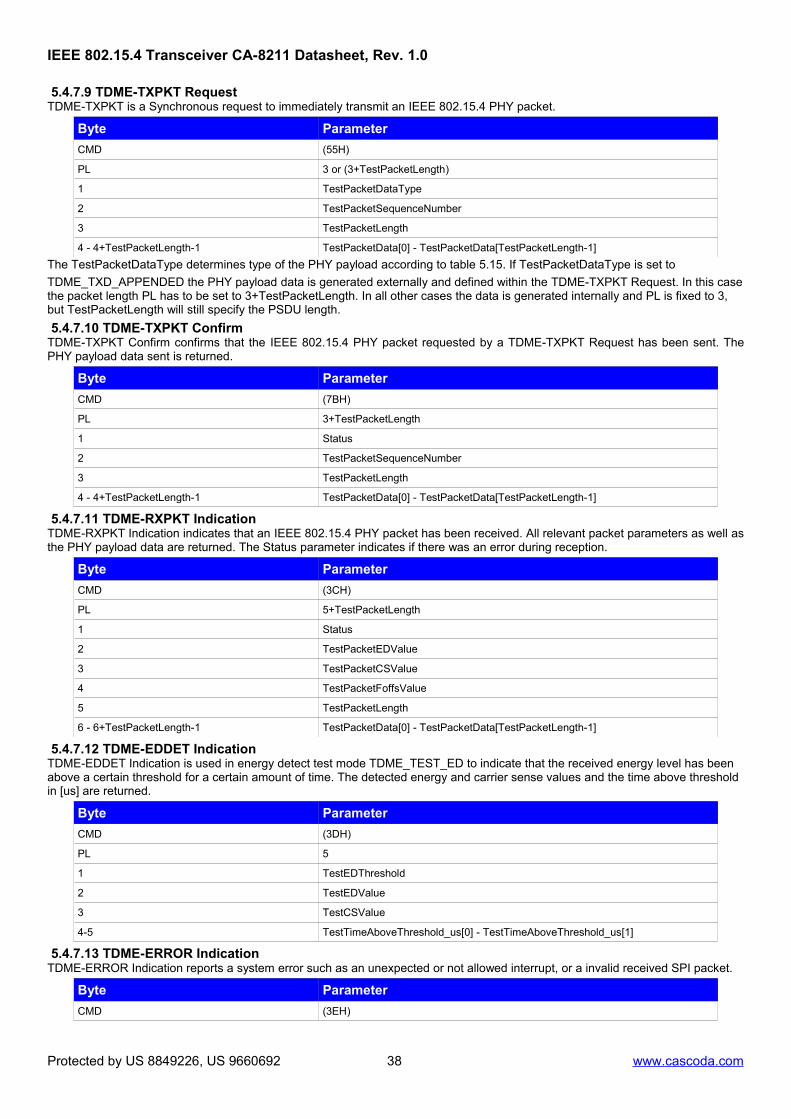
The TestPacketDataType determines type of the PHY payload according to table 5.15. If TestPacketDataType is set to
TDME_TXD_APPENDED the PHY payload data is generated externally and defined within the TDME-TXPKT Request. In this casethe packet length PL has to be set to 3+TestPacketLength. In all other cases the data is generated internally and PL is fixed to 3, but TestPacketLength will still specify the PSDU length.
5.4.7.10 TDME-TXPKT ConfirmTDME-TXPKT Confirm confirms that the IEEE 802.15.4 PHY packet requested by a TDME-TXPKT Request has been sent. ThePHY payload data sent is returned.
5.4.7.11 TDME-RXPKT IndicationTDME-RXPKT Indication indicates that an IEEE 802.15.4 PHY packet has been received. All relevant packet parameters as well asthe PHY payload data are returned. The Status parameter indicates if there was an error during reception.
5.4.7.12 TDME-EDDET IndicationTDME-EDDET Indication is used in energy detect test mode TDME_TEST_ED to indicate that the received energy level has been above a certain threshold for a certain amount of time. The detected energy and carrier sense values and the time above threshold in [us] are returned.
5.4.7.13 TDME-ERROR IndicationTDME-ERROR Indication reports a system error such as an unexpected or not allowed interrupt, or a invalid received SPI packet.
Byte Parameter
CMD (3EH)
Protected by US 8849226, US 9660692 38 www.cascoda.com
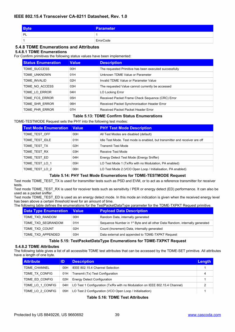
5.4.8 TDME Enumerations and Attributes 5.4.8.1 TDME EnumerationsFor Confirm primitives the following status values have been implemented:
Status Enumeration Value Description
TDME_SUCCESS 00H The requested Primitive has been executed successfully
TDME_UNKNOWN 01H Unknown TDME Value or Parameter
TDME_INVALID 02H Invalid TDME Value or Parameter Value
TDME_NO_ACCESS 03H The requested Value cannot currently be accessed
TDME_LO_ERROR 04H LO Locking Error
TDME_FCS_ERROR 05H Received Packet Frame Check Sequence (CRC) Error
TDME_SHR_ERROR 06H Received Packet Synchronisation Header Error
TDME_PHR_ERROR 07H Received Packet Packet Header Error
Table 5.13: TDME Confirm Status EnumerationsTDME-TESTMODE Request sets the PHY into the following test modes:
Test Mode Enumeration Value PHY Test Mode Description
TDME_TEST_OFF 00H All Test Modes are disabled (default)
TDME_TEST_IDLE 01H Idle Test Mode. Test mode is enabled, but transmitter and receiver are off
TDME_TEST_TX 02H Transmit Test Mode
TDME_TEST_RX 03H Receive Test Mode
TDME_TEST_ED 04H Energy Detect Test Mode (Energy Sniffer)
TDME_TEST_LO_1 05H LO Test Mode 1 (Tx/Rx with no Modulation, PA enabled)
TDME_TEST_LO_2 06H LO Test Mode 2 (VCO Open Loop / Initialisation, PA enabled)
Table 5.14: PHY Test Mode Enumerations for TDME-TESTMODE RequestTest mode TDME_TEST_TX is used for transmitter tests such as PSD and EVM, or to act as a reference transmitter for receiver tests.Test mode TDME_TEST_RX is used for receiver tests such as sensitivity / PER or energy detect (ED) performance. It can also be used as a packet sniffer.Test mode TDME_TEST_ED is used as an energy detect mode. In this mode an indication is given when the received energy level has been above a certain threshold level for an amount of time.The following table defines the enumerations for the TestPacketDataType parameter for the TDME-TXPKT Request primitive.
Data Type Enumeration Value Payload Data Description
TDME_TXD_RANDOM 00H Random Data, internally generated
TDME_TXD_SEQRANDOM 01H Sequence Number in 1st Byte and all other Data Random, internally generated
TDME_TXD_APPENDED 03H Data external and appended to TDME-TXPKT Request
Table 5.15: TestPacketDataType Enumerations for TDME-TXPKT Request
5.4.8.2 TDME AttributesThe following table gives a list of all accessible TDME test attributes that can be accessed by the TDME-SET primitive. All attributeshave a length of one byte.
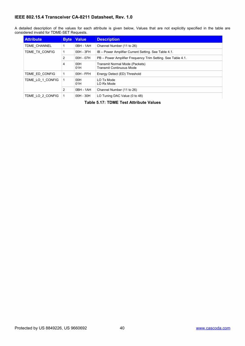
A detailed description of the values for each attribute is given below, Values that are not explicitly specified in the table areconsidered invalid for TDME-SET Requests.
Attribute Byte Value Description
TDME_CHANNEL 1 0BH - 1AH Channel Number (11 to 26)
TDME_TX_CONFIG 1 00H - 3FH IB – Power Amplifier Current Setting. See Table 4.1.
2 00H - 07H PB – Power Amplifier Frequency Trim Setting. See Table 4.1.
4 00H01H
Transmit Normal Mode (Packets)Transmit Continuous Mode
TDME_ED_CONFIG 1 00H - FFH Energy Detect (ED) Threshold
TDME_LO_1_CONFIG 1 00H01H
LO Tx ModeLO Rx Mode
2 0BH - 1AH Channel Number (11 to 26)
TDME_LO_2_CONFIG 1 00H - 30H LO Tuning DAC Value (0 to 48)
Table 5.17: TDME Test Attribute Values
Protected by US 8849226, US 9660692 40 www.cascoda.com
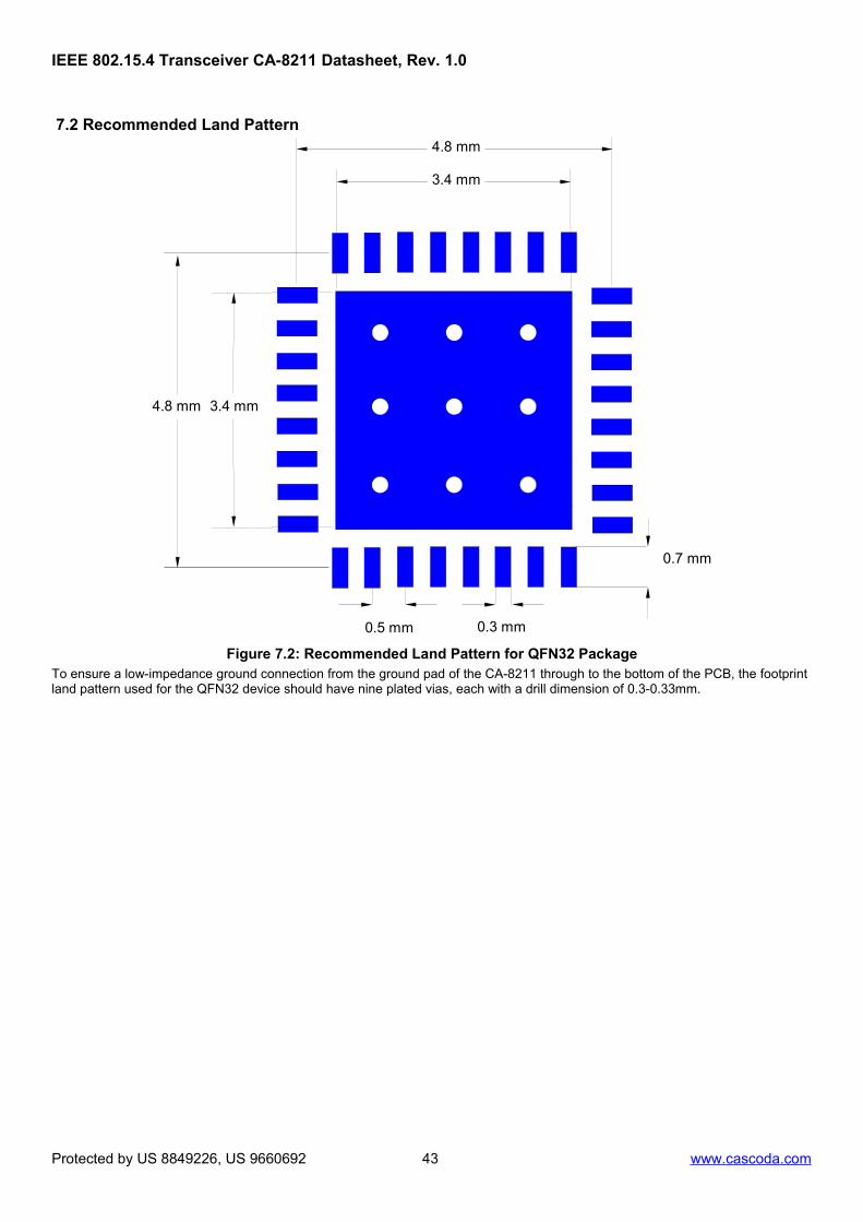
Figure 7.2: Recommended Land Pattern for QFN32 PackageTo ensure a low-impedance ground connection from the ground pad of the CA-8211 through to the bottom of the PCB, the footprint land pattern used for the QFN32 device should have nine plated vias, each with a drill dimension of 0.3-0.33mm.
Protected by US 8849226, US 9660692 43 www.cascoda.com
[1] IEEE Std 802.15.4™-2006: Wireless Medium Access Control (MAC) and Physical Layer (PHY) Specifications for Low-Rate Wireless Personal Area Networks (LR-WPANs)
[2] IEEE Std 802.15.4™-2003: Wireless Medium Access Control (MAC) and Physical Layer (PHY) Specifications for Low-Rate Wireless Personal Area Networks (LR-WPANs)
Protected by US 8849226, US 9660692 44 www.cascoda.com
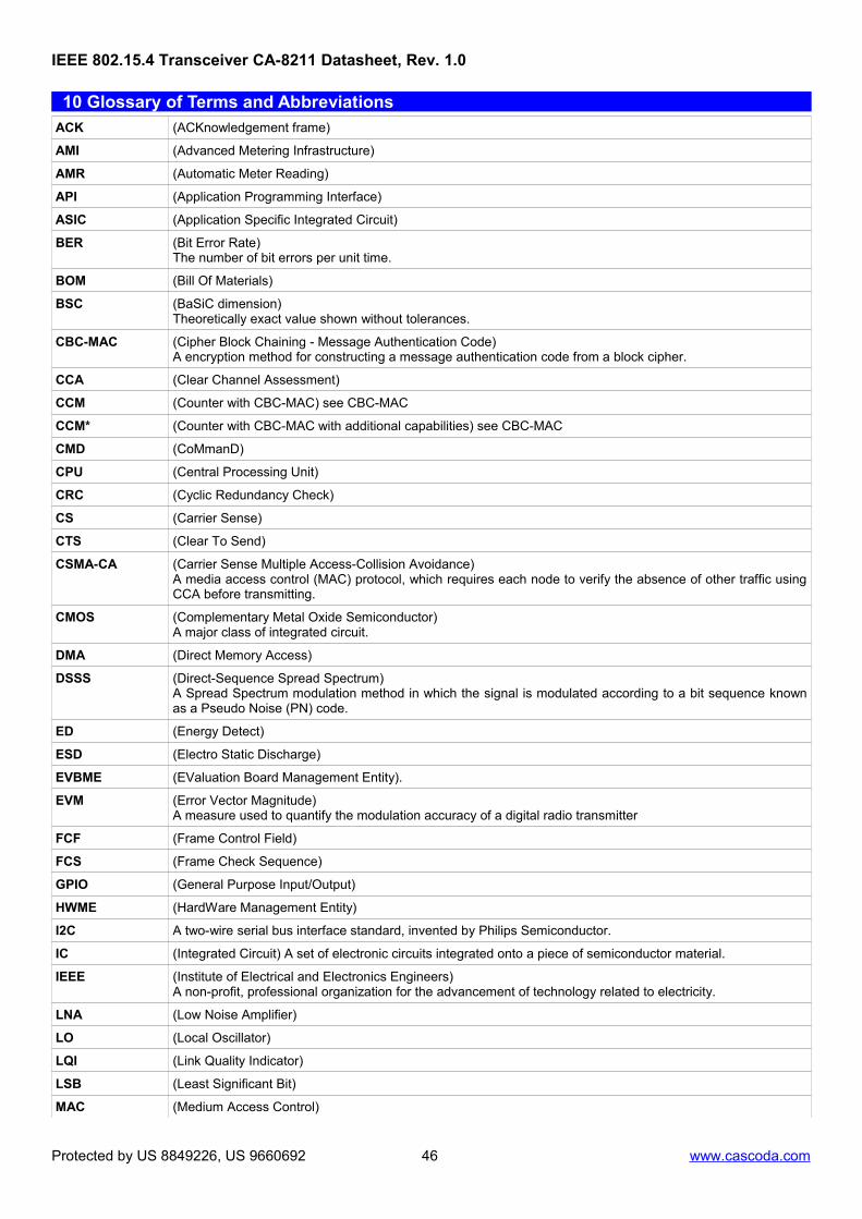
10 Glossary of Terms and AbbreviationsACK (ACKnowledgement frame)
AMI (Advanced Metering Infrastructure)
AMR (Automatic Meter Reading)
API (Application Programming Interface)
ASIC (Application Specific Integrated Circuit)
BER (Bit Error Rate)The number of bit errors per unit time.
BOM (Bill Of Materials)
BSC (BaSiC dimension)Theoretically exact value shown without tolerances.
CBC-MAC (Cipher Block Chaining - Message Authentication Code)A encryption method for constructing a message authentication code from a block cipher.
CCA (Clear Channel Assessment)
CCM (Counter with CBC-MAC) see CBC-MAC
CCM* (Counter with CBC-MAC with additional capabilities) see CBC-MAC
CMD (CoMmanD)
CPU (Central Processing Unit)
CRC (Cyclic Redundancy Check)
CS (Carrier Sense)
CTS (Clear To Send)
CSMA-CA (Carrier Sense Multiple Access-Collision Avoidance)A media access control (MAC) protocol, which requires each node to verify the absence of other traffic usingCCA before transmitting.
CMOS (Complementary Metal Oxide Semiconductor)A major class of integrated circuit.
DMA (Direct Memory Access)
DSSS (Direct-Sequence Spread Spectrum)A Spread Spectrum modulation method in which the signal is modulated according to a bit sequence knownas a Pseudo Noise (PN) code.
ED (Energy Detect)
ESD (Electro Static Discharge)
EVBME (EValuation Board Management Entity).
EVM (Error Vector Magnitude)A measure used to quantify the modulation accuracy of a digital radio transmitter
FCF (Frame Control Field)
FCS (Frame Check Sequence)
GPIO (General Purpose Input/Output)
HWME (HardWare Management Entity)
I2C A two-wire serial bus interface standard, invented by Philips Semiconductor.
IC (Integrated Circuit) A set of electronic circuits integrated onto a piece of semiconductor material.
IEEE (Institute of Electrical and Electronics Engineers)A non-profit, professional organization for the advancement of technology related to electricity.
LNA (Low Noise Amplifier)
LO (Local Oscillator)
LQI (Link Quality Indicator)
LSB (Least Significant Bit)
MAC (Medium Access Control)
Protected by US 8849226, US 9660692 46 www.cascoda.com
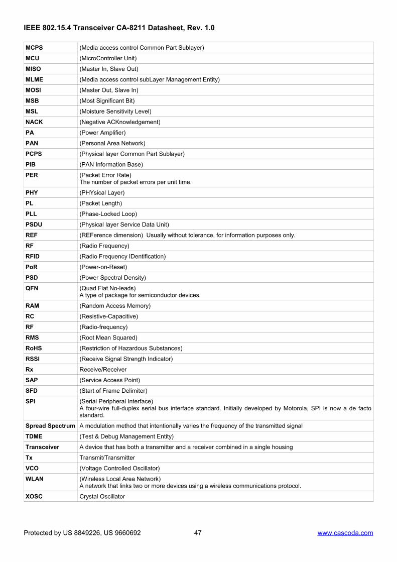
MLME (Media access control subLayer Management Entity)
MOSI (Master Out, Slave In)
MSB (Most Significant Bit)
MSL (Moisture Sensitivity Level)
NACK (Negative ACKnowledgement)
PA (Power Amplifier)
PAN (Personal Area Network)
PCPS (Physical layer Common Part Sublayer)
PIB (PAN Information Base)
PER (Packet Error Rate)The number of packet errors per unit time.
PHY (PHYsical Layer)
PL (Packet Length)
PLL (Phase-Locked Loop)
PSDU (Physical layer Service Data Unit)
REF (REFerence dimension) Usually without tolerance, for information purposes only.
RF (Radio Frequency)
RFID (Radio Frequency IDentification)
PoR (Power-on-Reset)
PSD (Power Spectral Density)
QFN (Quad Flat No-leads)A type of package for semiconductor devices.
RAM (Random Access Memory)
RC (Resistive-Capacitive)
RF (Radio-frequency)
RMS (Root Mean Squared)
RoHS (Restriction of Hazardous Substances)
RSSI (Receive Signal Strength Indicator)
Rx Receive/Receiver
SAP (Service Access Point)
SFD (Start of Frame Delimiter)
SPI (Serial Peripheral Interface)A four-wire full-duplex serial bus interface standard. Initially developed by Motorola, SPI is now a de factostandard.
Spread Spectrum A modulation method that intentionally varies the frequency of the transmitted signal
TDME (Test & Debug Management Entity)
Transceiver A device that has both a transmitter and a receiver combined in a single housing
Tx Transmit/Transmitter
VCO (Voltage Controlled Oscillator)
WLAN (Wireless Local Area Network)A network that links two or more devices using a wireless communications protocol.
XOSC Crystal Oscillator
Protected by US 8849226, US 9660692 47 www.cascoda.com