IEEE Std 1249-1996 IEEE Guide for Computer-Based Control for Hydroelectric Power Plant Automation Sponsor Energy Development and Power Generation Committee of the IEEE Power Engineering Society Approved 10 December 1996 IEEE Standards Board Abstract: The application, design concepts, and implementation of computer-based control systems for hydroelectric power plant automation is addressed. Functional capabilities, performance requirements, interface requirements, hardware considerations, and operator training are discussed. Recommendations for system testing and acceptance are provided, and case studies of actual computer-based control applications are presented. Keywords: alarm processing, automatic generation control, automatic voltage control, computer-based automation, closed-loop control, data acquisition, hydroelectric, power plant, network bus configurations, system architecture, system performance The Institute of Electrical and Electronics Engineers, Inc. 345 East 47th Street, New York, NY 10017-2394, USA Copyright ' 1997 by the Institute of Electrical and Electronics Engineers, Inc. All rights reserved. Published 1997. Printed in the United States of America. ISBN 1-55937-864-6 No part of this publication may be reproduced in any form, in an electronic retrieval system or otherwise, without the prior written permission of the publisher.
Transcript
IEEE Std 1249-1996
IEEE Guide for Computer-Based Control for Hydroelectric Power Plant Automation
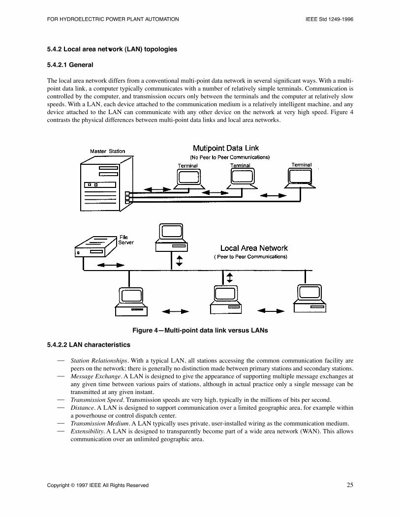
Sponsor
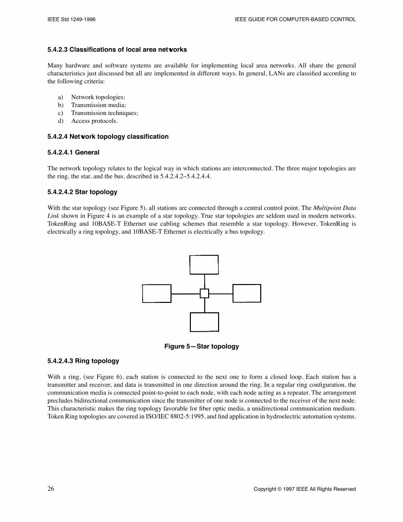
Energy Development and Power Generation Committeeof theIEEE Power Engineering Society
Approved 10 December 1996
IEEE Standards Board
Abstract:
The application, design concepts, and implementation of computer-based control systems forhydroelectric power plant automation is addressed. Functional capabilities, performance requirements,interface requirements, hardware considerations, and operator training are discussed. Recommendationsfor system testing and acceptance are provided, and case studies of actual computer-based controlapplications are presented.
Keywords:
alarm processing, automatic generation control, automatic voltage control, computer-basedautomation, closed-loop control, data acquisition, hydroelectric, power plant, network bus configurations,system architecture, system performance
The Institute of Electrical and Electronics Engineers, Inc.
345 East 47th Street, New York, NY 10017-2394, USA
All rights reserved. Published 1997. Printed in the United States of America.
ISBN 1-55937-864-6
No part of this publication may be reproduced in any form, in an electronic retrieval system or otherwise, without theprior written permission of the publisher.
IEEE Standards
documents are developed within the IEEE Societies and the Standards Coordinating Committees ofthe IEEE Standards Board. Members of the committees serve voluntarily and without compensation. They are notnecessarily members of the Institute. The standards developed within IEEE represent a consensus of the broadexpertise on the subject within the Institute as well as those activities outside of IEEE that have expressed an interestin participating in the development of the standard.
Use of an IEEE Standard is wholly voluntary. The existence of an IEEE Standard does not imply that there are no otherways to produce, test, measure, purchase, market, or provide other goods and services related to the scope of the IEEEStandard. Furthermore, the viewpoint expressed at the time a standard is approved and issued is subject to changebrought about through developments in the state of the art and comments received from users of the standard. EveryIEEE Standard is subjected to review at least every Þve years for revision or reafÞrmation. When a document is morethan Þve years old and has not been reafÞrmed, it is reasonable to conclude that its contents, although still of somevalue, do not wholly reßect the present state of the art. Users are cautioned to check to determine that they have thelatest edition of any IEEE Standard.
Comments for revision of IEEE Standards are welcome from any interested party, regardless of membership afÞliationwith IEEE. Suggestions for changes in documents should be in the form of a proposed change of text, together withappropriate supporting comments.
Interpretations: Occasionally questions may arise regarding the meaning of portions of standards as they relate tospeciÞc applications. When the need for interpretations is brought to the attention of IEEE, the Institute will initiateaction to prepare appropriate responses. Since IEEE Standards represent a consensus of all concerned interests, it isimportant to ensure that any interpretation has also received the concurrence of a balance of interests. For this reason,IEEE and the members of its societies and Standards Coordinating Committees are not able to provide an instantresponse to interpretation requests except in those cases where the matter has previously received formalconsideration.
Comments on standards and requests for interpretations should be addressed to:
Authorization to photocopy portions of any individual standard for internal or personal use is granted by the Instituteof Electrical and Electronics Engineers, Inc., provided that the appropriate fee is paid to Copyright Clearance Center.To arrange for payment of licensing fee, please contact Copyright Clearance Center, Customer Service, 222 RosewoodDrive, Danvers, MA 01923 USA; (508) 750-8400. Permission to photocopy portions of any individual standard foreducational classroom use can also be obtained through the Copyright Clearance Center.
Note: Attention is called to the possibility that implementation of this standard may require use of subject mattercovered by patent rights. By publication of this standard, no position is taken with respect to the existence orvalidity of any patent rights in connection therewith. The IEEE shall not be responsible for identifying patents forwhich a license may be required by an IEEE standard or for conducting inquiries into the legal validity or scopeof those patents that are brought to its attention.
iii
Introduction
(This introduction is not part of IEEE Std 1249-1996, IEEE Guide for Computer-Based Control for Hydroelectric Power PlantAutomation.)
Automation of hydroelectric generating plants has been a known technology for many years. Due to the relativesimplicity of the control logic for hydroelectric power plants, the application of computer-based control has lagged,compared to other types of generating stations, such as fossil. Now that computer-based control can be implementedfor comparable costs as relay-based logic and can incorporate additional features, it is being applied in hydroelectricpower stations worldwide, both in new installations and in the rehabilitation of older plants.
The guide is directed to the practicing engineer who has some familiarity with computer-based control systems. Theauthors have attempted to make the document a comprehensive guide to the application of such systems tohydroelectric plants. It begins with a discussion of computer-based control system functional capabilities, pursues dataacquisition, alarm processing, report generation, and operator training, as well as various system architecture andnetwork bus conÞgurations. System performance and testing are discussed, and Þnally, four case studies of actualcomputer-based hydroelectric control applications are presented.
The following persons were participants in the effort of the IEEE P1249 Working Group:
Horst R. Butz
, Chair
D. B. Seely
, Vice Chair
B. BerrethJ. M. BogertS. R. BrockschinkH. R. DavisJ. S. EdmondsR. C. GrovesJ. H. GurneyR. D. HandelR. E. HowellR. J. HughesJ. H. Jones
D. L. KornegayC. A. Lennon, Jr.S. LindstromL. D. LongC. F. MalmD. R. McCabeP. MicaleA. MickeviciusL. J. Miller, IIIE. P. MiskaH. Naeff
D. M. NailG. D. OsburnJ. QuinnL. N. RodlandA. RoehlH. RogneF. RustW. W. TerryV. WarrenL. WozniakJ. Yale
The following persons were on the balloting committee:
L. D. BoydstunSteven R. BrockschinkR. O. BylinD. DiamantGary R. EngmannWilliam W. FieldsJames H. GurneyThomas J. HammonsKenneth HancockRobert D. HandelThomas A. Higgins
Robert E. HowellJ. D. HurleyHarry J. JonesDavid L. KornegayPeter H. LandrieuCharles A. Lennon Jr.Gregory L. LuriJ. T. MadillO. P. MalikOmar S. MazzoniDonald R. McCabe
Marco W. MigliaroWilliam R. MoonCharles R. PopeBradford M. RadimerGreg P. RahmanJ. R. RibeiroDerek M. SawyerKen H. SebraJames E. StonerMalcolm V. ThadenEdward T. Voelker
iv
When the IEEE Standards Board approved this guide on 10 December 1996, it had the following membership:
Donald C. Loughry
, Chair
Richard J. Holleman
, Vice Chair
Andrew G. Salem
, Secretary
Gilles A. BarilClyde R. CampJoseph A. CannatelliStephen L. DiamondHarold E. EpsteinDonald C. FleckensteinJay Forster*Donald N. HeirmanBen C. Johnson
E. G. "Al" KienerJoseph L. Koepfinger*Stephen R. LambertLawrence V. McCallL. Bruce McClungMarco W. MigliaroMary Lou PadgettJohn W. Pope
Jose R. RamosArthur K. ReillyRonald H. ReimerGary S. RobinsonIngo R�schJohn S. RyanChee Kiow TanLeonard L. TrippHoward L. Wolfman
*Member Emeritus
Also included are the following nonvoting IEEE Standards Board liaisons:
Satish K. Aggarwal Alan H. Cookson Chester C. Taylor
4.1 General ....................................................................................................................................................... 54.2 Control capabilities .................................................................................................................................... 64.3 Data acquisition capabilities .................................................................................................................... 144.4 Alarm processing and diagnostics............................................................................................................ 154.5 Report generation ..................................................................................................................................... 164.6 Maintenance management interface......................................................................................................... 164.7 Data archival and retrieval ....................................................................................................................... 164.8 Operation scheduling and forecasting...................................................................................................... 164.9 Data access ............................................................................................................................................... 174.10 Operator simulation training .................................................................................................................... 174.11 Typical control parameters....................................................................................................................... 17
5. System architecture, communications, and databases.......................................................................................18
5.1 General ..................................................................................................................................................... 185.2 System classification................................................................................................................................ 195.3 System architecture characteristics .......................................................................................................... 205.4 Control data networks .............................................................................................................................. 245.5 Data bases and software configuration .................................................................................................... 29
6. User and plant interfaces...................................................................................................................................31
6.1 User interfaces.......................................................................................................................................... 316.2 Plant interfaces ......................................................................................................................................... 32
7. System performance..........................................................................................................................................34
8. System backup capabilities ...............................................................................................................................38
8.1 General ..................................................................................................................................................... 388.2 Design principles...................................................................................................................................... 398.3 Basic functions ......................................................................................................................................... 398.4 Design of equipment for backup control.................................................................................................. 398.5 Alarm handling ........................................................................................................................................ 408.6 Protective function ................................................................................................................................... 41
vi
CLAUSE PAGE
9. Site integration and support systems.................................................................................................................41
9.1 Interface to existing equipment................................................................................................................ 419.2 Environmental conditions ........................................................................................................................ 419.3 Power source ............................................................................................................................................ 429.4 Supervision of existing contact status points ........................................................................................... 429.5 Supervision of existing transducers ......................................................................................................... 429.6 Supervision of existing control output points .......................................................................................... 439.7 Grounding ................................................................................................................................................ 439.8 Static control ............................................................................................................................................ 43
10. Recommended test and acceptance criteria.......................................................................................................43
10.1 Specific test requirements ........................................................................................................................ 4410.2 Quality assurance ..................................................................................................................................... 4510.3 Acceptance ............................................................................................................................................... 45
11. System management .........................................................................................................................................45
12. Case studies.......................................................................................................................................................47
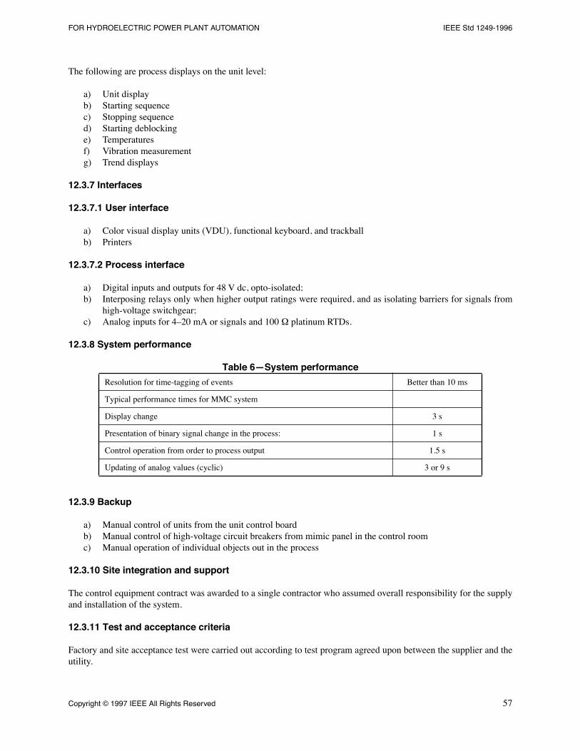
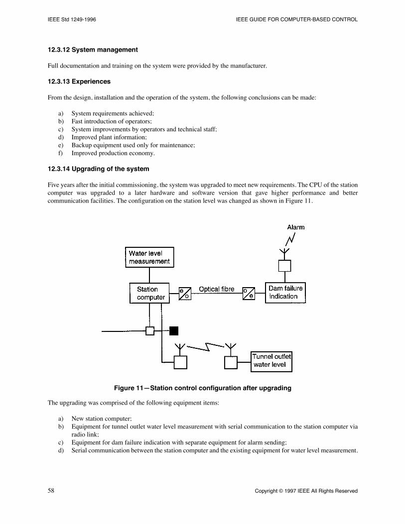
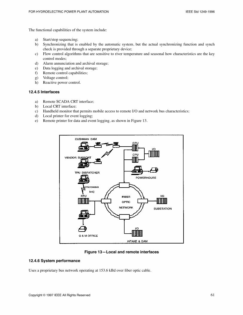
12.1 Automation of the Conowingo Hydroelectric Station ............................................................................. 4712.2 Computer-based control system at Waddell Pump-Generating Plant...................................................... 5012.3 Retrofit of Tr�ngslet Hydro Power Station .............................................................................................. 5412.4 Computer-based control system at Wynoochee Hydroelectric Project.................................................... 59
Annex A Bibliography (Informative)............................................................................................................................63
IEEE Guide for Computer-Based Control for Hydroelectric Power Plant Automation
1. Overview
1.1 Scope
This guide addresses the application, design concepts, and implementation of computer-based control systems forhydroelectric plant automation. It addresses functional capabilities, performance requirements, interface requirements,hardware considerations, and operator training. It includes recommendations for system testing and acceptance.Finally, case studies of actual computer-based automatic control applications are presented.
The automation of control and data logging functions has relieved the plant operator of these tasks, allowing theoperator more time to concentrate on other duties. In many cases, the plant's operating costs can be signiÞcantlyreduced by automation (primarily via staff reduction) while still maintaining a high level of unit control reliability.
Automatic control systems for hydroelectric units based on electromechanical relay logic have been in general use fora number of years and, in fact, were considered standard practice for the industry. Within the last decade,microprocessor-based controllers have become available that are suitable for operation in a power plant environment.These computer-based systems have been applied for data logging, alarm monitoring, and unit and plant control.Advantages of computer-based control include use of graphical user interfaces, the incorporation of sequence of eventsand trending into the control system, the incorporation of artiÞcial intelligence and expert system capabilities, andreduced plant life cycle cost.
1.2 Purpose
This guide is directed to the practicing engineer who has some familiarity with computer-based control systems andwho is designing or implementing hydroelectric unit or plant control systems, either in a new project or as a retroÞt toan existing one. This guide assumes that the control system logic has already been deÞned; therefore, its developmentis not covered. For information on control sequence logic, the reader is directed to the IEEE guides for control ofhydroelectric power plants listed in Clause 2. of this guide.
IEEE Std 1249-1996 IEEE GUIDE FOR COMPUTER-BASED CONTROL
2. References
ANSI C63.4-1992, Methods of Measurement of Radio-Noise Emissions from Low-Voltage Electrical and ElectronicEquipment in the Range of 9 kHzÐ40 GHz.
1
IEEE Std 100-1996, The IEEE Standard Dictionary of Electrical and Electronics Terms.
2
IEEE Std 485-1983, IEEE Recommended Practice for Sizing Large Lead Storage Batteries for Generating Stationsand Substations (ANSI).
IEEE Std 610-1990, IEEE Standard Computer Dictionary: A Compilation of IEEE Standard Computer Glossaries(ANSI).
IEEE Std 1010-1987 (Reaff 1992), IEEE Guide for Control of Hydroelectric Power Plants (ANSI).
IEEE Std 1020-1988 (Reaff 1994), IEEE Guide for Control of Small Hydroelectric Power Plants. (ANSI)
IEEE Std 1046-1991 (Reaff 1996), IEEE Guide for Distributed Digital Control and Monitoring for Power Plants(ANSI).
IEEE Std 1147-1991 (Reaff 1996), IEEE Guide for the Rehabilitation of Hydroelectric Power Plants (ANSI)
IEEE Std C37.1-1994, IEEE Standard DeÞnition, SpeciÞcation, and Analysis of Systems Used for SupervisoryControl, Data Acquisition, and Automation Control (ANSI).
IEEE Std C37.90.1-1989 (Reaff 1994), IEEE Standard for Surge Withstand Capability (SWC) Tests for ProtectiveRelays and Relay Systems (ANSI).
IEEE Std C37.90.2-1987, IEEE Trial Use Standard Withstand Capability of Relay Systems to RadiatedElectromagnetic Interference from Transceivers (ANSI).
IEEE P1379 (Draft 5, September 1996), IEEE Trial Use Recommended Practice for Data Communications BetweenIntelligent Electronic Devices and Remote Terminal Units in a Substation.
3
IISA/SAMA PMC 31.1-1978, Electromagnetic Susceptibility of Process Control Instrumentation.
4
ISO/IEC 8802-3: 1996 (ANSI/IEEE Std 802.3, 1996 Edition) Information technologyÑTelecommunications andinformation exchange between systemsÑlocal and Metropolitan Area NetworksÑSpeciÞc requirementsÑPart 3:Carrier sense multiple access with collision detection (CSMA/CD) access method and physical layer speciÞcations.
5
IEEE Std ISO/IEC 8802-4; 1990 [ANSI/IEEE 802.4-1990 (Reaff 1995)], Information processing systemsÑlocal areanetworksÑPart 4: Token-passing bus access method and physical layer speciÞcations.
IEEE Std ISO/IEC 8802-4; 1990 [ANSI/IEEE 802.4-1990 (Reaff 1995)], Information processing systemsÑlocal areanetworksÑPart 4: Token-passing bus access method and physical layer speciÞcations.
1
ANSI publications are available from the Sales Department, American National Standards Institute, 11 West 42nd Street, 13th Floor, New York,NY 10036, USA.
2
IEEE publications are available from the Institute of Electrical and Electronics Engineers, 445 Hoes Lane, Po. Box 1331, Piscataway, NJ 08855-1331, USA.
3
This IEEE standards project was not approved by the IEEE Standards Board at the time this publication went to press. For information aboutobtaining a draft, contact the IEEE.
4
This document is available from the Instrument Society of America, 67 Alexander Drive, Research Triangle Park, NC 27709.
5
ISO publications are available from the ISO Central Secretariat, Case Postale 56, 1 rue de Varemb�, CH-1211, Gen�ve 20, Switzerland/Suisse. ISOpublications are also available in the United States from the Sales Department, American National Standards Institute, 11 West 42nd Street, 13thFloor, New York, NY 10036, USA.
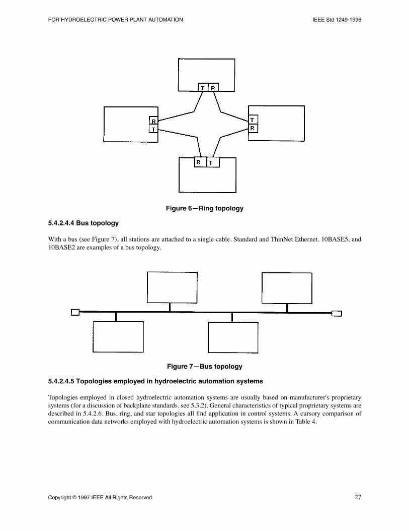
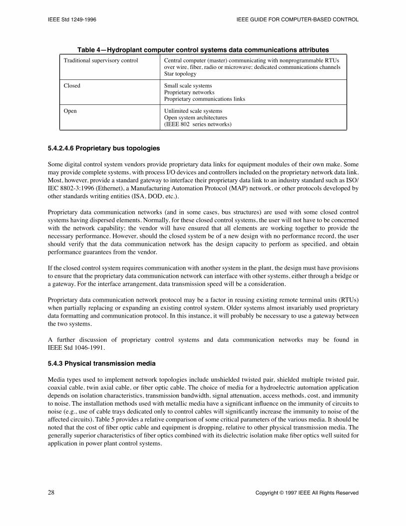
FOR HYDROELECTRIC POWER PLANT AUTOMATION IEEE Std 1249-1996
ISO/IEC 8802-5: 1995 (ANSI/IEEE Std 802.5, 1995 Edition), Information technology-Telecommunications andinformation exchange between systemsÑlocal and Metropolitan Area NetworksÑSpeciÞc requirementsÑPart 5:Token ring access method and physical layer speciÞcation.
3. Definitions
The deÞnitions provided here reßect common industry usage as related to automation of hydroelectric power plants,and may not in all instances be in accordance with IEEE Std 100-1996, or IEEE Std 610-1990, or other applicablestandards. For more rigorous deÞnitions, or for deÞnitions not covered herein, the reader is referred to the appropriateIEEE standards.
3.1 analog-to-digital (a/d) conversion:
Production of a digital output corresponding to the value of an analog inputquantity.
3.2 automatic control:
An arrangement of electrical controls that provides for switching or controlling, or both, ofequipment in a speciÞc sequence and under predetermined conditions without operator intervention.
3.3 automatic generation control (AGC):
The capability to regulate the power output of selectable units in responseto total power plant output, tie-line power ßow, and power system frequency.
3.4 automatic voltage control (AVC):
The capability to regulate a speciÞc power system voltage, via adjustment ofunit excitation within the limits of unit terminal voltage and VAR capability.
3.5 automation hierarchy:
The design and implementation of automation functions in a multilevel structure, such aslocal level, group level, unit level, etc.
3.6 availability:
The ratio of uptime (system functional) to uptime plus downtime (system not functional).
3.7 backplane:
A circuit board with connectors or sockets that provides a standardized method of transferring signalsbetween plug-in circuit cards.
3.8 bridge:
A device that allows two networks of the same or similar technology to communicate.
3.9 centralized control:
A control location one step removed from local control; remote from the equipment orgenerating unit, but still within the conÞnes of the plant (e.g., controls located in a plant control room).
3.10 closed loop control:
A type of automatic control in which control actions are based on signals fed back from thecontrolled equipment or system. For example, a plant control system can control the power output of a multi-unithydroelectric power plant by monitoring the total plant megawatt value and, in response, by controlling the turbinegovernors of each unit, change the plant power output to meet system needs.
3.11 computer-based automation:
The use of computer components, such as logic controllers, sequence controllers,modulating controllers, and processors in order to bring plant equipment into operation, optimize operation in asteady-state condition, and shut down the equipment in the proper sequence under safe operating conditions.
3.12 control hierarchy:
A system organization incorporating multiple levels of control responsibility.
3.13 control philosophy:
The total concept on which a power plant control system is based.
3.14 data acquisition system:
A centralized system that receives data from one or more remote points. Data may betransported in either analog or digital form.
3.15 database:
The collection of stored data regarding the process variables and processing procedures.
3.16 data bus:
A control network technology in which data stations share one single communication system medium.Messages propagate over the entire medium and are received by all data stations simultaneously.
3.17 device (electrical equipment):
An operating element such as a relay, contactor, circuit breaker, switch or valve,used to perform a given function in the operation of electrical equipment.
IEEE Std 1249-1996 IEEE GUIDE FOR COMPUTER-BASED CONTROL
3.18 digital-to-analog (d/a) conversion:
Production of an analog signal whose magnitude is proportional to the valueof a digital input.
3.19 distributed processing:
A design in which data is processed in multiple processors. Processing functions couldbe shared by the processors throughout the control system.
3.20 event:
A discrete change of state (status) of a system or device.
3.21 expert system:
Computer programs that embody judgmental and experimental knowledge about an application.Expert systems are able to reach decisions from new, uncertain and incomplete information with a speciÞed degree ofcertainty. Expert system abilities include; making logical inferences under unforeseen conditions; using subjective andformal knowledge; explaining the procedures used to reach a conclusion; growing in effectiveness as embeddedexpertise is expanded and modiÞed.
3.22 Þrmware:
Hardware used for the nonvolatile storage of instructions or data that can be read only by thecomputer. Stored information is not alterable by any computer program.
3.23 gateway:
A device that allows two networks of differing technology to communicate.
3.24 local control:
For auxiliary equipment, controls that are located at the equipment itself or within sight of theequipment. For a generating station, the controls that are located on the unit switchboard/governor control station.
3.25 logic:
(control or relay logic) Predetermined sequence of operation of relays and other control devices.
3.26 manual control:
Control in which the system or main device, whether direct or power-aided in operation, isdirectly controlled by an operator.
3.27 mean-time-between-failure (MTBF):
The time interval (hours) that may be expected between failures of anoperating equipment.
3.28 mean-time-to-repair (MTTR):
The time interval (hours) that may be expected to return a failed equipment toproper operation.
3.29 modem:
A modulator/demodulator device that converts serial binary digital data to and from the signal formappropriate for an analog communication channel.
3.30 monitoring:
A means of providing automatic performance supervision and alarming of the status of the processto personnel and control programs.
3.31 offsite control:
Controls that are not resident at the plant (e.g., at a switchyard, another plant, etc.).
3.32 open loop control:
A form of control without feedback.
3.33 proportional integral derivative (PID) [control system]:
Control action in which the output is proportional toa linear combination of the input, the time integral of input, and the time rate of change of input. Commonly used inhydroelectric applications for the control of a generator's real power, reactive power, or ßow.
3.34 pixel:
In image processing, the smallest element of a digital image that can be assigned a gray level.
3.35 programmable logic controller (PLC):
Solid state control system with programming capability that performsfunctions similar to a relay logic system.
3.36 protocol:
A structured data format required to initiate and maintain communication.
3.37 relay, interposing:
A device that enables the energy in a high-power circuit to be switched by a low-powercontrol signal.
3.38 remote control:
Control of a device from a distant point.
3.39 reliability:
The characteristic of an item or system expressed by the probability that it will perform a requiredmission under stated conditions for a stated mission time.
3.40 response time:
The elapsed time between the moment when a signal is originated in an input device until themoment the corresponding processed signal is made available to the output device(s), under deÞned system loadingconditions.
FOR HYDROELECTRIC POWER PLANT AUTOMATION IEEE Std 1249-1996
3.41 resistance temperature detector (RTD):
A resistor for which the electrical resistivity is a known function of thetemperature.
3.42 scan (interrogation):
The process by which a data acquisition system sequentially interrogates remote stationsfor data at a speciÞc frequency.
3.43 scan cycle:
The time in seconds required to obtain a collection of data (for example, all data from one controller,all data from all controllers, and all data of a particular type from all controllers).
3.44 serial communication:
A method of transmitting information between devices by sending digital data seriallyover a single communication channel.
3.45 sequential control:
A mode of control in which the control actions are executed consecutively.
3.46 supervisory control and data acquisition (SCADA):
A system operating with coded signals overcommunication channels so as to provide control of remote equipment and to acquire information about the status ofthe remote equipment for display or for recording functions.
3.47 user interface:
A functional system used speciÞcally to interface the computer-based control system to theoperator, maintenance personnel, engineer, etc.
4. Functional capabilities
4.1 General
Computer-based automation has enhanced hydroelectric power plant operation and maintenance activities. Manyactivities previously accomplished by plant personnel can now be performed more accurately, safely, and consistentlyby computer-based automation systems. Also, new tasks are within the capabilities of computer-based systems.
Power plant operators have long been responsible for manually performing control and data acquisition tasks. Relaylogic type automatic control systems were, for many years, the only automated control assistance for operations staff.These systems were limited to unit control sequencing (start/stop) and were not easily changed, once installed. Thequality of data acquisition has been subject to the limitations of available staff and human error.
Computer-based control and data acquisition systems have made major changes in the way these tasks are carried out.Power plant operator expertise has been supplemented in many plants by the computer, which can assist with unit start/stop sequencing and data logging; in other plants, the computer has replaced the operator altogether by performingthese tasks. The online diagnostic, corrective, and protective capabilities of these computer systems continue to bedeveloped.
Computer-based automation systems now allow plant owners to operate and maintain their plants in ways not possiblebefore. Control algorithms based on criteria such as efÞciency, automatic generation control, and voltage control allowmore cost effective and safe operation of plants and interconnected power systems. It is now possible to acquire andprocess more data than in the past, so generated reports can keep operators and maintenance staff apprised of the totalplant condition. Maintenance activities are enhanced by the computer's ability to isolate problems, describe trends, andkeep maintenance records.
Computer-based automation systems also permit operation of the power plant, switchyard, and outlet works (spillwaygates, bypass gates and valves, Þshways, Þsh ladders, etc.) from a single control point that can be local, centralized, oroffsite. This one-point control has many advantages, including reduced operations staff, consistent operatingprocedures, and the capability to have all control and data available for reference during normal and abnormalconditions.
Subclauses 4.2Ð4.11 outline the functional capabilities of hydroelectric plant computer-based automation systems.
IEEE Std 1249-1996 IEEE GUIDE FOR COMPUTER-BASED CONTROL
4.2 Control capabilities
4.2.1 Control hierarchy
A general hierarchy of control for hydroelectric power plants is deÞned in IEEE Std 1010-1987.
6
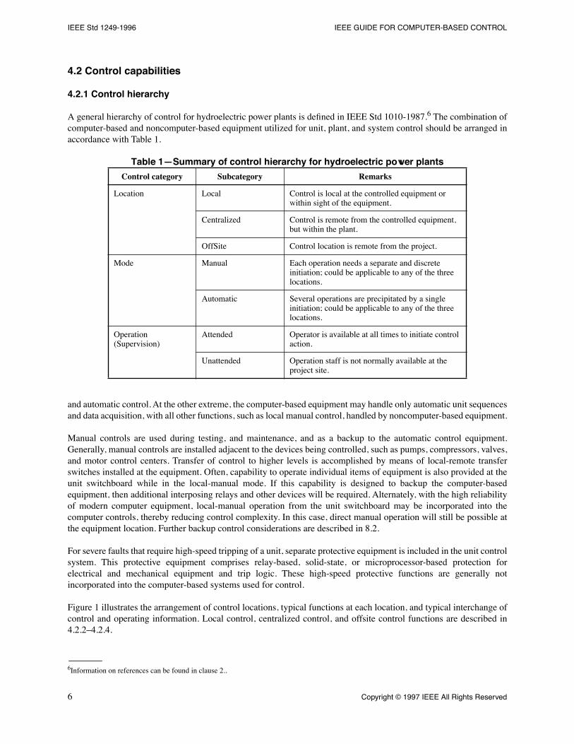
The combination ofcomputer-based and noncomputer-based equipment utilized for unit, plant, and system control should be arranged inaccordance with Table 1.
Table 1ÑSummary of control hierarchy for hydroelectric power plants
and automatic control. At the other extreme, the computer-based equipment may handle only automatic unit sequencesand data acquisition, with all other functions, such as local manual control, handled by noncomputer-based equipment.
Manual controls are used during testing, and maintenance, and as a backup to the automatic control equipment.Generally, manual controls are installed adjacent to the devices being controlled, such as pumps, compressors, valves,and motor control centers. Transfer of control to higher levels is accomplished by means of local-remote transferswitches installed at the equipment. Often, capability to operate individual items of equipment is also provided at theunit switchboard while in the local-manual mode. If this capability is designed to backup the computer-basedequipment, then additional interposing relays and other devices will be required. Alternately, with the high reliabilityof modern computer equipment, local-manual operation from the unit switchboard may be incorporated into thecomputer controls, thereby reducing control complexity. In this case, direct manual operation will still be possible atthe equipment location. Further backup control considerations are described in 8.2.
For severe faults that require high-speed tripping of a unit, separate protective equipment is included in the unit controlsystem. This protective equipment comprises relay-based, solid-state, or microprocessor-based protection forelectrical and mechanical equipment and trip logic. These high-speed protective functions are generally notincorporated into the computer-based systems used for control.
Figure 1 illustrates the arrangement of control locations, typical functions at each location, and typical interchange ofcontrol and operating information. Local control, centralized control, and offsite control functions are described in4.2.2Ð4.2.4.
6
Information on references can be found in clause 2..
Control category Subcategory Remarks
Location Local Control is local at the controlled equipment or within sight of the equipment.
Centralized Control is remote from the controlled equipment, but within the plant.
OffSite Control location is remote from the project.
Mode Manual Each operation needs a separate and discrete initiation; could be applicable to any of the three locations.
Automatic Several operations are precipitated by a single initiation; could be applicable to any of the three locations.
Operation (Supervision)
Attended Operator is available at all times to initiate control action.
Unattended Operation staff is not normally available at the project site.
FOR HYDROELECTRIC POWER PLANT AUTOMATION IEEE Std 1249-1996
Figure 1ÑRelationship of local, centralized, and offsite control
4.2.2 Local control
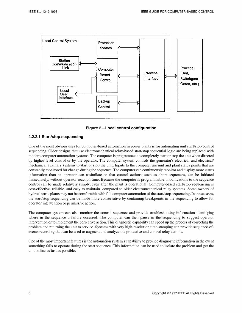
Local control can be provided by equipment located near the generating unit itself. The local unit computer is part ofthis equipment and backup manual control may be desired depending on the operator's design philosophy. Where thereare multiple units in a plant, one computer is typically allocated to each unit. The local unit computer interfaces tohigher level plant or offsite computers exchanging control signals and data without the need for additional wiring.Figure 2 illustrates the local control conÞguration.
IEEE Std 1249-1996 IEEE GUIDE FOR COMPUTER-BASED CONTROL
Figure 2ÑLocal control configuration
4.2.2.1 Start/stop sequencing
One of the most obvious uses for computer-based automation in power plants is for automating unit start/stop controlsequencing. Older designs that use electromechanical relay-based start/stop sequential logic are being replaced withmodern computer automation systems. The computer is programmed to completely start or stop the unit when directedby higher level control or by the operator. The computer system controls the generator's electrical and electrical/mechanical auxiliary systems to start or stop the unit. Inputs to the computer are unit and plant status points that areconstantly monitored for change during the sequence. The computer can continuously monitor and display more statusinformation than an operator can assimilate so that control actions, such as abort sequences, can be initiatedimmediately, without operator reaction time. Because the computer is programmable, modiÞcations to the sequencecontrol can be made relatively simply, even after the plant is operational. Computer-based start/stop sequencing iscost-effective, reliable, and easy to maintain, compared to older electromechanical relay systems. Some owners ofhydroelectric plants may not be comfortable with full computer automation of the start/stop sequencing. In these cases,the start/stop sequencing can be made more conservative by containing breakpoints in the sequencing to allow foroperator intervention or permissive action.
The computer system can also monitor the control sequence and provide troubleshooting information identifyingwhere in the sequence a failure occurred. The computer can then pause in the sequencing to suggest operatorintervention or to implement the corrective action. This diagnostic capability can speed up the process of correcting theproblem and returning the unit to service. Systems with very high-resolution time stamping can provide sequence-of-events recording that can be used to augment and analyze the protective and control relay actions.
One of the most important features is the automation system's capability to provide diagnostic information in the eventsomething fails to operate during the start sequence. This information can be used to isolate the problem and get theunit online as fast as possible.
FOR HYDROELECTRIC POWER PLANT AUTOMATION IEEE Std 1249-1996
Examples of some of the equipment controlled and monitored during the start/stop sequence are as follows:
a) Intake gate or inlet valve;b) Governor hydraulic oil system;c) Gate limit position;d) Gate position;e) High pressure oil system for the thrust bearing;f) Mechanical brakes;g) Cooling water system;h) Excitation equipment;i) Unit speed;j) Protective relaying status;k) Unit alarms;l) Unit breaker status.
4.2.2.2 Synchronizing
Synchronizing has traditionally been performed either manually or by a dedicated automatic synchronizer unit. Today,automatic synchronizers use computer technology to optimize their performance.
In some cases, the synchronizing function is performed by the plant computer-based automation system.Synchronizing is a critical function that requires accurate and reliable monitoring of voltage magnitude, frequency,and phase angle. Not all systems can provide the synchronizing function as part of the computer-based automationsystem. The advantages of the synchronizing function being internal to the automation system include less plantwiring, less maintenance, reduced installation costs, and much better diagnostic capabilities. For security, asynchrocheck relay is typically used as a permissive for the circuit breaker close.
4.2.2.3 Synchronous condenser mode
Hydroelectric generating units are often used in synchronous condenser mode where real power output is negative (theunit is running as a motor) while the unit is online and excited. One reason for this is to provide reactive power control,as described below. Synchronous condenser mode is generally dispatched according to prevailing power ßowconditions, but can be regulated automatically by the computer-based control system to achieve optimal real andreactive power capability and maximum transmission utilization.
In cases where a turbine is located below the tailwater level and runs as a synchronous condenser, the water is expelledfrom the runner area by compressed air to reduce power losses and turbine wear and tear. The computer-basedautomation system can control the auxiliary devices and monitor the generator during this mode of operation. Forexample, the automation system can override the reverse power relay during this mode of operation.
Another purpose of synchronous condenser operation is to provide readily available, real-power spinning reservedictated by power system operating requirements. Computer-based control schemes can be useful in efÞciently andautomatically performing this mode of operation.
4.2.2.4 Pumped storage control
The computer-based automation system can provide the complete control necessary for a unit to operate in pumpingor generating mode. The system can control the switchgear and related equipment necessary to run the unit in eithermode. Some basic features easy to implement in a computer-based control system include providing a run timesummary of units in the pump mode, providing an automatic restart timer feature in the event the unit fails to startproperly, and determining which unit should be started to balance the run time between multiple units. All thesefeatures can be implemented at the power plant level and would involve control of the units directly or through unitcontrollers based on the conÞguration of the automation system. The main advantages of using a computer-based
IEEE Std 1249-1996 IEEE GUIDE FOR COMPUTER-BASED CONTROL
system to control the pumped storage mode of operation includes easy maintenance, easy modiÞcations, and availablediagnostic information.
4.2.2.5 Turbine operation optimization
There are numerous possibilities for optimizing individual unit turbine operation through the application of customsoftware algorithms. Depending on the parameters monitored and control sequences needed to achieve the operatingmode, algorithms can be created to enhance unit operation.
Typical algorithms and monitored parameters are as follows:
a)
EfÞciency maximization.
Head water level, tail water, gate position, blade position (Kaplan turbines), ßow,unit kW output, unit reactive power output.
b)
Minimization of unit vibration or rough running zones.
Gate position, blade position, unit vibration.c)
Minimization of cavitation.
Gate position, blade position, ßow, hydraulic head (head water level, tail waterlevel) turbine manufacturer's cavitation curves (or scroll case sound level).
4.2.2.6 Trashrack control
The computer-based automation system can be used to monitor the water level differential between the water level onthe outside and the inside of the trashrack and to use this information to operate automatic trashrack cleaningequipment. The information provides operations personnel with appropriate data about the condition of the water ßowthrough the trashrack to allow them to make informed decisions. One of the most important functions that the systemcan provide is the ability to automatically lower the ßow through a unit by decreasing the generated power wheneverthe trashrack differential exceeds a predetermined value. In this way, the automation system can be used to ensure thatthe trashrack equipment is not damaged.
4.2.2.7 Forebay selective withdrawal control
Environmental regulations often prescribe an optimal temperature for downstream ßow to assist local Þsheries. Ininstallations where a large impoundment exists, it is often possible to draw either bypass ßow or unit ßow fromdifferent temperature levels of the reservoir using slide gates or other water level selection equipment. Slide gates, forexample, are positioned at various heights along the intake structure, which allow water to be drawn from variouslevels in the reservoir. Computer algorithms can be written to monitor downstream river temperature and to controlthat variable to a predetermined set point. This is accomplished by monitoring temperatures at reservoir elevations andvarying the ßow mix to achieve the desired downstream temperature. Slide gate control can also be helpful inregulating the amount of dissolved oxygen in the downstream ßow.
4.2.2.8 Black start control
Hydroelectric powerplants play a critical role in helping reestablish power systems after a major outage. Such outagescan leave the plant isolated from the system with no generators running and, therefore, no station service power. Blackstart capability (i.e., starting the plant without normal station service power) for restoring the plant, and ultimately thepower system, is vital. Computer-based automation systems can play a role in accomplishing this black start. Thecomputer system can be activated manually or automatically in such conditions to begin a black start control sequence.Automatically, the system can monitor plant and system conditions, start units, and restore station service power.Subsequently, the entire plant can be brought back to full operation and the power system can be restored.
The capability to start a unit under black start conditions is usually a function of the physical devices in the powerplantrather than the automation system. An auxiliary power system, such as an emergency generator or station batteries,must be available to provide power to the unit's auxiliary systems in the powerplant to ensure a black start will besuccessful.
FOR HYDROELECTRIC POWER PLANT AUTOMATION IEEE Std 1249-1996
Hydraulic and pneumatic systems must be operational for the automation system to provide black start capabilities.The advantages of black starting under computer-based automation are similar to those found in a normal startcondition.
4.2.3 Centralized control
Centralized control refers to a common control location from which plant functions can be initiated and plantoperating information can be collected and displayed. The purpose of centralized control is to consolidate control andmonitoring at a common location in order to facilitate efÞcient plant operation and to carry out control functions besthandled at the plant level. An important example of efÞciency derived from centralized control is the economy ofminimizing the number of operating staff required during attended operation of the facility. Centralized control alsoprovides a link between the offsite control facilities and the in-plant facilities. The following clauses describe typicalfunctions provided by the centralized control system.
4.2.3.1 Control of individual units
A number of the functions available at the unit local control system may be made available at the centralized controllocation. The extent of duplication between centralized and local control functions will depend on the operatingphilosophy of the utility or owner and the capability of the plant data network. Typical unit control functions able to beinitiated at the centralized control location are as follows:
a) Automatic start and synchronization;b) Automatic stop;c) Emergency shutdown;d) Speed setpoint;e) Power setpoint;f) Voltage and reactive power set point.
4.2.3.2 Switchyard, spillway, and station service control
A number of the functions at the switchyard, spillway, and station service local control systems may be made availableat the centralized control location. Again, the extent of duplication with local control is an operational decision.Typical functions provided at the centralized location are as follows:
a) Circuit breaker open/close synchronization;b) Disconnect switch open/close;c) Transformer tap changer control;d) Spillway gate open/close;e) Plant real-power control.
The computer system can be used to maintain the plant or individual unit power output based on different operatingcriteria. If a plant or unit is to maintain a predetermined power level it can be essentially block-loaded by the computer,and power output will be very accurately maintained at that level regardless of other variables, such as head changes.
Similarly, a plant or unit can be tied to a certain discrete demand and be assigned the task of exactly satisfying thatdemand in order to allow other units to be block-loaded. When this swing unit trips ofßine, it is necessary for one ormore of the remaining units to transfer from the block-load mode to the swing unit mode to pick up the variable load.Computer-based control systems can automate this control scheme.
A joint power control scheme is often employed in which the desired plant power output is allocated equally amongthe individual units selected for joint power control. In this case, the plant control scheme includes functions for unitselection, balancing of individual unit power setpoints, control of joint power setpoint, and frequency bias (regulation).
IEEE Std 1249-1996 IEEE GUIDE FOR COMPUTER-BASED CONTROL
4.2.3.3 Plant voltage/var control
Plant voltage and corresponding plant var output may be controlled by dispatch of individual unit voltage setpoints orby means of a joint voltage control scheme. The joint voltage control system maintains a desired high voltage bus orline voltage by allocating var generation among individual units selected for joint voltage control. The joint voltagecontrol system may include functions for unit selection, control of joint voltage setpoint, and transformer tap positionor line drop compensation.
4.2.3.4 Water and power optimization
As maximum utilization of the water resource becomes more and more important to power producers, power plantoperators are striving to optimize water usage and power production. Automated water resource management, such asscheduled water releases for minimum water ßow and Þsh water needs, is an excellent application for the computercontrol system. Accurate, timely, and recorded release information is retrievable through an automated system.
It is also possible to optimize the use of water for given power requirements by computer-based unit, plant, or systemefÞciency algorithms. For example, knowing the individual generator, turbine, and penstock efÞciencies and thehydraulic head and ßow, the onsite computer can direct the optimal loading of the units to meet the overall plant loadrequirement while achieving the best possible plant efÞciency. As the hydraulic head changes, operating efÞciencieswill change and it may be necessary for the computer to reallocate unit load to maintain best achievable overall plantefÞciency while satisfying the total demand.
4.2.3.5 Water bypass control
Minimum downstream water ßows are often dictated by irrigation and environmental requirements. Water releasethrough bypass mechanisms can be done automatically and more efÞciently through the computer. Accurate, real-timecontrol of valves and gates to provide exact ßows based on current head and other conditions is possible rather thanrelying on simple open or closed control.
4.2.4 Offsite control
Offsite control refers to plant control activity from one or more control centers remotely located from the hydroelectricplant. Plant operations performed from such centers are usually one component of an integrated power dispatch andsystem operation strategy. Personnel at the offsite control location are normally responsible for operating severalpowerplants and substations, and will probably interface with other control centers (regional, power distributionsystem, or other power producers).
Some of the system control functions that are generally performed by offsite control centers are:
a) Periodic megawatt (MW) and megavar (MVar) adjustments to maintain power system operation inaccordance with requirements and criteria established by coordinating bodies (e.g., regional reliabilitycouncils);
b) Maintain generation reserves in accordance with criteria established by coordinating bodies to assure powersystem stability;
c) Energy interchange scheduling;d) Automatic Generation Control, including time error control and frequency control (these require
coordination with other control areas with which the system may be interconnected);e) Hourly load forecast;f) Transmission line loading (system power ßow);g) Power sales control adjustments.
The interconnection of power systems, and the need to control generation and power ßow throughout such systems,has led to the design and installation of networks of hierarchical computer-based control schemes that allow systemdispatchers to direct power generation at many plants. The computer-based automation systems at individual
FOR HYDROELECTRIC POWER PLANT AUTOMATION IEEE Std 1249-1996
hydroelectric plants are often integral parts of these power system-wide computer-based control systems used forinterconnected power system operation.
When considering automation of hydroelectric plants, it is important to determine how the proposed computer-basedplant control system will interact with the offsite power system control computers. Since speciÞc control capabilitiescan be programmed into computers at various levels in a hierarchical control scheme, an overall philosophy of systemcontrol must be established Þrst. The control capabilities and data requirements for the local plant computer can thenbe deÞned.
Subclauses 4.2.4.1Ð4.2.4.4 describe typical functions performed by offsite control systems that impact the controlrequirements of the hydroelectric powerplant.
4.2.4.1 Control of individual generator sets and selection of centralized control functions
A number of the control functions implemented in the local control system at the hydroelectric plant are madeavailable to, or usable by, the control system at the offsite location. The number and type of plant control functionsavailable at the offsite system will depend on the power system operating philosophy, agreements among powersystem and plant operating agencies, and the amount and quality of plant and system data available to the offsitecontrol system. Individual and centralized unit control functions available for use by the offsite control system mayinclude those listed in clauses 4.2.3.1 and 4.2.3.3Ð4.2.3.5.
4.2.4.2 Switchyard, spillway, and station service control
The control functions available at the offsite location will be similar to those listed in clause 4.2.3.2.
4.2.4.3 Automatic generation control (AGC)
Computer-based AGC, normally executed at one control center in a regional power system, provides the capability toregulate the real power output (megawatt) of selected generators or power plants in real-time. Megawatt setpoints areperiodically adjusted by the AGC system to meet requirements for correcting the area control error (ACE), and otherconstraints.
For the regional control center to be able to allocate a plant's share of the ACE [station control error (SCE)] in a correctand timely manner, the center's control computer must receive data from the plant. Inputs to the algorithm thatcalculates the ACE include: Tie-line power ßows; scheduled power generation; power plant outputs; time error bias;power system frequency bias. The amount of the ACE assigned to each individual plant (SCE) as a desired change ingeneration level depends on the plant's assigned level of participation in ACE correction. Plant participation in turndepends on the plant's share of system generation, capability to vary generation, water availability, constraints onchanging plant discharge and forebay and tailwater elevations, among other factors.
The amount and type of data and the frequency of update must be established early in the design cycle of the plantcontrol system, and becomes an important design parameter. It is usually critical that generation change allocations tothe plant do not violate environmental or equipment limit constraints. A well-designed plant control system will notallow control actions that will result in such violations; however, lack of plant control response has the undesirableeffect of slowing needed generation changes, and of causing reallocation of changes to other plants in the center'scontrol area. Such reallocations may upset plant generation scheduling and water use planning at all plants affected.
Power setpoint signals are transmitted to selected power plants either as a plant scheduled generation, or individualunit scheduled generation, depending on the utility's practice, or the operating agreement between plant operator andsystem control center operator if they are owned or controlled by different entities.
Operator interfaces to the plant control system are provided so that individual units may be placed on AGC operation,or removed from AGC operation and placed on local control.
IEEE Std 1249-1996 IEEE GUIDE FOR COMPUTER-BASED CONTROL
4.2.4.4 Remedial action schemes (RAS)
A number of remedial action schemes are provided in modern power systems, normally controlled from offsite areacontrol centers. Typical schemes include the following:
a) Automatic generation shedding based on transmission line conÞguration (for transient stability);b) Automatic generation shedding to help correct large-scale system overfrequency;c) Voltage transient boost capability for dynamic stability;d) Braking resistor application for transient stability;e) Load shedding to help correct system underfrequency.
To implement these schemes, various signals will be transmitted between the offsite area control center and the plantfor arming and triggering corrective action schemes. The update and response time of the plant control computersystem are critical and must be carefully considered in implementing remedial action schemes.
4.2.4.5 Data integrity
Reliable power plant data is important to system operation. If even one plant reports erroneous generation, operationof the whole power system is affected by the error until the problem is identiÞed and faulty data corrected, either by thetemporary expedients of manual override or substitution of an alternate data source.
The designer of the plant control system must assess the reliability requirements, including the impact that faulty datawill have on operation of both the local control system and the offsite control system. The plant control systems shouldbe capable of dealing with failures that impact plant and power system generation.
4.3 Data acquisition capabilities
Hydroelectric plant computers can enhance the acquisition of data from the equipment and systems at the facility. Theavailability and ßexibility of modern computer input hardware and data acquisition software make the collection andmanipulation of large amounts of plant data possible.
Data can be acquired directly from plant devices such as transducers and contacts, but given the communicationcapabilities of computer-based equipment such as dataloggers, sequence-of-events recorders, and digital faultrecorders, the plant computer can, if a common protocol is available, acquire data directly from these intermediate datacollection systems. This data can be displayed for operator's use, used in the computer control logic, uploaded tohigher level control computers, or stored for future report generation.
4.3.1 Analog
Analog signals can be monitored at Þxed intervals by the system for control purposes. For the purpose of dataacquisition, the number of samples per unit of time is usually conÞgured according to the parameter being monitored.Some critical quantities such as bearing temperature, hydraulic pressures, or vibration may be sampled morefrequently than quantities that do not have the potential for rapid change, such as water level. Trending displays ofselected analog quantities is a powerful capability of the computer system.
Several methods of collecting data from analog signal inputs are as follows:
a) Constant interval. Data is stored at a constant time interval.b) Report by exception. The quantity is constantly monitored, and while the variable remains within certain
limits, infrequent reporting of data takes place. When the quantity is out of range, data is reported atpredetermined intervals until a steady-state condition exists.
c) Variable interval monitoring triggered by event occurrence. This method monitors and stores signal values ata rate that changes as the result of an event. If no unusual event occurs, older data is overwritten by new dataand constant interval storage takes place. Upon initiation of an event, the data collection rate will be increasedto provide extremely Þne time resolution and all data points stored for future review. This method is veryuseful for troubleshooting and research into equipment characteristics, but could require extensive memory.
FOR HYDROELECTRIC POWER PLANT AUTOMATION IEEE Std 1249-1996
In all cases of analog monitoring, limits can be assigned to each parameter to alarm, shut down, or initiate some otheraction when a value is out of range. Limits can be absolute, or may include a rate of change of the variable. Thecomputer system has a high degree of ßexibility in the recording, alarming, and processing of analog data.
4.3.2 Discrete
Most automation systems offer sequence of events recording for discrete (on/off) status inputs. Ideally, the systemshould provide time stamping in sufÞcient resolution to provide the information required to analyze the properoperation of the high speed equipment used in modern powerplants. Computer systems with this sequence-of-eventscapability are often preferred because they eliminate a stand-alone sequence-of-events recorder and all of theassociated additional duplicate wiring and maintenance. Discrete events, alarms, and status points can be time-taggedand saved in a database for future analysis. Examples of discrete status inputs are as follows:
a) Event points such as relay operation, unit shutdown, or operator action;b) Alarm points such as low pressures, high temperatures;c) Status points such as breaker position, control switch position.
4.3.3 Fire detection data
Modern design and operating philosophies for hydroelectric plants include increased emphasis on Þre detection. Thedata acquisition capabilities of computers are very useful for monitoring plant Þre detection systems, providing theability to acquire Þre detection data, Þlter it through software, and provide plant personnel with knowledge-basedcourses of action. In addition, Þre protection control actions such as closing doors and shutting down ventilation fanscan be initiated by the computer. Since Þre regulations vary and can require separate Þre protection control, localregulations should be checked prior to inclusion in the plant computer system.
4.3.4 Plant security data
Plant security is becoming more important to owners working to minimize vandalism, unauthorized entry, and theeffects of natural events that might jeopardize the safe and proper operation of the facility. Security informationdisplayed at centralized operators' stations makes it easier and safer for plant personnel to respond to security breaches.For unattended plants, the transmittal to offsite locations of such security information is used to dispatch personnel toinvestigate the cause. The computer on site also can be programmed to control responses to the security breach, suchas turning on lights or alarms, or activating cameras.
4.4 Alarm processing and diagnostics
Accumulating large amounts of plant status and alarm data is not very useful unless the information can be processedin such a way to enhance operation and maintenance activities. The capabilities of the computer can be used to sort,select, prioritize, interpret, and display information in ways that were not possible before.
Modern power plants are designed to provide status and alarm indication of virtually all electrical and electrical/mechanical systems in the plant. This massive amount of information can be overwhelming, and evencounterproductive, if it is not processed and presented properly. When major plant problems occur, multiple alarms areinevitable.
Knowledge-based programs can Þlter alarms for the operator and even interpret alarm groupings to identify theprobable event that generated them. Expert system programming can assist plant operations and maintenancepersonnel in the location and solution of problems.
IEEE Std 1249-1996 IEEE GUIDE FOR COMPUTER-BASED CONTROL
4.5 Report generation
Raw data collected by the computer system is necessary for the generation of reports that are used for operations andmaintenance decisions. Computer database management and document preparation capabilities are becomingpowerful tools for increasing plant efÞciency. The multi-tasking capabilities of the computer provide report generationcapability while accomplishing real-time control and monitoring of plant functions. Computer-based documentationcapabilities include the following:
a) Sequence-of-events recording. Inputs (events) are scanned and time-tagged to the nearest millisecond toprovide after-the-fact information to analyze faults and other high-speed events.
b) Automated operator's log. Hourly, daily, and weekly electrical and mechanical data, traditionally loggedmanually by the operator, can be recorded automatically.
c) Historical data recording. Important data are recorded in such a way as to permit analysis of plant operationover various cycles of operation. Such data can be used to improve the computer control. For example,optimum efÞciency algorithms that control plant operation in response to dynamic plant and power systemconditions can be developed or improved by studying the historical data records.
d) Trend reporting. Data is reported for trends in equipment operation that indicate problems that may needmaintenance attention. Also, water and power data can be analyzed for trends that may be useful for systemoperation or planning.
4.6 Maintenance management interface
Data collected via the computer system can be used effectively as input to more sophisticated computerizedmaintenance management systems (CMMS). CMMS that are condition-based or predictive-based need currentinformation on the condition of equipment in the plant; information that may already be collected in the plantcomputerized automation system. The automation system can double as a data collection point for data needed forcontrol and protection functions, as well as for data needed to trigger maintenance activities, CMMS system, by out-of-limits conditions. Further details of data sharing are outside the scope of this guide.
4.7 Data archival and retrieval
The long-term archival and retrieval of hydroelectric plant operations data is important. Complete, accurate, well-organized data on water levels and ßows, power generation, and plant maintenance is required for regulatory andenvironmental purposes. In the past, records were kept manually and storage of data in virtually unusable format andin unsafe and inaccessible locations was common.
Retrievability of useful information was sometimes difÞcult and could be costly. Well-planned and operated computer-based automation systems in power plants can help relieve this problem. Useful data can be collected, collated, stored,and retrieved in ways that take up less space and time. SigniÞcant planning is required to anticipate the long-term datastorage needs, and consideration should be given to format of data stored, the expected amount of data that will becollected, and the most appropriate storage media.
4.8 Operation scheduling and forecasting
Automation-collected hydro-meteorological data can be used for operation scheduling and forecasting. Informationsuch as weather data and runoff data can be used for near- and longer-term predictions of power generation capabilitythat affect scheduling and forecasting on an individual plant or system-wide basis.
FOR HYDROELECTRIC POWER PLANT AUTOMATION IEEE Std 1249-1996
4.9 Data access
As computer-based automation systems are implemented in power plants, management has direct access to data. Thisincreased availability of data (unit availability, total plant output, etc.) helps streamline management decision making.Automation makes data readily available at all times to all departments with computer access. Data ßow andinformation access are increased thus promoting higher efÞciency. In order to protect the integrity of the controlsystem and its data, the computer system can restrict access to authorized persons.
4.10 Operator simulation training
Computer-based hydroelectric plant control systems may include realistic operator training in plant operation. Ofßinesimulation of normal and abnormal operating conditions can be provided that expose the operator to a wide variety ofpossible plant conditions. Being able to simulate emergency conditions in realistic fashion through the computersystem can enhance the operator's response in real emergencies. Where plant normal-status operation training isdesired, actual current plant conditions, status, and quantities can be displayed while the operator/trainee practicesoperating procedures.
4.11 Typical control parameters
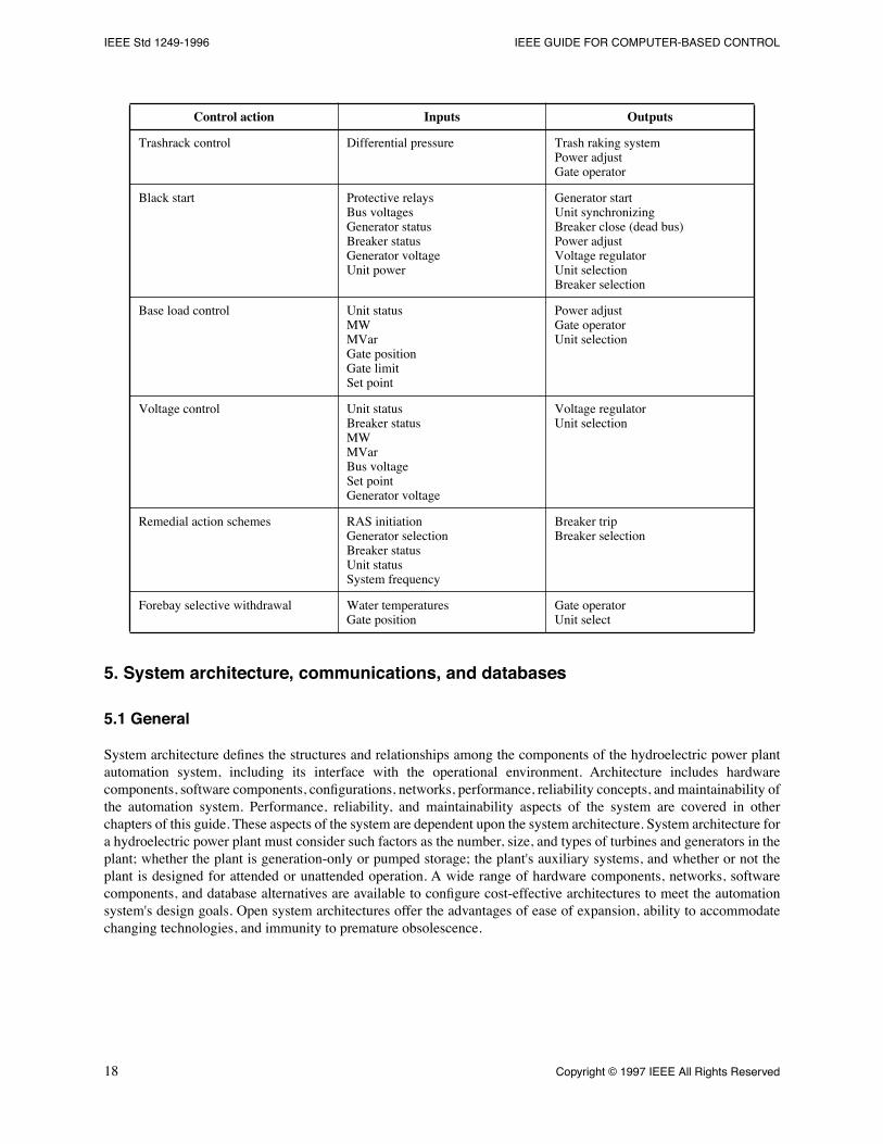
Table 2 gives selected examples of input and output parameters that are necessary to implement some of the computer-based control capabilities discussed in this chapter. This listing is neither complete nor exhaustive, but is merelyillustrative of implementation particulars that should be considered when designing an automation system.
Table 2ÑTypical parameters necessary to implement automated control
Control action Inputs Outputs
Unit Start/Stop Gate limitGate positionBreaker statusGovernor hydraulicsUnit speedUnit protective relaysGenerator voltage
Brake releaseGate operatorCooling water valveExciter Start circuitUnit selectionBreaker trip/close
Unit synchronizing Unit speedGate positionGate limitBreaker statusGenerator voltageBus voltage
IEEE Std 1249-1996 IEEE GUIDE FOR COMPUTER-BASED CONTROL
5. System architecture, communications, and databases
5.1 General
System architecture deÞnes the structures and relationships among the components of the hydroelectric power plantautomation system, including its interface with the operational environment. Architecture includes hardwarecomponents, software components, conÞgurations, networks, performance, reliability concepts, and maintainability ofthe automation system. Performance, reliability, and maintainability aspects of the system are covered in otherchapters of this guide. These aspects of the system are dependent upon the system architecture. System architecture fora hydroelectric power plant must consider such factors as the number, size, and types of turbines and generators in theplant; whether the plant is generation-only or pumped storage; the plant's auxiliary systems, and whether or not theplant is designed for attended or unattended operation. A wide range of hardware components, networks, softwarecomponents, and database alternatives are available to conÞgure cost-effective architectures to meet the automationsystem's design goals. Open system architectures offer the advantages of ease of expansion, ability to accommodatechanging technologies, and immunity to premature obsolescence.
Trashrack control Differential pressure Trash raking systemPower adjustGate operator
Black start Protective relaysBus voltagesGenerator statusBreaker statusGenerator voltageUnit power
Generator startUnit synchronizingBreaker close (dead bus)Power adjustVoltage regulatorUnit selectionBreaker selection
Base load control Unit statusMWMVarGate positionGate limitSet point
Power adjustGate operatorUnit selection
Voltage control Unit statusBreaker statusMWMVarBus voltageSet pointGenerator voltage
Voltage regulatorUnit selection
Remedial action schemes RAS initiationGenerator selectionBreaker statusUnit statusSystem frequency
Breaker tripBreaker selection
Forebay selective withdrawal Water temperaturesGate position
FOR HYDROELECTRIC POWER PLANT AUTOMATION IEEE Std 1249-1996
5.2 System classification
5.2.1 Overview
Advances in computer technology provide a user with the choice of a variety of system architectures for conÞguringhydroelectric automation systems. No attempt has been made to describe all conÞgurations and systems available, butrather to focus on systems currently employed or envisioned to Þnd future use in hydroelectric plant automationapplications.
There are two general classes of system architectures used in hydroelectric plant automation systems. One class ofsystems uses proprietary hardware and software, and makes little or no provision for interoperation with otherhardware and software. For discussion purposes, these are termed closed systems.
The other general system class is an integrated system, with all plant control and monitoring components having acommon data communication structure supported by common hardware and software structures. The trend in thesecontrol systems is towards open systems. From a practical sense, open systems or the openness of a system relates tothe ability to replace hardware, modify software, and expand system capabilities without a wholesale reconÞgurationof the control system. Attributes of open systems are interconnectivity of the hardware and software, portability of thesoftware, and interoperability of applications and systems.
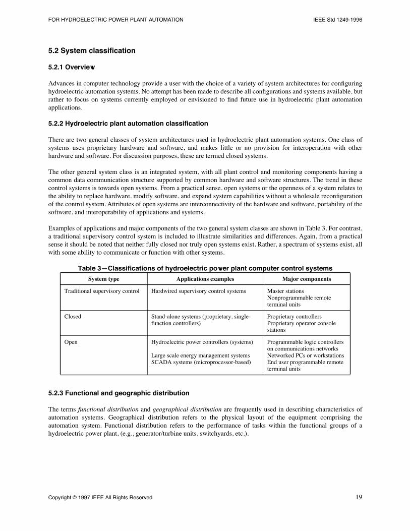
Examples of applications and major components of the two general system classes are shown in Table 3. For contrast,a traditional supervisory control system is included to illustrate similarities and differences. Again, from a practicalsense it should be noted that neither fully closed nor truly open systems exist. Rather, a spectrum of systems exist, allwith some ability to communicate or function with other systems.
Table 3ÑClassifications of hydroelectric power plant computer control systems
5.2.3 Functional and geographic distribution
The terms functional distribution and geographical distribution are frequently used in describing characteristics ofautomation systems. Geographical distribution refers to the physical layout of the equipment comprising theautomation system. Functional distribution refers to the performance of tasks within the functional groups of ahydroelectric power plant, (e.g., generator/turbine units, switchyards, etc.).
System type Applications examples Major components
Traditional supervisory control Hardwired supervisory control systems Master stationsNonprogrammable remote terminal units
Closed Stand-alone systems (proprietary, single-function controllers)
IEEE Std 1249-1996 IEEE GUIDE FOR COMPUTER-BASED CONTROL
5.3 System architecture characteristics
5.3.1 General
Any discussion of characteristics of system architectures for hydroelectric automation systems requires some basicunderstanding of the data communication structures (and related standards) that allow communication betweencomputers. A communication network is the system that permits the linking of resources so information can be passedto where it is needed.
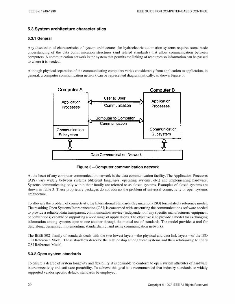
Although physical separation of the communicating computers varies considerably from application to application, ingeneral, a computer communication network can be represented diagrammatically, as shown Figure 3.
Figure 3ÑComputer communication network
At the heart of any computer communication network is the data communication facility. The Application Processes(APs) vary widely between systems (different languages, operating systems, etc.) and implementing hardware.Systems communicating only within their family are referred to as closed systems. Examples of closed systems areshown in Table 3. These proprietary packages do not address the problem of universal-connectivity or open systemsarchitecture.
To alleviate the problem of connectivity, the International Standards Organization (ISO) formulated a reference model.The resulting Open Systems Interconnection (OSI) is concerned with structuring the communications software neededto provide a reliable, data transparent, communication service (independent of any speciÞc manufacturers' equipmentor conventions) capable of supporting a wide range of applications. The objective is to provide a model for exchanginginformation among systems open to one another through the mutual use of standards. The model provides a tool fordescribing, designing, implementing, standardizing, and using communication networks.
The IEEE 802 family of standards deals with the two lowest layersÑthe physical and data link layersÑof the ISOOSI Reference Model. These standards describe the relationship among these systems and their relationship to ISO'sOSI Reference Model.
5.3.2 Open system standards
To ensure a degree of system longevity and ßexibility, it is desirable to conform to open system attributes of hardwareinterconnectivity and software portability. To achieve this goal it is recommended that industry standards or widelysupported vendor speciÞc defacto standards be employed.
FOR HYDROELECTRIC POWER PLANT AUTOMATION IEEE Std 1249-1996
Hardware interconnectivity standards apply to system backplane and peripheral connection standards. As an example,typical backplane standards are VME Bus (IEEE Std 1014-1987), and EISA Bus (defacto standard). Peripheralconnection standards are broken into two broad groups, parallel and serial. An example of a typical parallel connectionstandard is the Small Computer System Interface (SCSI); a typical serial connection standard is the TIA/EIA series ofstandards RS232, RS422 and RS485 (industry standards).
Software portability relates to the operating systems, programming languages, and user interfaces with thehydroelectric automation system. Ideally, the hydroelectric automation software should be capable of being movedfrom one vendor's hardware to another, if required, although this ideal is yet to be realized. Standards (industry anddefacto) promoted by the Open Software Foundation focus on software portability issues. Examples of standards inthis area include the IEEE Portable Operating System Interface Standards (POSIX¨) Series, OSF/DCE (DistributedComputing Environment), and Motif (window management environment defacto standards).
An implementation of the OSI reference model applicable to communications within electric utilities is the UtilityCommunications Architecture (UCA), under development by the Electric Power Research Institute (EPRI), in the U.S.UCA speciÞes a standard for each layer of the OSI reference model and references a set of implementer's agreements,developed by users and implementers of OSI products, to assure interoperability of applications and systems. Work isunderway to address the need for utility-speciÞc implementer's agreements for the use of the Manufacturing MessageSpeciÞcation (MMS), which is used within UCA for control and data acquisition applications."
5.3.3 Networking and communication considerations
5.3.3.1 General
The two lowest layers of the OSI reference model are the physical layer and the data link layer. For communication tohigher layers within the OSI reference model (for example, to a utility area-wide control system from a hydroelectricplant automation system), the next layerÑthe communications layerÑmay be involved.
5.3.3.2 Communications and network layer considerations
Availability and successful operation of the data communication network is essential to the reliability of ahydroelectric automation system. There are a number of important concepts to evaluate when considering acommunication data network for a hydroelectric power plant data acquisition and control system, some of which areas follows:
a) Data links. Communication among major system elements should use bit serial communication links.b) Adherence to industry standards. The data network should conform to formal and informal (de facto) industry
standards to provide for the widest selection of mutually compatible equipment, and ensure long service life.c) Availability. The data network should be designed for maximum availability. This will require fault tolerant
design concepts and possibly even a redundant network.d) Correct operation. The data network should, as a minimum, use error detection techniques to prevent the
acceptance and use of corrupted data. Error detection without correction implies either loss of the data for thereporting cycle, or a request for retransmission of the data.
e) Data transmission speeds. The data system design should consider the amount and type of data to betransmitted, and the time constraints on the data, e.g., time sensitive control algorithms. Time constraintsinclude consideration of worst case data transmission activity such as complete update of a plant data baseduring a period of maximum control system activity after a control system element failure, a plant equipmentfailure, a power system disturbance, or a combination of these events.
f) Environmental considerations. The control data network system should operate acceptably in the expectedoperating environment. The equipment may be subjected to electromagnetic interference (EMI), radiofrequency interference (RFI), and temperature and humidity changes. Data networks with physically longpaths may have ground potential differences between terminals of the network during fault conditions.
IEEE Std 1249-1996 IEEE GUIDE FOR COMPUTER-BASED CONTROL
g) Data network operation. There are several network control protocols to consider in the design of a datanetwork. Each has advantages and disadvantages to be compared and evaluated considering the volume ofdata expected, the response time necessary, and achievement of simple system operation.
h) Offsite data communications. The design of the offsite data communication links should accommodate thetype and volume of data to be transmitted and received, and the communication facilities available to carrythe data. Industry standards should be followed, allowing the use of widely available and compatibleequipment.
5.3.3.3 Data communication functions
5.3.3.3.1 Monitoring and control
Monitoring equipment. In a digital control system, data from monitored equipment travels over the communicationlink (or links) to the data acquisition and control system node requiring the data.
Data from the controlled equipment is in one of two forms: discrete data such as contact positions representing alarmsand/or events, switch positions, or equipment status; and continuously variable (analog) data. Discrete data is used asequipment status information for operating programs, operator interface display programs, and can optionally be usedfor sequence of events (SOE) recording. Discrete data may also include information from position encoders,transformer load tap changing equipment, and contact closure or pulse inputs from watthour measuring instruments.
Analog data is sensed at the process interface, converted to a digital representation of its analog value, time tagged, andplaced in the data base of the control system node where it is sensed. Analog data can be used to generate alarms. Arate of change greater than a reasonable value or a value beyond acceptable limits for the equipment can be used togenerate alarms, with the analog data time tag providing time of occurrence information.
Controlling. In a digital control system, control action can be initiated either as a result of application program resultswithin the control node near the controlled equipment (the local node), or by action of the station control node. If thelocal node initiates control action, the communication network is not used. If the control action is initiated by theoperator via the operator interface, or by the station control node, the communication network is used.
Typical control actions in a hydroelectric plant result in starting and stopping turbine-generator units, closing circuitbreakers, controlling unit load and generator voltage, opening and closing spillway gates, and operating auxiliaryequipment, including station service breakers and transformer tap changers. Control actions are initiated at theoperator interface or by the station control node, transmitting the control command to the local node over thecommunication network.
5.3.3.3.2 Control node configuration and initialization
The system control nodes' application programming may include both software and Þrmware, and the controlprogramming may use proportional, integral, and derivative (PID) and other control algorithms.
The control node conÞguration software, or the PID loop parameters, should not be accessible to change by all usersof the control system. There should be a system security provision permitting alteration of the software only by thoseauthorized. An automatic audit trail should exist documenting the changes and their implementer.
5.3.3.4 Control data communication requirements
5.3.3.4.1 General
The control data communication network requirements include: time constraints; dependability; safety; datacommunication network transparency; diagnostics; and maintenance. The following discussion applies mainly todistributed types of control systems with their various nodes connected by one or more communication networks. It isapplicable to closed systems insofar as these systems use data communication networks among their various elements.
FOR HYDROELECTRIC POWER PLANT AUTOMATION IEEE Std 1249-1996
5.3.3.4.2 Time constraints
5.3.3.4.2.1 Process data availability
Ideally, the current value of the data from each process input, analog or discrete, should be instantaneously availableto the requesting application program. In practice, delays between the time the data appears at the process inputterminals and the time it appears in the plant data base are unavoidable.
5.3.3.4.2.2 Data transport delays
There are a number of sources of data delay. For a digital control system, the Þrst delay occurs in transmitting processdata from the input terminals to the data base of the system control node nearest the controlled process (the local node).For analog data, the Þltering and a/d conversion process introduce the Þrst delay. For discrete inputs, the scan processis the Þrst, and usually least important, (apart from the contact bounce Þlter), source of delay. If the local nodeperforms closed loop control, other delays in data transmission become less important, or less critical to the localcontrol process.
Another delay occurs between the local node and any other node utilizing this data. This delay includes time to formatthe data for use by the communication network, time to queue the data for transmission and time for the local node toexecute the data communication system transmission protocol and transmit the data.
A source of delay occurs with transmission of data to an offsite control system at a dispatch center. Thecommunication network control protocol used by the network to the offsite system may introduce anotherunpredictable delay.
5.3.3.4.2.3 Control command execution
System security requires error-free, correct performance of control actions, e.g., the control command must not bemisinterpreted by the local control node. Rather than chance incorrect control operation, it is better to reject thecommand, and ask for it to be repeated, or wait for the next command. To achieve this security level, sophisticatederror detecting codes are used, as well as automatic checkback to verify command validity.
If checkback before operation is used, the effective transmission time of the control command is more than doubled.The transmission time may be unpredictable because if the intended receiving node is transmitting data at the time acommand is sent, there is a delay in its command retransmission for veriÞcation. If the control command sequencerequires a checkback veriÞcation, further delays are introduced.
5.3.3.4.2.4 Overall control system delays
Power plant response to offsite control commands such as AGC inputs requires accounting for the amount and type ofplant data used by the offsite system to determine its control requirement for the plant. Delay in transmission of datato the offsite system from the plant data base is the sum of all delays in getting the data from the local node to the plantdata base node.
5.3.3.4.3 Dependability
Data communication network dependability is a broad term covering hardware reliability and availability, datatransmission error detection and correction, and software reliability. For critical systems, redundant datacommunication networks and/or other fault-tolerant design features may be required. Fault-tolerant data networksshould be designed so that failure of any single element of the data network does not cause the entire network to fail.The hardware should exhibit excellent availability and be capable of being quickly repaired and returned to serviceafter a failure.
IEEE Std 1249-1996 IEEE GUIDE FOR COMPUTER-BASED CONTROL
Data errors due to noise or other inßuences on the transmission medium must be detected and corrected if possible, orthe data must be quickly retransmitted. Excessive errors will increase data transmission times, and lead to problemsassociated with inadequate transmission network capability.
5.3.4 Safety
Plant, equipment, and personnel safety require the control system to not issue, or permit execution of, an incorrectcommand caused by data errors or equipment failure. To achieve safe operation, the data network must be reliable andhave error detection capabilities. Each network topology (see discussion in 5.4.2) has its own set of pros and consregarding safety issues. There are a number of techniques used to assure reliable data communication regardless of thenetwork topology used. If a speciÞc data communication link fails, it should not cause failure of the entire datacommunication network. The system should be able to automatically reconÞgure itself and continue transmission ofdata to remaining operable components. Critical data that are required for life or plant safety systems (e.g., damspillway gates, etc.) should receive priority in reconÞguration schemes.
5.3.4.1 Data network transparency
Data network operations should be transparent to plant operators and to equipment outside the terminals of the datanetwork. All data transmission functions, including error detection and correction, formatting for transmission, andpreparation for presentation to control system nodes should be done by the data network equipment without attentionfrom the control system nodes.
5.3.4.2 Diagnostics
The data communications network should include diagnostic software for both online and ofßine functions. Monitoredonline functions include data network performance and alarming for excessive channel errors and channel failures.Ofßine functions should include tests of each hardware element of the system, transmission medium tests, andveriÞcation of the data network error detection and correction features.
5.3.4.3 Maintenance
The data communications network should be easy to maintain, preferably without interruption of the data transmissionfunction. Completely redundant, independent data networks are desirable, so the control system remains operable ifone of the networks fails. Further, a failure of a single element should not precipitate a total system failure.Redundancy provides a means for effecting system repairs and provides a method for system tests or training.
5.4 Control data networks
5.4.1 General
There are two general classes of control data networks Þnding application in hydroelectric automation systems.Both are Local Area Networks (LANs), one being conÞgured to a set of IEEE Standards (IEEE 802 series) withthe IEEE 802.3 (Ethernet) standard Þnding widescale application in hydroelectric automation systems. Two otherstandards from the IEEE Series (802.4 and 802.5) involving token passing protocols likewise Þnd application inthese same systems. A second category of networks covers a broad range of proprietary bus topologies. Proprietarytopologies Þnd application in both segregated and integrated systems. This clause brießy discusses features of thetwo classes of control data networks.
FOR HYDROELECTRIC POWER PLANT AUTOMATION IEEE Std 1249-1996
5.4.2 Local area network (LAN) topologies
5.4.2.1 General
The local area network differs from a conventional multi-point data network in several signiÞcant ways. With a multi-point data link, a computer typically communicates with a number of relatively simple terminals. Communication iscontrolled by the computer, and transmission occurs only between the terminals and the computer at relatively slowspeeds. With a LAN, each device attached to the communication medium is a relatively intelligent machine, and anydevice attached to the LAN can communicate with any other device on the network at very high speed. Figure 4contrasts the physical differences between multi-point data links and local area networks.
Figure 4ÑMulti-point data link versus LANs
5.4.2.2 LAN characteristics
¾ Station Relationships. With a typical LAN, all stations accessing the common communication facility arepeers on the network; there is generally no distinction made between primary stations and secondary stations.
¾ Message Exchange. A LAN is designed to give the appearance of supporting multiple message exchanges atany given time between various pairs of stations, although in actual practice only a single message can betransmitted at any given instant.
¾ Transmission Speed. Transmission speeds are very high, typically in the millions of bits per second.¾ Distance. A LAN is designed to support communication over a limited geographic area, for example within
a powerhouse or control dispatch center.¾ Transmission Medium. A LAN typically uses private, user-installed wiring as the communication medium.¾ Extensibility. A LAN is designed to transparently become part of a wide area network (WAN). This allows
IEEE Std 1249-1996 IEEE GUIDE FOR COMPUTER-BASED CONTROL
5.4.2.3 Classifications of local area networks
Many hardware and software systems are available for implementing local area networks. All share the generalcharacteristics just discussed but all are implemented in different ways. In general, LANs are classiÞed according tothe following criteria:
a) Network topologies;b) Transmission media;c) Transmission techniques;d) Access protocols.
5.4.2.4 Network topology classification
5.4.2.4.1 General
The network topology relates to the logical way in which stations are interconnected. The three major topologies arethe ring, the star, and the bus, described in 5.4.2.4.2Ð5.4.2.4.4.
5.4.2.4.2 Star topology
With the star topology (see Figure 5), all stations are connected through a central control point. The Multipoint DataLink shown in Figure 4 is an example of a star topology. True star topologies are seldom used in modern networks.TokenRing and 10BASE-T Ethernet use cabling schemes that resemble a star topology. However, TokenRing iselectrically a ring topology, and 10BASE-T Ethernet is electrically a bus topology.
Figure 5ÑStar topology
5.4.2.4.3 Ring topology
With a ring, (see Figure 6), each station is connected to the next one to form a closed loop. Each station has atransmitter and receiver, and data is transmitted in one direction around the ring. In a regular ring conÞguration, thecommunication media is connected point-to-point to each node, with each node acting as a repeater. The arrangementprecludes bidirectional communication since the transmitter of one node is connected to the receiver of the next node.This characteristic makes the ring topology favorable for Þber optic media, a unidirectional communication medium.Token Ring topologies are covered in ISO/IEC 8802-5:1995, and Þnd application in hydroelectric automation systems.
FOR HYDROELECTRIC POWER PLANT AUTOMATION IEEE Std 1249-1996
Figure 6ÑRing topology
5.4.2.4.4 Bus topology
With a bus (see Figure 7), all stations are attached to a single cable. Standard and ThinNet Ethernet, 10BASE5, and10BASE2 are examples of a bus topology.
Figure 7ÑBus topology
5.4.2.4.5 Topologies employed in hydroelectric automation systems
Topologies employed in closed hydroelectric automation systems are usually based on manufacturer's proprietarysystems (for a discussion of backplane standards, see 5.3.2). General characteristics of typical proprietary systems aredescribed in 5.4.2.6. Bus, ring, and star topologies all Þnd application in control systems. A cursory comparison ofcommunication data networks employed with hydroelectric automation systems is shown in Table 4.
IEEE Std 1249-1996 IEEE GUIDE FOR COMPUTER-BASED CONTROL
Table 4ÑHydroplant computer control systems data communications attributes
5.4.2.4.6 Proprietary bus topologies
Some digital control system vendors provide proprietary data links for equipment modules of their own make. Somemay provide complete systems, with process I/O devices and controllers included on the proprietary network data link.Most, however, provide a standard gateway to interface their proprietary data link to an industry standard such as ISO/IEC 8802-3:1996 (Ethernet), a Manufacturing Automation Protocol (MAP) network, or other protocols developed byother standards writing entities (ISA, DOD, etc.).
Proprietary data communication networks (and in some cases, bus structures) are used with some closed controlsystems having dispersed elements. Normally, for these closed control systems, the user will not have to be concernedwith the network capability; the vendor will have ensured that all elements are working together to provide thenecessary performance. However, should the closed system be of a new design with no performance record, the usershould verify that the data communication network has the design capacity to perform as speciÞed, and obtainperformance guarantees from the vendor.
If the closed control system requires communication with another system in the plant, the design must have provisionsto ensure that the proprietary data communication network can interface with other systems, either through a bridge ora gateway. For the interface arrangement, data transmission speed will be a consideration.
Proprietary data communication network protocol may be a factor in reusing existing remote terminal units (RTUs)when partially replacing or expanding an existing control system. Older systems almost invariably used proprietarydata formatting and communication protocol. In this instance, it will probably be necessary to use a gateway betweenthe two systems.
A further discussion of proprietary control systems and data communication networks may be found inIEEE Std 1046-1991.
5.4.3 Physical transmission media
Media types used to implement network topologies include unshielded twisted pair, shielded multiple twisted pair,coaxial cable, twin axial cable, or Þber optic cable. The choice of media for a hydroelectric automation applicationdepends on isolation characteristics, transmission bandwidth, signal attenuation, access methods, cost, and immunityto noise. The installation methods used with metallic media have a signiÞcant inßuence on the immunity of circuits tonoise (e.g., use of cable trays dedicated only to control cables will signiÞcantly increase the immunity to noise of theaffected circuits). Table 5 provides a relative comparison of some critical parameters of the various media. It should benoted that the cost of Þber optic cable and equipment is dropping, relative to other physical transmission media. Thegenerally superior characteristics of Þber optics combined with its dielectric isolation make Þber optics well suited forapplication in power plant control systems.
Traditional supervisory control Central computer (master) communicating with nonprogrammable RTUs over wire, fiber, radio or microwave; dedicated communications channels Star topology
Closed Small scale systemsProprietary networksProprietary communications links
Open Unlimited scale systemsOpen system architectures(IEEE 802 series networks)
FOR HYDROELECTRIC POWER PLANT AUTOMATION IEEE Std 1249-1996
Table 5ÑCable media characteristics
5.5 Data bases and software configuration
5.5.1 Open systems and data bases
As open systems become a more popular choice for a control system architecture in the hydroelectric plant controlsystem industry, database management systems have become the subject of more intensive study. Formerly, databasesystems were a givenÑthey came with the system, were vendor proprietary, and could not be interfaced with softwarefrom other vendors.
There are four main types of database management systems, which are distinguished by the way they organize data.The data organizations are hierarchical, network, relational, and object-oriented.
a) Hierarchical. In a hierarchical database, the relationships between records are extremely limited. If a moreextensive (network) relationship is required for an application, then the application has to manage therelationships through programmatic manipulations, leading to a system that is very difÞcult to maintain.
b) Network. In a network database, any record can be related to any other record. The network model permitscomplex connections among data at extremely high efÞciency while supporting a high volume of users. Theperformance of a network database is dependent upon the identiÞcation and organization of relationshipsduring the design process. The network model is particularly inßexible in terms of permitting changes afterthe initial design.
c) Relational. The relational model implements relationships between data as occurrences of rows, columns andtables. New Þelds and modiÞcations to the initial database can be accomplished with a minimum ofrestructuring. Relationships among record types are established dynamically, permitting new applications tobe easily accommodated. The relational model has the beneÞt of being associated with a Þrm theoreticaldescription.
d) Object-oriented. This database design is an emerging technology that is growing to Þll the deÞciencies of therelational model. Object-oriented databases permits data to be shared externally during database execution,providing excellent speed and simplicity. The object-oriented database lacks the Þrm theoretical base that therelational model possesses.
5.5.2 Real-time vs. nonreal-time database designs
Hydroelectric automation systems require both real-time and nonreal-time database designs. Real-time designs mustbe capable of supporting database access requirements of the user interface (UI), SCADA, automatic generationcontrol, event recording, etc. These tasks all must be accomplished in several milliseconds.
Nonreal-time database designs are needed to support historical functions, trending, reporting, and other non-real-timerequirements. These functions require massive amounts of data processing that usually dictates a design at odds withreal-time requirements.
Unfortunately, commercially available databases have been inadequate to meet the real-time needs of the automationsystem and power systems environment. This has forced vendors to develop highly specialized proprietary databasesto link with a very limited set of external hardware and operating systems. These systems can accurately be describedas closed systems preventing interface with other hardware and software. Any expansion or modiÞcation of the systemmust be referred to the original vendor or one must develop in-house expertise to perform the changes desired.
Cable type Noise immunity Transmission speed Transmission length
IEEE Std 1249-1996 IEEE GUIDE FOR COMPUTER-BASED CONTROL
While automation system vendors must rely on their proprietary database designs to satisfy real-time demands, thereis an increasing movement to incorporate commercially available databases to provide nonreal-time functionality.Reporting, trending, maintenance scheduling and other ofßine functions can be very adequately provided by populardatabase designs that provide a broad range of user deÞned characteristics and interfaces.
Often it is possible to retroÞt a relational database to an existing system to provide user deÞned ßexibility in reportingand other management tasks. When designing the linkage between the nonreal-time commercial database and theautomation system vendor's proprietary database, data transfer in both directions must be included.
The beneÞts of using commercially-available database management systems include the following:
a) Direct linkages to supporting relational database information is available;b) Plant operation data is available (through a utility's wide area network) to other groups within the operating
utility;c) Reporting formats can be easily changed to meet changes in plant operational documentation.
5.5.3 Software configuration
5.5.3.1 Custom software
In the custom software area there are several options, as follows:
a) Dedicated. The software changes are closed to the end user.b) ConÞgurable. The software has features that can be changed by the user's software maintenance personnel.
These changes are normally of the form of turning on or off a feature that is already in the software througha software key or password.
c) Programmable. The software has features that can be changed or added by the user's software maintenancepersonnel.
5.5.3.2 Commercially-available software
The custom software described in the previous clause is normally available only as part of a turnkey automationsystem. In contrast, commercially available software can usually be purchased as part of a turnkey system or directlyby the power plant owner. In the latter case, the owner will have to make provisions for the installation andconÞguration of the software. Spreadsheets, database managers, and operator interface software packages are allexamples of commercially-available software being used as part of the power plant automation system.
Commercially-available software provides ßexibility and has many options. Because of its availability, the user hassupport from not only the original vendor, but other users and possibly other vendors. The most common options areas follows:
a) User conÞgurable. The user has all of the documentation necessary to change the software operation or to addnew code that is linkable to the rest of the software. The user has the ability to add features or change options,but cannot change features in the original code without the aid of the original vendor.
b) User programmable. The user has the source code as well as the documentation for the software and canmodify it as needed using internal staff or any contractor the user wishes, or the user can implement his/herown software to be added to the system.
c) Full graphics. The user has the ability to generate pixel and/or vector graphic images on the displays in anyform. The software has sophisticated artwork generation and real-time display of these images under systemcontrol. Often, full graphics are implemented in a windowing operating environment.
d) Online conÞgurable. The features mentioned above can be done by authorized personnel sitting in front of theonline and running system. That is, authorized personnel can change the conÞguration of the running systemas they wish.
FOR HYDROELECTRIC POWER PLANT AUTOMATION IEEE Std 1249-1996
6. User and plant interfaces
6.1 User interfaces
The most critical interface for a power plant automation system is the User Interface (UI). The plant interfacesdiscussed later in this clause are important to the automation system in order to perform effective monitoring,annunciation, control, etc., but the UI is crucial to the success of the system. If the operator is not able to use the systemeasily and conveniently, the system will never be used properly or cost effectively. The operator's needs are critical tothe successful operation and use of a power plant automation project. UIs offering the look and feel of a personalcomputer may be desirable to reduce special training.
In order to make the system acceptable to the operations personnel, care must be taken in the selection of the hardwareand software used. The hardware options are numerous for both input and output devices as well as the workstationsto be used.
6.1.1 Input devices
Input devices are not mutually exclusive and may be combined to incorporate desired features. Typical devices includethe following:
a) Trackballs. Pointing devices for menu driven software. Trackballs are normally used in conjunction with astandard ASCII keyboard and/or numeric keypad and occupy very little desktop space.
b) Mice. Similar to track balls, they are normally used in conjunction with an ASCII keyboard and/or numerickeypad. A mouse requires more desktop space than a trackball since the mouse must be moved in order tomove the cursor on the screen.
c) Light pens. A pointing device for menu-driven software. Light pens normally use an ASCII keyboard and/ora numeric keypad for data entry and require no desktop space.
d) Keyboards. Normally installed on all workstations for data input and system control. Desirable features forkeyboards and numeric keypads include standard key layouts and tactile feedback. They need to be wellconstructed to withstand continuous use. They should be waterproof and dustproof. Keyboards using layoutssimilar to the familiar PC will minimize the chance for confusion arising from the use of a nonstandardkeyboard.
e) Touch screens. Useful for cursor positioning but not well suited for data entry.f) Speech recognition. This input technique is a leading edge technology. It has many disadvantages at present
such as speaker dependency, large error or misinterpretation rates, large memory needs, and extensiveprocessing time.
6.1.2 Output devices
As with input devices, various output devices may be combined to incorporate desired features. Some typical devicesare as follows:
a) Printers. These devices range from dot matrix units to letter-quality line printers in both black and black-plus-color models. They are used for hard copy output of the computer data for reports or historical records.
b) CRT screens. These output devices are on most UI systems and are the primary output device for thecomputer. They range from small monochrome units to large color units with millions of color combinations.
c) Speech synthesis. Provides the operator with a phonetically-based audible message output.d) Mimic boards. Graphical displays or map boards used to represent the conÞguration and data of the plant or
system. Mature technology units range from manual displays with movable parts to Þxed displays with lightsto indicate equipment status. New technology units include displays of system data in graphical form andlarge projection screens with computer generated displays.
IEEE Std 1249-1996 IEEE GUIDE FOR COMPUTER-BASED CONTROL
6.2 Plant interfaces
The plant to computer-based control system interfaces are important to the success of the automated hydroelectricpower plant's control system. There are many types of hardware interfaces, each with speciÞc requirements that mustbe addressed as the system is designed, installed, and tested.
6.2.1 Types
Examples of plant interfaces include analog transducer signals, dry contacts (i.e., contacts without sensing voltages)and digital data. This clause covers several generic types, but the coverage is not complete because installations mayhave special application requirements to meet unique concerns. This discussion addresses the analysis process for anyplant interface.
6.2.1.1 Digital, contact, and pulse inputs
Digital or contact inputs should meet minimum criteria for operations at the voltages and current loads anticipated.The current required to drive the input circuitry should be adequate to ensure false indication changes do not occur dueto noise. The current should be as low as possible to conserve power and reduce heat generation. Wetting voltages(e.g., those voltages required to sense the status of dry contacts) may be provided by the control system or the Þelddevice.
Contact bounce in the input signal can cause erroneous data in the system. Digital inputs should have Þlters to detectonly sustained input signals. These Þlters may be in the hardware or the software. Filters must be selected inaccordance with time tag accuracy. Simple low-pass Þlters can introduce undesirable delays. Voltage levels for logicdetection should be sufÞcient to prevent erroneous readings.
Digital inputs may also serve the functions of pulse accumulators or counters. This function is normally in software orÞrmware at the I/O. Accuracy, counting, and pulse accumulation rates should be sufÞcient for the intended use.
Another variety of digital inputs comes in the form of a parallel (e.g., binary coded decimal) data. The quantity of wireconductors, noise immunity, and hand shaking requirements should be considered when making accommodations forthese inputs.
Serial digital inputs (e.g., EIA RS232, RS422) are frequently used as an interface to newer transducers. Considerationsfor interfacing with such inputs are covered with other communications issues in 7.3.
Digital input status indicators, often LEDs, may be provided. These indicators ease I/O and control circuittroubleshooting.
6.2.1.2 Digital and contact outputs
Digital or Contact outputs provide data and control contacts for external circuits. These contacts must have sufÞcientcurrent and voltage rating for the external load. These ratings must often be considered in total for a given card orgroup of I/O as well as for individual circuits. Wetting voltage is typically provided by the external circuit. The abilityof the solid-state devices in the output circuitry of the I/O to absorb the required current (without thermal instability ofthe devices) is a function of temperature (heat generation).
Where higher current ratings are required, interposing relays are typically installed. The current ratings are then thoseof the interposing relays.
Digital outputs may be latched, momentary, or maintained. These functions may be implemented in software or in theoutput relay. Digital output status indicatorsÑusually LEDsÑmay be provided, similar to those on input I/Os.
The failure state of digital outputs should be deÞned and speciÞed. Digital output failure may be critical in someapplications.
FOR HYDROELECTRIC POWER PLANT AUTOMATION IEEE Std 1249-1996
6.2.1.3 Analog inputs
Analog inputs may be low-level (e.g., 0Ð1 mA dc, 4Ð20 mA dc, 1Ð5 V dc, etc.) current or voltage, resistance, orthermocouple signals. Resistance or millivolt (thermocouple) inputs may be scaled to engineering units by the I/Oprocessor, or a separate RTD or thermocouple to current or voltage converter located with the I/O.
The I/O is often capable of providing the loop power supply for analog inputs. Voltage, tolerance, stability, and loadingshould be considered.
Scaling accuracy, resolution, deadband, and thermal stability should all be speciÞed to meet the needs of theapplications. Thermocouple and RTD replications should meet the standard accuracy for these devices. Openthermocouple detection is often desirable. Common and differential mode rejection ratios should also be speciÞed.
When multiplexing technology is used, the multiplexing hardware should be solid-state and not electromechanical.Multiplexing schemes must be fast enough to ensure that the most recent values are available when required for allcontrol loops.
6.2.1.4 Analog outputs
Analog outputs are typically low-level voltage or current. Accuracy, resolution, deadband, and thermal stability shouldall be speciÞed. Similar to digital outputs, the condition or value of analog outputs upon failure may be critical in someapplications.
The accuracy of any analog input or output depends on the conversion between the computer's digital data system andthe analog information. The conversion is typically performed by multi-bit A/D converters. Conversion accuracy andresolution are a function of the number of A/D converter bits and I/O ampliÞer design. Further, the accuracy is affectedby temperature-induced drift. Thus, A/D resolution, input accuracy, and temperature stability should all be speciÞed.
6.2.1.6 Field devices and field bus standards
Another major source of interface signals are those originating from intelligent electronic devices (IED) and intelligentÞeld devices (e.g., a Þeld device capable of measuring more than one parameter and transmitting the measuredparameters over one pair of wires). Intelligent Þeld devices and Þeld bus systems are a developing set of speciÞcationsenabling replacement of the traditional 4Ð20 mA instrument communication system and associated devices whileretaining the existing instrument wiring. The resulting reduction in Þeld devices and the sharing of wiring reducesinstallation costs. Standards covering intelligent Þeld devices and Þeld bus systems are developed by several standardsorganizations including IEEE, International Electrotechnical Commission (IEC), Instrument Society of America(ISA), and National Electrical Manufacturers Association (NEMA). IEEE P1379/D5 is applicable to multipoint datacommunications between IEDs and RTUs in utility substations. A commonly used Þeld bus standard is ISA SP50. Anumber of proprietary and de facto standards also Þnd widespread use.
6.2.2 Sources
The sources of information to be interfaced to control systems are numerous and not all are covered in this clause. Themost common ones are highlighted, as follows:
a) Digital Input Signal Monitoring. Usually accomplished by sensing the state of relay contacts using the stationbattery or a voltage supply to detect the opened or closed status of the contact. The output devices arenormally solid-state or electromechanical relays that are energized or de-energized by the control system.
b) Analog Input Devices. Normally transducers that convert potential transformer (PT) and current transformer(CT) signals to quantities such as megawatts or megavars. In existing plants, control system analog outputsmay drive display panels or strip chart recorders for operator observation.
IEEE Std 1249-1996 IEEE GUIDE FOR COMPUTER-BASED CONTROL
c) Parallel Input Devices. Usually shaft encoders or digital panel meters. The output devices are digital panelmeters or process controller modules. These interface sources are in many cases bidirectional, i.e., they areboth input and output devices. Typically, these devices use a Binary Coded Decimal (BCD) encoding scheme,and range from a 4-bit wide (1 BCD digit) bus to 32-bit wide (8 BCD digits) bus, plus control lines.
d) Serial Sources. Normally bidirectional devices with built-in intelligence, providing both input and outputcapability. The devices consist of smart watthour meters, shaft encoders, temperature transducers, etc.
6.2.3 Input/output protection
All inputs and outputs should be speciÞed to withstand the Surge Withstand Capability (SWC) test, as described inIEEE C37.90.1-1989, without any false operations. The SWC test has proven to be a reliable means to identify noiseproblems similar to those found in a hydroelectric powerhouse. Other test considerations, such as RFI, are covered in10.1.1.
6.2.4 Collection process
The data collection process involves all of the aspects discussed above as well as some considerations that are internalto the control system as opposed to the interface itself.
6.2.4.1 Scan rate
The scan rate deals with the rate at which the data is moved from the interface to the database, or from the database tothe interface.
6.2.4.2 Archival rate
The archival rate of the control system is normally the rate at which data is stored for long-term, historical purposes.This rate varies dependent on data type, in order to save storage space, retrieval time, and analysis efforts. For example,the archival rate for temperature data does not need to be as often as that for electrical data.
7. System performance
7.1 General
Performance of the control system may be judged in terms of hardware performance and software performance. Thereare situations where the boundaries between these two are not clear. In addition, software performance often dependson the performance of the hardware system on which it is operating. Software performance is evaluated by overallsystem performance. This clause discusses hardware performance and the performance of the overall system. Systemperformance is based on the following four criteria:
a) Security. The ability of the system to prevent unintended operations, misinterpreted communications, andcomputational errors. The security of the system is a function of error rates, checking and correction,redundancy, and communications protocols.
b) Reliability. The rate of failure of hardware, system function, and software. Measured as the availability of thesystem.
c) Speed. The rate at which the control system performs functions. This includes response to inputs, operatorcommands, and system events.
d) Input/output integrity. The accuracy of input detection and conversion to internal system units, outputconversion from internal units to output values, input recognition, and time tagging if performed at the input.
FOR HYDROELECTRIC POWER PLANT AUTOMATION IEEE Std 1249-1996
Often these criteria are affected by factors outside the control of the system supplier and are dependent on systemdesign. These may be communications equipment and systems, power supply systems, environmental factors,software, or other items that interface with the system that are provided by the end user or others in the process ofimplementation. Performance criteria must be established for the system and carefully reÞned to govern workprovided by all parties involved with system implementation.
Hydroelectric applications of control systems have their own unique requirements. These range from speciÞc softwareapplications for efÞcient operations, environmental extremes, remoteness from available service personnel andreplacement parts, and unattended operation. Each of these must be taken into account for the speciÞc application andperformance criteria developed. There are a number of mutually exclusive factors that must be recognized andevaluated to determine an optimal solution for the application. Factors to be considered are as follows:
a) Control stability versus responsiveness;b) Robustness versus complexity;c) Accuracy versus tuning difÞculty;d) Capital versus operating and maintenance costs.
In addition, cost must be weighed as a factor in establishing performance requirements in any of these areas. Typically,the higher the performance required of the system, the greater the system complexity, and the greater the cost.
7.2 Hardware
7.2.1 Input/output (I/O) subsystem
Input/output characteristics are critical to the proper operation, installation, reliability, and maintenance ease of thecontrol system. The I/O subsystem provides the protective buffer between the harsh electrical environment of the plantand the electrically sensitive environment of the digital computer.
The input/output subsystem should be able to accurately convert between digital and analog signals in the computersystem, and general plant digital and analog parameters. In addition, the input/output system may perform time-tagging, scaling, and unit conversion functions. Isolation and protection functions are also part of the input/output. I/O devices will be provided with single or multiple processors on the I/O card or board, or within the terminal cabinet.These processors control communications with the host system, and perform input scaling, time-tagging, and unitconversion if resident in the I/O.
Performance considerations for various applications include the following:
a) Portability and the exchange of I/O cards from one I/O location to another. This can reduce spare partsrequirements.
b) Availability of I/O cards to be replaced under power. This avoids the need to shutdown an entire I/O locationto change one card.
c) Sequence-of-Events (SOE) time tagging at the I/O locations; accuracy and resolution.d) Availability of I/O signal types and levels that support the Þeld device signals to be used.e) Support of redundant Þeld devices, capability for redundant I/O from Þeld device to the database and operator
interface.f) I/O diagnostics available at the card, e.g., card failure or I/O failure indicating LEDs, or through software in
the system.
7.2.2 Control processing systems
The control processing system may be made up of a single-chip microcomputer or chip sets supporting single ormultiple microprocessors. These often take the form of dedicated control units (embedded microprocessor),programmable logic controllers, or microcomputers. These processors are the central device in the control system.
IEEE Std 1249-1996 IEEE GUIDE FOR COMPUTER-BASED CONTROL
Considerations in processor performance are processor speed, bus bandwidth, and memory type. These parameterscontrol the speed of operation of the control system. The system performance characteristics discussed later in thisguide are functions of these parameters.
Memory is a critical part of the processing system. Memory may be chip-based or media-based. Media may be Þxedor removable disks, magnetic tape, or CD-ROM. The amount of program and database storage directly affectsprocessing speed and response. The amount of data or archival memory affects the amount of data that can be stored,and to a lesser extent the speed of data storage, trending, reporting, and archiving functions. SufÞcient memory shouldbe provided for the maximum program, database, and data archives anticipated. An additional spare amount above thatis desirable.
Many processing systems operate in a multi-tasking or time-sharing environment. These processors are generally moreresponsive to changes in parameters and control actions. Interrupt-driven systems provide similar response, but mayhave slower, lower-priority processes. Generally, control processes and actions are assigned levels of priority thatdictate the frequency and priority over other functions.
Other considerations fundamental to system performance are:
a) Response to loss of power. Loss of memory or program is signiÞcant on loss of power. This governs restarttime for the system. Actions on restart are critical in the application of the system. Spurious control actions,setpoint changes, etc., should be avoided on shutdown and restart. Output states on shutdown and restart mustbe setable and predictable. Storage of programs and databases in nonvolatile memory prevents the need forreloading on start-up, thus shortening failover or restart time.
b) Failure practices. The practice of tripping the unit on control system failure should be reviewed. Mosthydroelectric units operate in stable situations with few rapid actions that are a function of the control system.With maintenance of remote generated setpoints, and coordinated unit restarts, it is often possible to maintaingeneration assuming proper shutdown and protection circuits can operate independent of the control system.
c) Communications to other processors. Input from other processors and computer systems may be needed forproper control operation. Setpoints may be received from a generation dispatch system, for example. Thespeed and priority of these communications are a function of their importance in the system operation.Communications to data gathering systems, or supervisory control may be less important.
d) Processor redundancy/fault tolerance. For increased reliability, control processors may be conÞgured asdual, triple, etc., redundant systems. In dual systems, primary and backup units are provided. In a distributedsystem, some or all of the controllers may be redundant. Proper failover hardware and software can providea bumpless transfer in control without loss of data. The backup unit may have a replica database, and bemonitoring conditions and signals online, or may reload the database and scan all points on switchover. Theformer provides almost seamless transfer.
e) Maintenance. In redundant systems, the backup unit should be able to be taken out of service for maintenancewithout disrupting the primary processor.
f) Expandability. Expandability to add additional processors and other support chips such as numericcoprocessors is desirable in many systems. For small systems this may be only the addition of memory, ormedia drives. For larger systems, this can be the addition of processors or processing computers to create adistributed networked computing system.
7.3 Communications
Communications between the central or distributed processors and the I/O, and to other computer systems is a mainfunction in system performance. The type of communications and the media chosen affect how quickly data can begathered and control functions completed. Data transfer rates, message security, error checking and correction aretypically implemented in the communications system.
FOR HYDROELECTRIC POWER PLANT AUTOMATION IEEE Std 1249-1996
Communications between the central processor and remote I/O can be separate from communications to othercomputer systems, or may be on a common network. The communications method for the remote I/O may need to bemore secure, and faster than typical data networks can supply. This is highly dependent on system application.
Communications hardware must support the communications method chosen. This includes modems, interface cardsto the processor and I/O, and the communication medium, whether Þber optic, cable, or radio. Communicationshardware and software are required at each I/O location and at the central processing site for systems that usedistributed I/O.
Communications may use completely-redundant equipment, only-redundant communication media, or nonredundantsystems. In redundant systems, no single device failure should disrupt communications. Redundant media systemswithout redundant support hardware, or redundant hardware systems with single media should have automatic failuresensing and switchover functions.
Communications should be transparent to the user. All error checking and correction should be performed withoutalerting the user, other than providing error statistics and alarms on excessive failures. Considerations that should beaddressed in communications systems include the following:
a) Distance between drops with and without the use of repeaters.b) Media options available, and the use of multiple media within the system.c) The ability to disconnect communications drops without system disruption.d) The ability to perform maintenance and troubleshooting on system components with minimum disruption to
system communications. This is typically conÞned to single drop locations in nonredundant systems.e) Message and data security on open network systems, or systems where the network may be accessed using
public communications.
7.4 Measuring performance
The Þrst measure of performance is to determine if the system provides the required functions. This is discussed inClause 10., which discusses the various parameters and functions that may be speciÞed and tested to provide a givenlevel of performance.
7.4.1 Reliability
System reliability is a function of the mean time between failures (MTBF), and the mean time to repair, (MTTR). TheMTBF is affected by the redundancy of hardware, and the reliability of each individual component. Reliability andavailability studies may be performed.
Typically, MTBF data for computer systems is taken at the card or board level, rather than at the component level.MTTR times are a function of spare parts availability, the availability and expertise of repair personnel, andadministrative, travel, and transport time. The availability of a given system or subsystem is commonly deÞned asfollows:
Availability = MTBF/(MTBF + MTTR)
7.4.2 System response time
The response of the control system to Þeld events and operator-entered and program-generated commands is critical tosystem application. When a desired function must happen rapidly, delays in program execution can cause seriousproblems. Response to operator commands as reßected at the operator interface is a prime factor in operatorsatisfaction. Waiting too long for control actions to be implemented, for displays to be generated, or for reports to beprinted can create great frustration in the user.
IEEE Std 1249-1996 IEEE GUIDE FOR COMPUTER-BASED CONTROL
Response time is a function of system loading at the time of the event or control action. Worst case and typical caseloadings can be developed to evaluate the application of a control system. Criteria must be established for the speed atwhich the system must respond in order to provide adequate control. The following are considered in developing theworst case and typical case system loading conditions:
a) The number or percentage of I/O that is simultaneously changing. This is particularly important in evaluatingcatastrophic situations where many Þeld parameter changes and alarms may be happening simultaneouslysuch as on a unit trip.
b) The number of operators that are requesting or regenerating screen displays at the time.c) The number of logs or reports that are being printed at the time.
7.4.2.1 Response to field events
This measure is the time it takes an input change at the I/O, including remote I/O, to be detected, locally processed,communicated, and processed and stored at the central processor. With distributed types of control systems this mayinclude the time to communicate to one or more operator interfaces and display the change.
In addition to single events, the time required to scan all inputs and update the system database may be measured. Thisdemonstrates the speed of the communications, processing, and storage subsystems.
7.4.2.2 Response to operator or program commands
This response measures local as well as global actions. The global actions again take into account the communicationssubsystem. Typical response times evaluated include the following:
a) Time for system to either acknowledge receipt or act on operator keystrokes, or other input device actions;b) Execution of commands from the time entered at the operator interface to when they are completed at the
output device;c) Regeneration of a displayed screen, or generation of a new screen;d) Update of the dynamic data on a displayed screen.
7.4.2.3 Internal program response
Criteria may be established for the operation of various internal programs. These can include efÞciency calculations,start/stop sequences, report generation, trend creation, and special calculation or control programs that are key tosystem operation.
7.4.2.4 System initialization and failover times
The time that it takes the system to initialize after start-up, power loss, and/or failover is often critical. This is afunction of the media that the operating program is stored on, the circumstances of the shutdown and the standbycapabilities of the system. Parameters such as cold start, or restarting an already running system (e.g. "warm boot")may be evaluated.
8. System backup capabilities
8.1 General
This clause deals with backup facilities that are installed to make it possible to operate essential functions in the plantwhen the computer-based control system is not functioning. Backup systems are different from control systemredundancy in that they allow an operator to deal with plant emergency situations. Redundancies in the computersystem, such as dual control processors, are discussed in 7.2.2 of this guide.
FOR HYDROELECTRIC POWER PLANT AUTOMATION IEEE Std 1249-1996
As the modern computer-based control equipment has very high reliability, it is obvious that the facilities for backupcontrol should be limited to functions that are essential for the safety of the plant and functions that are necessary foroperation of the units under emergency conditions. The backup facilities generally are not intended for long-termoperation of the plant.
8.2 Design principles
Although the design of equipment for backup control requirements depends to a great extent on local plant conditions,the general hierarchical control concepts discussed in 4.2.1 provide a basis for establishing plant speciÞc backupneeds. Normally, since some form of manual control is provided for testing and maintaining the plant's generatingequipment and auxiliaries, a common approach to provide automation system backup is adaptation of the manualcapability to cover the backup requirements. Though adding some costs and complexity to the automation system,these costs and complications can be minimized through proper design and equipment selection.
During normal operation, the control and supervisory functions are carried out by the computer-based equipment andseparate equipment is used for the protective functions. When the backup control is used, it is assumed that theprotective equipment is in operation. In case of a severe fault in the plant, the protective equipment will disconnect orstop the process equipment concerned.
The backup control provides manual control of the plant. The operator controls the different process equipment viadevices located close to the equipment. Frequently (particularly in existing plants), capability to manually operateindividual unit and plant equipment exists at a unit switchboard. To reduce the equipment and cabling needed thecontrol should, in general, be designed with no interlocks, and it should be up to the operator to check the conditionsbefore operating. Instruction manuals or checklists should be available.
8.3 Basic functions
In a hydroelectric power plant, it is essential that the following functions can be carried out under all conditions:
a) Emergency stop;b) Operation of spillways;c) Operation of high voltage circuit breakers and isolating switches;d) Starting and stopping of generator/turbine units;e) Operation of the intake gate/turbine isolation (shutoff) valve.
To guarantee the safety of a hydroelectric power plant, it is most important that it be possible to operate the spillwaygates in case of a fault in the computer-based equipment. Backup control for circuit breakers and disconnectingswitches of the switchyards should be provided. For the turbine/generator units, it should be possible to start, run, andstop the units manually to maintain production during emergency conditions.
8.4 Design of equipment for backup control
8.4.1 Turbine/generator units
For the backup control of a hydroturbine/generator unit, it should be possible to manually start all auxiliary equipment,open the wicket gates and bring the unit up to rated speed, connect the excitation and synchronize the unit to the grid.After the synchronization it should be possible to adjust load and reactive power.
Auxiliary equipment such as pumps, fans, valves, etc., should be provided with devices for test operation. Theoperating devices are normally push-buttons or control switches that are mounted close to the controlled equipment;no separate position indicators are required. Before start and after stop of the unit, the operator will operate theauxiliary equipment according to checklists by using these devices for test operation.
IEEE Std 1249-1996 IEEE GUIDE FOR COMPUTER-BASED CONTROL
To bring the unit up to rated speed and for synchronization, it is necessary to perform several operations in sequence.For this reason, devices for operation of the following functions are normally grouped in a unit switchboard close tothe unit:
a) Open/close for the start/stop solenoid;b) Open/close for the turbine wicket gates;c) Operation of the Þeld breaker;d) Increase/decrease excitation;e) Operation of the generator circuit breaker;f) Operation of the brakes;g) Operation of the intake gate/turbine isolation (shutoff) valve;h) Instruments for load, reactive power, voltage and speed.
Position indicators should be provided for control equipment operated from the unit switchboard. Synchronizinginstruments may be stand alone, portable or multiplexed using a selector switch. From the unit switchboard, it shouldbe possible for the operator to start and stop the unit and adjust unit load and reactive power.
8.4.2 Circuit breakers and isolating switches
For circuit breakers and isolating switches in high-voltage switchyards, the backup control should be carried out froma panel containing the control devices for the circuit breakers and isolating switches associated with the unit. Withbackup control, no interlocks are included and the operating devices are connected directly to the breakers or switches.
The control panel should be designed similarly to the turbine/generator unit switchboard. The location of the paneldepends on the local conditions, but it is suitable to mount the panel in or close to the cubicles containing the protectiveequipment for the controlled breakers and switches.
8.4.3 Spillways
For spillways, backup control should be arranged according to the same principles as for the units and the switchyard.However, the design of the equipment has to be adapted to local conditions. The distance between the power house/control room and the spillways; the time allowed before opening in case of a load rejection, etc., are factors thatinßuence the design.
The backup control should include facilities for opening and closing of the gates, position indication for the gates, andalso indication of the head water level.
8.5 Alarm handling
It can be costly to provide backup for alarm handling by computer-based equipment if the requirements are overlyambitious. Due to the high availability of computer-based control systems, the backup control will be usedinfrequently and only for short periods. For this reason, the backup alarm system should be as simple as possible andprovide only a limited number of group alarms. As an example, two group alarms can be regarded as sufÞcient for oneturbine/generator unit.
A common problem encountered when designing a backup alarm system is that most indicating devices only provideone dry contact wired to the control equipment. A well-designed backup system should be capable of using one inputto drive both the primary and secondary side of the I/O, thus avoiding the need for additional interposing relays andtransducers. A typical approach is to use diode isolation from the normal inputs. The signals from the diodes are thengrouped together and connected to an alarm unit.
FOR HYDROELECTRIC POWER PLANT AUTOMATION IEEE Std 1249-1996
8.6 Protective function
Any protective function provided through the computer-based control system should be accommodated in the backupsystem if it is essential to the safe operation of either the plant or an individual unit. Those functions that are notessential should be identiÞed to the local operator to ensure awareness of the necessity to monitor affectedinstrumentation.
9. Site integration and support systems
Prior to implementation of an automation system into an existing plant the designer should study the site conditionsand ensure that interfaces and other circumstances are compatible with proper operation of the automation system.This clause identiÞes some features that often need such study.
9.1 Interface to existing equipment
An evaluation of existing equipment should be performed. The designer should pay particular attention to the likelyinterface equipment to the automation system. For example, if voltage raise and lower outputs from the automationsystem will be connected to the generator excitation equipment, the characteristics of the excitation equipment need tobe documented. For instance, the time interval between initiating a voltage change command and the resulting changein generator voltage should be obtained. In addition, equipment operational limits (e.g., turbine cavitation limits,generator capability limits, etc.), and hydraulic data (e.g., spillway gate and turbine discharge data), should beobtained. Often such information is at least partially available from the operations staff. Once collected, theinformation should be incorporated as reference material into the requirements for the automation system.
9.2 Environmental conditions
Typically, a wide range of environmental conditions can be found in a hydroelectric powerhouse. Certain elements(such as data communication equipment) of an automation system are often designed to operate satisfactorily over awide range of environmental conditions. Other elements (such as disk drives) can be particularly sensitive to suchconditions as dust and vibration. Care should be exercised when determining the location for each element of theautomation system.
In some cases it may be necessary to provide air conditioning and other protection for the automation system. If thatis not practical, the speciÞcations for the automation system should clearly describe the ambient temperature limitsover which the equipment must operate. Care should be exercised to locate all equipment items in places that areaccessible. Areas that are subject to extreme conditions of dust, vibration, or moisture should be avoided. Hazardousareas should also be avoided unless the equipment is certiÞed to be operated in such locations.
A less apparent source of environmental inßuence is the introduction of system noise that can be induced by sourcesof electromagnetic interference (EMI) and radio frequency interference (RFI). speciÞcally, equipment should not belocated in areas with substantial BMI or RFI. Additionally, care should be taken to prevent the introduction of thisinterference through connecting cabling, grounding, and similar features.
Older computer equipment was usually expensive and difÞcult to replace. Special Þre protection equipment was oftendesigned to extinguish a Þre in such computer equipment. With the rapid decline in the cost of computer equipment,however, many newer systems do not warrant special Þre protection. The designer should evaluate the need for suchequipment and use it if appropriate.
When performing the environmental conditions evaluation, the requirements of making the automation systemcompatible with the site should be weighed against making the site compatible with the automation system. Forexample, if a desired location for equipment experiences a wider temperature range than is normal for automation
IEEE Std 1249-1996 IEEE GUIDE FOR COMPUTER-BASED CONTROL
system equipment, the difÞculty in adding a temperature controlled room for the equipment should be compared withthe increased cost and complexity of specifying automation system equipment to operate over a wider temperaturerange.
9.3 Power source
A reliable power source is an important consideration for proper operation of an automation system. The station dcbattery is such a source of power. Some automation system items (such as data communications equipment) can bepowered directly from the station battery.
Automation system components often include standard computer system devices that only operate on ac power. Sincehydroelectric powerhouses occasionally lose ac power, a reliable alternate ac power source should be considered,because some of the automation system features (such as sequence-of-events recording) could be vital during suchoccurrences. In order to provide reliable power to the automation system devices, an inverter is used to convert powerfrom the station battery to ac power. Battery chargers powered by the station ac power keep the batteries charged whileproviding enough dc power to maintain the inverter load. If an inverter is used, it should include a bumpless staticswitch that automatically transfers the power source for the automation system to the station ac power source in theevent of an inverter failure. Also the inverter should be designed to produce an ac output with waveform deviation andwaveform characteristics consistent with the requirements of the supplied loads. Appropriate failure detection andalarming should be speciÞed for the inverter.
An evaluation (as described in IEEE Std 485-1983) should be performed to ensure that the station battery will haveenough capacity to operate the automation system along with all other dc loads for the speciÞed time periods.Although no universal standard exists for the period of time the automation system should continue to operate afterloss of station ac power, a period of half an hour is typically considered adequate. A capacity test should be performedto verify the battery condition. The battery charger sizing should also be evaluated. The chargers must be capable ofsupplying the dc system load while charging up the battery in the required time period. If the evaluations show thatlarger batteries or chargers are required, consideration should be given to improving automation system efÞciencyinstead. Reducing other dc loads is another option.
9.4 Supervision of existing contact status points
Most automation systems include large numbers of contact status point inputs. These contacts can be found inprotective relays, manually-operated control switches, level switches, position switches, and numerous other devices.To the extent possible, the contacts should be used directly as inputs to the automation system and not be tied throughauxiliary relays. If trouble contacts in protective relays are connected in parallel with annunciation equipment, careshould be exercised to ensure that there is no interference between the automation system and the annunciationequipment.
When one side of the status contacts is tied to a power source from the station battery, the automation system shouldprovide electrical isolation between the inputs. This is to prevent sneak paths between inputs when either side of thebattery input is disconnected from one of them.
9.5 Supervision of existing transducers
Although an automation system can be conÞgured to adapt to just about any electrical signal as an input, the beneÞtsof standardized inputs should be a priority. The accuracy of existing transducers should also be studied to determinewhether or not they meet system accuracy requirements. Although there are no universal standards for transduceroutputs, the most commonly used power system transducers provide a 0 Ð ±1 mA signal as an output. The processcontrol industry, on the other hand, has more or less agreed upon the use of 4Ð20 mA as a standard transducer output.Both of these ranges have worked satisfactorily in hydroelectric powerhouse applications and should be given dueconsideration.
FOR HYDROELECTRIC POWER PLANT AUTOMATION IEEE Std 1249-1996
Different transducer outputs typically require different input circuits on the automation system. Therefore, keeping thetypes of transducer outputs to a minimum should reduce the complexity of the automation system and make it easierto add or reconÞgure the inputs after the equipment is placed in operation.
9.6 Supervision of existing control output points
The speciÞc characteristics of each output point to be supervised should be determined. Output points include suchfunctions as close/trip, raise/lower, and start/stop. Since older speed level motors and breaker trip circuits sometimesrequire relatively high levels of inductive current to be switched, the output circuits must be capable of reliablyswitching this current throughout the life of the automation system. One method of dealing with these high inductivecurrent circuits is to use interposing auxiliary machine tool type relays on such outputs.
9.7 Grounding
Each equipment rack in which automation system components are located should be separately connected to thepowerhouse ground mat via a large gauge wire. During power system fault conditions, a large potential rise can occurbetween different locations within a powerhouse due to the large current ßowing through the ground. Since thispotential rise can show up between the different items of equipment, communication circuits that connect the itemsshould be speciÞed to withstand the maximum potential rise between the equipment items. The use of Þber optic cableas a communications path between equipment items is one method by which concerns resulting from this potential risecan be eliminated.
Shields are often used on analog signal cables between the transducers and the automation system. For maximumeffectiveness, each shield should be tied to the signal common potential at the transducer end of the cable. If there aretermination or junction boxes between the transducer and the automation system, each shield circuit should bemaintained as a separate, continuous circuit through such junction or termination boxes. The shields should then be leftunterminated at the automation system equipment end. In some existing situations, the shields may have been allterminated to ground potential at the automation system equipment end. Unless noise problems have been observed inthe existing equipment, it is usually better to leave the shields in their existing scheme.
9.8 Static control
Many components in automation systems can be damaged by static discharges if not properly managed. Well-designedequipment should be immune to static problems in the normal operating conÞguration. Damage from static dischargesis most likely to occur during system maintenance. Some equipment is designed to minimize static problems and thedesigner should give appropriate preference to such equipment.
Although usually not a hazard, it is also desirable to take measures to avoid static shocks resulting from operatorcontact with equipment items. Typical measures to avoid such shocks are use of antistatic carpet and proper groundingfor all devices that an operator may contact.
10. Recommended test and acceptance criteria
Compliance with the speciÞcation requirements will be accomplished by inspections, design reviews, and tests.Equipment acceptance will require all tests to be successfully passed. Design reviews should be held to insure thatthere is a good understanding between the manufacturer and the engineer during the design phase. Inspections shouldbe performed by the engineer to verify the suitability of the design during the fabrication phase. Then tests should beperformed by the manufacturer and witnessed by the engineer to verify the design, construction, and performance ofthe equipment.
IEEE Std 1249-1996 IEEE GUIDE FOR COMPUTER-BASED CONTROL
10.1 Specific test requirements
10.1.1 Factory acceptance test
A factory acceptance test should be performed prior to shipment of the equipment. A Þeld test should be performedafter the equipment is installed and prior to acceptance. The factory test should demonstrate proper operation of allfurnished software and hardware. A test procedure should be prepared by the manufacturer and approved by theengineer prior to commencement of the factory test. SpeciÞc requirements for the factory test should include but notbe limited to the following:
a) Surge protection testing of each type of input and output point, as is described in IEEE Std C37.90.1-1989.This test is performed to demonstrate that the types of electrical stimuli encountered in the powerhouseenvironment will not degrade the operation of the automation system.
b) Susceptibility to radiated electromagnetic interference, as described in IEEE Std C37.90.2-1987. This test isperformed to demonstrate that hand-held radio transceivers carried by operators will not degrade the operationof the automation system. Another test that can be used for this purpose is ISA/SAMA PMC 33.1-1978.
c) Emission of radio noise as described in ANSI C63.4-1992. This test is performed to demonstrate that theautomation system will not generate emissions that might degrade the operation of nearby equipment.
d) Application of appropriate signals to each input point to verify their operation.e) Running of programs adequate to test the proper operation of each output point. Tests should be included to
demonstrate that all output points revert to a speciÞed conÞguration in the event of an automation systemfailure.
f) Demonstration of major features of system components (CRTs, printers, disk drives, etc.).g) Demonstration that data base is sized for the ultimate system and implemented for all variables.h) Demonstration of system performance while running all applications software during simulated worst case
conditions.i) Demonstration of system diagnostics.j) If an automatic failover is required upon malfunction of an automation system element, testing should be
performed to demonstrate proper operation of the failover process.k) Demonstration of operator interface software.l) Demonstration of each applications software routine.
10.1.2 Field test
The Þeld test should conÞrm that no degradation has occurred during shipment and installation. It can also be used asa design veriÞcation. A test procedure should be prepared by the manufacturer and approved by the engineer prior tocommencement of the Þeld test. The following are recommended:
a) Application of appropriate signals to each input point to verify their operation;b) Running of programs adequate to test the proper operation of each output point;c) Demonstration of major features of system components (CRTs, printers, disk drives, etc.);d) Demonstration of system diagnostics;e) Demonstration of operator interface software;f) Demonstration of each applications software routine;g) Demonstration of system availability.
FOR HYDROELECTRIC POWER PLANT AUTOMATION IEEE Std 1249-1996
10.2 Quality assurance
A quality assurance program should be established during the manufacturing phase and continued through Þnalacceptance. The quality assurance program should provide policy and procedures for general manufacturinginspections in support of at least the following:
a) Receiving inspection;b) Engineering change control;c) Component sampling plans;d) Quality control inspection and reporting;e) Test equipment calibration;f) Software conÞguration control.
10.3 Acceptance
When all documentation has been approved and all tests have been successfully passed, a Þnal examination of theequipment should be made, and if it is found to be in compliance, the equipment should be accepted.
11. System management
11.1 Maintenance
Maintenance can be provided either by the owner, the manufacturer or by a maintenance service. Some factors toconsider in making such a choice are as follows:
a) Manufacturer's recommendation;b) Time needed to get maintenance service on site;c) Impact of downtime;d) Alternatives if maintenance organization discontinues support;e) Impact if in-house staff are not available.
11.2 Training
The supplier is a good source to develop and execute a training plan for the user. This plan will allow the user tobecome self-sufÞcient in all aspects of operations, software maintenance and development and hardware maintenanceto the board level. Video recording may be effectively used for refresher training.
11.2.1 Training plan
The training plan should include the following information on individual courses:
a) Outline;b) Duration and scheduling;c) Location (e.g., user site, manufacturer's site);d) QualiÞcation of instructors;e) Objectives;f) Prerequisites;g) Content;h) Training material (handouts);i) Audiovisual aids;j) Special equipment, tools, etc.;k) Ratio of hours of classroom to hours of hands-on laboratory experience.
IEEE Std 1249-1996 IEEE GUIDE FOR COMPUTER-BASED CONTROL
11.2.2 Courses
The emphasis for each course should take into consideration the relationship between the students and theirrelationship to the computer-based control system. Possible courses to be considered in the training plan are asfollows:
a) System operation. Instruction in the daily operation of the equipment, including the interpretation and use ofsystem interactive controls and displays, the operation of peripherals, how to recognize system problems andtake corrective action, and how to manually failover the system.
b) Hardware maintenance. Instructions in how to maintain, troubleshoot, repair, and adjust the equipment to theboard level.
c) CPU software. Instructions in how to efÞciently use and program the software supplied and utilized with theCPU equipment furnished with the system, including the real-time operating system, assembly languages,instruction set, loaders, assemblers, compilers, macro language and usage, higher-order languages, machinefunctions and control machine services, system build, and program debugging.
d) System software. Instruction in how to efÞciently use and maintain the system software supplied as part of thesystem, including communications software, report generation, display generation, data base modiÞcation,and failure detection software.
e) Application software. Instruction in how to efÞciently use and maintain the applications programs supplied aspart of the system.
f) Refresher courses. Based on experience and user needs
11.3 Documentation
Documentation should be provided that adequately describes the system such that the design can be veriÞed.Documentation should also be provided such that it can be used to support installation, testing, system activation,hardware operations and maintenance, and software maintenance and development.
11.3.1 Design documentation
During the initial phase of the system design, the supplier should prepare a system design speciÞcation that serves asthe base line for the hardware and software systems conÞguration and performance. This guide should provide detailson how each of the functional requirements of the system will be met. Additional design documentation should includedetails of the man machine interface, hardware drawings, and any information necessary to show how the equipmentcan be integrated into the user's facility. The items that follow should be included.
a) Operator interface:1) Keyboard layout and operation;2) CRT format;3) Cursor control philosophy;4) Display callup philosophy;5) Use of color, ßashing, inverted video, etc.;6) Display building.
b) Functional documentation:1) Outline drawings, including dimensions and arrangements;2) System block diagrams showing nomenclature, equipment types, model numbers and input/output
provisions;3) Input/output lists with ranges, labels, and other related speciÞc information.
FOR HYDROELECTRIC POWER PLANT AUTOMATION IEEE Std 1249-1996
11.3.2 System support documentation
Documentation should be furnished that will allow the user to fully support the equipment throughout its life. Inaddition to the requirements described in 11.3.1, the following are typical of the items furnished to meet thisrequirement.
a) Hardware drawings:1) External connection diagrams showing the details of all wires connected to user's equipment;2) Power and environmental requirements for each equipment item;3) Site preparation procedures, including: equipment grounding, cable routing, equipment handling,
mechanical assembly, etc.;4) Spare parts list.
b) Software documentation:1) Hierarchical list of software, including revision level;2) Program design standards;3) ConÞguration control methodology;4) Program requirements speciÞcations;5) Program descriptions;6) Program interface control;7) Acceptance test procedures and test reports;8) Annotated source code program assembled listings;9) Maintenance, reference and user's manuals.
c) Operations and maintenance data:1) Operations data including speciÞc operating instructions, functional description of operating parts, and
special precautions.2) Maintenance data, including instructions for dismantling, assembling, repairing, adjusting, and trouble-
shooting all mechanical and electrical equipment; parts catalogs; elementary and connecting diagrams;control and interlock system diagrams; and a list of special tools required. Instructions for dismantling,assembling, repairing, testing, and adjusting should include recommended clearances, voltages,amperages, trouble-shooting procedures for printed circuit cards and any other items needed formaintenance of the equipment. The trouble-shooting procedures should include step-by-step diagnosticprocedures for each function performed. Electrical data should include waveforms, componentidentiÞcation, photographs, test points, and parts lists.
12. Case studies
12.1 Automation of the Conowingo Hydroelectric Station
12.1.1 Background
The Conowingo Hydroelectric Station went into service in 1928. It is located in Maryland on the Susquehana River,approximately 6 mi south of the Pennsylvania border. There are 11 units in the station; seven Francis turbines with40 MVA generators and four propeller turbines with 61.8 MVA generators.
The unit governors required several manual operations in the start-up and operation of the units, placing a signiÞcantburden upon the operating personnel at the station. Synchronizing was often rough because of degraded governorperformance. Coordination of unit operation based upon river ßow, net head, and system power demand placedadditional burdens upon operating personnel. Previously, attempts to operate the units from the offsite system loaddispatchers had failed to perform acceptably. This was due to the inaccuracies in the old speed and position feedbacks,and the complexity of the required interface equipment.
IEEE Std 1249-1996 IEEE GUIDE FOR COMPUTER-BASED CONTROL
In 1992, an automation project was begun, based upon the evolving needs of the station. An economic analysis of thevarious options indicated that in order to justify the expenditure, the project would need to accomplish the following:
¾ Integration of the operation of the seven Francis units into a single operator station in order to reduce therequired operators stafÞng.
¾ Capability of offsite operation by the System Load Dispatcher to coordinate the operation of the sevenFrancis units.
12.1.2 System hierarchy
Figure 8 shows an overview of the control system designed to automate the Conowingo station. The scope of thisproject included replacement of the unit governors with digital unit controllers, and the installation of a digital stationcontrol.
12.1.3 System architecture
The station controller chosen for this automation project was a VME bus-based system with a triple redundant faulttolerant operating system with three CPU modules. Communication to the unit controllers is accomplished throughredundant Þber optic communication using the ModBusª protocol in a star topology. Each ModBusª networkincludes a graphical user interface that is used to start, stop, and operate the units.
12.1.4 Functional capabilities
The new digital unit controllers integrated many of the functions previously accomplished by relay logic and operatoractions. These functions include:
¾ Start/stop sequencing;¾ Synchronizing;¾ Online control;¾ Real power control;¾ Reactive power control;¾ Synchronous condense mode control.
IEEE Std 1249-1996 IEEE GUIDE FOR COMPUTER-BASED CONTROL
The station controller coordinates the operation of the seven Francis units at Conowingo. The functions performed bythe station controller include:
¾ Automatic generation control interface;¾ Plant real-power control;¾ Plant reactive-power control;¾ Data acquisition;¾ Alarm displays;¾ Report generation;¾ Data archiving.
12.1.5 Interfaces
The primary human/machine interface in the new control system at Conowingo was chosen as a pair of CRT graphicterminals with both keyboard and mouse inputs. A laser printer provides hard copy reports. The majority ofinformation transferred between the unit controls and the station controls is handled by redundant Þber opticModBusª network connections. However, some analog and digital signals provide the station controller with directaccess to certain critical information about the units and the station.
12.1.6 System performance
The primary performance concern of the station controller is reliability. For this reason, a triple redundant fault tolerantsystem was chosen for the central processing unit. Redundant Þber optic communications to the unit controllers, alongwith redundant operator stations, assure uninterrupted control of the station. The hardwired I/O connected to thestation controller is divided into two separate groups such that no single failure can cause loss of control to more thanfour of the seven units. The station controller is designed so all data is updated at least once per second.
12.1.7 System backup capabilities
Although the normal mode of operating the Conowingo station is through the station controller, provisions have beenmade at the unit controllers for local operation of the units. Control switches and indicators were provided at the unitsto allow only the basic operational functions to be performed.
12.2 Computer-based control system at Waddell Pump-Generating Plant
12.2.1 Abstract
This case study provides an overview of a microprocessor-based, open architecture, computer-based control system(CBCS) for the U.S. Bureau of Reclamation's Waddell Pump-Generating plant, located north of Phoenix, Arizona.
Control hierarchy, system architecture, functional capabilities, interfaces, system performance, backup, siteintegration and support, test and acceptance criteria, and system management will be outlined, as well as designobjectives and alternatives.
12.2.2 General
The Waddell Pump-Generating Plant was constructed with a generating capacity of 16 MW and a pumping load of 32MW by the U.S. Bureau of Reclamation for Central Arizona Project, northwest of Phoenix, AZ, for the purpose ofproviding irrigation water, water storage, and hydroelectricity. There are four variable speed pumps operating at4.16 kV, and four, two-speed pump generators operating at 13.8 kV. Unit commissioning took place from the fall of1992 to the summer of 1993. The plant is connected to the utility grip through an adjacent 230 kVÐ13.8 kVÐ4.16 kVswitchyard operational since the spring of 1992.
FOR HYDROELECTRIC POWER PLANT AUTOMATION IEEE Std 1249-1996
12.2.3 Control hierarchy
Unit control is available as follows:
¾ In local-manual mode from the hardwired control board at the unit;¾ In local-automatic mode via the hardwired relay logic in the control board;¾ In remote-automatic mode from the computer/PLC package at the unit control board;¾ From any other computer location at any other unit;¾ From the plant control console in the control room through the PLC interface;¾ From the plant control PC in the control room;¾ Remotely (offsite) through the computer-based control system (CBCS) via supervisory control type
communication links through a wide area network.
Plant control is available from any computer location.
Switchyard control is available as follows:
¾ From the hardwired control board in the switchyard control building;¾ From the PC/PLC package in the switchyard control building;¾ From any computer location at any unit;¾ From the plant control console in the plant control room;¾ From the plant control PC in the control room;¾ Remotely (offsite) through the CBCS via supervisory control type communication links.
12.2.4 System architecture
System architecture is conÞgured as follows:
a) Uses open architecture system, i.e., made up of hardware and software that is commercially available (notproprietary).
b) Hardware conÞgured around the IBM-compatible computer using MS-DOS.c) System comprises 25 PCs and 15 programmable logic controllers (PLCs) connected by a Þber-optic network.d) Unit Control Computers: One industrial-grade PC, with color monitor, paired with a PLC at each unit control
board.e) Plant Control Computers: Four PCs with high-resolution monitors, mice, and keyboards located in the
climate-controlled plant control room.f) Switchyard Control Computer: Three PCs paired with two PLCs located in the switchyard control building
provide switchyard control and water release control.g) Offsite Control Computers: Four PCs located approximately 40 km (25 mi) away, arranged in a token ring
network communicate via redundant paths to the plant computers. Communication links operate at56 000 b/s and 9 600 b/s.
h) Includes networking software and database management software.
For the conÞguration of the control system refer to Figure 9.
IEEE Std 1249-1996 IEEE GUIDE FOR COMPUTER-BASED CONTROL
Figure 9ÑSystem configuration
12.2.5 Functional capabilities
a) Unit control computers. Start/stop control, closed loop speed and megawatt control, and device interlocks aswell as alarm handling, data indication, device identiÞcation.
b) Plant control computers. Closed-loop control of plant megawatt output in generate mode and water dischargein both generate and pump modes. Capable of starting and stopping units at predetermined times. Operatorinterface and logging of alarms and events.
c) Switchyard control computers. Circuit breaker and disconnect switch control, alarm monitoring, dataindication, and control of water inlet tunnels and bypass lines.
d) Offsite computers. Any function performed at the plant can be performed from the offsite computers.
FOR HYDROELECTRIC POWER PLANT AUTOMATION IEEE Std 1249-1996
Historical data collection of unit, plant, and switchyard data takes place continuously providing a database accessiblefrom any computer location. Report generation and historical trending software are integral to the system [B1].7
12.2.6 Interfaces
Interfaces are implemented as follows:
a) CRTs, keyboards, and mice at most locations;b) A color graphics printer and a dot matrix printer are connected to the Þle server and to any computer in the
system can access the graphics printer;c) Color graphics displays use 640 ´ 480 resolution.
12.2.7 System performance
Uses the ISO/IEC 8802.5-1995 Token Ring network that operates at 16 Mb/s.
12.2.8 Backup
Backup is implemented as follows:
a) File server accesses two redundant disk drives where identical data is stored. If one drive fails, the otherautomatically takes over.
b) Because control is distributed, stand-alone unit control with the remainder of the computer system down ispossible.
c) Two plant control computers operate continuously, backing up each other in the event of failure. Two otherplant computers with associated PLCs provide a redundant I/O path to the whole plant and switchyard.
d) Two computers in the switchyard control building serve as backup to the control room as an operator station.e) Any function provided by the system can be accessed or performed by any computer at any location.
12.2.9 Site integration and support
Site integration and support is implemented as follows:
a) CBCS system was speciÞed and installed in a newly constructed plant, thus the system and the I/O were wellintegrated and compatible.
b) I/O operate from battery backed-up dc systems and computers operate from uninterruptible ac power.c) Status input contacts generally operate from the annunciation control bus while outputs operate via auxiliary
relays into 125 V dc control circuits.d) Because the PLCs are connected to each other by a Þber optic network, programming and diagnostics can be
performed for any PLC from the associated PC.
12.2.10 Test and acceptance criteria
Testing procedure and criteria were generated by the vendor in accordance with the speciÞcations and control howdiagrams. Testing was conducted in the following three phases:
a) First phase. Individual hardware testing of the unit control boards, control room control panel, andswitchyard control boards.
b) Second phase. Complete factory acceptance test of the automatic control software while simulating the abovehardware.
c) Third phase. Site acceptance test demonstrating the integration of software and hardware.
7The numbers in brackets preceded by the letter B correspond to those of the bibliography in Annex A.
IEEE Std 1249-1996 IEEE GUIDE FOR COMPUTER-BASED CONTROL
Total test time accounted for approximately 12% of the total control design, development, and manufacturing time.
12.2.11 System management
Full documentation and training on the system were provided by the manufacturer.
12.2.12 Design objectives and alternatives
Design objectives and alternatives were as follows:
a) To take advantage of the state of the art in industrially-applied computer software and hardware and applythat technology to the power industry;
b) To use commercially-available components to provide a system that can be maintained and upgraded withoutreliance on one particular vendor or a dated hardware and software design;
c) To use modular design to permit expansion and to be upgradable at reasonable cost;d) To include two degrees of redundancy;e) To be thoroughly supported and maintained;f) To have features and response times consistent with a dedicated control system.g) To utilize Þber optic communication because it is immune to noise in the power plant environment and
provides dielectric isolation for PC protection.
12.3 Retrofit of Tr�ngslet Hydro Power Station
12.3.1 Abstract
This case study provides an overview of the retroÞt of the control system for the Tr�ngslet Hydro Power Station inSweden. An accident in the station, resulting in ßooding of the existing control equipment, resulted in a decision by theutility to install a new computerized control system. The utility requirements for the distributed control system as wellas the experiences from the implementation and operation are described. Control system philosophy and implementedfunctions are also covered.
12.3.2 General
Tr�ngslet, in the upper part of the river Dal�lven, is Stora Power's largest hydropower station. Like most of the largehydropower stations in Sweden, Tr�ngslet is situated underground, 140 m below the surface. The station has threeunits, of which two were commissioned in 1960, and the third in 1975. The units have a total installed capacity of330 MW, operating for peak load production. The storage capacity is 880 million m
3
and the average annualproduction is 700 GWh.
The station is supervised and controlled from a control center that is 130 km away. The new control equipment wasdesigned and installed in 1985Ð1987.
12.3.3 Control equipment requirements
When investigating different solutions of replacing the existing control equipment of conventional relay type, thefollowing functions were regarded as most important.
a) Load sharing between the three units in order to optimize the power production;b) Water how calculations for each unit, including measurement of water levels and head losses;c) Recording of events with precise time resolution;d) Presentation of information regarding operating conditions along with automatic report printouts of energy
values;e) Compatibility with existing remote control center.
FOR HYDROELECTRIC POWER PLANT AUTOMATION IEEE Std 1249-1996
12.3.4 Control hierarchy
Unit control is available as follows:
a) In local-manual mode from the hard-wired control board at the unit;b) In remote-automatic mode from the central control room or the control center;c) From supervisory control functions on the station control level.
Besides these controls, there are (on the object level) control devices for individual objects. Station control, includingoperators' communication, is carried out from the central control room.
12.3.5 System architecture
The system is built up with the following components:
a) Four process stations for unit control and station control.b) One operator station with two visual display units (VDU) and two printers. One of the printers is located in
the administration building on ground level.c) Communication network based on a proprietary communication network that is a multi-drop link network
built with twisted pair cable. The transmission speed is 153.6 kb/s.d) Offsite control is performed from a control center 130 km away via a remote terminal unit (RTU) in the plant.
The RTU is hardwired to the computerized control system.
For the conÞguration of the control system refer to Figure 10.
IEEE Std 1249-1996 IEEE GUIDE FOR COMPUTER-BASED CONTROL
12.3.6 Functional capabilities
12.3.6.1 Unit control computers
Unit control computers implement the following functional capabilities:
a) Signal processing and time tagging of events;b) Automatic start/stop control;c) Auxiliary systems control;d) Vibration limitation;e) Stator current limitation;f) Excitation control;g) Turbine governor control.
12.3.6.2 Station computer
Station computers implement the following functional capabilities:
a) Signal processing and time tagging of events;b) Load sharing (active and reactive) between the units;c) Water ßow calculations;d) Control of 50 kV and 10 kV switchgear;e) Selection of synchronizing;f) Control of auxiliary power supply;g) Reports.
12.3.6.3 Operator station for Man Machine Control (MMC) functions
For operation and supervision, the following two main display types are implemented:
a) Process displaysb) Trend displays
In addition, the following are further displays providing information about the system and its maintenance:
a) System status displaysb) Object displaysc) System dialog displays
The following are process displays on the station level:
a) Station displayb) Overview diagramc) Switchyard diagramd) Auxiliary power supply diagrame) Event listf) Fault signal listg) Trend displays
FOR HYDROELECTRIC POWER PLANT AUTOMATION IEEE Std 1249-1996
The following are process displays on the unit level:
a) Unit displayb) Starting sequencec) Stopping sequenced) Starting deblockinge) Temperaturesf) Vibration measurementg) Trend displays
12.3.7 Interfaces
12.3.7.1 User interface
a) Color visual display units (VDU), functional keyboard, and trackballb) Printers
12.3.7.2 Process interface
a) Digital inputs and outputs for 48 V dc, opto-isolated;b) Interposing relays only when higher output ratings were required, and as isolating barriers for signals from
high-voltage switchgear;c) Analog inputs for 4Ð20 mA or signals and 100 W platinum RTDs.
12.3.8 System performance
Table 6ÑSystem performance
12.3.9 Backup
a) Manual control of units from the unit control boardb) Manual control of high-voltage circuit breakers from mimic panel in the control roomc) Manual operation of individual objects out in the process
12.3.10 Site integration and support
The control equipment contract was awarded to a single contractor who assumed overall responsibility for the supplyand installation of the system.
12.3.11 Test and acceptance criteria
Factory and site acceptance test were carried out according to test program agreed upon between the supplier and theutility.
Resolution for time-tagging of events Better than 10 ms
Typical performance times for MMC system
Display change 3 s
Presentation of binary signal change in the process: 1 s
Control operation from order to process output 1.5 s
IEEE Std 1249-1996 IEEE GUIDE FOR COMPUTER-BASED CONTROL
12.3.12 System management
Full documentation and training on the system were provided by the manufacturer.
12.3.13 Experiences
From the design, installation and the operation of the system, the following conclusions can be made:
a) System requirements achieved;b) Fast introduction of operators;c) System improvements by operators and technical staff;d) Improved plant information;e) Backup equipment used only for maintenance;f) Improved production economy.
12.3.14 Upgrading of the system
Five years after the initial commissioning, the system was upgraded to meet new requirements. The CPU of the stationcomputer was upgraded to a later hardware and software version that gave higher performance and bettercommunication facilities. The conÞguration on the station level was changed as shown in Figure 11.
Figure 11ÑStation control configuration after upgrading
The upgrading was comprised of the following equipment items:
a) New station computer;b) Equipment for tunnel outlet water level measurement with serial communication to the station computer via
radio link;c) Equipment for dam failure indication with separate equipment for alarm sending;d) Serial communication between the station computer and the existing equipment for water level measurement.
FOR HYDROELECTRIC POWER PLANT AUTOMATION IEEE Std 1249-1996
Features of the new station computer are as follows:
a) Higher CPU performance;b) Improved communication facilities;c) Existing I/O boards were used;d) Easy transfer of application software from the old to the new station computer;e) Function for group alarm added.
The upgrading was carried through with very little impact on the rest of the control system [B2].
12.4 Computer-based control system at Wynoochee Hydroelectric Project
12.4.1 Abstract
The Wynoochee Hydro Project main control system is a microprocessor-based system designed to be fully automaticwith a remote SCADA interface linking the plant to the utility's dispatch system. The following case study employs theguide to describe the features, function and capabilities of the plant.
12.4.2 General
The Wynoochee Hydroelectric Project is owned and operated by Tacoma Public Utilities and located in WashingtonState. The plant capacity is 19.4 MVA, and the major equipment is a single Kaplan turbine-driven synchronousgenerator operating at 327.3 r/min. The control system is PC/PLC-based. Interconnection is provided with a 13.7 km(22 mi), 34.5 kV transmission line connecting to a 69 kV Tacoma Public Utilities substation.
12.4.3 Control hierarchy
The functional capabilities that were required of the system determined the ultimate design and equipment selectionfor the control system. The system contains the following functions and various modes of control:
a) Local-Manual Mode. Provided by a hard wired control board located adjacent to the unit.b) Local-Automatic Mode. A redundant PLC-based system communicating with a proprietary protocol on a Þber
optic medium.c) Remote-Manual Mode. Provided through separate RTU hardware used by the utility system wide to gather
generating information.d) Remote-Automatic Mode. Provided by a PC-based SCADA system communicating directly to the local PLC
network from the operations and maintenance building
12.4.4 System architecture
System architecture is conÞgured as follows, and as illustrated in Figure 12:
a) The unit control is PLC-based;b) The two PLCs are located in the powerhouse in the main control switchboard and conÞgured as a primary and
a hot backup;c) Both the primary and standby PLCs receive all real-world inputs and fault reports;d) The communications is a redundant proprietary bus network operating at 153.6 kBd extended;e) There are four primary I/O network drops off the bus: the powerhouse, substation, intake structure, and the O
& M building;f) The optical communication modules, the interface between the Þber optic network and the remote I/O,
provide diagnostic monitoring and fault-tolerant, self-healing communications;g) Remote communications are available through modem links with compatible PCs.
IEEE Std 1249-1996 IEEE GUIDE FOR COMPUTER-BASED CONTROL
Figure 12ÑSystem configuration
12.4.4.1 Functional capabilities
The primary control mode of the system is unit ßow control in order to control the downstream ßow regime forstability of Þsh habitat. The ßow-ramping algorithm is sensitive to river stage as well as ßow through the turbine toensure a linear rise and fall of the river during loading and unloading operations.
FOR HYDROELECTRIC POWER PLANT AUTOMATION IEEE Std 1249-1996
The functional capabilities of the system include:
a) Start/stop sequencing;b) Synchronizing that is enabled by the automatic system, but the actual synchronizing function and synch
check is provided through a separate proprietary device;c) Flow control algorithms that are sensitive to river temperature and seasonal how characteristics are the key
control modes;d) Alarm annunciation and archival storage;e) Data logging and archival storage;f) Remote control capabilities;g) Voltage control;h) Reactive power control.
12.4.5 Interfaces
a) Remote SCADA CRT interface;b) Local CRT interface;c) Handheld monitor that permits mobile access to remote I/O and network bus characteristics;d) Local printer for event logging;e) Remote printer for data and event logging, as shown in Figure 13.
Figure 13ÑLocal and remote interfaces
12.4.6 System performance
Uses a proprietary bus network operating at 153.6 kBd over Þber optic cable.
IEEE Std 1249-1996 IEEE GUIDE FOR COMPUTER-BASED CONTROL
12.4.7 Backup
Backup is implemented as follows:
a) Dual-Þber optic network operating in a redundant mode with self-diagnostics and self-healingcommunications;
b) Network is conÞgured in a ring topology where communications can be routed in either direction to ensurecommunication link integrity;
c) Each I/O drop is controlled by an Optical Communication Module (OCM) to monitor I/O integrity andnetwork interface tasks;
d) Dual PLCs that are conÞgured in a hot standby mode. Both CPUs receive all inputs and simultaneouslyexecute identical programs. Upon a failure of one, the plant control immediately defaults to the backup unit;
e) Manual control of the unit from the Unit Control Switchboard.
12.4.8 Site integration and support
The installation was provided under a water-to-wire contract where a primary contractor assumed responsibility forthe supply, installation and support of the system. Continuing control system support is provided directly to the utilityfrom the control supplier following the expiration of the one year warranty. In addition to the supplier's support,additional hardware support is provided by the hardware manufacturer.
12.4.9 Test acceptance criteria
Testing procedures were provided by the vendor of the control equipment in accordance with the speciÞcations. Thetesting was conducted in two stages:
a) Stage 1. Factory testing of all hardware, software, and networking systems. All requirements were testedagainst the vendors' functional speciÞcations and the customers design speciÞcations.
b) Stage 2. On-site testing and calibration of all hardware and software during an extended period of acceptanceoperation of the unit.
12.4.10 Design objectives and system requirements
a) To utilize commercially-available, industrialized computer hardware to achieve automatic control in ahydroelectric power plant environment.
b) To achieve continuous and reliable control of the downstream Þsh habitat at a minimum cost.c) To provide remote access to both the plant and historical operational information.